JP6437558B2 - Method and starter for cold starting a heat engine - Google Patents
Method and starter for cold starting a heat engine Download PDFInfo
- Publication number
- JP6437558B2 JP6437558B2 JP2016539997A JP2016539997A JP6437558B2 JP 6437558 B2 JP6437558 B2 JP 6437558B2 JP 2016539997 A JP2016539997 A JP 2016539997A JP 2016539997 A JP2016539997 A JP 2016539997A JP 6437558 B2 JP6437558 B2 JP 6437558B2
- Authority
- JP
- Japan
- Prior art keywords
- heat engine
- torque
- engine
- electric machine
- reversible electric
- Prior art date
- Legal status (The legal status is an assumption and is not a legal conclusion. Google has not performed a legal analysis and makes no representation as to the accuracy of the status listed.)
- Active
Links
- 238000000034 method Methods 0.000 title claims description 43
- 239000007858 starting material Substances 0.000 title description 2
- 238000002485 combustion reaction Methods 0.000 claims description 30
- 230000002441 reversible effect Effects 0.000 claims description 12
- 238000012360 testing method Methods 0.000 claims description 5
- XLYOFNOQVPJJNP-UHFFFAOYSA-N water Substances O XLYOFNOQVPJJNP-UHFFFAOYSA-N 0.000 claims description 2
- 238000005482 strain hardening Methods 0.000 claims 2
- 239000000446 fuel Substances 0.000 description 9
- 230000005540 biological transmission Effects 0.000 description 6
- 239000007789 gas Substances 0.000 description 6
- 230000010349 pulsation Effects 0.000 description 6
- 125000002485 formyl group Chemical class [H]C(*)=O 0.000 description 4
- 238000002347 injection Methods 0.000 description 3
- 239000007924 injection Substances 0.000 description 3
- 239000000203 mixture Substances 0.000 description 3
- 230000001133 acceleration Effects 0.000 description 2
- 239000000567 combustion gas Substances 0.000 description 2
- 238000010586 diagram Methods 0.000 description 2
- 230000007246 mechanism Effects 0.000 description 2
- 239000006096 absorbing agent Substances 0.000 description 1
- 230000009471 action Effects 0.000 description 1
- 239000003054 catalyst Substances 0.000 description 1
- 230000003197 catalytic effect Effects 0.000 description 1
- 230000008859 change Effects 0.000 description 1
- 150000001875 compounds Chemical class 0.000 description 1
- 230000000994 depressogenic effect Effects 0.000 description 1
- 238000001514 detection method Methods 0.000 description 1
- 239000006185 dispersion Substances 0.000 description 1
- 230000000694 effects Effects 0.000 description 1
- 230000001771 impaired effect Effects 0.000 description 1
- 238000012544 monitoring process Methods 0.000 description 1
- 230000010355 oscillation Effects 0.000 description 1
- 230000003647 oxidation Effects 0.000 description 1
- 238000007254 oxidation reaction Methods 0.000 description 1
- 239000002245 particle Substances 0.000 description 1
- 230000009467 reduction Effects 0.000 description 1
- 230000007480 spreading Effects 0.000 description 1
- 239000002699 waste material Substances 0.000 description 1
Images


Classifications
-
- B—PERFORMING OPERATIONS; TRANSPORTING
- B60—VEHICLES IN GENERAL
- B60W—CONJOINT CONTROL OF VEHICLE SUB-UNITS OF DIFFERENT TYPE OR DIFFERENT FUNCTION; CONTROL SYSTEMS SPECIALLY ADAPTED FOR HYBRID VEHICLES; ROAD VEHICLE DRIVE CONTROL SYSTEMS FOR PURPOSES NOT RELATED TO THE CONTROL OF A PARTICULAR SUB-UNIT
- B60W30/00—Purposes of road vehicle drive control systems not related to the control of a particular sub-unit, e.g. of systems using conjoint control of vehicle sub-units, or advanced driver assistance systems for ensuring comfort, stability and safety or drive control systems for propelling or retarding the vehicle
- B60W30/18—Propelling the vehicle
- B60W30/192—Mitigating problems related to power-up or power-down of the driveline, e.g. start-up of a cold engine
- B60W30/194—Mitigating problems related to power-up or power-down of the driveline, e.g. start-up of a cold engine related to low temperature conditions, e.g. high viscosity of hydraulic fluid
-
- B—PERFORMING OPERATIONS; TRANSPORTING
- B60—VEHICLES IN GENERAL
- B60K—ARRANGEMENT OR MOUNTING OF PROPULSION UNITS OR OF TRANSMISSIONS IN VEHICLES; ARRANGEMENT OR MOUNTING OF PLURAL DIVERSE PRIME-MOVERS IN VEHICLES; AUXILIARY DRIVES FOR VEHICLES; INSTRUMENTATION OR DASHBOARDS FOR VEHICLES; ARRANGEMENTS IN CONNECTION WITH COOLING, AIR INTAKE, GAS EXHAUST OR FUEL SUPPLY OF PROPULSION UNITS IN VEHICLES
- B60K6/00—Arrangement or mounting of plural diverse prime-movers for mutual or common propulsion, e.g. hybrid propulsion systems comprising electric motors and internal combustion engines ; Control systems therefor, i.e. systems controlling two or more prime movers, or controlling one of these prime movers and any of the transmission, drive or drive units Informative references: mechanical gearings with secondary electric drive F16H3/72; arrangements for handling mechanical energy structurally associated with the dynamo-electric machine H02K7/00; machines comprising structurally interrelated motor and generator parts H02K51/00; dynamo-electric machines not otherwise provided for in H02K see H02K99/00
- B60K6/20—Arrangement or mounting of plural diverse prime-movers for mutual or common propulsion, e.g. hybrid propulsion systems comprising electric motors and internal combustion engines ; Control systems therefor, i.e. systems controlling two or more prime movers, or controlling one of these prime movers and any of the transmission, drive or drive units Informative references: mechanical gearings with secondary electric drive F16H3/72; arrangements for handling mechanical energy structurally associated with the dynamo-electric machine H02K7/00; machines comprising structurally interrelated motor and generator parts H02K51/00; dynamo-electric machines not otherwise provided for in H02K see H02K99/00 the prime-movers consisting of electric motors and internal combustion engines, e.g. HEVs
- B60K6/42—Arrangement or mounting of plural diverse prime-movers for mutual or common propulsion, e.g. hybrid propulsion systems comprising electric motors and internal combustion engines ; Control systems therefor, i.e. systems controlling two or more prime movers, or controlling one of these prime movers and any of the transmission, drive or drive units Informative references: mechanical gearings with secondary electric drive F16H3/72; arrangements for handling mechanical energy structurally associated with the dynamo-electric machine H02K7/00; machines comprising structurally interrelated motor and generator parts H02K51/00; dynamo-electric machines not otherwise provided for in H02K see H02K99/00 the prime-movers consisting of electric motors and internal combustion engines, e.g. HEVs characterised by the architecture of the hybrid electric vehicle
- B60K6/48—Parallel type
- B60K6/485—Motor-assist type
-
- B—PERFORMING OPERATIONS; TRANSPORTING
- B60—VEHICLES IN GENERAL
- B60W—CONJOINT CONTROL OF VEHICLE SUB-UNITS OF DIFFERENT TYPE OR DIFFERENT FUNCTION; CONTROL SYSTEMS SPECIALLY ADAPTED FOR HYBRID VEHICLES; ROAD VEHICLE DRIVE CONTROL SYSTEMS FOR PURPOSES NOT RELATED TO THE CONTROL OF A PARTICULAR SUB-UNIT
- B60W10/00—Conjoint control of vehicle sub-units of different type or different function
- B60W10/04—Conjoint control of vehicle sub-units of different type or different function including control of propulsion units
- B60W10/06—Conjoint control of vehicle sub-units of different type or different function including control of propulsion units including control of combustion engines
-
- B—PERFORMING OPERATIONS; TRANSPORTING
- B60—VEHICLES IN GENERAL
- B60W—CONJOINT CONTROL OF VEHICLE SUB-UNITS OF DIFFERENT TYPE OR DIFFERENT FUNCTION; CONTROL SYSTEMS SPECIALLY ADAPTED FOR HYBRID VEHICLES; ROAD VEHICLE DRIVE CONTROL SYSTEMS FOR PURPOSES NOT RELATED TO THE CONTROL OF A PARTICULAR SUB-UNIT
- B60W10/00—Conjoint control of vehicle sub-units of different type or different function
- B60W10/04—Conjoint control of vehicle sub-units of different type or different function including control of propulsion units
- B60W10/08—Conjoint control of vehicle sub-units of different type or different function including control of propulsion units including control of electric propulsion units, e.g. motors or generators
-
- B—PERFORMING OPERATIONS; TRANSPORTING
- B60—VEHICLES IN GENERAL
- B60W—CONJOINT CONTROL OF VEHICLE SUB-UNITS OF DIFFERENT TYPE OR DIFFERENT FUNCTION; CONTROL SYSTEMS SPECIALLY ADAPTED FOR HYBRID VEHICLES; ROAD VEHICLE DRIVE CONTROL SYSTEMS FOR PURPOSES NOT RELATED TO THE CONTROL OF A PARTICULAR SUB-UNIT
- B60W20/00—Control systems specially adapted for hybrid vehicles
-
- B—PERFORMING OPERATIONS; TRANSPORTING
- B60—VEHICLES IN GENERAL
- B60W—CONJOINT CONTROL OF VEHICLE SUB-UNITS OF DIFFERENT TYPE OR DIFFERENT FUNCTION; CONTROL SYSTEMS SPECIALLY ADAPTED FOR HYBRID VEHICLES; ROAD VEHICLE DRIVE CONTROL SYSTEMS FOR PURPOSES NOT RELATED TO THE CONTROL OF A PARTICULAR SUB-UNIT
- B60W30/00—Purposes of road vehicle drive control systems not related to the control of a particular sub-unit, e.g. of systems using conjoint control of vehicle sub-units, or advanced driver assistance systems for ensuring comfort, stability and safety or drive control systems for propelling or retarding the vehicle
- B60W30/18—Propelling the vehicle
- B60W30/18009—Propelling the vehicle related to particular drive situations
- B60W30/18054—Propelling the vehicle related to particular drive situations at stand still, e.g. engine in idling state
-
- B—PERFORMING OPERATIONS; TRANSPORTING
- B60—VEHICLES IN GENERAL
- B60W—CONJOINT CONTROL OF VEHICLE SUB-UNITS OF DIFFERENT TYPE OR DIFFERENT FUNCTION; CONTROL SYSTEMS SPECIALLY ADAPTED FOR HYBRID VEHICLES; ROAD VEHICLE DRIVE CONTROL SYSTEMS FOR PURPOSES NOT RELATED TO THE CONTROL OF A PARTICULAR SUB-UNIT
- B60W30/00—Purposes of road vehicle drive control systems not related to the control of a particular sub-unit, e.g. of systems using conjoint control of vehicle sub-units, or advanced driver assistance systems for ensuring comfort, stability and safety or drive control systems for propelling or retarding the vehicle
- B60W30/18—Propelling the vehicle
- B60W30/192—Mitigating problems related to power-up or power-down of the driveline, e.g. start-up of a cold engine
-
- B—PERFORMING OPERATIONS; TRANSPORTING
- B60—VEHICLES IN GENERAL
- B60W—CONJOINT CONTROL OF VEHICLE SUB-UNITS OF DIFFERENT TYPE OR DIFFERENT FUNCTION; CONTROL SYSTEMS SPECIALLY ADAPTED FOR HYBRID VEHICLES; ROAD VEHICLE DRIVE CONTROL SYSTEMS FOR PURPOSES NOT RELATED TO THE CONTROL OF A PARTICULAR SUB-UNIT
- B60W30/00—Purposes of road vehicle drive control systems not related to the control of a particular sub-unit, e.g. of systems using conjoint control of vehicle sub-units, or advanced driver assistance systems for ensuring comfort, stability and safety or drive control systems for propelling or retarding the vehicle
- B60W30/18—Propelling the vehicle
- B60W30/20—Reducing vibrations in the driveline
- B60W2030/206—Reducing vibrations in the driveline related or induced by the engine
-
- B—PERFORMING OPERATIONS; TRANSPORTING
- B60—VEHICLES IN GENERAL
- B60W—CONJOINT CONTROL OF VEHICLE SUB-UNITS OF DIFFERENT TYPE OR DIFFERENT FUNCTION; CONTROL SYSTEMS SPECIALLY ADAPTED FOR HYBRID VEHICLES; ROAD VEHICLE DRIVE CONTROL SYSTEMS FOR PURPOSES NOT RELATED TO THE CONTROL OF A PARTICULAR SUB-UNIT
- B60W2510/00—Input parameters relating to a particular sub-units
- B60W2510/06—Combustion engines, Gas turbines
- B60W2510/0676—Engine temperature
-
- B—PERFORMING OPERATIONS; TRANSPORTING
- B60—VEHICLES IN GENERAL
- B60W—CONJOINT CONTROL OF VEHICLE SUB-UNITS OF DIFFERENT TYPE OR DIFFERENT FUNCTION; CONTROL SYSTEMS SPECIALLY ADAPTED FOR HYBRID VEHICLES; ROAD VEHICLE DRIVE CONTROL SYSTEMS FOR PURPOSES NOT RELATED TO THE CONTROL OF A PARTICULAR SUB-UNIT
- B60W2710/00—Output or target parameters relating to a particular sub-units
- B60W2710/06—Combustion engines, Gas turbines
- B60W2710/0666—Engine torque
-
- B—PERFORMING OPERATIONS; TRANSPORTING
- B60—VEHICLES IN GENERAL
- B60W—CONJOINT CONTROL OF VEHICLE SUB-UNITS OF DIFFERENT TYPE OR DIFFERENT FUNCTION; CONTROL SYSTEMS SPECIALLY ADAPTED FOR HYBRID VEHICLES; ROAD VEHICLE DRIVE CONTROL SYSTEMS FOR PURPOSES NOT RELATED TO THE CONTROL OF A PARTICULAR SUB-UNIT
- B60W2710/00—Output or target parameters relating to a particular sub-units
- B60W2710/08—Electric propulsion units
- B60W2710/083—Torque
-
- Y—GENERAL TAGGING OF NEW TECHNOLOGICAL DEVELOPMENTS; GENERAL TAGGING OF CROSS-SECTIONAL TECHNOLOGIES SPANNING OVER SEVERAL SECTIONS OF THE IPC; TECHNICAL SUBJECTS COVERED BY FORMER USPC CROSS-REFERENCE ART COLLECTIONS [XRACs] AND DIGESTS
- Y02—TECHNOLOGIES OR APPLICATIONS FOR MITIGATION OR ADAPTATION AGAINST CLIMATE CHANGE
- Y02T—CLIMATE CHANGE MITIGATION TECHNOLOGIES RELATED TO TRANSPORTATION
- Y02T10/00—Road transport of goods or passengers
- Y02T10/60—Other road transportation technologies with climate change mitigation effect
- Y02T10/62—Hybrid vehicles
Description
本発明は、自動車の熱機関を冷間始動する方法およびこのような方法を実施するためのモータリゼーションデバイス(始動装置)に関する。 The present invention relates to a method for cold starting an automotive heat engine and a motorization device (starter) for carrying out such a method.
長時間低温環境に置かれた熱機関(エンジン)、具体的には車両エンジンを冷間始動する場合、エンジンは、アイドリングに先行してなされるエンジンの第1の暖気運転段階の間に、不安定燃焼に悩まされる。 When cold starting a heat engine (engine), specifically a vehicle engine, that has been in a low temperature environment for an extended period of time, the engine will fail during the first warm-up phase of the engine prior to idling. I suffer from stable combustion.
この不安定性は、車両の乗客および環境にはマイナスとなる。第1に、エンジン速度のガタツキが目立ち、乗客に振動や雑音レベルの変動が感じられるため、車両内の快適性が損なわれる。第2に、不安定燃焼のためにエンジンから、環境に有害で臭気性の強い化合物であるアルデヒド(RHCO)が放出される。 This instability is negative for vehicle passengers and the environment. First, the fluctuations in engine speed are conspicuous, and passengers can feel vibrations and fluctuations in the noise level, so the comfort in the vehicle is impaired. Second, aldehyde (RHCO), a compound that is harmful to the environment and has strong odor, is released from the engine due to unstable combustion.
この問題に対処すべく、エンジンの燃焼効率を低下させること、例えばシリンダ内への噴射燃料の一部を遅らせることより、エンジンの暖気運転を加速することが知られている。しかし、この方法は、燃焼が不安定になる段階、期間を短縮するに過ぎない。さらに、この方法の場合、燃料が過剰に消費される。 In order to cope with this problem, it is known to accelerate the warm-up operation of the engine by reducing the combustion efficiency of the engine, for example, by delaying a part of the injected fuel into the cylinder. However, this method only shortens the period and period when combustion becomes unstable. Furthermore, this method consumes excessive fuel.
また、ある種の自動車の熱機関では、「動力(drive)」モードまたは「発電機」モードで作動可能な可逆電気機械と結合され得ることが知られている。発電機モードでは、電気機械は、バッテリパック内に蓄積すべき電流を供給するオルタネータ(電源)である。逆に、動力モードでは、電気機械は、バッテリパック内に以前に蓄積した電流に基づいて電力を供給し、駆動トルクを発生し、これは、熱機関の駆動トルクと組み合わされて、駆動トルクを車両のホイールに伝達する。 It is also known that certain automotive heat engines can be combined with a reversible electric machine that can operate in a “drive” mode or a “generator” mode. In the generator mode, the electric machine is an alternator (power source) that supplies current to be stored in the battery pack. Conversely, in the power mode, the electric machine supplies power based on the current previously stored in the battery pack and generates a drive torque, which is combined with the drive torque of the heat engine to generate the drive torque. Transmit to the vehicle wheel.
熱機関を冷間始動するための方法として、モータリゼーションデバイスによって前記不安定燃焼の問題に対処しようとするものが知られている。 Known methods for cold starting a heat engine attempt to address the problem of unstable combustion with motorization devices.
例えば、欧州特許第2067646(B1)号明細書には、内燃エンジンと、発電機と、電気モータに電気的に結合されているバッテリと、エンジンから車両牽引ホイールまで平行な機械力流路を形成する伝動装置とを含む、ハイブリッド電気自動車パワートレインにおける、エンジンの始動を制御する方法が記載されている。モータは車両牽引ホイールに機械的に接続されていて、方法は、発電機をモータとして作動させるステップと、エンジン始動サイクル中に発電機トルクによってエンジンをクランク始動させるステップとを含み、エンジン始動サイクル中にエンジンが較正エンジンアイドル速度より低速で作動している際に、発電機トルクでエンジン作動トルクを補償するようにした方法であって、エンジン始動の動作全体を通してフィードバック変数として実際の発電機電力を用いる、閉ループ方式による目標発電機電力の制御ステップを特徴とする。 For example, EP 2067646 (B1) describes an internal combustion engine, a generator, a battery electrically coupled to an electric motor, and a parallel mechanical force flow path from the engine to the vehicle traction wheel. A method for controlling engine start in a hybrid electric vehicle powertrain is described. The motor is mechanically connected to the vehicle traction wheel, and the method includes operating the generator as a motor and cranking the engine with generator torque during the engine start cycle, during the engine start cycle. When the engine is operating at a speed lower than the calibrated engine idle speed, the generator operating torque is compensated by the generator torque, and the actual generator power is used as a feedback variable throughout the engine starting operation. It is characterized by the use of a closed-loop target generator power control step used.
この方法は、エンジンの燃焼不安定性を回避するのに際して、エンジンがアイドリング速度に到達する前の共鳴帯(resonance zone)における瞬時最大トルクを特徴とするものである。しかし、この方法では、始動時のアルデヒドの排出は防止できず、この防止は、公知の汚染防止デバイスによって処理することが不可能であり、この方法は、実際のアイドリング中のエンジンにおける不安定燃焼の問題を解決するものではない。 This method is characterized by an instantaneous maximum torque in the resonance zone before the engine reaches idle speed in avoiding engine combustion instability. However, this method does not prevent the discharge of aldehydes at start-up, which cannot be handled by known pollution control devices, and this method involves unstable combustion in the engine during actual idling. It does not solve the problem.
また、欧州特許第1439296(B1)号明細書には、トルク伝達デバイスとして、電動発電機と、内燃エンジンと、駆動シャフトと、伝達機構とを備え、
伝達機構が、
− 内燃エンジンからのトルクを受け入れる第1の回転シャフト、
− 駆動シャフトに対応する第2の回転シャフト、および
− 電動発電機に連結されて電動発電機からのトルクによって動作する第3の回転シャフトを有していて、第1の回転シャフトにより受け入れられたトルクは第3の回転シャフト経由で駆動シャフトに伝達され、内燃エンジンからのトルクは電動発電機からのトルクによって駆動シャフトに伝達されるようになっており、
さらに、前記電動発電機を制御する制御手段を備えるトルク伝達デバイスが記載されている。
このトルク伝達デバイスに、駆動シャフトにトルク脈動が伝わるより前に内燃エンジンからのトルクに発生するトルク脈動を検出する検出手段を設けて、制御手段による電動発電機の制御において、そのトルク脈動と同相の脈動を伴うトルクを低減して、駆動シャフト上に波及するトルク脈動の影響を低減するようにしたことを特徴とする。
In addition, European Patent No. 1439296 (B1) specification includes, as a torque transmission device, a motor generator, an internal combustion engine, a drive shaft, and a transmission mechanism,
The transmission mechanism
A first rotating shaft for receiving torque from the internal combustion engine;
A second rotating shaft corresponding to the drive shaft, and a third rotating shaft connected to the motor generator and operated by torque from the motor generator and received by the first rotating shaft Torque is transmitted to the drive shaft via the third rotating shaft, and torque from the internal combustion engine is transmitted to the drive shaft by torque from the motor generator,
Furthermore, a torque transmission device comprising control means for controlling the motor generator is described.
This torque transmission device is provided with detection means for detecting torque pulsation generated in the torque from the internal combustion engine before the torque pulsation is transmitted to the drive shaft, and in the control of the motor generator by the control means, the torque pulsation is in phase with the torque pulsation. The torque accompanying the pulsation is reduced to reduce the influence of the torque pulsation spreading on the drive shaft.
このデバイスは、内燃エンジンにおける不安定燃焼の振動の影響を制限することを可能にするが、制御の精度が低い。詳細には、一回の燃焼が先行の燃焼よりかなりトルクが高い場合には、電動発電機の発電機トルクが突然低下するおそれがあり、低精度の制御のために、熱機関を失速させるリスクがある。また、この方法は不安定燃焼を防止するものではなく、アルデヒド排出の問題は解消しない。 This device makes it possible to limit the effects of unstable combustion oscillations in an internal combustion engine, but with low control accuracy. Specifically, if the torque of a single combustion is significantly higher than the previous combustion, the generator torque of the motor generator may suddenly drop, and the risk of stalling the heat engine due to low precision control. There is. Further, this method does not prevent unstable combustion, and does not solve the problem of aldehyde emission.
本発明は、熱機関のための既知の冷間始動方法における欠点を克服することを提案するものであり、熱機関は、動力モードまたは発電機モードで作動することができる可逆電気機械に連結されている。 The present invention proposes to overcome the drawbacks of known cold start methods for heat engines, which are connected to a reversible electric machine that can operate in power mode or generator mode. ing.
このために、本発明は、自動車の少なくとも1つの駆動ホイールを駆動することができる熱機関を冷間始動する方法を提案するものであり、前記熱機関は、発電機モードでまたは車両を駆動する回転トルク出力シャフト上で利用可能なトルクに前記電気機械が寄与する動力モードで作動することができる可逆電気機械と結合されており、本方法は、
− 熱機関の冷間作動を表すパラメータの値を決定するステップと、
− 前記パラメータの値を閾値と比較するステップと、
− 前記パラメータが前記閾値より低い限り、
a.熱機関の熱トルクを、熱機関の燃焼がより安定的な、前記熱機関の始動トルクより高い値まで増大させるステップと、
b.熱トルクに加えられる正のトルク差を吸収するために、電気機械を発電機モードで作動させるステップと
を含むことを特徴とする。
To this end, the present invention proposes a method for cold starting a heat engine capable of driving at least one drive wheel of a motor vehicle, said heat engine driving in a generator mode or a vehicle. Combined with a reversible electric machine capable of operating in a power mode in which the electric machine contributes to the torque available on the rotating torque output shaft, the method comprises:
-Determining the value of the parameter representing the cold operation of the heat engine;
-Comparing the value of said parameter with a threshold;
-As long as the parameter is lower than the threshold
a. Increasing the thermal torque of the heat engine to a value higher than the starting torque of the heat engine, where the combustion of the heat engine is more stable;
b. Operating the electric machine in a generator mode to absorb the positive torque difference applied to the thermal torque.
添付図面には、本発明の他の特徴および利点が本発明の非限定的実施形態の説明に記載されている。 In the accompanying drawings, other features and advantages of the invention are set forth in the description of non-limiting embodiments of the invention.
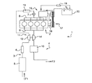
図1に示されている通り、本発明によるモータリゼーションデバイス1は、車両、詳細には自動車に適合されていてもよい。該モータリゼーションデバイスは、例えばディーゼルエンジンなどの熱機関2すなわち内燃エンジン、つまりこの場合は限定ではないが4気筒直列エンジンを具備する。 As shown in FIG. 1, the motorization device 1 according to the invention may be adapted to a vehicle, in particular an automobile. The motorization device comprises a heat engine 2, i.e. an internal combustion engine, for example a diesel engine, i.e. in this case, without limitation, a four-cylinder in-line engine.
作動するために、このような熱機関2は、進入ライン3を介して矢印F1の方向に空気を吸い込み、該空気を矢印F2の方向に外部雰囲気中に放出するために、排気ライン4を介して関連燃焼ガスを放出する。
In order to operate, such a heat engine 2 draws air in the direction of arrow F1 via the
また、エンジンは、例えばシリンダ用の超高圧の共通燃料レールと、燃料を各シリンダ内に直接噴射することができる、1シリンダ当たり少なくとも1つの燃料噴射装置とを具備する直接噴射システムなどの、噴射システム(図示せず)を使用してエンジンに供給される燃料、例えばディーゼル、を使用する。 The engine may also be an injection, such as a direct injection system comprising an ultra-high pressure common fuel rail for cylinders and at least one fuel injector per cylinder capable of directly injecting fuel into each cylinder. A fuel (eg diesel) is used that is supplied to the engine using a system (not shown).
限定ではないが、空気進入ライン3は、空気フィルタ5と、エンジン2内に吸い込まれる外気の質量流量を判定する流量計6と、エンジン2内への流量を制御するのに使用される吸気弁7と、吸気弁7を通過する空気をエンジン2の様々なシリンダへ案内する吸気マニホルド8または分配器8とを具備し得る。
The
限定ではないが、排気ライン4は、排気マニホルド9と、エンジンからの燃焼ガス用の少なくとも1つの処理後デバイス10、例えば酸化触媒コンバータ10、粒子フィルタ10、NOx吸収器10、またはNOx選択的還元触媒10、とを具備し得る。
Without limitation, the exhaust line 4 includes an
この場合にはエンジン2が過給されるので、熱機関2はまた、圧縮機12が流量計6と吸気弁7との間の進入ライン3上に配置されているターボチャージャ11を具備する。さらに、熱交換器13が、圧縮機12と吸気弁7との間の進入ライン3上に配置されていて、圧縮機12により圧縮された空気を冷却してもよい。
Since the engine 2 is supercharged in this case, the heat engine 2 also comprises a
圧縮機12は、エンジン2と処理後デバイス10との間の排気ライン4上に配置されているターボチャージャ11のタービン14により駆動される。従来、排気ライン4は、タービン14を迂回しかつ排気孔(「廃棄ゲート」とも呼ばれる)への放出弁を有し、タービン14への排ガスにより供給されるエネルギーを制限し、したがって圧縮機12により与えられる圧力を制限するバイパスライン(図示せず)を設けられている可能性がある。あるいは、ターボチャージャ11は、可変形状タービン、すなわち排ガスから取られるエネルギーが調節されることを可能にする可変傾斜翼を設けられているものを有し得る。
The
さらに、熱機関2は、本発明の範囲をこれにより制限することなく、吸入口(図示せず)まで排ガスを再循環させる1つまたは複数の回路、より具体的には低圧排ガス再循環(EGR)回路および/または高圧排ガス再循環(EGR)回路を具備し得る。 In addition, the heat engine 2 can be used to recirculate exhaust gas to an inlet (not shown), more specifically, low pressure exhaust gas recirculation (EGR) without limiting the scope of the present invention thereby. ) Circuit and / or high pressure exhaust gas recirculation (EGR) circuit.
既知の方法では、熱機関2(この場合はディーゼルエンジン2)は希薄混合気で作動し、トルク(熱トルクCtとも呼ばれる)を生成する。この熱トルクCtは、エンジン2のプロセッサにより定められる量での、エンジンが希薄混合気で作動している場合は化学量論比より小さい比での、(吸入口で再生排ガスと組み合わされる可能性がある)外気と燃料との混合物の、エンジン2における燃焼に起因する。 In a known manner, the heat engine 2 (in this case the diesel engine 2) operates with a lean mixture and generates torque (also called thermal torque Ct ). This thermal torque C t is in an amount determined by the processor of the engine 2 and in a ratio less than the stoichiometric ratio when the engine is operating with a lean mixture (can be combined with the regenerated exhaust gas at the inlet. This is due to combustion in the engine 2 of a mixture of outside air and fuel.
本発明による始動方法を実施するために、モータリゼーションデバイス1はまた、図1に示されている通り、可逆電気機械15を具備する。
In order to carry out the starting method according to the invention, the motorization device 1 also comprises a reversible
電気機械15、例えば回転シャフト16が伝達手段17を介して熱機関2の回転トルク出力シャフト18、例えばクランクシャフト、に連結されている、熱機関2のフライホイールから分離されているスタータオルタネータ15は、制御ユニット19の管理下で動力モードまたは発電機モードで作動することができる。
An
発電機モードでは、電気機械15は、バッテリパック20内に蓄積されるようになされている電流を供給するオルタネータであり、抵抗電気トルクCeを引き出す。動力モードでは、逆に、電気機械15は、以前にバッテリ20内に蓄積された電流により電力を供給され、熱機関の回転トルク出力シャフト18に伝達される前に、すなわち車両パワートレインが係合された場合、車両のホイールに、熱機関のトルクCtと組み合わさる電気駆動トルクCeをもたらす。
In generator mode, the
モータリゼーションデバイス1の作動モードは以下の通りである:運転者による車両のアクセルペダル(図示せず)の押下が、プロセッサ(図示せず)によりトルク値に非常に広く変換され、車両のホイールに伝達される。 The mode of operation of the motorization device 1 is as follows: the depression of the accelerator pedal (not shown) of the vehicle by the driver is very widely converted into a torque value by a processor (not shown) and transmitted to the wheel of the vehicle Is done.
車両を冷間始動すると、アクセルペダルは押し下げられず、エンジンは解除される。トルク値は、エンジン2の出力回転シャフト18上で利用可能な始動トルク値Cに等しい。この始動トルクCは、例えば、熱機関2を始動すると燃料噴射を制御する最適化された方法を開示している文献フランス特許出願公開第2980529(A1)号明細書に見られる教示を用いて定められ得ることが有利であり、本方法は、エンジン2の参考加速度と瞬間加速度の間の差に応じて始動時の参考燃料量を決定するステップを含む。
When the vehicle is cold started, the accelerator pedal is not depressed and the engine is released. The torque value is equal to the starting torque value C available on the
上記は、本発明による、電気機械15を具備するモータリゼーションデバイス1の場合、熱機関2を始動させる必要がある始動トルクCが、詳細には熱機関のアイドル速度の達成に続いて、熱トルクCt、電気トルクCe、または両方の組合せのいずれかの形で得られることを実証している。いずれの場合でも、トルク値Cは、次の式:C=Ct+Ceを用いる、熱トルクCtと電気トルクCeとの代数和に等しく、電気トルクは、電気機械15の動力モードでは正の値、発電機モードでは負の値を有する。
In the case of the motorization device 1 comprising an
車両プロセッサ(図示せず)が、車両および/またはモータリゼーションデバイス1の様々なパラメータの関数としての分布を算出する。より具体的には、熱機関2を冷間始動すると、始動トルクCは、通常、エンジン速度に関わらず非常に低く、例えばエンジン2の最大負荷の4分の1未満である。 A vehicle processor (not shown) calculates the distribution as a function of various parameters of the vehicle and / or motorization device 1. More specifically, when the heat engine 2 is cold started, the starting torque C is usually very low regardless of the engine speed, for example, less than a quarter of the maximum load of the engine 2.
次いで、負荷点(load point)で、すなわち始動トルクCより高い熱トルクCt、好ましくは熱機関における燃焼が最も安定的なトルクで、熱機関2を作動させることが特に有利である。 Then, the load point (load point), i.e. high heat torque C t from the starting torque C, and preferably most stable torque combustion in a heat engine, operating the heat engine 2 is particularly advantageous.
換言すれば、始動するのに必須であろう熱トルクCtは、正の熱トルク差ΔCにより増大され、結果として得られる熱トルクC+ΔCは不安定燃焼を最小限にし、これにより、車両内で感じられる振動および熱機関2によるアルデヒドの排出が低減される。 In other words, the thermal torque C t that would be essential for starting is increased by the positive thermal torque difference ΔC, and the resulting thermal torque C + ΔC minimizes unstable combustion, thereby causing in-vehicle Felt vibrations and aldehyde emissions by the heat engine 2 are reduced.
このような値は、エンジン試験台上で試験することにより、例えば各燃焼サイクルにより個別に生成される圧力を測定することができるシリンダ圧力センサを熱機関2に適合させることにより、予め実験的に決定され得る。実際、不安定燃焼が、異なるサイクル間のシリンダ圧力信号の顕著な統計的分散をもたらす。 Such values can be tested experimentally in advance by testing on an engine test bench, for example by adapting the heat pressure to a cylinder pressure sensor that can measure the pressure generated individually by each combustion cycle. Can be determined. In fact, unstable combustion results in significant statistical dispersion of the cylinder pressure signal between different cycles.
熱機関2における燃焼が最も安定しているトルクは、エンジン速度に応じて変化し得る。その結果として、エンジン2を始動すると、エンジンの回転速度がゼロからアイドル速度になり、結果として得られる熱トルクC+ΔCは、例えばエンジン2のクランクシャフトに取り付けられている速度センサにより測定されるに従って、エンジンの各回転速度値に関して調節され得る。簡易化された変形形態では、結果として得られる熱トルクC+ΔCは、アイドル速度でのみ不安定燃焼を最小限にする値に調整される。 The torque at which combustion in the heat engine 2 is most stable can vary depending on the engine speed. As a result, when the engine 2 is started, the rotational speed of the engine goes from zero to idle speed, and the resulting thermal torque C + ΔC is measured by a speed sensor attached to the crankshaft of the engine 2, for example, It can be adjusted for each engine speed value. In a simplified variant, the resulting thermal torque C + ΔC is adjusted to a value that minimizes unstable combustion only at idle speed.
増大する熱トルクが、発電機モードで作動している電気機械15により相殺され、式Ce=−ΔCに基づいて、正のトルク差ΔCを引き出す。
The increasing thermal torque is canceled out by the
しかし、電気機械の制御ユニット19は、バッテリ20の充電CBをモニタするための手段を具備する。充電レベルCBが最大充電レベルCBmaxに到達した場合、制御ユニット19は、電気機械15が発電機モードで使用されないようにする。
However, the
発電機モードでの電気機械15の作動中に回復されたエネルギーは、その後、車両の他の使用段階で戻されることが可能であり、動力モードで作動している電気機械15で車両を駆動するのに使用され得ることが有利である。
The energy recovered during operation of the
図2は、前段で開示されているものなどのモータリゼーションデバイス1を使用して、本発明による、熱機関2を始動する本方法の実施形態の様々なステップを示す。 FIG. 2 shows various steps of an embodiment of the method for starting a heat engine 2 according to the present invention using a motorization device 1 such as that disclosed in the preceding paragraph.
本方法は、熱機関2のための始動ステップ100を含む。本方法は、次いで、繰り返し実施されるいくつかのステップを含む。
The method includes a starting
また、本方法は、エンジン2の冷間作動モードを示すパラメータが測定される第1の決定ステップ200を含む。図2に示されている実施形態では、該パラメータは、エンジンの作動を示す温度値θ、例えば(既知のセンサを使用して測定される)水または油の温度、である。図示されていない別の実施形態では、エンジン2が始動されたので、該パラメータは時間τであってもよく、これは車両内のプロセッサに格納される。
The method also includes a
本方法は、次いで、エンジンの作動を示すパラメータθが最大閾値θsと比較される試験ステップ300を含む。エンジンが始動したのでパラメータが時間τである図示されていない実施形態では、この時間τは最大時間閾値τsと比較される。パラメータθ、τが閾値θs、τsと少なくとも等しい場合は処置が取られない。換言すれば、本方法は、新しい始動ステップ100を続行し得るのみである。
The method then includes a
その逆である場合、本方法は、バッテリ20の充電CBを判定するステップ400に進む。その後、試験ステップ500では、充電レベルCBがチェックされて、バッテリの最大充電レベルCBmaxより低いかどうかを判定する。低くない場合、本方法は終了し、新しい始動ステップ100を続行し得るのみである。さもなければ、本方法は、
− 熱機関2の熱トルクCtが、最大で熱機関のトルク不安定性を最小限にする値まで、正の熱トルク差ΔCにより増大され、
− 正のトルク差ΔCが、電動機モードで作動している電気機械により引き出される
間に、始動トルクCを分配するステップ600に進む。
If vice versa, the method proceeds to step 400 to determine the charge CB of the
The thermal torque C t of the heat engine 2 is increased by a positive thermal torque difference ΔC, up to a value that minimizes the torque instability of the heat engine,
-Proceed to step 600 to distribute the starting torque C while the positive torque difference ΔC is drawn by the electric machine operating in motor mode.
ステップ600の完了時、本方法は、所定の遅延、例えば数十ミリ秒、後に、ステップ200に戻る。
Upon completion of
図3は、本発明による方法を実施した場合、実施しなかった場合それぞれの、冷間始動中の熱機関の速度変動を示す。視認性のために、本方法を用いることにより得られるエンジン速度の変化を示す曲線は上方に移行されており、既知の始動方法を用いて得られる曲線から、該曲線をより良く区別している。 FIG. 3 shows the speed variation of the heat engine during the cold start when the method according to the invention is implemented and when not implemented. For visibility, the curve showing the change in engine speed obtained by using the present method has been shifted upwards to better distinguish it from the curve obtained using known starting methods.
詳細にはアイドル速度が到達される段階の間に、本方法の実施がエンジン速度の安定性を向上させ、これにより他方の曲線に対してより少ない個々の速度ピークがもたらされることが認められる。この回転速度の安定性は、より高い負荷点(トルク)で、換言すれば継続的な個々の燃焼サイクル間のシリンダ圧力のより小さい変動性で作動している熱機関におけるより大きな燃焼安定性に因る。 In particular, during the stage where idle speed is reached, it can be seen that implementation of the method improves engine speed stability, which results in fewer individual speed peaks for the other curve. This rotational speed stability is at a higher load point (torque), in other words, greater combustion stability in a heat engine operating with less variability in cylinder pressure between successive individual combustion cycles. It depends.
Claims (8)
前記熱機関(2)の冷間作動を表すパラメータ(θ、τ)の値を決定するステップと、
前記パラメータ(θ、τ)の値を閾値(θs、τs)と比較するステップと、
前記パラメータ(θ、τ)の値が前記閾値(θs、τs)より低い限り、
a.前記熱機関(2)の熱トルクC t を、
C t =C+ΔC (式)
ここに、Cは前記熱機関(2)の始動トルクを、ΔCは正のトルク差を表す、
に従って決定して、
前記熱機関の燃焼がより安定的になる、前記熱機関(2)の始動トルクCより高い値に前記熱機関(2)の熱トルクC t を増大させるとともに、
b.前記可逆電気機械(15)を前記発電機モードで作動させて、前記熱トルクに加えられる正のトルク差ΔCを吸収するステップと
を含む、方法。 The heat engine (2) is combined with a reversible electric machine (15) that can operate in generator mode or power mode, sharing the available torque on the rotating torque output shaft (18) that drives the vehicle. In a hybrid vehicle, a method of cold starting the heat engine (2) capable of driving at least one drive wheel of the hybrid vehicle,
Determining values of parameters (θ, τ) representing cold operation of the heat engine (2);
Comparing the values of the parameters (θ, τ) with threshold values (θ s , τ s );
As long as the value of the parameter (θ, τ) is lower than the threshold value (θ s , τ s ),
a. The thermal torque C t of the heat engine (2) is
C t = C + ΔC (formula)
Here, C represents the starting torque of the heat engine (2), and ΔC represents a positive torque difference.
Determined according to
Combustion becomes more stable of the heat engine, along with increasing the thermal torque C t of the heat engine (2) to a value higher than the starting torque C of the heat engine (2),
b. The reversible electric machine (15) is operated in the generator mode, the step and the including of absorbing positive torque difference ΔC applied to the heat torque method.
Applications Claiming Priority (3)
| Application Number | Priority Date | Filing Date | Title |
|---|---|---|---|
| FR1363155A FR3015374B1 (en) | 2013-12-20 | 2013-12-20 | METHOD FOR COLD STARTING A HEAT ENGINE AND ASSOCIATED MOTORIZATION DEVICE |
| FR1363155 | 2013-12-20 | ||
| PCT/FR2014/052917 WO2015092179A1 (en) | 2013-12-20 | 2014-11-14 | Method for cold-starting a heat engine and associated drive device |
Publications (2)
| Publication Number | Publication Date |
|---|---|
| JP2017503107A JP2017503107A (en) | 2017-01-26 |
| JP6437558B2 true JP6437558B2 (en) | 2018-12-12 |
Family
ID=50424506
Family Applications (1)
| Application Number | Title | Priority Date | Filing Date |
|---|---|---|---|
| JP2016539997A Active JP6437558B2 (en) | 2013-12-20 | 2014-11-14 | Method and starter for cold starting a heat engine |
Country Status (5)
| Country | Link |
|---|---|
| EP (1) | EP3083358B1 (en) |
| JP (1) | JP6437558B2 (en) |
| KR (1) | KR102072840B1 (en) |
| FR (1) | FR3015374B1 (en) |
| WO (1) | WO2015092179A1 (en) |
Families Citing this family (3)
| Publication number | Priority date | Publication date | Assignee | Title |
|---|---|---|---|---|
| JP6423026B2 (en) * | 2017-02-09 | 2018-11-14 | 本田技研工業株式会社 | Hybrid car |
| CN111661032B (en) * | 2020-06-22 | 2021-05-07 | 浙江吉利新能源商用车集团有限公司 | Control method and system of hybrid power vehicle |
| CN113246960B (en) * | 2021-05-19 | 2023-03-21 | 上汽通用五菱汽车股份有限公司 | Engine cold start method, automobile and computer readable storage medium |
Family Cites Families (10)
| Publication number | Priority date | Publication date | Assignee | Title |
|---|---|---|---|---|
| JP3047621B2 (en) * | 1992-05-25 | 2000-05-29 | トヨタ自動車株式会社 | Control device for engine-driven generator of hybrid vehicle |
| JP2001132491A (en) * | 1999-08-26 | 2001-05-15 | Honda Motor Co Ltd | Catalyst warm-up control device for hybrid automobile |
| US6664651B1 (en) * | 2000-11-14 | 2003-12-16 | Ford Motor Company | Engine on idle arbitration for a hybrid electric vehicle |
| JP3958220B2 (en) | 2003-01-16 | 2007-08-15 | 株式会社豊田中央研究所 | Torque transmission device |
| JP3700715B2 (en) * | 2003-08-12 | 2005-09-28 | トヨタ自動車株式会社 | Control device for internal combustion engine |
| DE102007050117B4 (en) * | 2007-10-19 | 2021-07-29 | Robert Bosch Gmbh | Method for operating a hybrid drive device and hybrid drive device |
| DE102007050114A1 (en) * | 2007-10-19 | 2009-04-23 | Robert Bosch Gmbh | A method of operating a hybrid propulsion device of a vehicle, hybrid propulsion device |
| US8020652B2 (en) * | 2007-12-04 | 2011-09-20 | Ford Global Technologies, Llc | Generator power-based cold start strategy |
| JP5201236B2 (en) * | 2011-03-31 | 2013-06-05 | トヨタ自動車株式会社 | Control device for internal combustion engine |
| FR2980529B1 (en) | 2011-09-26 | 2015-01-09 | Renault Sa | FUEL INJECTION CONTROL WHEN STARTING A THERMAL ENGINE |
-
2013
- 2013-12-20 FR FR1363155A patent/FR3015374B1/en not_active Expired - Fee Related
-
2014
- 2014-11-14 JP JP2016539997A patent/JP6437558B2/en active Active
- 2014-11-14 WO PCT/FR2014/052917 patent/WO2015092179A1/en active Application Filing
- 2014-11-14 KR KR1020167017307A patent/KR102072840B1/en active IP Right Grant
- 2014-11-14 EP EP14821706.0A patent/EP3083358B1/en active Active
Also Published As
| Publication number | Publication date |
|---|---|
| KR102072840B1 (en) | 2020-02-03 |
| FR3015374B1 (en) | 2016-01-22 |
| EP3083358B1 (en) | 2018-02-28 |
| FR3015374A1 (en) | 2015-06-26 |
| JP2017503107A (en) | 2017-01-26 |
| EP3083358A1 (en) | 2016-10-26 |
| WO2015092179A1 (en) | 2015-06-25 |
| KR20160100313A (en) | 2016-08-23 |
Similar Documents
| Publication | Publication Date | Title |
|---|---|---|
| JP3959084B2 (en) | Manifold absolute pressure control system and method for hybrid electric vehicle | |
| RU2719087C2 (en) | Method of controlling power plant of motor vehicle during acceleration event and motor vehicle | |
| JP5632882B2 (en) | Catalyst warm-up control device for hybrid vehicle | |
| RU2719409C2 (en) | METHOD TO REDUCE ENGINE NOx EMISSIONS | |
| US10690065B2 (en) | Control device of vehicle | |
| JP2012502221A (en) | On-vehicle diagnosis method and on-vehicle diagnosis system | |
| JP2014098348A (en) | Vehicle control device | |
| JP2005273530A (en) | Control device for internal combustion engine and automobile equipped therewith | |
| KR20160097253A (en) | Exhaust line for an internal combustion engine and internal combustion engine comprising such an exhaust line | |
| KR20180068186A (en) | Method and system for controlling mhsg of mild hybrid electric vehicle | |
| JP6437558B2 (en) | Method and starter for cold starting a heat engine | |
| JP4626383B2 (en) | Control device for internal combustion engine having supercharger with electric motor | |
| JP2006177171A (en) | Control device for supercharger with electric motor and automobile provided with the control device | |
| US10077043B2 (en) | Method and apparatus for controlling mild hybrid electric vehicle | |
| JP2008075565A (en) | Control device for internal combustion engine | |
| JP6168097B2 (en) | Hybrid car | |
| WO2009090456A2 (en) | Control apparatus and control method for hybrid system | |
| WO2008047816A1 (en) | Control device for internal combustion engine | |
| JP5829838B2 (en) | Engine brake control device | |
| KR20180068168A (en) | Method and appratus for heating lambda sensor of mild hybrid electric vehicle | |
| US20230227022A1 (en) | Hybrid electric vehicle | |
| JP7176492B2 (en) | vehicle | |
| JP7200922B2 (en) | vehicle | |
| JP6070980B2 (en) | Control device for internal combustion engine | |
| JP4858237B2 (en) | Control device for internal combustion engine |
Legal Events
| Date | Code | Title | Description |
|---|---|---|---|
| A621 | Written request for application examination |
Free format text: JAPANESE INTERMEDIATE CODE: A621 Effective date: 20171113 |
|
| A977 | Report on retrieval |
Free format text: JAPANESE INTERMEDIATE CODE: A971007 Effective date: 20180606 |
|
| A131 | Notification of reasons for refusal |
Free format text: JAPANESE INTERMEDIATE CODE: A131 Effective date: 20180612 |
|
| A521 | Request for written amendment filed |
Free format text: JAPANESE INTERMEDIATE CODE: A523 Effective date: 20180911 |
|
| TRDD | Decision of grant or rejection written | ||
| A01 | Written decision to grant a patent or to grant a registration (utility model) |
Free format text: JAPANESE INTERMEDIATE CODE: A01 Effective date: 20181016 |
|
| A61 | First payment of annual fees (during grant procedure) |
Free format text: JAPANESE INTERMEDIATE CODE: A61 Effective date: 20181114 |
|
| R150 | Certificate of patent or registration of utility model |
Ref document number: 6437558 Country of ref document: JP Free format text: JAPANESE INTERMEDIATE CODE: R150 |
|
| R250 | Receipt of annual fees |
Free format text: JAPANESE INTERMEDIATE CODE: R250 |
|
| R250 | Receipt of annual fees |
Free format text: JAPANESE INTERMEDIATE CODE: R250 |
|
| R250 | Receipt of annual fees |
Free format text: JAPANESE INTERMEDIATE CODE: R250 |
|
| S111 | Request for change of ownership or part of ownership |
Free format text: JAPANESE INTERMEDIATE CODE: R313113 |
|
| S531 | Written request for registration of change of domicile |
Free format text: JAPANESE INTERMEDIATE CODE: R313531 |
|
| R360 | Written notification for declining of transfer of rights |
Free format text: JAPANESE INTERMEDIATE CODE: R360 |
|
| R360 | Written notification for declining of transfer of rights |
Free format text: JAPANESE INTERMEDIATE CODE: R360 |
|
| R371 | Transfer withdrawn |
Free format text: JAPANESE INTERMEDIATE CODE: R371 |
|
| S531 | Written request for registration of change of domicile |
Free format text: JAPANESE INTERMEDIATE CODE: R313531 |
|
| R350 | Written notification of registration of transfer |
Free format text: JAPANESE INTERMEDIATE CODE: R350 |
|
| S111 | Request for change of ownership or part of ownership |
Free format text: JAPANESE INTERMEDIATE CODE: R313113 |