JP6436165B2 - Image forming method - Google Patents
Image forming method Download PDFInfo
- Publication number
- JP6436165B2 JP6436165B2 JP2016511897A JP2016511897A JP6436165B2 JP 6436165 B2 JP6436165 B2 JP 6436165B2 JP 2016511897 A JP2016511897 A JP 2016511897A JP 2016511897 A JP2016511897 A JP 2016511897A JP 6436165 B2 JP6436165 B2 JP 6436165B2
- Authority
- JP
- Japan
- Prior art keywords
- ink
- recording medium
- image forming
- actinic ray
- forming method
- Prior art date
- Legal status (The legal status is an assumption and is not a legal conclusion. Google has not performed a legal analysis and makes no representation as to the accuracy of the status listed.)
- Active
Links
Images


Classifications
-
- B—PERFORMING OPERATIONS; TRANSPORTING
- B41—PRINTING; LINING MACHINES; TYPEWRITERS; STAMPS
- B41J—TYPEWRITERS; SELECTIVE PRINTING MECHANISMS, i.e. MECHANISMS PRINTING OTHERWISE THAN FROM A FORME; CORRECTION OF TYPOGRAPHICAL ERRORS
- B41J2/00—Typewriters or selective printing mechanisms characterised by the printing or marking process for which they are designed
- B41J2/005—Typewriters or selective printing mechanisms characterised by the printing or marking process for which they are designed characterised by bringing liquid or particles selectively into contact with a printing material
- B41J2/01—Ink jet
- B41J2/21—Ink jet for multi-colour printing
- B41J2/2132—Print quality control characterised by dot disposition, e.g. for reducing white stripes or banding
- B41J2/2146—Print quality control characterised by dot disposition, e.g. for reducing white stripes or banding for line print heads
-
- B—PERFORMING OPERATIONS; TRANSPORTING
- B41—PRINTING; LINING MACHINES; TYPEWRITERS; STAMPS
- B41J—TYPEWRITERS; SELECTIVE PRINTING MECHANISMS, i.e. MECHANISMS PRINTING OTHERWISE THAN FROM A FORME; CORRECTION OF TYPOGRAPHICAL ERRORS
- B41J11/00—Devices or arrangements of selective printing mechanisms, e.g. ink-jet printers or thermal printers, for supporting or handling copy material in sheet or web form
- B41J11/0015—Devices or arrangements of selective printing mechanisms, e.g. ink-jet printers or thermal printers, for supporting or handling copy material in sheet or web form for treating before, during or after printing or for uniform coating or laminating the copy material before or after printing
- B41J11/002—Curing or drying the ink on the copy materials, e.g. by heating or irradiating
- B41J11/0021—Curing or drying the ink on the copy materials, e.g. by heating or irradiating using irradiation
- B41J11/00214—Curing or drying the ink on the copy materials, e.g. by heating or irradiating using irradiation using UV radiation
-
- B—PERFORMING OPERATIONS; TRANSPORTING
- B41—PRINTING; LINING MACHINES; TYPEWRITERS; STAMPS
- B41J—TYPEWRITERS; SELECTIVE PRINTING MECHANISMS, i.e. MECHANISMS PRINTING OTHERWISE THAN FROM A FORME; CORRECTION OF TYPOGRAPHICAL ERRORS
- B41J2/00—Typewriters or selective printing mechanisms characterised by the printing or marking process for which they are designed
- B41J2/005—Typewriters or selective printing mechanisms characterised by the printing or marking process for which they are designed characterised by bringing liquid or particles selectively into contact with a printing material
- B41J2/01—Ink jet
- B41J2/135—Nozzles
- B41J2/14—Structure thereof only for on-demand ink jet heads
-
- B—PERFORMING OPERATIONS; TRANSPORTING
- B41—PRINTING; LINING MACHINES; TYPEWRITERS; STAMPS
- B41J—TYPEWRITERS; SELECTIVE PRINTING MECHANISMS, i.e. MECHANISMS PRINTING OTHERWISE THAN FROM A FORME; CORRECTION OF TYPOGRAPHICAL ERRORS
- B41J2/00—Typewriters or selective printing mechanisms characterised by the printing or marking process for which they are designed
- B41J2/005—Typewriters or selective printing mechanisms characterised by the printing or marking process for which they are designed characterised by bringing liquid or particles selectively into contact with a printing material
- B41J2/01—Ink jet
- B41J2/135—Nozzles
- B41J2/145—Arrangement thereof
- B41J2/155—Arrangement thereof for line printing
-
- C—CHEMISTRY; METALLURGY
- C09—DYES; PAINTS; POLISHES; NATURAL RESINS; ADHESIVES; COMPOSITIONS NOT OTHERWISE PROVIDED FOR; APPLICATIONS OF MATERIALS NOT OTHERWISE PROVIDED FOR
- C09D—COATING COMPOSITIONS, e.g. PAINTS, VARNISHES OR LACQUERS; FILLING PASTES; CHEMICAL PAINT OR INK REMOVERS; INKS; CORRECTING FLUIDS; WOODSTAINS; PASTES OR SOLIDS FOR COLOURING OR PRINTING; USE OF MATERIALS THEREFOR
- C09D11/00—Inks
- C09D11/02—Printing inks
- C09D11/10—Printing inks based on artificial resins
- C09D11/101—Inks specially adapted for printing processes involving curing by wave energy or particle radiation, e.g. with UV-curing following the printing
-
- C—CHEMISTRY; METALLURGY
- C09—DYES; PAINTS; POLISHES; NATURAL RESINS; ADHESIVES; COMPOSITIONS NOT OTHERWISE PROVIDED FOR; APPLICATIONS OF MATERIALS NOT OTHERWISE PROVIDED FOR
- C09D—COATING COMPOSITIONS, e.g. PAINTS, VARNISHES OR LACQUERS; FILLING PASTES; CHEMICAL PAINT OR INK REMOVERS; INKS; CORRECTING FLUIDS; WOODSTAINS; PASTES OR SOLIDS FOR COLOURING OR PRINTING; USE OF MATERIALS THEREFOR
- C09D11/00—Inks
- C09D11/02—Printing inks
- C09D11/10—Printing inks based on artificial resins
- C09D11/106—Printing inks based on artificial resins containing macromolecular compounds obtained by reactions only involving carbon-to-carbon unsaturated bonds
- C09D11/107—Printing inks based on artificial resins containing macromolecular compounds obtained by reactions only involving carbon-to-carbon unsaturated bonds from unsaturated acids or derivatives thereof
-
- C—CHEMISTRY; METALLURGY
- C09—DYES; PAINTS; POLISHES; NATURAL RESINS; ADHESIVES; COMPOSITIONS NOT OTHERWISE PROVIDED FOR; APPLICATIONS OF MATERIALS NOT OTHERWISE PROVIDED FOR
- C09D—COATING COMPOSITIONS, e.g. PAINTS, VARNISHES OR LACQUERS; FILLING PASTES; CHEMICAL PAINT OR INK REMOVERS; INKS; CORRECTING FLUIDS; WOODSTAINS; PASTES OR SOLIDS FOR COLOURING OR PRINTING; USE OF MATERIALS THEREFOR
- C09D11/00—Inks
- C09D11/02—Printing inks
- C09D11/12—Printing inks based on waxes or bitumen
-
- C—CHEMISTRY; METALLURGY
- C09—DYES; PAINTS; POLISHES; NATURAL RESINS; ADHESIVES; COMPOSITIONS NOT OTHERWISE PROVIDED FOR; APPLICATIONS OF MATERIALS NOT OTHERWISE PROVIDED FOR
- C09D—COATING COMPOSITIONS, e.g. PAINTS, VARNISHES OR LACQUERS; FILLING PASTES; CHEMICAL PAINT OR INK REMOVERS; INKS; CORRECTING FLUIDS; WOODSTAINS; PASTES OR SOLIDS FOR COLOURING OR PRINTING; USE OF MATERIALS THEREFOR
- C09D11/00—Inks
- C09D11/30—Inkjet printing inks
- C09D11/32—Inkjet printing inks characterised by colouring agents
- C09D11/322—Pigment inks
-
- C—CHEMISTRY; METALLURGY
- C09—DYES; PAINTS; POLISHES; NATURAL RESINS; ADHESIVES; COMPOSITIONS NOT OTHERWISE PROVIDED FOR; APPLICATIONS OF MATERIALS NOT OTHERWISE PROVIDED FOR
- C09D—COATING COMPOSITIONS, e.g. PAINTS, VARNISHES OR LACQUERS; FILLING PASTES; CHEMICAL PAINT OR INK REMOVERS; INKS; CORRECTING FLUIDS; WOODSTAINS; PASTES OR SOLIDS FOR COLOURING OR PRINTING; USE OF MATERIALS THEREFOR
- C09D11/00—Inks
- C09D11/30—Inkjet printing inks
- C09D11/34—Hot-melt inks
-
- C—CHEMISTRY; METALLURGY
- C09—DYES; PAINTS; POLISHES; NATURAL RESINS; ADHESIVES; COMPOSITIONS NOT OTHERWISE PROVIDED FOR; APPLICATIONS OF MATERIALS NOT OTHERWISE PROVIDED FOR
- C09D—COATING COMPOSITIONS, e.g. PAINTS, VARNISHES OR LACQUERS; FILLING PASTES; CHEMICAL PAINT OR INK REMOVERS; INKS; CORRECTING FLUIDS; WOODSTAINS; PASTES OR SOLIDS FOR COLOURING OR PRINTING; USE OF MATERIALS THEREFOR
- C09D11/00—Inks
- C09D11/30—Inkjet printing inks
- C09D11/40—Ink-sets specially adapted for multi-colour inkjet printing
-
- B—PERFORMING OPERATIONS; TRANSPORTING
- B41—PRINTING; LINING MACHINES; TYPEWRITERS; STAMPS
- B41M—PRINTING, DUPLICATING, MARKING, OR COPYING PROCESSES; COLOUR PRINTING
- B41M5/00—Duplicating or marking methods; Sheet materials for use therein
- B41M5/0023—Digital printing methods characterised by the inks used
-
- B—PERFORMING OPERATIONS; TRANSPORTING
- B41—PRINTING; LINING MACHINES; TYPEWRITERS; STAMPS
- B41M—PRINTING, DUPLICATING, MARKING, OR COPYING PROCESSES; COLOUR PRINTING
- B41M7/00—After-treatment of prints, e.g. heating, irradiating, setting of the ink, protection of the printed stock
- B41M7/0081—After-treatment of prints, e.g. heating, irradiating, setting of the ink, protection of the printed stock using electromagnetic radiation or waves, e.g. ultraviolet radiation, electron beams
Description
本発明は、画像形成方法に関する。 The present invention relates to an image forming method.
インクジェット記録方式は、簡易かつ安価に画像を形成できることから、各種印刷分野で用いられている。インクジェット記録方式の一つとして、紫外線硬化型インクジェットインクの液滴を記録媒体に着弾させた後、紫外線を照射して硬化させて画像を形成する紫外線硬化型インクジェット方式がある。紫外線硬化型インクジェット方式は、インク吸収性のない記録媒体においても、高い耐擦過性と密着性を有する画像を形成できることから、近年注目されつつある。 The ink jet recording system is used in various printing fields because it can form an image easily and inexpensively. As one of the ink jet recording methods, there is an ultraviolet curable ink jet method in which droplets of ultraviolet curable ink jet ink are landed on a recording medium and then cured by irradiation with ultraviolet rays to form an image. The ultraviolet curable ink jet method has been attracting attention in recent years because it can form an image having high scratch resistance and adhesion even on a recording medium having no ink absorbability.
例えば、特許文献1では、硬化性インキであって、前記硬化性インキを基材の上に印刷および硬化させたときに、前記基材の印刷領域の光沢が、前記基材の非印刷領域の光沢に密接にマッチする特性を有する、硬化性インキが開示されている。 For example, in Patent Document 1, when the curable ink is printed and cured on a substrate, the gloss of the printed region of the substrate is the non-printed region of the substrate. Curable inks have been disclosed that have properties that closely match gloss.
また、例えば、特許文献2では、ライン状に複数のインク吐出ノズルを配列した複数のインクジェットヘッドを、前記インク吐出ノズルの配列方向に沿って千鳥状に配置した記録装置を用いて、前記インク吐出ノズルより吐出したインク組成物からなる液滴を、前記配列方向に直交する方向に沿って搬送される被記録媒体上に着弾させて印刷するインクジェット記録方法であって、前記直交する方向に隣接する複数の前記インクジェットヘッド間において、端部から少なくとも1つの前記インク吐出ノズルより吐出する前記液滴を、前記被記録媒体上で互いに重なり合うように着弾させる工程を有し、1つの前記インクジェットヘッドにおいて、前記端部から少なくとも1つの前記インク吐出ノズルより吐出する前記液滴の容量は、それ以外の前記インク吐出ノズルより吐出する前気液滴の容量よりも少ないものであり、前記インク組成物の降伏値が、0.50〜2.00mPaである、インクジェット記録方法が開示されている。 Further, for example, in Patent Document 2, the ink ejection is performed using a recording apparatus in which a plurality of inkjet heads in which a plurality of ink ejection nozzles are arranged in a line are arranged in a staggered manner along the arrangement direction of the ink ejection nozzles. An ink jet recording method in which droplets made of an ink composition ejected from a nozzle are landed and printed on a recording medium transported along a direction orthogonal to the arrangement direction, and adjacent to the orthogonal direction In the one inkjet head, the method includes a step of landing the droplets discharged from at least one ink ejection nozzle from an end portion between the plurality of inkjet heads so as to overlap each other on the recording medium. The volume of the liquid droplets discharged from at least one of the ink discharge nozzles from the end is other than that Wherein are those less than the capacity of the front air-liquid droplets ejected from the ink discharge nozzles, yield value of the ink composition is 0.50~2.00MPa, an ink jet recording method is disclosed.
特許文献1に記載の発明の課題は印刷領域の光沢が基材の非印刷領域の光沢と密接にマッチすることであるが、光沢を密接にマッチさせて一致させる具体的な施策については記載がない。また、インク着弾時の記録材料の温度は50℃以下であって、50℃以下において、インクの粘度は、105-107cpの粘度を有しており、紙基材への浸透をも抑えるレベルの粘度を有しており高粘度である。相転移温度−20〜−10℃に記録材料の温度を設定したとしても、隣り合うドットどうしの適度な合一レベリングは起こらない。The problem of the invention described in Patent Document 1 is that the gloss of the printing area closely matches the gloss of the non-printing area of the base material, but there is a description about a specific measure for matching the gloss closely. Absent. In addition, the temperature of the recording material upon landing of the ink is 50 ° C. or less, and the viscosity of the ink is 10 5 -10 7 cp at 50 ° C. or less, and it penetrates into the paper substrate. It has a viscosity of a level to suppress and is highly viscous. Even if the temperature of the recording material is set to a phase transition temperature of -20 to -10 ° C, an appropriate leveling of adjacent dots does not occur.
また、特許文献2に記載の発明のように、複数のインクジェットヘッドを、ノズルの配列方向に沿って千鳥状に配置した記録装置を用いて、隣接する複数のヘッド間において、隣接するヘッド端部の重複した部分に被記録媒体上で互いに重なり合うように着弾させ、インク出射時の曲がりの影響などでヘッド間で画像中に印字されない領域(筋、白ヌケ)の発生を防ぐことは知られているが、可逆的にゾルゲル相転移する紫外線硬化型インクジェットインクにおいては、隣接するヘッド端部の重複した部分に単純に印字しただけでは、前記適度な合一レベリングが得られず画質劣化につながってしまうというという問題がある。 Further, as in the invention described in Patent Document 2, using a recording apparatus in which a plurality of inkjet heads are arranged in a staggered manner along the nozzle arrangement direction, adjacent head end portions between the plurality of adjacent heads It is known to land on the recording medium so as to overlap each other on the recording medium, and to prevent the occurrence of areas that are not printed in the image (streaks, white spots) between the heads due to the influence of bending when ejecting ink, etc. However, in UV curable inkjet ink that reversibly undergoes sol-gel phase transition, simply printing on the overlapping part of the adjacent head ends does not provide the appropriate union leveling, leading to image quality degradation. There is a problem that it ends up.
本発明は上記の事情に鑑みてなされたものであり、その目的とするところは、色混じりを低減できる高画質形成可能なゾルゲル相転移する活性光線硬化型インクジェットインクを用いて、長尺なラインヘッド等にて高速に画像形成をしても、短尺記録素子列(モジュール)の重なり領域(繋ぎ部)の筋(白ヌケ)の故障がなく、かつ、重なり領域(繋ぎ部)の画像光沢違和感の無い画像を形成できる、画期的な画像形成方法を提供することにある。 The present invention has been made in view of the above circumstances, and an object of the present invention is to use an actinic ray curable inkjet ink capable of forming a high image quality and capable of reducing color mixing to form a long line. Even when high-speed image formation is performed with a head or the like, there is no failure of the stripes (white spots) in the overlapping area (joining part) of the short recording element array (module), and the image gloss in the overlapping area (joining part) is uncomfortable. It is an object of the present invention to provide an epoch-making image forming method capable of forming an image having no image.
上記目的を達成するための具体的な手段は、以下の第(1)項〜第(7)項である。
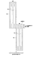
(1)ラインヘッドを用いて活性光線硬化型インクジェットインクを吐出して、記録媒体に着弾させる工程と、該記録媒体を搬送する工程とを含む画像形成方法であって、該ラインヘッドが長尺記録素子列を備え、該長尺記録素子列が複数のモジュールから構成されて、該複数のモジュールのそれぞれのモジュールが、該記録媒体の搬送方向と直行する方向に複数の記録素子が配列されている少なくとも1つの短尺記録素子列を備え、該複数のモジュールが、該短尺記録素子列方向に互いに隣接する該複数のモジュールのうちの少なくとも2つのモジュールの端部同士で、該記録媒体の搬送方向と直行する方向に重なり領域を有した状態で千鳥配置されて、該重なり領域における該少なくとも2つのモジュールの一方のモジュールに備えられている該短尺記録素子列から第一の該インクが吐出されて該記録媒体に着弾された時から、他方のモジュールに備えられている該短尺記録素子列から該第一のインクまたは第一のインクと同一色系である第二のインクが吐出されて該記録媒体に着弾されるまでの時間が25ms以上であり、該活性光線硬化型インクジェットインクが、ゲル化剤を少なくとも含んで、温度により可逆的にゾルゲル相転移をし、該ゲル化剤の含有量が、該インクの全質量に対して0.5〜3.0質量%であり、該活性光線硬化型インクジェットインクを該記録媒体に着弾させる時の温度における、該インクの複素粘度が50〜300Pa・sであることを特徴とする、画像形成方法。
(2)前記重なり領域において形成される画像のドット率が70%以上のときであることを特徴とする、第(1)項に記載の画像形成方法。
(3)前記重なり領域において、前記少なくとも1つの短尺記録素子列の端部から2〜15の前記記録素子分のみから、前記活性光線硬化型インクジェットインクを吐出することを特徴とする、第(1)項又は第(2)項に記載の画像形成方法。
(4)前記ゲル化剤が下記一般式(G1)及び(G2)で表される化合物うちの少なくとも一種の化合物であり、R1〜R4の炭素原子数が20を超えるゲル化剤の含有量が前記活性光線硬化型インクジェットインクの全質量に対して0〜0.9質量%であり、かつ、前記ゲル化剤の含有量が、前記活性光線硬化型インクジェットインクの全質量に対して1.0〜2.4質量%であることを特徴とする、第(1)項〜第(3)項のいずれか1項に記載の画像形成方法。
一般式(G1):R1−CO−R2
一般式(G2):R3−COO−R4
(式中、R1〜R4は、それぞれ独立に、炭素数12以上の直鎖部分を含む炭化水素基を表す。)
(5)前記活性光線硬化型インクジェットインクが前記記録媒体に着弾されて形成された最小ドット径が30〜50μmであることを特徴とする、第(1)項〜第(4)項のいずれか1項に記載の画像形成方法。
(6)前記活性光線硬化型インクジェットインクが光重合性化合物と光重合開始剤とを更に含み、前記記録媒体に着弾された前記活性光線硬化型インクジェットインクに活性光線を照射して前記インクを硬化させる工程を更に含むことを特徴とする、第(1)項〜第(5)項のいずれか1項に記載の画像形成方法。
(7)370〜410nmの波長域にピーク照度を有するLED光源を使用し、さらに前記記録媒体に着弾された前記活性光線硬化型インクジェットインクの表面での最高照度が0.5〜6.0W/cm2であって、かつ、光量が400mJ/cm2未満である条件下で、前記活性光線を照射して前記活性光線硬化型インクジェットインクを硬化させる、第(6)項に記載の画像形成方法。Specific means for achieving the above object are the following items (1) to (7).
(1) An image forming method including a step of ejecting actinic ray curable inkjet ink using a line head and landing on a recording medium, and a step of conveying the recording medium, wherein the line head is long A recording element array, the long recording element array is composed of a plurality of modules, and each module of the plurality of modules has a plurality of recording elements arranged in a direction perpendicular to the conveyance direction of the recording medium. At least one of the plurality of modules adjacent to each other in the direction of the short recording element array, and the transport direction of the recording medium. Are arranged in a staggered manner with an overlapping region in a direction perpendicular to the first and second modules in the overlapping region. The first ink or the first ink from the short recording element array provided in the other module from when the first ink is ejected from the short recording element array and landed on the recording medium. The time from when the second ink having the same color system is discharged to landing on the recording medium is 25 ms or more, and the actinic ray curable inkjet ink contains at least a gelling agent and is reversible depending on the temperature. Sol-gel phase transition is performed, the content of the gelling agent is 0.5 to 3.0% by mass with respect to the total mass of the ink, and the actinic ray curable inkjet ink is landed on the recording medium. An image forming method, wherein the complex viscosity of the ink is 50 to 300 Pa · s at a temperature when the ink is used.
(2) The image forming method according to item (1), wherein the dot rate of the image formed in the overlapping region is 70% or more.
(3) The actinic ray curable inkjet ink is ejected from only 2 to 15 recording elements from the end of the at least one short recording element array in the overlapping region. ) Or the image forming method according to item (2).
(4) The gelling agent is at least one compound of the compounds represented by the following general formulas (G1) and (G2), and the content of the gelling agent in which R1 to R4 have more than 20 carbon atoms is included. It is 0-0.9 mass% with respect to the total mass of the said actinic-light curable inkjet ink, and content of the said gelatinizer is 1.0 with respect to the total mass of the said actinic-light curable inkjet ink. The image forming method according to any one of Items (1) to (3), wherein the image forming method is -2.4 mass%.
General formula (G1): R1-CO-R2
General formula (G2): R3-COO-R4
(In the formula, R1 to R4 each independently represents a hydrocarbon group containing a straight chain portion having 12 or more carbon atoms.)
(5) Any one of (1) to (4), wherein a minimum dot diameter formed by landing the actinic ray curable inkjet ink on the recording medium is 30 to 50 μm. 2. The image forming method according to item 1.
(6) The actinic ray curable inkjet ink further includes a photopolymerizable compound and a photopolymerization initiator, and the actinic ray curable inkjet ink landed on the recording medium is irradiated with actinic rays to cure the ink. The image forming method according to any one of items (1) to (5), further comprising a step of:
(7) An LED light source having a peak illuminance in a wavelength range of 370 to 410 nm is used, and the maximum illuminance on the surface of the actinic ray curable inkjet ink landed on the recording medium is 0.5 to 6.0 W / a cm 2, and and, under conditions quantity is less than 400 mJ / cm 2, by irradiating the active ray to cure the active ray curable ink-jet ink, image forming method according to the (6) section .
本発明によれば、色混じりを低減できる高画質形成可能なゾルゲル相転移する活性光線硬化型インクジェットインクを用いて、長尺なラインヘッド等にて高速に画像形成をしても、短尺記録素子列(モジュール)重なり領域(繋ぎ部)の筋(白ヌケ)の故障がなく、かつ、重なり領域(繋ぎ部)の画像光沢違和感の無い画像を形成できる、画期的な画像形成方法が提供される。 According to the present invention, a short recording element can be used even when high-speed image formation is performed with a long line head or the like using an actinic ray curable inkjet ink capable of forming a high image quality capable of reducing color mixing and capable of phase transition. Provided is an epoch-making image forming method capable of forming an image without a sense of incongruity of image gloss in an overlap region (joint portion) without failure of a line (module) overlap region (joint portion) streak. The
本発明について、以下に詳細に説明をする。 The present invention is described in detail below.
1.画像形成方法
本発明の画像形成方法は、ラインヘッドを用いて活性光線硬化型インクジェットインクを吐出して、記録媒体に着弾させる工程と、記録媒体を搬送する工程とを含む画像形成方法であって、ラインヘッドが長尺記録素子列を備え、長尺記録素子列が複数のモジュールから構成されて、複数のモジュールのそれぞれのモジュールが、記録媒体の搬送方向と直行する方向に複数の記録素子が配列されている少なくとも1つの短尺記録素子列を備え、複数のモジュールが、短尺記録素子列方向に互いに隣接する複数のモジュールのうちの少なくとも2つのモジュールの端部同士で、記録媒体の搬送方向と直行する方向に重なり領域を有した状態で千鳥配置されて、重なり領域における少なくとも2つのモジュールの一方のモジュールに備えられている短尺記録素子列から第一のインクが吐出されて記録媒体に着弾された時から、他方のモジュールに備えられている短尺記録素子列から第一のインクまたは第一のインクと同一色系である第二のインクが吐出されて記録媒体に着弾されるまでの時間が25ms以上であり、活性光線硬化型インクジェットインクが、ゲル化剤を少なくとも含んで、温度により可逆的にゾルゲル相転移をし、ゲル化剤の含有量が、インクの全質量に対して0.5〜3.0質量%であり、活性光線硬化型インクジェットインクを記録媒体に着弾させる時の温度における、インクの複素粘度が50〜300Pa・sであることを特徴とする、画像形成方法である。1. Image Forming Method The image forming method of the present invention is an image forming method including a step of ejecting actinic ray curable inkjet ink using a line head and landing on a recording medium, and a step of conveying the recording medium. The line head includes a long recording element array, and the long recording element array includes a plurality of modules, and each of the modules has a plurality of recording elements in a direction perpendicular to the conveyance direction of the recording medium. A plurality of modules having at least one short recording element array arranged, and at least two of the plurality of modules adjacent to each other in the short recording element array direction; A staggered arrangement with an overlapping area in a direction perpendicular to one of the at least two modules in the overlapping area The same as the first ink or the first ink from the short recording element row provided in the other module from when the first ink is ejected from the short recording element row provided and landed on the recording medium. The time until the second ink, which is a color system, is ejected and landed on the recording medium is 25 ms or more, and the actinic ray curable ink-jet ink contains at least a gelling agent and reversibly changes depending on the temperature. The content of the gelling agent is 0.5 to 3.0% by mass with respect to the total mass of the ink, and the temperature of the ink at the time when the actinic ray curable inkjet ink is landed on the recording medium is The image forming method is characterized in that the complex viscosity is 50 to 300 Pa · s.
本発明による画像形成方法は、色混じりを低減できる高画質形成可能なゾルゲル相転移する活性光線硬化型インクジェットインクを用いて、長尺なラインヘッド等にて高速に画像形成をしても、短尺記録素子列(モジュール)の重なり領域(繋ぎ部)の筋(白ヌケ)の故障がなく、かつ、重なり領域(繋ぎ部)の画像光沢違和感の無い画像を形成できるという効果を奏する。本発明の画像形成方法における第一のインクおよび第二のインクは、例えば、イエロー系インク、マゼンタ系インク、シアン系インク、ブラック系インク等が挙げられる。例えば、ある2つのインクが、色の3要素である、彩度、明度及び色相のうち、少なくとも1つの要素が互いに異なったとしても、互いに同一色系、例えばイエロー系、マゼンタ系、シアン系、ブラック系等であれば、その第一のインクおよび第二のインクは本発明の画像形成方法において、同一色系インクとみなす。 The image forming method according to the present invention uses an actinic ray curable inkjet ink capable of forming a high image quality capable of reducing color mixing, and is capable of forming a short image even if high-speed image formation is performed with a long line head or the like. There is an effect that it is possible to form an image that does not cause a failure of the streaks (white spots) in the overlapping region (joining portion) of the recording element array (module) and that does not have a sense of incongruity in the image gloss of the overlapping region (joining portion). Examples of the first ink and the second ink in the image forming method of the present invention include yellow ink, magenta ink, cyan ink, and black ink. For example, even if at least one of saturation, lightness, and hue of two inks is a three-color element, the same color system, for example, yellow, magenta, cyan, If the ink is black or the like, the first ink and the second ink are regarded as the same color ink in the image forming method of the present invention.
本発明における画像形成方法において、短尺記録素子列の重なり領域(繋ぎ部)は、インク出射時の曲がりの影響などで画像中に印字されない領域(筋、白ヌケ)が発生してしまうため、隣接する短尺記録素子列(ヘッド又はヘッドモジュール)の端部において、重なり領域を設けている。 In the image forming method according to the present invention, the overlapping region (joint portion) of the short recording element arrays is adjacent to the region (streak, white missing) that is not printed in the image due to the influence of the bending at the time of ink ejection. An overlapping region is provided at the end of the short recording element array (head or head module).
本発明者らは、ゾルゲル相転移する活性光線硬化型インクジェットインクを用いたとき、千鳥配置した繋ぎ部である重なり領域において、ある一定時間以上インクが基材へ着弾する時間の差が生じると、繋ぎ部である重なり領域の画像光沢が、その周囲の同色部画像光沢と変化してしまい、差が視認できてしまう問題があることがわかった。ゾルゲル相転移する活性光線硬化型インク特有の現象であり、端部の重なり領域において、重なり領域を形成する両短尺記録素子列から吐出されたそれぞれのインクの着弾時間の差が25ms以上であると顕著となり問題となり、50ms以上であると更に顕著となり問題となる。また、あとから着弾するインクのレベリング度合いが不足し、そのわずかな差でその周囲の同色部分の画像との光沢差が生じて視認できてしまうという問題がある。 When the actinic ray curable inkjet ink that undergoes sol-gel phase transition is used, the present inventors create a difference in the time that the ink lands on the substrate for a certain period of time in the overlapping region that is the staggered connecting portion. It has been found that there is a problem in that the image gloss of the overlapping region that is the connecting portion changes from the image gloss of the surrounding same color portion, and the difference can be visually recognized. This is a phenomenon peculiar to actinic ray curable ink that undergoes a sol-gel phase transition. In the overlapping region at the end, the difference between the landing times of the respective inks ejected from both short recording element arrays forming the overlapping region is 25 ms or more. It becomes prominent and becomes a problem, and when it is 50 ms or more, it becomes more prominent and becomes a problem. In addition, there is a problem that the leveling level of the ink that will land later is insufficient, and a slight difference in the difference between the surroundings of the same-colored image causes a difference in glossiness that makes the image visible.
この問題を解決するには、ゲル化剤が、活性光線硬化型インクジェットインク全質量中に対して0.5〜3.0質量%の範囲内で含有されており、活性光線硬化型インクジェットインクを記録媒体に着弾させる時の温度におけるインク複素粘度が50〜300Pa・sに制御することで解消できることを見出した。 In order to solve this problem, the gelling agent is contained in the range of 0.5 to 3.0% by mass with respect to the total mass of the actinic radiation curable inkjet ink, It has been found that the ink complex viscosity at the temperature when landing on the recording medium can be eliminated by controlling the ink viscosity to 50 to 300 Pa · s.
特に、重なり領域において形成される画像の印字ドット率が70%以上の領域で光沢差は目立ちやすく、重なり領域の印字ドット率が80%以上の領域で光沢差はより目立ちやすく、このような場合に、本発明の画像形成方法は効果をより奏する。 In particular, the gloss difference is more noticeable in the area where the print dot rate of the image formed in the overlap area is 70% or more, and the gloss difference is more noticeable in the area where the print dot ratio of the overlap area is 80% or more. In addition, the image forming method of the present invention is more effective.
また、重なり領域において、隣接する短尺記録素子列(モジュール)の端部から2〜15の記録素子分のみ吐出することで画像光沢違和感がより解消され、より好適に短尺記録素子列の端から2から8の記録素子分とすることで画像光沢違和感がより解消される。本発明の画像形成方法において、線速50m/minを超える高速で高精細にライン印字する為には、370〜410nmにピーク照度0.5W〜6W/cm2を持つ(記録材料面上にて)LED光源を用いて、400mJ/cm2未満の光量で硬化を行うことが好ましいが、このような好ましい条件化では、重なり領域における前記光沢違和感が特に問題となるが、本発明の構成にすることでこの問題は有意に解消される。Also, in the overlapping area, only 2 to 15 recording elements are ejected from the end of the adjacent short recording element row (module), whereby the image gloss discomfort is further eliminated, and more preferably 2 from the end of the short recording element row. To 8 recording elements, the image gloss discomfort is further eliminated. In the image forming method of the present invention, in order to perform high-definition line printing at a high speed exceeding a linear speed of 50 m / min, the peak illumination intensity is 0.5 W to 6 W / cm 2 at 370 to 410 nm (on the recording material surface). ) It is preferable to perform curing with an LED light source with an amount of light of less than 400 mJ / cm 2. However, under such a preferable condition, the above-mentioned gloss discomfort in the overlap region is particularly problematic, but the configuration of the present invention is used. This solves this problem significantly.
また、記録媒体に活性光線硬化型インクジェットインクが着弾した後に形成されるドット径が30−50μmの範囲であるとより重なり領域における光沢違和感が大きく、ドット径が30−45μmの範囲であるとより光沢違和感が大きく、このような場合に、本発明の画像形成方法は効果をより奏する。 Further, when the dot diameter formed after the actinic ray curable ink jet ink has landed on the recording medium is in the range of 30-50 μm, the glossiness in the overlapping region is greater, and the dot diameter is in the range of 30-45 μm. In this case, the image forming method of the present invention is more effective.
[ラインヘッドを用いて活性光線硬化型インクジェットインクを吐出して、記録媒体に着弾させる工程]
本発明の画像形成方法は、ラインヘッドを用いて活性光線硬化型インクジェットインクを吐出して、記録媒体に着弾させる工程を含む。[Process of ejecting actinic ray curable inkjet ink using a line head and landing on a recording medium]
The image forming method of the present invention includes a step of ejecting actinic ray curable inkjet ink using a line head and landing on a recording medium.
ラインヘッドを用いて、活性光線硬化型インクジェットインクの液滴を吐出して、記録媒体に着弾させる。インク液滴の吐出性を高めるためには、ラインヘッド内のインクジェットインクの温度を、ゲル化温度よりも10〜30℃高い温度に設定することが好ましい。ラインヘッド内のインク温度が、(ゲル化温度+10)℃未満であると、ラインヘッド内又はノズル表面でインクがゲル化して、インク液滴の吐出性が低下しやすい。一方、ラインヘッド内のインクの温度が(ゲル化温度+30)℃を超えると、インクが高温になりすぎるため、インク成分が劣化することがある。そのため、ラインヘッド、ラインヘッドに接続したインク流路又はインク流路に接続したインクタンク中のインクジェットインクを加熱して、前記温度のインクジェットインク液滴を吐出すればよい。 Using a line head, droplets of actinic ray curable inkjet ink are ejected and landed on a recording medium. In order to improve the discharge property of the ink droplets, it is preferable to set the temperature of the inkjet ink in the line head to a temperature that is 10 to 30 ° C. higher than the gelation temperature. When the ink temperature in the line head is lower than (gelation temperature + 10) ° C., the ink is gelled in the line head or on the nozzle surface, and the discharge property of ink droplets is likely to be lowered. On the other hand, when the temperature of the ink in the line head exceeds (gelation temperature + 30) ° C., the ink becomes too hot, and the ink component may deteriorate. Therefore, the ink jet ink in the ink head connected to the line head, the ink flow path connected to the line head or the ink flow path may be heated to discharge the ink jet ink droplets at the above temperature.
ラインヘッドの各ノズルから吐出される1滴あたりの液滴量は、画像の解像度にもよるが、0.5〜10plであることが好ましく、高精細の画像を形成するためには、0.5〜4.0plであることがより好ましい。前記液滴量で高精細な画像を形成するには、活性光線硬化型インクジェットインク中のゲル化剤の溶解安定性が必要である。本発明の画像形成方法で用いられる活性光線硬化型インクジェットインクの構成はゲル化剤の溶解安定性を確保できているため、前記液滴量でも高精細な画像を安定して形成できる。 The amount of droplets discharged from each nozzle of the line head is preferably 0.5 to 10 pl, although it depends on the resolution of the image. More preferably, it is 5 to 4.0 pl. In order to form a high-definition image with the amount of droplets, it is necessary to dissolve the gelling agent in the actinic ray curable inkjet ink. Since the composition of the actinic ray curable inkjet ink used in the image forming method of the present invention can ensure the dissolution stability of the gelling agent, a high-definition image can be stably formed even with the amount of the droplets.
記録媒体に着弾したインク液滴は冷却されてゾルゲル相転移により速やかにゲル化する。これにより、インク液滴が拡散せずに、ピニングすることができる。また、インク液滴中に酸素が入り込みにくいため、光重合性化合物の硬化が酸素によって阻害されにくい。 The ink droplets that have landed on the recording medium are cooled and rapidly gelled by the sol-gel phase transition. As a result, the ink droplets can be pinned without diffusing. Further, since oxygen hardly enters the ink droplets, the curing of the photopolymerizable compound is not easily inhibited by oxygen.
記録媒体は、紙であってもよいし、樹脂フィルムであってもよい。紙の例には、印刷用コート紙、印刷用コート紙Bなどが含まれる。また、樹脂フィルムの例には、ポリエチレンテレフタレートフィルムや塩化ビニルフィルムなどが含まれる。 The recording medium may be paper or a resin film. Examples of paper include coated paper for printing, coated paper B for printing, and the like. Examples of the resin film include a polyethylene terephthalate film and a vinyl chloride film.
ラインヘッドからインク液滴を吐出することによって、記録媒体上にインク液滴が着弾して付着する。インク液滴が着弾する際の記録媒体の温度は、当該インクのゲル化温度よりも10〜20℃低い温度に設定されていることが好ましい。記録媒体の温度が低すぎると、インク液滴が過剰に迅速にゲル化してピニングしてしまうため、インク液滴のレベリングが十分に生じず、画像光沢が低下することがある。一方で、記録媒体の温度が高すぎると、インク液滴がゲル化しにくくなり、インク液滴の隣り合うドット同士が混じりあうことがある。記録媒体の温度を適切に調整することで、インク液滴の隣り合うドット同士が混じり合わない程度の適度なレベリングと、適切なピニングとが実現される。 By ejecting ink droplets from the line head, the ink droplets land and adhere to the recording medium. The temperature of the recording medium when the ink droplet lands is preferably set to a temperature that is 10 to 20 ° C. lower than the gelation temperature of the ink. If the temperature of the recording medium is too low, the ink droplets gel excessively and pinning, so that the ink droplets are not sufficiently leveled and the image gloss may be lowered. On the other hand, if the temperature of the recording medium is too high, the ink droplets are difficult to gel, and adjacent dots of the ink droplets may be mixed together. By appropriately adjusting the temperature of the recording medium, it is possible to achieve appropriate leveling and appropriate pinning so that adjacent dots of ink droplets do not mix with each other.
本発明の画像形成方法において、上述したように、活性光線硬化型インクジェットインクを記録媒体に着弾させる時の温度におけるインク複素粘度は50〜300Pa・sであり、70〜280Pa・sであることがより好ましい。このより好ましい範囲により、色混じりを低減でき、かつ、重なり領域(繋ぎ部)の筋(白ヌケ)の故障がなく、かつ、重なり領域(繋ぎ部)の画像光沢違和感の無い画像を形成することができる。また、活性光線硬化型インクジェットインクを記録媒体に着弾させる時のインクの温度(着弾温度)は、ゾルゲル相転移する温度(Tjとする)に対して適宜設定できるが、Tjに対して-10℃〜-20℃であることが好ましく、-12〜-18℃であることがより好ましい。本発明の複素粘度は、粘弾性測定装置コーンプレートを使用したストレス制御型レオメータ(一例としては、PhysicaMCRシリーズ:Anton Paar社製)を用いて降温速度0.1℃/s、歪み5%、角周波数10radian/sで動的粘弾性の温度変化を測定した場合に得られる値である。また、ゾルゲル相転移する温度Tjは、降温速度0.1℃/s、歪み5%、角周波数10radian/sで動的粘弾性の温度変化を測定した際に、複素粘度が1.0Pa以上となる温度である。 In the image forming method of the present invention, as described above, the ink complex viscosity at the temperature when the actinic ray curable inkjet ink is landed on the recording medium is 50 to 300 Pa · s, and 70 to 280 Pa · s. More preferred. With this more preferable range, color mixing can be reduced, and there is no failure in the overlapping area (joining part) streaks (white spots), and an image with no sense of incongruity in the gloss of the overlapping area (joining part) is formed. Can do. In addition, the temperature (landing temperature) of the ink when the actinic ray curable inkjet ink is landed on the recording medium can be appropriately set with respect to the temperature (Tj) at which the sol-gel phase transition occurs, but −10 ° C. with respect to Tj. It is preferably -20 ° C, more preferably -12-18 ° C. The complex viscosity of the present invention is measured using a stress-controlled rheometer using a cone viscoelasticity measuring device cone plate (for example, Physica MCR series: manufactured by Anton Paar) as a cooling rate of 0.1 ° C./s, strain of 5%, angle This is a value obtained when the temperature change of dynamic viscoelasticity is measured at a frequency of 10 radian / s. Further, the temperature Tj at which the sol-gel phase transition is performed is such that the complex viscosity is 1.0 Pa or more when the temperature change of dynamic viscoelasticity is measured at a cooling rate of 0.1 ° C./s, a strain of 5%, and an angular frequency of 10 radian / s Temperature.
本発明の画像形成方法で用いられる活性光線硬化型インクジェットインクでは、インク溶媒(光重合性化合物等)中にゲル化剤が安定して溶解しているから、記録媒体を温度調整することにより、画像の光沢を調整することができる。インク溶媒中で安定に存在できないと、吐出中にゲル化剤の一部が析出してノズル詰まりを起こしてしまい画質が低下する。また、インクが記録媒体に着弾後にゲル化剤の結晶化が遅れると記録媒体の温度調節をしてもドット同士の混じり合いが起こることで、画像が低下する。 In the actinic ray curable inkjet ink used in the image forming method of the present invention, the gelling agent is stably dissolved in the ink solvent (such as a photopolymerizable compound), so by adjusting the temperature of the recording medium, The gloss of the image can be adjusted. If it cannot be stably present in the ink solvent, part of the gelling agent is deposited during ejection, causing nozzle clogging and image quality degradation. Further, if the crystallization of the gelling agent is delayed after the ink has landed on the recording medium, the dots are mixed even if the temperature of the recording medium is adjusted, and the image is lowered.
[記録媒体を搬送する工程]
本発明の画像形成方法は、記録媒体を搬送する工程をさらに含む。[Process of transporting recording medium]
The image forming method of the present invention further includes a step of conveying the recording medium.
記録媒体の搬送速度は、たとえば1〜120m/sの間で設定することができる。搬送速度が速いほど画像形成速度が速まる。特に本発明の画像形成方法によれば、ライン記録方式のインクジェット記録装置において、適用可能である線速50〜120m/minという非常に速い線速でも、本発明の効果である、短尺記録素子列(モジュール)の重なり領域(繋ぎ部)の筋(白ヌケ)の故障がなく、かつ、重なり領域(繋ぎ部)の画像光沢違和感の無い画像を形成することができる。 The conveyance speed of the recording medium can be set, for example, between 1 and 120 m / s. The higher the conveying speed, the faster the image forming speed. In particular, according to the image forming method of the present invention, a short recording element array which is an effect of the present invention even at a very high linear velocity of 50 to 120 m / min, which can be applied to an inkjet recording apparatus of a line recording system. It is possible to form an image that does not cause a failure of the line (joint portion) in the overlapping area (joining portion) of the (module) and that does not have a sense of incongruity in the image gloss of the overlapping region (joining portion).
[記録媒体に着弾された活性光線硬化型インクジェットインクに活性光線を照射してインクを硬化させる工程]
本発明の画像形成方法は、記録媒体に着弾された活性光線硬化型インクジェットインクに活性光線を照射してインクを硬化させる工程を更に含むことが好ましい。[Step of irradiating actinic ray curable inkjet ink landed on recording medium with actinic ray to cure ink]
The image forming method of the present invention preferably further includes a step of irradiating the actinic ray curable inkjet ink landed on the recording medium with an actinic ray to cure the ink.
記録媒体に着弾した活性光線硬化型インクジェットインクの液滴に光を照射することで、インク液滴に含有される光重合性化合物が架橋又は重合してインク液滴が硬化して、画像となる。 By irradiating light onto the droplets of actinic ray curable inkjet ink that has landed on the recording medium, the photopolymerizable compound contained in the ink droplets is crosslinked or polymerized to cure the ink droplets and form an image. .
記録媒体に着弾して付着したインク液滴に照射する光は、本発明の効果を奏すれば随意の光でよいが、LED光源からの紫外線であることが好ましい。具体的には、Phoseon Technology社製 395nm、水冷LEDを用いることができる。紫外線の光源としては、メタルハライドランプ等もありうるが、LEDを光源とすることで、光源の輻射熱によってインク液滴が溶けることによる、インク液滴の硬化膜表面の硬化不良を防ぐという効果が得られる。 The light applied to the ink droplets that have landed on and attached to the recording medium may be optional light as long as the effects of the present invention are achieved, but is preferably ultraviolet light from an LED light source. Specifically, a 395 nm, water-cooled LED manufactured by Phoseon Technology can be used. A metal halide lamp or the like may be used as an ultraviolet light source. However, by using an LED as a light source, it is possible to prevent defective curing of the ink droplet cured film surface due to melting of the ink droplet by the radiant heat of the light source. It is done.
活性光線の照射条件は、活性光線硬化型インクジェットインクの種類によって適宜設定することができるが、隣合うドットの合一が生じず、かつ、適度なドットレベリングが得られ高精細な画像を形成できる条件としては、370〜410nmの波長域に最高照度をもつLED光源を、記録媒体に着弾されて付着されたインクの表面での最高照度が0.5〜6.0W/cm2であることが好ましく、1〜5W/cm2であることがより好ましい。インクに照射される光量は、400mJ/cm2未満であることが好ましい。なお、活性光線の照射に関して、インクの厚みは無視できる範囲であるので、着弾されて付着されたインク表面における最高照度の調整は、記録媒体表面での最高照度の調整によって行ってもよい。このような照射条件下では、前記ヘッドモジュールの重なり領域における前記光沢違和感が特に問題となるが、本発明の構成にすることで解消される。Irradiation conditions of actinic rays can be set as appropriate depending on the type of actinic ray curable inkjet ink, but adjacent dots do not coalesce and appropriate dot leveling can be obtained to form a high-definition image. The condition is that the maximum illuminance on the surface of the ink deposited on the recording medium is 0.5 to 6.0 W / cm 2 with the LED light source having the maximum illuminance in the wavelength range of 370 to 410 nm. Preferably, it is 1-5 W / cm < 2 >. The amount of light applied to the ink is preferably less than 400 mJ / cm 2 . Since the ink thickness is in a negligible range with respect to irradiation with actinic rays, the adjustment of the maximum illuminance on the landed and adhered ink surface may be performed by adjusting the maximum illuminance on the surface of the recording medium. Under such irradiation conditions, the unpleasant glossiness in the overlapping area of the head module is particularly problematic, but it can be solved by adopting the configuration of the present invention.
本発明の画像形成方法で用いられる活性光線硬化型インクジェットインクの液滴への光照射は、隣り合うインク液滴同士が合一するのを抑制するために、インク液滴が記録媒体上に着弾して付着した後に10秒以内、好ましくは0.1秒〜5秒以内、より好ましくは0.1秒〜2秒以内に行う。光照射は、ヘッドキャリッジに収容された全てのラインヘッド(インクジェット記録ヘッド)からインク液滴を吐出した後に行われることが好ましい。 The light irradiation of the actinic ray curable inkjet ink droplets used in the image forming method of the present invention causes the ink droplets to land on the recording medium in order to prevent the adjacent ink droplets from coalescing with each other. And within 10 seconds, preferably within 0.1 seconds to 5 seconds, more preferably within 0.1 seconds to 2 seconds. The light irradiation is preferably performed after ejecting ink droplets from all line heads (inkjet recording heads) accommodated in the head carriage.
[活性光線硬化型インクジェットインク]
本発明の画像形成方法で用いられる活性光線硬化型インクジェットインクは、温度により可逆的にゾルゲル相転移をして、ゲル化剤を少なくとも含み、ゲル化剤の含有量が、インクの全質量に対して0.5〜3.0質量%である。さらに、本発明の画像形成方法で用いられる活性光線硬化型インクジェットインクは、光重合性化合物と光重合開始剤とを含むことが好ましい。第一のインクと第二のインクとは、同一色または同一系色となる限りにおいて、同一の組成を有していても異なる組成を有していてもよい。[Actinic ray curable inkjet ink]
The actinic ray curable ink-jet ink used in the image forming method of the present invention reversibly undergoes a sol-gel phase transition depending on the temperature, contains at least a gelling agent, and the gelling agent content is based on the total mass of the ink. 0.5 to 3.0 mass%. Furthermore, the actinic ray curable inkjet ink used in the image forming method of the present invention preferably contains a photopolymerizable compound and a photopolymerization initiator. The first ink and the second ink may have the same composition or different compositions as long as they have the same color or the same color.
活性光線硬化型インクジェットインクは、ゲル化剤を含むため、温度により可逆的にゾルゲル相転移する。ゾルゲル相転移する活性光線硬化型インクジェットインクは、高温では液体(ゾル)であるため、インクジェット記録ヘッドからゾル状態で吐出することができる。高温下で活性光線硬化型インクジェットインクを吐出すると、インク液滴(ドット)が記録媒体に着弾した後、自然冷却されてゲル化する。これにより、隣り合うドット同士の合一を抑制し、画質を高めることができる。 Since the actinic ray curable inkjet ink contains a gelling agent, it undergoes a sol-gel phase transition reversibly depending on the temperature. The actinic ray curable inkjet ink that undergoes a sol-gel phase transition is a liquid (sol) at a high temperature, and thus can be ejected from an inkjet recording head in a sol state. When actinic ray curable inkjet ink is ejected at a high temperature, ink droplets (dots) land on the recording medium and then naturally cool to gel. Thereby, coalescence of adjacent dots can be suppressed and image quality can be improved.
インクの吐出性を高めるためには、高温下で液体状態におけるインクの粘度が一定以下であることが好ましい。具体的には、活性光線硬化型インクジェットインクの、液体状態における粘度が3〜20mPa・sであることが好ましい。一方、隣り合うドットの合一を抑制するためには、着弾後の常温下におけるインクの粘度が一定以上であることが好ましい。本発明の画像形成方法において、記録媒体に着弾させる時の温度におけるインク複素粘度は50〜300Pa・sである。 In order to improve the ink ejection property, it is preferable that the viscosity of the ink in a liquid state at a high temperature is not more than a certain level. Specifically, the viscosity of the actinic ray curable inkjet ink in a liquid state is preferably 3 to 20 mPa · s. On the other hand, in order to suppress coalescence of adjacent dots, it is preferable that the viscosity of the ink at normal temperature after landing is a certain level or more. In the image forming method of the present invention, the ink complex viscosity at a temperature when landing on a recording medium is 50 to 300 Pa · s.
[ゲル化剤]
本発明の画像形成方法で用いられる活性光線硬化型インクジェットインクに含まれるゲル化剤は、インクを温度により可逆的にゾルゲル相転移させる機能を有する。そのようなゲル化剤は、少なくとも、1)ゲル化温度よりも高い温度で、光重合性化合物に溶解できるとよく、2)ゲル化温度以下の温度で、インク中で結晶化できるとよい。[Gelling agent]
The gelling agent contained in the actinic ray curable inkjet ink used in the image forming method of the present invention has a function of reversibly sol-gel phase transition of the ink depending on temperature. Such a gelling agent should be at least 1) soluble in the photopolymerizable compound at a temperature higher than the gelling temperature, and 2) preferably crystallized in the ink at a temperature below the gelling temperature.
ゲル化剤がインク中で結晶化するときに、ゲル化剤の結晶化物である板状結晶が三次元的に囲む空間を形成し、前記空間に光重合性化合物を内包することが好ましい。このように、板状結晶が三次元的に囲む空間に光重合性化合物が内包された構造を「カードハウス構造」ということがある。カードハウス構造が形成されると、液体の光重合性化合物を保持することができ、インク液滴をピニングすることができる。それにより、液滴同士の合一を抑制することができる。カードハウス構造を形成するには、インク中で溶解している光重合性化合物とゲル化剤とが相溶していることが好ましい。これに対して、インク中で溶解している光重合性化合物とゲル化剤とが相分離していると、カードハウス構造を形成しにくい場合がある。 When the gelling agent crystallizes in the ink, it is preferable to form a space three-dimensionally surrounded by plate crystals which are crystallized products of the gelling agent, and to enclose the photopolymerizable compound in the space. Thus, the structure in which the photopolymerizable compound is encapsulated in the space three-dimensionally surrounded by the plate crystal is sometimes referred to as “card house structure”. When the card house structure is formed, the liquid photopolymerizable compound can be held and ink droplets can be pinned. Thereby, coalescence of droplets can be suppressed. In order to form the card house structure, it is preferable that the photopolymerizable compound dissolved in the ink and the gelling agent are compatible. On the other hand, when the photopolymerizable compound dissolved in the ink and the gelling agent are phase-separated, it may be difficult to form a card house structure.
インクの液滴をインクジェット記録装置から安定に吐出するためには、ゾル状のインク(高温時)において、光重合性化合物とゲル化剤との相溶性が良好であることが必要である。さらに、高速印刷時においても安定に液滴同士の合一を抑制するには、インク液滴が記録媒体に着弾後、速やかにゲル化剤が結晶化し、強固なカードハウス構造を形成することが好ましい。 In order to stably discharge ink droplets from an ink jet recording apparatus, it is necessary that the compatibility of the photopolymerizable compound and the gelling agent is good in the sol-like ink (at a high temperature). Furthermore, in order to stably suppress coalescence of droplets even during high-speed printing, after the ink droplets have landed on the recording medium, the gelling agent quickly crystallizes to form a strong card house structure. preferable.
このようなゲル化剤の例には、
脂肪族ケトン化合物;
脂肪族エステル化合物;
パラフィンワックス、マイクロクリスタリンワックス、ペトロラクタム等の石油系ワックス;
キャンデリラワックス、カルナウバワックス、ライスワックス、木ロウ、ホホバ油、ホホバ固体ロウ、およびホホバエステル等の植物系ワックス;
ミツロウ、ラノリンおよび鯨ロウ等の動物系ワックス;
モンタンワックス、および水素化ワックス等の鉱物系ワックス;
硬化ヒマシ油または硬化ヒマシ油誘導体;
モンタンワックス誘導体、パラフィンワックス誘導体、マイクロクリスタリンワックス誘導体またはポリエチレンワックス誘導体等の変性ワックス;
ベヘン酸、アラキジン酸、ステアリン酸、パルミチン酸、ミリスチン酸、ラウリン酸、オレイン酸、およびエルカ酸等の高級脂肪酸;
ステアリルアルコール、ベヘニルアルコール等の高級アルコール;
12-ヒドロキシステアリン酸等のヒドロキシステアリン酸;
12-ヒドロキシステアリン酸誘導体;ラウリン酸アミド、ステアリン酸アミド、ベヘン酸アミド、オレイン酸アミド、エルカ酸アミド、リシノール酸アミド、12-ヒドロキシステアリン酸アミド等の脂肪酸アミド(例えば日本化成社製 ニッカアマイドシリーズ、伊藤製油社製 ITOWAXシリーズ、花王社製 FATTYAMIDシリーズ等);
N-ステアリルステアリン酸アミド、N-オレイルパルミチン酸アミド等のN-置換脂肪酸アミド;
N,N'-エチレンビスステアリルアミド、N,N'-エチレンビス-12-ヒドロキシステアリルアミド、およびN,N'-キシリレンビスステアリルアミド等の特殊脂肪酸アミド;
ドデシルアミン、テトラデシルアミンまたはオクタデシルアミンなどの高級アミン;
ステアリルステアリン酸、オレイルパルミチン酸、グリセリン脂肪酸エステル、ソルビタン脂肪酸エステル、プロピレングリコール脂肪酸エステル、エチレングリコール脂肪酸エステル、ポリオキシエチレン脂肪酸エステル等の脂肪酸エステル化合物(例えば日本エマルジョン社製 EMALLEXシリーズ、理研ビタミン社製 リケマールシリーズ、理研ビタミン社製 ポエムシリーズ等);
ショ糖ステアリン酸、ショ糖パルミチン酸等のショ糖脂肪酸のエステル(例えばリョートーシュガーエステルシリーズ 三菱化学フーズ社製);
ポリエチレンワックス、α−オレフィン無水マレイン酸共重合体ワックス等の合成ワックス(Baker−Petrolite社製 UNILINシリーズ等);
ダイマー酸;
ダイマージオール(CRODA社製 PRIPORシリーズ等);
ステアリン酸イヌリン等の脂肪酸イヌリン;
パルミチン酸デキストリン、ミリスチン酸デキストリン等の脂肪酸デキストリン(千葉製粉社製 レオパールシリーズ等);
ベヘン酸エイコサン二酸グリセリル;
ベヘン酸エイコサンポリグリセリル(日清オイリオ社製 ノムコートシリーズ等);
N-ラウロイル-L-グルタミン酸ジブチルアミド、N-(2-エチルヘキサノイル)-L-グルタミン酸ジブチルアミド等のアミド化合物(味の素ファインテクノより入手可能);
1,3:2,4-ビス-O-ベンジリデン-D-グルシトール(ゲルオールD 新日本理化より入手可能)等のジベンジリデンソルビトール類;
特開2005−126507号公報、特開2005−255821号公報および特開2010−111790号公報に記載の低分子オイルゲル化剤;
等が含まれる。Examples of such gelling agents include
An aliphatic ketone compound;
Aliphatic ester compounds;
Petroleum waxes such as paraffin wax, microcrystalline wax, petrolactam;
Plant waxes such as candelilla wax, carnauba wax, rice wax, wood wax, jojoba oil, jojoba solid wax, and jojoba ester;
Animal waxes such as beeswax, lanolin and whale wax;
Mineral waxes such as montan wax and hydrogenated wax;
Hydrogenated castor oil or hydrogenated castor oil derivative;
Modified waxes such as montan wax derivatives, paraffin wax derivatives, microcrystalline wax derivatives or polyethylene wax derivatives;
Higher fatty acids such as behenic acid, arachidic acid, stearic acid, palmitic acid, myristic acid, lauric acid, oleic acid, and erucic acid;
Higher alcohols such as stearyl alcohol and behenyl alcohol;
Hydroxystearic acid such as 12-hydroxystearic acid;
12-hydroxystearic acid derivatives; fatty acid amides such as lauric acid amide, stearic acid amide, behenic acid amide, oleic acid amide, erucic acid amide, ricinoleic acid amide, 12-hydroxystearic acid amide (for example, Nikka Amide series manufactured by Nippon Kasei Co., Ltd.) ITOWAX series manufactured by Ito Oil Co., Ltd., FATTYAMID series manufactured by Kao Corporation, etc.);
N-substituted fatty acid amides such as N-stearyl stearamide and N-oleyl palmitate amide;
Special fatty acid amides such as N, N′-ethylenebisstearylamide, N, N′-ethylenebis-12-hydroxystearylamide, and N, N′-xylylenebisstearylamide;
Higher amines such as dodecylamine, tetradecylamine or octadecylamine;
Stearyl stearic acid, oleyl palmitic acid, glycerin fatty acid ester, sorbitan fatty acid ester, propylene glycol fatty acid ester, ethylene glycol fatty acid ester, polyoxyethylene fatty acid ester, etc. Marl series, RIKEN VITAMIN POM series, etc.);
Esters of sucrose fatty acids such as sucrose stearic acid and sucrose palmitic acid (eg Ryoto Sugar Ester series manufactured by Mitsubishi Chemical Foods);
Synthetic waxes such as polyethylene wax and α-olefin maleic anhydride copolymer wax (such as UNILIN series manufactured by Baker-Petrolite);
Dimer acid;
Dimer diol (such as PRIDA series manufactured by CRODA);
Fatty acid inulins such as inulin stearate;
Fatty acid dextrins such as dextrin palmitate and dextrin myristate (such as Leopard series manufactured by Chiba Flour Mills);
Glyceryl behenate eicosane diacid;
Eicosane polyglyceryl behenate (Nomshin Eulio Co., Ltd. Nomucoat series, etc.);
Amide compounds such as N-lauroyl-L-glutamic acid dibutylamide and N- (2-ethylhexanoyl) -L-glutamic acid dibutylamide (available from Ajinomoto Fine-Techno);
Dibenzylidene sorbitols such as 1,3: 2,4-bis-O-benzylidene-D-glucitol (available from Gelol D Shin Nippon Chemical);
Low molecular oil gelling agents described in JP-A-2005-126507, JP-A-2005-255821, and JP-A-2010-1111790;
Etc. are included.
インクには、ゲル化剤として、炭素数が12以上の直鎖アルキル基を含む化合物が含まれることが好ましい。ゲル化剤が、炭素数が12以上の直鎖アルキル基を含むことで、前述の「カードハウス構造」が形成されやすい。ゲル化剤の構造中には、分岐鎖を有していてもよい。 The ink preferably contains a compound containing a linear alkyl group having 12 or more carbon atoms as a gelling agent. When the gelling agent contains a linear alkyl group having 12 or more carbon atoms, the aforementioned “card house structure” is easily formed. The structure of the gelling agent may have a branched chain.
炭素数が12以上の直鎖アルキル基を含むゲル化剤の具体例には、炭素数が12以上の直鎖アルキル基を有する、脂肪族ケトン化合物、脂肪族エステル化合物、高級脂肪酸、高級アルコール、脂肪酸アミド等が含まれる。ただし、アルキル鎖の末端に−OH、−COOH等の極性基を有するゲル化剤は、ゾル状のインク中での安定性が悪く、析出したり、相分離したりすることがある。また、インクの硬化膜から、ゲル化剤が時間の経過とともに徐々にブリードアウトすることがある。そこで、ゲル化剤は、脂肪族ケトン化合物もしくは脂肪族エステル化合物であることが好ましい。つまり、下記一般式(G1)及び(G2)で表される化合物であることが好ましい。
一般式(G1):R1−CO−R2
一般式(G2):R3−COO−R4
一般式(G1)及び(G2)中、R1〜R4は、それぞれ独立に、炭素数12以上の直鎖部分を含む炭化水素基を表す。R1〜R4は、分岐部分を含んでもよい。Specific examples of the gelling agent containing a linear alkyl group having 12 or more carbon atoms include aliphatic ketone compounds, aliphatic ester compounds, higher fatty acids, higher alcohols having a linear alkyl group having 12 or more carbon atoms, Fatty acid amides and the like are included. However, a gelling agent having a polar group such as —OH or —COOH at the end of the alkyl chain has poor stability in a sol-like ink and may precipitate or phase-separate. In addition, the gelling agent may gradually bleed out with time from the cured film of the ink. Therefore, the gelling agent is preferably an aliphatic ketone compound or an aliphatic ester compound. That is, a compound represented by the following general formulas (G1) and (G2) is preferable.
General formula (G1): R1-CO-R2
General formula (G2): R3-COO-R4
In General Formulas (G1) and (G2), R1 to R4 each independently represent a hydrocarbon group containing a straight chain portion having 12 or more carbon atoms. R1 to R4 may include a branched portion.
本発明の画像形成方法において、R1〜R4の炭素原子数が20を超えるゲル化剤の含有量が活性光線硬化型インクジェットインクの全質量に対して0〜0.9質量%であることが好ましく、0質量%から〜0.7質量%であることがより好ましい。 In the image forming method of the present invention, the content of the gelling agent in which R1 to R4 have more than 20 carbon atoms is preferably 0 to 0.9% by mass with respect to the total mass of the actinic ray curable inkjet ink. More preferably, the content is from 0 to 0.7% by mass.
一般式(G1)において、R1及びR2で表される炭化水素基は、それぞれ独立に、炭素原子数が12以上25以下の直鎖部分を含む脂肪族炭化水素基であることが好ましい。R1及びR2で表される脂肪族炭化水素基に含まれる直鎖部分の炭素原子数が12未満であると、十分な結晶性を有しないためゲル化剤として機能しないだけでなく、前述のカードハウス構造において、光重合性化合物を内包するための十分な空間を形成できないおそれがある。一方、脂肪族炭化水素基に含まれる直鎖部分の炭素原子数が25を超えると、融点が高くなりすぎるため、インクの吐出温度を高くしなければ、インク中に溶解しなくなるおそれがある。 In General Formula (G1), the hydrocarbon groups represented by R1 and R2 are each preferably an aliphatic hydrocarbon group including a straight chain portion having 12 to 25 carbon atoms. If the number of carbon atoms in the straight chain portion contained in the aliphatic hydrocarbon group represented by R1 and R2 is less than 12, it does not function as a gelling agent because it does not have sufficient crystallinity, and the card described above In the house structure, there is a possibility that a sufficient space for encapsulating the photopolymerizable compound cannot be formed. On the other hand, if the number of carbon atoms in the straight chain portion contained in the aliphatic hydrocarbon group exceeds 25, the melting point becomes too high, so that the ink may not be dissolved in the ink unless the ink discharge temperature is increased.
上記一般式(G1)で表される脂肪族ケトン化合物の例には、ジリグノセリルケトン(C24−C24)、ジベヘニルケトン(C22−C22、融点88℃)、ジステアリルケトン(C18−C18、融点84℃)、ジエイコシルケトン(C20−C20)、ジパルミチルケトン(C16−C16、融点80℃)、ジミリスチルケトン(C14−C14)、ジラウリルケトン(C12−C12、融点68℃)、ラウリルミリスチルケトン(C12−C14)、ラウリルパルミチルケトン(C12−C16)、ミリスチルパルミチルケトン(C14−C16)、ミリスチルステアリルケトン(C14−C18)、ミリスチルベヘニルケトン(C14−C22)、パルミチルステアリルケトン(C16−C18)、バルミチルベヘニルケトン(C16−C22)、ステアリルベヘニルケトン(C18−C22)等が含まれる。 Examples of the aliphatic ketone compound represented by the general formula (G1) include dilignoceryl ketone (C24-C24), dibehenyl ketone (C22-C22, melting point 88 ° C.), distearyl ketone (C18-C18, 84 ° C.), dieicosyl ketone (C20-C20), dipalmityl ketone (C16-C16, melting point 80 ° C.), dimyristyl ketone (C14-C14), dilauryl ketone (C12-C12, melting point 68 ° C.) , Lauryl myristyl ketone (C12-C14), lauryl palmityl ketone (C12-C16), myristyl palmityl ketone (C14-C16), myristyl stearyl ketone (C14-C18), myristyl behenyl ketone (C14-C22), palmityl Stearyl ketone (C16-C18), Valmityl behenyl ketone (C 6-C22), include stearyl and behenyl ketone (C18-C22) and the like.
一般式(G1)で表される化合物の市販品の例には、18−Pentatriacontanon(AlfaAeser社製)、Hentriacontan−16−on(Alfa Aeser社製)、カオーワックスT1(花王株式会社製)等が含まれる。インクに含まれる脂肪族ケトン化合物は、一種類のみであってもよく、二種類以上の混合物であってもよい。 Examples of commercially available compounds represented by the general formula (G1) include 18-Pentriacontanon (manufactured by Alfa Aeser), Hentriacontan-16-on (manufactured by Alfa Aeser), Kao wax T1 (manufactured by Kao Corporation), and the like. included. The aliphatic ketone compound contained in the ink may be only one type or a mixture of two or more types.
一般式(G2)において、R3及びR4で表される炭化水素基は、特に制限されないが、炭素原子数12以上26以下の直鎖部分を含む脂肪族炭化水素基であることが好ましい。R3及びR4で表される脂肪族炭化水素基に含まれる直鎖部分の炭素原子数が12以上26以下であると、一般式(G1)で表される化合物と同様に、ゲル化剤に必要な結晶性を有しつつ、前述のカードハウス構造を形成でき、融点も高くなりすぎない。式(G2)で表される脂肪族エステル化合物の例には、ベヘニン酸ベヘニル(C21−C22、融点70℃)、イコサン酸イコシル(C19−C20)、ステアリン酸ステアリル(C17−C18、融点60℃)、ステアリン酸パルミチル(C17−C16)、ステアリン酸ラウリル(C17−C12)、パルミチン酸セチル(C15−C16、融点54℃)、パルミチン酸ステアリル(C15−C18)、ミリスチン酸ミリスチル(C13−C14、融点43℃)、ミリスチン酸セチル(C13−C16、融点50℃)、ミリスチン酸オクチルドデシル(C13−C20)、オレイン酸ステアリル(C17−C18)、エルカ酸ステアリル(C21−C18)、リノール酸ステアリル(C17−C18)、オレイン酸ベヘニル(C18−C22)、セロチン酸ミリシル(C25−C16)、モンタン酸ステアリル(C27−C18)、モンタン酸ベヘニル(C27−C22)、リノール酸アラキジル(C17−C20)、トリアコンタン酸パルミチル(C29−C16)等が含まれる。 In the general formula (G2), the hydrocarbon group represented by R3 and R4 is not particularly limited, but is preferably an aliphatic hydrocarbon group including a linear portion having 12 to 26 carbon atoms. When the number of carbon atoms in the straight chain portion contained in the aliphatic hydrocarbon group represented by R3 and R4 is 12 or more and 26 or less, it is necessary for the gelling agent as in the compound represented by the general formula (G1). The above-mentioned card house structure can be formed while having excellent crystallinity, and the melting point is not too high. Examples of the aliphatic ester compound represented by the formula (G2) include behenyl behenate (C21-C22, melting point 70 ° C.), icosyl icosylate (C19-C20), stearyl stearate (C17-C18, melting point 60 ° C.). ), Palmitic acid stearate (C17-C16), lauryl stearate (C17-C12), cetyl palmitate (C15-C16, melting point 54 ° C.), stearyl palmitate (C15-C18), myristyl myristate (C13-C14), Melting point 43 ° C), cetyl myristate (C13-C16, melting point 50 ° C), octyldodecyl myristate (C13-C20), stearyl oleate (C17-C18), stearyl erucate (C21-C18), stearyl linoleate ( C17-C18), behenyl oleate (C18-C 2), myricyl cellotate (C25-C16), stearyl montanate (C27-C18), behenyl montanate (C27-C22), arachidyl linoleate (C17-C20), palmityl triacontanoate (C29-C16), etc. included.
式(G2)で表される脂肪族エステル化合物の市販品の例には、ユニスターM−2222SL(日油株式会社製)、エキセパールSS(花王株式会社製、融点60℃)、EMALEXCC−18(日本エマルジョン株式会社製)、アムレプスPC(高級アルコール工業株式会社製)、エキセパールMY−M(花王株式会社製)、スパームアセチ(日油株式会社製)、EMALEX CC−10(日本エマルジョン株式会社製)等が含まれる。これらの市販品は、二種類以上の混合物であることが多いため、必要に応じて分離・精製してもよい。 Examples of commercially available aliphatic ester compounds represented by the formula (G2) include Unistar M-2222SL (manufactured by NOF Corporation), EXCEPARL SS (manufactured by Kao Corporation, melting point 60 ° C.), EMALEXCC-18 (Japan) Emulsion Co., Ltd.), Amreps PC (manufactured by Higher Alcohol Industry Co., Ltd.), Exepal MY-M (Kao Co., Ltd.), Spalm Acechi (Nissho Co., Ltd.), EMALEX CC-10 (Nihon Emulsion Co., Ltd.), etc. included. Since these commercial products are often a mixture of two or more types, they may be separated and purified as necessary.
インクに含まれる脂肪族エステル化合物は、一種類のみであってもよく、二種類以上の混合物であってもよい。 The aliphatic ester compound contained in the ink may be only one type or a mixture of two or more types.
インクに含まれるゲル化剤の含有量は、インク全質量に対して0.5〜3.0質量%である。より好ましくは1.0〜2.4質量%であり、更に好ましくは0.7〜2.4質量%である。0.5質量%未満であると、インク液滴をゲル化(温度によるゾルゲル相転移)が不十分で隣り合うドットの合一を防げず、一方、ゲル化剤の量が3.0質量%を超えると、ゲル化剤がインクに十分に溶解せずに、適度なドットレベリングが得られず光沢違和感を生じる。 The content of the gelling agent contained in the ink is 0.5 to 3.0% by mass with respect to the total mass of the ink. More preferably, it is 1.0-2.4 mass%, More preferably, it is 0.7-2.4 mass%. When the amount is less than 0.5% by mass, the ink droplets are not sufficiently gelled (sol-gel phase transition due to temperature), so that the coalescence of adjacent dots cannot be prevented, while the amount of the gelling agent is 3.0% by mass. If it exceeds 1, the gelling agent is not sufficiently dissolved in the ink, and appropriate dot leveling cannot be obtained, resulting in an unnatural luster.
[色材]
本発明による画像形成方法で用いられる、活性光線硬化型インクジェットインクは、各種公知の染料と顔料から選ばれる少なくとも1つを含有することが好ましく、顔料を含有することが更に好ましい。第一のインクと第二のインクとは、同一の色材、または同一系食のインクとなるように選択された色材、を含有することが好ましい。[Color material]
The actinic ray curable inkjet ink used in the image forming method according to the present invention preferably contains at least one selected from various known dyes and pigments, and more preferably contains a pigment. It is preferable that the first ink and the second ink contain the same color material or a color material selected to be the same type of food.
活性光線硬化型インクジェットインクに含まれうる顔料を、以下に列挙するがこれらの顔料に限定されることはない。
C.I.Pigment Yellow 1,2,3,12,13,14,16,17,73,74,75,81,83,87,93,95,97,98,109,114,120,128,129,138,150,151,154,155,180,185,213
C.I.Pigment Red 5,7,12,22,38,48:1,48:2,48:4,49:1,53:1,57:1,63:1,101,112,122,123,144,146,168,184,185,202
C.I.Pigment Violet 19,23
C.I.Pigment Blue 1,2,3,15:1,15:2,15:3,15:4,18,22,27,29,60
C.I.Pigment Green 7,36
C.I.Pigment White 6,18,21
C.I.Pigment Black 7The pigments that can be contained in the actinic radiation curable inkjet ink are listed below, but are not limited to these pigments.
C. I.
C. I. Pigment Red 5, 7, 12, 22, 38, 48: 1, 48: 2, 48: 4, 49: 1, 53: 1, 57: 1, 63: 1, 101, 112, 122, 123, 144, 146, 168, 184, 185, 202
C. I. Pigment Violet 19, 23
C. I. Pigment Blue 1, 2, 3, 15: 1, 15: 2, 15: 3, 15: 4, 18, 22, 27, 29, 60
C. I. Pigment Green 7,36
C. I. Pigment White 6, 18, 21
C. I. Pigment Black 7
また、本発明で用いられるマゼンタインクのマゼンタ顔料としては、C.I.ピグメントバイオレット19を含む混晶顔料を用いることが好ましく、特にC.I.ピグメントバイオレット19とC.I.ピグメントレッド122若しくは202からなる混晶顔料であることが好ましく、さらにはC.I.ピグメントバイオレット19/C.I.ピグメントレッド202混晶顔料であることがより好ましい。 Examples of the magenta pigment of the magenta ink used in the present invention include C.I. I. It is preferable to use a mixed crystal pigment containing CI Pigment Violet 19, especially C.I. I. Pigment violet 19 and C.I. I. It is preferably a mixed crystal pigment consisting of CI Pigment Red 122 or 202, and C.I. I. Pigment violet 19 / C.I. I. Pigment Red 202 mixed crystal pigment is more preferable.
C.I.ピグメントバイオレット19を含む混晶顔料を用いるので、C.I.ピグメントバイオレット19単独に比べ、色再現域が広く、画像濃度の高い2次色においても、高濃度、高色彩を得ることができる。 C. I. Since a mixed crystal pigment containing Pigment Violet 19 is used, C.I. I. Compared to Pigment Violet 19 alone, a color reproduction range is wide, and a high density and a high color can be obtained even in a secondary color having a high image density.
顔料の体積平均粒子径は0.08〜0.5μmであることが好ましく、顔料の粒径は0.3〜10μmであり、好ましくは0.3〜3μmである。顔料の粒径を調整することによって、インクジェット記録ヘッドのノズルの詰まりを抑制し、インクの保存安定性、インク透明性及び硬化感度を維持することができる。 The volume average particle diameter of the pigment is preferably 0.08 to 0.5 μm, and the particle diameter of the pigment is 0.3 to 10 μm, preferably 0.3 to 3 μm. By adjusting the particle size of the pigment, clogging of the nozzles of the ink jet recording head can be suppressed, and ink storage stability, ink transparency, and curing sensitivity can be maintained.
一方、活性光線硬化型インクジェットインクに含まれうる染料は、油溶性染料等でありうる。油溶性染料は、以下の各種染料が挙げられる。マゼンタ染料の例には、MS Magenta VP、MS Magenta HM−1450、MS Magenta HSo−147(以上、三井東圧社製)、AIZENSOT Red−1、AIZEN SOT Red−2、AIZEN SOTRed−3、AIZEN SOT Pink−1、SPIRON Red GEH SPECIAL(以上、保土谷化学社製)、RESOLIN Red FB 200%、MACROLEX Red Violet R、MACROLEX ROT5B(以上、バイエルジャパン社製)、KAYASET Red B、KAYASET Red 130、KAYASET Red 802(以上、日本化薬社製)、PHLOXIN、ROSE BENGAL、ACID Red(以上、ダイワ化成社製)、HSR−31、DIARESIN Red K(以上、三菱化成社製)、Oil Red(BASFジャパン社製)が含まれる。 On the other hand, the dye that can be contained in the actinic ray curable inkjet ink can be an oil-soluble dye or the like. Examples of oil-soluble dyes include the following various dyes. Examples of magenta dyes include MS Magenta VP, MS Magenta HM-1450, MS Magenta HSo-147 (manufactured by Mitsui Toatsu), AIZENSOT Red-1, AIZEN SOT Red-2, AIZEN SOTRed-3, and AIZEN SOT. Pink-1, SPIRON Red GEH SPECIAL (above, manufactured by Hodogaya Chemical Co., Ltd.), RESOLIN Red FB 200%, MACROLEX Red Violet R, MACROLEX ROT5B (above, manufactured by Bayer Japan), KAYASET Red B, KAYASE RED130, 802 (above, Nippon Kayaku Co., Ltd.), PHLOXIN, ROSE Bengal, ACID Red (above, Daiwa Kasei Co., Ltd.), H R-31, DIARESIN Red K (manufactured by Mitsubishi Kasei Corp.), include Oil Red (manufactured by BASF Japan Ltd.).
シアン染料の例には、MS Cyan HM−1238、MS Cyan HSo−16、Cyan HSo−144、MS Cyan VPG(以上、三井東圧社製)、AIZEN SOT Blue−4(保土谷化学社製)、RESOLIN BR.Blue BGLN 200%、MACROLEX Blue RR、CERES Blue GN、SIRIUS SUPRATURQ.Blue Z−BGL、SIRIUS SUPRA TURQ.Blue FB−LL 330%(以上、バイエルジャパン社製)、KAYASET Blue FR、KAYASET Blue N、KAYASET Blue 814、Turq.Blue GL−5 200、Light Blue BGL−5 200(以上、日本化薬社製)、DAIWA Blue 7000、Oleosol Fast Blue GL(以上、ダイワ化成社製)、DIARESIN Blue P(三菱化成社製)、SUDAN Blue 670、NEOPEN Blue 808、ZAPON Blue 806(以上、BASFジャパン社製)等が含まれる。イエロー染料の例には、MS Yellow HSm−41、Yellow KX−7、Yellow EX−27(三井東圧社製)、AIZEN SOT Yellow−1、AIZEN SOT YelloW−3、AIZEN SOT Yellow−6(以上、保土谷化学社製)、MACROLEX Yellow 6G、MACROLEX FLUOR.Yellow 10GN(以上、バイエルジャパン社製)、KAYASET Yellow SF−G、KAYASET Yellow2G、KAYASET Yellow A−G、KAYASET Yellow E−G(以上、日本化薬社製)、DAIWA Yellow 330HB(ダイワ化成社製)、HSY−68(三菱化成社製)、SUDAN Yellow 146、NEOPEN Yellow 075(以上、BASFジャパン社製)等が含まれる。 Examples of cyan dyes include MS Cyan HM-1238, MS Cyan HSo-16, Cyan HSo-144, MS Cyan VPG (manufactured by Mitsui Toatsu), AIZEN SOT Blue-4 (manufactured by Hodogaya Chemical Co., Ltd.), RESOLIN BR. Blue BGLN 200%, MACROLEX Blue RR, CERES Blue GN, SIRIUS SUPRATURQ. Blue Z-BGL, SIRIUS SUTRA TURQ. Blue FB-LL 330% (above, Bayer Japan), KAYASET Blue FR, KAYASET Blue N, KAYASET Blue 814, Turq. Blue GL-5 200, Light Blue BGL-5 200 (above, Nippon Kayaku Co., Ltd.), DAIWA Blue 7000, Oleosol Fast Blue GL (above, Daiwa Kasei), DIARESIN Blue P (Mitsubishi Kasei), SUDAN Blue 670, NEOPEN Blue 808, ZAPON Blue 806 (above, manufactured by BASF Japan Ltd.) and the like are included. Examples of yellow dyes include MS Yellow HSm-41, Yellow KX-7, Yellow EX-27 (manufactured by Mitsui Toatsu), AIZEN SOT Yellow-1, AIZEN SOT YellowW-3, AIZEN SOT Yellow-6 (above, Manufactured by Hodogaya Chemical Co., Ltd.), MACROLEX Yellow 6G, MACROLEX FLUOR. Yellow 10GN (above, manufactured by Bayer Japan), KAYASET Yellow SF-G, KAYASET Yellow 2G, KAYASET Yellow AG, KAYASET Yellow EG (above, manufactured by Nippon Kayaku), DAIWA YELLOW 330H HSY-68 (manufactured by Mitsubishi Kasei Co., Ltd.), SUDAN Yellow 146, NEOPEN Yellow 075 (above, manufactured by BASF Japan Ltd.) and the like.
ブラック染料の例には、MS Black VPC(三井東圧社製)、AIZEN SOT Black−1、AIZEN SOT Black−5(以上、保土谷化学社製)、RESORIN Black GSN 200%、RESOLIN BlackBS(以上、バイエルジャパン社製)、KAYASET Black A−N(日本化薬社製)、DAIWA Black MSC(ダイワ化成社製)、HSB−202(三菱化成社製)、NEPTUNE Black X60、NEOPEN Black X58(以上、BASFジャパン社製)等が含まれる。 Examples of black dyes include MS Black VPC (Mitsui Toatsu Co., Ltd.), AIZEN SOT Black-1, AIZEN SOT Black-5 (above, manufactured by Hodogaya Chemical Co., Ltd.), RESORIN Black GSN 200%, RESOLIN BlackBS (above, Bayer Japan), KAYASET Black A-N (Nippon Kayaku), DAIWA Black MSC (Daiwa Kasei), HSB-202 (Mitsubishi Kasei), NEPTUNE Black X60, NEOPEN Black X58 (above, BASF Japan product).
顔料又は染料の含有量は、光硬化型インクジェットインクに対して0.1〜20質量%であることが好ましく、0.4〜10質量%であることがより好ましい。顔料又は染料の含有量が少なすぎると、得られる画像の発色が十分ではなく、多すぎるとインクの粘度が高くなり、射出性が低下するからである。また、インクジェットインクは、分散助剤として、各種顔料に応じたシナージストを含有していてもよい。分散剤及び分散助剤の合計量は、顔料に対して1〜50質量%であることが好ましい。 The content of the pigment or dye is preferably 0.1 to 20% by mass, and more preferably 0.4 to 10% by mass with respect to the photocurable inkjet ink. This is because if the content of the pigment or dye is too small, the color of the resulting image is not sufficient, and if it is too large, the viscosity of the ink increases and the jetting property decreases. Moreover, the inkjet ink may contain a synergist corresponding to various pigments as a dispersion aid. The total amount of the dispersant and the dispersion aid is preferably 1 to 50% by mass with respect to the pigment.
顔料は、インクジェットインク中に分散していなければならない。そのため、インクジェットインクは、顔料分散液を調製し、更に顔料分散液と他のインク成分とを混合することで得ることが好ましい。 The pigment must be dispersed in the inkjet ink. Therefore, it is preferable to obtain an inkjet ink by preparing a pigment dispersion and further mixing the pigment dispersion and other ink components.
顔料分散液の調製は、分散媒体に顔料を分散して得る。顔料の分散は、例えば、ボールミル、サンドミル、アトライター、ロールミル、アジテータ、ヘンシェルミキサ、コロイドミル、超音波ホモジナイザー、パールミル、湿式ジェットミル、ペイントシェーカー等を用いて行えばよい。また、顔料の分散を行う際に、分散剤を添加することも可能である。分散剤としては、高分子分散剤を用いることが好ましく、高分子分散剤としてはAvecia社のSolsperseシリーズや、味の素ファインテクノ社のPBシリーズが挙げられる。 The pigment dispersion is prepared by dispersing the pigment in a dispersion medium. The pigment may be dispersed using, for example, a ball mill, sand mill, attritor, roll mill, agitator, Henschel mixer, colloid mill, ultrasonic homogenizer, pearl mill, wet jet mill, paint shaker, or the like. Further, a dispersing agent can be added when dispersing the pigment. As the dispersant, a polymer dispersant is preferably used, and examples of the polymer dispersant include Avecia's Solsperse series and Ajinomoto Fine-Techno's PB series.
顔料分散液の分散媒体は、溶剤又は重合性化合物でありうるが;本発明におけるインクジェットインクは、記録媒体に着弾した直後にゲル化することが好ましいので、無溶剤であることが好ましい。また、溶剤が硬化画像に残ってしまうと、耐溶剤性の劣化、残留する溶剤のVOCの問題が生じるので、無溶剤インクであることが好ましい。よって、顔料分散液の分散媒体は、溶剤ではなく重合性化合物、なかでも最も粘度の低いモノマーを選択することが分散適性上好ましい。 The dispersion medium of the pigment dispersion can be a solvent or a polymerizable compound; however, the ink-jet ink in the present invention is preferably gel-free immediately after landing on the recording medium, and is preferably solvent-free. Further, if the solvent remains in the cured image, solvent resistance is deteriorated and VOC of the remaining solvent is caused. Therefore, the solvent-free ink is preferable. Therefore, the dispersion medium of the pigment dispersion is preferably not a solvent but a polymerizable compound, particularly a monomer having the lowest viscosity, in view of dispersion suitability.
[光重合性化合物]
本発明による画像形成方法で用いられる、活性光線硬化型インクジェットインクには、光重合性化合物及び光重合開始剤が好適に含まれて、形成される画像の耐久性、耐擦性および記録媒体との密着性を向上させることができる。[Photopolymerizable compound]
The actinic ray curable inkjet ink used in the image forming method according to the present invention preferably contains a photopolymerizable compound and a photopolymerization initiator, and the durability of the formed image, the abrasion resistance, and the recording medium, It is possible to improve the adhesion.
活性光線硬化型インクジェットインクには、光重合性化合物が含まれる。光重合性化合物は、活性光線の照射により架橋又は重合する化合物である。活性光線は、例えば電子線、紫外線、α線、γ線、およびエックス線等であり、好ましくは紫外線である。光重合性化合物は、ラジカル重合性化合物又はカチオン重合性化合物であり、好ましくはラジカル重合性化合物である。 The actinic ray curable inkjet ink contains a photopolymerizable compound. A photopolymerizable compound is a compound that crosslinks or polymerizes upon irradiation with actinic rays. The actinic rays are, for example, electron beams, ultraviolet rays, α rays, γ rays, and X-rays, and are preferably ultraviolet rays. The photopolymerizable compound is a radical polymerizable compound or a cationic polymerizable compound, and preferably a radical polymerizable compound.
ラジカル重合性化合物は、ラジカル重合可能なエチレン性不飽和結合を有する化合物(モノマー、オリゴマー、ポリマーあるいはこれらの混合物)である。ラジカル重合性化合物は、単独で用いてもよく、二種以上を組み合わせて用いてもよい。 The radically polymerizable compound is a compound (monomer, oligomer, polymer or mixture thereof) having a radically polymerizable ethylenically unsaturated bond. A radically polymerizable compound may be used independently and may be used in combination of 2 or more type.
ラジカル重合可能なエチレン性不飽和結合を有する化合物の例には、不飽和カルボン酸とその塩、不飽和カルボン酸エステル化合物、不飽和カルボン酸ウレタン化合物、不飽和カルボン酸アミド化合物及びその無水物、アクリロニトリル、スチレン、不飽和ポリエステル、不飽和ポリエーテル、不飽和ポリアミド、不飽和ウレタン等が挙げられる。不飽和カルボン酸の例には、(メタ)アクリル酸、イタコン酸、クロトン酸、イソクロトン酸、マレイン酸等が含まれる。 Examples of compounds having an ethylenically unsaturated bond capable of radical polymerization include unsaturated carboxylic acids and salts thereof, unsaturated carboxylic acid ester compounds, unsaturated carboxylic acid urethane compounds, unsaturated carboxylic acid amide compounds and anhydrides thereof, Examples include acrylonitrile, styrene, unsaturated polyester, unsaturated polyether, unsaturated polyamide, and unsaturated urethane. Examples of the unsaturated carboxylic acid include (meth) acrylic acid, itaconic acid, crotonic acid, isocrotonic acid, maleic acid and the like.
なかでも、ラジカル重合性化合物は、不飽和カルボン酸エステル化合物であることが好ましく、(メタ)アクリレート化合物であることがより好ましい。(メタ)アクリレート化合物は、モノマーだけでなく、オリゴマー、モノマーとオリゴマーの混合物、変性物、重合性官能基を有するオリゴマー等であってよい。ここで、「(メタ)アクリレート」は、「アクリレート」、「メタクリレート」の双方又はいずれかをいい、「(メタ)アクリル」は「アクリル」、「メタクリル」の双方又はいずれかをいう。 Especially, it is preferable that a radically polymerizable compound is an unsaturated carboxylic acid ester compound, and it is more preferable that it is a (meth) acrylate compound. The (meth) acrylate compound may be not only a monomer but also an oligomer, a mixture of a monomer and an oligomer, a modified product, an oligomer having a polymerizable functional group, or the like. Here, “(meth) acrylate” refers to both and / or “acrylate” and “methacrylate”, and “(meth) acryl” refers to both and / or “acryl” and “methacryl”.
その他の重合性オリゴマーの例には、エポキシアクリレート、脂肪族ウレタンアクリレート、芳香族ウレタンアクリレート、ポリエステルアクリレート、直鎖アクリルオリゴマー等が含まれる。 Examples of other polymerizable oligomers include epoxy acrylate, aliphatic urethane acrylate, aromatic urethane acrylate, polyester acrylate, and linear acrylic oligomer.
[光重合開始剤]
光重合開始剤は、光重合性化合物がラジカル重合性化合物を含むときはラジカル重合開始剤であり、光重合性化合物がカチオン重合性化合物を含むときはカチオン重合開始剤でありうる。ラジカル重合開始剤には、分子内結合開裂型と分子内水素引き抜き型とがある。分子内結合開裂型の光重合開始剤の例には、ジエトキシアセトフェノン、2-ヒドロキシ-2-メチル-1-フェニルプロパン-1-オン、ベンジルジメチルケタール、1-(4-イソプロピルフェニル)-2-ヒドロキシ-2-メチルプロパン-1-オン、4-(2-ヒドロキシエトキシ)フェニル-(2-ヒドロキシ-2-プロピル)ケトン、1-ヒドロキシシクロヘキシル−フェニルケトン、2-メチル-2-モルホリノ(4-チオメチルフェニル)プロパン-1-オン、2-ベンジル-2-ジメチルアミノ-1-(4-モルホリノフェニル)−ブタノン等のアセトフェノン系;ベンゾイン、ベンゾインメチルエーテル、ベンゾインイソプロピルエーテル等のベンゾイン類;2,4,6-トリメチルベンゾインジフェニルホスフィンオキシド等のアシルホスフィンオキシド系;ベンジルおよびメチルフェニルグリオキシエステル等が含まれる。分子内水素引き抜き型の光重合開始剤の例には、ベンゾフェノン、o-ベンゾイル安息香酸メチル-4-フェニルベンゾフェノン、4,4'-ジクロロベンゾフェノン、ヒドロキシベンゾフェノン、4-ベンゾイル-4'-メチル-ジフェニルサルファイド、アクリル化ベンゾフェノン、3,3',4,4'-テトラ(t-ブチルペルオキシカルボニル)ベンゾフェノン、3,3'-ジメチル-4-メトキシベンゾフェノン等のベンゾフェノン系;2-イソプロピルチオキサントン、2,4-ジメチルチオキサントン、2,4-ジエチルチオキサントン、2,4-ジクロロチオキサントン等のチオキサントン系;ミヒラーケトン、4,4'-ジエチルアミノベンゾフェノン等のアミノベンゾフェノン系;10-ブチル-2-クロロアクリドン、2-エチルアンスラキノン、9,10-フェナンスレンキノン、カンファーキノン、トリアリルホスホニウム塩等が含まれる。[Photopolymerization initiator]
The photopolymerization initiator can be a radical polymerization initiator when the photopolymerizable compound contains a radical polymerizable compound, and can be a cationic polymerization initiator when the photopolymerizable compound contains a cationic polymerizable compound. The radical polymerization initiator includes an intramolecular bond cleavage type and an intramolecular hydrogen abstraction type. Examples of intramolecular bond cleavage type photopolymerization initiators include diethoxyacetophenone, 2-hydroxy-2-methyl-1-phenylpropan-1-one, benzyldimethyl ketal, 1- (4-isopropylphenyl) -2. -Hydroxy-2-methylpropan-1-one, 4- (2-hydroxyethoxy) phenyl- (2-hydroxy-2-propyl) ketone, 1-hydroxycyclohexyl-phenylketone, 2-methyl-2-morpholino (4 Acetophenones such as -thiomethylphenyl) propan-1-one, 2-benzyl-2-dimethylamino-1- (4-morpholinophenyl) -butanone; benzoins such as benzoin, benzoin methyl ether, benzoin isopropyl ether; 2 Acylphosphine oxide systems such as 1,4,6-trimethylbenzoindiphenylphosphine oxide; benzyl and And methylphenylglyoxyester. Examples of intramolecular hydrogen abstraction type photopolymerization initiators include benzophenone, methyl 4-phenylbenzophenone o-benzoylbenzoate, 4,4′-dichlorobenzophenone, hydroxybenzophenone, 4-benzoyl-4′-methyl-diphenyl. Benzophenones such as sulfide, acrylated benzophenone, 3,3 ′, 4,4′-tetra (t-butylperoxycarbonyl) benzophenone, 3,3′-dimethyl-4-methoxybenzophenone; 2-isopropylthioxanthone, 2,4 -Thioxanthone series such as dimethylthioxanthone, 2,4-diethylthioxanthone, 2,4-dichlorothioxanthone; Aminobenzophenone series such as Michler ketone, 4,4'-diethylaminobenzophenone; 10-butyl-2-chloroacridone, 2-ethyl Anthraquinone, 9,10-phenanthrene Non camphorquinone, include triallyl phosphonium salts.
光重合開始剤が、アシルホスフィンオキシドやアシルホスフォナートであると、感度が良好となる。具体的には、ビス(2,4,6-トリメチルベンゾイル)-フェニルホスフィンオキサイド、ビス(2,6-ジメトキシベンゾイル)-2,4,4-トリメチル-ペンチルホスフィンオキサイド等が好ましい。 When the photopolymerization initiator is acyl phosphine oxide or acyl phosphonate, the sensitivity is good. Specifically, bis (2,4,6-trimethylbenzoyl) -phenylphosphine oxide, bis (2,6-dimethoxybenzoyl) -2,4,4-trimethyl-pentylphosphine oxide, and the like are preferable.
活性光線硬化型インクジェットインクに含まれる光重合開始剤の含有量は、インク硬化時に照射する光や光重合性化合物の種類などにもよるが、インクの全質量に対して0.1質量%〜10質量%であることが好ましく、2〜8質量%であることがより好ましい。 The content of the photopolymerization initiator contained in the actinic ray curable ink-jet ink depends on the light irradiated at the time of ink curing and the type of the photopolymerizable compound, but is 0.1% by mass to the total mass of the ink. It is preferably 10% by mass, and more preferably 2 to 8% by mass.
活性光線硬化型インクジェットインクには、必要に応じて光重合開始剤助剤や重合禁止剤などがさらに含まれていてもよい。光重合開始剤助剤は、第3級アミン化合物であってよく、芳香族第3級アミン化合物が好ましい。芳香族第3級アミン化合物の例には、N,N-ジメチルアニリン、N,N-ジエチルアニリン、N,N-ジメチル-p-トルイジン、N,N-ジメチルアミノ-p-安息香酸エチルエステル、N,N-ジメチルアミノ-p-安息香酸イソアミルエチルエステル、N,N-ジヒドロキシエチルアニリン、トリエチルアミンおよびN,N-ジメチルヘキシルアミン等が含まれる。なかでも、N,N-ジメチルアミノ-p-安息香酸エチルエステル、N,N-ジメチルアミノ-p-安息香酸イソアミルエチルエステルが好ましい。インクに、これらの化合物が、一種のみ含まれていてもよく、二種類以上が含まれていてもよい。 The actinic ray curable inkjet ink may further contain a photopolymerization initiator auxiliary agent, a polymerization inhibitor, and the like, if necessary. The photopolymerization initiator assistant may be a tertiary amine compound, preferably an aromatic tertiary amine compound. Examples of aromatic tertiary amine compounds include N, N-dimethylaniline, N, N-diethylaniline, N, N-dimethyl-p-toluidine, N, N-dimethylamino-p-benzoic acid ethyl ester, N, N-dimethylamino-p-benzoic acid isoamyl ethyl ester, N, N-dihydroxyethylaniline, triethylamine, N, N-dimethylhexylamine and the like are included. Of these, N, N-dimethylamino-p-benzoic acid ethyl ester and N, N-dimethylamino-p-benzoic acid isoamyl ethyl ester are preferred. The ink may contain only one kind of these compounds, or may contain two or more kinds.
重合禁止剤の例には、(アルキル)フェノール、ハイドロキノン、カテコール、レゾルシン、p-メトキシフェノール、t-ブチルカテコール、t-ブチルハイドロキノン、ピロガロール、1,1-ピクリルヒドラジル、フェノチアジン、p-ベンゾキノン、ニトロソベンゼン、2,5-ジ-t-ブチル-p-ベンゾキノン、ジチオベンゾイルジスルフィド、ピクリン酸、クペロン、アルミニウムN-ニトロソフェニルヒドロキシルアミン、トリ-p-ニトロフェニルメチル、N-(3-オキシアニリノ-1,3-ジメチルブチリデン)アニリンオキシド、ジブチルクレゾール、シクロヘキサノンオキシムクレゾール、グアヤコール、o-イソプロピルフェノール、ブチラルドキシム、メチルエチルケトキシム、シクロヘキサノンオキシム等が含まれる。 Examples of polymerization inhibitors include (alkyl) phenol, hydroquinone, catechol, resorcin, p-methoxyphenol, t-butylcatechol, t-butylhydroquinone, pyrogallol, 1,1-picrylhydrazyl, phenothiazine, p-benzoquinone , Nitrosobenzene, 2,5-di-t-butyl-p-benzoquinone, dithiobenzoyl disulfide, picric acid, cuperone, aluminum N-nitrosophenylhydroxylamine, tri-p-nitrophenylmethyl, N- (3-oxyanilino- 1,3-dimethylbutylidene) aniline oxide, dibutylcresol, cyclohexanone oxime cresol, guaiacol, o-isopropylphenol, butyraloxime, methyl ethyl ketoxime, cyclohexanone oxime and the like.
[その他の成分]
活性光線硬化型インクジェットインクは、必要に応じて他の成分を更に含んでもよい。他の成分は、各種添加剤や他の樹脂等であってよい。添加剤の例には、界面活性剤、レベリング添加剤、マット剤、紫外線吸収剤、赤外線吸収剤、抗菌剤、インクの保存安定性を高めるための塩基性化合物等も含まれる。塩基性化合物の例には、塩基性アルカリ金属化合物、塩基性アルカリ土類金属化合物、アミン等の塩基性有機化合物等が含まれる。他の樹脂の例には、硬化膜の物性を調整するための樹脂等が含まれ、例えばポリエステル系樹脂、ポリウレタン系樹脂、ビニル系樹脂、アクリル系樹脂、ゴム系樹脂、及びワックス類等が含まれる。[Other ingredients]
The actinic ray curable inkjet ink may further contain other components as necessary. Other components may be various additives, other resins, and the like. Examples of the additive include a surfactant, a leveling additive, a matting agent, an ultraviolet absorber, an infrared absorber, an antibacterial agent, and a basic compound for enhancing the storage stability of the ink. Examples of the basic compound include basic alkali metal compounds, basic alkaline earth metal compounds, basic organic compounds such as amines, and the like. Examples of other resins include resins for adjusting the physical properties of the cured film, such as polyester resins, polyurethane resins, vinyl resins, acrylic resins, rubber resins, and waxes. It is.
[活性光線硬化型インクジェットインクの調製方法]
本発明の画像形成方法において、活性光線硬化型インクジェットインクに含まれるゲル化剤、及び好適に含まれる光重合性化合物、光重合開始剤、色材等を、加熱下、混合して得られる。例えば、一部の光重合性化合物に色材(特に顔料)を分散させた顔料分散液を用意し、顔料分散液と、他のインク成分と混合する。得られたインクは、所定のフィルターで濾過することが好ましい。活性光線硬化型インクジェットインクの吐出性を高めるためには、高温下におけるインクの粘度が一定以下であることが好ましい。具体的には、活性光線硬化型インクジェットインクの、出射温度(溶解温度)における粘度が3〜20mPa・sであることが好ましい。[Method for preparing actinic ray curable inkjet ink]
In the image forming method of the present invention, the gelling agent contained in the actinic ray curable ink-jet ink and the photopolymerizable compound, photopolymerization initiator, colorant, and the like suitably contained are obtained by mixing under heating. For example, a pigment dispersion in which a color material (particularly a pigment) is dispersed in a part of the photopolymerizable compound is prepared and mixed with the pigment dispersion and other ink components. The obtained ink is preferably filtered through a predetermined filter. In order to improve the discharge property of the actinic ray curable inkjet ink, the viscosity of the ink at a high temperature is preferably not more than a certain level. Specifically, it is preferable that the viscosity of the actinic ray curable inkjet ink at the emission temperature (dissolution temperature) is 3 to 20 mPa · s.
2.インクジェット記録装置
本発明の画像形成方法は、ライン記録方式(シングルパス記録方式)のインクジェット記録装置を用いて実施することができる。以下、図1A〜図3を参照しながら、ライン記録方式(シングルパス記録方式)のインクジェット記録装置について詳細に説明をする。なお、本発明の目的及び主旨を逸脱しない範囲で、本発明の画像形成方法が用いられるライン記録方式(シングルパス記録方式)のインクジェット記録装置は、図1A〜図3に示されるライン記録方式(シングルパス記録方式)のインクジェット記録装置に限定されるものではない。2. Inkjet recording apparatus The image forming method of the present invention can be carried out using a line recording type (single pass recording type) inkjet recording apparatus. Hereinafter, a line recording type (single pass recording type) ink jet recording apparatus will be described in detail with reference to FIGS. 1A to 3. In addition, the line recording method (single pass recording method) ink jet recording apparatus in which the image forming method of the present invention is used without departing from the object and the gist of the present invention is the line recording method shown in FIGS. The present invention is not limited to an inkjet recording apparatus of a single pass recording system).
図1Aは、本発明の画像形成方法の1つの態様が用いられるライン記録方式のインクジェット記録装置の要部の構成の一例を示す側面図であり、図1Bはその上面図である。 FIG. 1A is a side view showing an example of the configuration of the main part of a line recording type ink jet recording apparatus in which one aspect of the image forming method of the present invention is used, and FIG. 1B is a top view thereof.
図1Aに示すライン記録方式のインクジェット記録装置10では、インクジェット記録装置10は、イエローインク、マゼンタインク、シアンインク及びブラックインク用の複数のインクジェット記録用ラインヘッド110〜113を収容するヘッドキャリッジ(図示せず、以下同じ。)と、ヘッドキャリッジに接続したインク流路(図示せず、以下同じ)と、インク流路を通じて供給するインクを貯留するインクタンク(図示せず、以下同じ。)と、記録媒体130の全幅を覆い、かつ、ヘッドキャリッジの(記録媒体の搬送方向)下流側に配置されたLED光源120と、記録媒体の、インクジェット記録用ラインヘッド110〜113とは反対側に設けられた温度制御部140とを有する。図1Bに示されるように、複数のラインヘッド110〜113のそれぞれは、長尺記録素子列170〜173を備え、長尺記録素子列170〜173のそれぞれが、千鳥配置されたモジュール160〜163から構成されている。図1Bにおいては、長尺記録素子列170〜173のそれぞれは、4つのモジュールから構成されている。モジュール160〜163のそれぞれは、該記録媒体の搬送方向と直行する方向に複数の記録素子が配列されている短尺記録素子列150〜153を備えている。図1Bにおいては、1つのモジュールは2つの短尺記録素子列を備えている。
In the line recording type
ヘッドキャリッジは、記録媒体130の全幅を覆うように固定配置されており、塗布する色毎に設けられた複数のインクジェット記録用ラインヘッド110〜113を収容する。複数のラインヘッド110〜113のそれぞれにはイエローインク、マゼンタインク、シアンインク及びブラックインクが供給されるようになっている。たとえば、インクジェット記録装置10に着脱自在に装着された不図示のインクカートリッジ等から、直接または不図示のインク供給手段によりインクが供給されるようになっていてもよい。
The head carriage is fixedly arranged so as to cover the entire width of the
インクジェット記録用ラインヘッド110〜113は、色ごとに、記録媒体130の搬送方向に複数配置されてもよい。記録媒体130の搬送方向に配置されるインクジェット記録用ラインヘッド110〜113の数は、インクジェット記録用ラインヘッド110〜113のノズル密度と、印刷画像の解像度によって設定される。例えば、液滴量3.5pl、ノズル密度600dpiの、イエローインク用、マゼンタインク用、シアンインク用及びブラックインク用のそれぞれのインクジェット記録用ヘッド(短尺記録素子列150〜153)の2つを用いて1モジュール160〜163とし、1200dpiの解像度の画像を形成する場合には、記録媒体130の搬送方向に対して、イエローインク用、マゼンタインク用、シアンインク用及びブラックインク用のそれぞれの4つのインクジェット記録用モジュール160〜163をずらして配置すればよい。また、図示はされていないが、液滴量7.0pl、ノズル密度600dpiの、イエローインク用、マゼンタインク用、シアンインク用及びブラックインク用のそれぞれのインクジェット記録用ヘッド(短尺記録素子列)を用いて600×600dpiの解像度の画像を形成する場合には、短尺記録素子列1つを用いて千鳥配置する。dpiとは、2.54cm当たりのインク液滴(ドット)の数を表す。本発明の画像形成方法においては、ヘッドモジュール(短尺記録素子列)の千鳥配置による重なり領域に着弾する同一色系インクの時間差は25ms以上である。
A plurality of inkjet recording line heads 110 to 113 may be arranged in the conveyance direction of the
インクタンクは、ヘッドキャリッジに、インク流路を介して接続されている。インク流路は、インクタンク中のインクをヘッドキャリッジに供給する経路である。インク液滴を安定して吐出するため、インクタンク、インク流路、ヘッドキャリッジおよびインクジェット記録用ラインヘッド110〜113のインクを所定の温度に加熱して、ゲル状態を維持する。 The ink tank is connected to the head carriage via an ink flow path. The ink flow path is a path for supplying ink in the ink tank to the head carriage. In order to stably discharge ink droplets, the ink in the ink tank, the ink flow path, the head carriage, and the inkjet recording line heads 110 to 113 is heated to a predetermined temperature to maintain the gel state.
LED光源120は、記録媒体130の全幅を覆い、かつ、記録媒体の搬送方向についてヘッドキャリッジの下流側に配置されている。LED光源120は、インクジェット記録用ラインヘッド110〜113により吐出されて、記録媒体に着弾した液滴に光を照射し、液滴を硬化させる。
The LED
図2は、本発明の画像形成方法が用いられるライン記録方式のインクジェット記録装置10のイエローインク用のラインヘッド110(長尺記録素子列170)の上面図(拡大図)である。図2において、記録媒体の搬送方向から順に、A群の2つのモジュールとB群の2つのモジュールとに分けられて、A群の2つのモジュール160とB群の2つのモジュール160とが全体で千鳥配置されて、A群の2つのモジュールとB群の2つのモジュールとによって、3つの重なり領域(繋ぎ)が記録媒体の搬送方向と直行する方向に形成される。
FIG. 2 is a top view (enlarged view) of the yellow ink line head 110 (long recording element array 170) of the line recording type
図3は、本発明の画像形成方法が用いられるライン記録方式のインクジェット記録装置10のイエローインク用のラインヘッド110(長尺記録素子列170)の一部(モジュール160)の上面図(図2に対して更なる拡大の図)である。図3において、A群の1つのモジュール160とB群の1つのモジュール160とが短尺記録素子列方向で重なり領域(繋ぎ)を記録媒体の搬送方向と直行する方向に構成して、重なり領域は2〜15の記録素子分である。
FIG. 3 is a top view of a part (module 160) of a line head 110 (long recording element array 170) for yellow ink of the
以下、本発明を実施例によりさらに具体的に説明するが、本発明は以下の実施例に限定されるものではない。 EXAMPLES Hereinafter, although an Example demonstrates this invention further more concretely, this invention is not limited to a following example.
以下の成分により、各実施例および比較例の活性光線硬化型インクジェットインクを調製した。 The actinic ray curable ink-jet ink of each example and comparative example was prepared with the following components.
(光重合性化合物)
・Miramer M166(Miwon社製):ノニルフェノール8EO変性アクリレート(分子量626、ClogP値6.42)
・Miramer M360(Miwon社製):トリメチロールプロパン3PO変性トリアクリレート(分子量471、ClogP値4.90)
・NKエステルDOD−N(新中村化学社製):1,10−デカンジオールジメタクリレート(分子量310、ClogP値5.75)
・NKエステルA−DCP(新中村化学社製):トリシクロデカンジメタノールジアクリレート(分子量304、ClogP値4.69)
・NKエステルAPG−100(新中村化学社製):ジプロピレングリコールジアクリレート
・SR230(Sartomer社製):ジエチレングリコールジアクリレート
・NKエステルA−9300(新中村化学社製):イソシアヌレートトリアクリレート(分子量423、融点53℃)
・NKエステルA−TMM−3L(新中村化学社製):テトラメチロールメタントリアクリレート
・NKエステルA−9550(新中村化学社製):ジペンタエリスリトールポリアクリレート
・SR355(Sartomer社製):ジトリメチロールプロパンテトラアクリレート
・GENOMER3414(RAHN社製):ポリエステルアクリレート
・ETERCURE6234(長興化学):エポキシアクリレートオリゴマー(Photopolymerizable compound)
Miramer M166 (manufactured by Miwon): nonylphenol 8EO modified acrylate (molecular weight 626, Clog P value 6.42)
Miramer M360 (manufactured by Miwon): trimethylolpropane 3PO-modified triacrylate (molecular weight 471, Clog P value 4.90)
NK ester DOD-N (manufactured by Shin-Nakamura Chemical Co., Ltd.): 1,10-decanediol dimethacrylate (molecular weight 310, Clog P value 5.75)
NK ester A-DCP (manufactured by Shin-Nakamura Chemical Co., Ltd.): tricyclodecane dimethanol diacrylate (molecular weight 304, Clog P value 4.69)
NK ester APG-100 (manufactured by Shin-Nakamura Chemical): dipropylene glycol diacrylate SR230 (manufactured by Sartomer): diethylene glycol diacrylate NK ester A-9300 (manufactured by Shin-Nakamura Chemical): isocyanurate triacrylate (molecular weight) 423, melting point 53 ° C.)
NK ester A-TMM-3L (manufactured by Shin-Nakamura Chemical Co., Ltd.): Tetramethylol methane triacrylate NK ester A-9550 (manufactured by Shin-Nakamura Chemical Co., Ltd.): Dipentaerythritol polyacrylate
-SR355 (manufactured by Sartomer): ditrimethylolpropane tetraacrylate-GENOMER3414 (manufactured by RAHN): polyester acrylate-ETERCURE6234 (Changxing Chemical): epoxy acrylate oligomer
(ゲル化剤)
・ユニスター M−9676(日油社製):ステアリン酸ステアリル
・ニッサンエレクトール(R)WEP−2(日油社製):エステルワックス融点60℃(直鎖炭素数20未満)
・ニッサンエレクトール(R)WEP−3(日油社製):エステルワックス融点70℃(直鎖炭素数20以上)
・カオーワックスT1(花王社製):ジステアリルケトン
・22−トリテトラコンタノン(試薬)(Gelling agent)
-Unistar M-9676 (manufactured by NOF Corporation): stearyl stearate-Nissan Electol (R) WEP-2 (manufactured by NOF Corporation): ester wax melting point 60 ° C (linear carbon number less than 20)
・ Nissan Electol (R) WEP-3 (manufactured by NOF Corporation): Ester wax melting point 70 ° C (linear carbon number 20 or more)
• Kao Wax T1 (Kao Corporation): Distearyl ketone • 22-Tritetracontanone (reagent)
(界面活性剤)
・BYK−307(BYK社製)(Surfactant)
・ BYK-307 (manufactured by BYK)
(光重合開始剤)
・IRGACURE 819(BASF社製)
・DETX(Lambson社製)
・IRGACURE 369(BASF社製)
・IRGACURE 907(BASF社製)(Photopolymerization initiator)
・ IRGACURE 819 (manufactured by BASF)
・ DETX (manufactured by Lambson)
・ IRGACURE 369 (BASF)
・ IRGACURE 907 (BASF)
(増感助剤)
・Speedcure EHA(Lambson社製) 3級アミン化合物(Sensitization aid)
・ Speedcure EHA (manufactured by Lambson) Tertiary amine compound
(重合禁止剤)
・Irgastab UV−10(チバ社製)(Polymerization inhibitor)
・ Irgastab UV-10 (Ciba)
(顔料分散液の調製)
以下の手順で顔料分散液1〜4を調製した。(Preparation of pigment dispersion)
Pigment dispersions 1 to 4 were prepared by the following procedure.
以下に示す2種の化合物を、ステンレスビーカーに入れた。これを65℃のホットプレート上で加熱しながら1時間加熱攪拌した。
・BYK-9151(BASF社製) 9質量部
・ジプロピレングリコールジアクリレート (APG−100、新中村化学社製 分子量242) 71質量部Two kinds of compounds shown below were put into a stainless beaker. This was heated and stirred for 1 hour while heating on a hot plate at 65 ° C.
BYK-9151 (manufactured by BASF) 9 parts by mass Dipropylene glycol diacrylate (APG-100, Shin-Nakamura Chemical Co., Ltd., molecular weight 242) 71 parts by mass
室温まで冷却した後、これに下記のいずれかの顔料20質量部を加えて、直径0.5mmのジルコニアビーズ200gと共にガラス瓶に入れ密栓した。これをペイントシェーカーにて下記時間分散処理した後、ジルコニアビーズを除去した。 After cooling to room temperature, 20 parts by mass of any of the following pigments was added thereto, and the mixture was sealed in a glass bottle with 200 g of zirconia beads having a diameter of 0.5 mm. This was subjected to a dispersion treatment with a paint shaker for the following time, and zirconia beads were removed.
顔料1:Pigment Black 7(三菱化学社製、#52) 5時間
顔料2:Pigment Blue 15:4(大日精化製、クロモファインブルー6332JC) 5時間
顔料3:Pigment Red 122(大日精化製、クロモファインレッド6112JC) 8時間
顔料4:Pigment Yellow 150(LANXESS社製、E4GN−GT CH20015) 8時間Pigment 1: Pigment Black 7 (Mitsubishi Chemical Corp., # 52) 5 hours Pigment 2: Pigment Blue 15: 4 (Daiichi Seika, Chromofine Blue 6332JC) 5 hours Pigment 3: Pigment Red 122 (Daisen Seika) Chromofine Red 6112JC) 8 hours Pigment 4: Pigment Yellow 150 (manufactured by LANXESS, E4GN-GT CH20015) 8 hours
(インクの調製)
下記の表1〜表7に示す組成比で各化合物を混合し、混合液を80−100℃で加熱攪拌しゾルゲル相転移する活性光線硬化型インクを作成した(インク比較1〜3、インク組成1〜4)。得られたインクを加熱下、ADVATEC社製テフロン(登録商標)3μmメンブランフィルターで濾過した。その後同様に、ADVATEC社製テフロン(登録商標)3μmメンブランフィルターで濾過した。表1〜表7における成分の単位は質量部である。(Preparation of ink)
Each compound was mixed by the composition ratio shown in the following Table 1-Table 7, and the actinic-light curable ink which heat-stirs and stirs a liquid mixture at 80-100 degreeC and makes a sol gel phase transition was created (Ink comparison 1-3, ink composition). 1-4). The obtained ink was filtered through a Teflon (registered trademark) 3 μm membrane filter manufactured by ADVATEC under heating. Thereafter, the mixture was similarly filtered through a Teflon (registered trademark) 3 μm membrane filter manufactured by ADVATEC. The unit of the component in Table 1-Table 7 is a mass part.
なお、インク比較4〜6のそれぞれのインクは、特開2012−41441の実施例インク番号27〜30のインク、並びに顔料分散液を本発明の分散液1〜4を用いたWO2012/132406の実施例1及び7のインクの組成、インク比較7は特開2009−132929の実施例インキNo.5〜8に記載のインクである。 The inks of ink comparisons 4 to 6 are the inks according to WO 2012/132406 in which the inks of Example ink Nos. 27 to 30 in JP 2012-41441A and the pigment dispersions of dispersions 1 to 4 of the present invention are used. The ink compositions of Examples 1 and 7 and Ink Comparison 7 are the inks of Example Ink No. 2009-132929. It is an ink as described in 5-8.

(複素粘度の測定)
各インク(試料番号1〜22)の複素粘度は、粘弾性測定装置コーンプレートを使用したストレス制御型レオメータ(PhysicaMCRシリーズ:Anton Paar社製)を用いて、降温速度0.1℃/s、歪み5%、角周波数10radian/sで動的粘弾性の温度変化を測定して得られた。各インク(試料番号1〜22)の印字基材温度(インク着弾温度)での複素粘度の値を、下記の表8に示す。(Measurement of complex viscosity)
The complex viscosity of each ink (Sample Nos. 1 to 22) was measured by using a stress control type rheometer (Physica MCR series: manufactured by Anton Paar) using a viscoelasticity measuring device cone plate, a cooling rate of 0.1 ° C./s, and strain. It was obtained by measuring the temperature change of dynamic viscoelasticity at 5% and an angular frequency of 10 radian / s. The values of the complex viscosity at the printing substrate temperature (ink landing temperature) of each ink (sample numbers 1 to 22) are shown in Table 8 below.
(画像形成)
各インク(試料番号1〜22)を、ピエゾ型インクジェットノズルを備えたインクジェット記録ヘッドを有するインクジェット記録装置に装填した。この装置から、A3サイズのコート紙(OKトップコートプラス;王子製紙社製)にインクを吐出し、ブラックインク階調画像(ドット率10%毎、100%ベタ画像まで)、及び、イエロー、マゼンタ、シアン、それぞれのドット率100%ベタ部の上にブラックインクで3ptと5ptとのMS明朝体文字「希」を印字した。各インク(試料番号1〜22)のブラックインクの最小ドット径は、光学顕微鏡(キーエンス社製VHX−500)を用いて測定をした。(Image formation)
Each ink (sample numbers 1 to 22) was loaded into an ink jet recording apparatus having an ink jet recording head equipped with a piezo ink jet nozzle. From this apparatus, ink is ejected onto A3 size coated paper (OK Top Coat Plus; manufactured by Oji Paper Co., Ltd.), and a black ink gradation image (every 10% dot rate, up to 100% solid image), yellow, and magenta 3 and 5 pt of MS Mincho font “Noble” was printed with black ink on a solid portion of 100% and 100% dot ratio. The minimum dot diameter of the black ink of each ink (sample numbers 1 to 22) was measured using an optical microscope (VHX-500 manufactured by Keyence Corporation).
インク供給系は、インクタンク、インク流路、インクジェット記録ヘッド直前のサブインクタンク、フィルター付き配管、ピエゾヘッドからなるものとした。インクジェット記録装置には、解像度が600dpiのピエゾヘッド(短尺記録素子列)2つ/色を搬送方向に配置、巾手方向には、ピエゾヘッド(短尺記録素子列)を2個ずつのモジュールを4ヶ所で千鳥配置し、1200X1200dpiの記録解像度とした。千鳥配置で重なる部分の巾は、表8に示すとおりとした。各インク(試料番号1〜22)のブラック重なり領域の着弾時間差は、重なり領域におけるノズル間長さを印字線速で除して求めた。 The ink supply system was composed of an ink tank, an ink flow path, a sub ink tank immediately before the ink jet recording head, a pipe with a filter, and a piezo head. In the inkjet recording apparatus, two piezo heads (short recording element arrays) with a resolution of 600 dpi / color are arranged in the transport direction, and four modules each including two piezo heads (short recording element arrays) are arranged in the lateral direction. A staggered arrangement was used at a location to obtain a recording resolution of 1200 × 1200 dpi. The width of the overlapping portion in the staggered arrangement was as shown in Table 8. The difference in landing time in the black overlapping region of each ink (sample numbers 1 to 22) was obtained by dividing the length between nozzles in the overlapping region by the printing linear velocity.
インクタンクからヘッド部分までインクを90℃に加温した。さらに各液滴量が1dpdで3.5pl、2dpdで7.0plとなるように、ピエゾヘッドに電圧を印加し、各色印字した。ドット率50%までの領域では1dpdのみで印字、ドット率50%以上の領域では半分のドットを2dpdで7.0pl印字とした。ヘッド千鳥配置重なり部に着弾する同色インクの時間差は70msであった。なお、dpdとは、1dotあたりのdrop数の意味である。2dpdは、2滴(drop)で1dotの印字をするという意味である。 The ink was heated to 90 ° C. from the ink tank to the head portion. Further, each color was printed by applying a voltage to the piezo head so that the amount of each droplet was 3.5 pl at 1 dpd and 7.0 pl at 2 dpd. In the area where the dot rate is up to 50%, printing is performed only at 1 dpd, and in the area where the dot rate is 50% or more, half the dots are printed at 7.0 dpl at 2 dpd. The time difference between the inks of the same color landing on the head staggered overlapping portion was 70 ms. Dpd means the number of drops per dot. 2 dpd means that 1 dot is printed with 2 drops.
比較として、600dpiのピエゾヘッド(短尺記録素子列)1つ/色を搬送方向に配置、巾手方向に千鳥配置して4カ所で4個配置し、600X600dpiの記録解像度とした。7.0plとなるように、ピエゾヘッド(短尺記録素子列)に電圧を印加し、各色印字した(全領域を7.0plで印字)。1つのピエゾヘッド(短尺記録素子列)を千鳥配置した場合の重なり領域に着弾する同色インクの時間差は20msであった。 As a comparison, one 600 dpi piezo head (short recording element array) / color is arranged in the transport direction and staggered in the lateral direction, and four are arranged at four locations to obtain a recording resolution of 600 × 600 dpi. A voltage was applied to the piezo head (short recording element array) so as to obtain 7.0 pl, and each color was printed (the entire area was printed at 7.0 pl). When one piezo head (short recording element array) was arranged in a staggered manner, the time difference of the same color inks landed on the overlapping area was 20 ms.
画像形成後、ヘレウス社製の水冷式LEDランプから、波長395nmの光を照射し、インクを硬化させた。LEDランプ表面から記録媒体面までの距離は50mmとした。このとき、記録媒体表面での最高照度は3.5W/cm2とし、記録媒体の搬送速度は60m/minとした。照射した光量は、400mJ/cm2であった。比較として、LEDランプ表面から記録媒体面までの距離を10mmにした場合(このとき、記録媒体表面での最高照度は8.0W/cm2とした場合)も行った。光量の計測は、浜松ホトニクス社製 紫外線積算光量計 C9536、H9958で行った。After the image formation, the ink was cured by irradiating light with a wavelength of 395 nm from a water-cooled LED lamp manufactured by Heraeus. The distance from the LED lamp surface to the recording medium surface was 50 mm. At this time, the maximum illuminance on the surface of the recording medium was 3.5 W / cm 2 and the conveyance speed of the recording medium was 60 m / min. The amount of light irradiated was 400 mJ / cm 2 . For comparison, the distance from the LED lamp surface to the recording medium surface was set to 10 mm (at this time, the maximum illuminance on the recording medium surface was set to 8.0 W / cm 2 ). The measurement of the amount of light was carried out with a UV integrated light meter C9536, H9958 manufactured by Hamamatsu Photonics.
(画像評価)
上記で作成した各インク(試料番号1〜22)を、下記のように評価した。(Image evaluation)
Each ink (sample numbers 1 to 22) prepared above was evaluated as follows.
・白ヌケ
ブラックベタ画像部に白ヌケ(弾き、ドットどうしの合一・液寄り、による未印字部分)があるかを目視で確認した。評価は下記の基準で行った。
○:白ヌケ無し
△:1、2箇所白ヌケがあるが、実用上問題ないレベル
×:白ヌケ多数発生-White spots The black solid image area was visually checked for white spots (unprinted parts due to flipping, dot-to-dot coalescence, liquid deviation). Evaluation was performed according to the following criteria.
○: No white spots △: There are white spots in one or two places, but there is no practical problem ×: Many white spots are generated
・重なり領域(繋ぎ部)の光沢違和感
ブラックベタ画像の短尺記録素子列(モジュール)重なり領域(繋ぎ部)分と、それ以外の部分を目視で比較した。
○:光沢差なし
△:多少光沢差有るが、実用状問題ないレベル(60度光沢で8未満の差)
×:はっきりと光沢差が有り使えないレベル-Glossy discomfort in overlapping region (joint portion) The short recording element array (module) overlapping region (joint portion) of the black solid image was visually compared with the other portions.
○: No gloss difference △: There is a slight gloss difference but there is no practical problem (difference of less than 8 with 60 degree gloss)
×: Unusable level with clear gloss difference
・文字品質(色混じり)
印字した文字画像を目視観察した。文字品質は、以下の基準に基づいて評価した。
○:3ポイント文字が細部まだ明瞭に記録されている
△:3ポイント文字は判読が難しいが、5ポイント文字は判読可能である
×:5ポイント文字の中にも判読できないものがある・ Character quality (mixed colors)
The printed character image was visually observed. The character quality was evaluated based on the following criteria.
○: 3-point characters are still clearly recorded △: 3-point characters are difficult to read, but 5-point characters can be read ×: Some 5-point characters cannot be read
(画像評価結果及び考察)
画像評価結果を、下記の表8及び表9に示す。表8及び表9から明白であるように本願構成の画像形成方法では、ヘッドを千鳥配置した高速ライン印字の系において、ヘッド繋ぎ部の光沢違和感なく、かつ、高精細な画像を形成できる。(Image evaluation results and discussion)
The image evaluation results are shown in Table 8 and Table 9 below. As is apparent from Tables 8 and 9, in the image forming method of the present configuration, a high-definition image can be formed without a sense of incongruity of gloss at the head joint in a high-speed line printing system in which the heads are arranged in a staggered manner.
本発明の画像形成方法は、活性光線硬化型インクジェットインクによる、記録媒体への画像形成に好適である。 The image forming method of the present invention is suitable for forming an image on a recording medium using an actinic ray curable inkjet ink.
本出願は、2014年4月3日出願の特願2014−077228号に基づく優先権を主張する。当該出願明細書および図面に記載された内容は、すべて本願明細書に援用される。 This application claims the priority based on Japanese Patent Application No. 2014-077728 of an application on April 3, 2014. The contents described in the application specification and the drawings are all incorporated herein.
10 インクジェット記録装置
110〜113 ラインヘッド
120 LED光源
130 記録媒体
140 温度制御部
150〜153 短尺記録素子列
160〜163 モジュール
170〜173 長尺記録素子列
DESCRIPTION OF
Claims (6)
該ラインヘッドが長尺記録素子列を備え、
該長尺記録素子列が複数のモジュールから構成されて、
該複数のモジュールのそれぞれのモジュールが、該記録媒体の搬送方向と直行する方向に複数の記録素子が配列されている少なくとも1つの短尺記録素子列を備え、
該複数のモジュールが、該短尺記録素子列方向に互いに隣接する該複数のモジュールのうちの少なくとも2つのモジュールの端部同士で、該記録媒体の搬送方向と直行する方向に重なり領域を有した状態で千鳥配置されて、
該重なり領域における該少なくとも2つのモジュールの一方のモジュールに備えられている該短尺記録素子列から第一の該インクが吐出されて該記録媒体に着弾された時から、他方のモジュールに備えられている該短尺記録素子列から該第一のインクまたは第一のインクと同一色系である第二のインクが吐出されて該記録媒体に着弾されるまでの時間が25ms以上であり、
該活性光線硬化型インクジェットインクが、ゲル化剤を少なくとも含んで、温度により可逆的にゾルゲル相転移をし、
該ゲル化剤が下記一般式(G1)及び(G2)で表される化合物うちの少なくとも一種の化合物であり、R1〜R4の炭素原子数が20を超えるゲル化剤の含有量が該活性光線硬化型インクジェットインクの全質量に対して0〜0.9質量%であり、かつ、該ゲル化剤の含有量が、該活性光線硬化型インクジェットインクの全質量に対して1.0〜2.4質量%であり、
一般式(G1):R1−CO−R2
一般式(G2):R3−COO−R4
(式中、R1〜R4は、それぞれ独立に、炭素数12以上の直鎖部分を含む炭化水素基を表す。)
該活性光線硬化型インクジェットインクを該記録媒体に着弾させる時の温度における、該インクの複素粘度が50〜300Pa・sであることを特徴とする、画像形成方法。 An image forming method comprising a step of ejecting actinic ray curable inkjet ink using a line head and landing on a recording medium, and a step of conveying the recording medium,
The line head includes a long recording element array,
The long recording element array is composed of a plurality of modules,
Each of the plurality of modules includes at least one short recording element array in which a plurality of recording elements are arranged in a direction perpendicular to the conveyance direction of the recording medium,
The plurality of modules have an overlapping region in a direction perpendicular to the recording medium conveyance direction at the ends of at least two of the plurality of modules adjacent to each other in the short recording element row direction. In a staggered arrangement,
Since the first ink is ejected from the short recording element array provided in one of the at least two modules in the overlapping region and landed on the recording medium, the other module is provided. The time from when the first ink or the second ink having the same color system as the first ink is ejected from the short recording element array and landed on the recording medium is 25 ms or more,
The actinic ray curable ink-jet ink contains at least a gelling agent and reversibly undergoes a sol-gel phase transition depending on temperature,
The gelling agent is at least one of the compounds represented by the following general formulas (G1) and (G2), and the content of the gelling agent in which R1 to R4 have more than 20 carbon atoms is the active light. It is 0-0.9 mass% with respect to the total mass of a curable inkjet ink, and content of this gelatinizer is 1.0-2. 4% by mass,
General formula (G1): R1-CO-R2
General formula (G2): R3-COO-R4
(In the formula, R1 to R4 each independently represents a hydrocarbon group containing a straight chain portion having 12 or more carbon atoms.)
An image forming method, wherein the ink has a complex viscosity of 50 to 300 Pa · s at a temperature at which the actinic ray curable inkjet ink is landed on the recording medium.
Applications Claiming Priority (3)
| Application Number | Priority Date | Filing Date | Title |
|---|---|---|---|
| JP2014077228 | 2014-04-03 | ||
| JP2014077228 | 2014-04-03 | ||
| PCT/JP2015/060001 WO2015152177A1 (en) | 2014-04-03 | 2015-03-30 | Image formation method |
Publications (2)
| Publication Number | Publication Date |
|---|---|
| JPWO2015152177A1 JPWO2015152177A1 (en) | 2017-04-13 |
| JP6436165B2 true JP6436165B2 (en) | 2018-12-12 |
Family
ID=54240499
Family Applications (1)
| Application Number | Title | Priority Date | Filing Date |
|---|---|---|---|
| JP2016511897A Active JP6436165B2 (en) | 2014-04-03 | 2015-03-30 | Image forming method |
Country Status (4)
| Country | Link |
|---|---|
| US (1) | US9908340B2 (en) |
| EP (1) | EP3127709B1 (en) |
| JP (1) | JP6436165B2 (en) |
| WO (1) | WO2015152177A1 (en) |
Families Citing this family (5)
| Publication number | Priority date | Publication date | Assignee | Title |
|---|---|---|---|---|
| US9975328B2 (en) * | 2015-02-05 | 2018-05-22 | Konica Minolta, Inc. | Inkjet image-forming method |
| WO2017204025A1 (en) * | 2016-05-27 | 2017-11-30 | コニカミノルタ株式会社 | Inkjet printing apparatus and inkjet printing apparatus control method |
| WO2018042265A1 (en) * | 2016-08-28 | 2018-03-08 | Scodix Ltd. | Selective matte and glossy printing |
| US11010647B2 (en) * | 2017-03-16 | 2021-05-18 | Konica Minolta, Inc. | Inkjet recording device and inkjet recording method |
| EP4023441A4 (en) * | 2019-11-08 | 2022-11-30 | Konica Minolta, Inc. | Thermosetting inkjet ink and printing method |
Family Cites Families (24)
| Publication number | Priority date | Publication date | Assignee | Title |
|---|---|---|---|---|
| EP1405722B1 (en) | 2001-06-20 | 2010-12-15 | Sony Corporation | Liquid discharging device and liquid discharging method |
| JP2004050445A (en) * | 2002-07-16 | 2004-02-19 | Sony Corp | Liquid ejecting head, liquid ejector, and liquid ejecting method |
| EP1764996A1 (en) * | 2005-09-20 | 2007-03-21 | Agfa Graphics N.V. | A method and apparatus for automatically aligning arrays of printing elements |
| JP2007185904A (en) * | 2006-01-16 | 2007-07-26 | Konica Minolta Holdings Inc | Inkjet printing system |
| US20090136681A1 (en) * | 2007-11-28 | 2009-05-28 | Xerox Corporation | Phase Change Curable Inks |
| WO2010053004A1 (en) * | 2008-11-07 | 2010-05-14 | コニカミノルタホールディングス株式会社 | Active-ray-curable inkjet ink and inkjet recording method |
| EP2508349B1 (en) * | 2009-11-30 | 2016-07-13 | Konica Minolta Holdings, Inc. | Ink-jet image forming method and ink-jet ink set |
| JP5902376B2 (en) * | 2010-04-01 | 2016-04-13 | セイコーエプソン株式会社 | Method for preparing ink composition |
| JP5573485B2 (en) * | 2010-08-19 | 2014-08-20 | コニカミノルタ株式会社 | Inkjet recording method and inkjet recording apparatus |
| US8613507B2 (en) * | 2010-10-18 | 2013-12-24 | Xerox Corporation | Curable phase change inks containing functionalized isosorbides |
| JP5779929B2 (en) * | 2011-03-24 | 2015-09-16 | セイコーエプソン株式会社 | Printing apparatus and printing method |
| JP5741870B2 (en) * | 2011-03-28 | 2015-07-01 | コニカミノルタ株式会社 | Actinic radiation curable ink jet ink and image recording method using the same |
| US8974309B2 (en) | 2011-06-13 | 2015-03-10 | Kabushiki Kaisha Square Enix | Video game processing apparatus and video game processing program |
| US9422438B2 (en) * | 2011-12-08 | 2016-08-23 | Konica Minolta, Inc. | Photocurable inkjet and image forming method using same |
| JP5999100B2 (en) * | 2011-12-19 | 2016-09-28 | コニカミノルタ株式会社 | Actinic ray curable inkjet ink and image forming method using the same |
| CN104144788B (en) * | 2012-03-01 | 2016-06-29 | 柯尼卡美能达株式会社 | Ink jet recording method |
| WO2013150802A1 (en) | 2012-04-05 | 2013-10-10 | コニカミノルタ株式会社 | Image-forming method |
| WO2013157271A1 (en) | 2012-04-18 | 2013-10-24 | コニカミノルタ株式会社 | Inkjet ink set, and method for forming image using same |
| JP5880257B2 (en) * | 2012-04-26 | 2016-03-08 | コニカミノルタ株式会社 | Actinic ray curable inkjet ink and image forming method |
| JP5857866B2 (en) * | 2012-04-26 | 2016-02-10 | コニカミノルタ株式会社 | Actinic ray curable inkjet ink and inkjet recording method |
| US9174461B2 (en) * | 2012-04-27 | 2015-11-03 | Konica Minolta, Inc. | Image-forming method |
| JP6070698B2 (en) * | 2012-04-27 | 2017-02-01 | コニカミノルタ株式会社 | Actinic ray curable inkjet ink and image forming method using the same |
| JP6124729B2 (en) * | 2013-02-18 | 2017-05-10 | 株式会社Screenホールディングス | Inkjet printer |
| EP3017953B1 (en) * | 2013-07-02 | 2020-05-27 | Konica Minolta, Inc. | Inkjet printer and image formation method |
-
2015
- 2015-03-30 WO PCT/JP2015/060001 patent/WO2015152177A1/en active Application Filing
- 2015-03-30 JP JP2016511897A patent/JP6436165B2/en active Active
- 2015-03-30 EP EP15773507.7A patent/EP3127709B1/en active Active
- 2015-03-30 US US15/300,004 patent/US9908340B2/en active Active
Also Published As
| Publication number | Publication date |
|---|---|
| US20170145230A1 (en) | 2017-05-25 |
| EP3127709A4 (en) | 2017-10-04 |
| JPWO2015152177A1 (en) | 2017-04-13 |
| US9908340B2 (en) | 2018-03-06 |
| EP3127709B1 (en) | 2020-11-18 |
| WO2015152177A1 (en) | 2015-10-08 |
| EP3127709A1 (en) | 2017-02-08 |
Similar Documents
| Publication | Publication Date | Title |
|---|---|---|
| US9174461B2 (en) | Image-forming method | |
| JP5880257B2 (en) | Actinic ray curable inkjet ink and image forming method | |
| JP5991371B2 (en) | Ink jet ink set and image forming method using the same | |
| JP5741870B2 (en) | Actinic radiation curable ink jet ink and image recording method using the same | |
| JP5780358B2 (en) | Image forming method | |
| JP5880228B2 (en) | Actinic ray curable inkjet ink and image forming method using the same | |
| JP6451733B2 (en) | Image forming method | |
| JP6176240B2 (en) | Actinic ray curable inkjet ink and image forming method using the same | |
| JP6436165B2 (en) | Image forming method | |
| JP6303330B2 (en) | Ink set and image forming method using the same | |
| JP5857866B2 (en) | Actinic ray curable inkjet ink and inkjet recording method | |
| JP6303656B2 (en) | Ink jet recording method using sol-gel phase transition type ink jet ink | |
| JP6311716B2 (en) | Actinic ray curable inkjet ink and image forming method | |
| JP6733659B2 (en) | Actinic ray curable inkjet ink containing two kinds of eutectic waxes and inkjet recording method | |
| JPWO2017126439A1 (en) | Actinic ray curable inkjet ink and inkjet recording method | |
| WO2017014014A1 (en) | Inkjet recording method using colored ink | |
| JP6477685B2 (en) | Actinic ray curable ink jet ink filling method and image forming method |
Legal Events
| Date | Code | Title | Description |
|---|---|---|---|
| A621 | Written request for application examination |
Free format text: JAPANESE INTERMEDIATE CODE: A621 Effective date: 20170921 |
|
| A131 | Notification of reasons for refusal |
Free format text: JAPANESE INTERMEDIATE CODE: A131 Effective date: 20180522 |
|
| A521 | Written amendment |
Free format text: JAPANESE INTERMEDIATE CODE: A523 Effective date: 20180628 |
|
| TRDD | Decision of grant or rejection written | ||
| A01 | Written decision to grant a patent or to grant a registration (utility model) |
Free format text: JAPANESE INTERMEDIATE CODE: A01 Effective date: 20181016 |
|
| A61 | First payment of annual fees (during grant procedure) |
Free format text: JAPANESE INTERMEDIATE CODE: A61 Effective date: 20181029 |
|
| R150 | Certificate of patent or registration of utility model |
Ref document number: 6436165 Country of ref document: JP Free format text: JAPANESE INTERMEDIATE CODE: R150 |