JP6433179B2 - Evaporative gas treatment equipment for fuel tank - Google Patents
Evaporative gas treatment equipment for fuel tank Download PDFInfo
- Publication number
- JP6433179B2 JP6433179B2 JP2014141081A JP2014141081A JP6433179B2 JP 6433179 B2 JP6433179 B2 JP 6433179B2 JP 2014141081 A JP2014141081 A JP 2014141081A JP 2014141081 A JP2014141081 A JP 2014141081A JP 6433179 B2 JP6433179 B2 JP 6433179B2
- Authority
- JP
- Japan
- Prior art keywords
- valve
- canister
- intake passage
- intake
- engine
- Prior art date
- Legal status (The legal status is an assumption and is not a legal conclusion. Google has not performed a legal analysis and makes no representation as to the accuracy of the status listed.)
- Active
Links
Images


Classifications
-
- F—MECHANICAL ENGINEERING; LIGHTING; HEATING; WEAPONS; BLASTING
- F02—COMBUSTION ENGINES; HOT-GAS OR COMBUSTION-PRODUCT ENGINE PLANTS
- F02M—SUPPLYING COMBUSTION ENGINES IN GENERAL WITH COMBUSTIBLE MIXTURES OR CONSTITUENTS THEREOF
- F02M25/00—Engine-pertinent apparatus for adding non-fuel substances or small quantities of secondary fuel to combustion-air, main fuel or fuel-air mixture
- F02M25/08—Engine-pertinent apparatus for adding non-fuel substances or small quantities of secondary fuel to combustion-air, main fuel or fuel-air mixture adding fuel vapours drawn from engine fuel reservoir
- F02M25/0854—Details of the absorption canister
-
- F—MECHANICAL ENGINEERING; LIGHTING; HEATING; WEAPONS; BLASTING
- F02—COMBUSTION ENGINES; HOT-GAS OR COMBUSTION-PRODUCT ENGINE PLANTS
- F02M—SUPPLYING COMBUSTION ENGINES IN GENERAL WITH COMBUSTIBLE MIXTURES OR CONSTITUENTS THEREOF
- F02M25/00—Engine-pertinent apparatus for adding non-fuel substances or small quantities of secondary fuel to combustion-air, main fuel or fuel-air mixture
- F02M25/08—Engine-pertinent apparatus for adding non-fuel substances or small quantities of secondary fuel to combustion-air, main fuel or fuel-air mixture adding fuel vapours drawn from engine fuel reservoir
- F02M25/0809—Judging failure of purge control system
-
- F—MECHANICAL ENGINEERING; LIGHTING; HEATING; WEAPONS; BLASTING
- F02—COMBUSTION ENGINES; HOT-GAS OR COMBUSTION-PRODUCT ENGINE PLANTS
- F02M—SUPPLYING COMBUSTION ENGINES IN GENERAL WITH COMBUSTIBLE MIXTURES OR CONSTITUENTS THEREOF
- F02M25/00—Engine-pertinent apparatus for adding non-fuel substances or small quantities of secondary fuel to combustion-air, main fuel or fuel-air mixture
- F02M25/08—Engine-pertinent apparatus for adding non-fuel substances or small quantities of secondary fuel to combustion-air, main fuel or fuel-air mixture adding fuel vapours drawn from engine fuel reservoir
- F02M25/0836—Arrangement of valves controlling the admission of fuel vapour to an engine, e.g. valve being disposed between fuel tank or absorption canister and intake manifold
-
- F—MECHANICAL ENGINEERING; LIGHTING; HEATING; WEAPONS; BLASTING
- F02—COMBUSTION ENGINES; HOT-GAS OR COMBUSTION-PRODUCT ENGINE PLANTS
- F02M—SUPPLYING COMBUSTION ENGINES IN GENERAL WITH COMBUSTIBLE MIXTURES OR CONSTITUENTS THEREOF
- F02M25/00—Engine-pertinent apparatus for adding non-fuel substances or small quantities of secondary fuel to combustion-air, main fuel or fuel-air mixture
- F02M25/08—Engine-pertinent apparatus for adding non-fuel substances or small quantities of secondary fuel to combustion-air, main fuel or fuel-air mixture adding fuel vapours drawn from engine fuel reservoir
- F02M25/089—Layout of the fuel vapour installation
Landscapes
- Engineering & Computer Science (AREA)
- Chemical & Material Sciences (AREA)
- Combustion & Propulsion (AREA)
- Mechanical Engineering (AREA)
- General Engineering & Computer Science (AREA)
- Supplying Secondary Fuel Or The Like To Fuel, Air Or Fuel-Air Mixtures (AREA)
Description
本発明は、過給機を有するエンジンを備えた車両に用いられる燃料タンクの蒸散ガス処理装置に関するものである。 The present invention relates to a transpiration gas treatment device for a fuel tank used in a vehicle equipped with an engine having a supercharger.
過給機を有するエンジンを備えた車両において、燃料が気化した蒸散ガスを処理する蒸散ガス処理装置が設けられたものがある(例えば、特許文献1)。蒸散ガス処理装置は蒸散ガスを吸着する吸着体を内蔵したキャニスタを備えており、燃料タンクで発生した蒸散ガスはキャニスタにより処理された後、エンジンの吸気通路に供給される。 Some vehicles equipped with an engine having a supercharger are provided with a transpiration gas processing device for processing the transpiration gas vaporized by fuel (for example, Patent Document 1). The transpiration gas processing apparatus includes a canister having an adsorbent that adsorbs the transpiration gas. The transpiration gas generated in the fuel tank is processed by the canister and then supplied to the intake passage of the engine.
過給機を搭載したエンジンでは、例えば、過給機の過給圧によって吸気通路内が正圧になり、吸気通路からキャニスタに向かって吸気が流れる場合がある。特許文献1の蒸散ガス処理装置では、キャニスタと燃料タンクとを接続する通路に一方向弁を設けてキャニスタ側から燃料タンクへの逆流を防止する。しかしながら、特許文献1では、キャニスタに加圧された空気が導入されるので、キャニスタの耐圧性を高める必要があり、構造が複雑である。
In an engine equipped with a supercharger, for example, the intake passage may have a positive pressure due to the supercharging pressure of the supercharger, and intake air may flow from the intake passage toward the canister. In the transpiration gas processing apparatus of
本発明は、簡単なキャニスタ構造で蒸散ガスの処理を実現できる燃料タンクの蒸散ガス処理装置を提供することを目的とする。 It is an object of the present invention to provide a transpiration gas treatment device for a fuel tank that can realize the treatment of transpiration gas with a simple canister structure.
上記目的を達成するために、本発明の燃料タンクの蒸散ガス処理装置は、過給機を有するエンジンを備えた車両に用いられる燃料タンクの蒸散ガス処理装置であって、燃料タンクからの蒸散ガスを吸着する吸着体を収容するキャニスタと、前記エンジンの吸気通路と前記キャニスタとを連通する連通路と、前記連通路に設けられて前記吸気通路から前記キャニスタへの流体の流れを阻止し、前記キャニスタから前記吸気通路への流体の流れを許容する逆止弁とを備えている。 To achieve the above object, a transpiration gas treatment apparatus for a fuel tank according to the present invention is a transpiration gas treatment apparatus for a fuel tank used in a vehicle equipped with an engine having a supercharger, the transpiration gas from a fuel tank. A canister that contains an adsorbent that adsorbs adsorbent, a communication passage that communicates the intake passage of the engine and the canister, and a flow path that is provided in the communication passage to prevent fluid flow from the intake passage to the canister, And a check valve that allows fluid to flow from the canister to the intake passage.
上記構成によれば、吸気通路とキャニスタとを連通する連通路に逆止弁が設けられ、この逆止弁により吸気通路からキャニスタへの流体の流れが阻止されるので、過給機による過給により吸気通路が正圧になった場合でも、キャニスタに吸気が流れ込むのを防ぐことができる。また、逆止弁は、吸気通路が負圧の場合または燃料タンク側よりも低圧の場合、キャニスタから吸気通路への蒸散ガスの流れを許容する。このように、キャニスタに2系統の配管を接続し、1つの弁を設けた簡単な構造で、キャニスタの耐圧性を高めることなく、蒸散ガスの処理および逆流の防止を実現できる。 According to the above configuration, the check valve is provided in the communication passage that connects the intake passage and the canister, and the check valve prevents the flow of fluid from the intake passage to the canister. This prevents the intake air from flowing into the canister even when the intake passage becomes a positive pressure. Further, the check valve allows the vaporized gas to flow from the canister to the intake passage when the intake passage has a negative pressure or a pressure lower than the fuel tank side. In this way, with a simple structure in which two systems of pipes are connected to the canister and one valve is provided, it is possible to realize treatment of the transpiration gas and prevention of backflow without increasing the pressure resistance of the canister.
本発明において、前記逆止弁は、前記吸気通路に連通する吸気側連通孔と、前記キャニスタに連通するキャニスタ側連通孔と、両連通孔間を区画するとともに両連通孔を連通する弁口が設けられた隔壁と、前記弁口を開閉する弁体とを有し、前記弁体は、前記弁口を閉じる着座位置と前記弁口を開く非着座位置との間を移動可能で、前記着座位置では前記吸気通路側から前記キャニスタ側に移動して前記弁口を閉じることが好ましい。この構成によれば、弁体が吸気通路側からキャニスタに移動して弁口を閉じるので、吸気通路が正圧になった場合に、キャニスタに吸気が流れ込むのを確実に防ぐことができる。 In the present invention, the check valve has an intake-side communication hole communicating with the intake passage, a canister-side communication hole communicating with the canister, and a valve port defining both the communication holes and communicating the both communication holes. A partition provided, and a valve body that opens and closes the valve port, the valve body being movable between a seating position for closing the valve port and a non-sitting position for opening the valve port, In the position, it is preferable that the valve port is closed by moving from the intake passage side to the canister side. According to this configuration, since the valve body moves from the intake passage side to the canister and closes the valve opening, it is possible to reliably prevent intake air from flowing into the canister when the intake passage becomes positive pressure.
本発明において、さらに、車両制御装置からの制御指令に基づいて、前記弁体を移動させる駆動部を備えることが好ましい。この構成によれば、逆止弁と電磁弁とが一体化されているので、部品点数を抑えることができる。また、電磁弁を用いることで、任意のタイミングで弁を開閉することができる。 In this invention, it is preferable to provide the drive part which moves the said valve body further based on the control command from a vehicle control apparatus. According to this configuration, since the check valve and the solenoid valve are integrated, the number of parts can be suppressed. Further, by using the electromagnetic valve, the valve can be opened and closed at an arbitrary timing.
前記駆動部を備える場合、さらに、前記弁体を前記着座位置に向かう方向に付勢する付勢体を備え、前記駆動部は、通電することにより前記付勢体の付勢力に抗して、前記非着座位置に前記弁体を移動することが好ましい。この構成によれば、付勢体により非通電時でも弁口を閉じることができる。したがって、通電不能な異常状態でも、逆止弁として作用し、不所望に開弁するのを防いで、キャニスタに吸気が流れ込むのを防ぐことができる。 When the drive unit is provided, the drive unit further includes an urging body that urges the valve body in a direction toward the seating position, and the drive unit resists the urging force of the urging body by energization. It is preferable to move the valve body to the non-sitting position. According to this configuration, the valve opening can be closed by the urging body even when the power is not supplied. Therefore, even in an abnormal state in which energization is not possible, it acts as a check valve, prevents unintentional opening, and prevents intake air from flowing into the canister.
前記付勢体を備える場合、車両に搭載した状態で、前記弁口が前記弁体の下方に位置していることが好ましい。この構成によれば、弁体の自重により閉弁する方向に力が作用するので、付勢体の付勢力を小さくできる。 When the urging body is provided, it is preferable that the valve port is located below the valve body in a state of being mounted on a vehicle. According to this configuration, the force acts in the closing direction due to the weight of the valve body, so that the urging force of the urging body can be reduced.
前記駆動部を備える場合、さらに、前記駆動部の異常を検出する異常検出部と、前記異常検出部が前記駆動部の異常を検出したときに前記吸気通路内の圧力上昇を抑制する圧力調整装置とを備えていることが好ましい。この構成によれば、通電解除ができない異常状態となった場合でも、圧力の上昇を抑えることで、キャニスタに吸気が流れ込むのを抑制できる。圧力の上昇を抑制する手段としては、例えば、スロットル弁の開度を絞る、エンジンの出力を落とす、過給圧を下げる、吸気の圧力をリリーフする等がある。 When the drive unit is provided, an abnormality detection unit that detects an abnormality of the drive unit, and a pressure adjustment device that suppresses a pressure increase in the intake passage when the abnormality detection unit detects an abnormality of the drive unit. Are preferably provided. According to this configuration, even in an abnormal state where energization cannot be canceled, it is possible to suppress intake air from flowing into the canister by suppressing an increase in pressure. Examples of means for suppressing the pressure increase include, for example, reducing the opening of the throttle valve, reducing the engine output, lowering the supercharging pressure, and relieving the intake pressure.
前記圧力調整装置を備える場合、前記圧力調整装置は、前記吸気通路における前記過給機と前記吸気側連通孔との間に配置された電磁開閉弁であり、前記電磁開閉弁は、前記異常検出部が前記駆動部の異常を検出したときに前記吸気通路が閉じる方向へ変位することが好ましい。この構成によれば、電磁開閉弁が閉じる方向へ変位することで、効果的に吸気通路内の圧力上昇を抑制することができる。 When the pressure adjusting device is provided, the pressure adjusting device is an electromagnetic on-off valve disposed between the supercharger and the intake side communication hole in the intake passage, and the electromagnetic on-off valve detects the abnormality. It is preferable that the intake section is displaced in a closing direction when the section detects an abnormality of the drive section. According to this configuration, the pressure increase in the intake passage can be effectively suppressed by displacing the electromagnetic on-off valve in the closing direction.
圧力調整装置が電磁開閉弁である場合、前記電磁開閉弁は、前記異常検出部が前記駆動部の異常を検出した状態で、運転者の操作により開度調整可能に構成されていることが好ましい。この構成によれば、異常検出部が駆動部の異常を検出して電磁開閉弁により吸気通路が閉止された後でも、運転者の操作により電磁開閉弁を開くことで、エンジンの出力を調整できる。 When the pressure adjusting device is an electromagnetic on-off valve, the electromagnetic on-off valve is preferably configured so that the opening degree can be adjusted by a driver's operation in a state in which the abnormality detecting unit detects an abnormality of the driving unit. . According to this configuration, even after the abnormality detection unit detects an abnormality of the drive unit and the intake passage is closed by the electromagnetic on-off valve, the engine output can be adjusted by opening the electromagnetic on-off valve by the driver's operation. .
本発明において、前記吸気通路における前記電磁開閉弁よりも上流側に、前記吸気通路に燃料を噴射する燃料噴射装置が設けられ、前記燃料噴射装置は、前記逆止弁が開いたときに、前記燃料の噴射量を少なくすることが好ましい。この構成によれば、蒸散ガスが導入されることで、空燃比が乱れるのを防ぐことができる。 In the present invention, a fuel injection device for injecting fuel into the intake passage is provided on the upstream side of the electromagnetic on-off valve in the intake passage, and when the check valve is opened, the fuel injection device It is preferable to reduce the fuel injection amount. According to this configuration, it is possible to prevent the air-fuel ratio from being disturbed by introducing the transpiration gas.
本発明の燃料タンクの蒸散ガス処理装置によれば、キャニスタに2系統の配管を接続し、1つの弁を設けた簡単な構造で、キャニスタの耐圧性を高めることなく、蒸散ガスの処理および逆流の防止を実現できる。 According to the transpiration gas treatment apparatus for a fuel tank of the present invention, the transpiration gas can be treated and backflowed without increasing the pressure resistance of the canister with a simple structure in which two pipes are connected to the canister and one valve is provided. Can be prevented.
以下、本発明の好ましい実施形態について図面を参照しながら説明する。この明細書中の左右方向は、自動二輪車に乗車したライダーから見た左右を言う。 Hereinafter, preferred embodiments of the present invention will be described with reference to the drawings. The left and right directions in this specification refer to the left and right as viewed from a rider riding a motorcycle.
図1は本発明の第1実施形態に係る燃料タンクの蒸散ガス処理装置を備えた自動二輪車の側面図である。この自動二輪車の車体フレームFRは、前半部を形成するメインフレーム1と、後半部を形成するリヤフレーム2とを有している。メインフレーム1の前端にヘッドパイプ4が設けられ、このヘッドパイプ4にステアリングシャフト(図示せず)を介してフロントフォーク8が回動自在に軸支されている。フロントフォーク8の上端部に操向用のハンドル6が固定され、フロントフォーク8の下端部に前輪10が取り付けられている。
FIG. 1 is a side view of a motorcycle equipped with a transpiration gas treatment device for a fuel tank according to a first embodiment of the present invention. A body frame FR of the motorcycle has a
メインフレーム1の後端部に、スイングアームブラケット9が設けられている。このスイングアームブラケット9に取り付けたピボット軸16の回りに、スイングアーム12が上下揺動自在に軸支されている。このスイングアーム12の後端部に、後輪14が回転自在に支持されている。
A
車体フレームFRの中央下部でスイングアームブラケット9の前側に、エンジンEが取り付けられている。エンジンEがドライブチェーン11を介して後輪14を駆動する。エンジンEは、クランク軸26の軸線方向に複数気筒が並ぶ並列多気筒エンジンで、本実施形態では、4気筒4サイクルの多気筒エンジンである。ただし、エンジンEの形式はこれに限定されるものではない。
An engine E is attached to the front side of the
エンジンEは、クランク軸26を支持するクランクケース28と、クランクケース28の前部の上面から上方に突出したシリンダブロック30と、その上方のシリンダヘッド32と、その上方のシリンダヘッドカバー33と、クランクケース28の下部に連結されたオイルパン34とを有している。シリンダブロック30およびシリンダヘッド32は前方に傾斜している。これにより、図示しないカム、カムシャフト、タペット等からなるカム動作機構を覆うシリンダヘッドカバー33の上面は、前方に向かって下方に傾斜している。
The engine E includes a
シリンダヘッド32の前面の4つの排気ポート35に、4本の排気管36が接続されている。これら4本の排気管36が、エンジンEの下方で集合され、後輪14の右側に配置された排気マフラ38に接続されている。エンジンEの前方にラジエータ25が配置されている。
Four
メインフレーム1の上部に燃料タンク15が配置され、リヤフレーム2に操縦者用シート18および同乗車用シート20が支持されている。また、車体前部に、樹脂製のカウリング22が装着されている。カウリング22は、前記ヘッドパイプ4の前方から車体前部の側方、詳細にはラジエータ25の外側方にかけての部分を覆っている。カウリング22には、空気取入口24が形成されている。空気取入口24は、カウリング22の前端に位置し、外部からエンジンEへの吸気を取り入れる。さらに、カウリング22には、メータユニット27が装着されている。
A
車体フレームFRの左側に、吸気ダクト50が配置されている。吸気ダクト50は、前端開口50aをカウリング22の空気取入口24に臨ませた配置でヘッドパイプ4に支持されている。吸気ダクト50の前端開口50aから導入された空気は、吸気ダクト50内を流動する際にラム効果により昇圧される。
An
シリンダブロック30の後方でクランクケース28の後部の上面に、外気を浄化するエアクリーナ40および過給機42が、エアクリーナ40を外側にして車幅方向に並んで配置されている。吸気ダクト50は、エンジンEの前方からシリンダブロック30およびシリンダヘッド32の左外側方を通過して、エアクリーナ40に走行風を吸気として導いている。過給機42は、エンジンの動力により駆動され、エアクリーナ40からの清浄空気を加圧してエンジンEに供給する。
An
過給機42とエンジンEの吸気ポート54との間に、吸気チャンバ52が配置され、過給機42と吸気チャンバ52とが直接接続されている。吸気チャンバ52は、過給機42から供給された高圧の吸気を貯留する。吸気チャンバ52と吸気ポート54との間には、吸気通路45を形成するスロットルボディ44が配置されている。本実施形態のエンジンEは、スロットルボディ44の吸気通路45がほぼ上下方向に延びるダウンドラフト型のエンジンである。
An
吸気通路45に、吸気量を調整するスロットル弁43が設けられている。また、スロットルボディ44に、スロットル弁43の下流で吸気通路45に向けて燃料を噴射する燃料噴射装置であるメインインジェクタ47が設けられている。さらに、吸気チャンバ52の上面に、吸気チャンバ52の内部に燃料を噴射するトップインジェクタ53が設けられている。
A
吸気チャンバ52は、燃料タンク15の下方で、かつ過給機42およびスロットルボディ44の上方で、シリンダヘッド32の後方に配置されている。エアクリーナ40は、スロットルボディ44よりも下方で、かつ、側面視で、クランクケース28と吸気チャンバ52との間に配置されている。吸気チャンバ52およびスロットルボディ44の上方、つまりエンジンEの上方に、前記燃料タンク15が配置されている。
The
図2に示すように、過給機42はエアクリーナ40の右側に隣接して配置され、図示しないボルトによりクランクケース28の上面に固定されている。過給機42は車幅方向に延びる回転軸心AXを有し、クランクケース28の上方でエンジンEの幅方向の中央部に、左向きに開口した吸込口46が位置し、エンジンEの車幅方向の中央部で回転軸心AXよりも後方に吐出口48が位置している。
As shown in FIG. 2, the
過給機42は、吸気を加圧するインペラ60と、インペラ60を覆うインペラインペラハウジング61と、エンジンEの動力をインペラ60に伝達する伝達機構63と、伝達機構63を覆う伝達機構ハウジング67とを有し、インペラハウジング61を挟んで車幅方向に伝達機構63とエアクリーナ40とが配置されている。過給機42のインペラハウジング61は、複数のボルト100により伝達機構ハウジング67に連結され、複数のボルト102によりエアクリーナ40に連結されている。
The
吸気チャンバ52の前部に、吸気チャンバ52の空気圧力、すなわち過給機42の下流側の圧力を調整するリリーフ弁80が設けられている。リリーフ弁80に、高圧空気Aをエアクリーナ40に送るリリーフ通路82を構成する逃がし配管83が接続されている。逃がし配管83は、吸気チャンバ52の右側方を通って後方斜め下方に延びたのち、吸気チャンバ52の下方で、シリンダブロック30およびシリンダヘッド32と過給機42との間を左側方に延びてエアクリーナ40に接続される。
A
過給機42の吸込口46にエアクリーナ40のクリーナ出口59が接続され、エアクリーナ40のクリーナ入口57に、前記吸気ダクト50の後端部50bが車幅方向外側から接続されている。こうして、走行風が、吸気ダクト50からエアクリーナ40および過給機42を通って吸気チャンバ52に導入される。エアクリーナ40と吸気ダクト50とは、複数のボルト106により連結されている。シリンダブロック30の右側部に、吸排気弁を駆動する動力を伝達するためのカムチェーン49が配置されている。
A
図1に示すように、ヘッドパイプ4の後方、かつシリンダヘッド32の上方で燃料タンク15の下方に、蒸散ガスGを吸着する吸着体65(図7)を収容するキャニスタ69が配置されており、このキャニスタ69が、蒸散ガス配管68(図4)を介して燃料タンク15の上部の給油口に接続されている。蒸散ガスGは、燃料タンク15内で一部の燃料が炭化したものである。
As shown in FIG. 1, a
図7に示すように、キャニスタ69は、蒸散ガス配管68が接続される第1接続口73と、後述の連通管72が接続される第2接続口77と、大気に解放される通気口79とを有している。第1および第2接続口73,77と通気口79は、吸着体65を挟んで反対側に開口している。詳細には、キャニスタ69が軸方向に長い筒状であり、吸着体65がキャニスタ69内部における軸方向の中間部に配置され、第1および第2接続口73,77がキャニスタ69における軸方向の一方側に形成され、通気口79がキャニスタ69における軸方向の他方側に形成されている。
As shown in FIG. 7, the
吸着体65は、蒸散ガス配管68から導入される蒸散ガスGを吸着する。エンジンEの吸気通路45が負圧のとき、キャニスタ69は、通気口79から外気(空気)を取り入れて、空気によって吸着体65から蒸散ガスGを分離して、空気と共に蒸散ガスGを吸気通路45に導く。これにより、蒸散ガスGが大気に放出されるのを防ぐことができる。
The adsorbent 65 adsorbs the transpiration gas G introduced from the
図1に示すキャニスタ69は、吸気チャンバ52の前方に配置されている。本実施形態では、吸気チャンバ52の大部分がスロットルボディ44の後方に配置されている。これにより、吸気チャンバ52の前方に、キャニスタ69の配置スペースを確保しやすい。さらに、本実施形態では、吸気チャンバ52の後壁に入口52aを設けているので、これによっても吸気チャンバ52の前方にキャニスタ69の配置スペースを確保しやすい。吸気チャンバ52の入口52aは、側壁に設けてもよい。
The
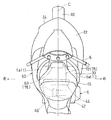
図3に示すように、メインフレーム1はヘッドパイプ4から2股に分かれて後方に延びる左右一対のメインフレーム片1a,1aを有している。これら左右一対のメインフレーム片1a,1aの間にキャニスタ69が配置されている。つまり、車体の幅方向の中央部にキャニスタ69が配置されており、キャニスタ69の一部が車体の中心線C上にある。キャニスタ69の車幅方向外側(左側)を前記吸気ダクト50が通過している。
As shown in FIG. 3, the
キャニスタ69は、少なくとも一部分、ここでは前部を除いた大部分が、平面視で、シリンダヘッド32と重っている。さらに、図3に示す平面視で、燃料タンク15とキャニスタ69が部分的に重なっている。より具体的には、平面視で、燃料タンク15の前部とキャニスタ69の前部を除いた大部分とが重なっている。これにより、燃料タンク15からキャニスタ69までの距離が短くなり、蒸散ガス配管68(図4)が短くて済む。
The
キャニスタ69は、長手方向を有する箱状で、長手方向に直交する断面が矩形であり、長手方向が車幅方向となるように配置される。長手方向が車幅方向以外となるようにキャニスタ69を配置してもよい。図1に示すキャニスタ69の下面69aは、シリンダヘッドカバー33の上面33aに対向して前方に向かって下方に傾斜している。
The
図4は、エンジンEのシリンダヘッド32の周辺を車体右側から見た側面図である。キャニスタ69の位置は、図4のヘッドパイプ4と燃料タンク15との前後方向の隙間Gから燃料タンク15の前部の下方空間にかけての領域S内である。キャニスタ69は、ラジエータ25よりも上方の後方に配置され、キャニスタ69とラジエータ25との間に、遮熱カバー体70が配置されている。これにより、ラジエータファン25aの排風がキャニスタ69に向かうのを阻止できる。また、遮熱カバー体70は、排気ポート35および排気管36とキャニスタ69との上下方向の間のスペースに配置されている。これにより、排気熱がキャニスタ69に伝わるのを防ぐことができる。
FIG. 4 is a side view of the periphery of the
図5に示すように、遮熱カバー体70は、ラジエータ25とシリンダヘッドカバー33との隙間を上方から塞ぐように、ラジエータ25の車幅方向の全範囲の上方を覆っており、ボルト104によりメインフレーム1(図1)に取り付けられている。
As shown in FIG. 5, the heat
図4に示すように、キャニスタ69は、連通路71を構成する連通管72を介してエンジンEの吸気通路45と連通している。この連通管72に制御弁の一種である逆止弁74が設けられている。連通管72および逆止弁74はキャニスタ69の車幅方向外側(右側)に配置されている。逆止弁74は、吸気通路45からキャニスタ69への流体の流れを阻止し、キャニスタ69から吸気通路45への流体の流れを許容する。これらキャニスタ69、連通管72および逆止弁74により燃料タンク15の蒸散ガス処理装置75が構成されている。
As shown in FIG. 4, the
燃料タンク15内部とキャニスタ69とを接続する蒸散ガス配管68、およびキャニスタ69の大気開放側には、逆止弁は設けられていない。図3に示すように、左右のメインフレーム片1a,1aの間で、燃料タンク15から蒸散ガス処理装置75を介してスロットルボディ44に至るシステムが完結している。
A check valve is not provided on the
図4に示すように、キャニスタ69は、上側ブラケット84および下側ブラケット86を介してヘッドパイプ4に支持されている。詳細には、キャニスタ69が、上側ブラケット84および下側ブラケット86に係止されたダンパボックス88に装着され、上側ブラケット84および下側ブラケット86がボルト108により、ヘッドパイプ4に溶接で固着された上側ステー90および下側ステー92にそれぞれ支持されている。ダンパボックス88はゴムのような弾性体からなり、図5に示すように、キャニスタ69における車体幅方向の中央部の外周を抱持して、ヘッドパイプ4からの振動を吸収する。
As shown in FIG. 4, the
このように、図4のキャニスタ69をエンジンEから上方に離間させた位置で、ヘッドパイプ4に支持することで、エンジンEからの熱の影響を小さくするとともに、エンジンEの振動がキャニスタ69に直接伝わるのを抑制できる。
As described above, the
図6に示すように、下側ブラケット86は、エンジンEの2次エア用配管94の支持も兼ねている。2次エア用配管94は、排気ガスの完全燃焼のために排気ポート35(図4)に新鮮な空気を導入するもので、本実施形態では、吸気チャンバ52内の高圧空気をエンジンEの2次空気注入室(図示せず)に噴射する。このように、下側ブラケット86がキャニスタ69の支持と2次エア用配管94の支持とを兼用することで、部品点数が増加するのを抑制できる。
As shown in FIG. 6, the
逆止弁74は、弁ブラケット96を介して、2次空気注入室(図示せず)を覆う注入室カバー98に支持されている。詳細には、弁ブラケット96と注入室カバー98とがボルト110によりシリンダヘッドカバー33の上面に共締めされ、逆止弁74が締結部材112によって弁ブラケット96に取り付けられている。
The
さらに、弁ブラケット96に、エンジンEへの2次空気の供給/遮断を切り替える開閉弁114が、締結部材116によって取り付けられている。このように、共通の弁ブラケット96に逆止弁74および開閉弁114を取り付けるとともに、弁ブラケット96を注入室カバー98ともにシリンダヘッドカバー33に共締めすることで、部品点数の増加が抑制される。弁ブラケット96、上側および下側ブラケット84,86は、シリンダヘッドカバー33における点火プラグ口を避けた位置に支持される。これにより、点火プラグの交換が容易になる。
Further, an opening /
図4に示すように、連通管72は、スロットルボディ44と逆止弁74とを連通する第1連通管120と、逆止弁74とキャニスタ69とを連通する第2連通管122とを有している。第1連通管120の一端120aがスロットルボディ44を介してエンジンEに支持され、他端120bが逆止弁74および弁ブラケット96を介してエンジンEに支持されている。このように、第1連通管120の両端120a,120bがエンジンEに支持される。
As shown in FIG. 4, the
第1連通管120は、スロットルボディ44の吸気通路45における下流側に接続されている。これにより、スロットルバルブ43(図7)が閉じた場合に負圧になりやすく、吸気がキャニスタ69側に流れるのを防ぐことができる。また、第1連通管120は、メインインジェクタ47の噴射口に対向しない位置に接続される。これにより、メインインジェクタ47から噴射された燃料が連通路71に向かうのを回避できる。
The
図8に示すように、逆止弁74は、吸気通路45に連通する吸気側連通孔124と、キャニスタ69に連通するキャニスタ側連通孔126と、両連通孔124,126間を区画するとともに両連通孔124,126を連通する弁口128が設けられた隔壁130と、弁口128を開閉する弁体132とを有している。弁体132は、弁口128を閉じる着座位置P1(図8の実線)と、弁口128を開く非着座位置P2(図8の二点鎖線)との間を移動可能で、着座位置P1では吸気通路45側(図8の上側)からキャニスタ69側(図8の下側)に移動して弁口128を閉じる。つまり、この実施形態では、自動二輪車に搭載した状態で、弁口128が弁体132の下方に位置している。
As shown in FIG. 8, the
逆止弁74は、通電による電磁力によって弁体132を開方向に駆動する電磁弁であり、弁体132を非着座位置P2に向かう方向(上方)に移動させる駆動部Mと、着座位置P1に向かう方向(下方)に付勢する付勢体134とを備えている。つまり、駆動部Mは、通電することにより付勢体134の付勢力に抗して、非着座位置P2に弁体132を移動させる。通電がなくなると、付勢体134の付勢力により弁体132は着座位置P1に移動する。
The
電磁弁としたことで、弁の一次側と二次側の圧力差に関係なく、コントロールユニットCUからの指令によって任意のタイミングで連通路71を開閉できる。これにより、エンジン回転数、スロットル開度、吸気通路の圧力等のコントロールユニットCUに入力される情報に基づいて、弁体132の開閉時期を制御することができる。例えば、所定の燃料噴射量に対する排気ガス成分を判断する時期においては、連通路71を閉じるように制御して、蒸散ガスGの混入による誤差を防ぐことができる。また、蒸散ガスGの混入が走行フィーリングに影響を与える領域を除いて、連通路71を開くように制御することで、走行フィーリングが低下することを防ぎつつ、蒸散ガスGを吸気Iに混入させることができる。
By using the electromagnetic valve, the
また、コントロールユニットCUを用いて、デューティ制御(PWM制御)により逆止弁74の平均的な開度量を調整してもよい。このようなデューティ制御を行うことで、吸気通路45に導入される蒸散ガスGの量を効果的に調整できるので、蒸散ガスGを吸気通路45に導入したことによる空燃比の乱れが抑制される。
Moreover, you may adjust the average opening amount of the
逆止弁74は、通電しない状態では、弁体132が弁口128を閉止しており、通常の機械式の逆止弁として作動する。ここでは、逆止弁74は電磁弁としても作用し、非着座位置P2に弁体132を移動させる通電条件は、例えばつぎのとおりである。
When the
吸気通路45が負圧、すなわち大気圧よりも低くなる負圧条件と、エンジンが安定した状態であることを示す安定条件とを満足すると、コントロールユニットCUは開弁指令を出す。本実施形態では、負圧条件と安定条件の両方を満たすことで開弁指令を出しているが、少なくとも負圧条件を満たすことで開弁指令を出すようにしてもよい。負圧条件と安定条件の両方を満足させることで、蒸散ガスGを吸気通路45に導入したことによる空燃比の乱れを抑制できる。さらに、開弁指令と同時に、メインインジェクタ47の燃料噴射量を少なくすることで、蒸散ガスGを吸気通路45に導入したことにより空燃比がリッチ状態になるのを抑制できる。また、空燃比センサが設けられる場合、空燃比センサの検出信号に基づいて、開弁時の燃料噴射量を調整することで、所望の空燃比に精度よく調整することができる。
When the
本実施形態の前記安定条件は、つぎの(1)〜(6)のすべてが満たされることである。ただし、下記(1)〜(6)の少なくとも一つが満たされることを安定条件としてもよく、下記(1)〜(6)以外の条件を用いてもよい。
(1)エンジン始動から所定時間経過した。
(2)スロットル弁43の開度が所定値以上。
(3)スロットル弁43の開度変化が所定範囲内。
(4)エンジンEの冷却水の温度が所定値以上。
(5)車速が所定値以上。
(6)トランスミッションのギヤが入っている(駆動輪へエンジン動力を伝達可能な状態)。
The stability condition of the present embodiment is that all of the following (1) to (6) are satisfied. However, the stability condition may be that at least one of the following (1) to (6) is satisfied, and conditions other than the following (1) to (6) may be used.
(1) A predetermined time has elapsed since the engine was started.
(2) The opening degree of the
(3) The change in the opening of the
(4) The cooling water temperature of the engine E is equal to or higher than a predetermined value.
(5) The vehicle speed is equal to or higher than a predetermined value.
(6) The gear of the transmission is engaged (a state in which engine power can be transmitted to the drive wheels).
例えば、排気管に空燃比センサが設けられる場合、空燃比センサの検出値を安定条件として用いることができる。この場合、エンジンEの冷却水の温度が所定範囲内で、且つ変速比毎に設定されるエンジン回転数が範囲内であるときの、空燃比センサの検出値を用いることが好ましい。 For example, when an air-fuel ratio sensor is provided in the exhaust pipe, the detected value of the air-fuel ratio sensor can be used as a stable condition. In this case, it is preferable to use the detected value of the air-fuel ratio sensor when the temperature of the cooling water of the engine E is within a predetermined range and the engine speed set for each gear ratio is within the range.
本実施形態の前記負圧条件は、下記の(7)〜(8)の少なくとも一方を満たすことである。
(7)吸気通路の吸気圧が負圧。
(8)エンジンの回転数が所定値以下。
The negative pressure condition of the present embodiment is to satisfy at least one of the following (7) to (8).
(7) The intake pressure in the intake passage is negative.
(8) The engine speed is not more than a predetermined value.
上記(7)の吸気通路の圧力は、例えば、スロットルボディ44の吸気通路45の圧力を検出する吸気圧センサの検出値を用いることが好ましい。あるいは、吸気チャンバ52の圧力を検出するチャンバ圧センサの検出値を用いてもよい。
As the pressure in the intake passage (7), for example, a detection value of an intake pressure sensor that detects the pressure in the
上記(8)のエンジンの回転数が所定値以下である場合は、エンジンEによる吸気吸引力が大きく、吸気通路45が負圧になりやすい。また、エンジン回転数に加えて、スロットル開度も考量して、負圧条件を設定することが好ましい。例えば、スロットル開度が小さい場合、吸気通路45におけるスロットル弁43よりも上流側が正圧であっても、スロットル弁43の下流側が負圧になることがある。したがって、スロットル開度とエンジン回転数の両方に基づいて負圧条件を設定することで、精度よく負圧状態を判定することができる。
When the engine speed of (8) is equal to or less than a predetermined value, the intake suction force by the engine E is large and the
図7に示すように、蒸散ガス処理装置75は、駆動部Mの異常を検出する異常検出部136と、異常検出部136が駆動部Mの異常を検出したときに吸気通路45内の圧力上昇を抑制する圧力調整装置の一種である前記スロットル弁43とを備えている。第1連通管120は吸気通路45におけるスロットル弁43の下流側に連通している。
As shown in FIG. 7, the transpiration
スロットル弁43は、異常検出部136が駆動部Mの異常を検出したときに吸気通路45を閉止する。これにより、吸気通路45におけるスロットル弁43よりも下流側の圧力が上昇するのを抑制して、吸気通路45からキャニスタ69への逆流を防止する。逆止弁74およびスロットル弁43の制御は、車両に搭載された制御装置の一種であるコントロールユニットCUからの制御指令に基づいて行われる。
The
異常検出部136が駆動部Mの異常を検出すると、メータユニット27(図1)に異常表示する。異常検出部136による異常検知は、駆動部Mの抵抗値、電流値、電圧値等の変化により公知の方法で行われる。異常検知、圧力調整は、自動二輪車の停止中または低速時に行われる。これにより、スロットル弁43による圧力調整を行った場合に、走行フィーリングへの影響を小さくできる。また、圧力調整時に、徐々に圧力を変動させることでも、走行フィーリングに与える影響を小さくできる。
When the
圧力調整は、スロットル弁43による吸気量制御のほかの手段による出力制御を用いてエンジン回転数を低下させてもよい。具体的には、異常検出部136が駆動部Mの異常を検出すると、インジェクタによる燃料噴射量が正常時に比べて少なくなるように制御する。例えば、メインインジェクタ47の燃料噴射量を少なくするか、あるいはこれに代えて異常検出部136の異常検出時に、トップインジェクタ53(図2)の燃料噴射を停止するようにしてもよい。また、メインインジェクタ47は、異常検出部136が駆動部Mの異常を検出した状態でも、吸気の負圧を維持できる範囲内で、運転者の操作により吸気量制御を操作可能としてもよい。さらに、サブスロットル弁を備えている場合、サブスロットル弁により吸気量制御を行ってもよい。
In the pressure adjustment, the engine speed may be decreased by using output control by means other than intake air amount control by the
図1の過給機42の性能を調整できる場合は、過給機42の性能を低下させて吸気圧力の上昇を抑制してもよい。具体的には、変速機や可変速モータにより過給機42の回転数を変えることで過給機42の性能を調整できる。また、図2のリリーフ弁80を開制御することで、吸気圧力の上昇を抑制してもよい。リリーフ弁80を開制御とエンジン回転数制御を併用することが好ましい。
When the performance of the
図9は、蒸散ガス処理装置75の異常時の制御方法を示すフロー図である。同制御方法は、異常検知工程S1と圧力抑制工程S2とを備えている。異常検知工程S1では、異常検出部136により制御弁の一種である逆止弁74の異常が検知される。
FIG. 9 is a flowchart showing a control method when the transpiration
圧力抑制工程S2では、異常検知工程S1において異常が検知されたときに、スロットル弁43(圧力調整装置)により、吸気通路45内の圧力上昇を抑制する。圧力抑制工程S2は異常が復帰するまで繰り返される。これにより、吸気通路45からキャニスタ69への逆流を防止できる。異常検知は、ライダーによる始動指令後の動作チェック時に行われてもよい。これにより、過給前の状態で出力抑制が行われるから、キャニスタ69への吸気Iの流入を確実に防ぐことができる。
In the pressure suppression step S2, when an abnormality is detected in the abnormality detection step S1, a pressure increase in the
また、図9の異常時の制御方法は、吸気通路45とキャニスタ69とを接続する連通路71に、逆止弁74に代えて、開動作/閉動作をともに電動で行う電動制御弁を配置した場合にも適用できる。
In addition, the control method in the event of an abnormality in FIG. 9 is provided with an electric control valve that electrically opens and closes the
過給機42を搭載したエンジンでは、図7に示す吸気通路45が正圧になることがある。この場合、吸気通路45と連通路71との間に逆止弁74がないと、高圧の吸気Iがキャニスタ69に流入するので、キャニスタ69が変形しないように、キャニスタ69の構造の変更を検討する必要がある。
In an engine equipped with the
上記構成によれば、吸気通路45とキャニスタ69とを連通する連通路71に逆止弁74が設けられ、この逆止弁74により吸気通路45からキャニスタ69への流体の流れが阻止される。したがって、過給機42による過給により吸気通路45が正圧になった場合でも、キャニスタ69に吸気Iが流れ込むのを防ぐことができる。また、逆止弁74は、吸気通路45が負圧の場合または燃料タンク15側よりも低圧の場合、キャニスタ69から吸気通路45への流体の流れは許容する。これにより、キャニスタ69に2系統の配管68,120bを接続し、1つの弁74を設けた簡単な構造で、キャニスタ69の構造を変更することなく、蒸散ガスGの処理および逆流の防止を実現できる。
According to the above configuration, the
図8に示すように、弁体132が吸気通路側からキャニスタ側に移動して弁口128を閉じるので、吸気通路45が正圧になった場合に、キャニスタ69に吸気Iが流れ込むのを確実に防ぐことができる。
As shown in FIG. 8, since the
逆止弁74は、コントロールユニットCU(図7)からの制御指令に基づいて弁体132を移動させる駆動部Mを備えているので、逆止弁と電磁弁とが一体化されて部品点数を抑えることができる。また、電磁弁を用いることで、任意のタイミングで弁を開閉することができる。
Since the
さらに、逆止弁74は、着座位置P1に向かう方向に付勢する付勢体136を備え、駆動部Mは、通電することにより付勢体136の付勢力に抗して、非着座位置P2に弁体132を移動させる。これにより、非通電時でも付勢体136の付勢力により弁口128を閉じることができる。したがって、通電不能な異常状態でも、逆止弁として作用し、不所望に開弁するのを防いで、キャニスタ側に吸気が流れ込むのを防ぐことができる。
Furthermore, the
自動二輪車に搭載した状態で、弁口128が弁体132の下方に位置している。これにより、弁体132の自重により閉弁する方向に力が作用するので、付勢体136の付勢力を小さくできる。
The
図7に示す異常検出部136が駆動部Mの異常を検出したときに吸気通路45内の圧力上昇を抑制する圧力調整装置(スロットル弁)43を備えているので、通電解除ができない異常状態となった場合でも、スロットル弁43を絞ることで、吸気通路45の圧力の上昇を抑えて、キャニスタ69に吸気Iが流れ込むのを抑制できる。
Since the
また、異常検出部136が駆動部Mの異常を検出した状態でも、運転者の操作によりスロットル弁43を操作可能とすれば、異常検出後も運転者の操作によりエンジンの出力を調整できる。
Further, even if the
異常検出部136が駆動部Mの異常を検出すると、メインインジェクタ47の燃料噴射量が少なくなるように制御されるので、異常検出後に吸気通路45が絞られた状態でも、空燃比がリッチになるのを防ぐことができる。
When the
図1に示すように、エンジンEの上方でヘッドパイプ4と燃料タンク15との間にキャニスタ69が配置されているので、キャニスタ69から燃料タンク15およびスロットルボディ44までの距離が短くなる。したがって、図4に示すキャニスタ69に接続される配管72,68が短くなるので、これらの配管72,68の取り回しが容易である。また、第1連通管120の両端120a,120bがエンジンEに支持されているので、第1連通管120を安定して支持できるとともに、エンジンEの組立てと同時に第1連通管120もエンジンEに組み込まれるので、車体にエンジンを組み付けたのち第1連通管120を車体とにエンジンEの両方に組み付ける必要がなくなり、第1連通管120の車体への取付けが容易になる。
As shown in FIG. 1, since the
図3に示す左右一対のメインフレーム片1a,1aの間にキャニスタ69が配置されているので、ヘッドパイプ4の後方で左右のメインフレーム片1a,1aの間の空いた空間にキャニスタ69を配置できる。
Since the
キャニスタ69は、平面視で、エンジンEのシリンダヘッド32と重なる領域に配置されている。これにより、キャニスタ69からスロットルボディ44までの距離が短くなるので、連通管72が短くなる。これにより、連通管72の取り回しが容易になる。特に、蒸散ガス用の配管は、蒸散ガスが抜けないように加工が施された硬くて高価なゴムチューブで構成されるので、配管が短くなることによる費用効果が大きく、且つ、取り回しが容易になる効果も大きい。
The
キャニスタ69は、長手方向を有する矩形の箱状であり、長手方向が車幅方向となるように配置されている。これにより、キャニスタ69の前後方向および上下方向の寸法が小さくなるので、キャニスタ69を配置しやすい。
The
図1に示すシリンダヘッドカバー33の上面が前方に向かって下方に傾斜し、キャニスタ69の下面が、シリンダヘッドカバー33の上面に対向して前方に向かって下方に傾斜している。これにより、キャニスタ69をシリンダヘッドカバー33の上方に配置しつつ、キャニスタ69と高温のシリンダヘッドカバー33との距離を確保しやすい。
The upper surface of the
キャニスタ69は、図4に示すラジエータ25の後方に配置され、キャニスタ69とラジエータ25との間に、遮熱カバー体70が配置されているので、ラジエータ25の排風からキャニスタ69が保護される。
The
キャニスタ69は、図1に示す吸気チャンバ52の前方に配置され、キャニスタの車幅方向外側(左側)を吸気ダクト50が通過している。そのため、吸気チャンバ52内のラム圧を利用して吸気効率を向上させることができるとともに、吸気ダクト50とキャニスタ69との干渉を防ぐことができる。連通管72は、キャニスタの右側に配置されているので、連通管72と吸気ダクト50との干渉を回避できる。
The
本発明は、以上の実施形態に限定されるものでなく、本発明の要旨を逸脱しない範囲内で、種々の追加、変更または削除が可能である。例えば、上記実施形態では、逆止弁74がエンジンEに支持されることで、第1連通管120の両端がエンジンに支持されるようにしていたが、キャニスタ69をエンジンEに支持することで、連通管72の両端がエンジンに支持されるようにしてもよい。また、逆止弁74は、駆動部Mを備えていない公知の機械式の逆止弁でもよい。
The present invention is not limited to the above-described embodiment, and various additions, modifications, or deletions can be made without departing from the gist of the present invention. For example, in the above embodiment, the
さらに、スロットルボディ44の前部に、連通路71が接続されてもよい。また、過給機42はクランク軸26の動力で駆動される機械式スーパーチャージャーのほか、排気ガスの内部エネルギーで駆動されるターボ式スーパーチャージャーであってもよい。上記実施形態では、電子制御スロットルシステムを採用しているが、電子制御スロットルシステムでなくてもよい。
Further, a
また、本発明は、自動二輪車に限定されず、三輪車、四輪バギー等の車両にも適用できる。ただし、以下の理由から、本発明は自動二輪車に特に有効である。すなわち、自動二輪車は、車幅方向寸法が小さいので、キャニスタの配置スペースが限られており、吸気通路に近接した位置にキャニスタが配置される。そのため、過給機を搭載したエンジンの場合、吸気がキャニスタに流入しやすくなる。また、自動二輪車は比較的軽量であるので、エンジン回転数が急上昇しやすい。これにより吸気通路の内圧も上昇しやすくなり、吸気がキャニスタに流入しやすくなる。よって、本発明は自動二輪車に特に有効である。したがって、そのようなものも本発明の範囲内に含まれる。 Further, the present invention is not limited to motorcycles, and can be applied to vehicles such as tricycles and four-wheel buggies. However, the present invention is particularly effective for motorcycles for the following reasons. That is, since the motorcycle has a small size in the vehicle width direction, the arrangement space of the canister is limited, and the canister is arranged at a position close to the intake passage. Therefore, in the case of an engine equipped with a supercharger, intake air easily flows into the canister. In addition, since the motorcycle is relatively light, the engine speed tends to increase rapidly. As a result, the internal pressure of the intake passage is likely to increase, and the intake air easily flows into the canister. Therefore, the present invention is particularly effective for motorcycles. Therefore, such a thing is also included in the scope of the present invention.
15 燃料タンク
42 過給機
43 スロットル弁(圧力調整装置)
45 吸気通路
47 メインインジェクタ(燃料噴射装置)
65 吸着体
69 キャニスタ
71 連通路
74 逆止弁
75 蒸散ガス処理装置
124 吸気側連通孔
126 キャニスタ側連通孔
128 弁口
130 隔壁
132 弁体
134 付勢体
136 異常検出部
CU コントロールユニット(車両制御装置)
E エンジン
G 蒸散ガス
M 駆動部
P1 着座位置
P2 非着座位置
15
45
65
E Engine G Transpiration gas M Drive part P1 Seating position P2 Non-sitting position
Claims (6)
前記燃料タンクからの蒸散ガスを吸着する吸着体を収容するキャニスタと、
前記エンジンの吸気通路と前記キャニスタとを連通する連通路と、
前記連通路に設けられて前記吸気通路から前記キャニスタへの流体の流れを阻止し、前記キャニスタから前記吸気通路への流体の流れを許容する逆止弁と、
車両制御装置からの制御指令に基づいて、前記逆止弁の弁体を移動させる駆動部と、
前記駆動部の異常を検出する異常検出部と、
前記異常検出部が前記駆動部の異常を検出したときに、前記吸気通路内の圧力上昇を抑制する圧力調整装置と、を備え、
前記圧力調整装置は、前記吸気通路における前記過給機と前記吸気側連通孔との間に配置された電磁開閉弁であり、
前記電磁開閉弁は、前記異常検出部が前記駆動部の異常を検出したときに、前記吸気通路が閉じる方向へ変位し、
前記電磁開閉弁は、前記異常検出部が前記駆動部の異常を検出した状態で、運転者の操作により開度調整可能に構成されている蒸散ガス処理装置。 A fuel tank transpiration gas treatment device used in a vehicle equipped with an engine having a supercharger,
A canister that houses an adsorbent that adsorbs the vaporized gas from the fuel tank;
A communication passage communicating the intake passage of the engine and the canister;
A check valve provided in the communication passage to prevent a fluid flow from the intake passage to the canister and to allow a fluid flow from the canister to the intake passage;
Based on a control command from the vehicle control device, a drive unit that moves the valve body of the check valve;
An abnormality detection unit for detecting an abnormality of the drive unit;
A pressure adjusting device that suppresses a pressure increase in the intake passage when the abnormality detection unit detects an abnormality of the drive unit;
The pressure adjusting device is an electromagnetic on-off valve disposed between the supercharger and the intake side communication hole in the intake passage,
The electromagnetic on-off valve is displaced in a direction in which the intake passage is closed when the abnormality detection unit detects an abnormality of the drive unit,
The electromagnetic on-off valve is a transpiration gas processing apparatus configured such that the opening degree can be adjusted by a driver's operation in a state in which the abnormality detecting unit detects an abnormality of the driving unit.
前記弁体は、前記弁口を閉じる着座位置と前記弁口を開く非着座位置との間を移動可能で、前記着座位置では前記吸気通路側から前記キャニスタ側に移動して前記弁口を閉じる蒸散ガス処理装置。 2. The transpiration gas processing apparatus according to claim 1, wherein the check valve defines an intake side communication hole communicating with the intake passage, a canister side communication hole communicating with the canister, and both communication holes. A partition wall provided with a valve port for communicating with the communication hole, and a valve body for opening and closing the valve port,
The valve body is movable between a seating position for closing the valve port and a non-sitting position for opening the valve port, and moves from the intake passage side to the canister side at the seating position to close the valve port. Transpiration gas processing equipment.
前記駆動部は、通電することにより前記付勢体の付勢力に抗して、前記非着座位置に前記弁体を移動する蒸散ガス処理装置。 The transpiration gas processing apparatus according to claim 1 , further comprising a biasing body that biases the valve body in a direction toward the seating position,
The drive unit is a transpiration gas processing apparatus that moves the valve body to the non-sitting position against the urging force of the urging body by energizing.
前記燃料タンクからの蒸散ガスを吸着する吸着体を収容するキャニスタと、
前記エンジンの吸気通路と前記キャニスタとを連通する連通路と、
前記連通路に設けられて前記吸気通路から前記キャニスタへの流体の流れを阻止し、前記キャニスタから前記吸気通路への流体の流れを許容する逆止弁と、
車両制御装置からの制御指令に基づいて、前記逆止弁の弁体を移動させる駆動部と、を備え、
前記連通路は、前記吸気通路の一部を構成するスロットルボディに接続され、
前記スロットルボディに、吸気量を調整するスロットルバルブと、前記スロットルバルブの下流で前記吸気通路に燃料を噴射する燃料噴射装置が設けられ、
前記連通路は、前記吸気通路における前記燃料噴射装置の噴射口に対向しない位置に接続され、
前記逆止弁は、前記吸気通路に連通する吸気側連通孔と、前記キャニスタに連通するキャニスタ側連通孔と、両連通孔間を区画するとともに両連通孔を連通する弁口が設けられた隔壁と、前記弁口を開閉する前記弁体とを有し、
前記弁体は、前記弁口を閉じる着座位置と前記弁口を開く非着座位置との間を移動可能で、前記着座位置では前記吸気通路側から前記キャニスタ側に移動して前記弁口を閉じ、
前記車両制御装置からの制御指令は、エンジン回転数、スロットル開度および前記吸気通路の圧力の少なくも一つに基づいて送信され、
前記車両制御装置からの制御指令は、前記吸気通路が大気圧よりも低くなる負圧条件と、エンジンが安定した状態であることを示す安定条件のうち少なくとも負圧条件が満たされたときに出され、
前記安定条件は、エンジン始動から所定時間経過、前記スロットルバルブの開度が所定値以上、前記スロットルバルブの開度変化が所定範囲内、エンジンの冷却水の温度が所定値以上、車速が所定値以上またはトランスミッションのギヤが入っているうちの少なくとも一つを含む蒸散ガス処理装置。 A fuel tank transpiration gas treatment device used in a vehicle equipped with an engine having a supercharger,
A canister that houses an adsorbent that adsorbs the vaporized gas from the fuel tank;
A communication passage communicating the intake passage of the engine and the canister;
A check valve provided in the communication passage to prevent a fluid flow from the intake passage to the canister and to allow a fluid flow from the canister to the intake passage;
A drive unit that moves the valve body of the check valve based on a control command from the vehicle control device;
The communication path is connected to a throttle body that forms part of the intake path,
The throttle body is provided with a throttle valve that adjusts an intake air amount, and a fuel injection device that injects fuel into the intake passage downstream of the throttle valve,
The communication path is connected to a position not facing the injection port of the fuel injection device in the intake path,
The check valve includes a suction side communication hole that communicates with the intake passage, a canister side communication hole that communicates with the canister, and a partition wall that partitions the communication holes and communicates the communication holes. And the valve body for opening and closing the valve opening,
The valve body is movable between a seating position for closing the valve port and a non-sitting position for opening the valve port, and moves from the intake passage side to the canister side at the seating position to close the valve port. ,
The control command from the vehicle control device is transmitted based on at least one of the engine speed, the throttle opening, and the pressure of the intake passage,
A control command from the vehicle control device is issued when at least a negative pressure condition is satisfied among a negative pressure condition in which the intake passage is lower than atmospheric pressure and a stable condition indicating that the engine is in a stable state. And
The stability condition is that a predetermined time elapses after the engine is started, the throttle valve opening is a predetermined value or more, the throttle valve opening change is within a predetermined range, the engine coolant temperature is a predetermined value or more, and the vehicle speed is a predetermined value. A transpiration gas treatment device comprising at least one of the above or a gear of the transmission.
Priority Applications (2)
| Application Number | Priority Date | Filing Date | Title |
|---|---|---|---|
| JP2014141081A JP6433179B2 (en) | 2014-07-09 | 2014-07-09 | Evaporative gas treatment equipment for fuel tank |
| US14/741,355 US9695783B2 (en) | 2014-07-09 | 2015-06-16 | Fuel evaporative gas treatment device for fuel tank |
Applications Claiming Priority (1)
| Application Number | Priority Date | Filing Date | Title |
|---|---|---|---|
| JP2014141081A JP6433179B2 (en) | 2014-07-09 | 2014-07-09 | Evaporative gas treatment equipment for fuel tank |
Publications (3)
| Publication Number | Publication Date |
|---|---|
| JP2016017468A JP2016017468A (en) | 2016-02-01 |
| JP2016017468A5 JP2016017468A5 (en) | 2017-06-08 |
| JP6433179B2 true JP6433179B2 (en) | 2018-12-05 |
Family
ID=55067240
Family Applications (1)
| Application Number | Title | Priority Date | Filing Date |
|---|---|---|---|
| JP2014141081A Active JP6433179B2 (en) | 2014-07-09 | 2014-07-09 | Evaporative gas treatment equipment for fuel tank |
Country Status (2)
| Country | Link |
|---|---|
| US (1) | US9695783B2 (en) |
| JP (1) | JP6433179B2 (en) |
Families Citing this family (8)
| Publication number | Priority date | Publication date | Assignee | Title |
|---|---|---|---|---|
| WO2014185091A1 (en) * | 2013-05-17 | 2014-11-20 | 川崎重工業株式会社 | Air intake chamber for saddled vehicle |
| JP6220210B2 (en) * | 2013-10-01 | 2017-10-25 | 川崎重工業株式会社 | Motorcycle |
| JP6580401B2 (en) * | 2015-07-15 | 2019-09-25 | 愛三工業株式会社 | Canister |
| JP2017105286A (en) * | 2015-12-08 | 2017-06-15 | スズキ株式会社 | Saddle-riding type vehicle |
| US10486762B2 (en) * | 2017-04-26 | 2019-11-26 | Ktm Ag | Motorcycle having an internal combustion engine and a container for receiving fuel vapor from the fuel tank |
| JP2022184241A (en) * | 2021-05-31 | 2022-12-13 | ヤマハ発動機株式会社 | Saddle-riding type vehicle |
| JP2022184240A (en) | 2021-05-31 | 2022-12-13 | ヤマハ発動機株式会社 | Saddle riding type vehicle |
| JP2022184239A (en) * | 2021-05-31 | 2022-12-13 | ヤマハ発動機株式会社 | Saddle-riding type vehicle |
Family Cites Families (14)
| Publication number | Priority date | Publication date | Assignee | Title |
|---|---|---|---|---|
| JP2690977B2 (en) * | 1988-03-18 | 1997-12-17 | 株式会社日立製作所 | Electronically controlled throttle valve for internal combustion engine |
| JPH0481558A (en) * | 1990-07-23 | 1992-03-16 | Aisan Ind Co Ltd | Canister purge controller |
| CN1070995C (en) * | 1995-05-19 | 2001-09-12 | 西门子加拿大有限公司 | Canister purge system having improved purge valve control |
| SE522391C2 (en) * | 2000-01-26 | 2004-02-03 | Volvo Personvagnar Ab | Crankcase and exhaust ventilation in a supercharged internal combustion engine |
| DE10236387A1 (en) * | 2002-08-08 | 2004-02-19 | Robert Bosch Gmbh | Device for the metered admixture of volatilized fuel in an intake pipe of an internal combustion engine |
| US6814061B2 (en) * | 2002-09-24 | 2004-11-09 | Siemens Vdo Automotive Inc. | Unipolar canister purge valve |
| JP2005036757A (en) | 2003-07-17 | 2005-02-10 | Honda Motor Co Ltd | Evaporated fuel processing device |
| JP4249160B2 (en) * | 2005-07-19 | 2009-04-02 | 本田技研工業株式会社 | Backflow prevention valve failure detection device |
| JP2008075599A (en) * | 2006-09-22 | 2008-04-03 | Toyota Motor Corp | Failure diagnostic device of internal combustion engine |
| JP5078700B2 (en) * | 2008-03-28 | 2012-11-21 | 本田技研工業株式会社 | Multi-cylinder engine intake system |
| US8312765B2 (en) * | 2009-03-06 | 2012-11-20 | Ford Global Technologies, Llc | Fuel vapor purging diagnostics |
| US20110197864A1 (en) * | 2010-02-17 | 2011-08-18 | Rolf Karcher | Internal combustion engine and method for monitoring a tank ventilation system and a crankcase ventilation system |
| US8973558B2 (en) * | 2011-02-22 | 2015-03-10 | Ford Global Technologies, Llc | Method and system for fuel vapor control |
| US9109550B2 (en) * | 2012-04-06 | 2015-08-18 | Ford Global Technologies, Llc | Modular design for fuel vapor purging in boosted engines |
-
2014
- 2014-07-09 JP JP2014141081A patent/JP6433179B2/en active Active
-
2015
- 2015-06-16 US US14/741,355 patent/US9695783B2/en active Active
Also Published As
| Publication number | Publication date |
|---|---|
| US20160010599A1 (en) | 2016-01-14 |
| JP2016017468A (en) | 2016-02-01 |
| US9695783B2 (en) | 2017-07-04 |
Similar Documents
| Publication | Publication Date | Title |
|---|---|---|
| JP6433179B2 (en) | Evaporative gas treatment equipment for fuel tank | |
| JP6309379B2 (en) | Motorcycle | |
| EP2489849B1 (en) | Engine supercharging device | |
| US9957928B2 (en) | Supercharging system for engine | |
| JP6561771B2 (en) | Saddle riding vehicle | |
| JP4732272B2 (en) | Intake system structure of a V-type internal combustion engine for motorcycles | |
| JP2019043242A (en) | Canister structure of saddle-riding type vehicle | |
| US10294854B2 (en) | Saddle-ridden vehicle | |
| JP2010059942A (en) | Engine, and vehicle provided with the same | |
| EP2604829B1 (en) | Intake control device | |
| JP6711088B2 (en) | Saddle type vehicle | |
| WO2014185090A1 (en) | Air intake chamber for saddled vehicle | |
| JP6221126B2 (en) | Intake system structure for saddle-ride type vehicles | |
| JP2012180804A (en) | Emission control device of saddle-ride type vehicle | |
| JP5355673B2 (en) | engine | |
| JP5856215B2 (en) | Saddle riding vehicle | |
| JP5869611B2 (en) | Saddle riding vehicle | |
| JP7305696B2 (en) | straddle-type vehicle | |
| JP5874244B2 (en) | Secondary air supply device for internal combustion engine | |
| JP2003097392A (en) | Injector arrangement structure of fuel injection engine | |
| JP6657776B2 (en) | Saddle-type vehicle | |
| WO2020071295A1 (en) | Saddle-type vehicle | |
| JP2015074986A (en) | Supercharging system of internal combustion engine | |
| JP5977704B2 (en) | vehicle | |
| JP2019210892A (en) | engine |
Legal Events
| Date | Code | Title | Description |
|---|---|---|---|
| A521 | Request for written amendment filed |
Free format text: JAPANESE INTERMEDIATE CODE: A523 Effective date: 20170418 |
|
| A621 | Written request for application examination |
Free format text: JAPANESE INTERMEDIATE CODE: A621 Effective date: 20170418 |
|
| A977 | Report on retrieval |
Free format text: JAPANESE INTERMEDIATE CODE: A971007 Effective date: 20180226 |
|
| A131 | Notification of reasons for refusal |
Free format text: JAPANESE INTERMEDIATE CODE: A131 Effective date: 20180306 |
|
| A521 | Request for written amendment filed |
Free format text: JAPANESE INTERMEDIATE CODE: A523 Effective date: 20180409 |
|
| A131 | Notification of reasons for refusal |
Free format text: JAPANESE INTERMEDIATE CODE: A131 Effective date: 20180710 |
|
| A521 | Request for written amendment filed |
Free format text: JAPANESE INTERMEDIATE CODE: A523 Effective date: 20180726 |
|
| TRDD | Decision of grant or rejection written | ||
| A01 | Written decision to grant a patent or to grant a registration (utility model) |
Free format text: JAPANESE INTERMEDIATE CODE: A01 Effective date: 20181030 |
|
| A61 | First payment of annual fees (during grant procedure) |
Free format text: JAPANESE INTERMEDIATE CODE: A61 Effective date: 20181106 |
|
| R150 | Certificate of patent or registration of utility model |
Ref document number: 6433179 Country of ref document: JP Free format text: JAPANESE INTERMEDIATE CODE: R150 |
|
| S111 | Request for change of ownership or part of ownership |
Free format text: JAPANESE INTERMEDIATE CODE: R313111 |
|
| R350 | Written notification of registration of transfer |
Free format text: JAPANESE INTERMEDIATE CODE: R350 |
|
| R250 | Receipt of annual fees |
Free format text: JAPANESE INTERMEDIATE CODE: R250 |