JP6428718B2 - Game machine - Google Patents
Game machine Download PDFInfo
- Publication number
- JP6428718B2 JP6428718B2 JP2016141352A JP2016141352A JP6428718B2 JP 6428718 B2 JP6428718 B2 JP 6428718B2 JP 2016141352 A JP2016141352 A JP 2016141352A JP 2016141352 A JP2016141352 A JP 2016141352A JP 6428718 B2 JP6428718 B2 JP 6428718B2
- Authority
- JP
- Japan
- Prior art keywords
- speaker
- sound
- unit
- gaming machine
- game
- Prior art date
- Legal status (The legal status is an assumption and is not a legal conclusion. Google has not performed a legal analysis and makes no representation as to the accuracy of the status listed.)
- Active
Links
Images


Description
本発明は、遊技機に関するものである。 The present invention relates to a gaming machine.
例えばパチンコ遊技機等の遊技機においては、遊技者により操作される操作手段を備えているものが知られている。例えば、特許文献1に示すパチンコ遊技機では、遊技機前面に操作手段を設け、遊技者に有利な特別遊技状態等の発生を遊技者に期待させるために、遊技者の操作に応じて特別演出を画面表示等にて行うように構成されている。このように操作手段を採用した遊技機においては、操作手段を用いて遊技者の遊技への注目度を如何にして高めるかが重要な課題となっている。
For example, a gaming machine such as a pachinko gaming machine is known which includes an operation means operated by a player. For example, in the pachinko gaming machine shown in
ここで、単に操作手段の操作に応じて特別演出を行うだけでは、操作が単調になる等して新鮮味が薄れ、操作自体への興味が低下しやすくなると懸念される。つまり、遊技者に操作を促したとしても半ば機械的に操作がなされ、操作手段による遊技への注目度向上機能を上手く発揮させることが困難になると想定される。故に、操作手段を利用して遊技への注目度の向上を図る上では、未だ改善の余地がある。 Here, there is a concern that simply performing a special effect according to the operation of the operation means will make the operation monotonous and the freshness will fade, and the interest in the operation itself will be likely to decrease. That is, even if the player is prompted to perform an operation, it is assumed that the operation is performed halfway and it is difficult to perform the function of improving the degree of attention to the game by the operation means. Therefore, there is still room for improvement in using the operation means to increase the degree of attention to the game.
本発明は、上記例示した事情等に鑑みてなされたものであり、遊技への注目度を好適に高めることが可能な遊技機を提供することを目的とするものである。 The present invention has been made in view of the above-described circumstances, and an object thereof is to provide a gaming machine capable of suitably increasing the degree of attention to a game.
本発明は、
筒状部及び当該筒状部の一端側に形成された操作部を有し、配設対象から前記筒状部の一部及び前記操作部が突出した状態となるように配設され、遊技者により前記操作部が押圧操作されることにより所定方向に変位可能に設けられた操作手段と、
特定状況となった場合に、前記配設対象からの突出量が増えるようにして前記操作手段を前記所定方向とは反対側に移動させる操作量変更手段と
を備え、
前記筒状部は、前記操作量変更手段によって前記操作手段が移動することにより前記配設対象から突出する部分の少なくとも一部を通じて同操作手段の内部領域が視認可能となるように構成されており、
前記操作手段の内部領域において前記操作量変更手段により突出量が増加した場合に視認可能となる特定領域にて表示演出を実行する表示演出手段を備え、
前記操作手段には、少なくとも前記操作量変更手段による前記操作手段の前記移動が行われていない状況下において、当該操作手段に並設された複数の発光部からの光が集まる特定箇所に位置し且つ当該光を拡散させることにより前記一端側からの前記特定領域の視認が困難又は不可となるようにする操作手段側光拡散部が設けられており、
前記操作手段は、前記操作量変更手段によって前記操作手段の前記移動が行われた状況下では、前記操作手段側光拡散部が前記特定箇所から外れることにより、当該移動が行われていない状況下よりも前記操作手段側光拡散部を通じた前記特定領域の視認が容易となるように構成されていることを特徴とする。
The present invention
A cylindrical portion and an operation portion formed on one end side of the cylindrical portion, and arranged so that a part of the cylindrical portion and the operation portion protrude from an arrangement target; Operating means provided so as to be displaceable in a predetermined direction by pressing the operating part by
An operation amount changing means for moving the operation means to the side opposite to the predetermined direction so as to increase the amount of protrusion from the arrangement target when a specific situation occurs;
The cylindrical portion is configured so that an internal region of the operation means can be visually recognized through at least a part of a portion protruding from the arrangement target when the operation means is moved by the operation amount changing means. ,
A display effect means for executing a display effect in a specific area that is visible when the protrusion amount is increased by the operation amount changing means in the internal area of the operation means;
The operating means is located at a specific location where light from a plurality of light emitting units arranged in parallel to the operating means gathers at least in a situation where the movement of the operating means by the operating amount changing means is not performed. and has the operation unit side light-diffusing part you like becomes difficult or impossible viewing of a specific area from the one end side by diffusing the light are provided,
In the situation where the movement of the operation means is performed by the operation amount changing means, the operation means is not moved because the operation means side light diffusing unit is removed from the specific location. Further, the specific area is more easily viewed through the operation means side light diffusing section.
遊技への注目度を好適に高めることができる。 The degree of attention to the game can be suitably increased.
<第1の実施の形態>
以下、遊技機の一種であるパチンコ遊技機(以下、「パチンコ機」という)の第1の実施の形態を、図面に基づいて詳細に説明する。図1はパチンコ機10の正面図、図2及び図3はパチンコ機10の主要な構成を展開して示す斜視図、図4はパチンコ機10の背面図、図5はパチンコ機10の外枠11の斜視図である。なお、図2では便宜上パチンコ機10の遊技領域内の構成を省略している。
<First Embodiment>
Hereinafter, a first embodiment of a pachinko gaming machine (hereinafter referred to as a “pachinko machine”), which is a type of gaming machine, will be described in detail with reference to the drawings. FIG. 1 is a front view of the
外枠11は、木製の板材を四辺に連結し構成されるものであって矩形枠状をなしている。外枠11の下枠部11aの板幅は、左右の枠部11b,11cの板幅に比べ大きくなっており、下枠部11aは左右の枠部11b,11cよりもパチンコ機10前方に延出している。パチンコ機10は、外枠11を島設備に取り付け固定することにより、遊技ホールに設置される。なお、外枠11を合成樹脂やアルミニウム等の金属によって形成することも可能である。
The
外枠11の一側部に遊技機主部12が開閉可能に支持されている。具体的には、図5に示すように、外枠11における上枠部11dと左枠部11bとの連結部分に上側支持用金具17が固定されており、さらに外枠11における下枠部11aと左枠部11bとの連結部分に下側支持用金具18が固定されている。これら上側支持用金具17及び下側支持用金具18により支持機構が構成され、当該支持機構によって外枠11に対して遊技機主部12が回動可能に支持されている。
A gaming machine
遊技機主部12は、本体枠13と、その本体枠13の前方に配置される前扉枠14と、本体枠13の後方に配置される裏パックユニット15とを備えている。遊技機主部12のうち本体枠13が外枠11に対して回動可能に支持されている。詳細には、正面視で左側を回動基端側(開閉基端側)とし右側を回動先端側(開閉先端側)として本体枠13が前方へ回動可能とされている。
The gaming machine
本体枠13には、図2に示すように、前扉枠14が回動可能に支持されており、正面視で左側を回動基端側(開閉基端側)とし右側を回動先端側(開閉先端側)として前方へ回動可能(開閉可能)とされている。また、本体枠13には、図3に示すように、裏パックユニット15が回動可能(開閉可能)に支持されており、正面視で左側を回動基端側(開閉基端側)とし右側を回動先端側(開閉先端側)として後方へ回動可能とされている。
As shown in FIG. 2, a
次に、前扉枠14について説明する。なお、以下の説明では、図1〜図3を参照するとともに、前扉枠14の背面の構成については図6を参照する。図6は前扉枠14の背面図である。
Next, the
前扉枠14は本体枠13の前面側全体を覆うようにして設けられている。前扉枠14には後述する遊技領域のほぼ全域を前方から視認することができるようにした窓部21が形成されている。窓部21は、略楕円形状をなし、透明性を有するガラスパネル22が嵌め込まれている。窓部21の周囲には、各種ランプ等の発光手段が設けられている。例えば、窓部21の周縁に沿ってLED等の発光手段を内蔵した環状電飾部23が設けられている。環状電飾部23では、大当たり時や所定のリーチ時等における遊技状態の変化に応じて点灯や点滅が行われる。また、環状電飾部23の中央であってパチンコ機10の最上部には所定のエラー時に点灯するエラー表示ランプ部24が設けられ、さらにその左右側方には賞球払出中に点灯する賞球ランプ部25が設けられている。
The
また、左右の賞球ランプ部25に近接した位置には、遊技状態に応じた効果音などが出力されるスピーカ部26が設けられている。スピーカ部26の裏面には、図2に示すように、スピーカ28が設けられている。スピーカ28は、その前面をスピーカ部26の裏面に向けて設置されており、スピーカ28からの音は、スピーカ部26を通じてパチンコ機10前方に向けて出力される。
In addition, a
前扉枠14における窓部21の下方には、手前側へ膨出した上側膨出部31と下側膨出部32とが上下に並設されている。上側膨出部31内側には上方に開口した上皿33が設けられており、下側膨出部32内側には同じく上方に開口した下皿34が設けられている。上皿33は、後述する払出装置より払い出された遊技球を一旦貯留し、一列に整列させながら後述する遊技球発射機構側へ導くための機能を有する。また、下皿34は、上皿33内にて余剰となった遊技球を貯留する機能を有する。
Below the
下側膨出部32の右方には、手前側へ突出するようにしてハンドル装置41が設けられている。ハンドル装置41が操作されることにより、後述する遊技球発射機構から遊技球が発射される。
A
前扉枠14の背面には、図2及び図6に示すように、通路形成ユニット50が取り付けられている。通路形成ユニット50は、合成樹脂により成形されており、上皿33に通じる前扉側上皿通路51と、下皿34に通じる前扉側下皿通路52とが形成されている。通路形成ユニット50において、その上側隅部には後方に突出し上方に開放された受口部53が形成されており、当該受口部53を仕切壁54によって左右に仕切ることで前扉側上皿通路51と前扉側下皿通路52の入口部分とが形成されている。前扉側上皿通路51及び前扉側下皿通路52は上流側が後述する遊技球分配部に通じており、前扉側上皿通路51に入った遊技球は上皿33に導かれ、前扉側下皿通路52に入った遊技球は下皿34に導かれる。
As shown in FIGS. 2 and 6, a
前扉枠14の背面における回動基端側(図6の右側)には、その上端部及び下端部に突起軸61,62が設けられている。これら突起軸61,62は本体枠13に対する組付機構を構成する。また、前扉枠14の背面における回動先端側(図6の左側)には、図2に示すように、後方に延びる鉤金具63が上下方向に複数並設されている。これら鉤金具63は本体枠13に対する施錠機構を構成する。
次に、本体枠13について詳細に説明する。図7は本体枠13の正面図である。
Next, the
本体枠13は、外形が外枠11とほぼ同一形状をなす樹脂ベース71を主体に構成されている。樹脂ベース71の前面における回動基端側(図7の左側)には、その上端部及び下端部に軸用金具72,73が取り付けられている。上側軸用金具72が外枠11の上側支持用金具17に下方から支持され、下側軸用金具73が外枠11の下側支持用金具18に下方から支持されていることにより、外枠11に対して本体枠13が回動可能に支持されている。なお、本パチンコ機10では、上側軸用金具72に形成された突起が上側支持用金具17に形成された軸孔に挿入され、さらに下側軸用金具73に形成された軸孔に下側支持用金具18に形成された突起が挿入されているが、これらの突起と軸孔とを支持用金具17,18と軸用金具72,73とのいずれに設けるかは任意である。
The
また、本体枠13は、上側軸用金具72の下方に支持用金具77を備えている。そして、当該支持用金具77と上記下側軸用金具73とに対して、前扉枠14の突起軸61,62が挿入されていることにより、本体枠13に対して前扉枠14が回動可能に支持されている。
Further, the
樹脂ベース71の前面における回動先端側(図7の右側)には、前扉枠14の背面に設けられた鉤金具63を挿入するための挿入孔74がそれぞれ設けられている。本パチンコ機10では、本体枠13や前扉枠14を施錠状態とするための施錠装置131が本体枠13の背面側に隠れて配置される構成となっている。したがって、鉤金具63が挿入孔74を介して施錠装置131に係止されることによって、前扉枠14が本体枠13に対して開放不能に施錠される。また、施錠装置131には、図3に示すように、後方へ延びる鉤金具137が設けられているとともに、当該鉤金具137の係止部138が図2に示すように外枠11の右枠部11cにおける内側に設けられている。したがって、鉤金具137が係止部138に係止されることによって、本体枠13(又は遊技機主部12)が外枠11に対して開放不能に施錠される。
Insertion holes 74 for inserting the
樹脂ベース71の右下隅部には、施錠装置の解錠操作を行うためのシリンダ錠75が設置されている。シリンダ錠75は施錠装置に一体化されており、シリンダ錠75の鍵穴に差し込んだキーを右に回すと本体枠13に対する前扉枠14の施錠が解かれるようになっている。また、シリンダ錠75の鍵穴に差し込んだキーを左に回すと外枠11に対する本体枠13の施錠が解かれるようになっている。
A
樹脂ベース71の中央部には略楕円形状の窓孔76が形成されている。樹脂ベース71には遊技盤81が着脱可能に取り付けられている。遊技盤81は合板よりなり、遊技盤81の前面に形成された遊技領域が樹脂ベース71の窓孔76を通じて本体枠13の前面側に露出した状態となっている。
A substantially
ここで、遊技盤81の構成を図8に基づいて説明する。図8は遊技盤81の正面図である。
Here, the structure of the
遊技盤81には、ルータ加工が施されることによって前後方向に貫通する大小複数の開口部が形成されている。各開口部には一般入賞口82,可変入賞装置83,作動口84,スルーゲート85及び可変表示ユニット86等がそれぞれ設けられている。一般入賞口82は、左右にそれぞれ2個ずつ合計4個設けられている。一般入賞口82、可変入賞装置83及び作動口84に遊技球が入ると、それが後述する検知スイッチにより検知され、その検知結果に基づいて所定数の賞球の払い出しが実行される。その他に、遊技盤81の最下部にはアウト口87が設けられており、各種入賞口等に入らなかった遊技球はアウト口87を通って遊技領域から排出される。また、遊技盤81には、遊技球の落下方向を適宜分散、調整等するために多数の釘88が植設されていると共に、風車等の各種部材(役物)が配設されている。
The
可変表示ユニット86には、作動口84への入賞をトリガとして図柄を可変表示する図柄表示装置91が設けられている。また、可変表示ユニット86には、図柄表示装置91を囲むようにしてセンターフレーム92が配設されている。センターフレーム92の上部には、第1特定ランプ部93及び第2特定ランプ部94が設けられている。また、センターフレーム92の上部及び下部にはそれぞれ保留ランプ部95,96が設けられている。下側の保留ランプ部95は、図柄表示装置91及び第1特定ランプ部93に対応しており、遊技球が作動口84を通過した回数は最大4回まで保留され保留ランプ部95の点灯によってその保留個数が表示されるようになっている。上側の保留ランプ部96は、第2特定ランプ部94に対応しており、遊技球がスルーゲート85を通過した回数は最大4回まで保留され保留ランプ部96の点灯によってその保留個数が表示されるようになっている。
The
図柄表示装置91は、液晶ディスプレイを備えた液晶表示装置として構成されており、後述する表示制御装置により表示内容が制御される。図柄表示装置91には、例えば左、中及び右に並べて図柄が表示され、これらの図柄が上下方向にスクロールされるようにして変動表示されるようになっている。そして、予め設定されている有効ライン上に所定の組合せの図柄が停止表示された場合には、特別遊技状態(以下、大当たりという)が発生することとなる。
The
第1特定ランプ部93では、作動口84への入賞をトリガとして所定の順序で発光色の切り替えが行われ、予め定められた色で停止表示された場合には大当たりが発生する。また、第2特定ランプ部94では、遊技球のスルーゲート85の通過をトリガとして所定の順序で発光色の切り替えが行われ、予め定められた色で停止表示された場合には作動口84に付随する電動役物が所定時間だけ開放状態となる。
In the first
可変入賞装置83は、通常は遊技球が入賞できない又は入賞し難い閉状態になっており、大当たりの際に遊技球が入賞しやすい所定の開放状態に切り換えられるようになっている。可変入賞装置83の開放態様としては、所定時間(例えば30秒間)の経過又は所定個数(例えば10個)の入賞を1ラウンドとして、複数ラウンド(例えば15ラウンド)を上限として可変入賞装置83が繰り返し開放されるものが一般的である。
The
遊技盤81には、内レール部101と外レール部102とが取り付けられており、これら内レール部101と外レール部102とにより誘導レールが構成され、後述する遊技球発射機構から発射された遊技球が遊技領域の上部に案内されるようになっている。
An
遊技球発射機構110は、図7に示すように、樹脂ベース71における窓孔76の下方に取り付けられている。遊技球発射機構110は、電磁式のソレノイド111と、発射レール112と、球送り機構113とからなり、ソレノイド111への電気的な信号の入力により当該ソレノイド111の出力軸が伸縮方向に移動し、球送り機構113によって発射レール112上に置かれた遊技球を遊技領域に向けて打ち出す。
The game
発射レール112と遊技盤81に取り付けられたレール部101,102との間には所定間隔の隙間があり、この隙間より下方には前扉枠14の通路形成ユニット50に形成されたファール球通路55が配設されている。したがって、仮に遊技球発射機構110から発射された遊技球が遊技領域の上部に到達せずに、レール部101,102によって構成される誘導レールを逆戻りする場合には、そのファール球がファール球通路55内に入る。ファール球通路55は前扉側下皿通路52に通じており、ファール球通路55に入った遊技球は下皿34に排出される。
There is a predetermined gap between the firing
樹脂ベース71において発射レール112の左方には、樹脂ベース71を前後方向に貫通させて通路形成部121が設けられている。通路形成部121には図3に示すように本体側上皿通路122と本体側下皿通路123とが形成されている。本体側上皿通路122及び本体側下皿通路123の上流側は、後述する遊技球分配部に通じている。また、通路形成部121の下方には前扉枠14に取り付けられた通路形成ユニット50の受口部53が入り込んでおり、本体側上皿通路122の下方には前扉側上皿通路51が配置され、本体側下皿通路123の下方には前扉側上皿通路51が配置されている。
In the
樹脂ベース71において通路形成部121の下方には、本体側上皿通路122及び本体側下皿通路123を開閉する開閉部材124が取り付けられている。開閉部材124はその下端に設けられた支軸125により前後方向に回動可能に支持されており、さらに本体側上皿通路122及び本体側下皿通路123を閉鎖する前方位置に付勢する図示しない付勢部材が設けられている。したがって、前扉枠14を本体枠13に対して開いた状態では開閉部材124が図示の如く起き上がり、本体側上皿通路122及び本体側下皿通路123を閉鎖する。これにより、本体側上皿通路122又は本体側下皿通路123に遊技球が貯留されている状態で前扉枠14を開放した場合、その貯留球がこぼれ落ちてしまうといった不都合が防止できる。これに対し、前扉枠14を閉じた状態では、前扉枠14の通路形成ユニット50に設けられた受口部53により付勢力に抗して開閉部材124が押し開けられる。この状態では、本体側上皿通路122と前扉側上皿通路51とが連通し、さらに本体側下皿通路123と前扉側下皿通路52とが連通している。
In the
次に、本体枠13の背面構成について説明する。図9は本体枠13の背面図である。
Next, the back configuration of the
樹脂ベース71の背面における回動基端側(図9の右側)には、軸受け金具132が取り付けられている。軸受け金具132には、上下に離間させて軸受け部133が形成されており、これら軸受け部133により本体枠13に対して裏パックユニット15が回動可能に取り付けられている。また、樹脂ベース71の背面には、裏パックユニット15を本体枠13に締結するための被締結孔134が設けられている。
A bearing fitting 132 is attached to the rotation base end side (the right side in FIG. 9) of the back surface of the
樹脂ベース71の背面には、係止金具135が複数設けられており、これら係止金具135によって上述したように樹脂ベース71に対して遊技盤81が取り付けられている。ここで、遊技盤81の背面の構成を説明する。図10は遊技盤81を後方より見た斜視図である。
A plurality of locking
遊技盤81の中央に配置される可変表示ユニット86には、センターフレーム92を背後から覆う合成樹脂製のフレームカバー141が後方に突出させて設けられており、フレームカバー141に対して後側から上述した図柄表示装置91が取り付けられるとともに、その図柄表示装置91を駆動するための表示制御装置が取り付けられている(図示は省略)。これら図柄表示装置91及び表示制御装置は前後方向に重ねて配置され(図柄表示装置が前、表示制御装置が後)、さらにその後方に報知・演出制御装置ユニット142が搭載されている。報知・演出制御装置ユニット142は、報知・演出制御装置143と、取付台144とを具備する構成となっており、取付台144上に報知・演出制御装置143が装着されている。
The
報知・演出制御装置143は、後述する主制御装置からの指示に従い音声やランプ表示、及び表示制御装置の制御を司る報知・演出制御基板を具備しており、報知・演出制御基板が透明樹脂材料等よりなる基板ボックス145に収容されて構成されている。
The notification /
遊技盤81の背面には、可変表示ユニット86の下方に集合板ユニット150が設けられている。集合板ユニット150には、各種入賞口に入賞した遊技球を回収するための遊技球回収機構や、各種入賞口等への遊技球の入賞を検知するための入賞検知機構などが設けられている。
On the back of the
遊技球回収機構について説明すると、集合板ユニット150には、前記一般入賞口82、可変入賞装置83、作動口84の遊技盤開口部に対応して且つ下流側で1カ所に集合する回収通路(図示略)が形成されている。したがって、一般入賞口82等に入賞した遊技球は何れも回収通路を介して遊技盤81の下方に集合する。遊技盤81の下方には排出通路があり、回収通路により遊技盤81の下方に集合した遊技球は排出通路内に導出される。なお、アウト口87も同様に排出通路に通じており、何れの入賞口にも入賞しなかった遊技球もアウト口87を介して排出通路内に導出される。
The game ball collecting mechanism will be described. The collecting
入賞検知機構について説明すると、集合板ユニット150には、遊技盤81表側の各一般入賞口82と対応する位置にそれぞれ入賞口スイッチが設けられている。また、可変入賞装置83と対応する位置にカウントスイッチが設けられ、作動口84に対応する位置に作動口スイッチが設けられている。これらスイッチにより遊技球の入賞がそれぞれ検知される。また、集合板ユニット150外における可変表示ユニット86の右側には、スルーゲート85を通過する遊技球を検知するゲートスイッチが設けられている。
Explaining the winning detection mechanism, the
遊技盤81の背面には、集合板ユニット150を後側から覆うようにして主制御装置ユニット160が搭載されている。
A
主制御装置ユニット160は、合成樹脂製の取付台161を有し、取付台161に主制御装置162が搭載されている。主制御装置162は、遊技の主たる制御を司る機能(主制御回路)と、電源を監視する機能(停電監視回路)とを有する主制御基板を具備しており、当該主制御基板が透明樹脂材料等よりなる基板ボックス163に収容されて構成されている。
The
基板ボックス163は、略直方体形状のボックスベース(表ケース体)とこのボックスベースの開口部を覆うボックスカバー(裏ケース体)とを備えている。これらボックスベースとボックスカバーとは封印手段としての封印部164によって開封不能に連結され、これにより基板ボックス163が封印されている。封印部164は、基板ボックス163の長辺部に5つ設けられ、そのうち少なくとも一つが用いられて封印処理が行われる。
The
封印部164はボックスベースとボックスカバーとを開封不能に結合する構成であれば任意の構成が適用できるが、封印部164を構成する長孔に係止爪を挿入することでボックスベースとボックスカバーとが開封不能に結合されるようになっている。封印部164による封印処理は、その封印後の不正な開封を防止し、また万一不正開封が行われてもそのような事態を早期に且つ容易に発見可能とするものであって、一旦開封した後でも再度封印処理を行うこと自体は可能である。すなわち、5つの封印部164のうち、少なくとも一つの長孔に係止爪を挿入することにより封印処理が行われる。そして、収容した主制御基板の不具合発生の際や主制御基板の検査の際など基板ボックス163を開封する場合には、係止爪が挿入された封印部と他の封印部との連結部分を切断する。これにより、基板ボックス163のボックスベースとボックスカバーとが分離され、内部の主制御基板を取り出すことができる。その後、再度封印処理する場合は他の封印部の長孔に係止爪を挿入する。基板ボックス163の開封を行った旨の履歴を当該基板ボックス163に残しておけば、基板ボックス163を見ることで不正な開封が行われた旨が容易に発見できる。
Any configuration can be applied to the sealing
基板ボックス163の一方の短辺部には、その側方に突出するようにして複数の結合片165が設けられている。これら結合片165は、取付台161に形成された複数の被結合片166と1対1で対応しており、結合片165と被結合片166とにより基板ボックス163と取付台161との間で封印処理が行われる。
A plurality of
次に、裏パックユニット15について説明する。図11は裏パックユニット15の正面図である。
Next, the
裏パックユニット15は、裏パック201を備えており、当該裏パック201に対して、払出機構部202、排出通路盤203(図3参照)、及び制御装置集合ユニット204が取り付けられている。裏パック201は透明性を有する合成樹脂により成形されており、払出機構部202などが取り付けられるベース部211と、パチンコ機10後方に突出し略直方体形状をなす保護カバー部212とを有する。保護カバー部212は左右側面及び上面が閉鎖され且つ下面のみが開放された形状をなし、少なくとも可変表示ユニット86を囲むのに十分な大きさを有する。
The
ベース部211には、その右上部に外部端子板213が設けられている。外部端子板213には各種の出力端子が設けられており、これらの出力端子を通じて遊技ホール側の管理制御装置に対して各種信号が出力される。また、ベース部211にはパチンコ機10後方からみて右端部に上下一対の掛止ピン214が設けられており、掛止ピン214を本体枠13に設けられた前記軸受け部133に挿通させることで、裏パックユニット15が本体枠13に対して回動可能に支持されている。また、ベース部211には、本体枠13に設けられた被締結孔134に対して締結するための締結具215が設けられており、当該締結具215を被締結孔134に嵌め込むことで本体枠13に対して裏パックユニット15が固定されている。
The
ベース部211には、保護カバー部212を迂回するようにして払出機構部202が配設されている。すなわち、裏パック201の最上部には上方に開口したタンク221が設けられており、タンク221には遊技ホールの島設備から供給される遊技球が逐次補給される。タンク221の下方には、下流側に向けて緩やかに傾斜するタンクレール222が連結され、タンクレール222の下流側には上下方向に延びるケースレール223が連結されている。ケースレール223の最下流部には払出装置224が設けられている。払出装置224より払い出された遊技球は、当該払出装置224の下流側に設けられた図示しない払出通路を通じて、裏パック201のベース部211に設けられた遊技球分配部225に供給される。
In the
遊技球分配部225は、払出装置224より払い出された遊技球を上皿33、下皿34又は後述する排出通路の何れかに振り分けるための機能を有し、内側の開口部が上述した本体側上皿通路122及び前扉側上皿通路51を介して上皿33に通じ、中央の開口部が本体側下皿通路123及び前扉側下皿通路52を介して下皿34に通じ、外側の開口部が排出通路に通じるように形成されている。
The game
払出機構部202には、裏パック基板229が設置されている。裏パック基板229には、例えば交流24ボルトの主電源が供給され、電源スイッチ229aの切替操作により電源ON又は電源OFFとされるようになっている。
A
ベース部211の下端部には、当該下端部を前後に挟むようにして排出通路盤203及び制御装置集合ユニット204が取り付けられている。排出通路盤203には、制御装置集合ユニット204と対向する面に後方に開放された排出通路231(図3参照)が形成されており、当該排出通路231の開放部は制御装置集合ユニット204によって塞がれている。排出通路231は、遊技ホールの島設備等へ遊技球を排出するように形成されており、上述した回収通路151等から排出通路231に導出された遊技球は当該排出通路231を通ることでパチンコ機10外部に排出される。
A
制御装置集合ユニット204は、横長形状をなす取付台241を有し、取付台241に払出制御装置242と電源・発射制御装置243とが搭載されている。これら払出制御装置242と電源・発射制御装置243とは、払出制御装置242がパチンコ機10後方となるように前後に重ねて配置されている。
The control
払出制御装置242は、基板ボックス244内に払出装置224を制御する払出制御基板が収容されている。なお、払出制御装置242から払出装置224への払出指令の信号は上述した裏パック基板229により中継される。また、払出制御装置242には状態復帰スイッチ245が設けられている。例えば、払出装置224における球詰まり等、払出エラーの発生時において状態復帰スイッチ245が押されると、球詰まりの解消が図られるようになっている。
The
電源・発射制御装置243は、基板ボックス246内に電源・発射制御基板が収容されており、当該基板により、各種制御装置等で要する所定の電力が生成されて出力され、さらに遊技者によるハンドル装置41の操作に伴う遊技球の打ち出しの制御が行われる。また、電源・発射制御装置243にはRAM消去スイッチ247が設けられている。本パチンコ機10は各種データの記憶保持機能を有しており、万一停電が発生した際でも停電時の状態を保持し、停電からの復帰の際には停電時の状態に復帰できるようになっている。したがって、例えば遊技ホールの営業終了の場合のように通常手順で電源を遮断すると遮断前の状態が記憶保持されるが、RAM消去スイッチ247を押しながら電源を投入すると、RAMデータが初期化されるようになっている。
The power /
<演出装置200>
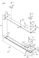
本実施の形態においては、パチンコ機10(外枠11)の下部に配設された演出装置200が特徴的なものとなっている。詳しくは演出装置200の主部を構成するスピーカユニット250について特徴的な構成を有している。以下、図12〜図14を参照して演出装置200及びそれに関連する構成について説明する。図12は外枠11の分解斜視図、図13は演出装置200(詳しくはスピーカユニット250)の構成を示す斜視図、図14はスピーカユニット250の分解斜視図である。
<
In the present embodiment, the
図1に示したように、外枠11の下枠部11aと遊技機主部12の下端部との間には所定の領域が確保されており、当該領域には幕板19が設けられている。つまり、外枠11の下枠部11aと遊技機主部12の下端部との間には幕板領域が設けられている。幕板19は着色された不透明な樹脂により薄板状に形成されており、図示は省略するが、幕板19の前面にはパチンコ機10のメーカ名が記されている。なお、幕板19の前面については、例えばパチンコ機10の機種名を記してもよく、これらメーカ名や機種名を記さなくてもよい。
As shown in FIG. 1, a predetermined area is secured between the
図12に示すように、幕板19の後方には、当該幕板19とともに演出装置200を構成するスピーカユニット250が配設されている。スピーカユニット250は全体として箱状をなしており、その前面部分を覆うようにして幕板19が配置されている。つまり、幕板19には装飾部としての機能が付与されている。
As shown in FIG. 12, a
ここで、外枠11における下枠部11aと左枠部11bとの連結部分には、上記のとおり下側支持用金具18が固定されている。詳細には、下枠部11aと左枠部11bとの連結部分の内側には土台20が設けられており、この土台20上に下側支持用金具18が固定されている。当該構成において、スピーカユニット250は、土台20及び下側支持用金具18に対して前後方向及び上下方向に重ならないようにして、下枠部11a上に設置されている。なお、幕板19は土台20及びスピーカユニット250の両方の前方に位置しており、土台20及びスピーカユニット250の両方にネジ止めされている。
Here, as described above, the lower support metal fitting 18 is fixed to the connecting portion of the
図14に示すように、スピーカユニット250は、音声を出力するスピーカ251と、当該スピーカを収容するケース体252とを備えている。スピーカ251は、円筒状の磁石と、当該磁石の内周に沿って配されたコイルと、コイルの一端側に設けられた振動板と、それら各種構成を格納するホルダ251aと、振動板に一体化されホルダ251aから露出するコーン紙251bとを有する所謂ダイナミックスピーカであり、そのコイルが報知・演出制御装置143に電気的に接続されている。報知・演出制御装置143からスピーカ251(コイル)に電流が供給されることにより、当該スピーカ251から音声が出力されることとなる。
As shown in FIG. 14, the
ケース体252は横長の箱状をなしており、上方に向けて全体が開放されたベース253及び当該ベース253の上面開放部の全体を塞ぐ板状の上蓋254によって構成されている。これらベース253及び上蓋254は、合成樹脂により形成されているが、ベース253及び上蓋254を、ポリカーボネートやアクリル樹脂などといった透明性を有する合成樹脂により形成してもよい。
The
ベース253にはその内側周縁部に複数のボス255が一体形成されているとともに、上蓋254には上記各ボス255に対応させて上下方向に貫通した貫通孔256が設けられている。そして、各ボス255と各貫通孔256とが連通するようにベース253上に上蓋254が載せられ、それら連通されたボス255及び貫通孔256に対して上蓋254の上方からネジ257が螺着されていることにより、ベース253に対して上蓋254が固定されている。つまり、上蓋254はベース253に対して上方から固定されているとともに、その固定は着脱自在な固定具を用いて行われている。この場合、ベース253の上端面の略全体に対して上蓋254の下面が当接している。なお、貫通孔256の上端の周縁部が上蓋254の上面よりも下方に位置するように形成されており、ネジ257の頭部が上蓋254の上面と同じ位置又はそれよりも下方に位置する構成となっている。
A plurality of
ケース体252には、図13に示すように、遊技機主部12の回動先端側に相当する端部に、スピーカ収容領域261が形成されている。このスピーカ収容領域261は、ケース体252における他の領域に比して後方に膨出しており、前後方向寸法が大きくなっている。スピーカ収容領域261を形成する壁部の前後方向寸法は、外枠11の下枠部11aの前後方向寸法と略同一となっている。
As shown in FIG. 13, a
図14に示すように、スピーカ収容領域261にはスピーカ251が収容されている。スピーカ251については、遊技機主部12における前扉枠14のスピーカ部26に設けられたスピーカと略同一形状をなすものの、出力可能な音域(周波数帯)が異なっている。具体的には、スピーカ部26に配置されたスピーカは中・高音域に対応する構成(例えばツイータ)である一方、スピーカ251は低音域に対応するサブウーハとなっている。
As shown in FIG. 14, the
スピーカ251は、スピーカ収容領域261に対して下向きに配置され、図14に示すように、スピーカ収容領域261の側板部268に軸ピン263により回動可能な状態で固定されている。
The
底板部262には、上下方向に貫通し且つスピーカ251(コーン紙252b)の前面よりも若干小さい直径を有する貫通孔264が形成されている。スピーカ251はその前面が貫通孔264の真上に位置し、さらにスピーカ251の前面周縁部の全体が底板部262の上面における貫通孔264の周縁部に密接した状態となっている。上記のようにスピーカ251が設置されていることにより、スピーカ251の前面側から出力された音は、図15の断面図に示すように、貫通孔264を通じてスピーカユニット250の下方に向けて伝搬する。
The
スピーカ251の背面側から出力された音はケース体252内を伝搬し、同じく貫通孔264に向かう構成となっている。つまり、ケース体252にはエンクロージャとしての機能が付与されている。これにより、低音の出力機能の向上を図っている。
The sound output from the back side of the
スピーカ251及び後述するスピーカ用駆動部に動作電力を供給するための電気配線は、スピーカ収容領域261における内側の側板部268からケース体252の外方に延びている。詳細には、ベース253の側板部268には図14に示すようにその上端から下方に凹ませて凹部269が形成されており、凹部269は電気配線の厚み分の大きさを有している。そして、この凹部269に電気配線を通した状態でベース253に対して上蓋254が固定されている。
Electrical wiring for supplying operating power to the
以上説明したスピーカユニット250は、外枠11の下枠部11aに固定されている。詳細には、ケース体252の底板部262がその内側から下枠部11aに対してネジ止めされている。なお、ケース体252の底板部262の外側周縁部にネジ止め用のフランジ部を形成し、当該フランジ部と下枠部11aとをネジ止めする構成としてもよい。この場合、ベース253からの上蓋254の離脱を要することなく、外枠11に対してスピーカユニット250を着脱することができる。
The
スピーカユニット250を下枠部11aに固定した状態では、スピーカユニット250の前縁と下枠部11aの前縁とが同じ位置にあり、スピーカユニット250におけるスピーカ収容領域261の後縁と下枠部11aの後縁とが同じ位置にある。なお、スピーカユニット250の前後方向寸法を幕板19の厚み寸法分小さくし、幕板19が下枠部11aよりもパチンコ機10前方に突出しないようにしてもよい。
In a state where the
ケース体252には、外枠11の右枠部11cに対して前側から当接する延長領域270が形成されている。延長領域270は、スピーカ収容領域261よりも外枠11の右枠部11c側に当該右枠部11cの厚み分延長させて形成されており、さらに前後方向寸法は下枠部11aの右枠部11cよりも前方に延出した分となっている。このように延長領域270を右枠部11cの前面に当接させることで、前後方向の位置決めが行われる。
The
スピーカユニット250が下枠部11aに固定されていることにより、幕板領域から音の出力が行われる。ここで、上記のとおりスピーカ251の前面側から出力された音はスピーカユニット250の下方に向けて伝搬することとなるが、下枠部11aにはこの音をパチンコ機10前方に導くための音導出部271が形成されている(図15参照)。
Since the
音導出部271は、図15に示すように、下枠部11aの上面、底面及び前面にて開放され且つ左右側方及び後方が下枠部11a自身によって閉塞された形状をなしている。この場合、音導出部271における下方に開放された部位(下面開放部)は、遊技ホール(遊技場)のパチンコ機10の設置台Sによって塞がれている。つまり、音導出部271は、パチンコ機10の遊技ホールへの設置状態において下枠部11aの上面及び前面にて開放されている。また、音導出部271の上面開放部272は円形をなしており、その直径はケース体252の貫通孔264の直径と同一となっている。そして、音導出部271の上面開放部272は貫通孔264と上下に重なっている。上記構成であることにより、スピーカ251の前面から出力された音は、貫通孔264→音導出部271を通じてパチンコ機10前方に向けて伝搬する。
As shown in FIG. 15, the
ちなみに、上記のとおりスピーカユニット250は下枠部11aに対して設置する際には、左右方向及び前後方向の両方が位置決めされる。そして、このように位置決め構造が設けられていることにより、スピーカユニット250を下枠部11aに設置した際には自ずと、ケース体252の貫通孔264と音導出部271の上面開放部272とが上下に重なる。よって、スピーカユニット250を設置する上での作業性の向上が図られている。
Incidentally, as described above, when the
ここで、スピーカ251から音が出力されるときには、振動板を境界としてスピーカ251の前面側及び背面側において逆の作用が行われる。具体的には、例えば振動板がスピーカ251の前面側に動くときには、スピーカ251の前面側で空気が押されて「密」となる一方で、背面側は空気の薄い「疎」となり、振動板がスピーカ251の背面側に動くときには、スピーカ251の背面側では空気が押されて「密」となる一方で、前面側は空気の薄い「疎」となる。すなわち、スピーカ251の前面側及び背面側には、逆位相の関係となる音波が出力されることとなる。この場合に、スピーカ251の前面側から出力された音波と、背面側から出力された逆位相の音波とが干渉すると、互いに打ち消しあって遊技者に伝わる音が不鮮明になることが知られている。特に、波長の長い低音域の音に対する影響が顕著で、迫力や臨場感の低下を招く要因となる。
Here, when sound is output from the
これに対して、上記のとおりスピーカ251の前面周縁部は底板部262に対して密接状となっているため、当該底板部262がバッフル板として機能し、スピーカ251の前面側と背面側とは分離されている。よって、スピーカ251の前面側から出力された音波と背面側から出力された音波との干渉が抑制され、スピーカ251からの音の出力が良好に行われるようになっている。
On the other hand, since the front peripheral edge of the
また、低音域の音を増強する上では、スピーカ251から音出口(貫通孔264)までに音が通過する距離を長く確保することが好ましい。これに対して、上記のようにスピーカ251用のケース体252は下枠部11aに沿って左右に延びる横長状をなしており、スピーカ251から音出口までの距離が長く確保され、低音域の音を増強することが可能となっている。
In order to enhance the sound in the low frequency range, it is preferable to ensure a long distance for the sound to pass from the
スピーカユニット250は幕板領域に設けられているため、遊技機主部12を外枠11に対して閉鎖した状態では、スピーカユニット250の上方に遊技機主部12が位置することとなる。この場合、スピーカユニット250は遊技機主部12の重量を受ける。かかる構成について以下に説明する。
Since the
図17等に示すように、ケース体252の上蓋254にはその上面に、複数の金属板(支持板)275が設けられている。具体的には、2枚の金属板275が設けられている。これら金属板275は同一の材料により形成されているとともに同一のサイズ及び形状をしており、上蓋254の前寄りの位置に設けられている。また、一方の金属板275は延長領域270の上部からスピーカ収容領域261の上部に掛けて設けられており、他方の金属板275は音出口寄りの上部に設けられている。
As shown in FIG. 17 and the like, the
金属板275は、上蓋254に対して上方からネジ(支持板用固定具)276が螺着されて固定されている。この場合、図15に示すように、ネジ276の頭部はその上端が金属板275の上面と同じ高さ又はそれよりも下方にあり、ネジ276は金属板275よりも上方に突出していない。金属板275の上面は当該金属板275の厚み分、上蓋254の上面よりも上方にある。
The
図15に示すように遊技機主部12を外枠11に対して閉鎖した状態では、遊技機主部12の下端部が各金属板275上に載る。これにより、遊技機主部12の重量負荷の一部が各金属板275に掛かり、この金属板275に掛かった重量負荷はスピーカユニット250にて受けられる。このように、遊技機主部12の重量負荷の一部をスピーカユニット250にて受けるようにすることで、遊技機主部12が閉鎖状態である場合には、スピーカユニット250のケース体252における上蓋254がベース253に向けて押圧され、これら上蓋254とベース253とが密接する。
As shown in FIG. 15, when the gaming machine
上記のとおりケース体252の内部領域はエンクロージャとしての機能を有する。そして、このエンクロージャとしての機能を効果的に発揮させるためには、ケース体252の密閉性が高いほど好ましい。かかる事情において、上記のように上蓋254とベース253とが密接することでケース体252の密閉性が高められ、当該ケース体252においてエンクロージャとしての機能が効果的に発揮される。これにより、スピーカ251の背面側から出力された音の音質が高められる。
As described above, the internal region of the
因みに、上述の如く外枠11には下側支持用金具18及び土台20が設けられており、これら下側支持用金具18及び土台20においても遊技機主部12の重量負荷が受けられるが、スピーカユニット250は、下側支持用金具18及び土台20に対して前後方向及び上下方向に重なっていない。したがって、下側支持用金具18及び土台20にて受けられた重量負荷はスピーカユニット250に掛からないようになっている。下側支持用金具18は遊技機主部12を回動可能に支持する機能を有しており、遊技機主部12を外枠11に対して開放する際にはその重量負荷の大部分が下側支持用金具18に掛かることとなる。この場合に、上記のように下側支持用金具18及び土台20にて受けられた重量負荷がスピーカユニット250に掛からないようにすることで、遊技機主部12を外枠11に対して開放した際にスピーカユニット250に大きな重量負荷が掛かってしまい当該スピーカユニット250が破損してしまうことが防止される。
Incidentally, as described above, the
また、金属板275はその前側端部に、パチンコ機10前方に向けて下り傾斜した傾斜部277が形成されている。これにより、遊技機主部12を開放状態から閉鎖状態に移動させる場合に、遊技機主部12の下端部は傾斜部277により金属板275上にガイドされ、当該金属板275上に遊技機主部12が載り上げ易くなっている。
Further, the
本実施の形態に示すスピーカユニット250においては、遊技状況(演出の進行状況等)に応じてスピーカ251の向きを変更可能となっていることを特徴の1つとしている。以下、図15を参照してスピーカ251の動作に係る構成について説明する。
One of the features of the
ケース体252には、軸ピン263によって回動可能に軸支されたスピーカ251を当該軸ピン263を中心として前後に回動させることにより、コーン紙521bの向きが変更される構成となっている。このようにスピーカ251の向きを変更するための駆動手段を構成するスピーカ用駆動部301(詳しくはソレノイド)がケース体252に内蔵されている。
The
図示は省略するが、ケース体252には、スピーカ251をコーン紙251bが貫通孔264と対向する位置(以下、第1位置という)に付勢する付勢部材を有している。通常はこの付勢部材による付勢力によってスピーカ251が第1位置に待機した状態となる。
Although not shown, the
スピーカ用駆動部301は電気配線を介して報知・演出制御装置143に接続されている。そして、当該電気配線を通じて報知・演出制御装置143から動作電力が入力されることにより上記付勢部材の付勢力に抗してスピーカ251の向きが下向きから斜め上向きに変更されることとなる。以下、この斜め上向きとなる位置を第2位置という。そして、スピーカ用駆動部301への動作電力の供給が停止した場合には、上記付勢力によってスピーカ251が第1位置に復帰する。
The
なお、ケース体252には、第1位置〜第2位置を越えたスピーカ251の移動を阻止する阻止手段としてのストッパが形成されている。これらストッパによってスピーカ251の位置が第1位置及び第2位置の何れかに規定される。
The
ケース体252(詳しくはベース253)の前面部分については、遊技機前方に凸となるように張り出した張出部265となっており、スピーカ251が上記第2位置に配置された場合にコーン紙251bと対峙する部分(張出部265の上部)には、コーン紙251bの外形に合わせて形成された円形状の貫通孔266が形成されている。上記幕板19は張出部265の外周面に合わせて湾曲しており、その上部には貫通孔266に連通する複数の細孔19aが形成されている。
The front portion of the case body 252 (specifically, the base 253) is an overhanging
より具体的には、図1に示すように細孔19aはハンドル装置41の下方に位置しており、幕板19及び細孔19aにおいて第2位置に配置されたスピーカ251のコーン紙251bとハンドル装置41との間に位置する箇所に細孔19a及び貫通孔266が形成されている。これら貫通孔266及び細孔19aによって演出装置200の内外に繋がる空気の通り道が構成されている。
More specifically, as shown in FIG. 1, the
本実施の形態においては、スピーカユニット250を用いて聴覚的な演出を行う第1演出モードと、聴覚的及び触覚的な演出を行う第2演出モードとが設定されており、遊技状況に応じてこれらのモードが選択される構成となっている。
In the present embodiment, a first effect mode in which an auditory effect is performed using the
ここで、図16を参照して各演出モードにおける演出態様について説明する。図16はスピーカ251の動作態様を示す概略図である。
Here, the production mode in each production mode will be described with reference to FIG. FIG. 16 is a schematic diagram showing an operation mode of the
第1演出モードはスピーカ251からBGMや効果音を出力するモードであり、図16(a)に示すように、スピーカ251が下向きとなる第1位置に待機した状態で音声が出力される。出力された音声は、音導出部271を通じて遊技機前方に出力される。この状態にて音を出力した場合には、音の伝播に伴いコーン紙251bの正面側及び背面側にスピーカ251から遠ざかるようにした空気の流れ(風)が発生することとなる。
The first effect mode is a mode in which BGM and sound effects are output from the
ここで、コーン紙251bの正面側に位置している音導出部271はL字状に折れ曲がっており、音導出部271から流出する空気の流れ(風)の勢いが弱くなるように工夫されている。更に、上述した貫通孔266及び細孔19aについてはコーン紙251bの背面の延長上からずらして配設されており、ケース体252においてコーン紙251bの背面と対峙する部分には貫通孔は存在していない。このため、コーン紙251bの振動によって発生した風が直接ケース体252から流出することが抑制される。
Here, the
一方、第2演出モードとなった場合には、図16(b)に示すように、スピーカ251が斜め上方を向く第2位置に待機した状態で音声が出力される。この場合も、上記第1演出モードと同様に、音声の出力に伴って(コーン紙251bの振動に伴って)空気の流れ(風)が発生する。第2演出モードではスピーカ251のコーン紙251bが貫通孔266と対峙しており、上述した風が貫通孔266→細孔19aを通じてケース体252外に流出する。ここで、当該風はハンドル装置41に向けて吹き付けることとなり、ハンドル装置41を操作している遊技者は、手に風を受けることで触覚的な変化が生じた旨を把握することができる。
On the other hand, when the second effect mode is entered, as shown in FIG. 16B, the sound is output in a state where the
以上詳述した第1の実施の形態によれば以下の優れた効果が期待できる。 According to the first embodiment described in detail above, the following excellent effects can be expected.
振動により音を発生させる(出力する)タイプのスピーカ251が搭載された遊技機においては、音の出力態様によって大小相違するものの少なからず振動部の振動方向に空気の流れ(風)が生じる。ここで、スピーカ251が第1位置に待機している状況下にて音を出力した場合には、振動に伴って発生した風が通風口を通じてハンドル装置41に到達することが規制されるため、スピーカ251からの音によって主として聴覚的な報知・演出機能が発揮される。一方、スピーカ251が第2位置に配置された状況下にて音を出力した場合には、振動に伴って発生した風が貫通孔266及び細孔19aからなる通風口を通じてハンドル装置41に到達することとなる。ハンドル装置41については遊技者が手で操作する部分であるため肌の露出した部分へ風が到達することで、当該風による触覚的な報知・演出機能が発揮される。
In a gaming machine in which a
以上のようにスピーカ251が本来有する音を発生させるという機能と、音の発生に伴い副次的に発揮される機能(空気の流れを生じさせるという機能)とを併用することにより、スピーカという既存の構成を利用し、構造の複雑化や占有領域の拡大を抑えつつ報知・演出機能の向上を実現することが可能となる。
As described above, by combining the function of generating the sound inherent to the
なお、本特徴においては上記スピーカとして重低音タイプのスピーカ(ウーハー等)を適用しており、上記振動が大きなものとなるため振動に伴って発生する風の強さや風量が大きくなりやすい。これにより、上述した作用・効果を顕著に発揮させることができる。 In this feature, a heavy bass type speaker (woofer or the like) is applied as the speaker and the vibration becomes large, so that the strength and the amount of wind generated with the vibration are likely to increase. Thereby, the effect | action and effect mentioned above can be exhibited notably.
また、スピーカ251が第1位置に待機している場合には、振動によって発生した風(空気の流れ)が通風口に向けて吹き付けることが回避される。これにより、第1演出モードにおける上記規制機能(風演出の規制機能)を上手く発揮させることができる。故に、第1演出モードにおける演出機能と第2演出モードにおける演出機能との違いを明確なものとすることができる。
Further, when the
<第2の実施の形態>
上記第1の実施の形態にて説明したように、音出力手段として所謂ダイナミックスピーカを採用している場合、コーン紙が振動することにより当該コーン紙の正面側と背面側の両方に空気の流れが生じる。ここで、当該第1の実施の形態においては、第1演出モード時にはコーン紙251bが下方を向きその背面側に上記通風口(細孔19a等)が位置しないように各構成の配置を工夫した。ここで、ケース体252を用いて低音の出力機能の強化を図っている場合には、その内部にて空気の流れが生じ、ケース内にて圧縮された空気は、ケースに形成された孔等を通じてケース外に流出しようとする現象を完全に無効化できるものではない。言い換えれば、スピーカ251から音を出力しようとすれば、第1演出モード/第2演出モードの如何に関わらず、少なくとも通風口からの空気漏れは発生する。つまり、第1演出モード(主としてBGMや効果音等の音声を出力するモード)であっても、通風口からの空気の漏れを規制することは困難である。これでは、第1の実施の形態に示した第1演出モードと第2演出モードとの差異を遊技者が体感しづらくなると懸念される。
<Second Embodiment>
As described in the first embodiment, when a so-called dynamic speaker is employed as the sound output means, the flow of air on both the front side and the back side of the cone paper is caused by the vibration of the cone paper. Occurs. Here, in the first embodiment, the arrangement of each component is devised so that the
また、第1演出モードにおいてケース体252をエンクロージャとして機能させる上で、通風口の存在が同機能を好適に発揮させる上での障害になり得る。
In addition, when the
本実施の形態においては、このような各種不都合を解消して、両演出モードの違いを明確にしたりエンクロージャとしての機能を向上させたりする工夫が施されている。以下、図17を参照して、当該工夫に係る構成について説明する。 In the present embodiment, such various inconveniences are solved, and a device for clarifying the difference between the two production modes or improving the function as an enclosure is provided. Hereinafter, with reference to FIG. 17, the structure which concerns on the said device is demonstrated.
図17(a)に示すように、スピーカ251A用のホルダ251aAにはスピーカの回動中心から放射方向に延びるアーム部251cAが形成されている。アーム部251cAの先端には、上記通風口(詳しくは貫通孔266)をケース体252の内側から塞ぐ曲板状のカバー部251dAが形成されている。このため、第1演出モードとなっている場合には、貫通孔266→細孔19aを通じてケース体252から空気が漏れ出すことが回避される。
As shown in FIG. 17A, the holder 251aA for the
また、当該第1演出モードについては、既に説明したように主としてBGMや効果音等の音声を出力するモードであるが、ケース体のエンクロージャとしての機能が強化され、音声の出力機能、特に低音域での音の出力機能が向上することとなる。 The first effect mode is a mode for mainly outputting sounds such as BGM and sound effects as already described. However, the function of the case body as an enclosure is enhanced, and the sound output function, particularly the low frequency range. This will improve the sound output function.
ここで、カバー部251dAは、コーン紙251bAの背面からずれた位置、詳しくはスピーカ251の回転中心(軸ピン263)を基準としてコーン紙251bからおよそ90度傾いた位置に配置されており、更には、上記回転中心を中心とする弧状をなしている。このため、コーン紙251bの背面側に発生する空気の流れがカバー部251dAに直接当たることが抑制され、仮に、カバー部251dAに当たったとしてもその風がスピーカ251Aの正面側に向けて跳ね返ることが抑制されている。
Here, the cover portion 251dA is disposed at a position shifted from the back surface of the cone paper 251bA, more specifically, at a position inclined about 90 degrees from the
なお、図17(b)に示すように、第2演出モードへの切り替えがなされた場合、カバー部251dAとケース体252の底板部262との間には隙間が確保される。これにより、コーン紙251bの背面側に発生する空気の流れがカバー部251dAによって妨げられにくくなっている。更には、カバー部251dAがケース体252内での空気の動きに一定の流れを付与する整流板として機能することにより、ケース体252内で上記通風口を通じた空気の流出を妨げるような乱れが生じることを抑制できる。これにより、コーン紙251bと張出部265との間に隙間が生じる構成においても、スピーカ251A→貫通孔266→細孔19aの空気の流れが上記乱れによって妨げられるといった不都合を生じにくくすることができる。
As shown in FIG. 17B, when switching to the second effect mode, a gap is secured between the cover portion 251dA and the
<第3の実施の形態>
上記各実施の形態に示すスピーカの振動部(コーン紙251b等)を利用した風の出力について音の出力に依存しており、風の出力を継続するには音を継続的に出力する必要がある。また、風の出力を強くしようとすれば、音量が大きくなって触覚的な演出機能よりも聴覚的な演出機能が際立ってしまう可能性がある。つまり、通常のスピーカの出力態様では、触覚的な報知・演出機能が聴覚的な報知・演出機能に強く依存してしまう。
<Third Embodiment>
The wind output using the vibration part (
この点、本実施の形態においては、上記第2演出モードの演出態様に上記不都合を回避する工夫が施されている。具体的には、第2演出モード(特定箇所に風を届ける状態)においては、非可聴領域に属する音を出力する構成とすることで、出力を上げて風量を増大させた場合であっても音自体は聞こえないので上記触覚的な報知・演出機能を聴覚的な制約を受けずに任意に設定でき、当該機能を上手く発揮させることが可能となっている。以下、図18を参照して、本実施の形態における第2演出モード実行時の音声出力制御の流れについて説明する。 In this regard, in the present embodiment, a device for avoiding the inconvenience is applied to the effect mode of the second effect mode. Specifically, in the second performance mode (the state in which the wind is delivered to a specific location), even if the output is increased and the air volume is increased by outputting sound belonging to the non-audible area. Since the sound itself cannot be heard, the tactile notification / production function can be arbitrarily set without any auditory restrictions, and the function can be performed well. Hereinafter, with reference to FIG. 18, the flow of audio output control when executing the second effect mode in the present embodiment will be described.
図18(a)に示すように、t0のタイミングにて第2演出モードに係る遊技回が開始されると、全てのスピーカからBGMの出力が開始される。この際、遊技機下部に配置されたスピーカ251については、その音量が他のスピーカよりも小さく、すなわち音声演出に係る寄与度が低く設定されている。
As shown in FIG. 18 (a), when the game turn in the second effect mode is started at the timing t0, the output of BGM is started from all the speakers. At this time, the volume of the
なお、本実施の形態については、下部のスピーカ251からの音の出力を行う構成としたが、下部のスピーカ251については、通常は使用しない構成(例えば効果音の出力時のみ出力される構成)としてもよい。遊技ホールでは様々な音が入り混じっており、小さな音が突然消えたとしても遊技者がそれに気付く可能性は低い。しかしながら、下部のスピーカからの音の出力の停止=風演出実行となれば、遊技者によっては風演出の有無を聴覚的な情報から判断できる可能性が高くなる。この点、本変形例のように、下部のスピーカ251を効果音用として用いる構成とすれば、そのような不都合を好適に回避できる。
Although the present embodiment is configured to output sound from the
報知・演出制御装置143にて風演出を実行するタイミング(t1のタイミング)になったと判定した場合には、スピーカ251に係る演出態様が音に関するものから風に関するものに切り替る。具体的には、スピーカ251の向きを変更して、貫通孔266及び細孔19aを通じた風の出力が可能な状態に切り替る。これに併せて、スピーカ251から出力される音の周波数が可聴領域に属するものから非可聴領域に属するものに変更される。
When it is determined by the notification /
本実施の形態に示す「可聴領域」は人を基準に設定されており、図18(b)に示すように、およそ20Hz〜20kHzの周波数帯を示すものである。「非可聴領域」については、極低音側と極高音側とに大別されるが、下部のスピーカ251はサブウーハであり、低音用のスピーカとなっている。そこで、具体的には、20Hzよりも大きい低音(可聴音)から20Hzよりも小さい低音(非可聴音)へと閾値20Hzを跨ぐようにして変更される。
The “audible area” shown in the present embodiment is set based on a person, and indicates a frequency band of approximately 20 Hz to 20 kHz as shown in FIG. The “non-audible region” is roughly classified into an extremely low sound side and an extremely high sound side, but the
この切り替えにより、以降はスピーカ251からの音が実質的に聞こえなくなる。これに併せて、又は僅かに送れて出力される音量が大きくなるように音量も変更されることとなる。これにより発生する風の風量や風圧を上げることが可能となる。この場合であっても、音自体は非可聴領域に属しているため、遊技者に騒々しいとの印象を与えることを回避することができる。
As a result of this switching, the sound from the
スピーカを用いて風を発生させる上では、コーン紙251bの振幅が大きいほうが有利となる。このため、低音用のスピーカ251を用いて風演出を実行することには技術的意義がある。
In order to generate wind using a speaker, it is advantageous that the
因みに、本実施の形態においては、20Hz以下の極低音を利用して風演出を行う構成としたが、ツイータ等の高音用のスピーカにより20kHz以上の極高音を利用して風演出を行ってもよい。但し、上述したように風演出を実行するには、ある程度のコーンの振幅を担保する必要があるところ、高音では振幅の確保が困難になりやすい。以上の理由から、スピーカを利用して風演出を行う場合には、本実施の形態に示したように低音用のスピーカ及び低音側の非可聴領域に属する音を利用することが好ましい。 By the way, in this embodiment, the wind effect is made using the extremely low sound of 20 Hz or less. However, even if the wind effect is made using the extremely high sound of 20 kHz or more by a high sound speaker such as a tweeter. Good. However, as described above, in order to execute the wind effect, it is necessary to ensure a certain degree of cone amplitude. For the above reasons, when a wind effect is performed using a speaker, it is preferable to use a low-frequency speaker and a sound belonging to a non-audible area on the low-frequency side as shown in the present embodiment.
<第4の実施の形態>
上記各実施の形態に示した演出装置200については、演出装置200を構成するスピーカ251により触覚的な変化を伴う演出を実行する構成としたが、本実施の形態における演出装置400については上記各実施の形態と同様にスピーカを用いた演出を行うもののその演出態様が異なっている。以下、図19及び図20を参照して演出装置400について説明し、その後、当該演出装置400による演出の概要について例示する。図19は演出装置400及びその周辺構成を正面から見たパチンコ機10Bの部分拡大図、図20は図19のA−A線部分断面図である。なお、パチンコ機の基本構造については、上記第1の実施の形態と同様であるため、これら共通する構成については説明を援用する。
<Fourth embodiment>
About the production |
図19に示すように、本実施の形態における演出装置400は前扉枠14の上枠部に配置されている。演出装置400は上枠部(窓部21の上端縁)に沿って左右に延びる横長状の表示部401を有している。表示部401は前扉枠14の前面カバー体の一部を構成しており、その前面は照射された光の一部を透過し残りの一部を反射するハーフミラー(ビームスプリッタ)となっている。
As shown in FIG. 19, the
図20に示すように表示部401の背後には、左右に複数の発光体441(詳しくはLED)が実装された発光基板440が設けられている。発光基板440は、発光体441の搭載面が遊技機正面側を向くようにして、すなわち表示部401の背面と対向するようにして上記前面カバー体に固定されている。発光基板440は報知・演出制御装置143に電気的に接続されており、この報知・演出制御装置143からの信号に基づいて点灯/点滅する構成となっている。
As shown in FIG. 20, a
発光体441からの光が上記表示部401を通過して遊技機前方に照射されることにより、表示部401が光る構成となっている。なお、上述したように表示部401はハーフミラーであるため、表示部401を通じて発光基板440や発光体441を目視で確認することは困難又は不可となっている。
The light emitted from the
本実施の形態においては、表示部401と発光基板440との間に表示部401の長手方向に移動可能な可動式の装飾体410が配設されている。装飾体410は左右に延びるスライドレール411によって左右にスライド移動可能な状態で支持されており、当該スライドレールには装飾体410を当該スライドレール411に沿ってスライド移動させる駆動源としてのモータ412が取り付けられている。モータ412についても上記発光基板440と同様に報知・演出制御装置143に電気的に接続されており、当該報知・演出制御装置からの駆動信号が入力されることにより、装飾体410を移動させる。
In the present embodiment, a movable
なお、本実施の形態には、駆動力の伝達手段としてスライドレール411に沿って配置された環状のベルト部材(図示略)を使用しているが、装飾体410への駆動力の伝達方式については任意である。
In this embodiment, an annular belt member (not shown) disposed along the
ここで、図20に基づいて発光基板440(詳しくは発光体441)からの光の照射領域と、表示部401との位置関係について説明する。
Here, a positional relationship between the
既に説明したように表示部401の前面については、ハーフミラーとなっているが、その背面には、一部ミラー加工が施されている部分が存在する。具体的には、表示部401の左右両端部には前後に延びる仕切り板部が形成され、これら仕切り板部によって上記装飾体410の格納領域が区画形成されている。
As described above, the front surface of the
表示部401の背面においては、この区画領域を構成している部分(格納領域形成部403)がミラー加工の対象となっており、発光体441からの光が遊技機前方へ照射されることを抑制している。つまり、表示部401は、前面がハーフミラーとなっている部分(表示領域形成部402)と、当該表示領域形成部402の左右両側に設けられた前面がハーフミラー/背面がミラーである格納領域形成部403とで構成されている。
On the back surface of the
本実施の形態においては、装飾体410は魚の形を模して形成されており(図19参照)、発光体441が発光している場合に装飾体410が表示領域形成部402と対峙する位置を通過することにより、遊技者は表示部401を魚影が通過したと認識できる構成となっている。
In the present embodiment, the
図19に示すように、前扉枠14において表示部401の左右両側となる部位には、スピーカ430がそれぞれ配置されている。スピーカ430は、報知・演出制御装置143に電気的に接続されており、遊技状況に応じてBGMや効果音を出力する構成となっている。
As shown in FIG. 19,
前扉枠14の前面カバー体には、スピーカ430からの音をパチンコ機10前方に導くための音導出部405が形成されている。音導出部405はスピーカ430のコーン紙の外形に合わせて形成された筒状をなしており、その底部には前後に貫通する貫通孔406が形成されている。なお、上述した仕切り部については光を透過しない構成となっており(詳しくはミラー加工されており)上記発光基板440からの光が上述した音導出部405やスピーカ430に届かないように規制されている。
The front cover body of the
本実施の形態におけるスピーカ430についても上記各実施の形態と同様に可動式となっている。具体的には、発光基板440の背面側には、左右に延びるレール部材431が配設されており、このレール部材431によってスピーカ430が上記装飾体410の移動方向と同じ方向に移動可能となるように支持されている。レール部材431には、装飾体410を当該スライドレール411に沿ってスライド移動させる駆動源としてのモータ432が取り付けられている。モータ432についても上記発光基板440や装飾体410用のモータ412と同様に報知・演出制御装置143に電気的に接続されており、当該報知・演出制御装置からの駆動信号に基づいてスピーカ430の位置を左右に変更可能となっている。なお、以下の説明では音導出部405を通じて音声の出力を行うスピーカ430の位置を初期位置と称する。また、左右のスピーカ430の両方が移動可能となっているが、以下の説明においては、右側のスピーカ430の動きについて例示する。
The
因みに、スピーカ430は上記装飾体410の高さ位置と同じ高さ位置となるように配置されており、両レール411,431を平行とすることにより、装飾体上下方向での高さ関係が維持される構成となっている。
Incidentally, the
演出装置400によるスピーカ430及び装飾体410の連動演出には大別して、3つの演出パターンが設定されている。具体的には、
(1)完全同期演出
(2)遅れ演出
(3)逆向き演出
である。
There are roughly three production patterns for the linked production of the
(1) Fully synchronized production (2) Delayed production (3) Reverse production.
以下、図21を参照して(1)の完全同期演出について説明する。図21は完全同期演出実行時の演出装置400の動作態様を示す概略図であり、図21(a)→図21(b)→図21(c)→図21(d)→図21(e)→図21(f)の順に演出が進行する。
Hereinafter, the complete synchronous effect (1) will be described with reference to FIG. FIG. 21 is a schematic diagram showing an operation mode of the
完全同期演出が実行される場合には、先ず発光体441が点灯した状態となる。その後、右側のスピーカ430が装飾体410と前後に重なる位置に移動し、図21(b)に示すように装飾体410とスピーカ430とがその位置関係を維持しながら右側から左側へと移動する。なお、既に説明したように装飾体410は魚を模しており、当該魚が左側を向くようにして配置されている。つまり、装飾体410の移動方向は魚の遊泳方向と同じになるように設定されている。
When the complete synchronization effect is executed, the
装飾体410が格納領域を脱して発光体441の前方に移ることにより、同発光体441からの光が装飾体410によって遮られることとなる。これにより、表示部401に魚影が映し出されることとなる。ここで、スピーカ430からは魚が泳ぐ際に発生するような擬似効果音を継続的に出力することにより、視覚に係る演出と聴覚に係る演出が連動することとなり、両者の関係性が強くなる。
When the
ここで、発光基板440及び表示部401(詳しくは表示領域形成部402)には、細孔404,442が形成されており、移動中のスピーカ430からの音が遊技機正面側へ抜けるよう工夫されている。特に細孔404については、当該細孔404を通じて発光基板440が視認困難又は不可となるように小さく設定されており、発光基板440や装飾体410を直接目視にて確認することが難しくなるように工夫されている。
Here, pores 404 and 442 are formed in the
図21(b)→図21(c)に示すように、スピーカ430から効果音の出力が継続された状態で遊技機の中心(遊技者の顔があると想定されるライン)を横切ることにより、ドップラー効果によって音色が変化することとなる。
As shown in FIG. 21 (b) → FIG. 21 (c), by crossing the center of the gaming machine (a line assumed to have a player's face) with the output of sound effects from the
但し、遊技機は遊技者の顔が遊技機の左右方向における中央位置にある状態で、遊技を行いやすくなるように設定されてはいるが、遊技者の体格や姿勢によっては同遊技者の顔の位置が上記中心線CLから外れる可能性もある。この場合であっても、実際にスピーカ430と装飾体410との動きが連動しているため、上記音色の変化を生じさせる上で、遊技者の顔の位置のばらつきを許容することが可能となっている。
However, the gaming machine is set so that it is easier to play with the player's face in the center in the left-right direction of the gaming machine, but depending on the player's physique and posture, the player's face May deviate from the center line CL. Even in this case, since the movements of the
図21(d)→図21(e)に示すように、装飾体410が左側の格納領域形成部403に到達した後は、先ずスピーカ430が初期位置へと復帰する。この際、スピーカ430からの効果音等の音声の出力は一時的に中断され、初期位置に復帰後右側のスピーカ430と同様に効果音やBGM等の出力が再開されるように報知・演出制御装置143によって制御される。
As shown in FIG. 21 (d) → FIG. 21 (e), after the
スピーカ430が初期位置に復帰した後のタイミングであって、遊技回の終了するタイミングにて発光体441が一時的に消灯された状態となり、その間に図21(e)→図21(f)に示すように装飾体410が元の位置(右側の格納領域形成部403)に復帰する。この際、発光体441の発光が回避されているため、装飾体410の影が表示部401に映ることが回避される。
At the timing after the
都度の遊技回に対応して選択される演出は、特別遊技状態へ以降する可能性と関連性が付与されている。ここで、上記(2)の遅れ演出については(1)の完全同期演出よりも特別遊技状態へ移行する期待度が高くなるように設定されている。 The rendition selected in response to each game round is given the possibility and relevance to the special gaming state. Here, the delay effect of (2) is set such that the degree of expectation for shifting to the special game state is higher than that of the complete synchronous effect of (1).
遅れ演出が実行される場合には、概要は図21を参照して説明した完全同期演出と同様であるが、スピーカ430及び装飾体410が、前後に重なった状態を維持しながらスライド移動するのではなく、少し左右にずれた状態を維持しながらスライド移動することとなる。より詳しくは、進行方向に対してスピーカ430の動きが若干遅れるようにスピーカ430用のモータ432(図20参照)に対する遅延処理がなされる。このように、スピーカ430と装飾体410との位置関係にズレを生じさせることで、ドップラー効果による音色の変化が視覚的な変化からずれて発生することとなる。これにより、演出の多様化が実現される。
When the delayed effect is executed, the outline is the same as the completely synchronized effect described with reference to FIG. 21, but the
また、既に説明したように本実施の形態における装飾体410は魚を模して形成されており、その進行方向が自然な向きと不自然な向きとが存在する。ここで、(3)の逆向き演出においては、遊技回終了時の消灯期間中に装飾体410を予め右側の格納領域形成部403から左側の格納領域形成部403に移動させるとともに、左側のスピーカ430を当該装飾体410の背後に配置しておき、演出装置400により逆向き演出を実行する場合に同スピーカ430から魚が泳ぐ際に発生するような擬似効果音を継続的に出力しつつ装飾体410を右側の格納領域形成部403へ移動させる。これにより、通常の魚の動きとは逆向きの動きが実現され、演出の更なる多様化が実現される。
Further, as already described, the
以上詳述した本実施の形態によれば、以下の優れた効果をそうする。 According to the embodiment described above in detail, the following excellent effects are achieved.
装飾体410の動きに連動するようにしてスピーカ430の位置を変更することが可能となる。この構成によれば、音の出力箇所を演出対象の位置に合わせて変えることが可能となり、視覚及び聴覚の両方を対象とする演出を行う場合に、演出対象と同演出対象に対応する音との関連性を強くすることが可能となる。これにより演出の一体感を高め、当該演出への遊技者の注目度向上に貢献できる。
The position of the
例えば、本実施の形態に示す演出機能と同等の機能を発揮させること等を目的として複数のスピーカを採用し、各スピーカの出力等に差を生じさせることにより、あたかも音の出力箇所が移動しているかのように錯覚させることも可能である。しかしながら、このような構成では、必要となるスピーカの数が多くなり、さらにスピーカの出力制御(音制御)に係る負荷も大きくなる。この点、スピーカ自体を可動式とし、演出対象に連動させて移動させる構成とすれば、それらの各種不都合の発生を好適に回避することができる。 For example, by adopting multiple speakers for the purpose of demonstrating the same function as the presentation function shown in this embodiment and making a difference in the output of each speaker, the output location of the sound moves. It is also possible to make an illusion as if it were. However, with such a configuration, the number of required speakers increases, and the load related to speaker output control (sound control) also increases. In this regard, if the loudspeaker itself is movable and moved in conjunction with the production target, it is possible to suitably avoid the occurrence of various inconveniences.
可動式のスピーカ430によって音の出力箇所を装飾体410の位置に応じて変化させることにより演出効果の向上を図る場合、視覚的に注目すべき箇所はあくまで装飾体410である。ここで、仮にスピーカ430自体の動きを遊技者が容易に視認できる構成となってしまっては、遊技者の視線がスピーカ430に向いてしまい演出対象に付与された視覚的な演出効果が上手く機能しなくなる。この点、表示部401や発光基板440等によってスピーカ430をその移動範囲にて覆う構成とすればそのような不都合の発生を好適に回避することができる。
In the case of improving the effect by changing the sound output location according to the position of the
音の出力を継続しながらスピーカ430が装飾体410に追従して移動することにより、音の出所があたかも演出対象であるかのように表現することが可能となる。音の出所を装飾体とする場合には、当該装飾体にスピーカを搭載すればよい。ここで、装飾体の動作速度は装飾体の重さに依存しやすい。このため、例えば装飾体にスピーカを搭載することが装飾体の重量が嵩んで軽快な動きを妨げる要因になり得る。この点、上述の如く装飾体410とは別に可動式のスピーカ430を設けることにより、装飾体410の軽快な動き担保しつつ、上記音と動きの連携を担保することが可能となる。
As the
なお、本実施の形態に示す装飾体410についてはその形状に合わせて自然な進行方向が特定される構成としたが、これに限定されるものではない。装飾体410の形状については上記方向性が生じないものととすることも可能である。また、本実施の形態に示すような方向性を有する装飾体410については、当該装飾体410を回転させることでその向きを変更するモータ等のアクチュエータを採用してもよい。
Note that the
また、装飾体410を移動範囲内の任意の位置にて停止させる構成とすることも可能である。例えば、装飾体410が左側の格納領域形成部403に近づけば近づくほど特別遊技状態への移行期待度が高くなるような演出を実行する構成とすることも可能である。この場合、移動方向に多数のスピーカを並設して出力対象となるスピーカを切り替える構成とすることにより、装飾体410の動きに連動しているかのような音声の出力が可能であるが、装飾体410の移動位置とスピーカの数及び配置との関係から演出に制約が生じやすくなる。この点、本実施の形態に示す構成によれば、装飾体410の停止位置等の多様化を容易に実現できる。
In addition, the
<第5の実施の形態>
上記第4の実施の形態に示した演出装置400ではスピーカ430と装飾体410とを連動させる構成としたが、可動式のスピーカの連動対象は実態を伴うものである必要はなく演出対象として視認可能となるものであればよい。そこで、本実施の形態の演出装置500においてはスピーカと連動する対象のより複雑な動きを許容するべく、上記第4の実施の形態とは演出装置の構成が異なるものとなっている。そこで以下、図22を参照して本実施の形態における演出装置500及びそれに関連する構成について説明する。なお、パチンコ機の基本構造については、上記第1の実施の形態と同様であるため、これら共通する構成については説明を援用し、第4の実施の形態との相違点を中心に説明を行う。
<Fifth embodiment>
In the
上記各実施の形態においては図柄表示装置を液晶表示装置にて構成したが、本実施の形態においては、演出機能を上手く発揮させる上で薄型の図柄表示装置510を採用している。具体的には、有機ELによって図柄表示装置510を構成している。上記第4の実施の形態については、装飾体410をスピーカの連動対象としたが、本実施の形態においては図柄表示装置510の表示画面510aに映し出される女の子を模したキャラクタ画像が連動対象となっている点で上記第4の実施の形態と相違している。
In each of the embodiments described above, the symbol display device is configured by a liquid crystal display device. However, in the present embodiment, a thin
図22に示すように、図柄表示装置510の背面側には、当該図柄表示装置510とともに演出装置500を構成する音声出力装置520が同図柄表示装置510に重なるようにして配置されている。
As shown in FIG. 22, on the back side of the
音声出力装置520は、報知・演出制御装置143から出力される信号に基づいて音声を出力するスピーカ530と、スピーカ530を左右方向に移動可能に保持する横レール531と、横レール531を昇降可能に保持する左右一対の縦レール535とを備えている。また、音声出力装置520には、報知・演出制御装置143に接続され当該報知・演出制御装置143から駆動信号が入力されることによりスピーカ530を左右方向に移動させる駆動源としての第1モータ533と、同じく報知・演出制御装置143に接続され当該報知・演出制御装置143から駆動信号が入力されることにより横レール531を昇降させる駆動源としての第2モータ536とが設けられており、報知・演出制御装置143によってスピーカ530の位置を所定の範囲内にて上下左右の任意の位置に図柄表示装置510の背面に沿って変更することが可能となっている。
The
ここで、スピーカ530の移動範囲については、図柄表示装置510における上記キャラクタ画像(詳しくはキャラクタ画像の口部分(以下、特定箇所TPという))の表示領域MEに合わせて設定されており、表示領域ME内にてキャラクタ画像(特定箇所TP)が移動する場合には、その移動に追従してスピーカ530の位置が変更される。
Here, the movement range of the
図柄表示装置510の表示領域MEには前後に貫通する複数の細孔511が形成されている。スピーカ530から音声が出力された場合には、それら細孔511を通じて遊技機前方へ音声が届けられることとなる。
A plurality of
ここで、演出装置500を用いた連動演出について、図23の概略図を参照して例示する。なお、図23においては説明の便宜上、細孔511やレール531,535等の一部の構成を省略して示している。
Here, an interlocking effect using the
図23にて例示する連動演出については、図23(a)→図23(b)→図23(c)→図23(d)→図23(e)→図23(f)の順に進行する。具体的には、遊技回が開始した場合には、先ずそれまで停止表示されていた各図柄列が左右にスクロール表示される(図23(a)参照)。 The interlocking effects illustrated in FIG. 23 proceed in the order of FIG. 23 (a) → FIG. 23 (b) → FIG. 23 (c) → FIG. 23 (d) → FIG. 23 (e) → FIG. . Specifically, when the game turn is started, each symbol row that has been stopped and displayed until then is scrolled to the left and right (see FIG. 23A).
その後、上図柄列→下図柄列の順にスクロール表示が終了し、図23(b)に示すように有効ライン上に特別遊技状態への移行に対応し得る図柄組み合わせが停止表示され(所謂リーチ表示に移行し)、リーチ表示移行後に所定期間を経過するとスーパーリーチ移行するか否かの分岐が発生することとなる。図23の例においてはスーパーリーチへの移行が確定しており、当該スーパーリーチに係る演出として表示画面510aに上記キャラクタ画像が表示されることとなる。なお、スーパーリーチ移行時には、それまで表示画面510aの全域に表示されていた図柄が表示画面510aの隅部に縮小表示され、キャラクタ画像の視認性が担保される。
After that, the scroll display is finished in the order of the upper symbol row → the lower symbol row, and as shown in FIG. 23B, the symbol combinations that can correspond to the transition to the special game state are stopped and displayed on the active line (so-called reach display). When a predetermined period elapses after shifting to reach display, a branch for determining whether or not to shift to super reach occurs. In the example of FIG. 23, the transition to super reach is confirmed, and the character image is displayed on the
図柄表示装置510にて実行される表示演出の概要については、報知・演出制御装置143にて決定され、その内容についても報知・演出制御装置143にて把握されている。上記キャラクタ画像が表示される際には、報知・演出制御装置143は、当該キャラクタ画像(詳しくは特定箇所TP)の背後に位置するようにスピーカ530を移動させる処理を実行する。これにより、図23(c)に示すように、特定箇所TPの背後にスピーカ530が位置することとなる。
The outline of the display effect executed by the
本実施の形態においては、スーパーリーチへの移行後に表示されたキャラク画像が予め設定された台詞をしゃべりながら表示画面510aを左右に移動する。このような演出を実現すべく、スピーカ530からは上記台詞が出力されながら、当該スピーカ530の位置がキャラク画像(特定箇所TP)に追従して移動する(図23(c)→図23(d)→図23(e)参照)。
In the present embodiment, the character image displayed after the transition to super reach moves the
図23(e)に示すように表示画面510aの中央にキャラクタが移動してその姿勢が変化するのに合わせて(ガッツポーズをとるのに合わせて)、スピーカ530から当該遊技回の遊技結果に対応する台詞(例えば「スーパーラッキー」)が出力され、その後、縮小表示されていた図柄が当該遊技回の遊技結果に対応する図柄組み合わせを形成した状態で表示画面510aに拡大表示される。
As shown in FIG. 23 (e), as the character moves to the center of the
表示画面510aに表示されるキャラクタ画像の位置に合わせてスピーカ530が移動することにより、画像と音との関係性を強くすることができる。ここで図柄表示装置510の背後にスピーカ530を配置した場合、図柄表示装置510自体が遊技機前方への音の伝わりを妨げる要因となり得る。この点、表示画面510aにおいてスピーカ530の移動範囲と重なる範囲(表示領域ME)に複数の細孔511を散在させることにより、そのような不都合が生じにくくなっている。
By moving the
なお、本実施の形態に示す図柄表示装置の前方にはガラスパネル22が存在しており、更には遊技領域に囲まれた領域を通過するようにしてスピーカ530からの音が出力されることとなる。このため、上記各実施の形態に示したように前扉枠14や外枠11にスピーカを配した場合と比較して、遊技者に音が伝わりにくくなると想定される。そこで、本実施の形態に示す構成を採用する場合には、指向性の強いスピーカを採用したり、ガラスパネル22の遮音機能を遊技球の打音に対応する音域で高くするとともに、スピーカ530から出力される音を遮音機能が強く作用する音域を外すように設定したりすることが好ましい。
Note that there is a
<第6の実施の形態>
上記各実施の形態においては可動式のスピーカを用いて様々な演出を行う構成としたが、本実施の形態ではスピーカが有する磁石の磁力を用いて他の構成を動作させる構成が採用されている点でそれら各実施の形態と構成が相違している。具体的には、スピーカの磁力を利用することにより、報知/演出の各機能を好適に発揮させることが可能となっている。以下、図24及び図25を参照して本実施の形態における報知・演出装置600を、上記機能を発揮させる上で主要な構成を中心に説明する。図24(a)は第6の実施の形態における報知・演出装置及びその周辺構成を正面から見たパチンコ機10Cの部分拡大図、図24(b)は表示板を示す概略図で、図25は図24(a)のB−B線部分断面図である。
<Sixth Embodiment>
In each of the above embodiments, a configuration is used in which various presentations are performed using a movable speaker. However, in this embodiment, a configuration in which another configuration is operated using the magnetic force of a magnet included in the speaker is employed. In this respect, the configuration is different from those of the respective embodiments. Specifically, by using the magnetic force of the speaker, it is possible to suitably exhibit the notification / production functions. Hereinafter, with reference to FIG. 24 and FIG. 25, the notification /
図24(a)に示すように、パチンコ機10の前扉枠14の上隅部には左右対象となるようにして上記報知・演出装置600がそれぞれ配設されている。左右の報知・演出装置600については同様の構成を有しているため、以下の説明では右側の報知・演出装置600について説明し、左側の報知・演出装置600についての説明は省略する。
As shown in FIG. 24A, the notification /
報知・演出制御装置143は、遊技機の右側縁部寄りに配置されたスピーカ610を有している。スピーカ610は、前扉枠14を構成するベース体660と、同ベース体660に固定された前面カバー体650によって挟まれた空間に収容されている。
The notification /
より詳しくは、図25に示すように、前面カバー体650は遊技機正面側を向いている正面部と遊技機側方を向いている側面部とを有しており、それら両者を繋ぐ曲面状のコーナ部とによって構成されている。
More specifically, as shown in FIG. 25, the
上記正面部には、ベース体660側に突出するようにして仕切り部651が形成されており、この仕切り部651によって前面カバー体650とベース体660とによって挟まれた空間にスピーカ610を収容する収容部652が区画形成されている。この収容部652はスピーカ610用のエンクロージャとして機能する。
A
スピーカ610は上下に延びる軸ピン615によって回動可能に軸支されており、コーン紙610aが遊技機正面側を向く第1状態と、コーン紙610aが遊技機側方を向く第2状態とに切替可能となっている。スピーカ610には当該スピーカ610を回動させる際の駆動源としてのモータ616が接続されており、報知・演出制御装置143からモータ616に駆動信号が出力されることで、スピーカ610の向きが変化する構成となっている。より詳しくは、スピーカ610の回動範囲は図示せぬストッパによっておよそ90度に限定されており、報知・演出制御装置143から第1駆動信号が入力されることによりスピーカ610を反時計回りに回動させ、第2駆動信号が入力されることにより同スピーカ610を時計回りに回動させる構成となっている。
The
本実施の形態に示すスピーカ610は、その出力態様が報知・演出制御装置143により制御されている。具体的には、演出実行時にはBGMや効果音等の音声が出力され、パチンコ機10Cに異常が発生した場合には警告音等の音声が出力される構成となっている。なお、異常の発生については主制御装置162によって監視されており、例えば球詰まりの発生や本来発生するはずのない入賞や特典の付与等が発生した場合には同主制御装置162にて異常が発生したと判定し、その旨を示す異常検出コマンドが報知・演出制御装置143に出力される。
The output mode of the
スピーカ610によって演出を行う場合には音声を遊技者に届けることが効果的であり、異常報知を行う場合には音声を他の遊技者やホール管理者に届けることが効果的となる。このような事情に鑑みて、本実施の形態には上記異常報知を行う場合に、スピーカ610を回動させてその向きを正面から側方に変更する。
It is effective to deliver a sound to the player when performing an effect by the
前面カバー体650の正面部にはスピーカ610が第1状態となっている場合にコーン紙610aと対峙する部位に第1貫通孔655が形成されており、側面部及びコーナ部にはスピーカ610が第2状態となっている場合にコーン紙610aと対峙する部位に第2貫通孔656がそれぞれ形成されている。第1状態では効果音やBGM等が主として第1貫通孔655を通じて遊技機前方に出力され、第2状態では警告音が主として第2貫通孔656を通じて遊技機側方に出力されることとなる。
When the
ここで、スピーカ610のホルダ610bには上記第1の実施の形態に示したように円筒状の磁石が内蔵されている。スピーカ610の向きが変わると、磁束の向きも変化し磁界の影響が及ぶ範囲も変化することとなる。本実施の形態における報知・演出装置600では、この磁力を用いて表示板620を動作させることを特徴の1つとしている。
Here, the
図24(a)に示すように表示板620は上下に延びる長板状をなしており、仕切り部651を挟んでスピーカ610と横並びとなる位置に並設されている。図24(b)に示すように、表示板620は一方の板面が演出用の第1表示面(装飾面)621となっており、他方の板面が異常報知用の第2表示面622となっている。そして、その板面が遊技機前方を向くようにして前面カバー体650に取り付けられている。
As shown in FIG. 24A, the
具体的には、表示板620には上端部及び下端部から突出する軸部625が形成されており、この軸部625が前面カバー体650の上面部及び底面部に形成された軸受け部に係合している。これにより、表示板620は、上下に延びる軸線を中心として水平方向に回動可能となっている。
Specifically, the
なお、前面カバー体650において仕切り部651よりも内側となる部分(収容部652以外の領域)は、発光基板等の収容領域となっており、少なくとも当該収容領域を構成している部分には透明性が付与されている。これにより、遊技機前方からの上記表示板620の表示面621,622の視認性が担保されている(図24(a)参照)。
In the
図25に示すように、表示板620の両側面のうち一方には、スピーカ610の磁石との間に斥力が発生するように構成された磁石631が固定されており、他方にはスピーカ610の磁石との間に引力が発生するように形成された磁石632が固定されている。また、図示は省略するが表示板620の第1表示面621が遊技機前方を向き第2表示面622が遊技機後方を向くように付勢するバネ部材が取り付けられており、表示面621が遊技機前方を向いた状態が待機状態となるように構成されている。
As shown in FIG. 25, a
ここで、図26の概略図を参照して、演出状態と報知状態との切り替えについて説明する。 Here, with reference to the schematic diagram of FIG. 26, switching between the effect state and the notification state will be described.
異常が発生することなく遊技が行われている場合には、図26(a)に示すように表示板620の表示面621が遊技機正面側を向いており、当該表示面621に付与された装飾を遊技機前方から視認可能となっている。また、スピーカ610は、コーン紙610aが遊技機前方を向いた状態となっており、第1貫通孔655を通じてBGMや効果音が遊技機前方(遊技者)に向けて出力されている。
When the game is played without any abnormality, the
ここで、パチンコ機10Cに異常が発生した場合には、その旨を示す異常報知コマンドが主制御装置162から報知・演出制御装置143に出力される。報知・演出制御装置143では、当該異常報知コマンドを受信したことに基づいて、スピーカ610に異常報知用の警告音を発生させる信号を出力するとともに、モータ616に第1駆動信号を出力する。これにより、スピーカ610が前面カバー体650に沿って回動し、遊技機側方を向く。
Here, when an abnormality occurs in the
図26(a)→図26(b)→図26(c)に示すように、スピーカ610の向きが変化すると、それに合わせて磁石(磁束)の向きも変化する。これにより、表示板620が当該磁石の影響を受けることとなる。具体的には、スピーカ610の磁石と磁石631が反発してスピーカ610の回動方向とは反対方向に回動するようにして、表示板620が回動する。なお、前面カバー体650(仕切り部651)は合成樹脂材料によって形成されており、スピーカ610に付与された磁力を妨げない構成となっている。
As shown in FIG. 26 (a) → FIG. 26 (b) → FIG. 26 (c), when the direction of the
スピーカ610に連動して表示板620が回動することで、スピーカ610の磁石と表示板620の磁石632との間に引力が発生することとなる。これにより、それまでは斥力によって回動していた表示板620が引力によって回転を継続することとなる。
When
そして、図26(c)に示すようにスピーカ610が側方を向いた状態では、スピーカ610の磁石と表示板620の磁石632とが仕切り部651を挟んで対峙し、上記バネ部材の付勢力に抗して、表示板620が第2表示面622が遊技機前方を向いた状態で維持されることとなる。
Then, as shown in FIG. 26 (c), in a state where the
以上詳述した第6の実施の形態によれば、以下の優れた効果が期待できる。 According to the sixth embodiment described in detail above, the following excellent effects can be expected.
スピーカを遊技状況に応じて第1状態/第2状態に切替可能とすることにより、聴覚的な報知・演出機能の向上が期待できる。ここで、スピーカ610のホルダ610bには磁石が搭載されており、スピーカが第1状態→第2状態となることにより当該磁石と表示板620の磁石631,632の位置関係が変化してそれら磁石の間に引力又は斥力が生じる。磁石及び磁性体の間に生じる引力又は斥力を表示板620の向きが変わるように動作させる駆動源として利用することにより、構造が過度に複雑になることを抑制しつつ報知・演出機能の向上に貢献できる。
By making the speaker switchable between the first state and the second state in accordance with the gaming situation, it is possible to improve the auditory notification / production function. Here, a magnet is mounted on the
また、スピーカ610が有する既存の構成(磁石)を利用して、表示板620の向きを変化させる構成とすることにより、駆動力を伝達するためのリンク構造等の追加すべき構成が無駄に多くなることを抑制できる。このように演出・報知にかかる構成の占有領域の拡がりを抑えることにより、それら各構成の配置自由度の向上に貢献できる。
In addition, by using the existing configuration (magnet) of the
特に、前面カバー体650を用いてスピーカ用の収容部652(エンクロージャ)を形成する場合には、収容空間をできるだけ閉空間に近づけることが好ましい。この点、上述したように、スピーカ610と表示板620とを繋ぐリンク等が不要となることで上記エンクロージャとしての機能を強化できる。
In particular, when the speaker housing portion 652 (enclosure) is formed using the
磁力を表示板620の動力源として利用する場合には、磁石間に生じる引力又は斥力により表示板620が動作する方向(磁束の向き)とスピーカ610の動作方向とが一致することにより、磁力によってスピーカ610の第1状態への復帰が妨げられやすくなる。この点、上記各方向を異なる方向となるように構成することにより、磁力がスピーカ610の第1状態への復帰を妨げる要因になることを抑制できる。
When the magnetic force is used as a power source for the
磁力の影響は磁石同士の距離が小さくなればなるほど大きくなる。つまり、両者が接触している状態では磁力の影響が極大となる。ここで、磁力が強く作用することは動力源として活用する際には有益であるが、それ以外の状況下においてはスピーカ610を第1状態へ復帰することを妨げたり、第1状態に保持することを妨げる要因になったりすると想定される。そこで、スピーカ610が第1状態/第2状態の何れの状態であっても磁石と磁性体との間に、隙間が維持される構成とすることにより、磁力による悪影響を抑制することが可能となる。
The effect of magnetic force increases as the distance between magnets decreases. That is, the influence of magnetic force is maximized when both are in contact. Here, a strong magnetic force is beneficial when used as a power source, but prevents the
スピーカ610の第1状態/第2状態の切替えに基づいて磁石間に生じる引力又は斥力により表示板620の向きが変わる構成とした場合には、引力又は斥力の作用を大きくするためにある程度磁力の強い磁石を採用することが好ましい。しかしながら、仮にこのような磁力の強いものを採用した場合には、その影響が遊技領域を移動する遊技球の挙動に影響を与える可能性が高くなる。遊技球の動きは遊技者の利益に関わるため、このような影響が生じることは好ましくない。そこで、本実施の形態に示すようにスピーカ610が第1状態/第2状態である場合またその切替時にスピーカ610に内蔵された磁石の磁界が遊技領域に届かないようにして工夫すれば、上記影響を払拭し、遊技者に不利益を与える可能性を抑えることができる。
When the direction of the
なお、遊技ホールにおいては不正行為に基づく異常が検知されて異常報知が実行されることを回避すべく、不正行為者が異常報知の実行時に、音声出力用の孔(例えば貫通孔655)を通じてワイヤ等の不正具を挿入し、スピーカ(詳しくはコーン紙)を破壊するといった行為を行う可能性がある。このような行為は、通常時に行うと音声が上手く出力されなくなり、不自然になるため、上記異常報知が実行される直前を狙って行われやすい。 It should be noted that, in order to avoid an abnormality based on an illegal act being detected and anomaly notification being executed in the game hall, when the fraudulent person performs the anomaly notification, a wire is provided through an audio output hole (for example, through hole 655). There is a possibility that an illegal tool such as the above may be inserted to destroy a speaker (specifically, cone paper). Such an action is likely to be performed immediately before the abnormality notification is executed because the sound is not output properly and is unnatural when performed in a normal time.
そこで、スピーカ610が側方を向いた状態にて上述した貫通孔656とコーン紙610aとの間に板体等の遮蔽部材を配置するとよい。かかる構成によれば、例えば遮蔽部材と貫通孔656及びコーン紙610aとの間に隙間を確保することにより、貫通孔656を通じた異常報知音の出力機能を担保しつつ、上記不正行為を困難にすることができる。
Therefore, a shielding member such as a plate member may be disposed between the above-described through
<第7の実施の形態>
上記各実施の形態においてはスピーカを用いて報知・演出機能の向上を実現することにより遊技への注目度向上を図ったが、本実施の形態においては演出用の操作スイッチユニットを用いて演出機能を向上することにより、遊技への注目度の向上を図っている。
<Seventh embodiment>
In each of the above embodiments, improvement of the notice and performance function is realized by using a speaker to improve the degree of attention to the game. However, in this embodiment, the performance function is performed using an operation switch unit for performance. By improving the game, attention is paid to the game.
具体的には、通常遊技状態よりも遊技者に有利な開閉実行モードへの移行を遊技者に期待させるために、操作スイッチユニットが遊技者により操作されたことに基づいて当該操作に対応する演出を図柄表示装置の表示画面にて行うように構成されている。 Specifically, in order to make the player expect to enter an opening / closing execution mode that is more advantageous to the player than the normal gaming state, an effect corresponding to the operation based on the operation switch unit being operated by the player Is performed on the display screen of the symbol display device.
このように演出用の操作スイッチユニットを採用した遊技機においては、当該操作スイッチユニットを用いて遊技者の遊技への注目度を如何にして高めるかが重要な課題となる。ここで、単に操作スイッチユニットの操作に応じて特定の演出を行うだけでは、操作が単調になる等して新鮮味が薄れ、操作自体への興味が低下しやすくなると懸念される。つまり、遊技者に操作を促したとしても半ば機械的に操作がなされ、操作スイッチユニットによる遊技への注目度向上機能を上手く発揮させることが困難になると想定される。故に、操作スイッチユニットを利用して遊技への注目度の向上を図る上では未だ改善の余地がある。 Thus, in a gaming machine that employs a production operation switch unit, it is an important issue how to increase the player's attention to the game using the operation switch unit. Here, there is a concern that simply performing a specific effect according to the operation of the operation switch unit will make the operation monotonous and the freshness will be weakened, and the interest in the operation itself is likely to decrease. In other words, even if the player is prompted to perform an operation, it is assumed that the operation is performed halfway and it is difficult to perform the function of improving the degree of attention to the game by the operation switch unit. Therefore, there is still room for improvement in using the operation switch unit to increase the degree of attention to the game.
そこで、本実施の形態においては、上記操作スイッチユニットの構成を工夫することにより、同操作スイッチユニットを利用した遊技への注目度の向上を好適に実現している。以下、図27及び図28を参照して、本実施の形態における操作スイッチユニット700の構成について説明する。図27は本実施の形態におけるパチンコ機10Dの正面図、図28(a)は操作スイッチユニット700周辺を拡大して示す図27のZ矢視図、図28(b)は図28(a)のC−C線部分断面図である。
Therefore, in the present embodiment, by improving the configuration of the operation switch unit, improvement in the degree of attention to the game using the operation switch unit is suitably realized. Hereinafter, the configuration of the
図27に示すようにパチンコ機10Dの前扉枠14には、遊技者により手動操作される操作スイッチユニット700が設けられている。操作スイッチユニット700は、図柄表示装置91の表示画面等(図8参照)にて所定の演出を行わせることを目的として遊技の進行の過程で遊技者が所定の指示を行うための操作装置である。
As shown in FIG. 27, the
図28(a)に示すように、本実施の形態における操作スイッチユニット700は、前扉枠14の上側膨出部31、詳しくは上皿33の前方に位置する部分に配設されている。上側膨出部31には操作スイッチユニット700を収容する収容部31aが形成されている。当該収容部31aは、上側膨出部31の上面部に形成された開口を有してなり、当該収容部31aに収容された操作スイッチユニット700は、その一部(後述する操作部701の一部)がその開口を通じて上方に露出した状態となっている。
As shown in FIG. 28 (a), the
図28(b)に示すように、操作スイッチユニット700は、遊技者によって下方に押圧操作される操作部701と同操作部701を移動可能に保持するホルダ部702とを備えており、ホルダ部702が上側膨出部31に固定されることで操作スイッチユニット700と上側膨出部31とが一体化されている。
As shown in FIG. 28 (b), the
ホルダ部702は収容部31aの開口に沿って形成された環状のリング部710を有し、操作部701はリング部710に形成された中央開口711から突出するボタン部材720を有している。ボタン部材720は、収容部31aの奥側へ開放された中空状をなしており、その開放部分の一部が当該ボタン部材720に固定された環状の蓋体730によって覆われている。
The holder part 702 has an
蓋体730にはボタン部材720側とは反対側に起立する複数の円筒部731が形成されており、これら各円筒部731に対してホルダ部702の底板部712に形成された突部713が挿通されている。突部713は、その外周面が円筒部731の内周面に対して当接しており、これにより操作部701(ボタン部材720)の移動方向が上下方向となるように規定されている。
The
また、円筒部731によって囲まれた空間にはバネ部材741が内蔵されている。このバネ部材741の付勢力によって操作部701が上記中央開口711から突出する方向(上方)へ付勢されている。
A
ホルダ部702には、ボタン部材720の下端縁に形成されたフランジ部721に対して突出方向における先側(上方)から当接する当接部714が設けられており、同フランジ部721が当接部714に当たることで、それ以上の突出が規制される構成となっている。すなわち、当接部714には操作部701の最大突出位置を規定する機能が付与されている。
The holder portion 702 is provided with an abutting
また、本実施の形態においては、フランジ部721と当接部714の間にスペーサ部材745が介在しており、通常はフランジ部721がスペーサ部材745に当接することによりボタン部材720の通常突出位置が規定されている。
In the present embodiment, a
スペーサ部材745は、フランジ部721と当接部714の間に介在する待機位置と、フランジ部721と当接部714の間に介在しない退避位置とに移動可能に設けられている。当該スペーサ部材745を駆動させる駆動手段(詳しくはモータ746)は報知・演出制御装置143に電気的に接続されており、このモータ746に対して報知・演出制御装置143から駆動信号が出力されることにより、スペーサ部材745が待機位置/退避位置に切り替えられることとなる。つまり、操作部701の突出量は報知・演出制御装置143によって制御される構成となっている。
The
操作部701が押圧操作された場合には、同操作部701がバネ部材741の付勢力に抗して移動することで後退し、上記円筒部731の先端部分がホルダ部702の底板部712に対して当接することでそれ以上の移動が規制されることとなる。つまり、円筒部731の先端部が底板部712に対して当接する位置が、操作部701の最大押圧位置となっている。
When the
操作スイッチユニット700は、操作部701が最大突出位置に位置していることを検知する位置検知センサ708と、最大押圧位置に位置していることを検知する位置検知センサ709とを有している。これら各位置検知センサ708,709は、報知・演出制御装置143に対して電気的に接続されており、同報知・演出制御装置143においては位置検知センサ708からの検知信号に基づいて操作部701が最大突出位置に到達したこと(すなわち操作ストロークが拡大されたこと)を検知し、位置検知センサ709からの検知信号に基づいて操作が行われたことを検知する構成となっている。
The
本実施の形態における操作スイッチユニット700においては、遊技状況に応じてボタン部材720の突出量(操作ストローク)が変化することが特徴の1つとなっている。より具体的には、操作スイッチユニット700を用いた操作演出を行う場合には、所定の条件が成立した場合に操作スイッチユニット700の操作ストロークを増大させる見かけ上の変化が生じることとなる。
One feature of the
操作スイッチユニット700の操作ストロークが増大した場合には、ボタン部材720においてそれまで収容部31a内に埋没していた部分が上側膨出部31の上面部から上方へと突出することとなる。本実施の形態に示においてはこのような事情を考慮して、操作スイッチユニット700の操作ストロークが増大した場合に、特定の表示演出をボタン部材720の内部空間にて実行することを特徴の1つとしている。以下、当該特徴的な構成及びその前提構成について説明する。
When the operation stroke of the
上側膨出部31は有色不透明な合成樹脂材料を用いて形成されており、ホルダ部702のリング部710の上面には遮光用のコーティングが施されている。このため、操作部701については、中央開口711から突出している部分以外は視認困難又は不可となっている。
The upper bulging
一方、ボタン部材720は透明な合成樹脂材料を用いて形成されている。ここで、上記上側膨出部31の上面及びリング部710の上面と略同一平面上に位置する部分には、ボタン部材720の内部空間を操作面部722側と蓋体730側とに仕切る(上下に仕切る)仕切り部723が形成されている。仕切り部723は平板状をなしており、その各板面には光を拡散させる光拡散部が形成されており、更に仕切り部723については無色不透明な合成樹脂材料によって当該仕切り部723を通じて同仕切り部723よりも下側となる領域を視認困難又は不可となるように規制する機能が付与されている。
On the other hand, the
上述したリング部710には、仕切り部723に向けて光を照射する発光体751が実装された発光基板750が取り付けられている。発光基板750は複数個所(詳しくは前後左右の4箇所)に配置されており、その光が別々の方向から仕切り部723の中央に集まる構成となっている。仕切り部723に到達した光が当該仕切り部723を通過する際に拡散され、それら拡散された光が操作面部722に到達することにより、あたかも当該操作面部722が発光しているかのように見せることが可能となっている。
A
ここで、操作部701の操作ストロークが拡大された場合には、当該操作部701の移動に伴って、それまで光が集合していた箇所が上記仕切り部723から外れ、同仕切り部723より下方にずれることとなる。つまり、光の焦点は変わらないものの、操作部701の移動によってそれまで焦点に位置していた仕切り部723が上方にずれて、当該焦点がボタン部材720において仕切り部723よりも下側となる内部領域IEに移ることとなる。
Here, when the operation stroke of the
ホルダ部702の底板部712には、演出装置760が設けられている。演出装置760は、底板部712と蓋体730の円筒部731とに挟まれるようにして設けられたベース体761とベース体761の上方に位置し、蓋体730の中央開口を通過可能に形成された装飾体762と、装飾体762を昇降させる駆動手段としてのソレノイド763とによって構成されている。ソレノイド763は、報知・演出制御装置143に接続されており、当該報知・演出制御装置143から駆動信号が入力されることで励磁状態となって装飾体及びベース体761を上昇させることが可能となるように構成されている。
An
以下、図29の概略図を参照して、操作ストロークが拡大された場合に操作スイッチユニットにて実行される表示演出について説明する。 Hereinafter, with reference to the schematic diagram of FIG. 29, a display effect executed by the operation switch unit when the operation stroke is enlarged will be described.
操作ストローク拡大に係る演出がされた遊技回が開始すると、遊技回開始から予め設定されたタイミングとなることで発光体751から光が照射される(図29(a)参照)。これにより、操作面部722が発光することとなる。係る状況下では、上側膨出部31の上面やリング部710の上面、更には仕切り部723によって内部領域IEに配置された装飾体762の視認が困難又は不可となるように規制されている。
When the game time in which the effect related to the operation stroke expansion is started, light is emitted from the
その後、操作ストロークを拡大させるタイミングとなることでモータ746(図28参照)に駆動信号が出力され、スペーサ部材745が待機位置から退避位置へと移動する。これにより、ボタン部材720がバネ部材741の付勢力によって上昇し同ボタン部材720のフランジ部721の当接対象がスペーサ部材745からリング部710に変わる。これにより、操作部701が最大突出位置へ到達することとなる。
Thereafter, when the operation stroke is expanded, a drive signal is output to the motor 746 (see FIG. 28), and the
操作部701が最大突出位置へ到達すると、ボタン部材720の側面(仕切り部723よりも下側となる部分)を通じて内部領域IEが視認可能となり、発光体751からの光の焦点が当該内部領域IE(詳しくは上側膨出部31の上面よりも上方となる領域)に移り、同内部領域IEが明るく照らされることとなる(図29(b)参照)。
When the
操作部701が最大突出位置に到達した場合には、位置検知センサ708からその旨を示す情報が報知・演出制御装置143に出力され、同報知・演出制御装置143では操作部701が滞りなく最大突出位置に到達した旨が把握される。これにより、報知・演出制御装置143からソレノイド763に駆動信号が出力され、装飾体762及びベース体761が所定位置へと上昇する。具体的には、ベース体761の周縁部が上記蓋体730の円筒部731に下方から当接して、それ以上の上昇が制限された状態となる。
When the
図29(c)に示すように、装飾体762が上限位置に達すると、上記発光体751からの光の焦点に当該装飾体762が重なり、同装飾体762がライトアップされることとなる。これにより、操作スイッチユニット700外からの装飾体762の視認性が向上し、遊技者はボタン部材720に内蔵された装飾体762を目視にて確認できる。
As shown in FIG. 29C, when the
また、報知・演出制御装置143では操作部701が滞りなく最大突出位置に到達した旨が把握されると、当該報知・演出制御装置143から表示制御装置に図柄表示装置91の表示画面に操作スイッチユニット700の押圧操作を示唆する画像又はメッセージを表示させるコマンドが出力される。
In addition, when the notification /
図29(c)→図29(d)に示すように、遊技者によって押圧操作がなされると、操作部701が降下する。この際、ベース体761の周縁部が蓋体730の円筒部731によって下方に押され、ベース体761及び装飾体762が操作部701とともに降下することとなる。そして、位置検知センサ709によって操作部701の押圧操作が確認された場合には、当該位置検知センサ709から報知・演出制御装置143にその旨を示す信号が出力され、報知・演出制御装置143では当該信号に基づいて操作が行われた旨が把握されることとなる。
As shown in FIG. 29 (c) → FIG. 29 (d), when a pressing operation is performed by the player, the
その後、報知・演出制御装置143は、モータ746へ駆動信号を出力しスペーサ部材745を退避位置から待機位置へと復帰させ、更にソレノイド763への駆動信号の出力を停止して当該ソレノイド763を非励磁状態とすることで装飾体762等を初期位置へと待機させる。
Thereafter, the notification /
遊技者が操作スイッチユニット700から手を離して押圧状態が解除されると、バネ部材741の付勢力によって操作部701が上昇し、ボタン部材720のフランジ部721が待機位置に復帰したスペーサ部材745に当接する。これにより図29(a)に示した初期状態への復帰が完了することとなる。
When the player releases the
以上詳述した第7の実施の形態によれば、以下の優れた効果が期待できる。 According to the seventh embodiment described in detail above, the following excellent effects can be expected.
操作スイッチユニット700の突出量が増大し、操作ストロークが拡大されると、それまで上側膨出部31の上面やホルダ部702等の遮蔽部によって視認不可となるように隠されていたボタン部材720の一部が視認可能となる。このように初期状態では隠されていた部分が上記変化によって収容部31aから突出することで、当該隠されていた部分を通じてボタン部材720の内部領域IEが視認可能となり、この内部領域IEにて装飾体762を用いた表示演出が実行されることとなる。このように、ボタン部材720の内部領域IEにて表示演出を実行することにより、操作スイッチユニット700への注目度の向上を実現し、例えば操作スイッチユニット700の操作ストロークの変化が見逃されることを抑制できる。これにより、操作スイッチユニット700の操作を促すことが可能となる。
When the protruding amount of the
ボタンタイプの操作部701(ボタン部材720)を有し且つその操作ストロークが増大するようにして操作部701が飛び出す構成においては、その内部領域が操作ストロークの変化しない一般的な操作ボタンと比較して大きくなりやすい。このような構造上の特徴に鑑みれば内部領域IEにて動作する装飾体762等の大きさやその動作領域を確保することが容易となる。故に、内蔵タイプの装飾体762を利用した表示演出をインパクトの強いものとし、上述した注目度向上効果を好適に発揮させることができる。
In the configuration in which the button-type operation unit 701 (button member 720) is provided and the
装飾体762と操作部701とが独立して上昇する構成においては、操作手段と可動体との相対変位が許容されることとなる。これにより、操作手段の操作ストロークが増加するタイミングと、可動体の移動タイミングとを一致させたりずらしたりすることが可能となる。
In the configuration in which the
例えば、遊技者に通常よりも有利な特別遊技状態への移行等の特典が付与されることに対応している可能性が高い演出が実行される場合には、操作部701と装飾体762との移動タイミングのずれを敢えて大きくすることにより(遅延の度合いを大きくすることにより)演出態様の多様化に貢献できる。
For example, in the case where an effect that is highly likely to correspond to a privilege such as a transition to a special gaming state that is more advantageous than usual is given to the player, the
また、操作スイッチユニット700は上記一般的な操作手段と比較して大型化しやすいため重量が嵩みやすくなると懸念される。上述した操作量の増大を実行する際には、例えば見た目の変化を目立たせることを考慮してある程度素早く操作部701が移動できる構成とすることが好ましい。この点、本実施の形態に示すように装飾体762の取付対象を上側膨出部31側とし、同操作部701とは独立して上方に移動可能とすれば、操作部701の重量増を抑制して上記課題の解決に貢献できる。特に、近年では操作部が大型化が促進される傾向にあるが、このような大型の操作部に対して、本実施の形態に示した技術的思想を適用することで実用上好ましい構成が実現できる。
Further, since the
操作部701の操作タイミングについてはある程度の自由度が設定されている。ここで、上述した装飾体762の復帰が操作部701の動きに対して遅れると、仕切り部723が装飾体762に衝突して、装飾体762が損傷する可能性が生じる。この点、操作部701が押圧操作された場合に、装飾体762に一体化されたベース体761が操作部701に押され、両者が一体となって降下する構成となっているため、上記効果を享受しつつ、それに起因した各種不都合の発生を好適に回避することができる。
A certain degree of freedom is set for the operation timing of the
押圧操作によって変位する操作部701を有する場合、操作部701(詳しくはボタン部材720)の外周面に合わせてガイド面を形成するとよい。このような構成においては、操作部701の変位方向が所定方向となるように規制するための構成を操作部701内に設ける必要がなく、上述した表示演出を実行可能な領域を広く確保することが可能となる。
When the
上記演出装置760による演出を実行しない場合に操作部701の内部(特に装飾体762)が視認可能となることは好ましくない。この点、操作部701の内部を操作面部722側の領域と演出装置760側の領域とに仕切る位置に仕切り部723を設け、当該仕切り部723に内部領域IEの視認が困難又は不可となるように規制する機能を付与することにより、上記不都合を回避することが可能となる。
It is not preferable that the inside of the operation unit 701 (particularly the decorative body 762) be visible when the effect by the
また、仕切り部723には光拡散機能が付与されており、操作面部722自体に光拡散機能を付与する場合と比較して同操作面部722における光の到達位置を広げることが可能となる。これにより、操作面部722の広域に光を届けて、当該操作面部722の発光に貢献することが可能となる。
Moreover, the light diffusion function is given to the
また、操作部701の操作ストロークが増大する構成においては、操作部701が大型化し当該操作部701自体の強度確保が難しくなる。そこで、本特徴に示すように、操作部701の内部に仕切り部723を設ける構成とすれば、当該仕切り部723に操作部701の変形を抑える補強手段として機能を付与し、操作部701の強度確保に貢献することが可能となる。
Further, in the configuration in which the operation stroke of the
<第8の実施の形態>
上記第8の実施の形態においては、操作部701の操作ストロークが拡大された場合に演出装置760(詳しくは装飾体762)が視認可能となることで操作部701の見栄えを向上して操作スイッチユニット700への注目度を高める構成としたが、本実施の形態においては注目度を向上させるべく設けられた演出装置760に相当する構成が上記第8の実施の形態と相違している。そこで以下、図30の概略図を参照して、本実施の形態における操作スイッチユニット700Xについて説明する。なお、操作スイッチユニット700Xの主要な構成については上記操作スイッチユニット700と共通となっている。故に、これら共通となる構成については説明を援用する。
<Eighth Embodiment>
In the eighth embodiment, when the operation stroke of the
図30(a)に示すように、本実施の形態においては、スピーカユニット700Xの下方であって上側膨出部31内となる部分に演出装置760Xを構成するスピーカ761Xが配置されている。スピーカ761Xは左右に延びる軸ピンによって回動可能に保持されており、上記ストローク拡大演出を実行しない状況下においては、コーン紙が遊技機前方を向くようにして配置されている。なお、図示は省略するが上側膨出部31においてコーン紙と対峙している部分には細孔が形成されており、このスピーカからの音声は当該細孔を通じて遊技機前方へ出力される。
As shown in FIG. 30A, in the present embodiment,
上側膨出部31については、上記スピーカユニット700Xや上皿33を収容するため、ある程度の内部空間が確保されている。この空間にスピーカ761Xを配することで、当該上側膨出部31をエンクロージャとして機能させ、音質の向上が図られている。
About the upper bulging
演出装置760Xは、スピーカ760Xを回動させる駆動用モータ763Xを有している。この駆動用モータ763Xは、報知・演出制御装置143に接続されており、当該報知・演出制御装置143から駆動信号が入力されることにより、上記スピーカ760Xをコーン紙が遊技機前方を向く第1状態と、コーン紙がスピーカユニット700X側(上方)を向く第2状態とに切り替え可能となっている。上記第7の実施の形態に示したように、操作部701の操作ストロークが拡大される操作量変更演出が実行される場合には、コーン紙がスピーカユニット700X側を向くようにスピーカ760Xの姿勢が変更される。
The
操作部701を構成する蓋体731に形成された中央開口は、シート材765X(詳しくは膜材)によってふさがれている。シート材765Xは外力が加わることにより容易に撓み変形(弾性変形)可能となっており、このシート材765Xによって上記内部領域IEが閉空間となっている。この内部領域IEには、反射片762X(詳しくは金箔)が多数封入されている。
A central opening formed in the
上述の如く操作ストローク拡大演出が実行され、操作部701が上昇して内部領域IEが遊技者から視認可能となった場合には、これに合わせてスピーカ760Xが第2状態に切り替る。そして、当該第2状態にて音が出力されることとなる。
When the operation stroke expansion effect is executed as described above and the
本実施の形態に示すスピーカ760Xは低音域用のサブウーハであり、音の出力に伴って発生する振動がシート材765Xに伝わり当該シート材765Xが撓み変形する。これにより、シート材765X上に載っていた反射片762Xが仕切り部723を上限として上方に舞い上がることとなる。
The
これら反射片762Xは舞い上がった後自重で落下して再びシート材765Xに押されて上昇する。この過程で発光体751からの光が反射片762Xに照射され、操作部701の内部領域IEにて煌きが生じる。
These
本実施の形態においては、第2状態での音声の出力時には、上記第3の実施の形態に示したように、音の周波数を可聴領域から非可聴領域に変更し、更には音量を上げることにより、シート材765Xへ伝わる振動(外力)を大きくするように工夫されている。これにより、反射片762Xが上手く舞い上がらなくなるといった不都合が生じにくくなっている。
In the present embodiment, when outputting sound in the second state, as shown in the third embodiment, the sound frequency is changed from the audible region to the non-audible region, and the volume is further increased. Therefore, it is devised to increase the vibration (external force) transmitted to the
また、蓋体731の上面については、上記中央開口(シート材765X)に向けて下り傾斜するすり鉢状をなしており、上昇→落下した反射片762Xをシート材765X上に復帰させる機能が付与されている。これにより、反射片762Xを利用した光演出機能を繰り返し行ったとしても、その機能が上手く発揮されなくなるといった不都合が生じにくくなっている。
Further, the upper surface of the
以上詳述した演出装置760Xによれば、内部にある程度の空間が形成される上側膨出部31をスピーカ用のエンクロージャとして機能させることで、音演出機能を一層好適に発揮させることが可能となっている。このスピーカ761Xを反射片762X用の動力源として利用することにより、実用上好ましい構成が実現される。特に、スピーカ761Xが第2状態となっている場合には、スピーカ761Xからの振動が操作部701にも伝播するため、操作部701自体が震わせることも可能となり、例えば操作ストローク拡大演出が行われていない状況下にてスピーカ761Xを第2状態として、音声を出力することにより、操作部701の振動演出を実現することができる。これにより、操作スイッチユニット700Xに係る演出機能を更に多様なものとすることが可能である。なお、当該変形例を採用する場合には、非可聴領域に属する周波数で音を出力することにより、振動演出機能を際立たせることが可能である。
According to the
<その他の実施の形態>
なお、上述した各実施の形態の記載内容に限定されず、例えば次のように実施してもよい。因みに、以下の別形態の構成を、上記各実施の形態における構成に対して、個別に適用してもよく、相互に組み合わせて適用してもよい。
<Other embodiments>
In addition, it is not limited to the description content of each embodiment mentioned above, For example, you may implement as follows. Incidentally, the configurations of the following different modes may be applied individually to the configurations of the above embodiments, or may be applied in combination with each other.
(1)上記第1乃至第3の実施の形態では、スピーカユニット250から発生する風の届け先を遊技者の手としたが、遊技者が触覚的な変化を感じることができる部位(例えば顔等の肌の露出しているであろう部位)をターゲットとするのであれば足りる。例えば上述の如く、遊技者の顔(遊技領域の正面となる空間)に風を噴出す構成とする場合には、遊技機上部に配置されたスピーカに上記スピーカユニット250の風演出用の機能を付与するとよい。また、遊技者の顔の位置は、遊技中の姿勢や遊技者の体格によって様々となる。そこで、このように明確に位置が確定しない部位を狙う場合には、左右の両スピーカに風演出機能を付与し、それら各スピーカからの風が遊技領域の正面に位置する空間にて交差する構成とすることが好ましい。
(1) In the first to third embodiments described above, the recipient of the wind generated from the
なお、スピーカユニット250の配設対象を外枠11から遊技機主部12に変更することも可能である。
In addition, it is also possible to change the arrangement target of the
(2)風の吹き出しの有無が遊技の展開に関係する場合に、遊技機の使用を熟知した遊技者であればその噴出し口に自ら手をかざすことで当該風の出力の有無を確認すると考えられる。このような事情に鑑みれば、定められた箇所に向けて風が吹き出す構成とする場合であっても、当該箇所を遊技者の肌に設定しなくても、興趣向上に貢献することは可能である。 (2) When the presence or absence of a wind blow is related to the development of a game, a player who is familiar with the use of a gaming machine confirms the presence or absence of the wind output by holding his hand over the spout Conceivable. In view of such circumstances, even if the wind blows toward a predetermined location, it is possible to contribute to the improvement of interest even if the location is not set on the player's skin. is there.
但し、係る構成では遊技者の積極的な動作によって初めて風による演出が機能するため、遊技機の仕様を熟知していない遊技初心者等に対しては上記機能が上手く作用しないと懸念される。故に、望ましくは上記実施の形態に示すように、遊技を行う上で遊技者の身体の一部が位置しやすい操作ハンドル等に風が到達するように工夫するとよい。 However, in such a configuration, since the effect by the wind functions only by the player's active action, there is a concern that the above function does not work well for game beginners who are not familiar with the specifications of the gaming machine. Therefore, as shown in the above-described embodiment, it is desirable to devise so that the wind reaches an operation handle or the like where a part of the player's body can be easily located when playing a game.
(3)上記第1乃至第3の実施の形態では、スピーカ251を回動式とし、その向きを切り替えることにより聴覚的な演出機能と触覚的な演出機能とを発揮させる構成としたが、少なくとも2つの演出機能の切り替えが可能であればよく、スピーカ251の動作態様については回動式に限定されるものではない。例えば、スピーカをスライド式とすることも可能である。
(3) In the first to third embodiments, the
(4)上記第1乃至第3の実施の形態では、低音域再生用のスピーカ251(ウーハ)を用いて風を発生させる構成としたが、スピーカの種類は低音域再生用のものに限定されない。 (4) In the first to third embodiments, the configuration is such that the wind is generated using the speaker 251 (woofer) for low-frequency range reproduction, but the type of speaker is not limited to that for low-frequency range reproduction. .
但し、中高音域再生用のスピーカを用いて風を発生させようとした場合には、周波数帯が高くなることで、同じ音量では風の強度が低くなりやすい。このような場合には、音量を上げたり、スピーカの大型化を図る等の対策を講じる必要が生じる。ここで、スピーカ自体を大きくすることは、スピーカの配置に関する制約が強くなる要因になるため好ましくなく、音量を大きくすることは音演出へ注意が向いて風演出への注意が低下しやすくなると懸念される。そこで、上記別種のスピーカを採用する場合には、上記第3の実施の形態に示したように、風演出実行時には非可聴領域に属する周波数へのシフトを行った上で音量を増大させる構成とするとよい。 However, when an attempt is made to generate wind using a loudspeaker for middle and high range reproduction, the intensity of the wind tends to decrease at the same volume because the frequency band increases. In such a case, it is necessary to take measures such as increasing the volume or increasing the size of the speaker. Here, it is not preferable to increase the size of the speaker itself because it becomes a factor that increases the restrictions on the arrangement of the speaker. It is feared that increasing the volume tends to reduce attention to the sound effect and decrease the attention to the wind effect. Is done. Therefore, in the case of employing the different type of speaker, as shown in the third embodiment, the volume is increased after the shift to the frequency belonging to the non-audible region at the time of executing the wind effect. Good.
(5)上記第4の実施の形態では、表示部401をハーフミラーとして、その背後に配置された装飾体410のシルエットがバックライト(発光体441)によって視認可能となる構成としたが、表示部401を透明な樹脂材料等によって形成し、装飾体410を直接視認可能とすることも可能である。但し、装飾体が移動前の位置に復帰する際にその動きが見えてしまうことは、興趣向上を妨げる要因となり得る。故に、望ましくは上記実施の形態に示したようにバックライトの点灯によって装飾体の視認性を担保する構成とするとよい。
(5) In the fourth embodiment, the
(6)上記第4の実施の形態では、スピーカ430が待機位置に配置されている状況下にてBGMや効果音を出力する機能を有する構成としたが、当該機能を廃して装飾体410と連動する際に音を発生させる装飾体410専用のスピーカとすることも可能である。
(6) In the fourth embodiment, the
(7)上記第4の実施の形態では、前扉枠14の上枠部に装飾体410及びスピーカ430からなる演出装置400を配置したが、この配置については任意である。例えば、前扉枠14における下枠部に配置してもよいし、上下に延びる左右の枠部に配置してもよい。但し、このような配置の変更を行う場合、望ましくは上下方向又は左右方向における遊技機(詳しくは遊技領域)の中心部を横切るようにして装飾体410及びスピーカ430の移動範囲を設定することが好ましい。
(7) In the fourth embodiment, the
(8)上記4の実施の形態では、発光基板440の背後にスピーカ430を配置することにより、遊技機前方からの当該スピーカの目視での確認を妨げる構成としたが、スピーカ430の遮蔽機能については発光基板440に付与する必要は必ずしもなく、スピーカ430を視認困難又は不可とする遮蔽部を別途設けてもよい。
(8) In the fourth embodiment, the
(9)上記5の実施の形態では、スピーカ530と連動するようにして表示画面510aに表示される画像についてはキャラクタに限定されるものではない。少なくとも形状や位置等が変化するものであればよく、車や飛行機等の乗り物の画像であってもよい。
(9) In the fifth embodiment, the image displayed on the
(10)上記5の実施の形態では、キャラクタ画像の移動態様が複数設定されることを前提とし(演出の多様化を前提とし)、各移動パターンにてキャラクタ画像(詳しくは特定箇所TP)が移動する軌跡を差別化することを許容したが、これに限定されるものではない。例えば、キャラクタ画像の動きが直線的である場合には、複数のスライドレールを用いてスピーカ530の位置を上下左右に変更可能とする必要はなく、構成を簡略化することも可能である。
(10) In the above-described fifth embodiment, it is assumed that a plurality of movement modes of the character image are set (assuming diversification of effects), and a character image (specifically, a specific location TP) is generated in each movement pattern. Although the trajectory to move is allowed to be differentiated, the present invention is not limited to this. For example, when the motion of the character image is linear, it is not necessary to change the position of the
(11)上記5の実施の形態においては、キャラクタ画像が奥行き方向に移動して拡大縮小を伴いながら変化する場合には、それに併せて音量の出力レベルを調整することで、演出対象(表示画像)と音声との関連性を一層強くすることが可能となる。この場合、スピーカ530自体を前後に移動させる構成とすることも可能であるが、音が図柄表示装置510を通過する前提であるため、スピーカ530と図柄表示装置510との距離が大きくなることは音が拡散して志向性が弱まる要因になると想定される。故に、このような奥行き方向での変化は、スピーカ530の音量調整によって対応することが好ましい。
(11) In the fifth embodiment, when the character image moves in the depth direction and changes with enlargement / reduction, the output level of the sound volume is adjusted accordingly, and the effect target (display image) is displayed. ) And sound can be further strengthened. In this case, the
(12)上記5の実施の形態に示す構成では、スピーカ530に付随するカバーを追加して、当該カバーによってスピーカ530と対峙していない細孔511を図柄表示装置510の背後から覆う(塞ぐ)構成とすることも可能である。これにより、音の出所をより一層明確なものとすることができる。
(12) In the configuration shown in the fifth embodiment, a cover attached to the
(13)上記4及び第5の実施の形態では、音の出力を継続させながらスピーカ430,530を移動させる構成としたが、特定の移動箇所ごとに音声を出力させる構成としてもよい。
(13) In the fourth and fifth embodiments, the
(14)上記第6の実施の形態においては、スピーカ610の磁力を用いて表示板620を移動させる構成としたが、これに限定されるものではなく、スピーカの磁力によってスピーカ自体が移動する構成とすることも可能である。
(14) In the sixth embodiment, the
例えば、遊技演出時に使用される操作ボタン等にスピーカを内蔵し、スピーカの向きが変化することにより操作ボタンの操作ストロークが増加するように当該操作ボタンを突出させることも可能である。 For example, it is possible to incorporate a speaker in an operation button or the like used at the time of a game effect, and to project the operation button so that the operation stroke of the operation button increases when the direction of the speaker changes.
(15)上記第7の実施の形態においては、操作部701の周囲に配設された発光体751からの光によって装飾体762を照らす構成としたが、少なくとも装飾体762が見えれば足りる。故に、発光体を装飾体762に内蔵してもよい。
(15) In the seventh embodiment, the
(16)上記第7の実施の形態においては、装飾体762が操作部701と独立して上昇するように駆動部を個別に設けたが、装飾体762用の駆動部と操作部701用の駆動部とを共通化してもよい。例えば、装飾体762を操作部701に固定する構成とすることも可能である。
(16) In the seventh embodiment, the drive unit is individually provided so that the
(17)上記第7の実施の形態においては、操作ストロークが拡大され装飾体762が上限位置に達している状況下にて、遊技者により操作部701が押圧操作された場合に操作部701に構造的に連動して装飾体762が降下する構成としたが、例えば位置検知センサ708によって操作部701の最大突出位置からの移動が確認された場合に、ソレノイド763への駆動信号の出力を停止して当該装飾体762を個別に降下させる構成とすることも可能である。
(17) In the seventh embodiment, when the
(18)上記各実施の形態とは異なる他のタイプのパチンコ機等、例えば特別装置の特定領域に遊技球が入ると電動役物が所定回数開放するパチンコ機や、特別装置の特定領域に遊技球が入ると権利が発生して大当たりとなるパチンコ機、他の役物を備えたパチンコ機、アレンジボール機、雀球等の遊技機にも、本発明を適用できる。 (18) Other types of pachinko machines different from the above-described embodiments, such as pachinko machines that release a predetermined number of times when a game ball enters a specific area of a special device, or games in a specific area of a special device The present invention can also be applied to a pachinko machine that generates a big hit when a ball enters, a pachinko machine equipped with another accessory, an arrangement ball machine, a sparrow ball, and the like.
また、弾球式でない遊技機、例えば、複数種の図柄が周方向に付された複数のリールを備え、メダルの投入及びスタートレバーの操作によりリールの回転を開始し、ストップスイッチが操作されるか所定時間が経過することでリールが停止した後に、表示窓から視認できる有効ライン上に特定図柄又は特定図柄の組み合わせが成立していた場合にはメダルの払い出し等といった特典を遊技者に付与するスロットマシンにも本発明を適用できる。 Also, a non-ball-type gaming machine, for example, a plurality of reels with a plurality of types of symbols attached in the circumferential direction, starts rotation of the reel by inserting a medal and operating a start lever, and a stop switch is operated. If a specific symbol or a combination of specific symbols is established on the effective line visible from the display window after the reel has stopped after a predetermined time has passed, a privilege such as paying out medals is given to the player The present invention can also be applied to a slot machine.
また、取込装置を備え、貯留部に貯留されている所定数の遊技球が取込装置により取り込まれた後にスタートレバーが操作されることによりリールの回転を開始する、パチンコ機とスロットマシンとが融合された遊技機にも本発明を適用できる。 In addition, a pachinko machine and a slot machine that have a take-in device and start rotation of a reel by operating a start lever after a predetermined number of game balls stored in the storage unit are taken in by the take-in device The present invention can also be applied to a gaming machine in which is integrated.
<上記各実施の形態から抽出される発明群について>
以下、上述した各実施の形態から抽出される発明群の特徴について、必要に応じて効果等を示しつつ説明する。なお以下においては、理解の容易のため、上記実施の形態において対応する構成を括弧書き等で適宜示すが、この括弧書き等で示した具体的構成に限定されるものではない。
<Invention Group Extracted from Each Embodiment>
Hereinafter, the characteristics of the invention group extracted from each of the above-described embodiments will be described while showing effects and the like as necessary. In the following, for ease of understanding, the corresponding configuration in the above embodiment is appropriately shown in parentheses, but is not limited to the specific configuration shown in parentheses.
以下の特徴A群〜特徴C群は「パチンコ機等の遊技機には、前面に遊技領域が形成された遊技盤を枠体に搭載してなるものがある。遊技者の発射操作に基づいて発射された遊技球が遊技領域に設けられた入球部に入賞することにより、通常の遊技状態よりも遊技者に有利な特別遊技状態への移行を行うか否かの当否抽選や遊技球の払出し等の特典が遊技者に付与される。この種の遊技機においては、上記当否抽選の結果等が液晶画面等の画像表示装置によって表示される。例えば当否抽選の結果を表示する過程においては、実行中の遊技回が当り結果に対応するものであるかそれとも外れ結果に対応するものであるかを示唆すること等を目的としてキャラクタや図柄等を用いた表示演出が実行される。また、遊技の状況に応じた各種演出としては、上記画像表示装置を利用した光による演出に限らず、スピーカ装置を利用した音による演出が採用されており、視覚的・聴覚的な演出を行うことで遊技演出等への注目度の向上が図られている。ここで、上記のような従来の遊技機ではスピーカ装置による演出効果が十分に発揮されているとは言えず、未だ改良の余地がある。」という背景・課題等に鑑みてなされたものである。 The following feature group A to feature group C are: “Some gaming machines such as pachinko machines have a game board having a game area formed on the front surface mounted on a frame. Based on the player's launch operation. By determining whether or not to change to a special game state that is more advantageous to the player than the normal game state by winning a game ball that has been launched in the game zone provided in the game area, Bonuses such as payout are given to the player, and in this type of gaming machine, the result of the above-mentioned lottery drawing is displayed by an image display device such as a liquid crystal screen etc. For example, in the process of displaying the result of the lottery drawing In addition, a display effect using a character, a design, or the like is executed for the purpose of suggesting whether the game time being executed corresponds to a winning result or a winning result, etc. Various productions depending on the game situation Is not limited to the light effect using the image display device, but the sound effect using the speaker device is adopted, and the degree of attention to the game effect is improved by performing visual and auditory effects. Here, in the conventional gaming machine as described above, it cannot be said that the presentation effect by the speaker device is sufficiently exhibited, and there is still room for improvement. It has been made.
<特徴A群>
特徴A1.振動部(コーン紙251b)を有し、当該振動部の振動により音を発生させるスピーカ(スピーカ251)と、
遊技機正面側を向いた壁面部(張出部265)を有し、その壁面部の背後に前記スピーカを収容する収容部(ケース体252)と
を備えた遊技機であって、
前記スピーカの状態を、第1状態及び当該第1状態とは同スピーカの位置又は向きが異なる第2状態に切り替える切替手段(スピーカ用駆動部301)を備え、
前記壁面部において前記スピーカが前記第2状態となった場合に当該スピーカの前記振動部と対峙する箇所に設けられ、前記収容部の内外に貫通する通風口(貫通孔266)を有し、
前記収容部は、前記第2状態では、前記振動部の振動に伴って風が発生する場合にその風が前記通風口を通じて特定箇所(ハンドル装置41)に到達可能とする一方、前記第1状態では、前記風が前記通風口を通じて前記特定箇所に到達することを規制するように構成されていることを特徴とする遊技機。
<Feature A group>
Feature A1. A speaker (speaker 251) having a vibration part (
A gaming machine having a wall surface portion (overhanging portion 265) facing the front side of the gaming machine and a housing portion (case body 252) for housing the speaker behind the wall surface portion,
Switching means (speaker drive unit 301) for switching the state of the speaker to a first state and a second state in which the position or orientation of the speaker is different from the first state,
When the speaker is in the second state in the wall surface portion, the speaker is provided at a location facing the vibration portion of the speaker, and has a ventilation hole (through hole 266) penetrating inside and outside the housing portion,
In the second state, when the wind is generated along with the vibration of the vibration unit, the storage unit allows the wind to reach a specific location (the handle device 41) through the ventilation port, while the first state Then, it is comprised so that the said wind may reach | attain the said specific location through the said ventilation hole, The game machine characterized by the above-mentioned.
特徴A1に示すように振動部を振動させることにより音を発生させる(出力する)タイプのスピーカが搭載された遊技機においては、音の出力態様によって大小相違するものの少なからず振動部の振動方向に空気の流れ(風)が生じる。ここで、スピーカが第1状態となっている状況下にて音を出力した場合には、振動部の振動に伴って発生した風が通風口を通じて特定箇所に到達することが規制されるため、スピーカからの音によって主として聴覚的な報知・演出機能が発揮される。一方、スピーカが第2状態となっている状況下にて音を出力した場合には、振動部の振動に伴って発生した風が通風口を通じて特定箇所に到達することとなる。ここで、特定箇所を例えば遊技者の手や顔等の肌の露出した部分となるように設定することにより、風による触覚的な報知・演出機能が発揮される。また、通風口から風が流れることにより報知・演出機能が発揮される構成においては、遊技者が通風口に手をかざすことにより風の発生の有無を確認することができ、スピーカによる報知・演出を多彩なものとし遊技への注目度の向上に貢献できる。 In a gaming machine equipped with a type of speaker that generates (outputs) sound by vibrating the vibration part as shown in the feature A1, although it differs depending on the sound output mode, it is not less than the vibration direction of the vibration part. Air flow (wind) is generated. Here, when the sound is output under the situation where the speaker is in the first state, the wind generated with the vibration of the vibration unit is restricted from reaching a specific location through the ventilation opening. The auditory notification / production function is exhibited mainly by the sound from the speaker. On the other hand, when sound is output under the condition that the speaker is in the second state, the wind generated along with the vibration of the vibration unit reaches a specific location through the ventilation opening. Here, by setting the specific part to be an exposed part of the skin such as a player's hand or face, for example, a tactile notification / production function by wind is exhibited. In addition, in a configuration in which the notification / production function is exhibited when the wind flows from the ventilation opening, the player can check the presence or absence of wind by holding his hand over the ventilation opening, and the notification / production using the speaker Can contribute to improving the level of attention to games.
以上のようにスピーカが本来有する音を発生させるという機能と、音の発生に伴い副次的に発揮される機能(空気の流れを生じさせるという機能)とを併用することにより、スピーカという既存の構成を利用し、構造の複雑化や占有領域の拡大を抑えつつ報知・演出機能の向上を実現することが可能となる。 As described above, by combining the function of generating the sound inherent to the speaker and the function of secondary function accompanying the generation of the sound (the function of generating an air flow), the existing speaker called the speaker is used. Using the configuration, it is possible to improve the notification and presentation functions while suppressing the complexity of the structure and the expansion of the occupied area.
なお、本特徴においては上記スピーカとして重低音タイプのスピーカ(ウーハー等)を適用することが好ましい。これにより、上述した作用・効果を顕著に発揮させることができる。 In this feature, it is preferable to apply a heavy bass type speaker (woofer or the like) as the speaker. Thereby, the effect | action and effect mentioned above can be exhibited notably.
特徴A2.前記スピーカは、前記第1状態となっている場合に前記振動部と前記壁面部において前記通風口が形成されている部分とが対峙しないように構成されていることを特徴とする特徴A1に記載の遊技機。 Feature A2. The speaker is configured such that, when the speaker is in the first state, the vibrating portion and a portion where the ventilation hole is formed in the wall surface portion do not face each other. Game machines.
特徴A2によれば、スピーカが第1状態となっている場合には、振動部の振動によって発生した風(空気の流れ)が通風口に向けて吹き付けることが回避される。これにより、第1状態における上記規制機能を上手く発揮させることができる。故に、第1状態における報知・演出機能と第2状態における報知・演出機能との違いを明確なものとすることができる。 According to the feature A2, when the speaker is in the first state, it is possible to avoid blowing wind (air flow) generated by the vibration of the vibration unit toward the ventilation port. Thereby, the said regulation function in a 1st state can be exhibited successfully. Therefore, the difference between the notification / production function in the first state and the notification / production function in the second state can be made clear.
特徴A3.前記スピーカは、前記第1状態となっている場合に、前記振動部の背後に前記通風口が位置しないようにして、当該スピーカの位置又は向きを変更するように構成されていることを特徴とする特徴A1又は特徴A2に記載の遊技機。 Feature A3. When the speaker is in the first state, the speaker is configured to change the position or orientation of the speaker so that the ventilation port is not located behind the vibration unit. The gaming machine according to feature A1 or feature A2.
振動部が震えることにより風が発生する構成においては、振動部の正面側へ向けた風の流れと振動部の背面側へ向けた風の流れとの二つが同時に発生することが考えられる。このため第1状態/第2状態に切り替える際に、例えば単にスピーカを反転させる等した場合には、振動部の背面と通風口とが対峙し得る。これでは、スピーカ出力時に本来通風口に向かうべきでない風の流れが発生することとなる。この点、本特徴に示すように第1状態にて振動部の背後に前記通風口が位置しないように工夫することにより、このような不都合の発生を抑えることができる。 In a configuration in which wind is generated by the vibration of the vibration part, it is conceivable that two of the wind flow toward the front side of the vibration part and the wind flow toward the back side of the vibration part occur at the same time. For this reason, when switching between the first state and the second state, for example, when the speaker is simply reversed, the back surface of the vibration unit and the ventilation port can face each other. As a result, a wind flow that should not be directed to the ventilation opening at the time of speaker output is generated. In this respect, the occurrence of such inconveniences can be suppressed by devising the ventilation port not to be located behind the vibrating portion in the first state as shown in this feature.
特徴A4.前記壁面部において前記通風口が形成されている領域を除いた他の領域には、前記収容部の内外に貫通して前記風を通す開口が形成されていないことを特徴とする特徴A1乃至特徴A3のいずれか1つに記載の遊技機。 Feature A4. Features other than the region where the ventilation hole is formed in the wall surface portion are not formed with openings through which the air passes through the inside and outside of the housing portion. The gaming machine according to any one of A3.
特徴A4に示すように遊技機正面側を向いている壁面部において通風口が形成されている領域を除いた他の領域に開口が存在しない構成とすることにより、第1状態にてスピーカ本来の音発生機能を発揮させた場合に特定箇所に近い位置へ風が届くといった不都合を生じにくくすることができる。これにより、音の出力機能を担保しつつ、第1状態における報知・演出機能と第2状態における報知・演出機能との違いをより明確なものとすることができる。 As shown in the feature A4, the wall surface portion facing the front side of the gaming machine has a configuration in which there is no opening in the other region except the region where the ventilation hole is formed. When the sound generation function is exhibited, it is possible to make it difficult for the inconvenience that the wind reaches a position close to a specific location. Thereby, the difference between the notification / production function in the first state and the notification / production function in the second state can be made clearer while ensuring the sound output function.
なお、壁面部に形成された通風口の存在により、スピーカから出力された音による報知・演出機能は担保される。 It should be noted that the presence / absence of the vents formed in the wall surface ensures the notification / production function by the sound output from the speaker.
特徴A5.前記収容部から音が出力される開口部(貫通孔264)を備え、
当該開口部は、前記特定箇所とは異なる箇所を向くように構成されていることを特徴とする特徴A1乃至特徴A4のいずれか1つに記載の遊技機。
Feature A5. An opening (through hole 264) from which sound is output from the housing portion;
The gaming machine according to any one of features A1 to A4, wherein the opening is configured to face a location different from the specific location.
振動部の振動によって音を出力するタイプのスピーカにおいては、振動部を振動させることにより収容部内にて空気の流れが生じる。この際、収容部の内壁に反射した風が上記通風口から流出すると、第1状態と第2状態とを利用した演出の差異が小さくなり、二つの状態を利用することの技術的意義が薄れると懸念される。そこで、音が出力される開口部を上記通風口とは別に設けることにより、例えば当該開口部を第1状態となっている場合の空気(風)の逃げ道として利用できる。開口部は、特定箇所とは異なる箇所を向くように構成されているため、逃げた空気が特定箇所に到達することを抑制し、上述した本特徴群に示す技術的意義を好適に担保できる。 In a type of speaker that outputs sound by vibration of a vibration part, an air flow is generated in the housing part by vibrating the vibration part. At this time, if the wind reflected on the inner wall of the housing portion flows out from the vent hole, the difference in performance using the first state and the second state is reduced, and the technical significance of using the two states is diminished. Is concerned. Thus, by providing an opening from which sound is output separately from the vent hole, for example, the opening can be used as an escape path for air (wind) in the first state. Since the opening is configured to face a location different from the specific location, the escaped air can be prevented from reaching the specific location, and the technical significance shown in the feature group described above can be suitably ensured.
特徴A6.前記スピーカが前記第1状態となることに伴って前記通風口を塞ぐ位置へ変位するカバー部(カバー部251dA)を備えていることを特徴とする特徴A5に記載の遊技機。 Feature A6. The gaming machine according to Feature A5, further comprising a cover portion (cover portion 251dA) that is displaced to a position that closes the ventilation opening when the speaker enters the first state.
特徴A6によれば、第1状態においては通風口がカバー部により塞がれることにより収容部をエンクロージャとして機能させることが可能となる。これにより、スピーカが本来発揮すべき音の出力機能が強化される。特に、スピーカから低音を出力する際に音が聞こえづらくなることを抑制し、スピーカに付与された低音出力機能を強化できる。 According to the feature A6, in the first state, the ventilation port is blocked by the cover part, so that the housing part can function as an enclosure. As a result, the sound output function that should be exhibited by the speaker is reinforced. In particular, it is possible to prevent the sound from becoming difficult to hear when outputting low sound from the speaker, and to enhance the low sound output function provided to the speaker.
特徴A7.前記開口部は前記収容部において前記スピーカが前記第1状態となっている場合に前記振動部と対峙しない箇所に設けられ、前記収容部がバスレフ型のエンクロージャとして機能するように構成されていることを特徴とする特徴A5又は特徴A6に記載の遊技機。 Feature A7. The opening is provided in a place where the speaker does not face the vibration part when the speaker is in the first state in the housing, and the housing is configured to function as a bass-reflex type enclosure. A gaming machine according to Feature A5 or Feature A6.
特徴A7によれば、収容部における共鳴を利用してスピーカから出力される音を増大させることが可能である。特に低音域のものについてはスピーカ単体で音を発生させることが難しいが、上述の如く収容部をバスレフ型のエンクロージャとして機能させることにより、収容部及びスピーカの両者により低音の出力機能を向上させることが可能となる。 According to the feature A7, it is possible to increase the sound output from the speaker using the resonance in the housing portion. In particular, it is difficult to generate sound with a speaker alone in the low-frequency range, but as described above, by functioning the housing as a bass-reflex type enclosure, the bass output function is improved by both the housing and the speaker. Is possible.
特徴A8.遊技を行う場合に遊技者により手動操作される操作部(ハンドル装置41)を備え、
前記スピーカは前記操作部の周辺に配置されており、
前記通風口は、前記操作部と前記第2状態となっている前記スピーカとの間に位置し、当該スピーカから前記操作部へ向く孔状をなしていることを特徴とする特徴A1乃至特徴A7のいずれか1つに記載の遊技機。
Feature A8. An operation unit (handle device 41) manually operated by a player when playing a game,
The speaker is disposed around the operation unit,
The air vent is located between the operation unit and the speaker in the second state, and has a hole shape that faces the operation unit from the speaker. The gaming machine according to any one of the above.
特徴A8によれば、スピーカが第2状態となって振動部が振動することにより、発射操作部(上記特定箇所に相当)に向けて風が吹き付けられることとなる。これにより、遊技者に対して触覚的な変化が生じたことを示唆し、スピーカを聴覚的な報知・演出用手段としてのみならず、触覚的な報知・演出用手段として好適に利用することができる。 According to the feature A8, when the speaker is in the second state and the vibration unit vibrates, wind is blown toward the launch operation unit (corresponding to the specific portion). This suggests that a tactile change has occurred to the player, and the speaker can be suitably used not only as an audible notification / production means but also as a tactile notification / production means. it can.
特に、操作部は遊技を行う際に遊技者が手で操作する(触れる)必要が生じる部分であり、この操作部を特定箇所として設定することにより上記触覚的な報知・演出機能が上手く発揮されなくなることを抑制できる。 In particular, the operation part is a part that requires a player to operate (touch) by hand when playing a game. By setting this operation part as a specific part, the above-mentioned tactile notification / production function can be demonstrated well. It can be suppressed from disappearing.
なお、操作部を操作することにより遊技領域へ向けて遊技球が発射されるタイプの遊技機、操作部に手を触れていることを条件として遊技を行うことができるタイプの遊技機においては、当該操作部を特定箇所として設定することで、上記報知・演出機能を好適に発揮させることができる。 In addition, in a type of gaming machine in which a game ball is launched toward the gaming area by operating the operation unit, a type of gaming machine that can play a game on condition that the operation unit is touched, By setting the operation unit as a specific location, the notification / production function can be suitably exhibited.
特徴A9.前記操作部は遊技機における下部に配置されており、
前記収容部の前記通風口は、前記操作部の下方に配置されていることを特徴とする特徴A8に記載の遊技機。
Feature A9. The operation unit is arranged at the lower part of the gaming machine,
The gaming machine according to Feature A8, wherein the ventilation port of the housing unit is disposed below the operation unit.
スピーカを第1状態/第2状態に切り替える構成においては、スピーカの動きが通風口を通じて視認可能である場合、遊技者の注意がスピーカの動き自体に向く可能性がある。この場合、触覚的な報知・演出機能による驚きを与えることが難しくなり、風を利用する意義が弱くなると懸念される。この点、本特徴に示すように通風口を操作部の下方に配置にして、当該通風口の視認を操作部又は操作部を操作している遊技者の手や腕によって妨げることが可能な構成とすれば、上記不都合の発生を好適に抑制することができる。 In the configuration in which the speaker is switched between the first state and the second state, if the movement of the speaker is visible through the ventilation opening, the player's attention may be directed to the movement of the speaker itself. In this case, it is difficult to give a surprise by the tactile notification / production function, and there is a concern that the significance of using the wind will be weakened. In this regard, as shown in this feature, the ventilation port is disposed below the operation unit, and the visual recognition of the ventilation port can be prevented by the hand or arm of the player operating the operation unit or the operation unit If so, the occurrence of the inconvenience can be suitably suppressed.
特徴A10.前記通風口は、複数の細孔からなり、当該通風口を通じた前記収容部内の視認を困難又は不可となっていることを特徴とする特徴A1乃至特徴A9のいずれか1つに記載の遊技機。 Feature A10. The gaming machine according to any one of features A1 to A9, wherein the ventilation port includes a plurality of pores and makes it difficult or impossible to visually recognize the inside of the housing through the ventilation port. .
スピーカを第1状態/第2状態に切り替える構成においては、スピーカの動きが通風口を通じて視認可能となれば、遊技者の注意がスピーカの動き自体に向いてしまい、触覚的な報知・演出機能が上手く発揮されなくなる可能性がある。この点、本特徴に示すように通風口を複数の細孔で構成し、当該通風口を通じた前記収容部内の視認を困難又は不可とすることにより、上記不都合の発生を好適に抑制することができる。 In the configuration in which the speaker is switched between the first state and the second state, if the movement of the speaker becomes visible through the ventilation opening, the player's attention is directed to the movement of the speaker itself, and the tactile notification / production function is provided. There is a possibility that it does not work well. In this regard, as shown in this feature, the ventilation port is configured with a plurality of fine holes, and it is difficult or impossible to visually recognize the inside of the housing portion through the ventilation port, thereby suitably suppressing the occurrence of the inconvenience. it can.
特徴A11.前記スピーカを制御するスピーカ制御手段(報知・演出制御装置143)を備え、
前記スピーカは、前記スピーカ制御手段によって制御されることによりその出力態様が可聴領域に属する音を出力する態様と非可聴領域に属する音を出力する態様との何れかに切り替えられる構成となっており、
前記スピーカ制御手段は、前記スピーカが前記第2状態となっている場合に、前記非可聴領域に属する音を出力するように当該スピーカの制御を行う手段を有していることを特徴とする特徴A1乃至特徴A10のいずれか1つに記載の遊技機。
Feature A11. Speaker control means (notification / production control device 143) for controlling the speaker;
The speaker is configured to be switched between the mode of outputting sound belonging to the audible area and the mode of outputting sound belonging to the non-audible area by being controlled by the speaker control means. ,
The speaker control means includes means for controlling the speaker so as to output a sound belonging to the non-audible region when the speaker is in the second state. The gaming machine according to any one of A1 to feature A10.
スピーカの振動部を利用した風の出力は、音の出力に依存しており、風の出力を継続するには音を継続的に出力する必要がある。つまり、通常のスピーカの出力態様(可聴領域に属する音を出力することを前提とする出力態様)においては、触覚的な報知・演出機能が聴覚的な報知・演出機能に強く依存してしまう。この点、本特徴に示すように第2状態(特定箇所に風を届ける状態)においては、非可聴領域に属する音を出力する構成とすることで、出力を上げて風量を増大させた場合であっても音自体は聞こえないので上記触覚的な報知・演出機能を聴覚的な制約を受けずに任意に設定でき、当該機能を上手く発揮させることが可能となる。 The wind output using the vibration part of the speaker depends on the sound output, and it is necessary to continuously output the sound in order to continue the wind output. That is, in a normal speaker output mode (an output mode on the premise that a sound belonging to the audible region is output), the tactile notification / production function strongly depends on the auditory notification / production function. In this regard, as shown in this feature, in the second state (the state in which the wind is delivered to a specific location), the configuration is such that the sound belonging to the non-audible region is output, thereby increasing the output and increasing the air volume. Even if it exists, since the sound itself cannot be heard, the tactile notification / production function can be arbitrarily set without any auditory restriction, and the function can be performed well.
なお、本特徴に示す「可聴領域」は人を基準に設定されており、およそ20Hz〜20kHzを示すものである。また、振動を大きくして風の強さを上げるには出力する音の周波数を20kHz以上とするよりも20Hz以下とすることが好ましい。 Note that the “audible region” shown in this feature is set based on a person and indicates approximately 20 Hz to 20 kHz. Further, in order to increase the vibration and increase the wind strength, it is preferable to set the frequency of the output sound to 20 Hz or less rather than 20 kHz or more.
特徴A12.前記スピーカ制御手段は、前記スピーカが前記第2状態となっている状況下にて前記非可聴領域に属する音を出力する場合に、前記スピーカの音量を上げる音量増大手段(報知・演出制御装置143)を有していることを特徴とする特徴A11に記載の遊技機。 Feature A12. The speaker control means increases the volume of the speaker (notification / effect control device 143) when the sound belonging to the non-audible region is output under the situation where the speaker is in the second state. ). The gaming machine according to Feature A11, wherein
特徴A11に示したように非可聴領域に属する音を出力する構成においては、それに合わせて音量を上げることにより発生する風の風量や風圧を上げることが可能となる。この場合であっても、音自体は非可聴領域に属しているため、遊技者に騒々しいとの印象を与えることを回避することができる。 In the configuration for outputting the sound belonging to the non-audible region as shown in the feature A11, it is possible to increase the volume and pressure of the wind generated by increasing the sound volume accordingly. Even in this case, since the sound itself belongs to the non-audible region, it is possible to avoid giving the player an impression of being noisy.
<特徴B群>
特徴B1.遊技機前方から視認可能となっており所定範囲で移動可能な演出対象(例えば装飾体410やキャラクタ画像)及び当該演出対象を移動させる演出対象移動手段(例えばモータ412や表示制御装置)を有し、同演出対象移動手段によって前記演出対象を移動させることにより表示演出を実行する表示演出手段(演出装置400,500)と、
遊技状況に応じて音を出力するスピーカ(スピーカ430,530)と、
前記演出対象に対応した音が前記スピーカから出力されるように当該スピーカを制御するスピーカ制御手段(報知・演出制御装置143)と、
前記スピーカを、前記演出対象の動きに連動するようにして移動させるスピーカ移動手段(モータ432,533,536)と
を備えていることを特徴とする遊技機。
<Feature B group>
Feature B1. An effect target (for example, a
Speakers (
Speaker control means (notification / production control device 143) for controlling the speaker so that sound corresponding to the production target is output from the speaker;
A gaming machine comprising speaker moving means (
特徴B1によれば、演出対象(例えば演出用キャラクタ)の動きに連動するようにしてスピーカの位置を変更することが可能となる。この構成によれば、音の出力箇所を演出対象の位置に合わせて変えることが可能となり、視覚及び聴覚の両方を対象とする演出を行う場合に、演出対象と同演出対象に対応する音との関連性を強くすることが可能となる。これにより演出の一体感を高め、当該演出への遊技者の注目度向上に貢献できる。 According to the feature B1, the position of the speaker can be changed in conjunction with the movement of the production target (for example, the production character). According to this configuration, it is possible to change the output location of the sound according to the position of the production target, and when performing the production that targets both visual and auditory senses, the sound corresponding to the production target and the production target It becomes possible to strengthen the relevance of. This enhances the sense of unity of the production and contributes to improving the player's attention to the production.
例えば、本特徴に示す演出機能と同等の機能を発揮させること等を目的として複数のスピーカを採用し、各スピーカの出力等に差を生じさせることにより、あたかも音の出力箇所が移動しているかのように錯覚させることも可能である。しかしながら、このような構成では、必要となるスピーカの数が多くなり、さらにスピーカの出力制御(音制御)に係る負荷も大きくなる。この点、スピーカ自体を可動式とし、演出対象に連動させて移動させる構成とすれば、それらの各種不都合の発生を好適に回避することができる。 For example, whether the output location of the sound is moving by adopting multiple speakers for the purpose of demonstrating the same function as the presentation function shown in this feature, and causing a difference in the output of each speaker. It is possible to make an illusion like this. However, with such a configuration, the number of required speakers increases, and the load related to speaker output control (sound control) also increases. In this regard, if the loudspeaker itself is movable and moved in conjunction with the production target, it is possible to suitably avoid the occurrence of various inconveniences.
特徴B2.前記スピーカの前方に位置し、前記スピーカ移動手段による前記スピーカの移動範囲の全域にて当該スピーカを遊技機前方から視認不可又は困難となるように覆う覆い部(例えば表示部401や図柄表示装置510)を備えていることを特徴とする特徴B1に記載の遊技機。
Feature B2. A cover portion (for example, the
特徴B1示すような可動式のスピーカを有する構成においては、音の出力箇所を変化させることにより演出効果が期待できる。特徴B1に示した構成において視覚的に注目すべき箇所はあくまで演出対象である。ここで、仮にスピーカ自体の動きを遊技者が容易に視認できる構成となってしまっては、遊技者の視線がスピーカに向いてしまい演出対象に付与された視覚的な演出効果が上手く機能しなくなる。この点、覆い部によってスピーカの移動範囲全域を覆う構成とすればそのような不都合の発生を好適に回避することができる。 In the configuration having the movable speaker as shown in the feature B1, a production effect can be expected by changing the sound output location. In the configuration shown in the feature B1, a portion that is visually noticeable is a production target. Here, if the player can easily see the movement of the speaker itself, the player's line of sight is directed toward the speaker, and the visual presentation effect given to the production target does not function well. . In this respect, the occurrence of such inconvenience can be suitably avoided if the entire moving range of the speaker is covered by the cover.
特徴B3.前記スピーカは前記演出対象の後側に位置し、
前記スピーカ移動手段は、前記演出対象と前記スピーカとの位置関係を維持するように同演出対象の動きに追従して同スピーカを移動させることを特徴とする特徴B1又は特徴B2に記載の遊技機。
Feature B3. The speaker is located behind the production target,
The gaming machine according to Feature B1 or Feature B2, wherein the speaker moving means moves the speaker following the movement of the presentation target so as to maintain the positional relationship between the presentation target and the speaker. .
特徴B3によれば、演出対象の後側にスピーカが位置するようにしてそれら演出対象及びスピーカが移動する。このため、上記演出実行時に遊技者に対して両構成(演出対象及び音)の関係性が弱いような印象を与えにくくすることができる。 According to the feature B3, the effect target and the speaker move so that the speaker is positioned behind the effect target. For this reason, it is possible to make it difficult to give the player an impression that the relationship between the two configurations (the production target and the sound) is weak when the production is performed.
特徴B4.前記スピーカは、前記スピーカ制御手段により特定音の出力を継続しながら、前記スピーカ移動手段により前記演出対象の動きに連動するようにして移動する構成となっていることを特徴とする特徴B1乃至特徴B3のいずれか1つに記載の遊技機。 Feature B4. The speaker is configured to move in conjunction with the movement of the production target by the speaker moving unit while continuing to output a specific sound by the speaker control unit. The gaming machine according to any one of B3.
特徴B4によれば、音の出力を継続しながらスピーカが演出対象に追従して移動することにより、音の出所があたかも演出対象であるかのように表現することが可能となる。音の出所を演出用キャラクとする場合には、演出用キャラクにスピーカを搭載すればよい。ここで、演出対象の動作速度は演出対象の重さに依存しやすい。このため、例えば演出対象にスピーカを搭載することが演出対象の重量が嵩んで軽快な動きを妨げる要因になり得る。この点、上述の如く演出対象とは別に可動式のスピーカを設けることにより、演出用キャラクタの軽快な動き担保しつつ、上記音と動きの連携を担保することが可能となる。また、例えば演出対象が液晶パネル等の表示画面に表示される画像である場合にはスピーカの搭載自体が不可能であるが、本特徴によればこのような構造においても上述した音演出機能を好適に発揮させることが可能である。 According to the feature B4, it is possible to represent the sound as if it were the production target by moving the speaker following the production target while continuing to output the sound. If the sound source is a production character, a speaker may be mounted on the production character. Here, the operation speed of the production target tends to depend on the weight of the production target. For this reason, for example, mounting a speaker on a production target can be a factor that increases the weight of the production target and hinders light movement. In this regard, by providing a movable speaker separately from the production target as described above, it is possible to ensure the cooperation between the sound and the movement while ensuring the light movement of the production character. In addition, for example, when the production target is an image displayed on a display screen such as a liquid crystal panel, it is impossible to mount the speaker itself. It is possible to exhibit it suitably.
因みに、移動方向に多数のスピーカを並設して出力対象となるスピーカを切り替える構成とすることにより、演出対象の動きに連動しているかのような音声の出力が可能であるが、この場合、演出対象の移動位置とスピーカの数及び配置との関係から演出に制約が生じやすくなる。この点、本特徴においては、演出対象の停止位置等の多様化を容易に実現できる。 By the way, it is possible to output sound as if it is linked to the movement of the production target by arranging a large number of speakers in the moving direction and switching the output target speaker, but in this case, Due to the relationship between the moving position of the production target and the number and arrangement of the speakers, the production is easily restricted. In this respect, in this feature, it is possible to easily realize diversification of the stop position of the production target.
特徴B5.前記スピーカ移動手段によって規定された前記スピーカの移動範囲と前記演出対象移動手段によって規定された前記演出対象の移動範囲とは、上下方向における遊技機の中央部分又は左右方向における遊技機の中央部分を通過するように設定されていることを特徴とする特徴B4に記載の遊技機。 Feature B5. The range of movement of the speaker defined by the speaker moving means and the range of movement of the production target defined by the production target moving means are a central portion of the gaming machine in the vertical direction or a central portion of the gaming machine in the horizontal direction. The gaming machine according to Feature B4, which is set to pass.
遊技機においては通常、遊技者の顔が上下左右の中央付近に位置するように設定されている。ここで、本特徴によれば、スピーカ及び演出対象が中央部分を通過することにより演出対象の移動に併せて実際に聞こえる音が高/低に変化する(所謂ドップラー効果による音の変化)。このような音の変化により、演出の臨場感を高めることが可能となる。 In a gaming machine, the player's face is usually set so as to be located near the center of the top, bottom, left, and right. Here, according to this feature, when the speaker and the production target pass through the central portion, the sound that can be actually heard changes to high / low in accordance with the movement of the production target (a change in sound due to the so-called Doppler effect). Such a change in sound makes it possible to enhance the realistic sensation of the production.
特徴B6.絵柄を可変表示する絵柄表示装置(図柄表示装置91)と、
前記絵柄表示装置の前方に配置された透明パネル(ガラスパネル22)と、
前記透明パネルとともに遊技機前面部を構成し、当該透明パネルを囲む枠部(前扉枠14の上枠部等)と、
前記演出対象移動手段は、前記演出対象を前記枠部に沿って移動させるように構成されており、
前記演出対象は、装飾部材によって構成されており、
前記スピーカは前記枠部に設けられ、前記スピーカ移動手段は前記スピーカを前記枠部に沿って移動させるように構成されていることを特徴とする特徴B1乃至特徴B5のいずれか1つに記載の遊技機。
Feature B6. A pattern display device (design display device 91) for variably displaying a pattern;
A transparent panel (glass panel 22) disposed in front of the pattern display device;
A front part of the gaming machine is configured together with the transparent panel, and a frame part (such as an upper frame part of the front door frame 14) surrounding the transparent panel;
The production target moving means is configured to move the production target along the frame portion,
The production target is constituted by a decorative member,
The speaker according to any one of the features B1 to B5, wherein the speaker is provided in the frame portion, and the speaker moving means is configured to move the speaker along the frame portion. Gaming machine.
特徴B6によれば、枠部に沿って演出対象とスピーカとを移動させる構成とすることにより、上記絵柄表示装置の視認性が損なわれることを回避しつつそれらキャラクタ等の演出対象及びスピーカによる演出機能を発揮させることが可能となる。枠部が上下左右に延びる縦枠部や横枠部を有している場合には、特徴B5に示す技術的思想を実現する上で好ましい構成である。 According to the feature B6, the object to be produced and the speaker are moved along the frame portion, thereby avoiding the loss of the visibility of the picture display device, and the effects of the character and the like and the effect by the speaker. It becomes possible to demonstrate the function. When the frame portion has a vertical frame portion and a horizontal frame portion that extend vertically and horizontally, this is a preferable configuration for realizing the technical idea shown in the feature B5.
特徴B7.表示画面(表示画面510a)を有し、当該表示画面にて絵柄を可変表示する絵柄表示装置(図柄表示装置510)と、
前記演出対象移動手段を有し、前記表示画面にて前記演出対象を表示させるとともに当該演出対象を同表示画面内にて移動させる表示制御手段(例えば表示制御装置)と
を備え、
前記スピーカは前記表示画面の背後に配置され、当該表示画面の背面に沿って移動可能となっており、
前記表示画面において前記スピーカの移動範囲と重なる範囲には、複数の細孔が散在していることを特徴とする特徴B1乃至特徴B5のいずれか1つに記載の遊技機。
Feature B7. A pattern display device (symbol display device 510) having a display screen (
A display control unit (for example, a display control device) that includes the production target moving unit, displays the production target on the display screen, and moves the production target within the display screen;
The speaker is arranged behind the display screen and is movable along the back of the display screen.
The gaming machine according to any one of features B1 to B5, wherein a plurality of pores are scattered in a range that overlaps the range of movement of the speaker on the display screen.
特徴B7によれば、表示画面に表示される演出対象(画像)の位置に合わせてスピーカが移動することにより、画像と音との関係性を強くすることができる。ここで絵柄表示装置の背後にスピーカを配置した場合、絵柄表示装置自体が遊技機前方への音の伝わりを妨げる要因となり得る。この点、表示画面においてスピーカの移動範囲と重なる範囲に複数の細孔を散在させることにより、そのような不都合が生じにくくなっている。 According to the feature B7, the relationship between the image and the sound can be strengthened by moving the speaker in accordance with the position of the effect target (image) displayed on the display screen. Here, when a speaker is arranged behind the picture display device, the picture display device itself may be a factor that hinders transmission of sound to the front of the gaming machine. In this regard, such inconvenience is less likely to occur by scattering a plurality of pores in a range that overlaps the moving range of the speaker on the display screen.
例えば、絵柄表示装置を有機EL等の薄型(例えばシート状)の表示装置によって形成することにより、上記細孔(音の通り道)を容易に形成することができる。 For example, the pore (sound passage) can be easily formed by forming the pattern display device with a thin (eg, sheet-like) display device such as an organic EL.
<特徴C群>
特徴C1.磁石、当該磁石と併設された導電部及び当該導電部に電流が流れることで振動する振動部(コーン紙610a)を有し、当該振動部の振動により音を発生させるスピーカ(スピーカ610)と、
前記スピーカの状態を、第1状態及び当該第1状態とは同スピーカの位置又は向きが異なる第2状態に遊技状況に応じて切り替える切替手段(モータ616)と、
前記スピーカが前記第2状態となった場合に前記磁石と対峙する位置に設けられた磁性体(磁石631,632)を有するベース体(表示板620)と
を備え、
前記スピーカが前記第1状態から前記第2状態になることに伴って前記磁石及び前記磁性体の位置関係が変化してそれら磁石及び磁性体の間に生じる引力又は斥力により、前記スピーカ及び前記ベース体の何れかがその位置又は向きが変わるように動作することを特徴とする遊技機。
<Feature C group>
Feature C1. A magnet (a speaker 610) that has a magnet, a conductive part provided alongside the magnet, and a vibration part (
Switching means (motor 616) for switching the state of the speaker to a first state and a second state in which the position or orientation of the speaker is different from that of the first state, depending on the game situation;
A base body (display plate 620) having a magnetic body (
As the speaker changes from the first state to the second state, the positional relationship between the magnet and the magnetic body changes, and the speaker and the base are caused by attractive or repulsive force generated between the magnet and the magnetic body. A game machine in which any of the bodies operates so that its position or orientation changes.
特徴C1に示すスピーカを有する構成においては、スピーカに搭載された磁石は導電部に電流が供給されることで音が出力される。ここで、スピーカを遊技状況に応じて第1状態/第2状態に切替可能とすることにより、聴覚的な報知・演出機能の向上が期待できる。ここで、スピーカには磁石が搭載されており、スピーカが第1状態→第2状態となることにより磁石及び磁性体の位置関係が変化してそれら磁石及び磁性体の間に引力又は斥力が生じる。磁石及び磁性体の間に生じる引力又は斥力をスピーカ又はベース体の位置又は向きが変わるように動作させる駆動源として利用することにより、構造が過度に複雑になることを抑制しつつ報知・演出機能の向上に貢献できる。 In the configuration having the speaker shown in the feature C1, the magnet mounted on the speaker outputs a sound when current is supplied to the conductive portion. Here, by making the speaker switchable between the first state and the second state in accordance with the gaming situation, it is possible to expect an improvement in the auditory notification / production function. Here, a magnet is mounted on the speaker, and when the speaker changes from the first state to the second state, the positional relationship between the magnet and the magnetic body changes, and an attractive force or a repulsive force is generated between the magnet and the magnetic body. . By using the attractive force or repulsive force generated between the magnet and the magnetic body as a drive source that operates so that the position or orientation of the speaker or the base body changes, it is possible to notify and produce while preventing the structure from becoming too complex. Can contribute to the improvement.
また、本特徴に示すようにスピーカが有する既存の構成(磁石)を利用して、スピーカ又はベース体の位置又は向きを変化させる構成とすることにより、駆動力を伝達するためのリンク構造等の追加すべき構成が無駄に多くなることを抑制できる。このように演出・報知にかかる構成の占有領域の拡がりを抑えることにより、それら各構成の配置自由度の向上に貢献できる。 In addition, as shown in this feature, by using the existing configuration (magnet) of the speaker to change the position or orientation of the speaker or the base body, a link structure for transmitting the driving force, etc. It can suppress that the structure which should be added increases wastefully. Thus, by suppressing the expansion of the occupation area of the structure concerning production | presentation and alerting | reporting, it can contribute to the improvement of the arrangement | positioning freedom degree of each each structure.
特徴C2.磁石、当該磁石と併設された導電部、当該導電部に電流が流れることで振動する振動部(コーン紙610a)を有し、当該振動部の振動により音を発生させるスピーカ(スピーカ610)と、
前記スピーカの状態を、第1状態及び当該第1状態とは同スピーカの位置又は向きが異なる第2状態に遊技状況に応じて切り替える切替手段(モータ616)と、
前記スピーカが前記第2状態となった場合に前記磁石と対峙する位置に設けられた磁性体(磁石631,632)を有し、前記スピーカが前記第1状態から前記第2状態になることに伴って前記磁石及び前記磁性体の位置関係が変化してそれら磁石及び磁性体の間に生じる引力又は斥力により位置又は向きが変わるように構成され、遊技機前方から視認可能に設けられたベース体(表示板620)と
を備えていることを特徴とする遊技機。
Feature C2. A magnet (a speaker 610) that has a magnet, a conductive part provided alongside the magnet, and a vibration part (
Switching means (motor 616) for switching the state of the speaker to a first state and a second state in which the position or orientation of the speaker is different from that of the first state, depending on the game situation;
A magnetic body (
特徴C2に示すスピーカを有する構成においては、スピーカに搭載された磁石は導電部に電流が供給されることで音が出力される。ここで、スピーカを遊技状況に応じて第1状態/第2状態に切替可能とすることにより、聴覚的な報知・演出機能の向上が期待できる。ここで、スピーカには磁石が搭載されており、スピーカが第1状態→第2状態となることにより磁石及び磁性体の位置関係が変化してそれら磁石及び磁性体の間に引力又は斥力が生じる。磁石及び磁性体の間に生じる引力又は斥力をベース体の位置又は向きが変わるようにベース体を動作させる駆動源として利用することにより、構造が過度に複雑になることを抑制しつつベース体を利用した報知・演出機能の向上に貢献できる。 In the configuration having the speaker shown in the feature C2, the magnet mounted on the speaker outputs a sound when current is supplied to the conductive portion. Here, by making the speaker switchable between the first state and the second state in accordance with the gaming situation, it is possible to expect an improvement in the auditory notification / production function. Here, a magnet is mounted on the speaker, and when the speaker changes from the first state to the second state, the positional relationship between the magnet and the magnetic body changes, and an attractive force or a repulsive force is generated between the magnet and the magnetic body. . By using the attractive force or repulsive force generated between the magnet and the magnetic body as a drive source for operating the base body so that the position or orientation of the base body changes, the base body can be prevented from being overly complicated. Contributes to the improvement of the used notification and presentation functions.
また、本特徴に示すようにスピーカが有する既存の構成(磁石)を利用して、ベース体の位置又は向きを変化させる構成とすることにより、駆動力を伝達するためのリンク構造等の追加すべき構成が無駄に多くなることを抑制できる。このように演出・報知にかかる構成の占有領域の拡がりを抑えることにより、それら各構成の配置自由度の向上に貢献できる。 In addition, as shown in this feature, by using the existing configuration (magnet) of the speaker to change the position or orientation of the base body, a link structure or the like for transmitting the driving force is added. It can suppress that the structure which should be increased in vain. Thus, by suppressing the expansion of the occupation area of the structure concerning production | presentation and alerting | reporting, it can contribute to the improvement of the arrangement | positioning freedom degree of each each structure.
なお、上記特徴C1又は特徴C2においては、磁石及び磁性体の間に生じる引力又は斥力により位置又は向きが変わった対象を元の状態に復帰させる復帰手段として例えばバネ等の付勢手段を設けたり、自重によって元の状態に復帰する構成としたりすることが好ましい。 In the feature C1 or feature C2, an urging means such as a spring is provided as a return means for returning an object whose position or orientation has been changed by the attractive force or repulsive force generated between the magnet and the magnetic body to the original state. It is preferable to adopt a configuration in which the original state is restored by its own weight.
特徴C3.前記切替手段によって前記スピーカを前記第1状態及び前記第2状態への切替を行う場合の同スピーカの動作方向と、前記磁石及び前記磁性体の間に生じる引力又は斥力により前記スピーカ又は前記ベース体が動作する方向とが異なる方向となるように構成されていることを特徴とする特徴C1又は特徴C2に記載の遊技機。 Feature C3. The speaker or the base body according to the operating direction of the speaker when the speaker is switched to the first state and the second state by the switching means, and the attractive or repulsive force generated between the magnet and the magnetic body. The gaming machine according to Feature C1 or Feature C2, wherein the game machine is configured to have a direction different from a direction in which the machine operates.
磁力を動力源として利用する場合には、磁石及び磁性体の間に生じる引力又は斥力によりスピーカ又はベース体が動作する方向(磁束の向き)と動作方向とが一致することにより、磁力が動作前の状態への復帰を妨げやすくなる。そこで、本特徴に示すように、上記各方向を異なる方向となるように構成することにより、磁力が元の状態への復帰を妨げる要因になることを抑制できる。 When magnetic force is used as a power source, the direction in which the speaker or base body operates (direction of magnetic flux) matches the operating direction due to the attractive or repulsive force generated between the magnet and the magnetic body. It becomes easy to prevent the return to the state. Therefore, as shown in this feature, by configuring each of the above directions to be different directions, it is possible to suppress the magnetic force from becoming a factor that hinders the return to the original state.
特徴C4.前記スピーカ及び前記ベース体は、前記スピーカが前記第1状態及び前記第2状態の何れの状態であっても前記磁石と前記磁性体との間には隙間が形成されるように配置されていることを特徴とする特徴C1乃至特徴C3のいずれか1つに記載の遊技機。 Feature C4. The speaker and the base body are arranged such that a gap is formed between the magnet and the magnetic body regardless of whether the speaker is in the first state or the second state. The gaming machine according to any one of features C1 to C3,
磁力の影響は磁石と磁性体との距離が小さくなればなるほど大きくなる。つまり、両者が接触している状態では磁力の影響が極大となる。ここで、磁力が強く作用することは動力源として活用する際には有益であるが、それ以外の状況下においては元の状態への復帰を妨げたり、元の状態に保持することを妨げる要因になったりすると想定される。そこで、スピーカが第1状態/第2状態の何れの状態であっても磁石と磁性体との間に、隙間が維持される構成とすることにより、磁力による悪影響を抑制することが可能となる。 The influence of the magnetic force increases as the distance between the magnet and the magnetic body decreases. That is, the influence of magnetic force is maximized when both are in contact. Here, the strong action of magnetic force is beneficial when used as a power source, but under other circumstances, the factor that prevents the return to the original state or prevents the original state from being maintained. It is assumed that it becomes. Therefore, it is possible to suppress an adverse effect due to the magnetic force by adopting a configuration in which a gap is maintained between the magnet and the magnetic body regardless of whether the speaker is in the first state or the second state. .
特徴C5.遊技領域が形成された遊技盤(遊技盤81)と、
前記遊技領域を前面側から覆う透明パネル(ガラスパネル22)と、
前記透明パネルを囲み、遊技機前面部を構成する枠体(前扉枠14)と
を備え、
前記スピーカは、前記枠体に配設されており、
前記切替手段は、前記第1状態及び前記第2状態の何れの状態であっても前記磁石の磁界が前記遊技領域と重ならないようにして当該スピーカの位置又は向きを変更することを特徴とする特徴C1乃至特徴C4のいずれか1つに記載の遊技機。
Feature C5. A game board (game board 81) in which a game area is formed;
A transparent panel (glass panel 22) covering the gaming area from the front side;
A frame (front door frame 14) that surrounds the transparent panel and constitutes the front portion of the gaming machine;
The speaker is disposed on the frame,
The switching means changes the position or orientation of the speaker so that the magnetic field of the magnet does not overlap the game area in any of the first state and the second state. The gaming machine according to any one of features C1 to C4.
特徴C1等に示したように、スピーカを第1状態/第2状態に切り替えて、磁石及び磁性体の間に生じる引力又は斥力により位置又は向きが変わるように構成する場合には、引力又は斥力の作用を大きくするためにある程度磁力の強い磁石を採用することが好ましい。しかしながら、仮にこのような磁力の強いものを採用した場合には、その影響が遊技領域を移動する遊技球の挙動に影響を与える可能性が高くなる。遊技球の動きは遊技者の利益に関わるため、このような影響が生じることは好ましくない。そこで、本特徴に示すようにスピーカが第1状態/第2状態である場合またその切替時に磁石の磁界が遊技領域に届かないようにして工夫すれば、上記影響を払拭し、遊技者に不利益を与える可能性を抑えることができる。 When the speaker is switched between the first state / second state and the position or orientation is changed by the attractive force or repulsive force generated between the magnet and the magnetic body as shown in the feature C1 or the like, the attractive force or repulsive force In order to increase the effect of the above, it is preferable to employ a magnet having a certain degree of magnetic force. However, if such a strong magnetic force is adopted, there is a high possibility that the influence will affect the behavior of the game ball moving in the game area. Since the movement of the game ball is related to the profit of the player, it is not preferable that such an effect occurs. Therefore, if the speaker is in the first state / second state as shown in this feature, or if the magnetic field of the magnet does not reach the game area at the time of switching, the above effect is eliminated, and the player is inconvenienced. The possibility of giving profits can be suppressed.
特徴C6.前記切替手段は、前記スピーカを回動可能に保持する保持部(軸ピン615)と、前記保持部を中心として前記スピーカを回動させることにより当該スピーカを前記第1状態及び前記第2状態に切り替える駆動部(モータ616)とを有し、前記スピーカの回動方向が前記遊技盤の盤面と交差する方向となるように構成されていることを特徴とする特徴C5に記載の遊技機。 Feature C6. The switching means is configured to hold the speaker so as to be rotatable (shaft pin 615), and rotate the speaker around the holding unit to thereby bring the speaker into the first state and the second state. The gaming machine according to C5, further including a drive unit (motor 616) for switching, wherein the turning direction of the speaker is configured to intersect the board surface of the gaming board.
本特徴に示すようにスピーカを回動可能に保持する構成においては、その回動方向が遊技盤の盤面に沿う方向となると、スピーカ(詳しくは磁石)の磁界が遊技盤(特に遊技領域)に重なりやすくなるため、スピーカの配置や回動角度更には磁力の強度等様々な事項に対する制約が強くなる。この点、本特徴に示したように、スピーカが遊技盤の盤面と交差する方向に回動する構成とすれば、上記各種制約の発生を抑制して特徴C5に示した技術的思想を容易に実現することが可能となる。 In the configuration in which the speaker is rotatably held as shown in this feature, the magnetic field of the speaker (specifically a magnet) is applied to the game board (especially the game area) when the rotation direction is a direction along the board surface of the game board. Since it becomes easy to overlap, restrictions with respect to various matters, such as arrangement | positioning of a speaker, a rotation angle, and the intensity | strength of magnetic force, become strong. In this regard, as shown in this feature, if the loudspeaker is configured to rotate in a direction crossing the board surface of the game board, the technical idea shown in the feature C5 can be easily achieved by suppressing the occurrence of the various restrictions. It can be realized.
特徴C7.特定事象である異常が発生しているか否かを判定する異常判定手段(主制御装置162)を備え、
前記切替手段は、前記異常判定手段により異常が発生していると判定された場合に、前記スピーカを遊技機前方を向く前記第1状態から遊技機側方を向く前記第2状態に切り替えるものであり、
前記ベース体には装飾用表示部と異常発生を報知する報知用表示部とが設けられており、前記スピーカが第1状態となっている場合には装飾用表示部が遊技機前方を向き、当該スピーカが前記第2状態となることにより前記磁石と前記磁性体との間に生じる斥力又は引力により報知用表示部が遊技機前方を向くように構成されていることを特徴とする特徴C1乃至特徴C4のいずれか1つに記載の遊技機。
Feature C7. An abnormality determination means (main control device 162) for determining whether or not an abnormality that is a specific event has occurred,
The switching means switches the speaker from the first state facing the front of the gaming machine to the second state facing the side of the gaming machine when it is determined by the abnormality determining means that an abnormality has occurred. Yes,
The base body is provided with a decoration display section and a notification display section for notifying the occurrence of an abnormality. When the speaker is in the first state, the decoration display section faces the front of the gaming machine, Characteristic C1 thru | or characterized by the display part for alerting | reporting facing the game machine front by the repulsive force or attractive force which arises between the said magnet and the said magnetic body when the said speaker will be in the said 2nd state. The gaming machine according to any one of features C4.
本特徴に示すようにスピーカが演出用の音を出力する機能と異常報知用の音を出力する機能とを併有している場合、その音を聞かせたい対象が異なることとなる。すなわち、演出用の音は当該遊技機にて遊技を行っている遊技者に聞こえやすいように遊技機前方へ出力することが好ましく、異常発生時にはホール管理者等に聞こえやすいように遊技機側方へ出力することが好ましい。スピーカを第1状態/第2状態で切り替えてその向きを上述の如く変化させることにより、それら報知機能と演出機能とを好適に両立させることができる。 As shown in this feature, when the speaker has both a function for outputting a sound for production and a function for outputting a sound for abnormality notification, the target to hear the sound is different. In other words, it is preferable to output the sound for production to the front of the gaming machine so that it can be easily heard by the player playing the game on the gaming machine. Is preferably output to. By switching the speaker between the first state and the second state and changing the direction thereof as described above, it is possible to make both the notification function and the effect function suitable.
ここで、スピーカがその向きを変えることにより、その目的に応じてベース体が動作する。つまり、通常時は装飾用表示部が遊技機前方を向いているのに対して、異常発生時は報知用表示部が遊技機前方を向くこととなる。このような機能を具現化する場合には、スピーカの動き(磁石)の動きに連動してベース体が動作させるための構造が複雑になり得るが、特徴C1等に示した技術的思想を適用することにより、構造の複雑化を抑えつつ報知機能と演出機能とを上手く機能させることが可能となる。 Here, when the speaker changes its direction, the base body operates according to the purpose. That is, the display unit for decoration faces the front of the gaming machine in normal times, whereas the display unit for notification turns to the front of the gaming machine when an abnormality occurs. In the case of realizing such a function, the structure for operating the base body in conjunction with the movement of the speaker (magnet) can be complicated, but the technical idea shown in the feature C1 etc. is applied. By doing so, it is possible to make the notification function and the rendering function function well while suppressing the complexity of the structure.
特徴C8.前記ベース体は、遊技者によって押圧操作される演出用操作ボタンを有し、同演出用操作ボタンが当該演出用操作ボタンの取付対象から突出するように配置されており、
前記スピーカが前記第1状態から前記第2状態に切り替ることにより前記磁石と前記磁性体との間に生じる斥力が大きくなることに基づいて、前記演出用操作ボタンの前記取付対象からの突出量が増大するように前記ベース体が移動することを特徴とする特徴C1乃至特徴C4のいずれか1つに記載の遊技機。
Feature C8. The base body has a production operation button that is pressed by a player, and the production operation button is disposed so as to protrude from the installation target of the production operation button.
Based on the fact that the repulsive force generated between the magnet and the magnetic body is increased by switching the speaker from the first state to the second state, the amount of protrusion of the effect operation button from the attachment target The gaming machine according to any one of features C1 to C4, wherein the base body moves so as to increase.
特徴C8によれば、スピーカが第1状態から第2状態となることにより、ベース体が移動して演出用操作ボタンの操作ストロークが増大する。スピーカとベース体とはリンク等で直接繋がっているのではなく、斥力(磁力)によってベース体が動作する。このため、遊技者が上記斥力に抗して演出用操作ボタンを押圧操作したとしてもその押圧力によってスピーカの状態が第1状態に戻るといった不都合は生じない。 According to the feature C8, when the speaker changes from the first state to the second state, the base body moves and the operation stroke of the effect operation button increases. The speaker and the base body are not directly connected by a link or the like, but the base body is operated by repulsive force (magnetic force). For this reason, even if the player presses the effect operation button against the repulsive force, there is no inconvenience that the state of the speaker returns to the first state by the pressing force.
スピーカ(磁石)を演出用操作ボタンの操作ストロークを増大させるための動力源として利用することにより、演出用操作ボタンを用いて遊技への積極的な参加を促す工夫を施したとしても、操作ストロークを増大させるための専用構造を設ける必要がなく、構造が過度に複雑になることを抑制できる。 Even if the speaker (magnet) is used as a power source for increasing the operation stroke of the production operation button, the operation stroke can be used even if a device is used to encourage active participation in the game. Therefore, it is not necessary to provide a dedicated structure for increasing the structure, and the structure can be prevented from becoming excessively complicated.
特徴C9.前記取付対象は、遊技機前面部(前扉枠14)から遊技機前方に膨出し、その内部に空間が形成された膨出部であり、
前記膨出部の内部空間に前記スピーカが収容されており、当該膨出部が前記スピーカ用のエンクロージャとして機能することを特徴とする特徴C8に記載の遊技機。
Feature C9. The mounting object is a bulging portion that bulges from the front side of the gaming machine (front door frame 14) to the front of the gaming machine and has a space formed therein.
The gaming machine according to C8, wherein the speaker is housed in an internal space of the bulging portion, and the bulging portion functions as an enclosure for the speaker.
特徴C9によれば、スピーカを収容する膨出部がエンクロージャとして機能することにより、スピーカが本来発揮すべき音の出力機能が強化される。特に、スピーカから低音を出力する際に音が聞こえづらくなることを抑制し、スピーカに付与された低音出力機能を強化できる。 According to the feature C9, since the bulging portion that accommodates the speaker functions as an enclosure, the output function of the sound that the speaker should originally exhibit is enhanced. In particular, it is possible to prevent the sound from becoming difficult to hear when outputting low sound from the speaker, and to enhance the low sound output function provided to the speaker.
そもそも、膨出部に演出用操作ボタンが配置される構成においては、膨出部の内部空間が無駄になると想定される。このような本来デッドスペースとなり得る空間にスピーカを内蔵し、当該空間をエンクロージャとして利用することにより実用上好ましい構成が実現できる。 In the first place, it is assumed that the internal space of the bulging part is wasted in the configuration in which the production operation buttons are arranged in the bulging part. A practically preferable configuration can be realized by incorporating a speaker in a space that can be a dead space and using the space as an enclosure.
<特徴D群>
以下の特徴D群は「例えばパチンコ遊技機等の遊技機においては、遊技者により操作される操作手段を備えているものが知られている。特許文献1に示すパチンコ遊技機では、遊技機前面部分等に操作手段を設け、遊技者に有利な特別遊技状態等の発生を遊技者に期待させるために、遊技者の操作に応じて特別演出を画面表示等にて行うように構成されている。このように操作手段を採用した遊技機においては、操作手段を用いて遊技者の遊技への注目度を如何にして高めるかが重要な課題となっている。ここで、単に操作手段の操作に応じて特別演出を行うだけでは、操作が単調になる等して新鮮味が薄れ、操作自体への興味が低下しやすくなると懸念される。つまり、遊技者に操作を促したとしても半ば機械的に操作がなされ、操作手段による遊技への注目度向上機能を上手く発揮させることが困難になると想定される。故に、操作手段を利用して遊技への注目度の向上を図る上では、未だ改善の余地がある。」という背景・課題等に鑑みてなされたものである。
<Feature D group>
The following feature group D is “a gaming machine such as a pachinko gaming machine is known to have operating means operated by a player. In the pachinko gaming machine shown in
特徴D1.筒状部(ボタン部材720の本体部分)及び当該筒状部の一端部を覆うように形成された操作面部(操作面部722)を有し、配設対象(前扉枠14の上側膨出部31)から前記筒状部の一部及び前記操作面部が突出した状態となるように配設され、遊技者により前記操作面部が押圧操作されることにより所定方向に変位可能に設けられた操作手段(操作部701)と、
前記操作手段において前記配設対象から突出していない部分を視認不可となるように遮蔽する遮蔽部(上側膨出部31の上面やリング部710の上面)と、
特定状況となった場合に、前記配設対象からの突出量が増えるようにして前記操作手段を前記所定方向とは反対側に移動させる操作量変更手段(スペーサ部材745等)と
を備え、
前記筒状部は、前記操作量変更手段によって前記操作手段が移動することにより前記配設対象から突出する部分の少なくとも一部を通じて同操作手段の内部領域が視認可能となるように構成されており、
前記操作手段の内部領域において前記操作量変更手段により変位量が増加した場合に視認可能となる特定領域にて表示演出を実行する表示演出手段(演出装置760)と
を備えていることを特徴とする遊技機。
Feature D1. It has an operation surface portion (operation surface portion 722) formed so as to cover the tubular portion (the main body portion of the button member 720) and one end portion of the tubular portion, and is to be disposed (the upper bulging portion of the front door frame 14) 31) The operation means is disposed so that a part of the cylindrical portion and the operation surface portion protrude from 31), and is displaceable in a predetermined direction when the operation surface portion is pressed by a player. (Operation unit 701);
A shielding part (an upper surface of the upper bulging
An operation amount changing means (such as a spacer member 745) that moves the operation means to the side opposite to the predetermined direction so that the amount of protrusion from the arrangement target increases when a specific situation occurs;
The cylindrical portion is configured so that an internal region of the operation means can be visually recognized through at least a part of a portion protruding from the arrangement target when the operation means is moved by the operation amount changing means. ,
In the internal area of the operation means, there is provided display effect means (effect device 760) for executing a display effect in a specific area that is visible when the displacement amount is increased by the operation amount changing means. To play.
特徴D1によれば、特定状況となることにより操作手段の突出量が増える。この際、それまで遮蔽部によって視認不可となるように隠されていた操作手段の一部が視認可能となる。本特徴によれば、この隠されていた部分が配設対象から突出することで、当該隠されていた部分を通じて操作手段の内部領域のうち上記特定領域が視認可能となり、この特定領域にて表示演出が実行されることとなる。このように、操作手段の内部領域にて表示演出を実行することにより、当該操作手段への注目度の向上を実現し、操作手段の操作を促すことが可能となる。 According to the feature D1, the amount of protrusion of the operation means increases due to the specific situation. At this time, a part of the operation means that has been hidden so as to be invisible by the shielding portion until then becomes visible. According to this feature, since the hidden part protrudes from the arrangement target, the specific area in the internal area of the operation means can be visually recognized through the hidden part, and is displayed in the specific area. The production will be executed. As described above, by executing the display effect in the internal area of the operation means, it is possible to improve the degree of attention to the operation means and to prompt the operation of the operation means.
特徴D2.前記表示演出手段は、前記筒状部によって囲まれた前記特定領域にて動作する可動体(装飾体762)と、前記操作量変更手段とは別に設けられ前記特定状況となった場合に当該可動体を動作させる駆動手段(ソレノイド763)とを有してなることを特徴とする特徴D1に記載の遊技機。 Feature D2. The display effect means is provided separately from the movable body (decorative body 762) that operates in the specific area surrounded by the cylindrical portion and the operation amount changing means, and is movable when the specific situation is reached. The gaming machine according to Feature D1, further comprising drive means (solenoid 763) for operating the body.
特徴D1に示したようなボタンタイプの操作手段を有し、且つその操作ストロークが増大するようにして操作手段が飛び出す構成においては、その内部領域が操作ストロークの変化しない一般的な操作ボタンと比較して大きくなる。このため、特定領域にて動作する可動体の大きさや動作領域を確保することが容易となる。故に、可動体を利用した表示演出をインパクトの強いものとし、上述した注目度向上効果を好適に発揮させることができる。 In the configuration having the button type operation means as shown in the feature D1 and the operation means popping out so that the operation stroke is increased, the internal region is compared with a general operation button in which the operation stroke does not change. And get bigger. For this reason, it becomes easy to ensure the size and operation area of the movable body that operates in the specific area. Therefore, the display effect using the movable body can be made to have a strong impact, and the above-described attention degree improving effect can be suitably exhibited.
特徴D3.前記可動体は、前記操作手段とは独立して前記所定方向とは反対の方向に移動可能となっていることを特徴とする特徴D2に記載の遊技機。 Feature D3. The game machine according to Feature D2, wherein the movable body is movable in a direction opposite to the predetermined direction independently of the operation means.
特徴D3によれば、操作手段が独立して移動する構成においては、操作手段と可動体との相対変位が許容されることとなる。これにより、操作手段の操作ストロークが増加するタイミングと、可動体の移動タイミングとを一致させたりずらしたりすることが可能となり、表示演出手段による演出態様の多様化に貢献できる。 According to the feature D3, in the configuration in which the operation unit moves independently, relative displacement between the operation unit and the movable body is allowed. This makes it possible to match or shift the timing at which the operation stroke of the operation means increases and the movement timing of the movable body, and can contribute to diversification of the presentation mode by the display effect means.
例えば、遊技者に通常よりも有利な特別遊技状態への移行等の特典が付与されることに対応している可能性が高い演出が実行される場合には、上記可動体の移動タイミングのずれを大きくするとよい。 For example, when an effect that is highly likely to correspond to a privilege such as a transition to a special gaming state that is more advantageous than usual is given to the player, the movement timing shift of the movable body Should be increased.
また、特徴D1に示したようなタイプの操作手段については上記一般的な操作手段と比較して大きくなり重量が嵩みやすくなる。上述した操作量の増大を実行する際には、例えば見た目の変化を目立たせることを考慮してある程度素早く操作手段が移動できる構成とすることが好ましい。この点、本特徴に示す可動体の取付対象を上記配設対象とし、同操作手段とは独立して上記所定方向とは反対方向に移動可能とすれば、操作手段の重量増を抑制して上記課題の解決に貢献できる。 Further, the type of operation means as shown in the feature D1 is larger than the general operation means, and the weight is easily increased. When executing the above-described increase in the operation amount, it is preferable to adopt a configuration in which the operation means can move to a certain degree of speed in consideration of, for example, conspicuous changes in appearance. In this respect, if the mounting object of the movable body shown in this feature is set as the mounting object and can be moved in the direction opposite to the predetermined direction independently of the operating means, an increase in the weight of the operating means is suppressed. Contributes to solving the above problems.
特徴D4.前記操作手段は、前記操作量変更手段によって前記操作手段の突出量が増大し且つ前記可動体が前記表示演出手段により所定の演出位置に配置されている状況下にて当該操作手段が押圧操作された場合に、前記可動体に形成された受け部(ベース体761)を押すことにより、当該操作手段に追従して前記可動体を前記所定方向に移動させる作用部(蓋体730の円筒部731)を有していることを特徴とする特徴D3に記載の遊技機。
Feature D4. The operating means is operated by pressing the operating means when the amount of protrusion of the operating means is increased by the operating amount changing means and the movable body is placed at a predetermined effect position by the display effect means. In this case, by pressing a receiving portion (base body 761) formed on the movable body, an action portion (the
操作手段を操作するタイミングについてはある程度の自由度が設定されることが一般的である。ここで、上述した可動体の復帰が操作手段の動きから遅れると、操作面部等が可動体に衝突して、可動体が損傷する可能性が生じる。この点、操作手段が押圧操作された場合に、可動体に形成された受け部が操作手段の作用部に押されて操作手段と可動体とが一体となって上記所定方向に移動する構成とすれば、特徴D3に示した効果を享受しつつ、それに起因した各種不都合の発生を好適に回避することができる。 In general, a certain degree of freedom is set for the timing of operating the operating means. Here, if the return of the movable body described above is delayed from the movement of the operation means, the operation surface portion or the like may collide with the movable body, and the movable body may be damaged. In this regard, when the operating means is pressed, the receiving portion formed on the movable body is pushed by the action portion of the operating means, and the operating means and the movable body move together in the predetermined direction. Then, while enjoying the effect shown in the feature D3, occurrence of various inconveniences caused by the effect can be suitably avoided.
なお「所定の演出位置」は、突出量が増大した状態で前記特定領域にて表示演出が実行される場合に前記可動体が到達する位置である。 The “predetermined effect position” is a position at which the movable body reaches when a display effect is executed in the specific area in a state where the protrusion amount is increased.
特徴D5.前記配設対象には、前記筒状部の外周面に沿って形成され、前記操作手段の変位方向が前記所定方向となるように規制する規制部(ホルダ部702)が設けられていることを特徴とする特徴D1乃至特徴D4のいずれか1つに記載の遊技機。 Feature D5. The arrangement object is provided with a restriction portion (holder portion 702) that is formed along the outer peripheral surface of the cylindrical portion and restricts the displacement direction of the operation means to be the predetermined direction. The gaming machine according to any one of features D1 to D4.
特徴D1に示すように押圧操作によって変位する操作手段を有する場合、操作手段(筒状部)の外周面に合わせて配設対象側に規制部(ガイド面)を形成するとよい。このような構成においては、操作手段の変位方向が所定方向となるように規制するための構成を操作手段(筒状部)内に設ける必要がなく、上述した表示演出を実行可能な領域を広く確保することが可能となる。 When it has an operation means displaced by a pressing operation as shown in the feature D1, it is preferable to form a restricting portion (guide surface) on the arrangement target side in accordance with the outer peripheral surface of the operation means (cylindrical portion). In such a configuration, it is not necessary to provide a configuration for restricting the displacement direction of the operation means to be a predetermined direction in the operation means (cylindrical portion), and a region where the above-described display effect can be performed is widened. It can be secured.
特に、特徴D2や特徴D3に示した可動体を用いて表示演出を実行する構成においては、可動体の動作スペースを好適に確保できる。故に、可動体の動きが小さくなってインパクトが弱くなることを好適に抑制できる。 In particular, in the configuration in which the display effect is executed using the movable body shown in the feature D2 or the feature D3, the operation space of the movable body can be suitably secured. Therefore, it can suppress suitably that a motion of a movable body becomes small and an impact becomes weak.
特徴D6.前記操作手段は、前記内部領域を前記特定領域とそれよりも前記操作面部側となる領域とに仕切る仕切り部(仕切り部723)を有し、
前記仕切り部は、少なくとも前記操作量変更手段による前記操作手段の突出量が実行されていない状況下において、当該仕切り部を通じた前記特定領域の視認が困難又は不可となるように規制する構成となっていることを特徴とする特徴D1乃至特徴D5のいずれか1つに記載の遊技機。
Feature D6. The operation means has a partition part (partition part 723) that partitions the internal region into the specific region and a region closer to the operation surface than the specific region,
The partition portion is configured to restrict the specific region through the partition portion from being difficult or impossible to be viewed in a state where at least the amount of protrusion of the operation unit by the operation amount changing unit is not executed. The gaming machine according to any one of features D1 to D5, wherein:
特徴D1に示したように上記表示演出手段による演出を実行しない場合に操作手段の内部(特に上記特定領域)が視認可能となることは好ましくない。そこで、仕切り部を操作手段の内部領域を操作面部側の領域と特定領域とに仕切る位置に設定し、当該仕切り部に特定領域の視認が困難又は不可となるように規制する機能を付与することにより、上記不都合を回避することが可能となる。 As shown in the feature D1, it is not preferable that the inside of the operation means (particularly the specific area) can be visually recognized when the effect by the display effect means is not executed. Therefore, the partition portion is set at a position where the internal region of the operation means is partitioned into a region on the operation surface side and the specific region, and the function of restricting the partition portion so that the specific region is difficult or impossible to visually recognize is given. Thus, the above inconvenience can be avoided.
例えば、操作手段(特に操作面部)を発光させる発光する発光体が内蔵されている遊技機においては仕切り部に光拡散機能を付与することにより、操作面部自体に光拡散機能を付与する場合と比較して同操作面部における光の到達位置を広げることが可能となる。これにより、操作面部の広域に光を届けて、当該操作面部の発光に貢献することが可能となる。 For example, in a gaming machine with a built-in light emitter that emits light from the operation means (especially the operation surface portion), a light diffusing function is added to the partition portion, so that a light diffusing function is added to the operation surface portion itself. Thus, it is possible to widen the light arrival position on the operation surface portion. Thereby, it is possible to deliver light to a wide area of the operation surface portion and contribute to light emission of the operation surface portion.
また、特徴D1に示したように操作手段の操作ストロークが増大する構成においては、操作手段自体の強度確保に係る課題が生じる。そこで、本特徴に示すように、操作手段の内部に仕切り部を設ける場合には、当該仕切り部に操作手段の変形を抑える補強手段として機能を付与し、操作手段の強度確保に貢献することが可能となる。 Further, in the configuration in which the operation stroke of the operation means increases as shown in the feature D1, there arises a problem related to securing the strength of the operation means itself. Therefore, as shown in this feature, when a partition portion is provided inside the operation means, a function as a reinforcing means for suppressing the deformation of the operation means is added to the partition portion, thereby contributing to securing the strength of the operation means. It becomes possible.
特徴D7.前記筒状部は光透過性を有し、
前記配設対象において前記筒状部の外周面の周囲となる位置に配置され、前記操作手段が初期位置に待機している状態においては当該筒状部を通じて前記操作面部に光を供給する発光手段(発光体751)を備え、
前記操作量変更手段により前記操作手段が変位することに伴い、前記発光手段からの光が前記筒状部を通じて前記特定領域に供給されるように構成されていることを特徴とする特徴D1乃至特徴D6のいずれか1つに記載の遊技機。
Feature D7. The cylindrical portion has light permeability,
A light emitting means that is arranged at a position around the outer peripheral surface of the cylindrical portion in the arrangement target and supplies light to the operation surface portion through the cylindrical portion in a state where the operating means is waiting at an initial position. (Illuminator 751),
The features D1 to D are characterized in that the light from the light emitting means is supplied to the specific region through the cylindrical portion when the operation means is displaced by the operation amount changing means. The gaming machine according to any one of D6.
操作手段が初期位置に待機している場合には、発光手段からの光により操作面部を発光させることにより、操作すべき状況等を報知することができる。 When the operating means is waiting at the initial position, the operating surface portion is caused to emit light by the light from the light emitting means, so that a situation to be operated can be notified.
ここで、操作量変更手段によって操作手段が変位すると光の照射位置に特定領域が入り込んで特定領域が明るくなる。これにより、筒状部の内部領域にて表示演出を実行する場合であっても、表示演出が見えづらくなることを抑制できる。 Here, when the operation means is displaced by the operation amount changing means, the specific area enters the light irradiation position and the specific area becomes bright. Thereby, even if it is a case where a display effect is performed in the internal area | region of a cylindrical part, it can suppress that a display effect becomes difficult to see.
特徴D8.前記操作手段は、上下に昇降する構成となっており、
前記筒状部内を移動可能に設けられ、光を反射する複数の反射片と、
前記操作量変更手段によって前記操作手段の操作量が変更されている状況下にて前記反射片を前記特定領域へと飛散させる飛散手段と
を有していることを特徴とする特徴D7に記載の遊技機。
Feature D8. The operation means is configured to move up and down,
A plurality of reflecting pieces that are movably provided in the cylindrical portion and reflect light;
The apparatus according to claim D7, further comprising scattering means for scattering the reflecting piece to the specific area under a situation where the operation amount of the operation means is changed by the operation amount changing means. Gaming machine.
特徴D8によれば、表示演出を実行する場合には、光が照射されている特定領域へと反射片が到達し、その後、反射片は自重によって落下する。これにより、一時的に特定領域が明るく煌くこととなり、遊技者の注意をひくことが可能となる。 According to the feature D8, when executing the display effect, the reflecting piece reaches the specific area where the light is irradiated, and then the reflecting piece falls due to its own weight. Thereby, the specific area is temporarily brightly lit, and the player's attention can be drawn.
手段D9.前記配設対象に設けられ、磁石、当該磁石と併設された導電部及び当該導電部に電流が流れることで振動する振動部(コーン紙761aX)を有し、当該振動部の振動により音を発生させるスピーカ(761X)と、
前記スピーカの状態を、第1状態及び当該第1状態とは同スピーカの位置又は向きが異なる第2状態に遊技状況に応じて切り替える切替手段(モータ763X)と
を備え、
前記スピーカは、前記切替手段により前記第2状態となっている状況下において、前記振動部の振動に基づき前記可動体を動作させる駆動手段として機能することを特徴とする特徴D1乃至特徴D8の何れか1つに記載の遊技機。
Means D9. There is a magnet, a conductive part provided alongside the magnet, and a vibrating part (cone paper 761aX) that vibrates when a current flows through the conductive part. Sound is generated by the vibration of the vibrating part. A speaker (761X)
Switching means (
Any one of the features D1 to D8, wherein the speaker functions as a drive unit that operates the movable body based on vibration of the vibration unit in a state in which the speaker is in the second state by the switching unit. A gaming machine according to
特徴D9によれば、配設対象に設けられたスピーカの向き/位置を変更することにより、スピーカによる音演出と、操作手段に連携した表示演出とを実現することが可能となる。 According to the feature D9, it is possible to realize a sound effect by the speaker and a display effect in cooperation with the operation means by changing the direction / position of the speaker provided in the arrangement target.
なお、特徴D2等に示す「駆動手段」と本特徴に示す「駆動手段」とを同一のものとしてもよい。また、特徴D8との組み合わせにおいては、上記「複数の反射片」によって「可動体」を構成し、「スピーカ」を「駆動手段」として利用するとよい。 The “driving means” shown in the feature D2 and the like and the “driving means” shown in this feature may be the same. In combination with the feature D8, the “movable body” may be constituted by the “plurality of reflecting pieces”, and the “speaker” may be used as “driving means”.
特徴D10.前記配設対象は、遊技機前面部から遊技機前方に膨出し、その内部に空間が形成された膨出部(上側膨出部31)であり、
前記膨出部の内部空間に前記スピーカが収容されており、当該膨出部が前記スピーカ用のエンクロージャとして機能することを特徴とする特徴D9に記載の遊技機。
Feature D10. The arrangement object is a bulging portion (upper bulging portion 31) in which a space is formed inside the bulging front of the gaming machine from the front side of the gaming machine,
The gaming machine according to Feature D9, wherein the speaker is accommodated in an internal space of the bulging portion, and the bulging portion functions as an enclosure for the speaker.
特徴D9によれば、スピーカを収容する膨出部がエンクロージャとして機能することにより、スピーカが本来発揮すべき音の出力機能が強化される。特に、スピーカから低音を出力する際に音が聞こえづらくなることを抑制し、スピーカに付与された低音出力機能を強化できる。 According to the feature D9, the bulge portion that accommodates the speaker functions as an enclosure, thereby enhancing the sound output function that the speaker should originally exhibit. In particular, it is possible to prevent the sound from becoming difficult to hear when outputting low sound from the speaker, and to enhance the low sound output function provided to the speaker.
そもそも、膨出部に演出用の操作手段が配置される構成においては、膨出部の内部空間が無駄になると想定される。このような本来デッドスペースとなり得る空間にスピーカを内蔵し、当該空間をエンクロージャとして利用することにより実用上好ましい構成が実現できる。 In the first place, it is assumed that the internal space of the bulging part is wasted in the configuration in which the operation means for production is arranged in the bulging part. A practically preferable configuration can be realized by incorporating a speaker in a space that can be a dead space and using the space as an enclosure.
特徴D11.前記スピーカの音出力を制御するスピーカ制御手段(報知・演出制御装置143)を備え、
前記スピーカは、前記スピーカ制御手段によって制御されることによりその出力態様が可聴領域に属する音を出力する態様と非可聴領域に属する音を出力する態様との何れかに切り替えられる構成となっており、
前記スピーカ制御手段は、前記スピーカが前記第2状態となっている場合に、前記非可聴領域に属する音を出力するように当該スピーカの制御を行う手段を有していることを特徴とする特徴D9又は特徴D10に記載の遊技機。
Feature D11. Speaker control means (notification / production control device 143) for controlling the sound output of the speaker;
The speaker is configured to be switched between the mode of outputting sound belonging to the audible area and the mode of outputting sound belonging to the non-audible area by being controlled by the speaker control means. ,
The speaker control means includes means for controlling the speaker so as to output a sound belonging to the non-audible region when the speaker is in the second state. A gaming machine according to D9 or Feature D10.
スピーカの振動部を利用した風や振動の大きさは、音の出力に依存しており、振動や風の出力を継続するには音を継続的に出力する必要がある。つまり、通常のスピーカの出力態様(可聴領域に属する音を出力することを前提とする出力態様)においては、触覚的な報知・演出機能が聴覚的な報知・演出機能に強く依存してしまう。この点、本特徴に示すように第2状態(特定箇所に風を届ける状態)においては、非可聴領域に属する音を出力する構成とすることで、出力を上げて風量や振動を増大させた場合であっても音自体は聞こえないので上記触覚的な報知・演出機能を聴覚的な制約を受けずに任意に設定でき、当該機能を上手く発揮させることが可能となる。 The magnitude of wind and vibration using the vibration part of the speaker depends on the output of sound, and it is necessary to continuously output sound to continue the output of vibration and wind. That is, in a normal speaker output mode (an output mode on the premise that a sound belonging to the audible region is output), the tactile notification / production function strongly depends on the auditory notification / production function. In this regard, as shown in this feature, in the second state (the state in which the wind is delivered to a specific location), the configuration is such that the sound belonging to the non-audible region is output, thereby increasing the output and increasing the air volume and vibration Even in this case, since the sound itself cannot be heard, the tactile notification / production function can be arbitrarily set without being restricted by hearing, and the function can be performed well.
なお、本特徴に示す「可聴領域」は人を基準に設定されており、およそ20Hz〜20kHzを示すものである。また、振動を大きくして風の強さを上げるには出力する音の周波数を20kHz以上とするよりも20Hz以下とすることが好ましい。 Note that the “audible region” shown in this feature is set based on a person and indicates approximately 20 Hz to 20 kHz. Further, in order to increase the vibration and increase the wind strength, it is preferable to set the frequency of the output sound to 20 Hz or less rather than 20 kHz or more.
特徴D12.前記スピーカ制御手段は、前記スピーカが前記第2状態となっている状況下にて前記非可聴領域に属する音を出力する場合に、前記スピーカの音量を上げる音量増大手段(報知・演出制御装置143)を有していることを特徴とする特徴D11に記載の遊技機。 Feature D12. The speaker control means increases the volume of the speaker (notification / effect control device 143) when the sound belonging to the non-audible region is output under the situation where the speaker is in the second state. ). The gaming machine according to Feature D11, wherein
特徴A11に示したように非可聴領域に属する音を出力する構成においては、それに合わせて音量を上げることにより発生する風の風量や振動の強さを上げることが可能となる。この場合であっても、音自体は非可聴領域に属しているため、遊技者に騒々しいとの印象を与えることを回避することができる。 In the configuration for outputting the sound belonging to the non-audible area as shown in the feature A11, it is possible to increase the amount of wind generated and the strength of vibration by increasing the sound volume accordingly. Even in this case, since the sound itself belongs to the non-audible region, it is possible to avoid giving the player an impression of being noisy.
以下に、以上の各特徴を適用し得る遊技機の基本構成を示す。 The basic configuration of the gaming machine to which the above features can be applied is shown below.
パチンコ遊技機:遊技者が操作する操作手段(ハンドル装置41)と、その操作手段の操作に基づいて遊技球を発射する遊技球発射手段(遊技球発射機構110)と、その発射された遊技球を所定の遊技領域に導く球通路(誘導レール100)と、遊技領域内に配置された各遊技部品(釘等)とを備え、それら各遊技部品のうち所定の通過部(一般入賞口82等)を遊技球が通過した場合に遊技者に特典を付与する遊技機。 Pachinko gaming machine: operation means (handle device 41) operated by a player, game ball launching means (game ball launching mechanism 110) for launching a game ball based on the operation of the operation means, and the launched game ball Are provided with a ball passage (guide rail 100) for guiding the player to a predetermined game area, and game parts (nails, etc.) arranged in the game area. ), A gaming machine that gives a privilege to the player when the game ball passes.
スロットマシン等の回胴式遊技機:複数の図柄からなる図柄列を変動表示した後に図柄列を最終停止表示する可変表示手段を備え、始動用操作手段の操作に起因して図柄の変動が開始され、停止用操作手段の操作に起因して又は所定時間経過することにより図柄の変動が停止され、その停止時の最終停止図柄が特定図柄であることを必要条件として遊技者に有利な特別遊技状態(ボーナスゲーム等)を発生させるようにした遊技機。 Slot machine, etc .: A variable display means that displays a symbol sequence consisting of a plurality of symbols in a variable manner and then stops and displays the symbol sequence. Special game advantageous to the player on the condition that the change of the symbol is stopped due to the operation of the operation means for stoppage or when a predetermined time elapses and the final stop symbol at the time of stoppage is a specific symbol A gaming machine that generates a state (bonus game, etc.).
球使用ベルト式遊技機:複数の図柄からなる図柄列を変動表示した後に図柄列を最終停止表示する可変表示手段を備え、始動用操作手段の操作に起因して図柄の変動が開始され、停止用操作手段の操作に起因して又は所定時間経過することにより図柄の変動が停止され、その停止時の最終停止図柄が特定図柄であることを必要条件として遊技者に有利な特別遊技状態(ボーナスゲーム等)を発生させるようにし、さらに、球受皿を設けてその球受皿から遊技球を取り込む投入処理を行う投入装置と、前記球受皿に遊技球の払出を行う払出装置とを備え、投入装置により遊技球が投入されることにより前記始動用操作手段の操作が有効となるように構成した遊技機。 Ball-use belt-type game machine: Equipped with variable display means that displays the symbol sequence consisting of multiple symbols in a variably displayed state, and then stops and displays the symbol sequence. The special game state (bonus) that is advantageous to the player on the condition that the change of the symbol is stopped due to the operation of the operating means or when the predetermined time elapses, and the final stop symbol at the time of the stop is a specific symbol A throwing device that performs a throwing process for taking in a game ball from the ball tray and a payout device for paying out the game ball to the ball tray, A gaming machine configured such that the operation of the starting operation means is made effective when a game ball is inserted by.
10…遊技機としてのパチンコ機、11…外枠、11a…下枠部、12…遊技機主部、13…内枠、14…前扉枠、19…幕板、19a…細孔、31…上側膨出部、31a…収容部、33…上皿、41…発射ハンドル、81…遊技盤、91…図柄表示装置、143…報知・演出制御装置、162…主制御装置、200…演出装置、250…スピーカユニット、251…スピーカ、251a…ホルダ、251b…コーン紙、251cA…カバー部、252…ケース体、263…軸ピン、264…貫通孔、265…張出部、266…貫通孔、271…音導出部、272…上面開放部、301…スピーカ用駆動部、400…演出装置、401…表示部、402…表示領域形成部、403…格納領域形成部、404…細孔、405…音導出部、406…貫通孔、410…装飾体、411…スライドレール、412…モータ、430…スピーカ、431…スライドレール、432…モータ、440…発光基板、441…発光体、442…細孔、510…図柄表示装置、510a…表示画面、511…細孔、520…音声出力装置、530…スピーカ、531…横レール、533…モータ、535…縦レール、536…モータ、600…報知・演出装置、610…スピーカ、610a…コーン紙、610b…ホルダ、615…軸ピン、616…モータ、620…表示板、621…第1表示面、622…第2表示面、625…軸部、631,632…磁石、650…前面カバー体、651…仕切り部、652…収容部、655,656…貫通孔、660…ベース体、700…操作スイッチユニット、701…操作部、702…ホルダ部、708,709…位置検知センサ、710…リング部、712…底板部、720…ボタン部材、722…操作面部、723…仕切り部、730…蓋体、731…円筒部、741…バネ部材、745…スペーサ部材、746…モータ、750…発光基板、751…発光体、760…装飾ユニット、761…ベース体、762…装飾体、763…ソレノイド、IE…内部領域。
DESCRIPTION OF
Claims (2)
特定状況となった場合に、前記配設対象からの突出量が増えるようにして前記操作手段を前記所定方向とは反対側に移動させる操作量変更手段と
を備え、
前記筒状部は、前記操作量変更手段によって前記操作手段が移動することにより前記配設対象から突出する部分の少なくとも一部を通じて同操作手段の内部領域が視認可能となるように構成されており、
前記操作手段の内部領域において前記操作量変更手段により突出量が増加した場合に視認可能となる特定領域にて表示演出を実行する表示演出手段を備え、
前記操作手段には、少なくとも前記操作量変更手段による前記操作手段の前記移動が行われていない状況下において、当該操作手段に並設された複数の発光部からの光が集まる特定箇所に位置し且つ当該光を拡散させることにより前記一端側からの前記特定領域の視認が困難又は不可となるようにする操作手段側光拡散部が設けられており、
前記操作手段は、前記操作量変更手段によって前記操作手段の前記移動が行われた状況下では、前記操作手段側光拡散部が前記特定箇所から外れることにより、当該移動が行われていない状況下よりも前記操作手段側光拡散部を通じた前記特定領域の視認が容易となるように構成されていることを特徴とする遊技機。 A cylindrical portion and an operation portion formed on one end side of the cylindrical portion, and arranged so that a part of the cylindrical portion and the operation portion protrude from an arrangement target; Operating means provided so as to be displaceable in a predetermined direction by pressing the operating part by
An operation amount changing means for moving the operation means to the side opposite to the predetermined direction so as to increase the amount of protrusion from the arrangement target when a specific situation occurs;
The cylindrical portion is configured so that an internal region of the operation means can be visually recognized through at least a part of a portion protruding from the arrangement target when the operation means is moved by the operation amount changing means. ,
A display effect means for executing a display effect in a specific area that is visible when the protrusion amount is increased by the operation amount changing means in the internal area of the operation means;
The operating means is located at a specific location where light from a plurality of light emitting units arranged in parallel to the operating means gathers at least in a situation where the movement of the operating means by the operating amount changing means is not performed. and has the operation unit side light-diffusing part you like becomes difficult or impossible viewing of a specific area from the one end side by diffusing the light are provided,
In the situation where the movement of the operation means is performed by the operation amount changing means, the operation means is not moved because the operation means side light diffusing unit is removed from the specific location. In addition, the gaming machine is configured so that the specific area can be more easily visually recognized through the operation means side light diffusion portion.
Priority Applications (1)
| Application Number | Priority Date | Filing Date | Title |
|---|---|---|---|
| JP2016141352A JP6428718B2 (en) | 2016-07-19 | 2016-07-19 | Game machine |
Applications Claiming Priority (1)
| Application Number | Priority Date | Filing Date | Title |
|---|---|---|---|
| JP2016141352A JP6428718B2 (en) | 2016-07-19 | 2016-07-19 | Game machine |
Related Parent Applications (1)
| Application Number | Title | Priority Date | Filing Date |
|---|---|---|---|
| JP2013045921A Division JP5974936B2 (en) | 2013-03-07 | 2013-03-07 | Game machine |
Publications (3)
| Publication Number | Publication Date |
|---|---|
| JP2016179346A JP2016179346A (en) | 2016-10-13 |
| JP2016179346A5 JP2016179346A5 (en) | 2017-08-03 |
| JP6428718B2 true JP6428718B2 (en) | 2018-11-28 |
Family
ID=57130601
Family Applications (1)
| Application Number | Title | Priority Date | Filing Date |
|---|---|---|---|
| JP2016141352A Active JP6428718B2 (en) | 2016-07-19 | 2016-07-19 | Game machine |
Country Status (1)
| Country | Link |
|---|---|
| JP (1) | JP6428718B2 (en) |
Cited By (1)
| Publication number | Priority date | Publication date | Assignee | Title |
|---|---|---|---|---|
| JP2017127722A (en) * | 2017-04-28 | 2017-07-27 | 株式会社三洋物産 | Game machine |
Family Cites Families (1)
| Publication number | Priority date | Publication date | Assignee | Title |
|---|---|---|---|---|
| JP5560061B2 (en) * | 2010-02-24 | 2014-07-23 | 京楽産業.株式会社 | Gaming machine button switch device and gaming machine having button switch device for gaming machine |
-
2016
- 2016-07-19 JP JP2016141352A patent/JP6428718B2/en active Active
Cited By (1)
| Publication number | Priority date | Publication date | Assignee | Title |
|---|---|---|---|---|
| JP2017127722A (en) * | 2017-04-28 | 2017-07-27 | 株式会社三洋物産 | Game machine |
Also Published As
| Publication number | Publication date |
|---|---|
| JP2016179346A (en) | 2016-10-13 |
Similar Documents
| Publication | Publication Date | Title |
|---|---|---|
| JP6136383B2 (en) | Game machine | |
| JP5974936B2 (en) | Game machine | |
| JP6107399B2 (en) | Game machine | |
| JP2014171610A (en) | Game machine | |
| JP6136384B2 (en) | Game machine | |
| JP6428718B2 (en) | Game machine | |
| JP6182970B2 (en) | Game machine | |
| JP2017189658A (en) | Game machine | |
| JP2019024791A (en) | Game machine | |
| JP5686833B2 (en) | Game machine | |
| JP2017127723A (en) | Game machine | |
| JP2017127722A (en) | Game machine | |
| JP5984973B2 (en) | Game machine | |
| JP2014221176A (en) | Game machine | |
| JP5686831B2 (en) | Game machine | |
| JP5501490B1 (en) | Game machine | |
| JP2010200843A (en) | Game machine | |
| JP2008264301A (en) | Game machine | |
| JP5996690B2 (en) | Game machine | |
| JP2021020100A (en) | Game machine | |
| JP5986238B2 (en) | Game machine | |
| JP2020168451A (en) | Game machine | |
| JP6002266B2 (en) | Game machine | |
| JP6243363B2 (en) | Game machine | |
| JP5721756B2 (en) | Game machine |
Legal Events
| Date | Code | Title | Description |
|---|---|---|---|
| A621 | Written request for application examination |
Free format text: JAPANESE INTERMEDIATE CODE: A621 Effective date: 20160816 |
|
| A521 | Request for written amendment filed |
Free format text: JAPANESE INTERMEDIATE CODE: A523 Effective date: 20170620 |
|
| A131 | Notification of reasons for refusal |
Free format text: JAPANESE INTERMEDIATE CODE: A131 Effective date: 20170822 |
|
| A521 | Request for written amendment filed |
Free format text: JAPANESE INTERMEDIATE CODE: A523 Effective date: 20171020 |
|
| A131 | Notification of reasons for refusal |
Free format text: JAPANESE INTERMEDIATE CODE: A131 Effective date: 20180213 |
|
| A521 | Request for written amendment filed |
Free format text: JAPANESE INTERMEDIATE CODE: A523 Effective date: 20180413 |
|
| TRDD | Decision of grant or rejection written | ||
| A01 | Written decision to grant a patent or to grant a registration (utility model) |
Free format text: JAPANESE INTERMEDIATE CODE: A01 Effective date: 20181002 |
|
| A61 | First payment of annual fees (during grant procedure) |
Free format text: JAPANESE INTERMEDIATE CODE: A61 Effective date: 20181015 |
|
| R150 | Certificate of patent or registration of utility model |
Ref document number: 6428718 Country of ref document: JP Free format text: JAPANESE INTERMEDIATE CODE: R150 |
|
| R250 | Receipt of annual fees |
Free format text: JAPANESE INTERMEDIATE CODE: R250 |
|
| R250 | Receipt of annual fees |
Free format text: JAPANESE INTERMEDIATE CODE: R250 |
|
| R250 | Receipt of annual fees |
Free format text: JAPANESE INTERMEDIATE CODE: R250 |