JP6428362B2 - Transfer device and image forming apparatus - Google Patents
Transfer device and image forming apparatus Download PDFInfo
- Publication number
- JP6428362B2 JP6428362B2 JP2015033092A JP2015033092A JP6428362B2 JP 6428362 B2 JP6428362 B2 JP 6428362B2 JP 2015033092 A JP2015033092 A JP 2015033092A JP 2015033092 A JP2015033092 A JP 2015033092A JP 6428362 B2 JP6428362 B2 JP 6428362B2
- Authority
- JP
- Japan
- Prior art keywords
- image
- image forming
- toner
- primary transfer
- transferred
- Prior art date
- Legal status (The legal status is an assumption and is not a legal conclusion. Google has not performed a legal analysis and makes no representation as to the accuracy of the status listed.)
- Expired - Fee Related
Links
Images


Landscapes
- Electrostatic Charge, Transfer And Separation In Electrography (AREA)
- Color Electrophotography (AREA)
Description
本発明は、転写装置及び画像形成装置に関する。 The present invention relates to a transfer device and an image forming apparatus.
特許文献1には、感光体上に現像した金色トナー像と別の感光体上に現像した金色トナー像以外である他の色のトナー像とを中間転写体に積層した後、全色のトナー像を像担持体へ転写し、定着して画像形成する画像記録装置が記載されている。 Japanese Patent Application Laid-Open No. H10-260260 discloses a method for laminating a toner image of all colors after laminating a gold toner image developed on a photoreceptor and a toner image of another color other than a gold toner image developed on another photoreceptor on an intermediate transfer member. An image recording apparatus is described in which an image is transferred to an image carrier and fixed to form an image.
トナー像を保持して移動するベルトを導電性ロールと対向ロールとで挟んでニップを形成し、導電性ロール又は対向ロールに電圧を印加し、ニップで媒体にトナー像を転写する画像形成装置が知られている。この画像形成装置は、導電性ロールに付着したトナーを除去する機構に回転体(例えば、導電性ロールに接触する回転ブラシ等)を含んで構成されている。そのため、この画像形成装置では、回転体の振動に伴い、導電性ロールに上記振動が伝わる場合がある。そして、この画像形成装置で扁平な金属顔料を含む扁平トナーを用いたトナー像をベルトに保持させて媒体に転写すると、この画像形成装置は、トナー像を媒体に転写する際、上記振動により、媒体の厚み方向に対して扁平トナーの傾斜する角度(傾斜角度)を周期的に変化させる場合がある。その結果、転写されたトナー像を構成する扁平トナーを媒体に定着すると、扁平な金属顔料の姿勢の周期的なばらつきが生じる。 An image forming apparatus that forms a nip by sandwiching a belt that moves while holding a toner image between a conductive roll and a counter roll, applies a voltage to the conductive roll or the counter roll, and transfers the toner image to the medium at the nip. Are known. This image forming apparatus is configured to include a rotating body (for example, a rotating brush that contacts the conductive roll) in a mechanism that removes toner adhered to the conductive roll. Therefore, in this image forming apparatus, the vibration may be transmitted to the conductive roll with the vibration of the rotating body. Then, when a toner image using a flat toner containing a flat metal pigment is held on a belt and transferred to a medium in the image forming apparatus, the image forming apparatus transfers the toner image onto the medium by the vibration described above. In some cases, the angle (tilt angle) at which the flat toner inclines with respect to the thickness direction of the medium is periodically changed. As a result, when the flat toner constituting the transferred toner image is fixed on the medium, periodic variations in the posture of the flat metal pigment occur.
本発明は、予め定められた条件が満たされる場合に像を転写するときのニップ部にかかる第1圧を、前記条件が満たされない場合に像を転写するときのニップ部にかかる第2圧以下にする転写装置に比べて、媒体への転写の際に扁平トナーの傾斜角度を媒体の厚み方向に対して周期的に変化させ難い転写装置の提供を目的とする。 In the present invention, the first pressure applied to the nip portion when transferring an image when a predetermined condition is satisfied is equal to or less than the second pressure applied to the nip portion when transferring an image when the condition is not satisfied. An object of the present invention is to provide a transfer device in which the inclination angle of the flat toner is less likely to be periodically changed with respect to the thickness direction of the medium at the time of transfer to the medium as compared with the transfer apparatus.
請求項1の転写装置は、移動する移動体と、扁平な金属顔料を含む扁平トナーで形成される像を前記移動体に転写する1次転写部と、前記移動体とニップ部を形成し、前記ニップ部に搬送される媒体に前記移動体から前記像を転写し、前記像の画像幅が予め定められた幅よりも大きい又は前記像の画像密度が予め定められた密度よりも高い条件が満たされる場合に前記像を転写するときの前記ニップ部にかかる第1圧を、前記条件が満たされない場合に前記像を転写するときの前記ニップ部にかかる第2圧よりも高くする2次転写部と、を備えている。 The transfer device according to claim 1 forms a moving body, a primary transfer portion that transfers an image formed with a flat toner containing a flat metal pigment to the moving body, and the nip portion with the moving body. The image is transferred from the moving body to the medium conveyed to the nip portion, and the image width of the image is larger than a predetermined width or the image density of the image is higher than a predetermined density. Secondary transfer in which the first pressure applied to the nip portion when the image is transferred when satisfied is higher than the second pressure applied to the nip portion when the image is transferred when the condition is not satisfied And a section.
請求項2の転写装置は、移動する移動体と、扁平な金属顔料を含む扁平トナーで形成される像を前記移動体に転写する1次転写部と、前記移動体とニップ部を形成し、前記ニップ部に搬送される媒体に前記移動体から前記像を転写し、前記像の画像幅が予め定められた幅よりも大きく、かつ、前記像の画像密度が予め定められた密度よりも高い条件が満たれさる場合に前記像を転写するときの前記ニップ部にかかる第1圧を、前記条件が満たされない場合に前記像を転写するときの前記ニップ部にかかる第2圧よりも高くする2次転写部と、を備えている。 The transfer device according to claim 2 forms a moving body, a primary transfer portion that transfers an image formed by a flat toner containing a flat metal pigment to the moving body, and the nip portion and the moving body. The image is transferred from the moving body to the medium conveyed to the nip portion, the image width of the image is larger than a predetermined width, and the image density of the image is higher than a predetermined density. The first pressure applied to the nip portion when the image is transferred when the condition is satisfied is set higher than the second pressure applied to the nip portion when the image is transferred when the condition is not satisfied. A secondary transfer portion.
請求項3の転写装置は、請求項2記載の転写装置であって、前記予め定められた幅は、前記媒体の幅ごとに予め定められた比率を乗じた幅とされている。 A transfer apparatus according to a third aspect is the transfer apparatus according to the second aspect, wherein the predetermined width is a width obtained by multiplying a predetermined ratio for each width of the medium.
請求項4の転写装置は、請求項1〜3の何れか1項記載の転写装置であって、非扁平トナーで形成される像を前記移動体に転写する他の1次転写部を備え、前記1次転写部は、前記他の1次転写部に対し前記移動体の移動方向上流側に配置されており、前記2次転写部は、前記第1圧を前記第2圧よりも高くする場合、前記1次転写部が転写した像のみを媒体に転写するときの前記第1圧を、前記1次転写部及び前記他の1次転写部が転写した像を媒体に転写するときの前記第1圧よりも低くする。 A transfer device according to a fourth aspect is the transfer device according to any one of the first to third aspects, further comprising another primary transfer portion that transfers an image formed of non-flat toner to the moving body, The primary transfer unit is arranged upstream of the other primary transfer unit in the moving direction of the moving body, and the secondary transfer unit makes the first pressure higher than the second pressure. In this case, the first pressure when only the image transferred by the primary transfer portion is transferred to the medium is the same as the first pressure when the image transferred by the primary transfer portion and the other primary transfer portion is transferred to the medium. Lower than the first pressure.
請求項5の転写装置は、請求項1〜3の何れか1項記載の転写装置であって、非扁平トナーで形成される像を前記移動体に転写する他の1次転写部を備え、前記1次転写部は、前記他の1次転写部に対し前記移動体の移動方向下流側に配置されており、前記2次転写部は、前記第1圧を前記第2圧よりも高くする場合、前記1次転写部が転写した像のみを媒体に転写するときの前記第1圧を、前記1次転写部及び前記他の1次転写部が転写した像を媒体に転写するときの前記第1圧と同等にする。 The transfer device according to claim 5 is the transfer device according to any one of claims 1 to 3, further comprising another primary transfer portion that transfers an image formed of non-flat toner to the moving body, The primary transfer unit is disposed downstream of the other primary transfer unit in the moving direction of the moving body, and the secondary transfer unit makes the first pressure higher than the second pressure. In this case, the first pressure when only the image transferred by the primary transfer portion is transferred to the medium is the same as the first pressure when the image transferred by the primary transfer portion and the other primary transfer portion is transferred to the medium. Same as the first pressure.
請求項6の転写装置は、移動する移動体と、扁平な金属顔料を含む扁平トナーで形成される像を前記移動体に転写する1次転写部と、非扁平トナーで形成される像を前記移動体に転写する他の1次転写部と、前記移動体とニップ部を形成し、前記ニップ部に搬送される媒体に前記移動体から前記像を転写し、前記1次転写部が転写した像を媒体に転写する場合の前記ニップ部の第1圧を、前記他の1次転写部が転写した像のみを転写する場合の前記ニップ部の第2圧よりも高くする2次転写部と、を備えている。 The transfer apparatus according to claim 6, wherein the moving body, a primary transfer portion that transfers an image formed by a flat toner containing a flat metal pigment to the moving body, and an image formed by a non-flat toner Another primary transfer portion to be transferred to the moving body, the moving body and the nip portion are formed, the image is transferred from the moving body to the medium conveyed to the nip portion, and the primary transfer portion transfers the image. A secondary transfer portion that makes a first pressure at the nip portion when transferring an image to a medium higher than a second pressure at the nip portion when transferring only the image transferred by the other primary transfer portion; It is equipped with.
請求項7の画像形成装置は、請求項6記載の転写装置であって、前記1次転写部は、前記他の1次転写部に対し前記移動体の移動方向上流側に配置されており、前記2次転写部は、前記第1圧を前記第2圧よりも高くする場合、前記1次転写部が転写した像のみを媒体に転写するときの前記第1圧を、前記1次転写部及び前記他の1次転写部が転写した像を媒体に転写するときの前記第1圧よりも低くする。 An image forming apparatus according to a seventh aspect is the transfer apparatus according to the sixth aspect, wherein the primary transfer portion is disposed on the upstream side in the movement direction of the movable body with respect to the other primary transfer portion. When the first pressure is higher than the second pressure, the secondary transfer unit applies the first pressure when transferring only the image transferred by the primary transfer unit to a medium. And lower than the first pressure when the image transferred by the other primary transfer portion is transferred to the medium.
請求項8の画像形成装置は、請求項6記載の転写装置であって、前記1次転写部は、前記他の1次転写部に対し前記移動体の移動方向上流側に配置されており、前記2次転写部は、前記第1圧を前記第2圧よりも高くする場合、前記1次転写部が転写した像のみを媒体に転写するときの前記第1圧を、前記1次転写部及び前記他の1次転写部が転写した像を媒体に転写するときの前記第1圧よりも低くする。 An image forming apparatus according to an eighth aspect is the transfer apparatus according to the sixth aspect, wherein the primary transfer portion is disposed upstream of the other primary transfer portion in the movement direction of the moving body, When the first pressure is higher than the second pressure, the secondary transfer unit applies the first pressure when transferring only the image transferred by the primary transfer unit to a medium. And lower than the first pressure when the image transferred by the other primary transfer portion is transferred to the medium.
請求項9の画像形成装置は、請求項1〜8の何れか1項記載の転写装置と、前記移動体に転写される像を形成する形成部と、を備えている。 An image forming apparatus according to a ninth aspect includes the transfer device according to any one of the first to eighth aspects, and a forming unit that forms an image to be transferred to the movable body.
請求項1の転写装置は、本発明は、予め定められた条件が満たされる場合に像を転写するときのニップ部にかかる第1圧を、前記条件が満たされない場合に像を転写するときのニップ部にかかる第2圧以下にする転写装置に比べて、媒体への転写の際に扁平トナーの傾斜角度を媒体の厚み方向に対して周期的に変化させ難い。予め定められた条件とは、像の画像幅が予め定められた幅よりも大きい又は前記像の画像密度が予め定められた密度よりも高いこととされる。 In the transfer device according to the first aspect of the present invention, the first pressure applied to the nip portion when the image is transferred when a predetermined condition is satisfied is used when the image is transferred when the condition is not satisfied. Compared to a transfer device that applies the second pressure or less applied to the nip portion, it is difficult to periodically change the inclination angle of the flat toner with respect to the thickness direction of the medium when transferring to the medium. The predetermined condition is that the image width of the image is larger than the predetermined width or the image density of the image is higher than the predetermined density.
請求項2の転写装置は、予め定められた条件が満たされる場合に像を転写するときのニップ部にかかる第1圧を、前記条件が満たされない場合に像を転写するときのニップ部にかかる第2圧以下にする転写装置に比べて、媒体への転写の際に扁平トナーの傾斜角度を媒体の厚み方向に対して周期的に変化させ難い。予め定められた条件とは、像の画像幅が予め定められた幅よりも大きく、かつ、前記像の画像密度が予め定められた密度よりも高いこととされる。 The transfer device according to claim 2 applies the first pressure applied to the nip portion when the image is transferred when a predetermined condition is satisfied, to the nip portion when the image is transferred when the condition is not satisfied. Compared to a transfer device that uses the second pressure or less, it is difficult to periodically change the inclination angle of the flat toner with respect to the thickness direction of the medium when transferring to the medium. The predetermined condition is that the image width of the image is larger than the predetermined width, and the image density of the image is higher than the predetermined density.
請求項3の転写装置は、用いる媒体の幅に応じてニップ部の圧を変更することができる。 In the transfer device according to the third aspect, the pressure of the nip portion can be changed according to the width of the medium to be used.
請求項4の転写装置は、非扁平トナーで形成される像を移動体に転写する他の1次転写部を備え、1次転写部が他の1次転写部に対し移動体の移動方向上流側に配置されており、1次転写部が転写した像のみを媒体に転写するときの第1圧を、1次転写部及び他の1次転写部が転写した像を媒体に転写するときの第1圧と同等以上にする転写装置に比べて、1次転写部及び他の1次転写部が転写した像を媒体に転写する際の扁平トナーの飛散量が低減される。 The transfer device according to claim 4 includes another primary transfer unit that transfers an image formed of non-flat toner to the moving body, and the primary transfer unit is upstream of the moving direction of the moving body with respect to the other primary transfer unit. The first pressure when transferring only the image transferred by the primary transfer unit to the medium is used for transferring the image transferred by the primary transfer unit and the other primary transfer unit to the medium. Compared to a transfer device that is equal to or higher than the first pressure, the amount of flat toner scattered when transferring the image transferred by the primary transfer unit and the other primary transfer unit onto the medium is reduced.
請求項5の転写装置は、非扁平トナーで形成される像を移動体に転写する他の1次転写部を備え、1次転写部が他の転写部に対し移動体の移動方向下流側に配置されており、1次転写部が転写した像のみを媒体に転写するときの第1圧を、1次転写部及び他の1次転写部が転写した像を媒体に転写するときの第1圧よりも高くする転写装置に比べて、1次転写部及び他の1次転写部が転写した像を媒体に転写する際の扁平トナーの飛散量が低減される。 The transfer device according to claim 5 includes another primary transfer portion that transfers an image formed of non-flat toner to the moving body, and the primary transfer portion is located downstream of the other transfer portion in the moving direction of the moving body. The first pressure when transferring only the image transferred by the primary transfer unit to the medium is the first pressure when transferring the image transferred by the primary transfer unit and the other primary transfer unit to the medium. Compared to a transfer device that makes the pressure higher than the pressure, the amount of flat toner scattered when the image transferred by the primary transfer unit and the other primary transfer unit is transferred to the medium is reduced.
請求項6の転写装置は、1次転写部が転写した像を媒体に転写する場合のニップ部の第1圧を、他の1次転写部が転写した像のみを転写する場合のニップ部の第2圧と同等以下にする転写装置に比べて、媒体への転写の際に扁平トナーの傾斜角度を媒体の厚み方向に対して周期的に変化させ難い。 The transfer device according to claim 6 has a first pressure at the nip portion when the image transferred by the primary transfer portion is transferred to the medium, and a nip portion when only the image transferred by the other primary transfer portion is transferred. Compared to a transfer device that is equal to or less than the second pressure, it is difficult to periodically change the inclination angle of the flat toner with respect to the thickness direction of the medium when transferring to the medium.
請求項7の転写装置は、1次転写部が他の1次転写部に対し移動体の移動方向上流側に配置されており、1次転写部が転写した像のみを媒体に転写するときの第1圧を、1次転写部及び他の1次転写部が転写した像を媒体に転写するときの第1圧と同等以上にする転写装置に比べて、1次転写部及び他の1次転写部が転写した像を媒体に転写する際の扁平トナーの飛散量が低減される。 In the transfer device according to the seventh aspect, the primary transfer unit is disposed on the upstream side in the moving direction of the moving body with respect to the other primary transfer unit, and only the image transferred by the primary transfer unit is transferred to the medium. Compared to a transfer device that makes the first pressure equal to or higher than the first pressure when the image transferred by the primary transfer unit and the other primary transfer unit is transferred to the medium, the primary transfer unit and the other primary transfer unit The amount of flat toner scattering when the image transferred by the transfer unit is transferred to the medium is reduced.
請求項8の転写装置は、1次転写部が他の転写部に対し移動体の移動方向下流側に配置されており、1次転写部が転写した像のみを媒体に転写するときの第1圧を、1次転写部及び他の1次転写部が転写した像を媒体に転写するときの第1圧よりも高くする転写装置に比べて、1次転写部及び他の1次転写部が転写した像を媒体に転写する際の扁平トナーの飛散量が低減される。 In the transfer device according to the eighth aspect, the primary transfer unit is disposed downstream of the other transfer units in the moving direction of the moving body, and the first transfer unit transfers only the image transferred by the primary transfer unit to the medium. Compared to a transfer device that makes the pressure higher than the first pressure when the image transferred by the primary transfer unit and the other primary transfer unit is transferred to the medium, the primary transfer unit and the other primary transfer unit The amount of flat toner scattering when the transferred image is transferred to the medium is reduced.
請求項9の画像形成装置は、1次転写部が転写した像を媒体に転写する場合のニップ部の第1圧を、他の1次転写部が転写した像のみを転写する場合のニップ部の第2圧と同等以下にする転写装置を備えた画像形成装置に比べて、金属顔料の姿勢の周期的なばらつきが小さい画像を形成することができる。 The image forming apparatus according to claim 9, wherein the first pressure at the nip portion when the image transferred by the primary transfer portion is transferred to the medium is used, and the nip portion when only the image transferred by the other primary transfer portion is transferred. Compared to an image forming apparatus provided with a transfer device that is equal to or less than the second pressure, an image with a small periodic variation in the posture of the metal pigment can be formed.
≪概要≫
以下、発明を実施するための形態(以下、実施形態という。)について説明する。なお、実施形態の説明では、以下の第1及び第2実施形態に分けて行う。また、以下の説明では、図面に矢印X及び矢印−Xで示す方向を装置幅方向、図面に矢印Y及び矢印−Yで示す方向を装置高さ方向とする。また、装置幅方向及び装置高さ方向のそれぞれに直交する方向(矢印Z及び矢印−Z方向)を装置奥行き方向とする。
≪Overview≫
Hereinafter, modes for carrying out the invention (hereinafter referred to as embodiments) will be described. The description of the embodiment is divided into the following first and second embodiments. In the following description, the direction indicated by the arrow X and the arrow -X in the drawing is the device width direction, and the direction indicated by the arrow Y and the arrow -Y in the drawing is the device height direction. In addition, a direction (arrow Z and arrow-Z direction) orthogonal to the device width direction and the device height direction is set as the device depth direction.
≪第1実施形態≫
以下、第1実施形態について図面を参照しつつ説明する。まず、本実施形態の画像形成装置10(図1参照)の構成及び画像形成装置10に用いるトナー(図4及び図5参照))について説明する。次いで、本実施形態の画像形成装置10の画像形成動作について説明する。次いで、本実施形態の作用について説明する。
<< First Embodiment >>
The first embodiment will be described below with reference to the drawings. First, the configuration of the image forming apparatus 10 (see FIG. 1) of the present embodiment and the toner (see FIGS. 4 and 5) used in the
<画像形成装置の構成>
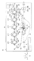
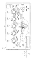
画像形成装置10は、図1に示されるように、トナー像形成部20と、転写装置30と、搬送装置40と、定着装置50と、制御部60と、電源PSと、を含んで構成される電子写真方式の装置とされている。
<Configuration of image forming apparatus>
As shown in FIG. 1, the
[トナー像形成部]
トナー像形成部20は、帯電、露光、現像の各工程を行って、後述するトナー像G(図1参照)を形成する機能を有する。
[Toner image forming section]
The toner
トナー像形成部20は、図1に示されるように、それぞれ異なる色(G(金)、Y(イエロー)、M(マゼンタ)、C(シアン)、K(ブラック))のトナー像Gを形成する単色ユニット21G、21Y、21M、21C、21Kで構成されている。また、単色ユニット21G、21Y、21M、21C、21Kは、後述するN2を基準とすると、後述する転写ベルトTBの移動方向(矢印R方向)上流側から下流側にこれらの記載順で並べられている。単色ユニット21G、21Y、21M、21C、21Kは、それぞれが形成するトナー像Gの色以外は同様の構成とされている。以下、本明細書及び図面において、単色ユニット21G、21Y、21M、21C、21K及びその構成要素を区別する必要がない場合、アルファベット(G、Y、M、C、K)を省略して説明する。なお、以下の説明では、単色ユニット21Gが形成するトナー像Gをトナー像G1とし、単色ユニット21G以外の単色ユニット21が形成するトナー像Gをトナー像G2とする。ただし、特にトナー像G1とトナー像G2とを区別する必要のない場合、トナー像G1及びトナー像G2をトナー像Gと記載する。ここで、トナー像G1及びトナー像G2は、像の一例である。
As shown in FIG. 1, the toner
単色ユニット21Gは、扁平トナーMT(以下、トナーMTという。図4参照)でトナー像G1を形成するようになっている。また、単色ユニット21G以外の単色ユニット21は、非扁平トナーNT(以下、トナーNTという。図5参照)でトナー像G2を形成するようになっている。ここで、単色ユニット21は、形成部の一例である。なお、本実施形態のトナーMT及びトナーNTは、一例として負極性(帯電量分布の平均が負)とされている。以下の説明において、特にトナーMTとトナーNTとを区別する必要のない場合、トナーMT、NTをトナーTと記載する。
The
各単色ユニット21は、図1及び図2に示されるように、円筒の感光体22と、帯電装置24と、露光装置26と、現像装置28と、を含んで構成されている。帯電装置24は感光体22を帯電し、露光装置26は感光体22を露光し(感光体22に潜像を形成し)、現像装置28はトナー像Gを現像し(潜像をトナー像Gに現像し)、トナー像Gを形成するようになっている。なお、露光装置26は、一例として、感光体22に1200dpi×1200dpi(約21μm×約21μm)相当の露光ドットで構成される潜像を形成するようになっている。また、図1では、単色ユニット21K以外の単色ユニット21の構成要素の符号が省略されている。
As shown in FIGS. 1 and 2, each
[転写装置]
転写装置30は、各単色ユニット21が形成したトナー像Gを移動する転写ベルトTBに後述するニップ部N1で1次転写する機能と、1次転写したトナー像Gをニップ部N2に搬送される媒体Pに移動する転写ベルトTBからニップ部N2で2次転写する機能と、を有する。転写装置30は、図1に示されるように、転写ベルトTBと、駆動ロール32と、1次転写ロール34G、34Y、34M、34C、34Kと、2次転写ユニット36と、を含んで構成されている。以下、本明細書及び図面において、1次転写ロール34G、34Y、34M、34C、34Kを区別する必要がない場合、アルファベット(G、Y、M、C、K)を省略して説明する。なお、転写装置30には、制御部60のうち後述する図8のフローチャートに従う制御を行う部分が含まれる。
[Transfer device]
The
〔転写ベルト及び駆動ロール〕
転写ベルトTBは、無端状とされている。また、駆動ロール32は、駆動源(図示省略)により駆動されて、軸周りに回転しながら、転写ベルトTBを矢印R方向に移動させるようになっている。そして、転写ベルトTBは、各単色ユニット21が形成した各トナー像Gを外周に保持しながら、各トナー像Gをニップ部N2へ到達させるようになっている。ここで、転写ベルトTBは、移動体の一例である。
[Transfer belt and drive roll]
The transfer belt TB is endless. The
〔1次転写ロール〕
1次転写ロール34Gは、単色ユニット21Gが形成したトナー像G1を移動する転写ベルトTBにニップ部N1で1次転写する機能を有する。また、1次転写ロール34Y、34M、34C、34Kは、それぞれ単色ユニット21Y、21M、21C、21Kが形成したトナー像G2を移動する転写ベルトTBにニップ部N1で1次転写する機能を有する。
[Primary transfer roll]
The
1次転写ロール34は、導電性ロールとされている。また、各1次転写ロール34は、それぞれ同等の構成とされている。1次転写ロール34G、34Y、34M、34C、34Kは、転写ベルトTBを挟んで、それぞれ単色ユニット21G、21Y、21M、21C、21Kの下側に配置されている。そのため、1次転写ロール34G、34Y、34M、34C、34Kは、ニップ部N2を基準とすると、転写ベルトTBの移動方向上流側から下流側にこれらの記載順で並べられている。つまり、1次転写ロール34Gは、ニップ部N2を基準とすると、1次転写ロール34G以外の1次転写ロール34に対し転写ベルトTBの移動方向上流側に配置されている。ここで、1次転写ロール34Gは1次転写部の一例、1次転写ロール34Y、34M、34C、34Kは他の1次転写部の一例である。
The primary transfer roll 34 is a conductive roll. The primary transfer rolls 34 have the same configuration. The primary transfer rolls 34G, 34Y, 34M, 34C, and 34K are disposed below the
各1次転写ロール34は、それぞれ引っ張りばね(図示省略)により下側に引っ張られ、カム(図示省略)により上下方向に移動可能に構成されている。各1次転写ロール34は、各トナー像Gを転写ベルトTBに1次転写しない場合、転写ベルトTBから離間して待機する待機位置に配置されている。これに対し、各1次転写ロール34は、各トナー像Gを転写ベルトTBに1次転写する場合、カムにより待機位置から移動されて待機位置よりも上側の動作位置に配置され、各感光体22とで転写ベルトTBを挟んで各感光体22と転写ベルトTBとに各ニップ部N1を形成するようになっている。そして、各1次転写ロール34は、電源PSから1次転写電圧(正極性の電圧)が印加されることで、移動する転写ベルトTBに各感光体22に形成された各トナー像Gをニップ部N1で1次転写するようになっている。なお、各1次転写ロール34は、各トナー像Gを1次転写する場合のみ、動作位置に配置され、1次転写電圧が印加されるようになっている。例えば、単色ユニット21G以外の単色ユニット21でトナー像Gを形成しない場合、1次転写ロール34G以外の1次転写ロール34は、待機位置に配置されたまま1次転写電圧が印加されないようになっている。
Each primary transfer roll 34 is pulled downward by a tension spring (not shown) and is movable in the vertical direction by a cam (not shown). Each primary transfer roll 34 is disposed at a standby position where the toner image G is separated from the transfer belt TB and waits when the toner image G is not primarily transferred to the transfer belt TB. On the other hand, each primary transfer roll 34 is moved from the standby position by the cam and is disposed at the operation position above the standby position when the toner image G is primarily transferred to the transfer belt TB. The nip portions N1 are formed between the
〔2次転写ユニット〕
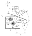
2次転写ユニット36は、図1及び図3に示されるように、2次転写部70と、除去部80と、を含んで構成されている。
[Secondary transfer unit]
As shown in FIGS. 1 and 3, the
〈2次転写部〉
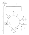
2次転写部70は、転写ベルトTBに1次転写された各トナー像Gを、ニップ部N2で搬送装置40によりニップ部N2に搬送される媒体Pに2次転写する機能を有する。2次転写部70は、図3に示されるように、導電性ロール72と、テンションロール74と、導電性ベルトCBと、バックアップロール76と、可動部78と、を備えている。
<Secondary transfer section>
The
導電性ロール72は、シャフト72Aと、円筒状の導電層72Bと、を有している。そして、導電性ロール72は、駆動源(図示省略)に駆動されて、軸周りに回転するようになっている。導電性ベルトCBは、無端状とされており、円筒状の導電層72Bに巻きかかっている。テンションロール74は、導電性ベルトCBを内周側から押圧して、導電性ベルトCBに張力を付与している。そして、導電性ロール72が軸周りに回転すると、導電性ベルトCBが周回するようになっている。なお、導電性ロール72のシャフト72Aは、接地されている。
The
バックアップロール76(以下、BUR76とする。)は、転写ベルトTBを挟んで導電性ロール72の反対側(上側)であって、導電性ロール72に対して転写ベルトTBの移動方向下流側にオフセットした位置に配置されている。BUR76は、シャフト76Aと、円筒状の導電層76Bと、を有している。
The backup roll 76 (hereinafter referred to as BUR 76) is on the opposite side (upper side) of the
可動部78は、転写ベルトTBの内側に配置されている。可動部78は、BUR76を上下方向に移動させる機能を有する。具体的には、可動部78は、図3に示されるように、一対の軸受78Aと、一対の引っ張りばね(図示省略)と、一対の偏心カム78Bと、シャフト78Cと、駆動源78Dと、を含んで構成されている。一対の軸受78Aは、シャフト76Aの両端側の部分に嵌め込まれている。一対の引っ張りばねの一端は、それぞれ一対の軸受78Aに引っ掛けられた状態で、BUR76を上側に引っ張っている。一対の偏心カム78Bは、シャフト78Cの両端に固定された状態で、それぞれ一対の軸受78Aを下側に押圧している。駆動源78Dは、シャフト78Cを軸周りに回転させるようになっている。そして、駆動源78Dがシャフト78Cを軸周りに回転させると、一対の偏心カム78Bは、一対の軸受78Aを下側に押圧しながら回転するようになっている。以上の構成より、可動部78は、BUR76を上下方向に移動させるようになっている。ここで、図1及び図3は、画像形成動作が実行されている場合の位置(動作位置)に、BUR76が配置されている状態を示している。この場合、BUR76は、導電性ロール72とで、導電性ベルトCBと転写ベルトTBとを挟んで、導電性ベルトCBと転写ベルトTBとにニップ部N2を形成している。
The
また、可動部78は、一対の偏心カム78Bの停止位置(シャフトの停止角度)を変更して、BUR76を上下方向における複数の動作位置に配置可能にしている。その結果、本実施形態の2次転写部70は、BUR76の動作位置を変更して、ニップ部N2のニップ圧(圧)を変更可能にしている。本実施形態の2次転写部70は、一例として3ヶ所の動作位置(第1〜第3位置)にBUR76を配置可能とされている。図1及び図3に示されるBUR76は第1位置に配置されている。なお、第1位置、第2位置、第3位置は、その番号が大きくなるに従い、下側の位置とされている。つまり、可動部78によりBUR76を第1位置よりも第2位置、更に第2位置よりも第3位置に配置させることで、BUR76は、ニップ部N2のニップ圧を高くすることが可能とされている。これに対して、画像形成動作が実行されていない場合(例えば、画像形成動作が実行される前の待機時)、BUR76は、可動部78の一対の偏心カム78Bにより動作位置の上側とされる待機位置(図示省略)に配置されるようになっている。また、BUR76の位置に関わらず、BUR76は転写ベルトTBの内周に接触している。そのため、BUR76が待機位置に配置されている状態では、ニップ部N2が解除されるようになっている。
Moreover, the
可動部78は、制御部60が駆動源を駆動させることで、BUR76の動作位置を変更するようになっている。そこで、可動部78がどのような場合にBUR76の動作位置をどう変更するかについては、後述する制御部60の説明の中で説明する。
The
前述のとおり、画像形成動作、すなわち、転写動作が実行されている期間中、BUR76は、動作位置に配置される。そして、BUR76のシャフト76Aには、電源PSから電圧が印加されるようになっている。具体的には、媒体Pがニップ部N2を通過している期間中、BUR76には電源PSから2次転写電圧(負極性の電圧)が印加され、転写ベルトTBと導電性ベルトCBとがトナー像Gを媒体Pに2次転写する電界をニップ部N2に形成するようになっている。これに対し、媒体Pがニップ部N2を通過する前後において、BUR76には電源PSから正極性の電圧が印加され、転写ベルトTBと導電性ベルトCBとは、ニップ部N2において転写ベルトTBに付着しているかぶりトナー等を転写ベルトTBに保持させる電界を形成するようになっている。 As described above, the BUR 76 is disposed at the operation position during the image forming operation, that is, during the transfer operation. A voltage is applied from the power source PS to the shaft 76A of the BUR 76. Specifically, during the period when the medium P passes through the nip portion N2, a secondary transfer voltage (negative voltage) is applied to the BUR 76 from the power source PS, and the transfer belt TB and the conductive belt CB are connected to the toner. An electric field for secondary transfer of the image G to the medium P is formed in the nip portion N2. On the other hand, before and after the medium P passes through the nip portion N2, a positive voltage is applied to the BUR 76 from the power supply PS, and the transfer belt TB and the conductive belt CB adhere to the transfer belt TB at the nip portion N2. An electric field for holding the fog toner or the like on the transfer belt TB is formed.
〈除去部〉
除去部80は、導電性ベルトCBに付着したトナーT(前述のかぶりトナー等を含むトナー)を除去する機能を有する。除去部80は、図3に示されるように、第1除去部82と、第2除去部84と、ハウジング86と、を備えている。第1除去部82及び第2除去部84は、ハウジング86内に配置されている。
<Removal part>
The removing
第1除去部82は、負極性に帯電しているトナーTを除去する機能を有する。第1除去部82は、導電性ブラシ82Aと、金属製シャフト82Bと、を有している。導電性ブラシ82Aは、導電性ベルトCBに接触している(食い込んでいる)。金属製シャフト82Bは、導電性ブラシ82Aに接触している。第2除去部84は、正極性に帯電しているトナーTを除去する機能を有する。第2除去部84は、第1除去部82よりも導電性ベルトCBの周回方向下流側の部位であってニップ部N2よりも上流側の部位に配置されている。第2除去部84は、導電性ブラシ84Aと、金属製シャフト84Bと、を有している。導電性ブラシ84Aは、導電性ベルトCBに接触している。
The
そして、金属製シャフト84Bが駆動源(図示省略)により駆動されると、金属製シャフト84Bは装置奥行き方向手前側から見て、反時計回りに回転するようになっている。また、導電性ブラシ82A、84A及び金属製シャフト82Bは、金属製シャフト84Bに設けられたギア(図示省略)に噛み合わされたギア(図示省略)を介して、トルクが伝達されるようになっている。その結果、金属製シャフト82Bは反時計回りに、導電性ブラシ82A、84Aは、時計回りに回転するようになっている。以上のとおり、本実施形態では、導電性ブラシ82A、84A及び金属製シャフト82Bは、金属製シャフト84Bの回転に伴い回転し、金属製シャフト84Bの停止に伴い停止するように構成されている。なお、本実施形態では、画像形成動作が実行されている期間中、金属製シャフト84Bが軸周りに回転するようになっている。また、電源PSにより金属製シャフト82Bに正極性の電圧、金属製シャフト84Bに負極性の電圧が印加され、第1除去部82、第2除去部84は、それぞれ負極性のトナーT、正極性のトナーTを除去するようになっている。
When the
[搬送装置]
搬送装置40は、媒体Pを搬送する機能を有する。なお、搬送装置40は、図1及び図3に示されるように、媒体Pを搬送方向CDに搬送するようになっている。
[Conveyor]
The
[定着装置]
定着装置50は、転写装置30により媒体Pに2次転写された各トナー像Gを構成するトナーTをニップ部N3で加熱、加圧して、媒体PにトナーTを定着させる機能を有する。定着装置50は、加熱部50Aと、加圧部50Bと、を含んで構成されている。
[Fixing device]
The fixing
[制御部]
制御部60は、転写装置30を構成する制御部60以外の各部及び画像形成装置10を構成する転写装置30以外の各部(以下、制御部60以外の各部という。)を制御する機能を有する。
[Control unit]
The
制御部60は、外部装置(図示省略)からジョブデータを受け取るように構成されている。ここで、ジョブデータは、データの一例である。ジョブデータを受け取った制御部60は、一例として、図7のフローチャートに従い、制御部60以外の各部を制御するようになっている。そして、制御部60がジョブデータを受け取って上記各部を制御すると、画像形成装置10は、画像形成動作を実行するようになっている。ここで、画像形成装置10が画像形成動作を実行することは、画像形成装置10を構成する転写装置30が転写動作を実行することを含む。なお、ジョブデータには、トナー像Gを各単色ユニット21に形成させる画像データ、画像形成に用いる媒体Pのサイズ、画像形成に用いる媒体Pの幅(媒体Pの搬送方向CDと直交する方向における媒体Pの幅のことをいう。)、枚数のデータ等が含まれている。また、画像データには、各単色ユニット21でトナー像G(又は画像)を形成するため画像密度(%)のデータが含まれている。
The
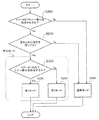
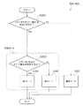
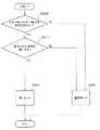
以下、図7のフローチャートに示される制御における判断ステップS200、判断ステップS210及び判断ステップS220について説明し、次いで、通常モード(ステップS250)及び特別モード(判断ステップS210で肯定判断をした場合のモード)について説明する。 Hereinafter, determination step S200, determination step S210, and determination step S220 in the control shown in the flowchart of FIG. 7 will be described, and then a normal mode (step S250) and a special mode (a mode in which an affirmative determination is made in determination step S210). Will be described.
〔判断ステップS200〕
制御部60は、判断ステップS200において、単色ユニット21Gにトナー像G1を形成させるかを判断するようになっている。別の見方をすれば、制御部60は、ジョブデータ(に含まれる画像データ)に、トナー像G1を形成させるデータが含まれているかを判断するようになっている。そして、制御部60は、判断ステップS200において肯定判断した場合、判断ステップS210の判断を行うようになっている。これに対し、制御部60は、判断ステップS200において否定判断をした場合、画像形成装置10が通常モードで画像形成動作を実行するように、制御部60以外の各部を制御するようになっている(ステップS250)。通常モードについては後述する。
[Judgment Step S200]
In the determination step S200, the
〔判断ステップS210〕
制御部60は、判断ステップS210において、形成されるトナー像G1が定められた条件を満たすかを判断するようになっている。ここで、定められた条件を満たすとは、以下の第1条件を満たすこと、かつ、第2条件を満たすこととされている。
[Judgment Step S210]
In the determination step S210, the
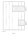
第1条件は、形成されるトナー像G1の画像幅の比率R1が予め定められた比率R2(以下、基準比率R2という。)よりも大きいこととされている。ここで、画像幅は、トナー像G1における媒体Pの幅方向に沿った幅のうち最大幅とされている。そして、画像幅の比率R1は、実際の画像形成に用いる媒体Pの幅に対するトナー像G1における媒体Pの幅方向に沿った幅のうち最大幅の比率とされている。また、基準比率R2とは、実際の画像形成に用いる媒体Pの幅に対する予め定められた比率とされている。本実施形態の予め定められた比率は、一例として1/2(50%)とされている(図9参照)。別の見方をすれば、第1条件は、形成されるトナー像G1の画像幅が予め定められた幅(媒体Pの幅に基準比率R2を乗じた幅)よりも大きいこととされている。 The first condition is that the image width ratio R1 of the toner image G1 to be formed is larger than a predetermined ratio R2 (hereinafter referred to as a reference ratio R2). Here, the image width is the maximum width among the widths along the width direction of the medium P in the toner image G1. The image width ratio R1 is the ratio of the maximum width of the widths of the toner image G1 along the width direction of the medium P to the width of the medium P used for actual image formation. The reference ratio R2 is a predetermined ratio with respect to the width of the medium P used for actual image formation. The predetermined ratio of this embodiment is ½ (50%) as an example (see FIG. 9). From another viewpoint, the first condition is that the image width of the toner image G1 to be formed is larger than a predetermined width (a width obtained by multiplying the width of the medium P by the reference ratio R2).
第2条件は、形成されるトナー像G1の画像密度C1が予め定められた密度(以下、基準密度C2という。)よりも高いこととされている。ここで、トナーMTの画像密度は、露光装置26が感光体22上に形成する露光ドットを1画素とした場合、単位面積当たり含まれる総画素数に対してトナー像G1が現像装置28により現像される画素数の百分率をいう。本実施形態の基準密度C2は、一例として95%とされている(図9参照)。
The second condition is that the image density C1 of the formed toner image G1 is higher than a predetermined density (hereinafter referred to as a reference density C2). Here, the image density of the toner MT is such that the toner image G1 is developed by the developing
そして、制御部60は、判断ステップS210において肯定判断をした場合、画像形成装置10が特別モード(後述する第1モード又は第2モード)で画像形成動作を実行するように、制御部60以外の各部を制御するようになっている。なお、制御部60が判断ステップS210において肯定判断をした場合は、ジョブデータに含まれるトナー像G1のデータが図9における領域A1に含まれる場合とされる。この場合、画像形成装置10が特別モードで画像形成動作を実行するとした理由については、本実施形態の作用の説明の中で説明する。
Then, when the
〔判断ステップS220〕
制御部60は、判断ステップS220において、トナー像G1のみであるかを判断するようになっている。別の見方をすれば、制御部60は、判断ステップS220において、トナー像G1のみを2次転写するかを判断するようになっている。そして、制御部60は、判断ステップS220において肯定判断をした場合、画像形成装置10が第1モード(ステップS230)で画像形成動作を実行するように、制御部60以外の各部を制御するようになっている。これに対して、制御部60は、判断ステップS220において否定判断をした場合、画像形成装置10が第2モード(ステップS240)で画像形成動作を実行するように、制御部60以外の各部を制御するようになっている。
[Judgment Step S220]
In the determination step S220, the
〔通常モード及び特別モード〕
次に、通常モード及び特別モード(特別モードにおいては第1モード及び第2モード)について説明する。制御部60は、図7のフローチャートに従い何れかのモードを選択すると、可動部78の駆動源78Dによりシャフト78Cを回転、停止させ、BUR76を待機位置から各モードに対応する第1〜3位置の何れか1つの動作位置に移動させるようになっている。そして、画像形成装置10は、BUR76が各モードに対応する第1〜3位置の何れか1つの動作位置に配置されている状態で画像形成動作を実行するようになっている。
[Normal mode and special mode]
Next, the normal mode and the special mode (the first mode and the second mode in the special mode) will be described. When one of the modes is selected according to the flowchart of FIG. 7, the
〈通常モード〉
通常モードは、BUR76が前述の第1位置(図1及び図2のBUR76の位置)に配置された状態で、画像形成装置10が画像形成動作を実行するモードとされている。
<Normal mode>
The normal mode is a mode in which the
〈第1モード〉
第1モードは、BUR76が前述の第2位置に配置された状態で、画像形成装置10が画像形成動作を実行するモードとされている。そのため、第1モードにおけるニップ部N2のニップ圧(第1圧の一例)は、図8に示されるように、通常モードにおけるニップ部N2のニップ圧(第2圧の一例)よりも高い。
<First mode>
The first mode is a mode in which the
〈第2モード〉
第2モードは、BUR76が前述の第3位置に配置された状態で、画像形成装置10が画像形成動作を実行するモードとされている。そのため、第2モードにおけるニップ部N2のニップ圧(第1圧の一例)は、図8に示されるように、通常モードにおけるニップ部N2のニップ圧(第2圧の一例)よりも高い。また、第2モードにおけるニップ部N2のニップ圧は、第1モードにおけるニップ部N2のニップ圧よりも高い。
<Second mode>
The second mode is a mode in which the
以上が、本実施形態の画像形成装置10の全体の構成についての説明である。
The above is the description of the overall configuration of the
<トナー>
[扁平トナー(トナーMT)]
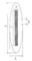
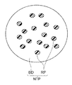
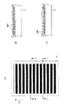
トナーMTを構成するトナー粒子MTPは、一例として、図4に示されるように、金属顔料MPと、バインダーBDと、を含んで構成されている。バインダーBDは、金属顔料MPを覆っている。金属顔料MPは、扁平とされている。具体的には、金属顔料MPの長軸長さL1がは一例として5μm以上12μm以下、その厚みT1が一例として0.01μm以上0.5μm以下とされている。ここで、長軸長さL1とは、金属顔料MPの厚み方向と直交する方向から金属顔料MPを見た場合、金属顔料MPの最も長い部分の長さをいう。そして、本実施形態のトナー粒子MTPは、その長軸長さL2が一例として7μm以上20μm以下、その厚みT2が一例として1μm以上3μm以下とされている。ここで、長軸長さL2とは、トナー粒子MTPの厚み方向と直交する方向からトナー粒子MTPを見た場合、トナー粒子MTPの最も長い部分の長さをいう。以上のとおり、本実施形態のトナー粒子MTPは、含有されている金属顔料MPの長軸長さL1/厚みT1が一例として10以上1200以下であって、トナー粒子MTPの長軸長さL1/厚みT2が一例として2.3以上20以下の関係を有するトナー粒子をいう(そして、本実施形態のトナーMTは、上記の関係を有するトナー粒子MTPの集合体をいう)。なお、前述のとおり、本実施形態のトナーMTは金色であるが、トナー粒子MTPを構成する金属顔料MPは一例としてアルミとされ、バインダーBDに一例としてイエロー(Y)の顔料を分散させることで、金色とされている。
<Toner>
[Flat toner (toner MT)]
As an example, the toner particles MTP constituting the toner MT include a metal pigment MP and a binder BD as shown in FIG. The binder BD covers the metal pigment MP. The metal pigment MP is flat. Specifically, the major axis length L1 of the metal pigment MP is 5 μm or more and 12 μm or less as an example, and the thickness T1 is 0.01 μm or more and 0.5 μm or less as an example. Here, the major axis length L1 refers to the length of the longest portion of the metal pigment MP when the metal pigment MP is viewed from a direction orthogonal to the thickness direction of the metal pigment MP. The major axis length L2 of the toner particles MTP of the present embodiment is, for example, 7 μm or more and 20 μm or less, and the thickness T2 is, for example, 1 μm or more and 3 μm or less. Here, the major axis length L2 refers to the length of the longest portion of the toner particles MTP when the toner particles MTP are viewed from a direction orthogonal to the thickness direction of the toner particles MTP. As described above, in the toner particles MTP of the present embodiment, the major axis length L1 / thickness T1 of the contained metal pigment MP is 10 or more and 1200 or less, and the major axis length L1 / of the toner particles MTP is an example. For example, toner particles having a thickness T2 having a relationship of 2.3 or more and 20 or less (and toner MT of the present embodiment refers to an aggregate of toner particles MTP having the above relationship). As described above, the toner MT of the present embodiment is gold, but the metal pigment MP constituting the toner particles MTP is aluminum as an example, and yellow (Y) pigment is dispersed as an example in the binder BD. , And gold.
[非扁平トナー(トナーNT)]
トナーNTを構成するトナー粒子NTPは、一例として、図5に示されるように、樹脂顔料RPと、バインダーBDと、を含んで構成されている。また、トナー粒子NTPは、非扁平とされている。具体的には、本実施形態のトナー粒子NTPは、含有されている樹脂顔料RPの長軸長さ/厚みが一例として10未満であって、トナー粒子NTPの長軸長さ/厚みが一例として2.3未満の関係を有するトナー粒子をいう。また、本実施形態のトナー粒子NTPを平面に投影した場合の円形度は、一例として、0.90以上とされている。以上より、本実施形態のトナー粒子NTP(トナーNT)は、非扁平のトナー粒子(トナー)とされている。
[Non-flat toner (toner NT)]
As an example, the toner particle NTP constituting the toner NT includes a resin pigment RP and a binder BD as shown in FIG. Further, the toner particles NTP are non-flat. Specifically, in the toner particle NTP of the present embodiment, the major axis length / thickness of the resin pigment RP contained is less than 10 as an example, and the major axis length / thickness of the toner particle NTP is an example. Toner particles having a relationship of less than 2.3. In addition, the circularity when the toner particles NTP of the present embodiment are projected onto a plane is, for example, 0.90 or more. As described above, the toner particles NTP (toner NT) of the present embodiment are non-flat toner particles (toner).
以上が、本実施形態の画像形成装置10が用いるトナーMT、NTについての説明である。
This completes the description of the toners MT and NT used by the
<補足>
[補足1]
トナーMTは、図6(A)及び(B)に示されるように、転写ベルトTBとともにニップ部N1、N2以外の部位を移動している期間中、転写ベルトTBの外周に対してほぼ直交する方向にその長軸(長手方向の軸)が沿った状態(立った状態)で、転写ベルトTBに付着している。これは、トナーMTがその長軸方向に沿った方向に分極しているためと推認される。なお、転写ベルトTBに立った状態で付着しているトナーMTは、ニップ部N1では感光体22と転写ベルトTBとに挟まれて、ニップ部N2では転写ベルトTBと2次転写部70の導電性ベルトCBとに挟まれて、倒れると推認される。
<Supplement>
[Supplement 1]
As shown in FIGS. 6A and 6B, the toner MT is substantially orthogonal to the outer periphery of the transfer belt TB during the period in which the toner MT moves along with the transfer belt TB other than the nip portions N1 and N2. It adheres to the transfer belt TB with its long axis (longitudinal axis) along the direction (standing position). This is presumably because the toner MT is polarized in the direction along the long axis direction. The toner MT attached while standing on the transfer belt TB is sandwiched between the
[補足2]
本実施形態の画像形成装置10は、前述のとおり、単色ユニット21Gを用いてトナー像G1を形成すると、扁平な金属顔料MPを色素とした画像を形成するようになっている。このように扁平な金属顔料MPを含むトナー粒子MTPで構成されるトナーMTを用いて画像を形成すると、当該画像は、光を反射して金属光沢感を生じさせる。
[Supplement 2]
As described above, when the toner image G1 is formed by using the
<画像形成装置の画像形成動作>
次に、本実施形態の画像形成装置10の画像形成動作について、図面を参照しつつ説明する。まず、画像形成装置10の基本的動作について説明し、次いで、外部装置(図示省略)から受け取った異なるジョブデータごとの動作について説明する。画像形成装置10の基本的動作とは、ジョブデータが異なる場合であっても共通して行われる動作のことを意味する。
<Image Forming Operation of Image Forming Apparatus>
Next, an image forming operation of the
[基本的動作]
外部装置(図示省略)からジョブデータを受け取った制御部60は、制御部60以外の各部であるトナー像形成部20、転写装置30及び定着装置50を作動させる。
[Basic operation]
Upon receiving job data from an external device (not shown), the
制御部60は、各帯電装置24に各感光体22を帯電させ、各露光装置26に各感光体22を露光させ、各現像装置28に各トナー像Gを現像させて、各単色ユニット21にトナー像Gを形成させる。また、制御部60は、カムにより各1次転写ロール34を動作位置に配置させ、電源PSから各1次転写ロール34に1次転写電圧を印加させる。その結果、各単色ユニット21が形成した各トナー像Gは、各ニップ部N1で移動する転写ベルトTBに1次転写される。
The
また、制御部60は、駆動源により2次転写ユニット36の可動部78のシャフトを回転、停止させ、BUR76を待機位置から各モード(通常モード、第1モード及び第2モードの何れかのモード)に対応する動作位置に移動させる。また、制御部60は、別の駆動源を駆動させ、2次転写部ユニット36の導電性ベルトCBを周回させ、導電性ブラシ92A、94Aを軸周りに回転させる。また、制御部60は、定着装置50の加熱部50Aを加熱させる。
Further, the
次いで、制御部60は、転写ベルトTB上の各トナー像Gが転写ベルトTBとともにニップ部N2に到達するタイミングに合わせて、搬送装置40に媒体PをN2に向けて搬送させる。そして、制御部60は、電源PSからBUR76のシャフト76Aに2次転写電圧が印加させる。その結果、転写ベルトTB上の各トナー像Gは、ニップ部N2を通過する媒体Pに2次転写される。
Next, the
次いで、制御部60は、搬送装置40に媒体Pを定着装置50のニップ部N3に向けて搬送させる。そして、制御部60は、媒体Pに2次転写された各トナー像Gを構成するトナーTを加熱部50Aに加熱、加圧部50Bに加圧させる。その結果、媒体P上の各トナー像Gは、媒体Pに定着される。そして、各トナー像Gが定着された媒体P(画像が形成された媒体P)は、搬送装置40により画像形成装置10の外に排出されて、画像形成装置10の画像形成動作が終了する。
Next, the
なお、導電性ベルトCBに付着したトナーT(前述のかぶりトナー等)は、導電性ベルトCBとともに周回し、除去部90により導電性ベルトCB上から除去される。
The toner T (such as the above-mentioned fog toner) adhering to the conductive belt CB circulates together with the conductive belt CB and is removed from the conductive belt CB by the removing
以上が、画像形成装置10の基本的動作についての説明である。
The basic operation of the
[ジョブデータごとの動作]
次に、外部装置(図示省略)から受け取った異なるジョブデータごとの動作について図7を参照しつつ説明する。
[Operation for each job data]
Next, the operation for each different job data received from an external device (not shown) will be described with reference to FIG.
〔ジョブデータにトナー像G1を形成させるデータが含まれていない場合〕
制御部60は、判断ステップS200で否定判断をして、ステップS250に従い通常モードで制御部60以外の各部を制御する。そのため、制御部60は、BUR76を通常モードに対応する第1位置に配置させて、2次転写部70に2次転写動作をさせる。そして、画像形成装置10により画像形成が要求された媒体Pへの画像形成が実行されて、画像形成動作が終了する。
[When the data for forming the toner image G1 is not included in the job data]
The
〔ジョブデータにトナー像G1を形成させるデータが含まれている場合〕
以下、3つのケースに分けて説明する。なお、これらのケースでは、制御部60は、前提として判断ステップS200において肯定判断して、判断ステップS210の判断を行う。
[When job data includes data for forming toner image G1]
Hereinafter, the description will be divided into three cases. In these cases, the
〈トナー像G1のデータが予め定められた条件を満たしていないケース〉
このケースは、トナー像G1のデータが図9における領域A1に含まれていないケースとされる。制御部60は、判断ステップS210で否定判断をして、ステップS250に従い通常モードで制御部60以外の各部を制御する。そのため、制御部60は、BUR76を通常モードに対応する第1位置に配置させて、2次転写部70に2次転写動作をさせる。そして、画像形成装置10により画像形成が要求された媒体Pへの画像形成が実行されて、画像形成動作が終了する。
<Case where data of toner image G1 does not satisfy a predetermined condition>
In this case, the data of the toner image G1 is not included in the area A1 in FIG. The
〈トナー像G1のデータが予め定められた条件を満たし、トナー像G1のみを形成するケース〉
このケースは、トナー像G1のデータが図9における領域A1に含まれており、かつ、単色ユニット21Gのみでトナー像Gを形成するケースとされる。制御部60は、判断ステップS220で肯定判断をして、ステップS230に従い第1モードで制御部60以外の各部を制御する。そのため、制御部60は、BUR76を第1モードに対応する第2位置に配置させて、2次転写部70に2次転写動作をさせる。そして、画像形成装置10により画像形成が要求された媒体Pへの画像形成が実行されて、画像形成動作が終了する。
<Case where data of toner image G1 satisfies a predetermined condition and only toner image G1 is formed>
In this case, the data of the toner image G1 is included in the area A1 in FIG. 9, and the toner image G is formed only by the
〈トナー像G1のデータが予め定められた条件を満たし、トナー像G1及びトナー像G2を形成するケース〉
このケースは、トナー像G1のデータが図9における領域A1に含まれており、かつ、単色ユニット21Gでトナー像G1を、単色ユニット21G以外の単色ユニット21の1つ以上でトナー像G2を形成するケースとされる。制御部60は、判断ステップS220で否定判断をして、ステップS240に従い第2モードで制御部60以外の各部を制御する。そのため、制御部60は、BUR76を第2モードに対応する第3位置に配置させて、2次転写部70に2次転写動作をさせる。そして、画像形成装置10により画像形成が要求された媒体Pへの画像形成が実行されて、画像形成動作が終了する。
<Case where toner image G1 data satisfies predetermined conditions and forms toner image G1 and toner image G2>
In this case, data of the toner image G1 is included in the area A1 in FIG. 9, and the toner image G1 is formed by the
以上が、本実施形態の画像形成装置10の画像形成動作についての説明である。
The above is the description of the image forming operation of the
<作用>
次に、本実施形態の作用について説明する。
<Action>
Next, the operation of this embodiment will be described.
まず、本実施形態の作用について図面を参照しつつ説明する。なお、以下の説明において、本実施形態の作用を比較形態(第1〜第4比較形態)の作用と比較して行う場合であって、比較形態に本実施形態で用いた部品等と同じ部品等を用いる場合、その部品等の符号をそのまま用いる。 First, the operation of the present embodiment will be described with reference to the drawings. In addition, in the following description, it is a case where the effect | action of this embodiment is compared with the effect | action of a comparison form (1st-4th comparison form), Comprising: The same components as the components etc. which were used by this embodiment for the comparison form Etc. are used as they are.
[第1の作用]
第1の作用については、本実施形態の転写装置30及び画像形成装置10を以下に説明する第1比較形態の転写装置及び画像形成装置(図示省略)と比較して説明する。
[First action]
The first operation will be described by comparing the
第1比較形態の画像形成装置は、2次転写部を構成するBUR76が2次転写動作の際には第1位置に配置されるようになっている。そのため、第1比較形態の画像形成装置は、何れのトナー像Gを形成する場合であっても、本実施形態の通常モードと同様のモードで画像形成動作を行うようになっている。別の見方をすると、第1比較形態の画像形成装置は、何れのトナー像Gを形成する場合であっても、ニップ部N2のニップ圧は本実施形態の画像形成装置10における通常モードのニップ圧(図8参照)とされている。第1比較形態の転写装置及び画像形成装置は、上記の点以外は、本実施形態の画像形成装置10と同様の構成とされている。また、第1比較形態の画像形成装置の画像形成動作は、本実施形態の画像形成装置10の画像形成動作との関係において、制御部60がジョブデータを受け取った後、図7のフローチャートの判断を行わない点以外は、本実施形態の画像形成装置10の場合と同様とされている。
In the image forming apparatus of the first comparative form, the BUR 76 constituting the secondary transfer unit is arranged at the first position during the secondary transfer operation. For this reason, the image forming apparatus of the first comparative embodiment performs an image forming operation in the same mode as the normal mode of the present embodiment, regardless of which toner image G is formed. From another viewpoint, in the image forming apparatus of the first comparative embodiment, the nip pressure of the nip portion N2 is the nip in the normal mode in the
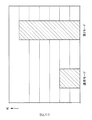
第1比較形態の画像形成装置では、本実施形態の画像形成装置10と同様、画像形成動作が行われる期間中、制御部60は、2次転写ユニット36を構成する金属製シャフト94Bの駆動源(図示省略)を駆動させる。これに伴い、金属製シャフト94Bは軸周りに回転し、導電性ロール72は、導電性ブラシ82A、84A及び金属製シャフト82B、84Bのギア(図示省略)の回転に伴い振動する。そして、導電性ロール72の振動に伴い、導電性ベルトCBも、装置奥行き方向及び装置高さ方向に振動する。その結果、第1比較形態の場合、転写ベルトTBに立った状態で付着しているトナーMTは、2次転写の際に、その通過するタイミングに応じて媒体Pの厚み方向に対してトナーMTの傾斜角度が周期的に変化される。例えば、金属製シャフト94Bが軸周りに回転し、導電性ロール72は、導電性ブラシ82A、84A及び金属製シャフト82B、84Bのギア(図示省略)の回転に伴い装置奥行き方向及び装置高さ方向に振動する場合、トナーMTは、装置奥行き方向手前側又は奥側(媒体Pの幅方向一方側又は他方側)に交互に倒れて媒体Pに2次転写される。そのため、2次転写されたトナー像G1を構成するトナーMTが媒体Pに定着されると、扁平な金属顔料MPは、図11(A)〜(C)に示されるように、導電性ロール72の振動周期で交互に媒体Pの幅方向一方側又は他方側に倒れた状態となっている。そして、トナー像G1のデータが図9における領域A1に含まれている場合、第1比較形態の画像形成装置で形成した画像は、扁平な金属顔料MPの姿勢の周期的なばらつきの大きさが顕著となる。
In the image forming apparatus according to the first comparative embodiment, as in the
ここで、トナーMTは、トナー像G1の幅が広いほど、画像密度C1が高いほど、ニップ部N2において転写ベルトTBと媒体Pとの間で滑り易いと推認される。また、前述のとおり、導電性ベルトCBは、例えば、装置奥行き方向及び装置高さ方向に振動することから、トナーMTは、トナー像G1の形成される幅が広いほど、トナーMTの画像密度C1が高いほど、ニップ部N2で滑って装置奥行き方向(導電性ベルトCBの振動方向)に倒れ易くなると推認される。そして、本願の発明者は、トナー像G1のデータが図10における領域A2内の場合、扁平な金属顔料MPの姿勢の周期的なばらつきが大きい画像が形成されることの知見を得た。そこで、本実施形態では、図10の領域A2のすべてを含み、比率R1と画像密度C1とで表される2次元領域において基準比率R2と基準密度C2とを閾値として簡単に特定できる図10の領域A1を、予め定められた条件を満たす領域とした。なお、図10の領域A2における媒体Pの幅に対するトナー像G1の画像幅の比率の下限は1/2(50%)を越え、画像密度C1の下限は95%を越えている。 Here, it is presumed that the toner MT slips more easily between the transfer belt TB and the medium P at the nip portion N2 as the width of the toner image G1 is wider and the image density C1 is higher. Further, as described above, the conductive belt CB vibrates in the apparatus depth direction and the apparatus height direction, for example. Therefore, the toner MT has an image density C1 of the toner MT as the width of the toner image G1 is increased. It is presumed that the higher the is, the easier it is to slip at the nip portion N2 and to fall in the apparatus depth direction (vibration direction of the conductive belt CB). The inventors of the present application have found that when the data of the toner image G1 is in the area A2 in FIG. 10, an image having a large periodic variation in the posture of the flat metal pigment MP is obtained. Therefore, in the present embodiment, it is possible to easily specify the reference ratio R2 and the reference density C2 as threshold values in a two-dimensional area represented by the ratio R1 and the image density C1 including all of the area A2 in FIG. The region A1 is a region that satisfies a predetermined condition. Note that the lower limit of the ratio of the image width of the toner image G1 to the width of the medium P in the area A2 in FIG. 10 exceeds 1/2 (50%), and the lower limit of the image density C1 exceeds 95%.
これに対して、本実施形態の画像形成装置10では、図7に示されるように、制御部60は、判断ステップS200及び判断ステップS210で肯定判断をした場合、判断ステップS220の判断を行う。そして、本実施形態の制御部60は、判断ステップS220の判断において何れの判断をした場合あっても画像形成装置10が第1モード又は第2モードで画像形成動作を実行するように、制御部60以外の各部を制御する。つまり、本実施形態の転写装置30は、特別モードにおけるニップ部N2のニップ圧を、通常モードにおけるニップ部N2のニップ圧よりも高くして、転写動作を実行する。
On the other hand, in the
そして、導電性ロール72は、ニップ部N2のニップ圧が高いほど、導電性ブラシ82A、84A及び金属製シャフト82B、84Bのギア(図示省略)の回転に伴い、振動し難くなる(振動の振幅が小さくなる)。そのため、特別モードにおける導電性ロール72は、通常モードにおける導電性ロール72に比べて、振動し難い。そして、導電性ロール72は各モードにより振幅の大きさに違いが生じることから、トナーMTは、ニップ部N2のニップ圧が高いほどニップ部N2で滑り難いと推認される。すなわち、本実施形態の転写装置30により媒体Pに2次転写されるトナー像G1は、第1比較形態の転写装置により媒体Pに2次転写されるトナー像G1に比べて、ニップ部N2で滑り難いと推認される。
The
したがって、本実施形態の転写装置30によれば、トナー像G1を2次転写する場合のニップ圧をトナー像G2のみを2次転写する場合のニップ圧よりも高くできない転写装置に比べて、トナー像G1の媒体Pへの2次転写の際に、トナーMTの傾斜角度を媒体Pの厚み方向に対して周期的に変化させ難い。これに伴い、本実施形態の画像形成装置10によれば、トナー像G1を2次転写する場合のニップ圧をトナー像G2のみを2次転写する場合のニップ圧よりも高くできない転写装置を備えた画像形成装置に比べて、扁平な金属顔料MPの姿勢の周期的なばらつきが小さい画像を形成することができる。
Therefore, according to the
[第2の作用]
第2の作用については、本実施形態の転写装置30及び画像形成装置10を以下に説明する第2比較形態の転写装置30A及び画像形成装置10Aと比較して説明する。
[Second action]
The second operation will be described by comparing the
第2比較形態の画像形成装置10Aは、図12のフローチャートのとおり、本実施形態の画像形成装置10(図7参照)と比べると、判断ステップS210がない。そのため、第2比較形態の制御部60は、本実施形態における判断ステップS210の定められた条件を満たすかについて判断しない。そして、第2比較形態の制御部60は、単色ユニット21Gにトナー像G1を形成させる場合(判断ステップS200で肯定判断をした場合)、定められた条件を満たすか否かに関わらず、判断ステップS220を判断する。第2比較形態の転写装置30A及び画像形成装置10Aは、上記の点以外は、第1実施形態の転写装置30及び画像形成装置10と同様の構成とされている。また、第2比較形態の画像形成装置10Aの画像形成動作は、本実施形態の画像形成装置10の画像形成動作との関係において、制御部60が判断ステップS210の判断を行わない点以外は、本実施形態の画像形成装置10の場合と同様とされている。なお、第2比較形態の転写装置30A及び画像形成装置10Aは、本発明の技術的範囲に属する。
The
第2比較形態の画像形成装置10Aは、ジョブデータに含まれるトナー像G1のデータが図9における領域A1に含まれる場合、通常モードで画像形成動作を実行する画像形成装置に比べて、扁平な金属顔料MPの姿勢の周期的なばらつきが小さい(姿勢の周期的なばらつきが抑制された)画像を形成することができる。しかしながら、第2比較形態の画像形成装置10Aは、ジョブデータに含まれるトナー像G1の画像幅の比率R1が基準比率R2以下であり、かつ、画像密度C1が基準密度C2よりも高い場合、特別モードで画像形成動作を実行する。つまり、第2比較形態の画像形成装置10Aは、画像密度C1が基準密度C2よりも高い場合、ニップ部N2のニップ圧が通常モードより高い第1モード又は第2モードで画像形成動作を実行する。
The
これに対して、本実施形態の画像形成装置10は、図7に示されるように、ジョブデータに含まれるトナー像G1の画像幅の比率R1が基準比率R2以下であり、かつ、画像密度C1が基準密度C2よりも高い場合、制御部60が判断ステップS210で肯定判断し、通常モードで画像形成動作を実行する。すなわち、本実施形態の画像形成装置10は、画像密度C1が基準密度C2よりも高い場合、ニップ部N2のニップ圧が通常モードより高い第1モード又は第2モードで画像形成動作を実行しない。そのため、本実施形態の画像形成装置10は、ジョブデータに含まれるトナー像G1のデータが図9の領域A1に含まれる場合(特別モードの制御が必要な場合)、ニップ部N2のニップ圧を高くする。
On the other hand, as shown in FIG. 7, in the
したがって、本実施形態の転写装置30によれば、予め定められた条件を満たすかを判断しない転写装置に比べて、適切な条件においてニップ部N2のニップ圧を高くすることができる。
Therefore, according to the
[第3の作用]
第3の作用については、本実施形態の転写装置30及び画像形成装置10を以下に説明する第3比較形態の転写装置(図示省略)及び画像形成装置(図示省略)と比較して説明する。
[Third action]
The third action will be described by comparing the
第3比較形態の画像形成装置は、画像幅の比率R1を転写ベルトTBにおけるトナー像Gが形成可能な最大の幅(以下、形成可能最大幅という。)に対する実際にトナー像Gが形成される幅の比率とし、基準比率R2を形成可能幅に対する予め定められた幅の比率(一例として50%)としている。そして、第3比較形態の画像形成装置の制御部60は、画像幅の比率R1及び基準比率R2を転写ベルトTBにおける形成可能最大幅に対する比率として、判断ステップS210を行う。第3比較形態の転写装置及び画像形成装置は、上記の点以外は本実施形態の転写装置30及び画像形成装置10と同様の構成とされている。また、第3比較形態の画像形成装置の画像形成動作は、本実施形態の画像形成装置10の画像形成動作との関係において、上記の点以外は本実施形態の画像形成装置10の場合と同様とされている。なお、第3比較形態の画像形成装置は、本発明の技術的範囲に属する。
In the image forming apparatus of the third comparative embodiment, the toner image G is actually formed with respect to the maximum width in which the toner image G can be formed on the transfer belt TB (hereinafter referred to as the maximum width that can be formed). The width ratio is set, and the reference ratio R2 is a ratio of a predetermined width to the formable width (50% as an example). Then, the
第3比較形態の転写装置は、トナー像G1のデータが図9における領域A1に含まれる場合であっても当該データが第3比較形態の基準比率R2以下のときに特別モードを実行しない場合がある。例えば、形成可能最大幅が280mmとすれば予め定められた幅は140mmとなる。この場合、第3比較形態の転写装置で幅100mmの媒体Pに、画像密度C1が基準密度C2より高く、かつ、画像幅が50mm(媒体Pの幅に対する画像幅の比率が50%)よりも大きいトナー像G1を転写するに際し、制御部60は特別モードを選択しない。つまり、第3比較形態の転写装置は、姿勢の周期的なばらつきが小さい画像が形成される条件において、ニップ部N2のニップ圧が通常モードにおけるニップ部N2のニップ圧のままの場合がある。
The transfer device of the third comparison form may not execute the special mode when the data of the toner image G1 is included in the area A1 in FIG. 9 when the data is less than the reference ratio R2 of the third comparison form. is there. For example, if the maximum formable width is 280 mm, the predetermined width is 140 mm. In this case, the image density C1 is higher than the reference density C2 and the image width is 50 mm (ratio of the image width to the width of the medium P is 50%) on the medium P having a width of 100 mm in the transfer device of the third comparative form. When transferring the large toner image G1, the
これに対して、本実施形態の制御部60は、画像幅の比率R1及び基準比率R2を実際の画像形成に用いる媒体Pの幅ごとに対する比率として、判断ステップS210を行う。そのため、本実施形態の制御部60は、実際の画像形成に用いる媒体Pの幅に応じて、比率R1及び基準比率R2を変更することができる。
On the other hand, the
したがって、本実施形態の転写装置30によれば、用いる媒体Pの幅に応じて2次転写時のニップ部N2のニップ圧を変更することができる。
Therefore, according to the
[第4の作用]
第4の作用については、本実施形態の転写装置30及び画像形成装置10を以下に説明する第4比較形態の転写装置(図示省略)及び画像形成装置(図示省略)と比較して説明する。
[Fourth action]
The fourth operation will be described by comparing the
第4比較形態の転写装置30B及び画像形成装置10Bは、図13のフローチャートのとおり、本実施形態の画像形成装置10(図7参照)と比べると、判断ステップS220及びステップS230がない。そして、第4比較形態の制御部60は、判断ステップS210で肯定判断をした場合、画像形成装置10Bに第2モードで画像形成動作を実行させる。別の見方をすると、第4比較形態の転写装置30Bは、図14に示されるように、トナー像G1のみを形成するか否かに関わらず、ニップ部N2のニップ圧は、第2モードのニップ圧とされる。第4比較形態の転写装置30B及び画像形成装置10Bは、上記の点以外は本実施形態の転写装置30及び画像形成装置10と同様の構成とされている。また、第4比較形態の画像形成装置の画像形成動作は、本実施形態の画像形成装置10の画像形成動作との関係において、上記の点以外は本実施形態の画像形成装置10の場合と同様とされている。なお、第4比較形態の転写装置30B及び画像形成装置10Bは、本発明の技術的範囲に属する。
As shown in the flowchart of FIG. 13, the transfer device 30B and the image forming device 10B according to the fourth comparative embodiment do not include the determination step S220 and the step S230 as compared with the
第4比較形態では、例えば、すべての単色ユニット21を用いてすべてのトナー像Gを1次転写する場合、トナー像G1は、5ヶ所のニップ部N1を通過してニップ部N2に到達する。これに対し、単色ユニット21Gのみを用いてトナー像Gを1次転写する場合、1次転写されたトナー像G1は、1ヶ所のニップ部N1を通過してニップ部N2に到達する。前者のトナー像G1を構成するトナーMTは、後者のトナー像G1を構成するトナーMTに比べて、N1を通過する回数が多い分、より負極性に帯電されて、ニップ部N2に到達する。そのため、第2モードのニップ部N2のニップ圧でニップしてトナー像G1を媒体Pに2次転写する場合、後者のトナー像G1を構成するトナーMTは、前者のトナー像G1を構成するトナーMTに比べて、媒体Pに対して静電気的に付着する力が小さい。その結果、第4比較形態では、後者のトナー像G1を構成するトナーMTが媒体Pとともに第2モードのニップ圧でニップされたニップ部N2を通過した直後、トナーMTが媒体Pから飛び散る虞がある。なお、ニップ部N2では、ニップ部N2の上流側から下流側に亘って転写ベルトTB及び媒体Pとともに空気流が発生する。そして、この空気流を構成する空気は、ニップ部N2で圧縮され、更にニップ部N2を通過した後に膨張する(ニップ部N2通過前に戻る)。これに伴い、媒体Pに2次転写されたトナーMTは、ニップ部N2を通過した後に膨張する空気の影響で、飛び散る虞がある。
In the fourth comparative embodiment, for example, when all the toner images G are primarily transferred using all the
これに対して、本実施形態では、トナー像G1のみを2次転写する場合、ニップ部N2のニップ圧は、第2モードの場合よりも低い第1モードのニップ圧とされる。そのため、第1モードにおけるニップ部N2に挟まれた空気の圧縮率は、第2モードにおけるニップ部N2に挟まれた空気の圧縮率に比べて、小さい。その結果、本実施形態の転写装置30は、第4比較形態の転写装置30Bに比べて、トナー像G1のみを2次転写する場合、トナー像G1の飛散量が低減される。
On the other hand, in this embodiment, when only the toner image G1 is secondarily transferred, the nip pressure of the nip portion N2 is set to the nip pressure of the first mode lower than that in the second mode. Therefore, the compression rate of the air sandwiched between the nip portions N2 in the first mode is smaller than the compression rate of the air sandwiched between the nip portions N2 in the second mode. As a result, the
したがって、本実施形態の転写装置30によれば、トナー像G1を2次転写する場合のニップ部N2のニップ圧をトナー像G1及びトナー像G2を2次転写する場合のニップ部N2のニップ圧と同等とする転写装置に比べて、トナー像G1の飛散量が低減される。また、本実施形態の転写装置30によれば、トナー像G1を2次転写する場合のニップ部N2のニップ圧をトナー像G1及びトナー像G2を2次転写する場合のニップ部N2のニップ圧と同等とする転写装置に比べて、両者の場合のトナーMTの飛散量の差が低減される。
Therefore, according to the
≪第2実施形態≫
次に、第2実施形態について図面を参照しつつ説明する。まず、本実施形態の画像形成装置10C(図15参照)の構成について説明する。次いで、本実施形態の画像形成装置10Cの画像形成動作について説明する。次いで、本実施形態の作用について説明する。なお、以下の説明において、本実施形態の説明では、第1実施形態で用いた部品等と同じ部品等を用いる場合、その部品等の符号をそのまま用いる。
<< Second Embodiment >>
Next, a second embodiment will be described with reference to the drawings. First, the configuration of the image forming apparatus 10C (see FIG. 15) of the present embodiment will be described. Next, an image forming operation of the
<画像形成装置の構成>
本実施形態の画像形成装置10Cでは、図15に示されるように、第1実施形態の画像形成装置10と比べると、単色ユニット21Gがすべての単色ユニット21のうち転写ベルトTBの移動方向最下流に配置されている。本実施形態の画像形成装置10Cの構成は、この点及び後述する図16のフローチャートの一部のステップ以外は第1実施形態の画像形成装置10と同等の構成とされている。
<Configuration of image forming apparatus>
In the image forming apparatus 10C of the present embodiment, as shown in FIG. 15, the
<画像形成装置の画像形成動作>
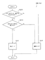
本実施形態の転写装置30C及び画像形成装置10Cは、図16のフローチャートのとおり、第1実施形態の画像形成装置10(図7参照)と比べると、判断ステップS220及びステップS240がない。そして、本実施形態の制御部60は、判断ステップS210で肯定判断をした場合、画像形成装置10Cに第1モードで画像形成動作を実行させる。別の見方をすると、本実施形態の転写装置30Cは、図16及び図17に示されるように、トナー像G1のみを形成するか否かに関わらず、ニップ部N2のニップ圧は、第1モードのニップ圧とされる。本実施形態の画像形成装置の画像形成動作は、第1実施形態の画像形成装置10の画像形成動作との関係において、上記の点以外は本実施形態の画像形成装置10の場合と同様とされている。
<Image Forming Operation of Image Forming Apparatus>
As shown in the flowchart of FIG. 16, the transfer device 30C and the image forming device 10C according to the present embodiment do not include the determination steps S220 and S240 as compared with the
<作用>
本実施形態の場合、前述のとおり、単色ユニット21Gはすべての単色ユニット21のうち転写ベルトTBの移動方向最下流に配置されている。そのため、第2実施形態の場合、トナー像G1のみを形成するか否かに関わらず、トナー像G1がニップ部N1を通過する回数は1回とされる。したがって、本実施形態の転写装置30Cは、ニップ部N2のニップ圧を第2モードのニップ圧とする場合に比べて、トナー像G1の飛散量が低減される。また、本実施形態の転写装置30Cは、トナー像G1のみを2次転写する場合のニップ部N2のニップ圧を第1モードのニップ圧とし、トナー像G1及びトナー像G2を2次転写する場合のニップ部N2のニップ圧を第2モードのニップ圧とする場合に比べて、両者の場合のトナーMTの飛散量の差が低減される。第2実施形態のその他の作用は、第1実施形態の第1〜第3の作用と同様である。
<Action>
In the case of the present embodiment, as described above, the
以上のとおり、本発明を特定の実施形態について詳細に説明したが、本発明は前述した実施形態に限定されるものではなく、本発明の技術的思想の範囲内にて他の実施形態が可能である。 As described above, the present invention has been described in detail with respect to specific embodiments. However, the present invention is not limited to the above-described embodiments, and other embodiments are possible within the scope of the technical idea of the present invention. It is.
例えば、第1実施形態の画像形成装置10は、制御部60が判断ステップS200、判断ステップS210、判断ステップS220を判断し、その判断に応じた画像形成動作(モード)を実行するとして説明した。しかしながら、上記各判断に応じたモードは一例であり、第1実施形態の画像形成装置10は、他のモードを有していてもよい。他の実施形態の画像形成装置10A、10B及び10Cの場合も同様である。
For example, in the
また、第1実施形態の画像形成装置10が用いるトナーMTは金色であるとして説明した。しかしながら、トナーMTが扁平な金属顔料を含む扁平トナーであれば、トナーMTは金色でなくてもよい。例えば、銀色等であってもよい。他の実施形態の画像形成装置10A、10B及び10Cの場合も同様である。
Further, the toner MT used by the
また、第1実施形態の画像形成装置10では、図1に示されるように、トナーMTを形成する単色ユニット21Gはトナー像形成部20のうち転写ベルトTBの移動方向最上流に配置されている。また、第2実施形態の10Cでは、図15に示されるように、トナーMTを形成する単色ユニット21Gはトナー像形成部20のうち転写ベルトTBの移動方向最下流に配置されている。しかしながら、トナー像形成部20に単色ユニット21Gが含まれていれば、単色ユニット21Gの配置は転写ベルトTBの移動方向最上流及び最下流でなくてもよい。例えば、単色ユニット21Gが一部の単色ユニット21(21Y、21M)よりも転写ベルトTBの移動方向下流側であって、残りの一部の単色ユニット21(21C、21K)よりも転写ベルトTBの移動方向上流側に配置されていてもよい。
Further, in the
また、第1実施形態の画像形成装置10では、BUR76に2次転写電圧が印加され、2次転写部70を構成する導電性ロール72が接地されているとして説明した。しかしながら、導電性ロール72に2次転写電圧が印加され、BUR76が接地されるようにしてもよい。他の実施形態の画像形成装置10A、10B及び10Cの場合も同様である。
Further, in the
また、第1実施形態の画像形成装置10では、BUR76が可動部78により上下方向に移動されることで、3つの動作位置に配置されるとして説明した。しかしながら、4つ以上の動作位置に配置されるようにしてもよい。他の実施形態の画像形成装置10A、10B及び10Cの場合も同様である。
Further, in the
また、第1実施形態の画像形成装置10では、BUR76が可動部78により上下方向に移動されることで、ニップ部N2のニップ圧を変更するとして説明した。しかしながら、BUR76は定められた位置に配置され、導電性ロール72を上下方向に移動可能とすることで、ニップ部N2のニップ圧を変更するようにしてもよい。他の実施形態の画像形成装置10A、10B及び10Cの場合も同様である。
In the
また、第1実施形態の画像形成装置10では、2次転写部70は、2次転写部70は、導電性ロール72と、テンションロール74と、導電性ベルトCBと、バックアップロール76と、可動部78と、を備えているとして説明した。しかしながら、2次転写部が転写ベルトTBに1次転写された各トナー像Gを、ニップ部N2で媒体Pに2次転写する機能を有すればよい。例えば、導電性ベルトCBを備えず、BUR76と導電性ロール72とで転写ベルトTBを挟んでニップ部N2を形成するようにしてもよい。
In the
また、第1実施形態の画像形成装置10では、2次転写ユニット34を構成する除去部90に第1除去部92及び第2除去部94が備えられているとして説明した。しかしながら、除去部90に軸周りに回転する回転体が備えられていれば、第1除去部92及び第2除去部94の何れか一方がなくてもよい。他の実施形態の画像形成装置10A、10B及び10Cの場合も同様である。
In the
また、第1実施形態の画像形成装置10では、2次転写ユニット34を構成する除去部90に第1除去部92及び第2除去部94が備えられているとして説明した。しかしながら、2次転写ユニット34は、第1除去部92及び第2除去部94に換えて、一例としてトナーTを搬送するオーガ等の回転体を備えていてもよい。つまり、2次転写ユニット34は、転写部に接触する回転体を備えずに、転写部に非接触の回転体を備えていてもよい。そして、転写部に非接触の回転体が回転することに伴い、当該回転体が転写部を振動させ、トナーMTを搬送される媒体Pの厚み方向に対して周期的に傾斜角度を変化させる原因となり得る。
In the
また、第1実施形態の画像形成装置10では、第1除去部92及び第2除去部94において、金属製シャフト92B、94Bに電圧を印加するとして説明した。しかしながら、導電性ブラシ92A、94Aに直接電圧を印加するように構成してもよい。
In the
また、第1実施形態の画像形成装置10では、基準比率R2の一例を1/2(50%)より大きいこととし、基準密度C2の一例を95%として説明した。しかしながら、これらは、前述のとおり、扁平な金属顔料MPの配向斑が視認され易い画像が形成されるかを官能評価により条件であることから、別の条件としてもよい。例えば、基準比率R2を一例として2/3より大きいこととし、基準密度C2を一例として85%としてもよい。他の実施形態の画像形成装置10A、10B及び10Cの場合も同様である。
In the
また、第1実施形態の画像形成装置10は、判断ステップS210に従いジョブデータに含まれるトナーMTのトナー像のデータが図9における領域A1に含まれる場合に特別モードで画像形成動作を実行するとして説明した。しかしながら、ジョブデータに含まれるトナーMTのトナー像のデータが図10における領域A2に含まれる場合に特別モードで画像形成動作を実行するように、判断ステップS210の条件として用いてもよい。
The
また、本発明の技術的範囲に含まれる第3比較形態の画像形成装置では、画像幅の比率R1及び基準比率R2を転写ベルトTBにおける形成可能幅に対する比率として説明した。しかしながら、形成可能幅は、画像幅の比率R1及び基準比率R2における基準の一例であり、画像幅の比率R1及び基準比率R2の基準を他の部材等の幅としてもよい。例えば、当該基準を、画像形成装置が搬送可能な媒体Pの最大幅、転写ベルトTBの幅、導電性ロール72の幅、BUR76の幅、感光体22の幅その他の幅としてもよい。
In the image forming apparatus according to the third comparative embodiment included in the technical scope of the present invention, the image width ratio R1 and the reference ratio R2 have been described as the ratio to the formable width on the transfer belt TB. However, the formable width is an example of a reference in the image width ratio R1 and the reference ratio R2, and the reference of the image width ratio R1 and the reference ratio R2 may be the width of another member or the like. For example, the reference may be the maximum width of the medium P that can be transported by the image forming apparatus, the width of the transfer belt TB, the width of the
また、第1実施形態の画像形成装置10では、実際に画像形成に用いる媒体Pの幅に応じて比率R1及び基準比率R2を変更するとして説明した。しかしながら、本発明は、画像形成装置が用いる媒体Pの幅が一定の幅とされており(一例としてA4サイズの媒体Pのみを同じ向きで搬送して画像形成を行う画像形成装置)についても適用される。この場合、実際に画像形成に用いる媒体Pの幅は一定であることから、比率R1及び基準比率R2は変更されない。他の実施形態の画像形成装置10A、10Bの場合も同様である。
In the
また、第1実施形態の画像形成装置10のトナー像形成部20は、単色ユニット21G、21Y、21M、21C、21Kで構成されているとして説明した(図1参照)。しかしながら、少なくともG(金)のトナー像G1を形成する単色ユニット21Gを備えており(別言すれば、1次転写ロール34Gを備えており)、少なくともG(金)のトナー像G1及び画像を形成することができれば、この画像形成装置は、本発明の技術的範囲に属する。そして、この画像形成装置を構成する転写装置(少なくとも、1次転写ロール34Gを備えている)は、本発明の技術的範囲に属する。
Further, the toner
また、第2実施形態の画像形成装置10Cのトナー像形成部20は、単色ユニット21G、21Y、21M、21C、21Kで構成されているとして説明した(図15参照)。しかしながら、少なくともG(金)のトナー像G1を形成する単色ユニット21Gを備えており(別言すれば、1次転写ロール34Gを備えており)、少なくともG(金)のトナー像G1及び画像を形成することができれば、この画像形成装置は、本発明の技術的範囲に属する。そして、この画像形成装置を構成する転写装置(少なくとも、1次転写ロール34Gを備えている)は、本発明の技術的範囲に属する。
10 画像形成装置
10A 画像形成装置
10B 画像形成装置
10C 画像形成装置
21 単色ユニット(形成部の一例)
21Y 単色ユニット(形成部の一例)
21M 単色ユニット(形成部の一例)
21C 単色ユニット(形成部の一例)
21K 単色ユニット(形成部の一例)
30 転写装置
30A 転写装置
30B 転写装置
30C 転写装置
34G 1次転写ロール(1次転写部の一例)
34Y 1次転写ロール(他の1次転写部の一例)
34M 1次転写ロール(他の1次転写部の一例)
34C 1次転写ロール(他の1次転写部の一例)
34K 1次転写ロール(他の1次転写部の一例)
70 2次転写部
C1 画像密度(予め定められた密度)
C2 基準密度
G1 トナー像(像の一例)
G2 トナー像(像の一例)
MP 金属顔料
MT 扁平トナー
N2 ニップ部
NT 非扁平トナー
R2 基準比率(予め定められた比率)
TB 転写ベルト(移動体の一例)
Further, the toner
DESCRIPTION OF
21Y single color unit (example of forming part)
21M single color unit (example of forming part)
21C single color unit (example of forming part)
21K single color unit (example of forming part)
30
34Y primary transfer roll (an example of another primary transfer section)
34M primary transfer roll (an example of another primary transfer unit)
34C primary transfer roll (an example of another primary transfer section)
34K primary transfer roll (an example of another primary transfer unit)
70 Secondary transfer portion C1 Image density (predetermined density)
C2 Reference density G1 Toner image (an example of an image)
G2 toner image (an example of an image)
MP metal pigment MT flat toner N2 nip NT non-flat toner R2 standard ratio (predetermined ratio)
TB transfer belt (an example of a moving body)
Claims (9)
扁平な金属顔料を含む扁平トナーで形成される像を前記移動体に転写する1次転写部と、
前記移動体とニップ部を形成し、前記ニップ部に搬送される媒体に前記移動体から前記像を転写し、前記像の画像幅が予め定められた幅よりも大きい又は前記像の画像密度が予め定められた密度よりも高い条件が満たされる場合に前記像を転写するときの前記ニップ部にかかる第1圧を、前記条件が満たされない場合に前記像を転写するときの前記ニップ部にかかる第2圧よりも高くする2次転写部と、
を備えた転写装置。 A moving object that moves,
A primary transfer unit that transfers an image formed of a flat toner containing a flat metal pigment to the moving body;
A nip portion is formed with the moving body, the image is transferred from the moving body to a medium conveyed to the nip portion, and an image width of the image is larger than a predetermined width or an image density of the image is A first pressure applied to the nip portion when the image is transferred when a condition higher than a predetermined density is satisfied, and a first pressure applied to the nip portion when the image is transferred when the condition is not satisfied. A secondary transfer portion that is higher than the second pressure;
A transfer device.
扁平な金属顔料を含む扁平トナーで形成される像を前記移動体に転写する1次転写部と、
前記移動体とニップ部を形成し、前記ニップ部に搬送される媒体に前記移動体から前記像を転写し、前記像の画像幅が予め定められた幅よりも大きく、かつ、前記像の画像密度が予め定められた密度よりも高い条件が満たれさる場合に前記像を転写するときの前記ニップ部にかかる第1圧を、前記条件が満たされない場合に前記像を転写するときの前記ニップ部にかかる第2圧よりも高くする2次転写部と、
を備えた転写装置。 A moving object that moves,
A primary transfer unit that transfers an image formed of a flat toner containing a flat metal pigment to the moving body;
A nip portion is formed with the moving body, the image is transferred from the moving body to a medium conveyed to the nip portion, and an image width of the image is larger than a predetermined width, and an image of the image The first pressure applied to the nip portion when the image is transferred when a condition where the density is higher than a predetermined density is satisfied, and the nip when the image is transferred when the condition is not satisfied. A secondary transfer portion that is higher than the second pressure applied to the portion;
A transfer device.
請求項2記載の転写装置。 The predetermined width is a width obtained by multiplying a predetermined ratio for each width of the medium.
The transfer device according to claim 2.
前記1次転写部は、前記他の1次転写部に対し前記移動体の移動方向上流側に配置されており、
前記2次転写部は、前記第1圧を前記第2圧よりも高くする場合、前記1次転写部が転写した像のみを媒体に転写するときの前記第1圧を、前記1次転写部及び前記他の1次転写部が転写した像を媒体に転写するときの前記第1圧よりも低くする、
請求項1〜3の何れか1項記載の転写装置。 Another primary transfer unit that transfers an image formed of non-flat toner to the moving body;
The primary transfer portion is disposed on the upstream side of the moving body with respect to the other primary transfer portion,
When the first pressure is higher than the second pressure, the secondary transfer unit applies the first pressure when transferring only the image transferred by the primary transfer unit to a medium. And lower than the first pressure when the image transferred by the other primary transfer portion is transferred to a medium,
The transfer device according to claim 1.
前記1次転写部は、前記他の1次転写部に対し前記移動体の移動方向下流側に配置されており、
前記2次転写部は、前記第1圧を前記第2圧よりも高くする場合、前記1次転写部が転写した像のみを媒体に転写するときの前記第1圧を、前記1次転写部及び前記他の1次転写部が転写した像を媒体に転写するときの前記第1圧と同等にする、
請求項1〜3の何れか1項記載の転写装置。 Another primary transfer unit that transfers an image formed of non-flat toner to the moving body;
The primary transfer portion is disposed on the downstream side of the moving body with respect to the other primary transfer portion,
When the first pressure is higher than the second pressure, the secondary transfer unit applies the first pressure when transferring only the image transferred by the primary transfer unit to a medium. And equivalent to the first pressure when the image transferred by the other primary transfer portion is transferred to a medium,
The transfer device according to claim 1.
扁平な金属顔料を含む扁平トナーで形成される像を前記移動体に転写する1次転写部と、
非扁平トナーで形成される像を前記移動体に転写する他の1次転写部と、
前記移動体とニップ部を形成し、前記ニップ部に搬送される媒体に前記移動体から前記像を転写し、前記1次転写部が転写した像を媒体に転写する場合の前記ニップ部の第1圧を、前記他の1次転写部が転写した像のみを転写する場合の前記ニップ部の第2圧よりも高くする2次転写部と、
を備えた転写装置。 A moving object that moves,
A primary transfer unit that transfers an image formed of a flat toner containing a flat metal pigment to the moving body;
Another primary transfer portion for transferring an image formed of non-flat toner to the moving body;
Forming a nip portion with the moving body, transferring the image from the moving body to a medium conveyed to the nip portion, and transferring the image transferred by the primary transfer portion to the medium; A secondary transfer portion that makes the first pressure higher than the second pressure of the nip portion when transferring only the image transferred by the other primary transfer portion;
A transfer device.
前記2次転写部は、前記第1圧を前記第2圧よりも高くする場合、前記1次転写部が転写した像のみを媒体に転写するときの前記第1圧を、前記1次転写部及び前記他の1次転写部が転写した像を媒体に転写するときの前記第1圧よりも低くする、
請求項6記載の転写装置。 The primary transfer portion is disposed on the upstream side of the moving body with respect to the other primary transfer portion,
When the first pressure is higher than the second pressure, the secondary transfer unit applies the first pressure when transferring only the image transferred by the primary transfer unit to a medium. And lower than the first pressure when the image transferred by the other primary transfer portion is transferred to a medium,
The transfer device according to claim 6.
前記2次転写部は、前記第1圧を前記第2圧よりも高くする場合、前記1次転写部が転写した像のみを媒体に転写するときの前記第1圧を、前記1次転写部及び前記他の1次転写部が転写した像を媒体に転写するときの前記第1圧と同等にする、
請求項6記載の転写装置。 The primary transfer portion is disposed on the downstream side of the moving body with respect to the other primary transfer portion,
When the first pressure is higher than the second pressure, the secondary transfer unit applies the first pressure when transferring only the image transferred by the primary transfer unit to a medium. And equivalent to the first pressure when the image transferred by the other primary transfer portion is transferred to a medium,
The transfer device according to claim 6.
前記移動体に転写される像を形成する形成部と、
を備えた画像形成装置。 A transfer device according to any one of claims 1 to 8,
A forming part for forming an image to be transferred to the moving body;
An image forming apparatus.
Priority Applications (1)
| Application Number | Priority Date | Filing Date | Title |
|---|---|---|---|
| JP2015033092A JP6428362B2 (en) | 2015-02-23 | 2015-02-23 | Transfer device and image forming apparatus |
Applications Claiming Priority (1)
| Application Number | Priority Date | Filing Date | Title |
|---|---|---|---|
| JP2015033092A JP6428362B2 (en) | 2015-02-23 | 2015-02-23 | Transfer device and image forming apparatus |
Publications (2)
| Publication Number | Publication Date |
|---|---|
| JP2016156879A JP2016156879A (en) | 2016-09-01 |
| JP6428362B2 true JP6428362B2 (en) | 2018-11-28 |
Family
ID=56825778
Family Applications (1)
| Application Number | Title | Priority Date | Filing Date |
|---|---|---|---|
| JP2015033092A Expired - Fee Related JP6428362B2 (en) | 2015-02-23 | 2015-02-23 | Transfer device and image forming apparatus |
Country Status (1)
| Country | Link |
|---|---|
| JP (1) | JP6428362B2 (en) |
Families Citing this family (1)
| Publication number | Priority date | Publication date | Assignee | Title |
|---|---|---|---|---|
| JP2019184642A (en) * | 2018-04-02 | 2019-10-24 | 富士ゼロックス株式会社 | Image forming apparatus |
Family Cites Families (5)
| Publication number | Priority date | Publication date | Assignee | Title |
|---|---|---|---|---|
| JP2002304001A (en) * | 2001-04-05 | 2002-10-18 | Konica Corp | Image forming method |
| KR100449986B1 (en) * | 2002-06-07 | 2004-09-24 | 삼성전자주식회사 | a wet electrophotograph type printer having subsidiary intermediate transfer part for improving the transfer efficiency |
| JP6019865B2 (en) * | 2012-07-19 | 2016-11-02 | 富士ゼロックス株式会社 | Toner set, image forming apparatus, and image forming method |
| JP5954018B2 (en) * | 2012-07-24 | 2016-07-20 | 富士ゼロックス株式会社 | Image forming apparatus |
| JP5765454B2 (en) * | 2013-05-16 | 2015-08-19 | 富士ゼロックス株式会社 | Image forming apparatus |
-
2015
- 2015-02-23 JP JP2015033092A patent/JP6428362B2/en not_active Expired - Fee Related
Also Published As
| Publication number | Publication date |
|---|---|
| JP2016156879A (en) | 2016-09-01 |
Similar Documents
| Publication | Publication Date | Title |
|---|---|---|
| CN103576514B (en) | Image forming apparatus, and image forming method | |
| JP6108153B2 (en) | Fixing apparatus, image forming apparatus, and image forming method | |
| JP5358558B2 (en) | Image forming apparatus | |
| JP6926561B2 (en) | Image forming device | |
| JP6428362B2 (en) | Transfer device and image forming apparatus | |
| JP6634759B2 (en) | Transfer device and image forming device | |
| JP5858184B1 (en) | Transfer device and image forming apparatus | |
| JP2009003275A (en) | Image forming apparatus | |
| JP4293125B2 (en) | Image forming apparatus | |
| JP6544980B2 (en) | Image forming device | |
| JP5822037B1 (en) | Image forming apparatus | |
| US9383689B1 (en) | Image forming apparatus that transfers a first image formed using a toner containing a pigment other than a flat pigment and that transfers a second image formed using a toner containing a flat pigment | |
| JP5987864B2 (en) | Image forming apparatus | |
| JP6417986B2 (en) | Image forming apparatus | |
| US20160077467A1 (en) | Image forming apparatus and image forming method | |
| JP2017156709A (en) | Image forming apparatus | |
| CN105892251B (en) | Transfer device and image forming apparatus | |
| JP2017026650A (en) | Image forming apparatus | |
| US9291959B1 (en) | Image forming apparatus and image forming method | |
| JP5213753B2 (en) | Image forming apparatus | |
| JP6007759B2 (en) | Image forming apparatus and rotation control method | |
| US9417582B1 (en) | Image forming apparatus including a controller that controls superposition of a correction toner image | |
| JP4773843B2 (en) | Image forming apparatus | |
| JP2009300858A (en) | Pressure contact drive device | |
| JP2018097170A (en) | Image formation apparatus |
Legal Events
| Date | Code | Title | Description |
|---|---|---|---|
| A621 | Written request for application examination |
Free format text: JAPANESE INTERMEDIATE CODE: A621 Effective date: 20180116 |
|
| A977 | Report on retrieval |
Free format text: JAPANESE INTERMEDIATE CODE: A971007 Effective date: 20180905 |
|
| TRDD | Decision of grant or rejection written | ||
| A01 | Written decision to grant a patent or to grant a registration (utility model) |
Free format text: JAPANESE INTERMEDIATE CODE: A01 Effective date: 20181002 |
|
| A61 | First payment of annual fees (during grant procedure) |
Free format text: JAPANESE INTERMEDIATE CODE: A61 Effective date: 20181015 |
|
| R150 | Certificate of patent or registration of utility model |
Ref document number: 6428362 Country of ref document: JP Free format text: JAPANESE INTERMEDIATE CODE: R150 |
|
| S533 | Written request for registration of change of name |
Free format text: JAPANESE INTERMEDIATE CODE: R313533 |
|
| R350 | Written notification of registration of transfer |
Free format text: JAPANESE INTERMEDIATE CODE: R350 |
|
| LAPS | Cancellation because of no payment of annual fees |