JP6426719B2 - Reinforcement package - Google Patents
Reinforcement package Download PDFInfo
- Publication number
- JP6426719B2 JP6426719B2 JP2016517471A JP2016517471A JP6426719B2 JP 6426719 B2 JP6426719 B2 JP 6426719B2 JP 2016517471 A JP2016517471 A JP 2016517471A JP 2016517471 A JP2016517471 A JP 2016517471A JP 6426719 B2 JP6426719 B2 JP 6426719B2
- Authority
- JP
- Japan
- Prior art keywords
- panel
- fold line
- bag
- carton
- partially
- Prior art date
- Legal status (The legal status is an assumption and is not a legal conclusion. Google has not performed a legal analysis and makes no representation as to the accuracy of the status listed.)
- Active
Links
- 230000002787 reinforcement Effects 0.000 title claims 2
- 238000004026 adhesive bonding Methods 0.000 claims description 18
- 230000003014 reinforcing effect Effects 0.000 claims description 16
- 238000000034 method Methods 0.000 claims description 13
- 238000005452 bending Methods 0.000 claims description 9
- 230000002093 peripheral effect Effects 0.000 claims description 4
- 238000007789 sealing Methods 0.000 claims description 3
- 238000005728 strengthening Methods 0.000 claims 1
- 239000000463 material Substances 0.000 description 29
- 239000000853 adhesive Substances 0.000 description 8
- 230000001070 adhesive effect Effects 0.000 description 8
- 239000011087 paperboard Substances 0.000 description 7
- 230000004048 modification Effects 0.000 description 5
- 238000012986 modification Methods 0.000 description 5
- 230000008901 benefit Effects 0.000 description 4
- 230000015572 biosynthetic process Effects 0.000 description 4
- 239000004927 clay Substances 0.000 description 4
- 239000003292 glue Substances 0.000 description 4
- 230000008569 process Effects 0.000 description 4
- 239000000123 paper Substances 0.000 description 3
- 239000004033 plastic Substances 0.000 description 3
- 229920003023 plastic Polymers 0.000 description 3
- -1 polyethylene Polymers 0.000 description 3
- QAOWNCQODCNURD-UHFFFAOYSA-L Sulfate Chemical compound [O-]S([O-])(=O)=O QAOWNCQODCNURD-UHFFFAOYSA-L 0.000 description 2
- 239000011111 cardboard Substances 0.000 description 2
- 238000010411 cooking Methods 0.000 description 2
- 235000013305 food Nutrition 0.000 description 2
- 238000010438 heat treatment Methods 0.000 description 2
- 239000002655 kraft paper Substances 0.000 description 2
- 239000007788 liquid Substances 0.000 description 2
- 239000007787 solid Substances 0.000 description 2
- XLYOFNOQVPJJNP-UHFFFAOYSA-N water Substances O XLYOFNOQVPJJNP-UHFFFAOYSA-N 0.000 description 2
- 102100036876 Cyclin-K Human genes 0.000 description 1
- 101000713127 Homo sapiens Cyclin-K Proteins 0.000 description 1
- 239000004698 Polyethylene Substances 0.000 description 1
- 239000004743 Polypropylene Substances 0.000 description 1
- 239000004793 Polystyrene Substances 0.000 description 1
- 235000002017 Zea mays subsp mays Nutrition 0.000 description 1
- 241000482268 Zea mays subsp. mays Species 0.000 description 1
- 230000009471 action Effects 0.000 description 1
- 230000004888 barrier function Effects 0.000 description 1
- 230000000295 complement effect Effects 0.000 description 1
- 239000012530 fluid Substances 0.000 description 1
- 230000008520 organization Effects 0.000 description 1
- 230000000149 penetrating effect Effects 0.000 description 1
- 229920000573 polyethylene Polymers 0.000 description 1
- 239000005020 polyethylene terephthalate Substances 0.000 description 1
- 229920000139 polyethylene terephthalate Polymers 0.000 description 1
- 229920001155 polypropylene Polymers 0.000 description 1
- 229920002223 polystyrene Polymers 0.000 description 1
- 239000004800 polyvinyl chloride Substances 0.000 description 1
- 229920000915 polyvinyl chloride Polymers 0.000 description 1
- 239000011099 solid bleached board Substances 0.000 description 1
- 230000003313 weakening effect Effects 0.000 description 1
Images


Classifications
-
- B—PERFORMING OPERATIONS; TRANSPORTING
- B65—CONVEYING; PACKING; STORING; HANDLING THIN OR FILAMENTARY MATERIAL
- B65D—CONTAINERS FOR STORAGE OR TRANSPORT OF ARTICLES OR MATERIALS, e.g. BAGS, BARRELS, BOTTLES, BOXES, CANS, CARTONS, CRATES, DRUMS, JARS, TANKS, HOPPERS, FORWARDING CONTAINERS; ACCESSORIES, CLOSURES, OR FITTINGS THEREFOR; PACKAGING ELEMENTS; PACKAGES
- B65D5/00—Rigid or semi-rigid containers of polygonal cross-section, e.g. boxes, cartons or trays, formed by folding or erecting one or more blanks made of paper
- B65D5/42—Details of containers or of foldable or erectable container blanks
- B65D5/56—Linings or internal coatings, e.g. pre-formed trays provided with a blow- or thermoformed layer
- B65D5/60—Loose, or loosely attached, linings
- B65D5/603—Flexible linings loosely glued to the wall of the container
- B65D5/606—Bags or bag-like tubes loosely glued to the wall of a "tubular" container
-
- B—PERFORMING OPERATIONS; TRANSPORTING
- B65—CONVEYING; PACKING; STORING; HANDLING THIN OR FILAMENTARY MATERIAL
- B65D—CONTAINERS FOR STORAGE OR TRANSPORT OF ARTICLES OR MATERIALS, e.g. BAGS, BARRELS, BOTTLES, BOXES, CANS, CARTONS, CRATES, DRUMS, JARS, TANKS, HOPPERS, FORWARDING CONTAINERS; ACCESSORIES, CLOSURES, OR FITTINGS THEREFOR; PACKAGING ELEMENTS; PACKAGES
- B65D5/00—Rigid or semi-rigid containers of polygonal cross-section, e.g. boxes, cartons or trays, formed by folding or erecting one or more blanks made of paper
- B65D5/02—Rigid or semi-rigid containers of polygonal cross-section, e.g. boxes, cartons or trays, formed by folding or erecting one or more blanks made of paper by folding or erecting a single blank to form a tubular body with or without subsequent folding operations, or the addition of separate elements, to close the ends of the body
- B65D5/10—Rigid or semi-rigid containers of polygonal cross-section, e.g. boxes, cartons or trays, formed by folding or erecting one or more blanks made of paper by folding or erecting a single blank to form a tubular body with or without subsequent folding operations, or the addition of separate elements, to close the ends of the body with end closures formed by inward-folding of self-locking flaps hinged to tubular body
- B65D5/103—Rigid or semi-rigid containers of polygonal cross-section, e.g. boxes, cartons or trays, formed by folding or erecting one or more blanks made of paper by folding or erecting a single blank to form a tubular body with or without subsequent folding operations, or the addition of separate elements, to close the ends of the body with end closures formed by inward-folding of self-locking flaps hinged to tubular body one of the self-locking flaps having a tongue engaging into an opening of an opposite flap
-
- B—PERFORMING OPERATIONS; TRANSPORTING
- B65—CONVEYING; PACKING; STORING; HANDLING THIN OR FILAMENTARY MATERIAL
- B65D—CONTAINERS FOR STORAGE OR TRANSPORT OF ARTICLES OR MATERIALS, e.g. BAGS, BARRELS, BOTTLES, BOXES, CANS, CARTONS, CRATES, DRUMS, JARS, TANKS, HOPPERS, FORWARDING CONTAINERS; ACCESSORIES, CLOSURES, OR FITTINGS THEREFOR; PACKAGING ELEMENTS; PACKAGES
- B65D5/00—Rigid or semi-rigid containers of polygonal cross-section, e.g. boxes, cartons or trays, formed by folding or erecting one or more blanks made of paper
- B65D5/36—Rigid or semi-rigid containers of polygonal cross-section, e.g. boxes, cartons or trays, formed by folding or erecting one or more blanks made of paper specially constructed to allow collapsing and re-erecting without disengagement of side or bottom connections
- B65D5/3607—Rigid or semi-rigid containers of polygonal cross-section, e.g. boxes, cartons or trays, formed by folding or erecting one or more blanks made of paper specially constructed to allow collapsing and re-erecting without disengagement of side or bottom connections formed by folding or erecting a single blank
- B65D5/3614—Rigid or semi-rigid containers of polygonal cross-section, e.g. boxes, cartons or trays, formed by folding or erecting one or more blanks made of paper specially constructed to allow collapsing and re-erecting without disengagement of side or bottom connections formed by folding or erecting a single blank to form a tubular body, at least one of the ends of the body remaining connected
- B65D5/3628—Rigid or semi-rigid containers of polygonal cross-section, e.g. boxes, cartons or trays, formed by folding or erecting one or more blanks made of paper specially constructed to allow collapsing and re-erecting without disengagement of side or bottom connections formed by folding or erecting a single blank to form a tubular body, at least one of the ends of the body remaining connected collapsed along median lines of two opposite sides of the rectangular tubular body
-
- B—PERFORMING OPERATIONS; TRANSPORTING
- B31—MAKING ARTICLES OF PAPER, CARDBOARD OR MATERIAL WORKED IN A MANNER ANALOGOUS TO PAPER; WORKING PAPER, CARDBOARD OR MATERIAL WORKED IN A MANNER ANALOGOUS TO PAPER
- B31B—MAKING CONTAINERS OF PAPER, CARDBOARD OR MATERIAL WORKED IN A MANNER ANALOGOUS TO PAPER
- B31B2120/00—Construction of rigid or semi-rigid containers
- B31B2120/20—Construction of rigid or semi-rigid containers provided with two or more compartments
- B31B2120/25—Construction of rigid or semi-rigid containers provided with two or more compartments formed by partitions or like inserts not integral with walls
Landscapes
- Engineering & Computer Science (AREA)
- Mechanical Engineering (AREA)
- Packages (AREA)
- Cartons (AREA)
- Bag Frames (AREA)
- Package Specialized In Special Use (AREA)
Description
[関連出願の相互参照]
本願は、2013年9月25日に出願された米国仮特許出願第61/960712号の利益を主張する。
[Cross-reference to related applications]
This application claims the benefit of US Provisional Patent Application No. 61 / 960,712, filed Sep. 25, 2013.
[参照による援用]
2013年9月25日に出願された米国仮特許出願第61/960712号の開示は、その全体が本明細書に提示されているかのように、全ての目的で引用することにより本明細書の一部をなす。
[Included by reference]
The disclosure of US Provisional Patent Application No. 61 / 960,712, filed September 25, 2013, is hereby incorporated by reference for all purposes as if provided in its entirety herein. Make a part.
本開示は、包括的には、製品を保持するパッケージに関する。本開示は、より詳細には、袋を支持する強化用カートンを備えるパッケージに関する。 The present disclosure relates generally to a package for holding a product. The present disclosure relates more particularly to a package comprising a reinforcing carton supporting a bag.
1つの態様において、本開示は、包括的には、製品を保持する強化パッケージに関する。該強化パッケージは、複数のパネルを有するカートンを備えることができ、該複数のパネルは、該カートンの内部の回りに少なくとも部分的に延びる。該複数のパネルは、フロントパネルと、該フロントパネルに折り曲げ可能につながっている第1のサイドパネルと、前記フロントパネルに折り曲げ可能につながっている第2のサイドパネルと、前記第1のサイドパネル及び前記第2のサイドパネルのうちの少なくとも一方に折り曲げ可能につながっている少なくとも1つのバックパネルと、前記フロントパネル及び前記バックパネルのうちの少なくとも一方に折り曲げ可能につながっている少なくとも1つのボトムパネルとを含むことができる。袋が、少なくとも部分的に開放した端部と、少なくとも部分的に閉鎖した端部と、製品を保持する内部空間とを有することができる。該袋は、前記カートンの前記内部に少なくとも部分的に収めることができる。前記カートンは、前記袋の前記内部空間が少なくとも部分的に縮小する非起立位置と、前記袋の前記内部空間が拡大する起立位置とに配置可能である。前記カートンは、前記袋を前記起立位置に支持するように構成することができる。 In one aspect, the present disclosure relates generally to a reinforced package for holding a product. The reinforced package may comprise a carton having a plurality of panels, the plurality of panels extending at least partially around an interior of the carton. The plurality of panels are a front panel, a first side panel foldably connected to the front panel, a second side panel foldably connected to the front panel, and the first side panel And at least one back panel foldably connected to at least one of the second side panels, and at least one bottom panel foldably connected to at least one of the front panel and the back panel And can be included. The bag can have an at least partially open end, an at least partially closed end, and an interior space for holding the product. The bag can be at least partially contained within the interior of the carton. The carton may be arranged in a non-upstanding position in which the internal space of the bag at least partially reduces and in an upright position in which the internal space of the bag is enlarged. The carton may be configured to support the bag in the upright position.
別の態様において、本開示は、包括的には、製品を保持する強化用カートンに関する。該強化用カートンは、該カートンの内部の回りに少なくとも部分的に延びる複数のパネルを含むことができる。該複数のパネルは、フロントパネルと、該フロントパネルに折り曲げ可能につながっている第1のサイドパネルと、前記フロントパネルに折り曲げ可能につながっている第2のサイドパネルと、前記第1のサイドパネル及び前記第2のサイドパネルのうちの少なくとも一方に折り曲げ可能につながっている少なくとも1つのバックパネルと、前記フロントパネル及び前記バックパネルのうちの少なくとも一方に折り曲げ可能につながっている少なくとも1つのボトムパネルとを含むことができる。前記複数のパネルのうちの少なくとも1つのパネルには、係止構成部が存在することができる。該係止構成部は、該強化用カートンを起立位置に少なくとも部分的に保持するように機能するとともに、該強化用カートンの非起立位置に向かって前記複数のパネルが少なくとも部分的に折り畳まれることを可能にすることができる。 In another aspect, the present disclosure relates generally to a reinforcing carton for holding a product. The reinforcing carton can include a plurality of panels extending at least partially around the interior of the carton. The plurality of panels are a front panel, a first side panel foldably connected to the front panel, a second side panel foldably connected to the front panel, and the first side panel And at least one back panel foldably connected to at least one of the second side panels, and at least one bottom panel foldably connected to at least one of the front panel and the back panel And can be included. A locking arrangement may be present on at least one of the plurality of panels. The locking arrangement functions to at least partially hold the reinforcing carton in the upright position and at least partially fold the plurality of panels towards the non-standing position of the reinforcing carton. Can be made possible.
別の態様において、本開示は、包括的には、製品を保持する強化パッケージを形成するカートンブランクと袋との組合せ体に関する。該カートンブランクは複数のパネルを備え、該複数のパネルは、フロントパネルと、該フロントパネルに折り曲げ可能につながっている第1のサイドパネルと、前記フロントパネルに折り曲げ可能につながっている第2のサイドパネルと、前記第1のサイドパネル及び前記第2のサイドパネルのうちの少なくとも一方に折り曲げ可能につながっている少なくとも1つのバックパネルと、前記フロントパネル及び前記バックパネルのうちの少なくとも一方に折り曲げ可能につながっている少なくとも1つのボトムパネルとを含む。袋は、少なくとも部分的に開放した端部と、少なくとも部分的に閉鎖した端部と、製品を保持する内部空間とを有することができる。該袋は、前記カートンブランクに少なくとも部分的に貼付することができる。前記カートンブランク及び前記袋から形成された前記強化パッケージは、前記袋の前記内部空間が少なくとも部分的に縮小する非起立位置と、前記袋の前記内部空間が拡大する起立位置とに配置可能である。 In another aspect, the present disclosure relates generally to a carton blank and bag combination that forms a reinforced package for holding a product. The carton blank comprises a plurality of panels, the plurality of panels comprising a front panel, a first side panel foldably connected to the front panel, and a second foldably connected to the front panel A side panel, at least one back panel foldably connected to at least one of the first side panel and the second side panel, and at least one of the front panel and the back panel And at least one bottom panel, possibly connected. The bag can have an at least partially open end, an at least partially closed end, and an interior space for holding the product. The bag can be at least partially affixed to the carton blank. The carton blank and the reinforced package formed from the bag may be arranged in a non-upstanding position in which the internal space of the bag at least partially reduces and in an upright position in which the internal space of the bag is enlarged .
別の態様において、本開示は、包括的には、製品を保持する強化パッケージを形成する方法に関する。該方法は、複数のパネルを有するカートンブランクを得ることであって、該複数のパネルは、フロントパネルと、該フロントパネルに折り曲げ可能につながっている第1のサイドパネルと、前記フロントパネルに折り曲げ可能につながっている第2のサイドパネルと、前記第1のサイドパネル及び前記第2のサイドパネルのうちの少なくとも一方に折り曲げ可能につながっている少なくとも1つのバックパネルと、前記フロントパネル及び前記バックパネルのうちの少なくとも一方に折り曲げ可能につながっている少なくとも1つのボトムパネルとを含むことを含むことができる。また、該方法は、ライナーブランクを得ることと、少なくとも部分的に開放した端部と、少なくとも部分的に閉鎖した端部と、製品を保持する内部空間とを有するように、前記ライナーブランクから袋を形成することと、前記袋の少なくとも一部を前記カートンブランクの前記フロントパネル及び前記バックパネルのうちの少なくとも一方に貼付することと、前記複数のパネルによって少なくとも部分的に画定されるカートンの内部を形成することとを含むことができる。前記カートンの前記内部を形成することは、開端スリーブを形成することを含むことができる。前記カートンは、前記袋の前記内部空間が少なくとも部分的に縮小する非起立位置と、前記袋の前記内部空間が拡大する起立位置とに配置可能とすることができる。前記カートンは、前記袋を前記起立位置に支持するように構成することができる。 In another aspect, the present disclosure relates generally to a method of forming a reinforced package for holding a product. The method is to obtain a carton blank having a plurality of panels, the plurality of panels being folded to a front panel, a first side panel foldably connected to the front panel, and the front panel. A second side panel possibly connected, at least one back panel foldably connected to at least one of the first side panel and the second side panel, the front panel and the back And D. at least one bottom panel foldably connected to at least one of the panels. Also, the method comprises: obtaining the liner blank, the at least partially open end, the at least partially closed end, and the bag from the liner blank so as to have an interior space for holding the product. Forming at least a portion of the bag on at least one of the front panel and the back panel of the carton blank; and an interior of the carton defined at least partially by the plurality of panels. And B. forming. Forming the interior of the carton can include forming an open end sleeve. The carton may be arrangeable in a non-upstanding position in which the internal space of the bag at least partially reduces and in an upright position in which the internal space of the bag is enlarged. The carton may be configured to support the bag in the upright position.
当業者は、添付図面を参照して実施形態の以下の詳細な説明を読むことによって、上記の利点、並びに種々の更なる実施形態の他の利点及び利益を理解するであろう。個々に、また様々な組合せで与えられる上述の態様が本開示の範囲内にある。 Those skilled in the art will appreciate the above advantages as well as other advantages and benefits of various additional embodiments by reading the following detailed description of the embodiments with reference to the accompanying drawings. The aspects described above, given individually and in various combinations, are within the scope of the present disclosure.
慣例によれば、以下で説明する図面の種々の特徴は、必ずしも一定の縮尺比で描かれているとは限らない。図面における種々の特徴及び要素の寸法は、本開示の実施形態をより明確に示すために拡大又は縮小されている場合がある。 By convention, the various features of the drawings described below are not necessarily drawn to scale. Dimensions of various features and elements in the drawings may be expanded or reduced to more clearly illustrate the embodiments of the present disclosure.
対応する部分は、図面を通して対応する参照符号によって示されている。 Corresponding parts are indicated by corresponding reference numerals throughout the drawings.
本開示は、包括的には、食品又は他の物品等の製品又は物品を保持するカートン及びパッケージに関する。本開示に係るパッケージは、いかなる形状の物品にも対応することができる。本開示の範囲を限定するためではなく例示のために、「下側」、「ボトム」、「上側」、「トップ」、「フロント」、及び「バック」という用語は、起立したカートンに関して規定される配置構成を示す。 The present disclosure relates generally to cartons and packages for holding products or articles such as food or other articles. The package according to the present disclosure can correspond to articles of any shape. For purposes of illustration and not to limit the scope of the present disclosure, the terms "lower", "bottom", "upper", "top", "front", and "back" are defined with respect to an erected carton Show the layout configuration.
図1は、本開示の一実施形態に係るカートンブランク3の内面1の平面図である。カートンブランク3は、強化パッケージ200(図14)の袋6すなわちライナー材を保持する強化用カートン5(図5)を形成するものである。カートンブランク3は、横軸L1及び長手方向軸L2を有する。図示の実施形態では、カートンブランク3は、第1の折り曲げ線33において第1のサイドパネル28に折り曲げ可能につながっているフロントパネル21と、第2の折り曲げ線37において第1のサイドパネル28に折り曲げ可能につながっているバックパネル23と、第3の折り曲げ線40においてフロントパネル21に折り曲げ可能につながっている第2のサイドパネル29とを有する。図1に示すように、貼付用フラップ25が、第4の折り曲げ線43において第2のサイドパネル29に折り曲げ可能につながっている。
FIG. 1 is a plan view of the
図1に示すように、第1のサイドパネル28は、横折り曲げ線26に沿って互いに折り曲げ可能につながっている2つの個々のパネル部分28a、28bを含む。同様に、第2のサイドパネル29は、横折り曲げ線27に沿って互いに折り曲げ可能につながっている2つの個々のパネル部分29a、29bを含む。
As shown in FIG. 1, the
図示の実施形態では、第1の折り曲げ線33は、頂点30aから延びる2つの斜め折り曲げ線セグメント34、35に分割されている。第2の折り曲げ線37は、頂点30bから延びる2つの斜め折り曲げ線セグメント38、39に分割されている。第3の折り曲げ線40は、頂点31aから延びる2つの斜め折り曲げ線セグメント41、42に分割されている。第4の折り曲げ線43は、頂点31bから延びる2つの斜め折り曲げ線セグメント44、45に分割されている。折り曲げ線33、37は、頂点30a、30bが、斜めの折り曲げ線セグメント34、35、38、39の両端部よりも横折り曲げ線26から遠く離間する(例えば、パネル部分28a、28b及び第1のサイドパネル28が頂点30a、30b間又は頂点30a、30b近傍で最も幅広である)ように、横折り曲げ線26から離間することができる。同様に、折り曲げ線40、43は、頂点31a、31bが、斜めの折り曲げ線セグメント41、42、44、48の両端部よりも横折り曲げ線27から遠く離間する(例えば、パネル部分29a、29b及び第1のサイドパネル29が頂点31a、31b間又は頂点31a、31b近傍で最も幅広である)ように、横折り曲げ線27から離間している。折り曲げ線33、37、40、43は、本開示から逸脱することなく、省略することもできるし、別様の構成、形状、配置、及び/又は形態とすることもできる。例えば、折り曲げ線は、図示のように分割された折り曲げ線ではなく弧状の折り曲げ線とすることができる。
In the illustrated embodiment, the
図1に示すように、ブランク3は、長手方向折り曲げ線71においてバックパネル23に折り曲げ可能につながっている第1のボトムパネル51と、長手方向折り曲げ線72においてフロントパネル21に折り曲げ可能につながっている第2のボトムパネル52とを更に有することができる。図示のように、ボトム端部フラップ53は、折り曲げ線57において第2のボトムパネル52に折り曲げ可能につながっている。係止タブ55が、第2のボトムパネル52から延びており、切れ目58に沿ってボトム端部フラップ53から分離可能である。さらに、相補的な係止ノッチ又は係止リセス54が第1のボトムパネル51に形成されており、係止タブ55に係合する第1のボトムパネル51の縁を画定する。係止ノッチ54は、係止タブ55に係合するサイズ又は寸法である。
As shown in FIG. 1, the blank 3 is foldably connected to the first
図示の実施形態では、ブランク3は、バックパネル23及びフロントパネル21に接着用領域60を含み、該接着用領域60は接着剤を受容し袋6の外面に固定的に取り付けられる。さらに、ブランク3は、貼付用フラップ25に、接着剤を受けるとともにバックパネル23の内面に固定的に取り付けられる接着用領域61を有することができる。接着用領域60、61は、本開示から逸脱することなく、省略することもできるし、別様の構成、形状、配置、及び/又は形態とすることもできる。
In the illustrated embodiment, the blank 3 comprises an
図1に示すように、カートンブランク3は、概ね長手方向L2に延びる第1の縁70(例えば自由縁)を有する。ブランク3は、第1の縁70の反対側に構成された斜縁73、74、75、及び76(例えば自由縁)を更に有する。それに応じて、縁73、74、75、76は、それぞれのパネル部分28b、28a、29a、29bの下側自由縁を形成する。縁70、73、74、75、76は、本開示から逸脱することなく、省略することもできるし、別様の構成、形状、配置、及び/又は形態とすることもできる。
As shown in FIG. 1, the carton blank 3 has a first edge 70 (e.g., a free edge) extending generally in the longitudinal direction L2. The blank 3 further has beveled
図示の実施形態では、カートンブランク3及びカートン5は、本開示から逸脱することなく、板紙、クレーコートされた板紙、同質漂白板(SBB:solid bleached board)板紙、同質漂白硫酸塩(SBS:solid bleached sulphate)板紙、クラフトライナー(正:liner)板紙、又は任意の他の好適な材料等の比較的硬質の任意の材料を含むことができる。代替的な実施形態において、カートンブランク3は、別様の形状とすることができ、代替的なパネル構成、フラップ構成、折り曲げ線構成、及び/又はパネル部分構成を有することができる。
In the illustrated embodiment, the carton blank 3 and the
図2を参照すると、インサートブランク103すなわちライナー材部分の内面101の平面図が示されている。インサートブランク103は、強化パッケージ200(図12)の袋6(図6)を形成するものである。図2に示すように、ライナーブランク103の横軸L1及び長手方向軸L2は、ライナーブランク103の横軸L1及び長手方向軸L2が図1に定められているカートンブランク3のそれぞれの横軸L1及び長手方向軸L2に一致するように向き付けられる。ライナーブランク103すなわちライナー材は、形成された袋6が液体を保持することができるように、ほぼ不透過性の材料又は材料層で形成することができる。ライナーブランク103は、比較的軟質かつ比較的流体浸透性である任意の好適な材料を含むことができる。ライナーブランク103は、本開示から逸脱することなく、ポリエチレン、ポリプロピレン、ポリエチレンテレフタレート、ポリスチレン、ポリ塩化ビニル等のプラスチック、又は任意の他の好適な材料を含むことができる。代替的には、ライナーブランク103は、本開示から逸脱することなく流体透過性材料を含むことができる。
Referring to FIG. 2, a plan view of the
図2に示すように、ライナーブランク103は、それぞれ折り曲げ線109、110においてガセットパネル107、108に折り曲げ可能につながっている側壁105、106を有することができる。ガセットパネル107、108は、折り曲げ線113において互いに折り曲げ可能につながっていることができる。ライナーブランク103は、ブランクのそれぞれの周囲領域に沿って延び、それぞれの横に延びる縁117、118とそれぞれの線119、120との間に少なくとも部分的に画定される、糊付け用エリア(glue areas:糊代)115、116を有することができる。1つの実施形態において、線119、120は、糊付け用エリア115、116の内縁を概略的に示しているだけである。代替的な一実施形態において、線119、120は、ライナーブランク103に描画及び/又は形成される。例えば、ガイド線をライナーブランク103に描画することができ、及び/又は、折り目をライナーブランク103に形成することができる。糊付け用エリア115、116のそれぞれは、それぞれの側壁105、106の両端部において線119、120の横部分に沿ったシール領域121、122と、それぞれの側壁105、106の両端部においてそれぞれの線119、120の斜め部分とそれぞれの折り曲げ線109、110とに隣接するシールコーナー部123、124とを有することができる。さらに、糊付け用エリア115、116は、ガセットパネル107の両端部において折り曲げ線109、113間でそれぞれの線119、120の斜め部分に隣接するそれぞれのシールコーナー部125と、ガセットパネル108の両端部において折り曲げ線110、113間でそれぞれの線119、120の斜め部分に隣接するそれぞれのシールコーナー部127とを有することができる。側壁105、106、ガセットパネル107、108、及び/又は糊付け用エリア115、116は、本開示から逸脱することなく、省略することもできるし、別様の構成、形状、配置、又は形態とすることもできる。
As shown in FIG. 2, the liner blank 103 can have
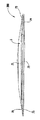
袋6は、1つの例示的な実施形態において、図3に示すように形成することができる。それに応じて、ライナーブランク103は、ガセットパネル107、108が互い及びそれぞれの側壁105、106と少なくとも部分的に対面接触するように、折り曲げ線113、109、110に沿って折り曲げることができる。さらに、側壁105、106は、ガセットパネル107、108の上方で互いと少なくとも部分的に対面接触状態に配置される。折り曲げ線109、110、113に沿って折り曲げる前、その後、及び/又はその間に、ライナーブランク103の内面101にある糊付け用エリア115、116(例えば図3の斜線領域)のそれぞれの少なくとも一部に、糊を塗布することができる。それに応じて、側壁105のシール領域121が側壁106のそれぞれのシール領域122と対面接触状態に配置された場合、シール領域はともに糊付けされ、袋6(図3)の各端部にシーム130を少なくとも部分的に形成する。さらに、側壁105のシールコーナー部123のそれぞれは、ガセットパネル107のそれぞれのシールコーナー部125に糊付けされ、側壁106のシールコーナー部124のそれぞれは、ガセットパネル108のそれぞれのシールコーナー部127に糊付けされ、シーム130のそれぞれの底端部に2つのシールコーナー132を形成する。袋6は、本開示から逸脱することなく、代替的な工程によってライナーブランク103から形成することができる。
The
1つの実施形態において、側壁105、106及びガセットパネル107、108の糊付け用エリア115、116外の部分は、糊の無い状態であり、糊付け用エリア外では、側壁とガセットパネルとが全体的にともに糊付けされないようになっている。それに応じて、側壁105、106を互いから離すことと、ガセットパネル107、108が離間した側壁105、106間で略同一平面に延びるようにガセットパネル107、108を折り曲げ線109、110、113に沿って折り曲げることとによって袋6を広げ、袋の内部空間を開くことができる。袋が折り畳まれた(collapsed)構成(例えば図3)又は開放された構成(例えば図17)のいずれにある間も、シーム130とシールコーナー132とは、袋6の閉鎖端部又は閉鎖側部を形成することができ、ガセットパネル107、108とシールコーナー132とは、袋6の閉鎖底部136を形成することができる。袋6は、折り曲げ線113とガセットパネル107、108とが側壁105、106間に配置されるようにガセットパネル107、108を折り曲げ線109、110、113に沿って内方に折り曲げることによって、開構成から閉構成に配置することができる。袋6は、本開示から逸脱することなく、代替的な工程によって折畳み構成と開構成との間で配置又は移動させることができる。
In one embodiment, portions of the
通常、カートンブランク3は、折り曲げ線26、27を中心に折り曲げて、開端スリーブ134(例えば、強化用スリーブ構成体)を形成することができる。例えば、図4〜図6を参照すると、袋6は、カートンブランク3と位置合わせすることができ(図4)、バックパネル23の遠位斜縁46、47は、折り曲げ線セグメント44、45に重ね合わせる及び/又は折り曲げ線セグメント44、45と整合させることができ(図5)、それにより、バックパネル23が貼付用フラップ25及び接着用領域61に少なくとも部分的に重ね合わされ、開端スリーブ134(図5及び図6)を形成する。したがって、バックパネル23は、接着用領域61によって貼付用フラップ25に糊付けすることができる。このシーケンス中、強化用スリーブ134は、接着用領域60によって袋6に貼付(例えば糊付け)することができる。例えば、側壁105、106は、接着用領域60においてそれぞれのフロントパネル21及びバックパネル23に糊付けすることができる。さらに、袋6のシーム130及びシールコーナー132の外側部分は、折り曲げて、図5に示すように側壁106に当接させることができる。代替的には、袋6のシーム130及びシールコーナー132の外側部分は、折り曲げて、側壁105に当接させることができる。袋6は、本開示から逸脱することなく、カートンブランク3/カートン5に別様に貼付することができる。例えば、カートンブランク3を折り曲げる前、又はカートン5を形成する間若しくはその後に、側壁105、106のいずれかをフロントパネル21及び/又はバックパネル23のいずれかに糊付けすることができる。
Typically, the carton blank 3 can be folded about
強化用スリーブ134を袋6に貼付すると、図7に示すように、ボトムパネル51を袋6に対して内方に折り曲げることができる。その後、ボトムパネル52及びボトム端部フラップ53をボトムパネル51に対して内方に折り曲げることができ、それにより、図8〜図10に示すように係止タブ55が係止ノッチ54に係止される。いくつかの実施形態によれば、ボトム端部フラップ53は、接着剤を受容してもよく、ボトムパネル51に固定して貼付することができる。代替的には、ボトム端部フラップ53は、ボトムパネル51に貼付されないままとすることができる。さらに、上述の折り曲げシーケンスは、本開示の範囲から逸脱することなく、いくつかの実施形態において変更又は省略してもよい。
When the reinforcing
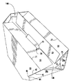
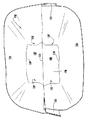
ボトムパネル51、52及びボトム端部フラップ53を折り曲げると、強化用カートン5が袋6を囲み、強化パッケージ200を形成する。1つの実施形態において、袋6は、カートン5の内部148においてフロントパネル21及び/又はバックパネル23の内面に糊付けされる。それに応じて、袋6の閉鎖底部136をカートン5の内部148に配置することができる。図示の実施形態では、パッケージ200を、第1の位置すなわち非起立位置すなわち非起立構成(図11〜図13)又は第2の位置すなわち起立位置すなわち起立構成(図17〜図20)にすることができる。第1の位置では、個々のパネル部分28a、28b、29a、及び29bは、パネル部分28a、29aがそれぞれのパネル部分28b、29bに概ね対向するように、それぞれの横折り曲げ線26、27に沿って折り曲げられている。図示の第1の位置すなわち非起立位置は、袋6の内部空間又は内部容積150の容積を減少及び/又は最小にし(例えば縮小し)、それにより強化パッケージが非起立状態又は半平坦状態(図12A及び図13)になる。図12Bに示すように、カートン5及び袋6は、1つの実施形態において完全に又は略完全に平坦にすることができる。非起立状態は、複数のパッケージを例えば出荷コンテナーに簡単に積載することと、その後の出荷先施設における整理とを容易にすることができる。一方で、図13に示すように、非起立状態は、内部容積150に製品を少なくとも部分的に充填するのを依然として容易にすることができる。その後、内部容積150は、1つの実施形態において任意の実施可能な方法でシールすることができる。
When the
個々のパネル部分28a、28b、29a、及び29bは、(内部容積150がシールされた状態又はシールされていない状態で)第1の位置すなわち非起立位置の強化パッケージ200を受けると、図14〜図17に示すパッケージの第2の位置すなわち起立位置においてパッケージの第1の側部28及び第2の側部29を形成するように屈曲又は配置される。それに応じて、1つの実施形態において、サイドパネル28、29は、それぞれの折り曲げ線26、27において内方に押し込まれる。パネル部分28a、28bがフロントパネル21とバックパネル23との間で略同一平面に延びるまで、サイドパネル28を折り曲げ線26、33、37に沿って折り曲げることができる。同様に1つの実施形態において、これと同時に、パネル部分29a、29bがフロントパネル21と貼付用フラップ25とバックパネル23との間で略同一平面に延びるまで、サイドパネル29を折り曲げ線27、40、43に沿って折り曲げることができる。さらに、フロントパネル21とバックパネル23とを互いから離すことで、ボトムパネル51、52をフロントパネルとバックパネルとの間で略同一平面に延びるように折り曲げ線71、72に沿って折り曲げ、カートン5の閉鎖底部を形成することができる。さらに、袋6の側壁105、106は、それぞれのフロントパネル21及びバックパネル23に糊付けされ、袋は、サイドパネル28、29を内方に動かすことで、フロントパネル及びバックパネルによって開位置に配置することができる。
Each
1つの実施形態において、サイドパネル28、29が頂点30a、30b間及び31a、31b間で最も幅広であるので、パッケージ200が第2の位置すなわち起立位置にある場合、サイドパネル28、29は、頂点30a、30b及び31a、31bのところでフロントパネル21及びバックパネル23に押し付けることができる。これにより張力を発生させることができ、この張力は、パネル部分28a、28b及び29a、29bを略同一平面位置に保持するのを援助することができる(例えば、サイドパネル28、29の折り曲げに抵抗するのを援助することができる)。さらに、フロントパネル21及びバックパネル23が縁70及び下側縁(例えば、折り曲げ線71、72)のところで最も幅広であるので、斜めの折り曲げ線セグメント34、35、38、39及び41、42、44、48は、サイドパネル28、29の折り曲げに抵抗するのを更に援助することができる。1つの実施形態において、サイドパネル28、29は、折り曲げ線33、37、40、43の斜めの折り曲げ線セグメントに起因して、カートン5の外側から略凹状となることができる。それに応じて、斜めの折り曲げ線セグメント34、35、38、39、41、42、44、48、頂点30a、30b、31a、31b、及びパネル部分28a、28b、29a、29bは、互い及び相互係止されるボトムパネル51、52(係止タブ55を含む)と協働して、パッケージ200を起立構成に保持するのを援助し得る係止構成部を形成することができる。1つの実施形態において、例えば、係止構成部は、折り曲げ線26、27のうちの一方又は双方を外方に押すことと、フロントパネル21及びバックパネル23を互いに向かって動かすこととによって、少なくとも部分的に係脱することができる。パッケージ200は、本開示から逸脱することなく、代替的な工程及び/又は特徴部を用いて非起立位置と起立位置との間で再構成することができる。
In one embodiment, when the
図17に示す第2の位置すなわち起立位置は、内部空間150の容積を拡大及び/又は最大にし、それによりパッケージ200が起立状態すなわち自己支持状態になる。パッケージ200が表面Sに接触する起立状態(例えば図17)である場合、底縁71、72、73、74、75、76は協働して、支持部を形成することができる。(例えば、サイドパネル28、29による相互係止作用において)底縁71、72、73、74、75、76によって形成された支持部は、パッケージを表面S上で直立位置に維持する。さらに、袋6の不透過性により、使用者は、容積150内の製品を水戻しするために内部容積150に液体(例えば、水、加熱水等)を少なくとも部分的に充填することができる。さらに、いくつかの実施形態によれば、(液体が充填されているか又は充填されていない)パッケージ200全体を、電子レンジ内で加熱し、袋6の内容物の調理及び/又は水で戻すことを容易にすることができる。いくつかの実施形態によれば、パッケージが完全には起立しない中間状態を含むパッケージ200の他の介在状態も適用可能である。さらに、例えば、加熱されると膨張するポップコーン等の膨張性食品が袋6に充填されている場合、調理プロセス中にフロントパネル21及びバックパネル23を離してサイドパネル28、29を少なくとも部分的に形成するように、自動的に起立する強化パッケージ200も適用可能である。
The second or upright position shown in FIG. 17 expands and / or maximizes the volume of the
概して、本明細書に記載したように、袋は袋素材によって形成することができるが、種々のプラスチック材料又は他の袋材料を用いることもでき、所望の材料でライニング又はコーティングすることもできる。本明細書に記載の強化用カートンは、クレーコーティング天然クラフト(「CCNK」)等のより硬質の材料で作製することができる。本明細書に記載のパッケージの構成部材を形成するのに、種々の厚紙、普通紙、プラスチック、若しくは他の合成材料又は天然材料等の他の材料を用いることもできる。 Generally, as described herein, the bag can be formed by the bag stock, but various plastic materials or other bag materials can also be used, and can be lined or coated with the desired material. The reinforcing cartons described herein can be made of harder materials such as clay coated natural kraft ("CCNK"). Other materials such as various cardboard, plain paper, plastics, or other synthetic or natural materials may also be used to form the components of the package described herein.
本開示によるブランクは、例えば、コート紙の板紙及び同様の材料から形成することができる。例えば、ブランクの内面及び/又は外面をクレーコートでコーティングすることができる。次に、クレーコート上に製品、広告、価格コード、及び他の情報又は画像を印刷してもよい。次に、ブランクに印刷されているあらゆる情報を保護するように、ブランクをワニスでコーティングすることができる。ブランクの片面又は両面を、例えば防湿層でコーティングすることもできる。上述の実施形態に応じて、ブランクは、通常の紙よりも重く硬質であるような厚さの板紙で作成してもよい。ブランクは、ボール紙、硬化紙等の他の材料、又はカートンが少なくとも概して上述したように機能することができるようにするのに適した特性を有する任意の他の材料で作成することもできる。ブランクは、選択されたパネル又はパネルセクションに1つ又は複数のシート状材料を積層又はコーティングすることもできる。 Blanks according to the present disclosure can be formed, for example, from coated paperboard and similar materials. For example, the inner and / or outer surface of the blank can be coated with a clay coat. Next, products, advertisements, price codes, and other information or images may be printed on the clay coat. The blank can then be varnished to protect any information printed on the blank. One or both sides of the blank can also be coated, for example with a moisture barrier. Depending on the embodiment described above, the blank may be made of paperboard of such a thickness that it is heavier and harder than regular paper. The blank can also be made of other materials such as cardboard, hardened paper, or any other material having properties suitable to allow the carton to function at least as generally described above. The blanks can also be laminated or coated with one or more sheet-like materials in selected panels or panel sections.
本開示の上述の実施形態によれば、折り曲げ線は、それに沿った折り曲げを容易にする、必ずしも直線状ではないが実質的に線状の任意の弱化形態とすることができる。本開示の範囲を狭めるためではないが、より詳細には、折り曲げ線は、所望の弱化線に沿って材料に圧潰部分を作る鈍いスコアリングナイフ等で形成される線等のスコア線、所望の弱化線に沿って材料に部分的に入れ込んだ切れ目、及び/又は所望の弱化線に沿って材料を部分的に貫通する一連の切れ目及び/又は材料を完全に貫通する一連の切れ目、並びにこれらの機能部の種々の組合せを含む。折り曲げ線を形成するのに切れ目付けが用いられる状況では、通常、切れ目付けは、分別ある使用者が折り曲げ線を誤って引裂線又は他の破断線とみなす可能性があるほど過度には深くない。 According to the above-described embodiments of the present disclosure, the fold line can be any substantially non-linear but substantially linear form of weakening that facilitates folding therealong. Although not to narrow the scope of the present disclosure, more particularly, the fold line is a score line, such as a line formed with a blunt scoring knife or the like that makes the material crush along the desired line of weakness, desired. A cut partially in the material along the line of weakness and / or a series of cuts partially penetrating the material along the desired line of weakness and / or a series of cuts completely through the material, and these Including various combinations of functional parts of In situations where scoring is used to form the fold line, the scoring is usually not too deep such that a sensible user may mistakenly consider the fold line as a tear line or other break line .
一例として、引裂線は、所望の弱化線に沿って材料に部分的に入れ込んだスリット、及び/又は所望の弱化線に沿って材料に部分的に入れ込むか、及び/又は完全に貫通する一連の離間したスリット、又はこれらの機能部の種々の組合せを含むことができる。より具体的な例としては、1つのタイプの引裂線は、引裂線を挟んで材料を通常は一時的に連結するようニック(例えば、ブリッジにやや似た材料の小片)が間に画成されるように隣接するスリットを僅かに離間させた、材料を完全に貫通する一連の離間したスリットの形態である。ニックは、引き裂き時に引裂線に沿って破断される。ニックは通常、引裂線において比較的僅かな割合を占めるものであり、代替的に、引裂線が連続した切れ目線であるように、ニックを引裂線から省くことができるか、又は引裂線上で破っておくことができる。すなわち、引裂線のそれぞれを連続したスリット等で置き換えることは、本開示の範囲内にある。例えば、本開示から逸脱することなく、切れ目線は、連続したスリットとすることができるか、又はスリットよりも幅広とすることができる。 As an example, the tear line may be a slit partially inserted into the material along the desired line of weakness and / or partially inserted into the material along the desired line of weakness and / or completely penetrate A series of spaced slits or various combinations of these features can be included. As a more specific example, one type of tear line is defined with a nick (eg, a small piece of material resembling a bridge) to generally temporarily connect the material across the tear line. Adjacent slits slightly spaced, and in the form of a series of spaced slits completely through the material. The nick is broken along the tear line at the time of tearing. The nick usually accounts for a relatively small percentage of the tear line, alternatively the nick can be omitted from the tear line, or the tear line can be broken, such that the tear line is a continuous slit line Can be That is, replacing each tear line with a continuous slit or the like is within the scope of the present disclosure. For example, without departing from the present disclosure, the score line can be a continuous slit or can be wider than the slit.
上記実施形態は、カートンの実施形態を組み立てる間に糊によってともに接着される1つ又は複数のパネルを有するものとして説明することができる。「糊」という用語は、カートンパネルを適所に固定するのに一般的に用いられる全ての態様の接着剤を包含することが意図される。 The above embodiments can be described as having one or more panels adhered together by glue during assembly of the carton embodiments. The term "glue" is intended to encompass all aspects of the adhesive commonly used to secure carton panels in place.
本開示の前述の説明は、本開示の種々の実施形態を例示及び説明する。本開示の範囲から逸脱することなく、種々の変更を上記構成内でなし得るので、上記説明に含まれるか又は添付図面に示されている全ての事項が、限定的な意味ではなく例示として解釈されることが意図される。さらに、本開示の範囲は、特許請求の範囲の範囲内にある上述の実施形態の種々の変更形態、組合せ、変形形態等をカバーする。加えて、本開示は、本開示の選択された実施形態のみを図示及び説明しているが、本開示は、種々の他の組合せ、変更形態、及び環境で用いることが可能であり、本明細書で述べられているような発明概念の範囲内の変形若しくは変更、上記教示と同等の変形若しくは変更、及び/又は関連技術分野の技術若しくは知識内にある変形若しくは変更を行うことが可能である。さらに、本開示の範囲から逸脱することなく、各実施形態の或る特定の機能部及び特徴を、選択的に入れ替えて、本開示の他の説明された実施形態及び説明されていない実施形態に適用することができる。 The foregoing description of the disclosure illustrates and describes various embodiments of the disclosure. Since various modifications can be made within the above configuration without departing from the scope of the present disclosure, all matters contained in the above description or shown in the accompanying drawings are interpreted as exemplification, not in a limiting sense. It is intended to be done. Furthermore, the scope of the present disclosure covers various modifications, combinations, variations and the like of the above-described embodiments that are within the scope of the claims. In addition, although the present disclosure illustrates and describes only selected embodiments of the present disclosure, the present disclosure may be used in various other combinations, modifications, and environments and is not limited to the present specification. Or variations within the scope of the inventive concept as described in the text, variations or modifications equivalent to the above teaching, and / or variations or modifications within the skill or knowledge of the relevant art . Moreover, certain features and characteristics of each embodiment can be selectively interchanged with other described embodiments and non-described embodiments of the present disclosure without departing from the scope of the present disclosure. It can apply.
Claims (14)
複数のパネルを有するカートンであって、該複数のパネルは、該カートンの内部の回りに少なくとも部分的に延び、該複数のパネルは、フロントパネルと、該フロントパネルに折り曲げ可能につながっている第1のサイドパネルと、前記フロントパネルに折り曲げ可能につながっている第2のサイドパネルと、前記第1のサイドパネル及び前記第2のサイドパネルのうちの少なくとも一方に折り曲げ可能につながっている少なくとも1つのバックパネルと、前記バックパネルに折り曲げ可能につながっている第1のボトムパネルと前記フロントパネルに折り曲げ可能につながっている第2のボトムパネルとを含む、カートンと、
少なくとも部分的に開放した端部と、少なくとも部分的に閉鎖した端部と、製品を保持する内部空間とを有する袋であって、該袋は、前記カートンの前記内部に少なくとも部分的に収容される、袋と、
を備え、
前記袋は、第1の側壁及び第2の側壁を有し、前記袋の前記少なくとも部分的に閉鎖した端部は、第1の折り曲げ線に沿って第2のガセットパネルに折り曲げ可能につながっている第1のガセットパネルを含み、前記第1の側壁は、第2の折り曲げ線に沿って前記第1のガセットパネルに折り曲げ可能につながっており、前記第2の側壁は、第3の折り曲げ線に沿って前記第2のガセットパネルに折り曲げ可能につながっており、
前記カートンは、前記袋の前記内部空間が少なくとも部分的に縮小し、前記第1のガセットパネルと前記第2のガセットパネルが少なくとも部分的に互いに対して折り曲げられている非起立位置と、前記袋の前記内部空間が拡大し、前記第1のガセットパネルと前記第2のガセットパネルが拡がる起立位置とに配置可能であり、前記カートンは、前記袋を前記起立位置に支持するように構成されており、
前記カートンが非起立位置にあるとき、前記第1のボトムパネルと前記第2のボトムパネルは、前記カートンの内部において少なくとも部分的に互いに重ね合わさっており、
前記少なくとも1つのボトムパネルは、係止タブを含み、該係止タブは前記第2のボトムパネルから延びるとともに、前記非起立位置から前記起立位置に前記カートンが拡がるのに先立って前記第1のボトムパネルの縁内に形成された係止ノッチに係合可能であり、前記強化パッケージは、前記係止タブによって少なくとも部分的に中断される折り曲げ線に沿って前記第2のボトムパネルに折り曲げ可能につながっているボトムフラップを更に備え、前記係止タブは、前記ボトムフラップにおいて切れ目線によって少なくとも部分的に画定される、強化パッケージ。 A reinforced package for holding a product, the reinforced package comprising:
A carton having a plurality of panels, the plurality of panels extending at least partially around an interior of the carton, the plurality of panels being foldably connected to a front panel and the front panel A first side panel, a second side panel foldably connected to the front panel, and at least one foldably connected to at least one of the first side panel and the second side panel A carton comprising two back panels, a first bottom panel foldably connected to the back panel, and a second bottom panel foldably connected to the front panel;
A bag having an at least partially open end, an at least partially closed end, and an interior space for holding a product, the bag at least partially housed within the interior of the carton , Bags,
Equipped with
The bag has a first side wall and a second side wall, and the at least partially closed end of the bag is foldably connected to a second gusset panel along a first fold line A first gusset panel, the first side wall being foldably connected to the first gusset panel along a second fold line, the second side wall being a third fold line Is foldably connected to the second gusset panel along the
A non-upright position in which the carton has the internal space of the bag at least partially reduced and the first gusset panel and the second gusset panel are at least partially folded relative to one another; The interior space is expanded and can be arranged in the erected position where the first gusset panel and the second gusset panel expand, and the carton is configured to support the bag in the erected position Yes,
When the carton is in the non-upstanding position, the first bottom panel and the second bottom panel at least partially overlap one another in the interior of the carton ;
The at least one bottom panel includes a locking tab, the locking tab extending from the second bottom panel, and the first prior to the carton expanding from the non-elevated position to the raised position. Engaging with a locking notch formed in the edge of the bottom panel, the reinforcing package being foldable into the second bottom panel along a fold line at least partially interrupted by the locking tab further comprising a by and bottom flaps connected to said locking tab, Ru at least partially defined by cut lines in the bottom flaps, reinforcement package.
前記カートンが前記起立位置にある場合、前記第1のガセットパネルと前記第2のガセットパネルとは互いに略同一平面にあり、前記カートンが前記非起立位置にある場合、前記第1のガセットパネルと前記第2のガセットパネルとは前記第1の折り曲げ線に沿って互いに対して少なくとも部分的に折り曲げられており、前記第1のガセットパネル及び前記第2のガセットパネルは、前記カートンが前記非起立位置にある場合、概ね前記第1の側壁と前記第2の側壁との間に配置される、請求項1に記載の強化パッケージ。 Each of the first side wall and the second side wall extends generally upwardly from the at least partially closed end of the bag;
The first gusset panel and the second gusset panel are substantially coplanar with each other when the carton is in the upright position, and with the first gusset panel when the carton is in the non-erect position. The second gusset panel is at least partially folded relative to each other along the first fold line, and the first gusset panel and the second gusset panel indicate that the carton is not erected The reinforced package of claim 1, wherein when in position, it is disposed generally between the first side wall and the second side wall.
複数のパネルを有するカートンブランクを得ることであって、該複数のパネルは、フロントパネルと、該フロントパネルに折り曲げ可能につながっている第1のサイドパネルと、前記フロントパネルに折り曲げ可能につながっている第2のサイドパネルと、前記第1のサイドパネル及び前記第2のサイドパネルのうちの少なくとも一方に折り曲げ可能につながっている少なくとも1つのバックパネルと、前記バックパネルに折り曲げ可能につながっている第1のボトムパネルと、前記フロントパネルに折り曲げ可能につながっている第2のボトムパネルと、を含み、
ライナーブランクを得ることと、
少なくとも部分的に開放した端部と、少なくとも部分的に閉鎖した端部と、第1の側壁と、第2の側壁と、製品を保持する内部空間とを有するように、前記ライナーブランクから袋を形成することと、
前記袋の前記少なくとも部分的に閉鎖した端部は、第1の折り曲げ線に沿って第2のガセットパネルに折り曲げ可能につながっている第1のガセットパネルを含み、前記第1の側壁は、第2の折り曲げ線に沿って前記第1のガセットパネルに折り曲げ可能につながっており、前記第2の側壁は、第3の折り曲げ線に沿って前記第2のガセットパネルに折り曲げ可能につながっており、
前記袋の少なくとも一部を前記カートンブランクの前記フロントパネル及び前記バックパネルのうちの少なくとも一方に貼付することと、
前記複数のパネルによって少なくとも部分的に画定されるカートンの内部を形成することであって、開端スリーブを形成することを含むことと、
を含み、
前記カートンは、前記袋の前記内部空間が少なくとも部分的に縮小し、前記第1のガセットパネルと前記第2のガセットパネルが少なくとも部分的に互いに対して折り曲げられている非起立位置と、前記袋の前記内部空間が拡大し、前記第1のガセットパネルと前記第2のガセットパネルが拡がる起立位置とに配置可能であり、前記カートンは、前記袋を前記起立位置に支持するように構成されており、
前記カートンが非起立位置にあるとき、前記第1のボトムパネルと前記第2のボトムパネルは、前記カートンの内部において少なくとも部分的に互いに重ね合わさっており、
前記少なくとも1つのボトムパネルは、係止タブを含み、該係止タブは前記第2のボトムパネルから延びるとともに、前記非起立位置から前記起立位置に前記カートンが拡がるのに先立って前記第1のボトムパネルの縁内に形成された係止ノッチに係合可能であり、前記強化パッケージは、前記係止タブによって少なくとも部分的に中断される折り曲げ線に沿って前記第2のボトムパネルに折り曲げ可能につながっているボトムフラップを更に備え、前記係止タブは、前記ボトムフラップにおいて切れ目線によって少なくとも部分的に画定される、方法。 A method of forming a reinforced package for holding a product comprising:
Providing a carton blank having a plurality of panels, the plurality of panels being foldably connected to the front panel, a first side panel foldably connected to the front panel, and the front panel And at least one back panel foldably connected to at least one of the first side panel and the second side panel, and foldably connected to the back panel A first bottom panel and a second bottom panel foldably connected to the front panel;
Obtaining a liner blank,
The bag from the liner blank is provided having an at least partially open end, an at least partially closed end, a first side wall, a second side wall, and an interior space for holding a product. Forming and
The at least partially closed end of the bag includes a first gusset panel foldably connected to a second gusset panel along a first fold line, the first sidewall being The second gusset panel is foldably connected to the first gusset panel along a folding line of 2, and the second side wall is foldably connected to the second gusset panel along a third folding line,
Sticking at least a portion of the bag to at least one of the front panel and the back panel of the carton blank;
Forming an interior of the carton at least partially defined by the plurality of panels, including forming an open end sleeve;
Including
A non-upright position in which the carton has the internal space of the bag at least partially reduced and the first gusset panel and the second gusset panel are at least partially folded relative to one another; The interior space is expanded and can be arranged in the erected position where the first gusset panel and the second gusset panel expand, and the carton is configured to support the bag in the erected position Yes,
When the carton is in the non-upstanding position, the first bottom panel and the second bottom panel at least partially overlap one another in the interior of the carton ;
The at least one bottom panel includes a locking tab, the locking tab extending from the second bottom panel, and the first prior to the carton expanding from the non-elevated position to the raised position. Engaging with a locking notch formed in the edge of the bottom panel, the reinforcing package being foldable into the second bottom panel along a fold line at least partially interrupted by the locking tab further comprising a by and bottom flaps connected to said locking tab, Ru at least partially defined by cut lines in the bottom flaps, method.
前記第1のサイドパネルは、第1の折り曲げ線に沿って前記フロントパネルに、また第2の折り曲げ線に沿って前記バックパネルに折り曲げ可能につながっており、前記第2のサイドパネルは、第3の折り曲げ線に沿って前記フロントパネルに、また第4の折り曲げ線に沿って貼付用フラップに折り曲げ可能につながっており、
前記カートンの前記内部を形成することは、前記第1のサイドパネル及び前記第2のサイドパネルをそれぞれの前記第1の横折り曲げ線及び前記第2の横折り曲げ線に沿って折り曲げることと、前記バックパネルと前記貼付用フラップとを少なくとも部分的に重ね合わせることとを含む、請求項10に記載の方法。 The first side panel includes a first panel portion foldably connected to a second panel portion along a first lateral fold line, and the second side panel includes a second lateral fold. Including a third panel portion foldably connected to the fourth panel portion along a line;
The first side panel is foldably connected to the front panel along a first fold line and to the back panel along a second fold line, the second side panel being It is foldably connected to the front panel along a fold line 3 and to the affixing flap along a fourth fold line,
Forming the interior of the carton comprises: bending the first side panel and the second side panel along respective first and second transverse fold lines; 11. The method of claim 10, comprising at least partially overlapping a back panel and the application flap.
Applications Claiming Priority (3)
| Application Number | Priority Date | Filing Date | Title |
|---|---|---|---|
| US201361960712P | 2013-09-25 | 2013-09-25 | |
| US61/960,712 | 2013-09-25 | ||
| PCT/US2014/057385 WO2015048242A1 (en) | 2013-09-25 | 2014-09-25 | Reinforced package |
Publications (3)
| Publication Number | Publication Date |
|---|---|
| JP2016537264A JP2016537264A (en) | 2016-12-01 |
| JP2016537264A5 JP2016537264A5 (en) | 2017-03-23 |
| JP6426719B2 true JP6426719B2 (en) | 2018-11-21 |
Family
ID=52690090
Family Applications (1)
| Application Number | Title | Priority Date | Filing Date |
|---|---|---|---|
| JP2016517471A Active JP6426719B2 (en) | 2013-09-25 | 2014-09-25 | Reinforcement package |
Country Status (9)
| Country | Link |
|---|---|
| US (1) | US9758275B2 (en) |
| EP (1) | EP3049338B1 (en) |
| JP (1) | JP6426719B2 (en) |
| CN (1) | CN105555672B (en) |
| BR (1) | BR112016001763B1 (en) |
| CA (1) | CA2918510C (en) |
| ES (1) | ES2708382T3 (en) |
| MX (1) | MX2016003466A (en) |
| WO (1) | WO2015048242A1 (en) |
Families Citing this family (31)
| Publication number | Priority date | Publication date | Assignee | Title |
|---|---|---|---|---|
| GB201205243D0 (en) | 2012-03-26 | 2012-05-09 | Kraft Foods R & D Inc | Packaging and method of opening |
| GB2511560B (en) | 2013-03-07 | 2018-11-14 | Mondelez Uk R&D Ltd | Improved Packaging and Method of Forming Packaging |
| GB2511559B (en) | 2013-03-07 | 2018-11-14 | Mondelez Uk R&D Ltd | Improved Packaging and Method of Forming Packaging |
| CN105555672B (en) | 2013-09-25 | 2018-05-25 | 印刷包装国际有限责任公司 | Enhance package |
| US9771176B2 (en) | 2013-09-25 | 2017-09-26 | Graphic Packaging International, Inc. | Reinforced package |
| US9957080B2 (en) | 2013-09-25 | 2018-05-01 | Graphic Packaging International, Llc | Reinforced package |
| BR112017022499B1 (en) | 2015-04-29 | 2022-07-26 | Graphic Packaging International, Llc | METHOD FOR FORMING REINFORCED PACKAGING, AND SYSTEM FOR FORMING REINFORCED PACKAGING |
| AU2016255501B2 (en) | 2015-04-29 | 2019-01-03 | Graphic Packaging International, Llc | Method and system for forming packages |
| EP3322659B1 (en) | 2015-07-14 | 2023-09-06 | Graphic Packaging International, LLC | Method and system for forming packages |
| JP6833805B2 (en) * | 2015-07-23 | 2021-02-24 | グラフィック パッケージング インターナショナル エルエルシー | Reinforced package |
| US10023349B2 (en) * | 2015-08-21 | 2018-07-17 | Graphic Packaging International, Llc | Reinforced package |
| WO2017146698A1 (en) | 2016-02-24 | 2017-08-31 | Bemis Company, Inc. | Multilayer pouch with heat-shrinkable layer |
| CA3021937C (en) * | 2016-06-24 | 2020-12-29 | Graphic Packaging International, Llc | Reinforced package |
| US10173805B2 (en) * | 2016-07-14 | 2019-01-08 | Graphic Packaging International, Llc | Reclosable carton |
| US10232976B2 (en) | 2016-07-25 | 2019-03-19 | Graphic Packaging International, Llc | Dispensing carton |
| CA3038134C (en) | 2016-11-14 | 2021-01-05 | Graphic Packaging International, Llc | Reconfigurable carton and package |
| DK3570715T3 (en) * | 2017-01-20 | 2021-11-08 | Hygienius Intellectual Property B V | Expandable disposable liquid container and blank |
| FI128578B (en) * | 2017-11-13 | 2020-08-14 | Jospak Oy | Stackable product package and method for producing the same and blank for a product package |
| BR112019028030A2 (en) | 2017-08-09 | 2020-07-07 | Graphic Packaging International, Llc | method of at least partially forming reinforced packages, system for at least partially forming reinforced packages, method of at least partially forming reinforced packages, and method of at least partially forming reinforced packages |
| AU2019253436B2 (en) * | 2018-04-09 | 2022-03-24 | Graphic Packaging International, Llc | Carton with liner |
| WO2019220321A1 (en) * | 2018-05-14 | 2019-11-21 | Graphic Packaging International, Llc | Method and system for forming packages |
| CA3104186C (en) | 2018-07-09 | 2023-10-03 | Graphic Packaging International, Llc | Method and system for forming packages |
| JP7155735B2 (en) * | 2018-08-10 | 2022-10-19 | 大日本印刷株式会社 | Composite container |
| EP3917848A4 (en) * | 2019-01-28 | 2022-11-02 | Graphic Packaging International, LLC | Reinforced package |
| JP7338274B2 (en) * | 2019-04-08 | 2023-09-05 | 大日本印刷株式会社 | Box-shaped container, box-shaped packaged food and its usage |
| CA3081438A1 (en) | 2019-05-31 | 2020-11-30 | BML Solutions LLC | Food holder |
| WO2021102102A1 (en) | 2019-11-22 | 2021-05-27 | Graphic Packaging International, Llc | Container with liner |
| USD1042113S1 (en) * | 2020-01-24 | 2024-09-17 | Graphic Packaging International, Llc | Reinforcing carton |
| JP7442378B2 (en) * | 2020-04-10 | 2024-03-04 | 共同印刷株式会社 | freestanding bag |
| CA3204463A1 (en) | 2020-12-22 | 2022-06-30 | Graphic Packaging International, Llc | End flap engagement assembly for erecting cartons and related systems and methods |
| US20230312166A1 (en) * | 2022-03-29 | 2023-10-05 | Graphic Packaging International, Llc | Carton With Opening Features |
Family Cites Families (208)
| Publication number | Priority date | Publication date | Assignee | Title |
|---|---|---|---|---|
| USRE23096E (en) | 1949-04-05 | Moisturepboof package | ||
| US1474088A (en) | 1920-07-26 | 1923-11-13 | Richard S Reynolds | Collapsible metal box |
| US1516090A (en) | 1923-03-28 | 1924-11-18 | Benjamin L Gary | Carton |
| US1664111A (en) | 1927-03-23 | 1928-03-27 | W H Marvin Company | Carton |
| US2092858A (en) | 1934-03-12 | 1937-09-14 | Johnson Automatic Sealer Co Lt | Bag and method of making same |
| US2099257A (en) | 1935-10-04 | 1937-11-16 | Edna May Bergstein | Container |
| US2250249A (en) | 1936-02-04 | 1941-07-22 | Bergstein Robert Morris | Container |
| US2107946A (en) | 1936-09-15 | 1938-02-08 | Bloomer Bros Co | Carton construction |
| US2132966A (en) | 1937-03-19 | 1938-10-11 | Edson A O'brien | Contection |
| US2197133A (en) | 1937-06-28 | 1940-04-16 | Malmgren George | Electrical amalgamator |
| US2166388A (en) | 1937-12-20 | 1939-07-18 | Edna May Bergstein | Machine for combining bags and cartons |
| US2282207A (en) | 1939-01-06 | 1942-05-05 | Kraft Cheese Company | Container and method of making the same |
| US2286465A (en) | 1941-02-06 | 1942-06-16 | Clement Erlin | Paper cup opener |
| US2553923A (en) | 1948-09-11 | 1951-05-22 | Ralph E Lambert | Wrapping paper comprising single face corrugated board and integral fly webs |
| US2835435A (en) | 1950-09-05 | 1958-05-20 | Charles D Mullinix | Packaging means |
| US2870023A (en) | 1951-07-05 | 1959-01-20 | Clarence W Vogt | Enwrapments for plastic and like substances |
| US2913161A (en) | 1953-06-15 | 1959-11-17 | Waldorf Paper Products Co | Plant package |
| DE1060313B (en) * | 1957-02-05 | 1959-06-25 | Hansjuergen Mensing | Packaging in the form of a folding box |
| US2987402A (en) | 1958-07-11 | 1961-06-06 | Milprint Inc | Composite food package and method of making same |
| US3142231A (en) | 1960-05-23 | 1964-07-28 | Christensson Od Wikar | Arrangement in machines for the production of lined packages |
| DK108480C (en) | 1961-12-05 | 1967-12-18 | Knud Bjarnoe | Packaging. |
| US3142430A (en) | 1963-03-15 | 1964-07-28 | American Can Co | Carton |
| CH405152A (en) | 1963-11-27 | 1965-12-31 | Steiger Ag | Cut to produce a weldable folding box |
| US3357631A (en) | 1963-12-03 | 1967-12-12 | Continental Can Co | Recessed ice-cream carton with tuck-in reclosure |
| US3194471A (en) | 1964-06-04 | 1965-07-13 | Inland Container Corp | Bulk container device |
| US3240419A (en) | 1964-09-15 | 1966-03-15 | American Can Co | Carton with integral tear-strip sealing means |
| US3249286A (en) | 1964-09-28 | 1966-05-03 | Monsanto Co | Reinforced plastic bag |
| US3324998A (en) | 1965-10-23 | 1967-06-13 | Reynolds Metals Co | Container and blanks for making same |
| US3399818A (en) | 1966-05-17 | 1968-09-03 | Douglass M. Stegner | Container |
| US3459357A (en) | 1967-01-05 | 1969-08-05 | Union Camp Corp | Bag-in-a-box |
| US3428235A (en) | 1967-09-22 | 1969-02-18 | Pasquale Randazzo | Can carriers |
| US3482758A (en) | 1968-01-12 | 1969-12-09 | Interstate Folding Box Co | Prelined two wall packet |
| US3627541A (en) | 1968-11-21 | 1971-12-14 | Reynolds Metals Co | Method of packaging a food product in a carton |
| US3515333A (en) | 1969-02-13 | 1970-06-02 | Eastman Kodak Co | Combination wrap-base roll box |
| US3659777A (en) | 1969-06-30 | 1972-05-02 | Takahi Kanada | Reinforced package |
| US3576290A (en) | 1969-08-01 | 1971-04-27 | Union Camp Corp | Bag in a box for frozen eggs or the like |
| US3637130A (en) | 1970-08-10 | 1972-01-25 | Reynolds Metals Co | Container and blanks for making same |
| US3945870A (en) | 1973-07-24 | 1976-03-23 | Johnsen Edward L | Method of making multi-layer composite and articles therefrom |
| US3964669A (en) | 1975-09-02 | 1976-06-22 | Milprint, Inc. | Composite wrapper combining rigid and flexible elements |
| US4011983A (en) | 1976-02-24 | 1977-03-15 | William Henry Greene | Bag container |
| US4082216A (en) * | 1977-02-07 | 1978-04-04 | Eli Lilly And Company | Carton and bag container |
| DE2721333C2 (en) | 1977-05-12 | 1986-06-12 | Altstädter Verpackungsvertriebs Gesellschaft mbH, 6102 Pfungstadt | Device for applying coating strips to a web of container blanks |
| JPS5521939U (en) * | 1978-07-31 | 1980-02-13 | ||
| JPS5550314A (en) | 1978-10-11 | 1980-04-12 | Isao Hirata | Simple cup |
| US4228945A (en) | 1979-03-05 | 1980-10-21 | Champion International Corporation | Food carton for microwave heating |
| US4313542A (en) | 1979-07-13 | 1982-02-02 | Champion International Corporation | Single-serving pie carton and blank |
| US4312451A (en) | 1979-07-20 | 1982-01-26 | Westvaco Corporation | Self standing flanged tray with integral lid |
| US4267955A (en) | 1979-07-25 | 1981-05-19 | Diamond International Corporation | Quickly erected scoop-type carton and layout for cutting |
| JPS5944260B2 (en) * | 1981-02-09 | 1984-10-27 | 勲 平田 | Simple tip |
| US4457483A (en) | 1981-10-08 | 1984-07-03 | Laureat Gagne | Collapsible support for garbage bags |
| JPS5873756U (en) | 1981-11-11 | 1983-05-18 | 北海製罐株式会社 | composite packaging container |
| US4398636A (en) | 1981-11-13 | 1983-08-16 | The Mead Corporation | Article case and blank therefor |
| US4484683A (en) | 1982-02-19 | 1984-11-27 | Ralston Purina Company | Reclosable carton |
| JPS58183341U (en) * | 1982-05-31 | 1983-12-06 | 新井 徹 | free standing container |
| US4477014A (en) | 1983-05-04 | 1984-10-16 | Container Corporation Of America | Triangular carton and opening means therefor |
| US4494785A (en) | 1983-06-20 | 1985-01-22 | Song Ho K | Adjustable handheld round sandwich holder |
| US4575000A (en) | 1984-11-09 | 1986-03-11 | International Paper Company | Food wrapper package |
| US4754914A (en) | 1986-09-26 | 1988-07-05 | Rock-Tenn Company | Package for wrapping food or other articles |
| USRE34683E (en) | 1987-03-10 | 1994-08-02 | James River Corporation Of Virginia | Control of microwave interactive heating by patterned deactivation |
| US4865921A (en) | 1987-03-10 | 1989-09-12 | James Riker Corporation Of Virginia | Microwave interactive laminate |
| US4785696A (en) | 1987-04-03 | 1988-11-22 | Kraft, Inc. | High-speed apparatus for forming sheets from a web |
| US4775771A (en) | 1987-07-30 | 1988-10-04 | James River Corporation | Sleeve for crisping and browning of foods in a microwave oven and package and method utilizing same |
| US5034234A (en) | 1988-03-15 | 1991-07-23 | Golden Valley Microwave Foods Inc. | Microwave heating and serving package |
| US5175404A (en) | 1988-03-15 | 1992-12-29 | Golden Valley Microwave Foods Inc. | Microwave receptive heating sheets and packages containing them |
| US5080643A (en) | 1988-03-21 | 1992-01-14 | Dow Brands Inc. | Method of making a stand-up plastic bag |
| US4919785A (en) | 1988-04-28 | 1990-04-24 | Kraft General Foods, Inc. | Microwave carton |
| CA1292934C (en) | 1988-05-20 | 1991-12-10 | Donald G. Beckett | Microwave heating material |
| GB8820129D0 (en) | 1988-08-24 | 1988-09-28 | Schering Agrochemicals Ltd | Fungicides |
| US5028147A (en) | 1988-08-25 | 1991-07-02 | Bell Paper Company | Integrated container for meat products |
| US5410135A (en) | 1988-09-01 | 1995-04-25 | James River Paper Company, Inc. | Self limiting microwave heaters |
| US4890439A (en) | 1988-11-09 | 1990-01-02 | James River Corporation | Flexible disposable material for forming a food container for microwave cooking |
| US4940200A (en) | 1989-01-13 | 1990-07-10 | Wilmarc, Inc. | Support for a non-self supporting container |
| US5519195A (en) | 1989-02-09 | 1996-05-21 | Beckett Technologies Corp. | Methods and devices used in the microwave heating of foods and other materials |
| US4930639A (en) | 1989-08-02 | 1990-06-05 | Westvaco Corporation | Ovenable food container with removable lid |
| CA2009207A1 (en) | 1990-02-02 | 1991-08-02 | D. Gregory Beckett | Controlled heating of foodstuffs by microwave energy |
| JPH0413568U (en) | 1990-05-18 | 1992-02-04 | ||
| US5096723A (en) | 1990-07-23 | 1992-03-17 | Golden Valley Microwave Foods Inc. | Microwave food heating package with serving tray |
| US5071062A (en) | 1991-01-28 | 1991-12-10 | Bradley David E | Reducible carton for pizza pies and the like |
| US5078273A (en) | 1991-02-12 | 1992-01-07 | James River Corporation Of Virginia | Microwave carton and blank for forming the same |
| CA2041062C (en) | 1991-02-14 | 2000-11-28 | D. Gregory Beckett | Demetallizing procedure |
| US5628921A (en) | 1991-02-14 | 1997-05-13 | Beckett Technologies Corp. | Demetallizing procedure |
| US5266386A (en) | 1991-02-14 | 1993-11-30 | Beckett Industries Inc. | Demetallizing procedure |
| US5221419A (en) | 1991-02-19 | 1993-06-22 | Beckett Industries Inc. | Method for forming laminate for microwave oven package |
| US5213902A (en) | 1991-02-19 | 1993-05-25 | Beckett Industries Inc. | Microwave oven package |
| US5260537A (en) | 1991-06-17 | 1993-11-09 | Beckett Industries Inc. | Microwave heating structure |
| GB9201932D0 (en) | 1992-01-29 | 1992-03-18 | Beckett Ind Inc | Novel microwave heating structure |
| US5337951A (en) | 1992-08-05 | 1994-08-16 | Waldorf Corporation | Sturdy sandwich carton |
| US5330099A (en) | 1993-04-20 | 1994-07-19 | International Paper Company | Container for foodstuffs |
| JP2564259Y2 (en) * | 1993-04-22 | 1998-03-04 | 益弘 光山 | Case |
| US5326022A (en) | 1993-06-10 | 1994-07-05 | Gulf States Paper Corporation | Carton with vent opening arrangement |
| US5346311A (en) | 1993-09-20 | 1994-09-13 | Siler Buzz L | Sealable open-mouth bag |
| US5424517A (en) | 1993-10-27 | 1995-06-13 | James River Paper Company, Inc. | Microwave impedance matching film for microwave cooking |
| US5411165A (en) | 1993-11-02 | 1995-05-02 | Ellis; Thomas J. | Drawer and insert for rapid removal of valuables |
| US5492269A (en) * | 1994-04-26 | 1996-02-20 | Sunglare Merchandising Inc. | Collapsible/foldable container |
| US5510132A (en) | 1994-06-07 | 1996-04-23 | Conagra, Inc. | Method for cooking a food item in microwave heating package having end flaps for elevating and venting the package |
| US5585027A (en) | 1994-06-10 | 1996-12-17 | Young; Robert C. | Microwave susceptive reheating support with perforations enabling change of size and/or shape of the substrate |
| US5427267B1 (en) | 1994-07-11 | 1997-05-13 | Samuel A Willman | Container with inner bag sealing feature |
| US5615795A (en) | 1995-01-03 | 1997-04-01 | Tipps; Steven V. | Hazardous materials container |
| US5484100A (en) | 1995-03-24 | 1996-01-16 | Westvaco Corporation | Tapered, hexagonal paperboard carton |
| BR9610417A (en) | 1995-08-18 | 1999-12-21 | Pethick & Money Ltd | "improvements in or related to packaging for goods articles" |
| US5759422A (en) | 1996-02-14 | 1998-06-02 | Fort James Corporation | Patterned metal foil laminate and method for making same |
| US5800724A (en) | 1996-02-14 | 1998-09-01 | Fort James Corporation | Patterned metal foil laminate and method for making same |
| FR2749281B1 (en) | 1996-05-28 | 1998-07-31 | Capy Gilbert | DEVICE FOR REINFORCING A PLEATED PACKAGE FOR CONVEX BODIES |
| AU4006197A (en) | 1996-08-26 | 1998-03-19 | Fort James Corporation | Microwavable package |
| DE69709756T2 (en) | 1996-08-26 | 2002-08-22 | Graphic Packaging Corp., Golden | MICROWAVE HEATABLE CONTAINER |
| EP0891285B1 (en) | 1997-01-29 | 2003-11-05 | Graphic Packaging Corporation | Microwave oven heating element having broken loops |
| US7205016B2 (en) | 1997-03-13 | 2007-04-17 | Safefresh Technologies, Llc | Packages and methods for processing food products |
| US6350057B1 (en) | 1997-05-22 | 2002-02-26 | Sealstrip Corp. | Reinforced reclosable package seals |
| US5944425A (en) | 1997-05-22 | 1999-08-31 | Forman; Harold M | Packages with unitarilly formed resealable closure |
| JPH10338244A (en) | 1997-06-03 | 1998-12-22 | Houseki Planning:Kk | Sealed bag with tape stuck thereto and its production |
| US5938110A (en) | 1997-07-14 | 1999-08-17 | International Paper Company | Modular interlockable packaging |
| US5964161A (en) | 1997-10-30 | 1999-10-12 | Conway; Kay Christine | Expandable tray |
| GB2331291A (en) | 1997-11-18 | 1999-05-19 | Rapid Action Packaging Ltd | Containers for foodstuffs |
| US6414290B1 (en) | 1998-03-19 | 2002-07-02 | Graphic Packaging Corporation | Patterned microwave susceptor |
| SE9801291L (en) | 1998-04-14 | 1999-03-22 | Production Process Internation | Packaging |
| GB2339756B (en) | 1998-07-17 | 2002-07-17 | Pethick & Money Ltd | Improvements in or relating to food packages with attached wrapping material |
| US6082613A (en) | 1998-08-10 | 2000-07-04 | General Mills, Inc. | Interplant bulk shipment containers |
| US6063415A (en) | 1999-01-21 | 2000-05-16 | Kraft Foods, Inc. | Microwaveable food container and method of using same |
| US6132351A (en) | 1999-05-28 | 2000-10-17 | The Hudson-Sharp Machine Co. | Method and apparatus for making internally-reinforced bag assembly |
| US6494619B1 (en) | 1999-06-07 | 2002-12-17 | Alfred Sulpizio | Disposable lawn bag |
| CA2315559C (en) | 1999-08-10 | 2009-01-20 | Fort James Corporation | Sandwich wrap and method of unwrapping a sandwich |
| FR2798369B1 (en) | 1999-09-09 | 2001-11-30 | Unisabi Sa | REINFORCED PACKAGING FOR FLOWABLE PRODUCTS |
| US20030002755A1 (en) * | 1999-09-09 | 2003-01-02 | Mars Incorporated | Pillow pouch packaging with reinforcing elements |
| US6433322B2 (en) | 1999-09-20 | 2002-08-13 | Graphic Packaging Corporation | Abuse-tolerant metallic packaging materials for microwave cooking |
| US6204492B1 (en) | 1999-09-20 | 2001-03-20 | Graphic Packaging Corporation | Abuse-tolerant metallic packaging materials for microwave cooking |
| US20010048022A1 (en) | 2000-04-27 | 2001-12-06 | Zoeckler Michael D. | Paperboard cartons with laminated reinforcing ribbons and transitioned scores and method of making same |
| US8317671B1 (en) | 2000-04-27 | 2012-11-27 | Graphic Packaging International, Inc. | Paperboard cartons with laminated reinforcing ribbons and method of making same |
| US6401927B1 (en) | 2000-05-11 | 2002-06-11 | Marcia G. Miller | Pop-up food tray for combination meals |
| US6695202B2 (en) | 2000-05-18 | 2004-02-24 | Field Container Company, Lp. | Disposable food service container |
| GB2365000B (en) | 2000-07-24 | 2004-06-23 | Rye Dev Ltd | A package |
| US6986920B2 (en) | 2000-10-23 | 2006-01-17 | Sealstrip Corporation | Composite web for making gusseted packages |
| US6349874B1 (en) * | 2001-02-27 | 2002-02-26 | Bell Paper Inc. | Carton with integral discrete compartment |
| US6869387B2 (en) | 2001-09-19 | 2005-03-22 | Polymer Packaging, Inc. | Former for forming a rectangular bag tube |
| US6717121B2 (en) | 2001-09-28 | 2004-04-06 | Graphic Packaging International, Inc. | Patterned microwave susceptor element and microwave container incorporating same |
| US6683289B2 (en) | 2001-10-29 | 2004-01-27 | Mars Incorporated | Hand-held food package |
| US6744028B2 (en) | 2001-10-29 | 2004-06-01 | Mars Incorporated | Semi-rigid hand-held food package |
| US6677563B2 (en) | 2001-12-14 | 2004-01-13 | Graphic Packaging Corporation | Abuse-tolerant metallic pattern arrays for microwave packaging materials |
| AT6091U1 (en) | 2002-01-25 | 2003-04-25 | Pos Hauer Marketing Gmbh | CARTON |
| US6994469B2 (en) | 2002-01-25 | 2006-02-07 | The Glad Products Company | Shirred elastic sheet material |
| EP2181938B1 (en) | 2002-02-08 | 2015-04-08 | Graphic Packaging International, Inc. | Insulating microwave interactive packaging material |
| US7323669B2 (en) | 2002-02-08 | 2008-01-29 | Graphic Packaging International, Inc. | Microwave interactive flexible packaging |
| US6637646B1 (en) | 2002-04-23 | 2003-10-28 | Weyerhaeuser Company | Preformed bag-in-a-box container |
| US20030206997A1 (en) | 2002-05-01 | 2003-11-06 | Schwan's Sales Enterprises, Inc. | Susceptor sleeve for food products |
| US20040004111A1 (en) * | 2002-07-08 | 2004-01-08 | Cardinale Salvatore J. | Insulated water-tight container |
| US20040101605A1 (en) | 2002-11-25 | 2004-05-27 | Sigel Lloyd M. | Handheld sandwich package |
| JP3965355B2 (en) | 2002-11-27 | 2007-08-29 | 株式会社細川洋行 | Packaging bag and manufacturing method thereof |
| EP2070825A1 (en) | 2002-12-10 | 2009-06-17 | Rapid Action Packaging Limited | Carton for diagonally cut sandwiches |
| JP4200771B2 (en) | 2003-01-23 | 2008-12-24 | 凸版印刷株式会社 | Packaging box for microwave heated food containers |
| DE10306615B4 (en) | 2003-02-14 | 2008-06-12 | Windmöller & Hölscher Kg | Process for the production of sacks |
| GB0304347D0 (en) | 2003-02-26 | 2003-04-02 | Polestar Jowetts Ltd | Food carton |
| FR2852297B1 (en) | 2003-03-10 | 2006-05-05 | Kaysersberg Packaging Sa | COMPOSITE PACKAGING |
| JP4606771B2 (en) | 2004-05-07 | 2011-01-05 | 株式会社生産日本社 | Packaging bag with improved independence |
| US8178823B2 (en) | 2004-06-23 | 2012-05-15 | Graphic Packaging International, Inc. | Protective wrap for microwavable container |
| ATE507162T1 (en) | 2004-08-25 | 2011-05-15 | Graphic Packaging Int Inc | ABSORBENT MICROWAVE INTERACTIVE PACKAGING |
| DE102005006827A1 (en) | 2004-11-04 | 2006-05-24 | Huhtamaki Ronsberg, Zweigniederlassung Der Huhtamaki Deutschland Gmbh & Co. Kg | Process for producing a bottle-like or hose-like container, in particular a tubular bag, with a sealed bottom and a correspondingly produced tubular bag |
| CA2586472A1 (en) | 2004-11-10 | 2006-05-18 | Graphic Packaging International, Inc. | Insulated packages for microwaveable foods |
| US20060096978A1 (en) | 2004-11-10 | 2006-05-11 | Graphic Packaging International, Inc | Insulated packages for microwaveable foods |
| US20060191929A1 (en) | 2005-02-28 | 2006-08-31 | Berg Charles J Jr | Flexi-resilient to rigid container including horizontally hinged sides |
| JP4844798B2 (en) | 2005-03-03 | 2011-12-28 | 大日本印刷株式会社 | Composite container |
| JP5124085B2 (en) | 2005-08-24 | 2013-01-23 | 押尾産業株式会社 | Self-supporting bag and its manufacturing method |
| US8672214B2 (en) | 2005-10-28 | 2014-03-18 | Graphic Packaging International, Inc. | Cartons with reclosable opening features |
| US7819583B2 (en) | 2005-11-04 | 2010-10-26 | Graphic Packaging International, Inc. | Bag structures and methods of assembling the same |
| JP3118609U (en) * | 2005-11-15 | 2006-02-02 | 共同印刷株式会社 | Packaging for microwave oven heating |
| PL1798159T3 (en) | 2005-11-24 | 2009-02-27 | Alcan Tech & Management Ltd | Packaging unit comprising a flexible container and an external packaging for the same |
| ES2299319B1 (en) | 2005-11-29 | 2009-02-16 | Graphic Packaging International, Inc. | "BOX OF BOX WITH COVER CLOSED REPEATLY". |
| US7414230B2 (en) | 2005-12-08 | 2008-08-19 | Graphic Packaging International, Inc. | Package with removable portion |
| US7900816B2 (en) * | 2005-12-16 | 2011-03-08 | Graphic Packaging International, Inc. | Collapsible cooler pack with barrier film |
| WO2007084525A2 (en) | 2006-01-17 | 2007-07-26 | Graphic Packaging International, Inc. | Carton with bag closure |
| US7959060B2 (en) | 2006-03-21 | 2011-06-14 | Graphic Packaging International, Inc. | Multi-ply carton having reclosable opening feature |
| EP1854732A1 (en) | 2006-05-12 | 2007-11-14 | Alcan Technology & Management Ltd. | Packaging bag |
| CA2650902C (en) | 2006-05-18 | 2012-07-24 | Graphic Packaging International, Inc. | Cartons with liquid-tight receptacles |
| US8826959B2 (en) | 2006-06-29 | 2014-09-09 | Graphic Packaging International, Inc. | Heat sealing systems and methods, and related articles and materials |
| US7913897B2 (en) | 2006-12-08 | 2011-03-29 | Graphic Packaging International, Inc. | Carton with reclosable dispenser |
| EP1964785B1 (en) | 2006-12-13 | 2015-08-26 | Cornelius Beverage Technologies Limited | Packaging |
| WO2008086277A2 (en) | 2007-01-08 | 2008-07-17 | Conagra Foods Rdm, Inc. | Microwave popcorn package; methods and product |
| JP5032141B2 (en) | 2007-02-08 | 2012-09-26 | 押尾産業株式会社 | Packaging bag |
| EP2117939A1 (en) | 2007-02-23 | 2009-11-18 | Graphic Packaging International, Inc. | Reinforced carton and methods of making carton blanks |
| US8066137B2 (en) | 2007-08-08 | 2011-11-29 | Clear Lam Packaging, Inc. | Flexible, stackable container including a lid and package body folded from a single sheet of film |
| EP2208689B1 (en) | 2007-08-13 | 2015-03-11 | Graphic Packaging International, Inc. | Microwavable construct for heating, browning and crisping a food item |
| US8474163B2 (en) | 2007-08-21 | 2013-07-02 | Richard H. Rubin | Apparatus and method for a greeting bag |
| US20090226121A1 (en) | 2008-03-05 | 2009-09-10 | Veder John T | Sealable product containment bag |
| US8142077B2 (en) | 2008-04-16 | 2012-03-27 | Graphic Packaging International, Inc. | Bag structures and methods of assembling the same |
| US7984844B2 (en) | 2008-07-11 | 2011-07-26 | Graphic Packaging International, Inc. | Carton with spout |
| US20110255809A1 (en) | 2008-08-22 | 2011-10-20 | The Glad Products Company | Bag with Reinforcing Features |
| US20100046861A1 (en) | 2008-08-22 | 2010-02-25 | Wilcoxen Kyle R | Bag With Reinforcing Features |
| JP2010222050A (en) | 2009-03-25 | 2010-10-07 | House Foods Corp | Wrapping sleeve and composite wrapping material including the same |
| US20110019942A1 (en) * | 2009-07-22 | 2011-01-27 | Carmelo Piraneo | Flat Bottom, Stand-Up Bag and Method of Manufacturing Same |
| US9434124B2 (en) * | 2009-07-23 | 2016-09-06 | Zipbox License, Llc. | Combination container and bag |
| WO2011031545A2 (en) | 2009-08-27 | 2011-03-17 | Graphic Packaging International, Inc. | Reinforced bag |
| MX337672B (en) * | 2009-10-08 | 2016-03-14 | Illinois Tool Works | Carton with plastic reclosable header. |
| WO2011060411A2 (en) | 2009-11-16 | 2011-05-19 | Graphic Packaging International, Inc. | Expandable carton |
| JP5640394B2 (en) | 2010-02-22 | 2014-12-17 | 大日本印刷株式会社 | Composite container |
| JP2011168330A (en) * | 2010-02-22 | 2011-09-01 | Dainippon Printing Co Ltd | Composite container |
| JP5566721B2 (en) | 2010-02-25 | 2014-08-06 | ハウス食品グループ本社株式会社 | Composite container |
| JP5625408B2 (en) | 2010-03-16 | 2014-11-19 | 大日本印刷株式会社 | Composite container |
| JP5744536B2 (en) | 2011-01-21 | 2015-07-08 | こだま産業株式会社 | Packaging bag manufacturing method and packaging bag |
| CA2822912A1 (en) | 2011-01-26 | 2012-08-02 | Graphic Packaging International, Inc. | Carton with reclosable fitment |
| EP2492204A1 (en) * | 2011-02-23 | 2012-08-29 | Amcor Flexibles Kreuzlingen Ltd. | Packaging part |
| EP2492203A1 (en) | 2011-02-25 | 2012-08-29 | Amcor Flexibles Kreuzlingen Ltd. | Packaging section and packaging bag with exterior packaging |
| MX345161B (en) | 2011-05-02 | 2017-01-18 | Graphic Packaging Int Inc | Carton with opening feature. |
| US8607986B2 (en) | 2011-09-16 | 2013-12-17 | Kraft Foods Group Brands Llc | Wraparound packaging sleeve with stand-up feature |
| JP5690694B2 (en) | 2011-09-22 | 2015-03-25 | 大日本印刷株式会社 | Composite container |
| MX353862B (en) * | 2012-07-10 | 2018-01-31 | Graphic Packaging Int Llc | Reinforced pouch. |
| US9156579B2 (en) | 2013-07-09 | 2015-10-13 | Graphic Packaging International, Inc. | Carton with recloseable features |
| WO2015017756A1 (en) | 2013-08-02 | 2015-02-05 | Graphic Packaging International, Inc. | Cartons with reclosable features |
| WO2015031571A1 (en) | 2013-08-28 | 2015-03-05 | Graphic Packaging International, Inc. | Carton with locking feature |
| CN105555672B (en) | 2013-09-25 | 2018-05-25 | 印刷包装国际有限责任公司 | Enhance package |
| ES2723427T3 (en) | 2014-01-31 | 2019-08-27 | Graphic Packaging Int Llc | Cardboard box with opening element |
-
2014
- 2014-09-25 CN CN201480050910.9A patent/CN105555672B/en active Active
- 2014-09-25 JP JP2016517471A patent/JP6426719B2/en active Active
- 2014-09-25 ES ES14849557T patent/ES2708382T3/en active Active
- 2014-09-25 EP EP14849557.5A patent/EP3049338B1/en active Active
- 2014-09-25 US US14/496,252 patent/US9758275B2/en active Active
- 2014-09-25 WO PCT/US2014/057385 patent/WO2015048242A1/en active Application Filing
- 2014-09-25 MX MX2016003466A patent/MX2016003466A/en active IP Right Grant
- 2014-09-25 BR BR112016001763-3A patent/BR112016001763B1/en active IP Right Grant
- 2014-09-25 CA CA2918510A patent/CA2918510C/en active Active
Also Published As
| Publication number | Publication date |
|---|---|
| ES2708382T3 (en) | 2019-04-09 |
| CN105555672A (en) | 2016-05-04 |
| JP2016537264A (en) | 2016-12-01 |
| CA2918510C (en) | 2018-09-18 |
| WO2015048242A1 (en) | 2015-04-02 |
| CA2918510A1 (en) | 2015-04-02 |
| US9758275B2 (en) | 2017-09-12 |
| BR112016001763A2 (en) | 2017-08-01 |
| EP3049338A1 (en) | 2016-08-03 |
| EP3049338A4 (en) | 2017-07-05 |
| MX2016003466A (en) | 2016-06-28 |
| US20150083789A1 (en) | 2015-03-26 |
| BR112016001763B1 (en) | 2021-07-27 |
| EP3049338B1 (en) | 2018-12-26 |
| CN105555672B (en) | 2018-05-25 |
Similar Documents
| Publication | Publication Date | Title |
|---|---|---|
| JP6426719B2 (en) | Reinforcement package | |
| US9463896B2 (en) | Carton with opening feature | |
| US9771176B2 (en) | Reinforced package | |
| JP5214023B2 (en) | Carton with gusset | |
| EP0132824A2 (en) | Milk carton blank and milk carton | |
| US20170283111A1 (en) | Reinforced package | |
| AU2019253436B2 (en) | Carton with liner | |
| AU2016297111B2 (en) | Reinforced package | |
| US11198534B2 (en) | Reinforced package | |
| JP2007084077A (en) | Hanger display carton |
Legal Events
| Date | Code | Title | Description |
|---|---|---|---|
| A521 | Request for written amendment filed |
Free format text: JAPANESE INTERMEDIATE CODE: A523 Effective date: 20170214 |
|
| A621 | Written request for application examination |
Free format text: JAPANESE INTERMEDIATE CODE: A621 Effective date: 20170214 |
|
| A131 | Notification of reasons for refusal |
Free format text: JAPANESE INTERMEDIATE CODE: A131 Effective date: 20171226 |
|
| A521 | Request for written amendment filed |
Free format text: JAPANESE INTERMEDIATE CODE: A523 Effective date: 20180319 |
|
| A131 | Notification of reasons for refusal |
Free format text: JAPANESE INTERMEDIATE CODE: A131 Effective date: 20180517 |
|
| A521 | Request for written amendment filed |
Free format text: JAPANESE INTERMEDIATE CODE: A523 Effective date: 20180817 |
|
| TRDD | Decision of grant or rejection written | ||
| A01 | Written decision to grant a patent or to grant a registration (utility model) |
Free format text: JAPANESE INTERMEDIATE CODE: A01 Effective date: 20180925 |
|
| A61 | First payment of annual fees (during grant procedure) |
Free format text: JAPANESE INTERMEDIATE CODE: A61 Effective date: 20181025 |
|
| R150 | Certificate of patent or registration of utility model |
Ref document number: 6426719 Country of ref document: JP Free format text: JAPANESE INTERMEDIATE CODE: R150 |
|
| R250 | Receipt of annual fees |
Free format text: JAPANESE INTERMEDIATE CODE: R250 |
|
| R250 | Receipt of annual fees |
Free format text: JAPANESE INTERMEDIATE CODE: R250 |
|
| R250 | Receipt of annual fees |
Free format text: JAPANESE INTERMEDIATE CODE: R250 |