JP6422943B2 - Display assembly for a drug delivery device - Google Patents
Display assembly for a drug delivery device Download PDFInfo
- Publication number
- JP6422943B2 JP6422943B2 JP2016506899A JP2016506899A JP6422943B2 JP 6422943 B2 JP6422943 B2 JP 6422943B2 JP 2016506899 A JP2016506899 A JP 2016506899A JP 2016506899 A JP2016506899 A JP 2016506899A JP 6422943 B2 JP6422943 B2 JP 6422943B2
- Authority
- JP
- Japan
- Prior art keywords
- display
- housing
- dose
- window
- indication
- Prior art date
- Legal status (The legal status is an assumption and is not a legal conclusion. Google has not performed a legal analysis and makes no representation as to the accuracy of the status listed.)
- Expired - Fee Related
Links
Images


Classifications
-
- A—HUMAN NECESSITIES
- A61—MEDICAL OR VETERINARY SCIENCE; HYGIENE
- A61M—DEVICES FOR INTRODUCING MEDIA INTO, OR ONTO, THE BODY; DEVICES FOR TRANSDUCING BODY MEDIA OR FOR TAKING MEDIA FROM THE BODY; DEVICES FOR PRODUCING OR ENDING SLEEP OR STUPOR
- A61M5/00—Devices for bringing media into the body in a subcutaneous, intra-vascular or intramuscular way; Accessories therefor, e.g. filling or cleaning devices, arm-rests
- A61M5/178—Syringes
- A61M5/31—Details
- A61M5/315—Pistons; Piston-rods; Guiding, blocking or restricting the movement of the rod or piston; Appliances on the rod for facilitating dosing ; Dosing mechanisms
- A61M5/31525—Dosing
- A61M5/31528—Dosing by means of rotational movements, e.g. screw-thread mechanisms
-
- A—HUMAN NECESSITIES
- A61—MEDICAL OR VETERINARY SCIENCE; HYGIENE
- A61M—DEVICES FOR INTRODUCING MEDIA INTO, OR ONTO, THE BODY; DEVICES FOR TRANSDUCING BODY MEDIA OR FOR TAKING MEDIA FROM THE BODY; DEVICES FOR PRODUCING OR ENDING SLEEP OR STUPOR
- A61M5/00—Devices for bringing media into the body in a subcutaneous, intra-vascular or intramuscular way; Accessories therefor, e.g. filling or cleaning devices, arm-rests
- A61M5/178—Syringes
- A61M5/31—Details
- A61M5/315—Pistons; Piston-rods; Guiding, blocking or restricting the movement of the rod or piston; Appliances on the rod for facilitating dosing ; Dosing mechanisms
- A61M5/31533—Dosing mechanisms, i.e. setting a dose
- A61M5/31535—Means improving security or handling thereof, e.g. blocking means, means preventing insufficient dosing, means allowing correction of overset dose
- A61M5/31541—Means preventing setting of a dose beyond the amount remaining in the cartridge
-
- A—HUMAN NECESSITIES
- A61—MEDICAL OR VETERINARY SCIENCE; HYGIENE
- A61M—DEVICES FOR INTRODUCING MEDIA INTO, OR ONTO, THE BODY; DEVICES FOR TRANSDUCING BODY MEDIA OR FOR TAKING MEDIA FROM THE BODY; DEVICES FOR PRODUCING OR ENDING SLEEP OR STUPOR
- A61M5/00—Devices for bringing media into the body in a subcutaneous, intra-vascular or intramuscular way; Accessories therefor, e.g. filling or cleaning devices, arm-rests
- A61M5/178—Syringes
- A61M5/31—Details
- A61M5/315—Pistons; Piston-rods; Guiding, blocking or restricting the movement of the rod or piston; Appliances on the rod for facilitating dosing ; Dosing mechanisms
- A61M5/31533—Dosing mechanisms, i.e. setting a dose
- A61M5/31545—Setting modes for dosing
- A61M5/31548—Mechanically operated dose setting member
- A61M5/3155—Mechanically operated dose setting member by rotational movement of dose setting member, e.g. during setting or filling of a syringe
- A61M5/31551—Mechanically operated dose setting member by rotational movement of dose setting member, e.g. during setting or filling of a syringe including axial movement of dose setting member
-
- A—HUMAN NECESSITIES
- A61—MEDICAL OR VETERINARY SCIENCE; HYGIENE
- A61M—DEVICES FOR INTRODUCING MEDIA INTO, OR ONTO, THE BODY; DEVICES FOR TRANSDUCING BODY MEDIA OR FOR TAKING MEDIA FROM THE BODY; DEVICES FOR PRODUCING OR ENDING SLEEP OR STUPOR
- A61M5/00—Devices for bringing media into the body in a subcutaneous, intra-vascular or intramuscular way; Accessories therefor, e.g. filling or cleaning devices, arm-rests
- A61M5/178—Syringes
- A61M5/31—Details
- A61M5/315—Pistons; Piston-rods; Guiding, blocking or restricting the movement of the rod or piston; Appliances on the rod for facilitating dosing ; Dosing mechanisms
- A61M5/31533—Dosing mechanisms, i.e. setting a dose
- A61M5/31545—Setting modes for dosing
- A61M5/31548—Mechanically operated dose setting member
- A61M5/31556—Accuracy improving means
- A61M5/31558—Accuracy improving means using scaling up or down transmissions, e.g. gearbox
-
- A—HUMAN NECESSITIES
- A61—MEDICAL OR VETERINARY SCIENCE; HYGIENE
- A61M—DEVICES FOR INTRODUCING MEDIA INTO, OR ONTO, THE BODY; DEVICES FOR TRANSDUCING BODY MEDIA OR FOR TAKING MEDIA FROM THE BODY; DEVICES FOR PRODUCING OR ENDING SLEEP OR STUPOR
- A61M5/00—Devices for bringing media into the body in a subcutaneous, intra-vascular or intramuscular way; Accessories therefor, e.g. filling or cleaning devices, arm-rests
- A61M5/178—Syringes
- A61M5/31—Details
- A61M5/315—Pistons; Piston-rods; Guiding, blocking or restricting the movement of the rod or piston; Appliances on the rod for facilitating dosing ; Dosing mechanisms
- A61M5/31565—Administration mechanisms, i.e. constructional features, modes of administering a dose
-
- A—HUMAN NECESSITIES
- A61—MEDICAL OR VETERINARY SCIENCE; HYGIENE
- A61M—DEVICES FOR INTRODUCING MEDIA INTO, OR ONTO, THE BODY; DEVICES FOR TRANSDUCING BODY MEDIA OR FOR TAKING MEDIA FROM THE BODY; DEVICES FOR PRODUCING OR ENDING SLEEP OR STUPOR
- A61M5/00—Devices for bringing media into the body in a subcutaneous, intra-vascular or intramuscular way; Accessories therefor, e.g. filling or cleaning devices, arm-rests
- A61M5/178—Syringes
- A61M5/24—Ampoule syringes, i.e. syringes with needle for use in combination with replaceable ampoules or carpules, e.g. automatic
- A61M2005/2403—Ampoule inserted into the ampoule holder
- A61M2005/2407—Ampoule inserted into the ampoule holder from the rear
-
- A—HUMAN NECESSITIES
- A61—MEDICAL OR VETERINARY SCIENCE; HYGIENE
- A61M—DEVICES FOR INTRODUCING MEDIA INTO, OR ONTO, THE BODY; DEVICES FOR TRANSDUCING BODY MEDIA OR FOR TAKING MEDIA FROM THE BODY; DEVICES FOR PRODUCING OR ENDING SLEEP OR STUPOR
- A61M5/00—Devices for bringing media into the body in a subcutaneous, intra-vascular or intramuscular way; Accessories therefor, e.g. filling or cleaning devices, arm-rests
- A61M5/178—Syringes
- A61M5/31—Details
- A61M2005/3125—Details specific display means, e.g. to indicate dose setting
- A61M2005/3126—Specific display means related to dosing
-
- A—HUMAN NECESSITIES
- A61—MEDICAL OR VETERINARY SCIENCE; HYGIENE
- A61M—DEVICES FOR INTRODUCING MEDIA INTO, OR ONTO, THE BODY; DEVICES FOR TRANSDUCING BODY MEDIA OR FOR TAKING MEDIA FROM THE BODY; DEVICES FOR PRODUCING OR ENDING SLEEP OR STUPOR
- A61M2205/00—General characteristics of the apparatus
- A61M2205/58—Means for facilitating use, e.g. by people with impaired vision
- A61M2205/583—Means for facilitating use, e.g. by people with impaired vision by visual feedback
-
- A—HUMAN NECESSITIES
- A61—MEDICAL OR VETERINARY SCIENCE; HYGIENE
- A61M—DEVICES FOR INTRODUCING MEDIA INTO, OR ONTO, THE BODY; DEVICES FOR TRANSDUCING BODY MEDIA OR FOR TAKING MEDIA FROM THE BODY; DEVICES FOR PRODUCING OR ENDING SLEEP OR STUPOR
- A61M5/00—Devices for bringing media into the body in a subcutaneous, intra-vascular or intramuscular way; Accessories therefor, e.g. filling or cleaning devices, arm-rests
- A61M5/178—Syringes
- A61M5/31—Details
- A61M5/315—Pistons; Piston-rods; Guiding, blocking or restricting the movement of the rod or piston; Appliances on the rod for facilitating dosing ; Dosing mechanisms
- A61M5/31533—Dosing mechanisms, i.e. setting a dose
- A61M5/31545—Setting modes for dosing
- A61M5/31548—Mechanically operated dose setting member
- A61M5/31561—Mechanically operated dose setting member using freely adjustable volume steps
-
- A—HUMAN NECESSITIES
- A61—MEDICAL OR VETERINARY SCIENCE; HYGIENE
- A61M—DEVICES FOR INTRODUCING MEDIA INTO, OR ONTO, THE BODY; DEVICES FOR TRANSDUCING BODY MEDIA OR FOR TAKING MEDIA FROM THE BODY; DEVICES FOR PRODUCING OR ENDING SLEEP OR STUPOR
- A61M5/00—Devices for bringing media into the body in a subcutaneous, intra-vascular or intramuscular way; Accessories therefor, e.g. filling or cleaning devices, arm-rests
- A61M5/178—Syringes
- A61M5/31—Details
- A61M5/315—Pistons; Piston-rods; Guiding, blocking or restricting the movement of the rod or piston; Appliances on the rod for facilitating dosing ; Dosing mechanisms
- A61M5/31565—Administration mechanisms, i.e. constructional features, modes of administering a dose
- A61M5/31576—Constructional features or modes of drive mechanisms for piston rods
- A61M5/31583—Constructional features or modes of drive mechanisms for piston rods based on rotational translation, i.e. movement of piston rod is caused by relative rotation between the user activated actuator and the piston rod
- A61M5/31585—Constructional features or modes of drive mechanisms for piston rods based on rotational translation, i.e. movement of piston rod is caused by relative rotation between the user activated actuator and the piston rod performed by axially moving actuator, e.g. an injection button
-
- A—HUMAN NECESSITIES
- A61—MEDICAL OR VETERINARY SCIENCE; HYGIENE
- A61M—DEVICES FOR INTRODUCING MEDIA INTO, OR ONTO, THE BODY; DEVICES FOR TRANSDUCING BODY MEDIA OR FOR TAKING MEDIA FROM THE BODY; DEVICES FOR PRODUCING OR ENDING SLEEP OR STUPOR
- A61M5/00—Devices for bringing media into the body in a subcutaneous, intra-vascular or intramuscular way; Accessories therefor, e.g. filling or cleaning devices, arm-rests
- A61M5/178—Syringes
- A61M5/31—Details
- A61M5/315—Pistons; Piston-rods; Guiding, blocking or restricting the movement of the rod or piston; Appliances on the rod for facilitating dosing ; Dosing mechanisms
- A61M5/31565—Administration mechanisms, i.e. constructional features, modes of administering a dose
- A61M5/3159—Dose expelling manners
- A61M5/31593—Multi-dose, i.e. individually set dose repeatedly administered from the same medicament reservoir
Description
本開示は、薬物送達デバイス、たとえば、注射器型デバイスおよび/またはペン型デバイスのためのドライブアセンブリに関する。 The present disclosure relates to drive assemblies for drug delivery devices, eg, syringe-type devices and / or pen-type devices.
薬物送達デバイスが、たとえば特許文献1から知られている。 A drug delivery device is known, for example, from US Pat.
本開示の一目的は、薬物送達デバイスによる用量情報のインジケーションを容易にする1つもしくはそれ以上構成要素のアセンブリを提供すること、および/または改良型の薬物送達デバイスを提供することである。 One object of the present disclosure is to provide an assembly of one or more components that facilitates indication of dose information by a drug delivery device and / or to provide an improved drug delivery device.
この目的は独立請求項の主題によって実現される。有利な実施形態および改良点は従属請求項の主題である。 This object is achieved by the subject matter of the independent claims. Advantageous embodiments and refinements are the subject of the dependent claims.
一目的は、薬物送達デバイスのための表示アセンブリに関するものである。その表示アセンブリは、近位端および遠位端ならびに長手方向軸を有するハウジングを含む。長手方向軸は近位端および遠位端を通って延びることができる。 One object relates to a display assembly for a drug delivery device. The display assembly includes a housing having proximal and distal ends and a longitudinal axis. The longitudinal axis can extend through the proximal and distal ends.
薬物送達デバイスまたは薬物送達デバイスの構成要素の「遠位端」は、薬物送達デバイスの投薬端部に最も近い端部を意味するものとする。薬物送達デバイスまたは薬物送達デバイスの構成要素の「近位端」は、薬物送達デバイスの投薬端部から最も離れた端部を意味するものとする。表示アセンブリはさらに、表示部材窓を画成する表示部材を含む。表示部材窓は、ハウジングに対して回転方向でロックされているが長手方向軸に沿って移動可能である。 The “distal end” of a drug delivery device or a component of a drug delivery device shall mean the end closest to the dispensing end of the drug delivery device. The “proximal end” of a drug delivery device or a component of a drug delivery device shall mean the end furthest from the dispensing end of the drug delivery device. The display assembly further includes a display member that defines a display member window. The display member window is locked in rotation with respect to the housing but is movable along the longitudinal axis.
表示アセンブリはさらに、印を含むインジケーション部材を含む。インジケーション部材はスリーブ様の形状を含むことができる。インジケーション部材の外面に印を備えることができる。印は用量情報を提示することができる。好ましくは、印は薬物送達デバイスから投薬される薬物の単位または量をそれぞれ示す。 The display assembly further includes an indication member that includes the indicia. The indication member may include a sleeve-like shape. A mark may be provided on the outer surface of the indication member. The sign can present dose information. Preferably, the indicia indicate the unit or amount of drug dispensed from the drug delivery device, respectively.
一実施形態では、表示アセンブリはさらに、インジケーション部材に回転自在に連結された可動部材を含む。可動部材はさらに、表示部材に連結され、ハウジングに対して回転可能である。一利点として、たとえば薬物送達デバイスから投薬されることになるある用量の薬物設定中に、インジケーション部材によって提示される様々な情報をユーザに示すことができるように、可動部材の回転をハウジングに対するインジケーション部材の回転に伝達することができる。 In one embodiment, the display assembly further includes a movable member that is rotatably coupled to the indication member. The movable member is further coupled to the display member and is rotatable with respect to the housing. One advantage is that the rotation of the movable member relative to the housing can be shown so that various information presented by the indication member can be shown to the user, for example during a dose of drug to be dispensed from the drug delivery device. It can be transmitted to the rotation of the indication member.
一実施形態では、表示アセンブリは、可動部材がハウジングに対して回転されたとき、回転する可動部材がハウジングに対して表示部材を軸方向に移動させて、表示部材窓を通して様々な印を表示するように構成されている。このようにして、表示アセンブリおよび/または薬物送達デバイスのユーザに、ユーザが混乱せずに表示部材窓を通して前記情報をはっきりと確認できるようにして用量情報のインジケーションを表示することができる。 In one embodiment, the display assembly displays various indicia through the display member window when the movable member is rotated relative to the housing, the rotating movable member axially moving the display member relative to the housing. It is configured as follows. In this way, the user of the display assembly and / or drug delivery device can display an indication of the dose information so that the user can clearly see the information through the display member window without confusion.
さらなる態様は、表示アセンブリを含む薬物送達デバイスに関するものである。薬物送達デバイスはさらに、インジケーション部材が薬物の設定用量またはその単位を示すように構成された用量設定機構と、ある用量の薬物を投薬する駆動機構とを含む。好ましくは、インジケーション部材は、薬物送達デバイスの用量または充填の状態を示し、それにより、投薬中の実際の薬物量(amount)または薬物量(quantity)ならびに薬物送達デバイスの用量投薬動作が中断された場合は投薬されることになる残りの量も示す。 A further aspect relates to a drug delivery device that includes a display assembly. The drug delivery device further includes a dose setting mechanism configured such that the indication member indicates a set dose or unit of drug, and a drive mechanism for dispensing a dose of drug. Preferably, the indication member indicates the dose or state of filling of the drug delivery device, thereby interrupting the actual drug amount or quantity being dispensed as well as the dose dispensing operation of the drug delivery device. If so, the remaining amount to be administered is also indicated.
一実施形態では、可動部材は、ハウジングに対して軸方向に移動可能であり、ある用量の薬物が設定されると可動部材が軸方向に移動するように薬物送達デバイスの用量設定機構と相互作用するように構成されている。この実施形態は、ある用量の薬物設定中に、ユーザが作動させる薬物送達デバイスの構成要素が通常、たとえばハウジング構成要素に対して近位に移動するので特に適切である。したがって、有利なことに、たとえばある用量の薬物が設定されたときにハウジングに対してやはり軸方向に移動するように可動部材を実施すると、表示部材窓を通して設定用量の状態が即座に表示可能になり、その結果、ユーザが、たとえば、実際に設定または投薬された薬物の量など、用量または充填の状態をすぐに確認することができる。 In one embodiment, the movable member is axially movable relative to the housing and interacts with the dose setting mechanism of the drug delivery device such that when a dose of drug is set, the movable member moves axially. Is configured to do. This embodiment is particularly suitable because during the dose setting of a drug, the user-actuated drug delivery device component typically moves proximally, eg, relative to the housing component. Thus, advantageously, when the movable member is implemented to move axially relative to the housing, for example when a dose of drug is set, the set dose status can be immediately displayed through the display member window. As a result, the user can immediately confirm the dosage or filling status, for example, the amount of drug actually set or dispensed.
一実施形態では、可動部材はハウジングとねじ係合する。この実施形態の一利点として、上記で言及したように、たとえば可動部材がハウジングに対して近位に移動する軸方向の距離を、前記ねじ係合のリードによって決定することができる。 In one embodiment, the movable member is threadedly engaged with the housing. One advantage of this embodiment is that, as mentioned above, for example, the axial distance that the movable member moves proximally relative to the housing can be determined by the screw engagement lead.
一実施形態では、可動部材は表示部材とねじ係合する。この実施形態によれば、たとえば用量設定中には、可動部材がハウジングに対して軸方向に移動でき、表示部材もハウジングに対して軸方向に移動する。可動部材と表示部材との間のねじ係合の構成によれば、表示部材は軸方向に、好ましくは近位の方向に移動することができる。好ましくは、可動部材とハウジングとのねじ係合、および可動部材と表示部材とのねじ係合は、表示部材がハウジングに対して同じ方向に移動し、そのとき可動部材がハウジングに対してその方向に移動するように、回転の共通の意味(sense)を有する。 In one embodiment, the movable member is threadedly engaged with the display member. According to this embodiment, for example, during dose setting, the movable member can move in the axial direction with respect to the housing, and the display member also moves in the axial direction with respect to the housing. According to the configuration of the screw engagement between the movable member and the display member, the display member can be moved in the axial direction, preferably in the proximal direction. Preferably, the screw engagement between the movable member and the housing, and the screw engagement between the movable member and the display member are such that the display member moves in the same direction with respect to the housing, and then the movable member is in that direction relative to the housing To have a common sense of rotation.
一実施形態では、表示アセンブリは、表示アセンブリの動作中、可動部材がハウジングに対して軸方向に移動するときに、表示部材の移動する軸方向の距離が可動部材の移動する軸方向の距離より大きくなるように構成されている。この実施形態によれば、用量情報の表示のためにより大きい空間を生み出すことができる。さらに、表示アセンブリまたは薬物送達デバイスの人間工学的な設計を改善するために、可動部材の軸方向の延長部分または運動を最小限に抑えることができる。具体的には、表示部材の軸方向の行程の距離を比較的大きくすることを可能にしながら、薬物送達デバイスの軸方向の長さは最小限に抑えることができる。 In one embodiment, the display assembly is configured such that when the movable member moves axially relative to the housing during operation of the display assembly, the axial distance that the display member moves is greater than the axial distance that the movable member moves. It is configured to be large. According to this embodiment, a larger space can be created for the display of dose information. In addition, the axial extension or movement of the movable member can be minimized to improve the ergonomic design of the display assembly or drug delivery device. Specifically, the axial length of the drug delivery device can be minimized while allowing the axial travel distance of the display member to be relatively large.
一実施形態では、表示部材は雌ねじ山を含み、可動部材は雄ねじ山を含む。これは、薬物送達デバイスのさらなる構成要素を保持または収容するように表示部材を好ましくはスリーブ様になるように構成できるので好ましい実施形態である。したがって、可動部材は、好ましくはハウジングとの可動部材のねじ係合に寄与するような雌ねじ山を備えることができる。好ましくは、可動部材はさらに、雄ねじ山を含む内側ハウジング構成要素にねじ係合する。内側ハウジングは、好ましくは、さらなる構成要素と一緒になってハウジングを形成する。ドライブアセンブリのハウジングは、薬物送達デバイスのハウジングを構成することができる。 In one embodiment, the indicator member includes an internal thread and the movable member includes an external thread. This is a preferred embodiment as the indicator member can be configured to be preferably sleeve-like to hold or house additional components of the drug delivery device. Thus, the movable member can preferably be provided with an internal thread that contributes to the screw engagement of the movable member with the housing. Preferably, the movable member is further threadedly engaged with an inner housing component that includes male threads. The inner housing preferably forms a housing together with further components. The housing of the drive assembly can constitute the housing of the drug delivery device.
一実施形態では、可動部材はインジケーション部材に対して回転方向でロックされる。この実施形態により、薬物送達デバイスが動作する間など、可動部材がハウジングに対して回転するときはいつでも、たとえば印をユーザに示すことができるように印が即座に配置されるようにインジケーション部材が追従するというドライブアセンブリの構成が可能になる。 In one embodiment, the movable member is locked in the rotational direction relative to the indication member. With this embodiment, whenever the movable member rotates relative to the housing, such as during operation of the drug delivery device, the indication member is positioned so that it can be immediately displayed, for example, so that it can be shown to the user. The drive assembly can be configured to follow.
一実施形態では、インジケーション部材は、ハウジングに対して回転可能であるが軸方向に制約される。この実施形態により、薬物送達デバイスの、具体的には、薬物送達デバイスの軸方向の延長部分に対して、コンパクトな設計が可能になる。 In one embodiment, the indication member is rotatable with respect to the housing but constrained in the axial direction. This embodiment allows for a compact design for the drug delivery device, specifically the axial extension of the drug delivery device.
一実施形態では、表示部材は、表示部材窓と位置合わせされた色つき部分を含む。色つき部分は、好ましくは、表示部材の本体から延びる突出部上に配置される。好ましくは、色つき部分はさらに、表示部材窓と軸方向に位置合わせされている。これにより、表示部材を部分的に保持できる表示アセンブリまたは薬物送達デバイスのハウジング窓など、さらなる構成要素を通した色つき部分のインジケーションが可能になる。色つき部分は、好ましくは、さらなる用量情報を提示するために設けられる。 In one embodiment, the display member includes a colored portion aligned with the display member window. The colored portion is preferably disposed on a protrusion extending from the main body of the display member. Preferably, the colored portion is further aligned axially with the display member window. This allows for the indication of colored portions through additional components, such as a display assembly that can partially hold the display member or a housing window of a drug delivery device. A colored portion is preferably provided to present further dose information.
一実施形態では、表示部材はさらに、表示部材窓のうち色つき部分から逸れた方を向いた側に表示部材窓と軸方向に位置合わせされたさらなる色つき部分を含む。さらなる色つき部分は、好ましくは、突出部上には配置されないが、たとえば、表示部材の本体上に配置される。さらなる色つき部分は、好ましくは、さらなる用量情報を提示するために設けられる。 In one embodiment, the display member further includes a further colored portion axially aligned with the display member window on a side of the display member window that faces away from the colored portion. The further colored part is preferably not arranged on the protrusion, but is arranged, for example, on the main body of the display member. Additional colored portions are preferably provided to present additional dose information.
色つき部分およびさらなる色つき部分はそれぞれ表示部材窓に軸方向に隣接して配置することができる。 The colored portion and the further colored portion can each be disposed axially adjacent to the display member window.
好ましい実施形態では、突出部は、軸方向にずれて、好ましくは表示部材窓から遠位にずれて延びる。この実施形態によれば、表示部材の形状または外寸は、薬物送達デバイスのさらなる構成要素に対して調節することができる。たとえば、突出部は、前記デバイスが組み立てられたときに薬物送達デバイスのカートリッジと少なくとも部分的に軸方向に重なることができる。 In a preferred embodiment, the protrusion extends axially offset, preferably offset distally from the display member window. According to this embodiment, the shape or outer dimensions of the display member can be adjusted with respect to further components of the drug delivery device. For example, the protrusion may at least partially overlap the cartridge of the drug delivery device when the device is assembled.
一実施形態では、可動部材および/またはインジケーション部材は、表示部材によって少なくとも部分的に受けられる。それにより、表示部材が可動部材および/またはインジケーション部材の一部を少なくとも部分的にカバーできることが実現され、このようにして、色つき部分またはさらなる色つき部分はたとえば表示アセンブリのハウジング窓を通してユーザに示すことができ、可動部材および/またはインジケーション部材はたとえばユーザには見ることができない。 In one embodiment, the movable member and / or the indication member is at least partially received by the indicating member. Thereby, it is realized that the display member can at least partially cover a part of the movable member and / or the indication member, and in this way the colored part or the further colored part is e.g. through the housing window of the display assembly. The movable member and / or the indication member are not visible to the user, for example.
一実施形態では、表示アセンブリは、ハウジングおよびインジケーション部材に連結されたばね部材を含む。この実施形態によれば、表示アセンブリがリターン機構などの機構に連結されることを実現することができる。リターン機構は、用量投薬動作中に表示アセンブリを駆動する、具体的には、ある用量の薬物がデバイスから投薬されているときにインジケーション部材および可動部材を回転させ、表示部材を軸方向運動させるように構成することができる。 In one embodiment, the display assembly includes a spring member coupled to the housing and the indication member. According to this embodiment, it is possible to realize that the display assembly is connected to a mechanism such as a return mechanism. The return mechanism drives the display assembly during a dose dispensing operation, specifically rotating the indication member and the movable member to axially move the display member when a dose of drug is being dispensed from the device. It can be constituted as follows.
一実施形態では、表示アセンブリは、用量が設定されるとインジケーション部材が初期位置から用量設定位置に回転し、それにより、ばね部材が付勢されるように構成されている。用量が投薬されると、ばね部材は、インジケーション部材の初期位置に向かってインジケーション部材を移動させる。それにより、表示部材が用量設定機構および薬物送達デバイスの用量投薬機構に接続可能であるという機能性を提供することができる。 In one embodiment, the display assembly is configured to rotate the indication member from the initial position to the dose setting position when the dose is set, thereby biasing the spring member. As the dose is dispensed, the spring member moves the indication member toward the initial position of the indication member. Thereby, the functionality can be provided that the display member is connectable to the dose setting mechanism and the dose dispensing mechanism of the drug delivery device.
一実施形態では、可動部材は薬物送達デバイスの用量投薬機構に連結される。 In one embodiment, the movable member is coupled to the dose dispensing mechanism of the drug delivery device.
一実施形態では、表示部材は、用量が設定されていないときにハウジングに対する第1の方向の表示部材の軸方向運動が防止されるように相補的な最小止め具機能と相互作用するように配置および構成された最小用量止め具機能を含む。それにより、表示部材窓は開始位置に配置される。この実施形態は、薬物送達デバイスの安全面に対処し、用量が設定されていない、薬物送達デバイスの初期状態において、負の用量が設定されることを防止できる。 In one embodiment, the indicating member is arranged to interact with a complementary minimum stop feature such that axial movement of the indicating member in the first direction relative to the housing is prevented when no dose is set. And a configured minimum dose stop function. Thereby, the display member window is arranged at the start position. This embodiment addresses the safety aspects of the drug delivery device and can prevent a negative dose from being set in the initial state of the drug delivery device when no dose is set.
一実施形態では、インジケーション部材は、インジケーション部材がハウジングに対して第1の回転終了位置に配置されると最小用量止め具機能と相互作用して、表示部材の軸方向の、好ましくは遠位の行程が防止されるように構成および配置される相補的な最小止め具機能を含む。 In one embodiment, the indication member interacts with the minimum dose stop function when the indication member is positioned at the first end-of-rotation position relative to the housing, and is axially, preferably distant from the display member. Complementary minimum stop features that are constructed and arranged to prevent further travel.
一実施形態では、表示部材は、設定可能な最大用量の薬物が設定されているときにハウジングに対する第2の方向の表示部材の軸方向運動が防止されるように相補的な最大止め具機能と相互作用するように配置および構成された最大用量止め具機能を含む。それにより、表示部材窓は終了位置に配置される。この実施形態によれば、ユーザは、設定可能な最大用量の薬物が薬物送達デバイスによって既に設定されているときは、さらなる用量を設定することが妨げられ、このようにして、デバイスの安全性を向上させることができる。 In one embodiment, the indicating member has a complementary maximum stop feature such that axial movement of the indicating member in the second direction relative to the housing is prevented when a maximum configurable dose of drug is set. Includes a maximum dose stop feature arranged and configured to interact. Thereby, the display member window is arranged at the end position. According to this embodiment, the user is prevented from setting further doses when the maximum settable dose of drug is already set by the drug delivery device, thus increasing the safety of the device. Can be improved.
一実施形態では、インジケーション部材は、インジケーション部材がハウジングに対して第2の回転終了位置に配置されると最大用量止め具機能と相互作用して、表示部材の軸方向の、好ましくは近位の行程が防止されるように構成および配置された相補的な最大止め具機能を含む。 In one embodiment, the indication member interacts with the maximum dose stop function when the indication member is positioned at the second end-of-rotation position relative to the housing, preferably in the axial direction, preferably close to the display member. Complementary maximum stop features are constructed and arranged to prevent position travel.
一実施形態では、表示部材の最大用量止め具機能と最小用量止め具機能とは表示部材窓に円周方向に隣接している。この実施形態によれば、上記で言及した機能性は最も適切に実現することができる。 In one embodiment, the maximum dose stop function and the minimum dose stop function of the display member are circumferentially adjacent to the display member window. According to this embodiment, the functionality mentioned above can be most appropriately realized.
好ましくは、第1の方向は第2の方向の反対である。第1の方向は、負の用量に向かう、または場合によっては減少した用量に向かう表示部材の運動に関連付けることができ、第2の方向は、好ましくは、増加した用量に向かう表示部材の運動の方向に関するものである。 Preferably, the first direction is opposite to the second direction. The first direction can be related to the movement of the display member towards a negative dose or possibly towards a reduced dose, and the second direction is preferably of the movement of the display member towards an increased dose. It is about direction.
一実施形態では、ハウジングはハウジング窓を含む。適切には、ハウジング窓は、ユーザが用量情報を、具体的には、表示部材窓を通して印によって提示される用量情報を確認できるように配置および構成されている。表示アセンブリは、好ましくは、ハウジング窓を通して表示部材窓を見ることができるように構成されている。 In one embodiment, the housing includes a housing window. Suitably, the housing window is arranged and configured so that the user can see the dose information, specifically the dose information presented by the indicia through the display member window. The display assembly is preferably configured so that the display member window can be viewed through the housing window.
一実施形態では、表示部材は、表示アセンブリの動作中、表示部材窓がハウジング窓の範囲内を移動するように構成されている。この実施形態によれば、デバイスの動作中、ハウジング窓を通して確実に用量情報を示すためにハウジング窓を通して表示部材窓を見ることができることが有利に実現される。 In one embodiment, the display member is configured such that the display member window moves within the housing window during operation of the display assembly. According to this embodiment, it is advantageously realized that during operation of the device, the display member window can be viewed through the housing window to reliably show dose information through the housing window.
薬物送達デバイスの動作は、デバイスからのある用量の薬物の設定ならびに投薬するに関連付けることができる。 The operation of the drug delivery device can be related to setting a dose of drug from the device as well as dispensing.
一実施形態では、表示部材は不透明になるように構成されている。それにより、表示部材窓によって表示されることになる、提示および/または配置される印のみがユーザに表示されるように、表示部材によるインジケーション部材の印の効果的なマスキングを実現することができる。 In one embodiment, the display member is configured to be opaque. Thereby, it is possible to realize an effective masking of the indication member mark by the display member so that only the displayed and / or placed mark displayed by the display member window is displayed to the user. it can.
一実施形態では、表示アセンブリは、用量が設定されるとハウジング窓を通して色つき部分またはさらなる色つき部分を少なくとも部分的に見ることができるように構成されている。この実施形態により、ユーザに対するデバイスの実際の用量状態のさらなる視覚的なヒントなど、さらなる用量情報をユーザがハウジング窓を通して色つき部分を介して確認することが可能になる。 In one embodiment, the display assembly is configured to at least partially view the colored portion or further colored portion through the housing window when the dose is set. This embodiment allows the user to see additional dose information, such as further visual hints of the actual dose status of the device to the user, through the colored portion through the housing window.
一実施形態では、ハウジングは透明である。ハウジング窓はハウジングの不透明なカバーによって形成することができる。 In one embodiment, the housing is transparent. The housing window can be formed by an opaque cover of the housing.
一実施形態では、薬物送達デバイスはニードルまたはニードルアセンブリを含む。前記ニードルまたはニードルアセンブリを通して、カートリッジ内に保持できる薬物または薬剤物質を薬物送達デバイスから投薬することができる。 In one embodiment, the drug delivery device includes a needle or needle assembly. Through the needle or needle assembly, a drug or drug substance that can be retained in the cartridge can be dispensed from the drug delivery device.
本明細書で使用する用語「薬物」または「薬剤」は、少なくとも1つの薬学的に活性な化合物を含む医薬製剤を意味し、
ここで、一実施形態において、薬学的に活性な化合物は、最大1500Daまでの分子量を有し、および/または、ペプチド、タンパク質、多糖類、ワクチン、DNA、RNA、酵素、抗体もしくはそのフラグメント、ホルモンもしくはオリゴヌクレオチド、または上述の薬学的に活性な化合物の混合物であり、
ここで、さらなる実施形態において、薬学的に活性な化合物は、糖尿病、または糖尿病性網膜症などの糖尿病関連の合併症、深部静脈血栓塞栓症または肺血栓塞栓症などの血栓塞栓症、急性冠症候群(ACS)、狭心症、心筋梗塞、がん、黄斑変性症、炎症、枯草熱、アテローム性動脈硬化症および/または関節リウマチの処置および/または予防に有用であり、
ここで、さらなる実施形態において、薬学的に活性な化合物は、糖尿病または糖尿病性網膜症などの糖尿病に関連する合併症の処置および/または予防のための少なくとも1つのペプチドを含み、
ここで、さらなる実施形態において、薬学的に活性な化合物は、少なくとも1つのヒトインスリンもしくはヒトインスリン類似体もしくは誘導体、グルカゴン様ペプチド(GLP−1)もしくはその類似体もしくは誘導体、またはエキセンジン−3もしくはエキセンジン−4もしくはエキセンジン−3もしくはエキセンジン−4の類似体もしくは誘導体を含む。
The term “drug” or “agent” as used herein means a pharmaceutical formulation comprising at least one pharmaceutically active compound,
Here, in one embodiment, the pharmaceutically active compound has a molecular weight of up to 1500 Da and / or a peptide, protein, polysaccharide, vaccine, DNA, RNA, enzyme, antibody or fragment thereof, hormone Or an oligonucleotide, or a mixture of the above-mentioned pharmaceutically active compounds,
Here, in a further embodiment, the pharmaceutically active compound is diabetic or diabetes related complications such as diabetic retinopathy, thromboembolism such as deep vein thromboembolism or pulmonary thromboembolism, acute coronary syndrome (ACS), useful for the treatment and / or prevention of angina pectoris, myocardial infarction, cancer, macular degeneration, inflammation, hay fever, atherosclerosis and / or rheumatoid arthritis,
Here, in a further embodiment, the pharmaceutically active compound comprises at least one peptide for the treatment and / or prevention of diabetes-related complications such as diabetes or diabetic retinopathy,
Here, in a further embodiment, the pharmaceutically active compound is at least one human insulin or human insulin analogue or derivative, glucagon-like peptide (GLP-1) or analogue or derivative thereof, or exendin-3 or exendin -4 or exendin-3 or analogs or derivatives of exendin-4.
インスリン類似体は、たとえば、Gly(A21),Arg(B31),Arg(B32)ヒトインスリン;Lys(B3),Glu(B29)ヒトインスリン;Lys(B28),Pro(B29)ヒトインスリン;Asp(B28)ヒトインスリン;B28位におけるプロリンがAsp、Lys、Leu、Val、またはAlaで置き換えられており、B29位において、LysがProで置き換えられていてもよいヒトインスリン;Ala(B26)ヒトインスリン;Des(B28−B30)ヒトインスリン;Des(B27)ヒトインスリン、およびDes(B30)ヒトインスリンである。 Insulin analogues include, for example, Gly (A21), Arg (B31), Arg (B32) human insulin; Lys (B3), Glu (B29) human insulin; Lys (B28), Pro (B29) human insulin; Asp ( B28) human insulin; proline at position B28 is replaced with Asp, Lys, Leu, Val, or Ala, and at position B29, human insulin where Lys may be replaced with Pro; Ala (B26) human insulin; Des (B28-B30) human insulin; Des (B27) human insulin, and Des (B30) human insulin.
インスリン誘導体は、たとえば、B29−N−ミリストイル−des(B30)ヒトインスリン;B29−N−パルミトイル−des(B30)ヒトインスリン;B29−N−ミリストイルヒトインスリン;B29−N−パルミトイルヒトインスリン;B28−N−ミリストイルLysB28ProB29ヒトインスリン;B28−N−パルミトイル−LysB28ProB29ヒトインスリン;B30−N−ミリストイル−ThrB29LysB30ヒトインスリン;B30−N−パルミトイル−ThrB29LysB30ヒトインスリン;B29−N−(N−パルミトイル−γ−グルタミル)−des(B30)ヒトインスリン;B29−N−(N−リトコリル−γ−グルタミル)−des(B30)ヒトインスリン;B29−N−(ω−カルボキシヘプタデカノイル)−des(B30)ヒトインスリン、およびB29−N−(ω−カルボキシヘプタデカノイル)ヒトインスリンである。 Insulin derivatives include, for example, B29-N-myristoyl-des (B30) human insulin; B29-N-palmitoyl-des (B30) human insulin; B29-N-myristoyl human insulin; B29-N-palmitoyl human insulin; B28- N-myristoyl LysB28ProB29 human insulin; B28-N-palmitoyl-LysB28ProB29 human insulin; B30-N-myristoyl-ThrB29LysB30 human insulin; B30-N-palmitoyl-ThrB29LysB30 human insulin; B29-N- (N-palmitoyl) -Des (B30) human insulin; B29-N- (N-ritocryl-γ-glutamyl) -des (B30) human insulin; B29-N- (ω- Carboxymethyl hepta decanoyl) -des (B30) human insulin, and B29-N- (ω- carboxyheptadecanoyl) human insulin.
エキセンジン−4は、たとえば、H−His−Gly−Glu−Gly−Thr−Phe−Thr−Ser−Asp−Leu−Ser−Lys−Gln−Met−Glu−Glu−Glu−Ala−Val−Arg−Leu−Phe−Ile−Glu−Trp−Leu−Lys−Asn−Gly−Gly−Pro−Ser−Ser−Gly−Ala−Pro−Pro−Pro−Ser−NH2配列のペプチドであるエキセンジン−4(1−39)を意味する。 Exendin-4 is, for example, H-His-Gly-Glu-Gly-Thr-Phe-Thr-Ser-Asp-Leu-Ser-Lys-Gln-Met-Glu-Glu-Glu-Ala-Val-Arg-Leu Exendin-4 (1-39, which is a peptide of the sequence -Phe-Ile-Glu-Trp-Leu-Lys-Asn-Gly-Gly-Pro-Ser-Ser-Gly-Ala-Pro-Pro-Pro-Ser-NH2 ).
エキセンジン−4誘導体は、たとえば、以下のリストの化合物:
H−(Lys)4−desPro36,desPro37エキセンジン−4(1−39)−NH2、
H−(Lys)5−desPro36,desPro37エキセンジン−4(1−39)−NH2、
desPro36エキセンジン−4(1−39)、
desPro36[Asp28]エキセンジン−4(1−39)、
desPro36[IsoAsp28]エキセンジン−4(1−39)、
desPro36[Met(O)14,Asp28]エキセンジン−4(1−39)、
desPro36[Met(O)14,IsoAsp28]エキセンジン−(1−39)、
desPro36[Trp(O2)25,Asp28]エキセンジン−4(1−39)、
desPro36[Trp(O2)25,IsoAsp28]エキセンジン−4(1−39)、
desPro36[Met(O)14,Trp(O2)25,Asp28]エキセンジン−4(1−39)、
desPro36[Met(O)14Trp(O2)25,IsoAsp28]エキセンジン−4(1−39);または
desPro36[Asp28]エキセンジン−4(1−39)、
desPro36[IsoAsp28]エキセンジン−4(1−39)、
desPro36[Met(O)14,Asp28]エキセンジン−4(1−39)、
desPro36[Met(O)14,IsoAsp28]エキセンジン−(1−39)、
desPro36[Trp(O2)25,Asp28]エキセンジン−4(1−39)、
desPro36[Trp(O2)25,IsoAsp28]エキセンジン−4(1−39)、
desPro36[Met(O)14,Trp(O2)25,Asp28]エキセンジン−4(1−39)、
desPro36[Met(O)14,Trp(O2)25,IsoAsp28]エキセンジン−4(1−39)、
(ここで、基−Lys6−NH2が、エキセンジン−4誘導体のC−末端に結合していてもよい);
Exendin-4 derivatives are, for example, compounds of the following list:
H- (Lys) 4-desPro36, desPro37 exendin-4 (1-39) -NH2,
H- (Lys) 5-desPro36, desPro37 exendin-4 (1-39) -NH2,
desPro36 exendin-4 (1-39),
desPro36 [Asp28] exendin-4 (1-39),
desPro36 [IsoAsp28] exendin-4 (1-39),
desPro36 [Met (O) 14, Asp28] exendin-4 (1-39),
desPro36 [Met (O) 14, IsoAsp28] Exendin- (1-39),
desPro36 [Trp (O2) 25, Asp28] exendin-4 (1-39),
desPro36 [Trp (O2) 25, IsoAsp28] exendin-4 (1-39),
desPro36 [Met (O) 14, Trp (O2) 25, Asp28] exendin-4 (1-39),
desPro36 [Met (O) 14Trp (O2) 25, IsoAsp28] Exendin-4 (1-39); or desPro36 [Asp28] Exendin-4 (1-39),
desPro36 [IsoAsp28] exendin-4 (1-39),
desPro36 [Met (O) 14, Asp28] exendin-4 (1-39),
desPro36 [Met (O) 14, IsoAsp28] Exendin- (1-39),
desPro36 [Trp (O2) 25, Asp28] exendin-4 (1-39),
desPro36 [Trp (O2) 25, IsoAsp28] exendin-4 (1-39),
desPro36 [Met (O) 14, Trp (O2) 25, Asp28] exendin-4 (1-39),
desPro36 [Met (O) 14, Trp (O 2) 25, IsoAsp 28] Exendin-4 (1-39),
(Wherein the group -Lys6-NH2 may be attached to the C-terminus of the exendin-4 derivative);
または、以下の配列のエキセンジン−4誘導体:
desPro36エキセンジン−4(1−39)−Lys6−NH2(AVE0010)、
H−(Lys)6−desPro36[Asp28]エキセンジン−4(1−39)−Lys6−NH2、
desAsp28Pro36,Pro37,Pro38エキセンジン−4(1−39)−NH2、
H−(Lys)6−desPro36,Pro38[Asp28]エキセンジン−4(1−39)−NH2、
H−Asn−(Glu)5desPro36,Pro37,Pro38[Asp28]エキセンジン−4(1−39)−NH2、
desPro36,Pro37,Pro38[Asp28]エキセンジン−4(1−39)−(Lys)6−NH2、
H−(Lys)6−desPro36,Pro37,Pro38[Asp28]エキセンジン−4(1−39)−(Lys)6−NH2、
H−Asn−(Glu)5−desPro36,Pro37,Pro38[Asp28]エキセンジン−4(1−39)−(Lys)6−NH2、
H−(Lys)6−desPro36[Trp(O2)25,Asp28]エキセンジン−4(1−39)−Lys6−NH2、
H−desAsp28Pro36,Pro37,Pro38[Trp(O2)25]エキセンジン−4(1−39)−NH2、
H−(Lys)6−desPro36,Pro37,Pro38[Trp(O2)25,Asp28]エキセンジン−4(1−39)−NH2、
H−Asn−(Glu)5−desPro36,Pro37,Pro38[Trp(O2)25,Asp28]エキセンジン−4(1−39)−NH2、
desPro36,Pro37,Pro38[Trp(O2)25,Asp28]エキセンジン−4(1−39)−(Lys)6−NH2、
H−(Lys)6−desPro36,Pro37,Pro38[Trp(O2)25,Asp28]エキセンジン−4(1−39)−(Lys)6−NH2、
H−Asn−(Glu)5−desPro36,Pro37,Pro38[Trp(O2)25,Asp28]エキセンジン−4(1−39)−(Lys)6−NH2、
H−(Lys)6−desPro36[Met(O)14,Asp28]エキセンジン−4(1−39)−Lys6−NH2、
desMet(O)14,Asp28Pro36,Pro37,Pro38エキセンジン−4(1−39)−NH2、
H−(Lys)6−desPro36,Pro37,Pro38[Met(O)14,Asp28]エキセンジン−4(1−39)−NH2、
H−Asn−(Glu)5−desPro36,Pro37,Pro38[Met(O)14,Asp28]エキセンジン−4(1−39)−NH2;
desPro36,Pro37,Pro38[Met(O)14,Asp28]エキセンジン−4(1−39)−(Lys)6−NH2、
H−(Lys)6−desPro36,Pro37,Pro38[Met(O)14,Asp28]エキセンジン−4(1−39)−(Lys)6−NH2、
H−Asn−(Glu)5desPro36,Pro37,Pro38[Met(O)14,Asp28]エキセンジン−4(1−39)−(Lys)6−NH2、
H−Lys6−desPro36[Met(O)14,Trp(O2)25,Asp28]エキセンジン−4(1−39)−Lys6−NH2、
H−desAsp28,Pro36,Pro37,Pro38[Met(O)14,Trp(O2)25]エキセンジン−4(1−39)−NH2、
H−(Lys)6−desPro36,Pro37,Pro38[Met(O)14,Asp28]エキセンジン−4(1−39)−NH2、
H−Asn−(Glu)5−desPro36,Pro37,Pro38[Met(O)14,Trp(O2)25,Asp28]エキセンジン−4(1−39)−NH2、
desPro36,Pro37,Pro38[Met(O)14,Trp(O2)25,Asp28]エキセンジン−4(1−39)−(Lys)6−NH2、
H−(Lys)6−desPro36,Pro37,Pro38[Met(O)14,Trp(O2)25,Asp28]エキセンジン−4(S1−39)−(Lys)6−NH2、
H−Asn−(Glu)5−desPro36,Pro37,Pro38[Met(O)14,Trp(O2)25,Asp28]エキセンジン−4(1−39)−(Lys)6−NH2;
または前述のいずれか1つのエキセンジン−4誘導体の薬学的に許容される塩もしくは溶媒和化合物
から選択される。
Or an exendin-4 derivative of the following sequence:
desPro36 exendin-4 (1-39) -Lys6-NH2 (AVE0010),
H- (Lys) 6-desPro36 [Asp28] Exendin-4 (1-39) -Lys6-NH2,
desAsp28Pro36, Pro37, Pro38 exendin-4 (1-39) -NH2,
H- (Lys) 6-desPro36, Pro38 [Asp28] Exendin-4 (1-39) -NH2,
H-Asn- (Glu) 5desPro36, Pro37, Pro38 [Asp28] Exendin-4 (1-39) -NH2,
desPro36, Pro37, Pro38 [Asp28] Exendin-4 (1-39)-(Lys) 6-NH2,
H- (Lys) 6-desPro36, Pro37, Pro38 [Asp28] Exendin-4 (1-39)-(Lys) 6-NH2,
H-Asn- (Glu) 5-desPro36, Pro37, Pro38 [Asp28] Exendin-4 (1-39)-(Lys) 6-NH2,
H- (Lys) 6-desPro36 [Trp (O2) 25, Asp28] exendin-4 (1-39) -Lys6-NH2,
H-desAsp28Pro36, Pro37, Pro38 [Trp (O2) 25] exendin-4 (1-39) -NH2,
H- (Lys) 6-desPro36, Pro37, Pro38 [Trp (O2) 25, Asp28] exendin-4 (1-39) -NH2,
H-Asn- (Glu) 5-desPro36, Pro37, Pro38 [Trp (O2) 25, Asp28] exendin-4 (1-39) -NH2,
desPro36, Pro37, Pro38 [Trp (O2) 25, Asp28] exendin-4 (1-39)-(Lys) 6-NH2,
H- (Lys) 6-desPro36, Pro37, Pro38 [Trp (O2) 25, Asp28] exendin-4 (1-39)-(Lys) 6-NH2,
H-Asn- (Glu) 5-desPro36, Pro37, Pro38 [Trp (O2) 25, Asp28] exendin-4 (1-39)-(Lys) 6-NH2,
H- (Lys) 6-desPro36 [Met (O) 14, Asp28] exendin-4 (1-39) -Lys6-NH2,
desMet (O) 14, Asp28Pro36, Pro37, Pro38 exendin-4 (1-39) -NH2,
H- (Lys) 6-desPro36, Pro37, Pro38 [Met (O) 14, Asp28] exendin-4 (1-39) -NH2,
H-Asn- (Glu) 5-desPro36, Pro37, Pro38 [Met (O) 14, Asp28] exendin-4 (1-39) -NH2;
desPro36, Pro37, Pro38 [Met (O) 14, Asp28] Exendin-4 (1-39)-(Lys) 6-NH2,
H- (Lys) 6-desPro36, Pro37, Pro38 [Met (O) 14, Asp28] exendin-4 (1-39)-(Lys) 6-NH2,
H-Asn- (Glu) 5desPro36, Pro37, Pro38 [Met (O) 14, Asp28] Exendin-4 (1-39)-(Lys) 6-NH2,
H-Lys6-desPro36 [Met (O) 14, Trp (O2) 25, Asp28] Exendin-4 (1-39) -Lys6-NH2,
H-desAsp28, Pro36, Pro37, Pro38 [Met (O) 14, Trp (O2) 25] exendin-4 (1-39) -NH2,
H- (Lys) 6-desPro36, Pro37, Pro38 [Met (O) 14, Asp28] exendin-4 (1-39) -NH2,
H-Asn- (Glu) 5-desPro36, Pro37, Pro38 [Met (O) 14, Trp (O2) 25, Asp28] Exendin-4 (1-39) -NH2,
desPro36, Pro37, Pro38 [Met (O) 14, Trp (O2) 25, Asp28] Exendin-4 (1-39)-(Lys) 6-NH2,
H- (Lys) 6-desPro36, Pro37, Pro38 [Met (O) 14, Trp (O2) 25, Asp28] Exendin-4 (S1-39)-(Lys) 6-NH2,
H-Asn- (Glu) 5-desPro36, Pro37, Pro38 [Met (O) 14, Trp (O2) 25, Asp28] Exendin-4 (1-39)-(Lys) 6-NH2;
Or a pharmaceutically acceptable salt or solvate of any one of the aforementioned exendin-4 derivatives.
ホルモンは、たとえば、ゴナドトロピン(フォリトロピン、ルトロピン、コリオンゴナドトロピン、メノトロピン)、ソマトロピン(ソマトロピン)、デスモプレシン、テルリプレシン、ゴナドレリン、トリプトレリン、ロイプロレリン、ブセレリン、ナファレリン、ゴセレリンなどの、Rote Liste、2008年版、50章に列挙されている脳下垂体ホルモンまたは視床下部ホルモンまたは調節性活性ペプチドおよびそれらのアンタゴニストである。 The hormones include, for example, gonadotropin (folytropin, lutropin, corion gonadotropin, menotropin), somatropin (somatropin), desmopressin, telluripressin, gonadorelin, triptorelin, leuprorelin, buserelin, nafarelin, goserelin, etc., Rote Liste, 2008 Pituitary hormones or hypothalamic hormones or regulatory active peptides and antagonists thereof.
多糖類としては、たとえば、グルコサミノグリカン、ヒアルロン酸、ヘパリン、低分子量ヘパリン、もしくは超低分子量ヘパリン、またはそれらの誘導体、または上述の多糖類の硫酸化形態、たとえば、ポリ硫酸化形態、および/または、薬学的に許容されるそれらの塩がある。ポリ硫酸化低分子量ヘパリンの薬学的に許容される塩の例としては、エノキサパリンナトリウムがある。 Polysaccharides include, for example, glucosaminoglycan, hyaluronic acid, heparin, low molecular weight heparin, or ultra low molecular weight heparin, or derivatives thereof, or sulfated forms of the above-described polysaccharides, such as polysulfated forms, and Or a pharmaceutically acceptable salt thereof. An example of a pharmaceutically acceptable salt of polysulfated low molecular weight heparin is sodium enoxaparin.
抗体は、基本構造を共有する免疫グロブリンとしても知られている球状血漿タンパク質(約150kDa)である。これらは、アミノ酸残基に付加された糖鎖を有するので、糖タンパク質である。各抗体の基本的な機能単位は免疫グロブリン(Ig)単量体(1つのIg単位のみを含む)であり、分泌型抗体はまた、IgAなどの2つのIg単位を有する二量体、硬骨魚のIgMのような4つのIg単位を有する四量体、または哺乳動物のIgMのように5つのIg単位を有する五量体でもあり得る。 Antibodies are globular plasma proteins (about 150 kDa), also known as immunoglobulins that share a basic structure. These are glycoproteins because they have sugar chains attached to amino acid residues. The basic functional unit of each antibody is an immunoglobulin (Ig) monomer (including only one Ig unit), and the secretory antibody is also a dimer having two Ig units such as IgA, teleost It can also be a tetramer with 4 Ig units, such as IgM, or a pentamer with 5 Ig units, like mammalian IgM.
Ig単量体は、4つのポリペプチド鎖、すなわち、システイン残基間のジスルフィド結合によって結合された2つの同一の重鎖および2本の同一の軽鎖から構成される「Y」字型の分子である。それぞれの重鎖は約440アミノ酸長であり、それぞれの軽鎖は約220アミノ酸長である。重鎖および軽鎖はそれぞれ、これらの折り畳み構造を安定化させる鎖内ジスルフィド結合を含む。それぞれの鎖は、Igドメインと呼ばれる構造ドメインから構成される。これらのドメインは約70〜110個のアミノ酸を含み、そのサイズおよび機能に基づいて異なるカテゴリー(たとえば、可変すなわちV、および定常すなわちC)に分類される。これらは、2つのβシートが、保存されたシステインと他の荷電アミノ酸との間の相互作用によって一緒に保持される「サンドイッチ」形状を作り出す特徴的な免疫グロブリン折り畳み構造を有する。 An Ig monomer is a “Y” -shaped molecule composed of four polypeptide chains, two identical heavy chains and two identical light chains joined by a disulfide bond between cysteine residues. It is. Each heavy chain is about 440 amino acids long and each light chain is about 220 amino acids long. Each heavy and light chain contains intrachain disulfide bonds that stabilize these folded structures. Each chain is composed of structural domains called Ig domains. These domains contain about 70-110 amino acids and are classified into different categories (eg, variable or V, and constant or C) based on their size and function. They have a characteristic immunoglobulin fold that creates a “sandwich” shape in which two β-sheets are held together by the interaction between conserved cysteines and other charged amino acids.
α、δ、ε、γおよびμで表される5種類の哺乳類Ig重鎖が存在する。存在する重鎖の種類により抗体のアイソタイプが定義され、これらの鎖はそれぞれ、IgA、IgD、IgE、IgGおよびIgM抗体中に見出される。 There are five types of mammalian Ig heavy chains represented by α, δ, ε, γ and μ. The type of heavy chain present defines the isotype of the antibody, and these chains are found in IgA, IgD, IgE, IgG, and IgM antibodies, respectively.
異なる重鎖はサイズおよび組成が異なり、αおよびγは約450個のアミノ酸を含み、δは約500個のアミノ酸を含み、μおよびεは約550個のアミノ酸を有する。各重鎖は、2つの領域、すなわち定常領域(CH)と可変領域(VH)を有する。1つの種において、定常領域は、同じアイソタイプのすべての抗体で本質的に同一であるが、異なるアイソタイプの抗体では異なる。重鎖γ、α、およびδは、3つのタンデム型のIgドメインと、可撓性を加えるためのヒンジ領域とから構成される定常領域を有し、重鎖μおよびεは、4つの免疫グロブリン・ドメインから構成される定常領域を有する。重鎖の可変領域は、異なるB細胞によって産生された抗体では異なるが、単一B細胞またはB細胞クローンによって産生された抗体すべてについては同じである。各重鎖の可変領域は、約110アミノ酸長であり、単一のIgドメインから構成される。 Different heavy chains differ in size and composition, α and γ contain about 450 amino acids, δ contain about 500 amino acids, and μ and ε have about 550 amino acids. Each heavy chain has two regions: a constant region (C H ) and a variable region (V H ). In one species, the constant region is essentially the same for all antibodies of the same isotype, but different for antibodies of different isotypes. Heavy chains γ, α, and δ have a constant region composed of three tandem Ig domains and a hinge region to add flexibility, and heavy chains μ and ε are four immunoglobulins -It has a constant region composed of domains. The variable region of the heavy chain is different for antibodies produced by different B cells, but is the same for all antibodies produced by a single B cell or B cell clone. The variable region of each heavy chain is approximately 110 amino acids long and is composed of a single Ig domain.
哺乳類では、λおよびκで表される2種類の免疫グロブリン軽鎖がある。軽鎖は2つの連続するドメイン、すなわち1つの定常ドメイン(CL)および1つの可変ドメイン(VL)を有する。軽鎖のおおよその長さは、211〜217個のアミノ酸である。各抗体は、常に同一である2本の軽鎖を有し、哺乳類の各抗体につき、軽鎖κまたはλの1つのタイプのみが存在する。 In mammals, there are two types of immunoglobulin light chains, denoted λ and κ. The light chain has two consecutive domains, one constant domain (CL) and one variable domain (VL). The approximate length of the light chain is 211-217 amino acids. Each antibody has two light chains that are always identical, and there is only one type of light chain κ or λ for each mammalian antibody.
すべての抗体の一般的な構造は非常に類似しているが、所与の抗体の固有の特性は、上記で詳述したように、可変(V)領域によって決定される。より具体的には、各軽鎖(VL)について3つおよび重鎖(HV)に3つの可変ループが、抗原との結合、すなわちその抗原特異性に関与する。これらのループは、相補性決定領域(CDR)と呼ばれる。VHドメインおよびVLドメインの両方からのCDRが抗原結合部位に寄与するので、最終的な抗原特異性を決定するのは重鎖と軽鎖の組合せであり、どちらか単独ではない。 Although the general structure of all antibodies is very similar, the unique properties of a given antibody are determined by the variable (V) region, as detailed above. More specifically, three variable loops for each light chain (VL) and three variable loops in the heavy chain (HV) are involved in antigen binding, ie its antigen specificity. These loops are called complementarity determining regions (CDRs). Since CDRs from both the VH and VL domains contribute to the antigen binding site, it is the combination of heavy and light chains that determines the final antigen specificity, not either alone.
「抗体フラグメント」は、上記で定義した少なくとも1つの抗原結合フラグメントを含み、そのフラグメントが由来する完全抗体と本質的に同じ機能および特異性を示す。パパインによる限定的なタンパク質消化は、Igプロトタイプを3つのフラグメントに切断する。1つの完全なL鎖および約半分のH鎖をそれぞれが含む2つの同一のアミノ末端フラグメントが、抗原結合フラグメント(Fab)である。サイズが同等であるが、鎖間ジスルフィド結合を有する両方の重鎖の半分の位置でカルボキシル末端を含む第3のフラグメントは、結晶可能なフラグメント(Fc)である。Fcは、炭水化物、相補結合部位、およびFcR結合部位を含む。限定的なペプシン消化により、Fab片とH−H鎖間ジスルフィド結合を含むヒンジ領域の両方を含む単一のF(ab’)2フラグメントが得られる。F(ab’)2は、抗原結合に対して二価である。F(ab’)2のジスルフィド結合は、Fab’を得るために切断することができる。さらに、重鎖および軽鎖の可変領域は、縮合して単鎖可変フラグメント(scFv)を形成することもできる。 “Antibody fragments” comprise at least one antigen-binding fragment as defined above and exhibit essentially the same function and specificity as the complete antibody from which the fragment is derived. Limited protein digestion with papain cleaves the Ig prototype into three fragments. Two identical amino terminal fragments, each containing one complete light chain and about half the heavy chain, are antigen-binding fragments (Fabs). A third fragment that is equivalent in size but contains a carboxyl terminus at half the positions of both heavy chains with interchain disulfide bonds is a crystallizable fragment (Fc). Fc includes a carbohydrate, a complementary binding site, and an FcR binding site. Limited pepsin digestion yields a single F (ab ') 2 fragment containing both the Fab piece and the hinge region containing the H-H interchain disulfide bond. F (ab ') 2 is divalent for antigen binding. The disulfide bond of F (ab ') 2 can be cleaved to obtain Fab'. In addition, the variable regions of the heavy and light chains can be condensed to form a single chain variable fragment (scFv).
薬学的に許容される塩は、たとえば、酸付加塩および塩基性塩である。酸付加塩としては、たとえば、HClまたはHBr塩がある。塩基性塩は、たとえば、アルカリまたはアルカリ土類、たとえば、Na+、またはK+、またはCa2+から選択されるカチオン、または、アンモニウムイオンN+(R1)(R2)(R3)(R4)(式中、R1〜R4は互いに独立に:水素、場合により置換されたC1〜C6アルキル基、場合により置換されたC2〜C6アルケニル基、場合により置換されたC6〜C10アリール基、または場合により置換されたC6〜C10ヘテロアリール基を意味する)を有する塩である。薬学的に許容される塩のさらなる例は、「Remington’s Pharmaceutical Sciences」17版、Alfonso R.Gennaro(編)、Mark Publishing Company、Easton、Pa.、U.S.A.、1985およびEncyclopedia of Pharmaceutical Technologyに記載されている。 Pharmaceutically acceptable salts are, for example, acid addition salts and basic salts. Examples of acid addition salts include HCl or HBr salts. The basic salt is, for example, a cation selected from alkali or alkaline earth such as Na +, or K +, or Ca2 +, or ammonium ions N + (R1) (R2) (R3) (R4) (wherein R1 ~ R4 are independently of each other: hydrogen, optionally substituted C1-C6 alkyl group, optionally substituted C2-C6 alkenyl group, optionally substituted C6-C10 aryl group, or optionally substituted C6- Meaning a C10 heteroaryl group). Additional examples of pharmaceutically acceptable salts can be found in “Remington's Pharmaceutical Sciences” 17th edition, Alfonso R. et al. Gennaro (eds.), Mark Publishing Company, Easton, Pa. U. S. A. 1985, and Encyclopedia of Pharmaceutical Technology.
薬学的に許容される溶媒和物は、たとえば、水和物である。 A pharmaceutically acceptable solvate is, for example, a hydrate.
様々な態様または実施形態と併せて本明細書で以上および以下に説明する特性は、他の態様および実施形態に応用することができる。本開示の主題のさらなる特性および利点が、図と併せた例示的な実施形態の以下の説明から明らかになるであろう。 The features described hereinabove and below in conjunction with various aspects or embodiments can be applied to other aspects and embodiments. Further features and advantages of the presently disclosed subject matter will become apparent from the following description of exemplary embodiments in conjunction with the figures.
同様の要素、同じ種類の要素、および全く同じに作用する要素に図中では同じ参照番号を付すことがある。さらに、図の縮尺は正確でないことがある。さらに、重要な原理をより良く例示するためにある一定の機能を誇張して示すことがある。 Similar elements, elements of the same type, and elements that act exactly the same may be denoted by the same reference numerals in the figures. Further, the scale of the figures may not be accurate. Further, certain functions may be exaggerated to better illustrate important principles.
図1に示すように、薬物送達デバイスはハウジング10を含む。ハウジング10は薬物送達デバイス100の外側ボディを構成することができる。ハウジング10は、薬物送達デバイス100の長手方向軸x(図2参照)と一致してよい長手方向軸を含む。薬物送達デバイス100はさらに、ハウジング10の外面に貼付できるラベル121を含む。ラベル121は、ハウジング10に貼付されるときにハウジング窓123を画成できる開口を含むことができる。好ましい実施形態では、外側ハウジング10は透明である。好ましくは、ラベル121は不透明である。
As shown in FIG. 1, the drug delivery device includes a
図2では、ラベル121が窓123を除いてハウジング10のほとんどをカバーするところが示されている。外側ハウジング部10は略チューブ状の要素であり、カートリッジ80を受けるカートリッジホルダを形成する遠位部分と、近位部分とを有する。
In FIG. 2, the
薬物送達デバイス100はさらに、内側ボディ20、ピストンロッド30、ドライバ40、ナット50、インジケーション部材60およびカートリッジ80を含む。薬物送達デバイス100は、ニードルハブおよびニードルカバーを含むニードル機構など、追加の構成要素を含むことができる。
The
薬物送達デバイス100はさらに第1のボタン部分70aを含み、その第1のボタン部分70aは、薬物送達デバイス100を組み立てた後に、薬物送達デバイス100のボタン70を形成するために(図1参照)、好ましくは第2のボタン部分70bに不動に固定される。以下でボタン70を指すときは、互いに不動に接続された構成要素(70aおよび70b)をいずれも指す。用量部材を指すときはボタンを指すこともある。同じ構成要素を意味するときは、ボタンおよび用量部材に同じ参照番号を用いる。用量部材はボタンとすることができる。
The
ボタン70は、ユーザが簡単にボタン70を把持できるようにする面を有することができる。
The
内側ボディ20は、直径が異なる領域を有する略チューブ状の要素である。内側ハウジングを指すときは内側ボディを指すことがある。同じ構成要素を意味するときは、内側ボディおよび内側ハウジングに同じ参照番号を用いる。内側ハウジングは内側ボディとすることができる。
The
たとえば図3から理解できるように、内側ボディ20はハウジング10に受け入れられ、ハウジング10内に恒久的に固定されて、ハウジング10に対する内側ボディ20のどの相対運動も防止されている。雄ねじ山21が内側ボディ20の外面上に設けられている。さらに、スプライン22が内側ボディ20の内面上に設けられており、これはたとえば図5に示されている。図3および図4から理解できるように、内側ボディ20はその遠位端の近くに雌ねじ山23を有する。
For example, as can be seen in FIG. 3, the
ピストンロッド30は、互いに重なるかまたは混ざり合う、回転が互いに反対(with opposite hand)の雄ねじ山(明確には示さない)を2つ有する細長い要素である。このねじ山の一方は内側ボディ20の雌ねじ山23に係合する。薬物送達デバイスはさらに支承部31を含む。図3に示すように、支承部31は、薬物送達デバイス100が組み立てられた状態にあるときにピストンロッドと相互作用することができる。支承部31は、支承部31とピストンロッド30との相対的な回転を可能するために支承部31がピストンロッド30の遠位端上に着座したままになるように、ピストンロッド30から切り離されている。
ドライバ40は、直径が異なる領域を有する略チューブ状の要素である。駆動部材を指すときはドライバを指すこともある。同じ構成要素を意味するときは、駆動部材およびドライバに同じ参照番号を用いる。駆動部材はドライバとすることができる。ドライバ40は、たとえば対応するスプライン係合によって、ボタン70に回転方向でロックされている。
The
以下に概説するように、ドライバ40の遠位領域が雄ねじ山46を有する。ドライバ40の内面が、ピストンロッド30の雄ねじ山の一方と係合する雌ねじ山を有する(明確には示さない)。デバイス100が組み立てられると、ドライバ40はピストンロッド30を囲繞し、少なくとも部分的に内側ボディ20内に配置される(図3参照)。ドライバ40は以下により詳細に説明する近位開口部を有する。さらに、図1に示すようにドライバ40のスカートにU字形の切り込みを入れることによって、ドライバ40上に弾性のフィンガ44が設けられる。フィンガ44を軸方向に曲げ、ボタン70に係合させることができる(以下を参照)。さらに、ドライバ40のスカートに同様の切り込みを入れることによって、ドライバ40に可撓性のヒンジ式の突起45が設けられる(図5参照)。突起45はクラッチ機能を形成するかまたはその役割(function)に寄与することができる。突起45は径方向内側に曲がることができる。突起45は内側ボディ20のスプライン22に係合する。スプライン22は相補的なクラッチ機能を構成することができる。突起45およびスプライン22はさらに、用量を設定するかまたはダイヤルを回すときにユーザに触知的なおよび可聴式のフィードバックを与えるクリッカ機構を形成する。このクリッカ機構は、ダイヤルを回すときにインジケーション部材60のための不連続の位置を画成すること、およびドライバ40の、したがって、用量部材70の回転をロックする方法を提供することというさらなる役割を有する。この機能性は、設定動作モードでは用量部材70がハウジングに対して回転可能であり、投薬動作モードではクラッチ機能が相補的なクラッチ機能と相互作用して用量部材70がハウジング10に対して回転方向でロックされるように、解放可能なクラッチ機構が構成されることによってもたらすことができる。ダイヤルを回す間は、ボタン70は、ポケットまたは凹所73が突起45の径方向内側に配置されるようにドライバ40に関して軸方向の位置にある。したがって、突起45は、スプライン22を乗り越え、それにより、ユーザに触知的なおよび可聴式のフィードバックを与えるように、径方向内側に曲がることが可能である。
As outlined below, the distal region of the
ナット50は、内側ボディ20とドライバ40との間に設けられる。最終用量部材を指すときは、ナットを指すこともある。同じ構成要素を意味するときは、最終用量部材およびナットに同じ参照番号を用いる。最終用量部材はナットとすることができる。
The
ナット50の外側のリブ58が内側ハウジング20のスプライン22に係合する。ナット50の雌ねじ山55がドライバ40の雄ねじ山46に係合する。さらに、図14の実施形態では、ナット50上に、ドライバ40上の対応する駆動部材止め具機能48と相互作用するための回転最終用量止め具機能54が4つ設けられている。
An
インジケーション部材60は略チューブ状の要素である。インジケーション部材60は好ましくは回転可能であるが、対応する止め具によって内側ハウジングに対して軸方向に拘束される。インジケーション部材60は内側ボディ20とハウジング10との間に挟まれる。用量情報を提示する数字など、一連の印66が、インジケーション部材60の外面上に設けられ、たとえば印字されている。その数字は、窓123を通して数字1つのみまたはいくつかの数字のみ1度に見ることができるように螺旋の線上に配置されている。
The
ボタン70の縮径のスリーブ様の部分72が、遠位方向に延び、限定的な相対的軸方向運動は可能であるが相対的な回転は防止されるように、ドライバ40に中に挿入される。これは、ドライバ40の近位の開口部(明確には示さない)内をガイドされる、スリーブ様の部分72上の対応する機能によって実現される。ボタン70のスリーブ様の部分72に、略突起45の輪郭を有する凹所73が設けられる(図8参照)。
The reduced diameter sleeve-
薬物送達デバイス100はさらに第1の可動部材部分110aを含み、その第1の可動部材部分110aは、薬物送達デバイス100を組み立てた後に、好ましくは、薬物送達デバイス100の可動部材110を形成するために第2の可動部材部分110bに不動に固定される(図1参照)。以下では、可動部材110を指すときは、互いに不動に接続された構成要素(110aおよび110b)の両方を指す。可動部材110はスリーブ様の形状を有し、デバイスを組み立てた状態ではその長手方向軸が薬物送達デバイス100の長手方向軸xと一致してよい。
The
可動部材110およびボタン70の2構成要素の実施形態により、さらなる構成要素と協力して薬物送達デバイス100の簡単な組み立てを容易にすることができる。
The two component embodiment of the
薬物送達デバイス100はさらに表示部材120を含む。表示部材120は表示部材窓122を含む。薬物送達デバイス100が組み立てられると、表示部材120によって可動部材110を部分的に受けることができる。表示部材120は、好ましくは、ハウジング10に対して回転方向でロックされる。可動部材110は、表示部材120によって少なくとも部分的に受けられる。
The
薬物送達デバイス100はさらに、ばね部材130を含む(図1参照)。ばね部材130は、好ましくは、内側ハウジング20およびインジケーション部材60に接続される。代替方法として、ばね部材130をさらなる構成要素に接続してもよい。
The
可動部材110は、可動部材のスプライン128およびインジケーション部材のスプライン131(図13参照)によって、インジケーション部材60に対して回転方向でロックされる。可動部材110はさらに、可動部材のねじ山および表示部材のねじ山(図8の124、125参照)によって、表示部材120に螺合している。
The
解放可能な回転ロッキング機構が、対応するロッキング歯114および74(図8参照)によって可動部材110と用量部材70との間に設けられる。ボタン70の歯74が可動部材110のロッキング歯114に係合する場合は、ボタン70と可動部材110とは互いに回転方向でロックされる。ドライバ40の弾性のフィンガ44は、デバイス100の近位の方向に、すなわち、ロッキング歯74、114を係合させる方向にボタン70を付勢する。この状況では、薬物送達デバイスは設定動作モードにあり、可動部材110と用量部材70とは回転方向でロックされている。
A releasable rotational locking mechanism is provided between the
解放可能な回転ロッキング機構を解放することができ、それにより、フィンガ44の付勢に対抗してハウジング10に対して軸方向にボタン70をずらすことによって相対的な回転が可能になり、それにより、薬物送達デバイス100が設定モードから投薬動作モードに切り替えられる。
The releasable rotational locking mechanism can be released, thereby allowing relative rotation by displacing the
さらに、可動部材110上の可撓性のアーム65およびボタン70の内側の歯状のプロフィルによって投薬クリッカが設けられる。
Further, a medication clicker is provided by a
図2に注射ペンの形態の薬物送達デバイス100を示す。このデバイスは遠位端16および近位端17を有する。
FIG. 2 shows a
図2では、印66、具体的には数字「0」が、薬物送達デバイス100によって表示部材窓122およびハウジング窓123を通して示されている。図2では、薬物送達デバイスは初期状態にあり、初期状態では用量は全くまたは未だ投薬されていない。初期状態はデバイスを組み立てたままの状態を指すことができる。この状態では、可動部材110、表示部材120およびインジケーション部材60は、好ましくは、初期位置にある。用量が設定されているときには前記構成要素は好ましくは用量設定位置にある。
In FIG. 2,
図2では、言及した印66はハウジング窓123の遠位端にある状態で示されている。表示部材窓122は、表示部材120の色つき部分64によって範囲が近位に限定されている。前記色つき部分は第1の色、たとえば赤色などを含むことができる。さらなる色つき部分(図2に図示せず;図7Cの67参照)が、遠位に表示部材窓122の範囲を限定するかまたはそれに隣接して配置される。
In FIG. 2, the
薬物送達デバイス100は、好ましくは、用量を設定するためにはユーザがハウジング10に対して第1の方向に用量部材70を回転させなければならず、さらに用量部材70がハウジング10に対して近位に移動するように構成されている。好ましくは、薬物送達デバイス100は、ある用量の薬物が設定されると、表示部材窓122が図2に示す位置から近位にハウジング窓123内を移動するように構成されている。以前に設定した用量の設定解除または取り消しは、ユーザがハウジング10に対して、第1の方向の反対の第2の方向に用量部材70を回転させることによって実行することができる。好ましくは、どのサイズの用量の薬物も、ゼロと所定の最大用量との間で所定の刻みで設定および設定解除することができる。
The
薬物送達デバイス100はさらに、以前に設定した用量を送達するために、ユーザがハウジング10に対して遠位に用量部材70を手動で押すかまたはずらさなければならないように構成することができる。
The
薬物送達デバイス100はドライブアセンブリを含み、ドライブアセンブリはさらに、駆動機構およびリターン機構を含む。駆動機構は、ピストンロッド30および駆動部材40を含むかまたはそれらと関連付けることができる。リターン機構はばね部材130を含むかまたはそれと関連付けることができる。
The
薬物送達デバイス100はさらに表示アセンブリを含み、表示アセンブリは表示部材、インジケーション部材および可動部材を含むかまたはそれと関連付けることができる。表示アセンブリはさらにハウジングを含むことができ、ハウジングは薬物送達デバイス100のハウジング10を構成することができる。
The
図3に、駆動機構およびリターン機構の構成要素を示す薬物送達デバイス100の部分縦断面図を示す(図8も参照)。
FIG. 3 shows a partial longitudinal sectional view of the
図3では、薬物送達デバイス100は、用量が未だ設定または投薬されておらず、カートリッジ80に保持された栓またはピストン82がカートリッジ80の最も近位の端部に配置された状態にある。カートリッジ80は充填済みのくびれたカートリッジリザーバ81を含み、カートリッジリザーバ81は典型的にはガラスから作ることができる。もう一方の遠位端には穿孔可能なゴム封止具(図示せず)が配置される。適位置にゴム封止具を保持するために圧着される環状金属バンド83が用いられる。カートリッジ80は、ピストンロッド30および支承部31が栓82に当接した状態でハウジング10内に設けられている。
In FIG. 3, the
図3では、デバイス100の構成要素は、好ましくは、薬物送達デバイス100の長手方向軸xを中心に少なくとも部分的に同心に配置される。可動部材110、さらにインジケーション部材120は、初期位置に配置されている。さらに、最終用量部材50は駆動部材40に対してその最も遠位の位置にあり、このことはユーザにより用量が未だ設定されておらずデバイスから投薬されていないことを示す。
In FIG. 3, the components of the
インジケーション部材60は好ましくは、薬物送達デバイス100が動作する間に軸方向に移動することなく好ましくは回転だけ行うように、内側ボディ20に軸方向に拘束される。デバイス100の動作には用量の設定および投薬を含むことができる。
The
ばね部材130は好ましくはねじりばねである。好ましくは、ばね部材130はリターン機構に含まれる。
The
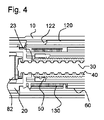
図4に図3の薬物送達デバイス100の断面をより詳細に示し、それによりばね部材130の位置を示す。ばね部材130の遠位端が内側ハウジング20に接続され、ばね部材130の近位端がインジケーション部材60に接続されている。
FIG. 4 shows in more detail a cross-section of the
図5に薬物送達デバイス100の横断面図を示す。用量設定中、用量部材70は、可動部材110、駆動部材40、およびインジケーション部材60と一緒にハウジング10に対して第1の方向に回転する。可動部材110は、用量設定中、ハウジングに対して近位にも移動するように内側ハウジング20に螺合している。インジケーション部材60がハウジングに対して回転すると、ばね部材130が付勢される。好ましくは、ばね部材130はインジケーション部材60が初期状態にあるときに既に付勢されている。
FIG. 5 shows a cross-sectional view of the
設定用量を増加させるときは、ユーザがばね部材130のトルクに打ち勝たなければならない。前記トルクは、設定動作モードにおいて用量部材70を回転させ用量を設定するときに、駆動部材40と内側ボディ20との間のスプライン状インターフェース(スプライン22および突起45を参照)による反作用を受けるはずである。前記インターフェースの配置および構成は、内側ボディ20内のスプライン22の形状が付勢されてばね部材の公称トルクを打ち消すようになっており、そのため、設定用量を変更するのに必要なトルクが、設定用量を増加させるときには正であり設定用量を減少させるときには負であるばね部材130のばね力に打ち勝つトルクと、スプライン状インターフェースを乗り越えるトルクとの計になるので、設定用量の増加および設定用量の減少に関するトルクを釣り合わせるかまたは打ち消すことができる。
When increasing the set dose, the user must overcome the torque of the
内側ボディ20のスプライン22のスプライン傾斜角度と駆動部材40上の突起45は、スプライン状インターフェースを乗り越えるのに必要なトルクが設定用量を増加させるときの方が設定用量を減少させるときより大きくなるように、用量設定中にばね部材130のばねのトルクの影響を打ち消すようにわずかにずれている。
The spline inclination angle of the
代替方法として、スプライン22と突起45との間のスプライン状インターフェースは、設定用量を増加または減少させるときに同じ過巻トルク(overwinding torque)になるように対称形に構成することができる。それにより、ばね部材は、薬物送達デバイスの設定用量を変更するために、典型的なユーザのトルクと比べてトルクが小さいと考えることができるように構成することができる。
As an alternative, the splined interface between the
図6では、図2と比較して、印66が、具体的には薬物量を示す数字が、ハウジング窓123によって表示されるように、表示部材120が示されていない。ハウジング窓123の遠位端の隣には、インジケーション部材60によって窓123を通して「0」が示されている。ハウジング窓123の近位端の隣には、インジケーション部材60によって窓123を通して「120」が示されている。数字「120」は薬物送達デバイス100の設定可能な最大の用量に関連付けることができる。
In FIG. 6, as compared with FIG. 2, the
ハウジング窓123は、ハウジング窓123を通して見ることができる印66を拡大するようにレンズ形とすることができる。ハウジング10は透明でよい。ハウジング窓123は、レンズ要素(図5の11参照)によって形成することもでき、そのレンズ要素は、ハウジング10によってユニットになるように形成することができ、ハウジング10の隆起した構造を形成する。ラベル121は、前記レンズ要素が上記で言及したラベル121の開口内に配置されるようにハウジング10に配置および貼付することができる。
The
レンズ要素11は、図6に示すように薬物送達デバイスが組み立てられたときに、インジケーション部材60のうちの印66が配置された軸方向長さ全体にわたって軸方向に延びることができる。好ましくは、表示部材120は不透明であり、そのため、薬物送達デバイスの現在の用量のインジケーションに対応していない印66が表示部材によって隠されユーザによって確認できない。
The
図7A〜図7Cに、薬物送達デバイス100の表示アセンブリの様々な状態をそれぞれ示す。図では、表示部材120は、印66が1つだけ、好ましくは(図6と比較して)現在の設定用量または投薬用量に対応する印がユーザに見えるようにしてデバイスに組み付けられている。表示部材窓122の軸方向の位置は、ハウジング窓123を通して見ることができ、デバイスの現在の用量の状態を視覚的インジケーションによりユーザに提示する。表示部材120の表面は、薬物送達デバイス100のさらなる用量情報を提示することもできる。
7A-7C illustrate various states of the display assembly of
図7Aでは、インジケーション部材60および表示部材120は初期位置にあり、ゼロ単位の用量の薬物が設定されており、そのため、表示部材窓122を通して「0」を見ることができる。表示部材窓122は開始位置にある。色つき部分64は表示部材窓122の近位側の隣に配置される。色つき部分64は赤色を含むことができる。デバイス100は、好ましくは、用量が設定されると、表示部材窓122が近位に移動し、同時に、インジケーション部材60がハウジング10に対して回転して、表示部材窓122を通して異なる印66が表示されるように構成されている。それにより、用量の量を示す数字が増大することが図7AからCに示されている。
In FIG. 7A, the
図7Bでは、薬物4単位または4つの量に相当する用量が設定され、表示部材窓122を通して「4」が表示されており、「4」は図7Aと比較してハウジングに対してわずかに近位に移動している。
In FIG. 7B, a dose corresponding to 4 units or 4 amounts of drug is set and “4” is displayed through the
図7Cでは、設定可能な最大用量の120単位の薬物が設定されている。この場合は、表示部材窓122はハウジング10に対してその最も近位の位置に、すなわち、表示部材窓122の端部の位置に配置される。さらに、表示部材窓122の遠位側の隣にハウジング窓123を通してさらなる色つき部分67が表示される。そのさらなる色つき部分67は緑色を含むことができる。
In FIG. 7C, the maximum settable dose of 120 units of drug is set. In this case, the
図8に、薬物送達デバイス100の内側の構成要素の部分縦断面図を示す。図では、駆動機構およびリターン機構を含むドライブアセンブリの構成要素が、たとえば図3より詳細に示されている。可動部材110が可動部材のねじ山125を含み、表示部材が可動部材のねじ山125と適合する表示部材のねじ山124を含むことが示されている。可動部材110はさらに、内側ハウジング20の雄ねじ山161に適合する雌ねじ山160を含む。好ましくは、ねじ山160、161のリードにより、用量設定中、用量部材がハウジングに対して遠位に移動する軸方向の距離(図9のD参照)が画成または決定される。
FIG. 8 shows a partial longitudinal cross-sectional view of the components inside
駆動部材40の突起45がさらに図8に示されている。可動部材110と内側ボディ20との間のねじ係合(ねじ山160、161参照)と、表示部材120と可動部材110との間のねじ山インターフェース(ねじ山124、125参照)との組合せにより、ハウジング10に関する表示部材120の軸方向運動が生じる。したがって、前記ねじ係合により、好ましくは、ハウジング10に対する用量部材70の対応する軸方向運動より、所与の用量設定中に実行されるハウジング10に対する表示部材120の軸方向運動を大きくすることが可能になる。
The
そのために、総距離、つまり、用量部材70が1回転に対する表示部材120の軸方向の行程は、ねじ山124およびねじ山161の螺旋ピッチの和とすることができる。
Therefore, the total distance, that is, the axial stroke of the
図9には、薬物送達デバイス100の近位端17の縦断面図が示されている。図9は、用量部材70がハウジング10に対して近位に既に有意に移動したときの、比較的大きい用量の薬物が設定された薬物送達デバイス100を示す。たとえば図8と比較して、表示部材120の近位端部が用量部材70の内側部分76に配置されている。用量を設定する間の表示部材120の軸方向の行程距離が可動部材110より大きいので、設定用量を増加させると表示部材120は次第に軸方向に用量部材70に重なる。言い換えると、用量設定中、表示部材120は内側部分76中に移動するが、構成要素は両方とも、すなわち、表示部材120も用量部材70もハウジング10に対して近位に移動する。そのために、薬物送達デバイス100の全長を増大させることなく多くの用量を設定するために表示部材120を収容する内側部分76が設けられている。
FIG. 9 shows a longitudinal cross-sectional view of the
図10A〜図10Cに薬物送達デバイス100の斜視図をそれぞれ示し、ここではハウジング10を通してインジケーション部材60を見ることができる。図10Aでは、表示部材窓122を通して「0」が見えるので用量は設定されていないことが示されている。図10Bでは、20単位の薬物用量が設定されている。図10Cでは、最大数120単位が設定されている。この実施形態では、120単位の数は設定可能な最大用量に相当するが、薬物送達デバイス100は、それより多い単位の薬物も少ない単位の薬物も設定でき薬物送達デバイス100から投薬できるように構成されている。
FIGS. 10A-10C each show a perspective view of the
図11にインジケーション部材60の斜視図を示す。印66はインジケーション部材60の外面の周りに螺旋状に配置されている。印66が0単位から120単位の薬物に及ぶことがさらに示されている。インジケーション部材60はさらに最小止め具機能68および最大止め具機能69を含み、その最小止め具機能68および最大止め具機能69は、「0」を示す印の隣および「120」を示す印の隣にそれぞれ配置されており、それにより印66の螺旋のコース(path)に隣接する。
FIG. 11 shows a perspective view of the
図12に表示部材120の斜視図を示す。インジケーション部材窓122の円周方向の隣には、最小用量止め具機能126が設けられ、好ましくは貼付されている。窓122の辺のうち最小用量止め具機能126から離れた方の辺には、最大用量止め具機能127が設けられ、好ましくは貼付されている。表示部材120はさらに突出部129を含む。突出部129の外面が、好ましくは、さらなる色つき部分67を含む。前記突出部129は、長手方向軸xに対して表示部材窓122と軸方向に位置合わせされている。
FIG. 12 shows a perspective view of the
最小用量止め具機能126は、用量が設定されていないときは、ハウジング10に対して第1の軸方向への表示部材120の軸方向運動が防止されるように、最小止め具機能68と相互作用するように配置および構成される。それにより、表示部材窓122は開始位置に配置される。
The minimum
最大用量止め具機能127は、設定できる最大用量の薬物が設定されているときは、ハウジング10に対して第1の軸方向の反対の第2の軸方向への表示部材120の軸方向運動が防止されるように最大止め具機能69と相互作用するように配置および構成される。それにより、表示部材窓122は終了位置に配置される。
The maximum
最小用量機能126は、用量が設定されていないときまたはユーザがその状態で用量を減少させようとするときに、最小止め具機能68と相互作用し、好ましくは最小止め具機能68に当接する。最大用量機能127は、設定可能な最大用量が設定されたときまたはユーザがこの状態で用量をさらに増加させようとするときに、最大止め具機能69と相互作用し、好ましくは最大止め具機能69に当接する。前記相互作用は図13に示すことができる。
The
前記止め具機能(68、69、126、127)の相対位置により、用量設定動作および/または用量投薬動作の間のインジケーション部材60の回転、ならびに表示部材120の軸方向運動が限定される。前記止め具機能(68、69、126、127)は、それぞれインジケーション部材60および表示部材120の本体から突き出た突出ボスまたは突出ショルダによって形成することができる。前記止め具機能は、薬物送達デバイス100によって設定可能な用量が、設定可能な用量の範囲に対応する表示部材60上の印66の範囲に限られるように配置および構成されている。
The relative position of the stop feature (68, 69, 126, 127) limits the rotation of the
ゼロと設定可能な最大用量との間の用量位置では、止め具機能68、69は、インジケーション部材120の長さのうち止め具機能が設けられていない部分において表示部材120の下を通る。
At dose positions between zero and the maximum settable dose, the stop features 68, 69 pass under the
表示部材120とインジケーション部材60とが直接相互作用するように前記止め具機能(68、69、126、127)を実施することによって、表示アセンブリによって表示される印66の位置合わせを簡単に制御することができる。
By performing the stop function (68, 69, 126, 127) so that the
インジケーション部材60と表示部材120との当接する部分の半径は、好ましくは、反力を低くするように大きくなっている。
The radius of the contact portion between the
薬物送達デバイス100が動作する間の表示部材120の軸方向の行程が大きくなるので、当接する部分の長さは最大限に高めることができる。
Since the stroke of the
図13A〜図13Cはさらに、インジケーション部材60と表示部材120との間の言及した止め具機能性を示す。図13Aでは、99用量単位の薬物(明確には示さない)をユーザに表示することができる。図13Bでは、119用量単位の薬物(明確には示さない)をユーザに表示することができる。図13Cでは、設定可能な最大用量120単位の薬物(明確には示さない)をユーザに表示することができる。ここでは、最大インジケーション止め具機能69は最大表示止め具機能127に当接している。
FIGS. 13A-13C further illustrate the mentioned stop functionality between the
図14では、最終用量部材50および駆動部材40の遠位の部分が側面図に示されている。最終用量部材50は最終用量止め具機能54を含む。最終用量止め具機能54は、駆動部材40の駆動部材止め具機能48と相互作用するように構成されている。最終用量部材50は駆動部材40の遠位端に螺合されている。したがって、駆動部材40は第1の雄ねじ山46を含む。駆動部材40はさらに、第2の雄ねじ山47を含む。最終用量部材50は、第1のねじ山46に適合する近位の雌ねじ山55を含む(図15参照)。さらに、最終用量部材50は、第2のねじ山47に適合する遠位の雌ねじ山56を含む(図15参照)。第2のねじ山のリードは第1のねじ山46のリードより大きい。第1のねじ山46の谷径と第2のねじ山47の谷径とは好ましくは等しい。第2のねじ山47の外径は、好ましくは、第1のねじ山46より大きい。第1および/または第2のねじ山46、47は、好ましくは、一条ねじである。
In FIG. 14, the
最終用量部材は、デバイス100が動作する間に、薬物の用量が後で設定および投薬されるときに、開始位置から終了位置まで移動するように動作可能である。開始位置は、駆動部材40の遠位端において最終用量部材50の配置に関連付けることができる。終了位置は、最終用量止め具機能54が駆動部材止め具機能48に回転方向で当接する最終用量部材50の配置に関連付けることができ、したがって、設定用量のさらなる増加が防止されるように回転止め具が形成される。
The final dose member is operable to move from a start position to an end position when a dose of drug is later set and dispensed while the
最終用量部材50はさらに、内側ハウジング20(図14に図示せず)に対して回転方向ではロックされるが、軸方向には可動である。そのために、最終用量部材50はリブ58を含み、リブ58は、駆動部材40がハウジング10に対して回転するときにハウジングのスプライン22によって軸方向にガイドされる。
The
好ましくは、用量止め具機能の軸方向に延びた部分は、第1のねじ山部のピッチまたはリードより大きく、第2のねじ山部のピッチより小さい。図14では、第2のねじ山の半回転分しか示していない。しかし、第2のねじ山のピッチは、図14に示すように、第2のねじ山47の軸方向に延びた分の2倍と判定することができる。
Preferably, the axially extending portion of the dose stop function is greater than the pitch or lead of the first thread and less than the pitch of the second thread. In FIG. 14, only the half rotation of the second thread is shown. However, as shown in FIG. 14, the pitch of the second thread can be determined to be twice that of the
図15に最終用量部材50の縦断面図を示す。最終用量部材50は凹所57を含む。遠位のねじ山55のピッチは0.7mmとすることができ、近位のねじ山56のピッチは6mmとすることができる。この実施形態によれば、カートリッジの収容力を薬物450単位と仮定すると、薬物送達デバイス100のデバイスの全長は6.5mmだけ減少させることができる。言及した数字または値は限定的なものではない。具体的には、デバイスの短縮長さは、第1のねじ山46を一条ねじとして構成することによるものである。
FIG. 15 shows a longitudinal sectional view of the
第1および第2のねじ山を設けると、言及した通り、止め具機能48および54は、より大きく、すなわち、軸方向に延びる部分がより長くなるようにして実施することができる。それにより、最終用量部材50の安定性を向上させることができる。これは、ピッチが増大すると、最終用量部材50が駆動部材40に対して近位に移動するときに、前記止め具機能をより頑強になるように実施することができることによるものである。たとえば、用量設定中に最終用量部材50が駆動部材40に対して近位に移動すると、ある点で最終用量部材は第1のねじ山46から係合解除し第2のねじ山47に係合する。
With the provision of the first and second threads, as mentioned, the stop features 48 and 54 can be implemented with larger, ie, longer axially extending portions. Thereby, the stability of the
第1のねじ山46のリードは、用量設定中にしか起こらない駆動部材40の必要な回転の大部分について最終用量部材50の軸方向の行程を制御する。好ましくは、第2のねじ山47は、用量設定中に駆動部材40の回転の最後の180度について最終用量部材50の軸方向の行程を制御する。異なる2つのねじ山の前記実施形態により、止め具機能48および54のサイズおよび強度を向上させることが可能になり、そうすることで安定性が維持される。設定用量がカートリッジ内に残る薬剤量に相当するときは、用量部材止め具機能54が、好ましくは、駆動部材止め具機能48に当接して、ユーザがより多くの用量を設定することが防止される。
The lead of the
言及した実施形態の代替方法として、駆動部材40は、言及した第1および第2のねじ山の代わりに、細目の一条ねじ(第1のねじ山46参照)のみ含むこともできる。この実施形態により、薬物送達デバイス100が動作する間に最終用量部材50の運動に必要な軸方向の空間を有意に減少させることが可能になる。このように減少させると、デバイスの全長をより短くするか、またはより収容力の大きい薬物カートリッジの収容を容易にすることが可能になる。
As an alternative to the mentioned embodiment, the
用量を投薬する間には、インジケーション部材60、可動部材110および表示部材120の運動に関与または起因する摩擦に打ち勝つのに必要なエネルギーは、好ましくは、リターン機構によって、具体的には付勢された駆動ばねによって消費される。さらに、投薬クリッカ機構から生じる摩擦は、上記で言及したように、リターン機構によってもたらされる。ボタン70および可動部材110を含む投薬クリッカ機構は、用量投薬中アクティブである。投薬クリッカ機構は、主に、薬物が投薬されているという可聴式フィードバックをユーザに与える。可動部材110上の可撓性のアーム65とボタン70上の歯状のプロフィルとの相互作用により、このような投薬のクリック感が与えられる。相対的な回転は一方向にのみ可能である。これは投薬中に可動部材110とボタン70とがデカップリングするときに起き、薬物1単位につき1回クリック感が発生する。
During dispensing, the energy required to overcome the friction involved or caused by the movement of the
ばね部材130によって及ぼされるかまたはばね部材130を付勢するのに必要なトルクは、好ましくは低く、すなわち0.5から2Nmmの範囲にある。前記トルクは、ゼロ用量の位置で必要であり、用量設定中にばね部材130が巻かれるにつれてトルクはたとえば最大トルク5Nmmまで増大する。ばね部材130によって及ぼされるトルクは、好ましくは、たとえばある用量の薬物設定中、ユーザが拡大しなければならない設定するためのトルクに最小限の影響しか有しないように選択される。
The torque exerted by or required to bias the
リターン機構が設けられていない同等の実施形態と比較すると、リターン機構を設けることによって、内側ボディ20と可動部材110(ねじ山160、161)との間のねじ山インターフェースの螺旋ピッチを35%だけ減少させることができる。そのために、所与の用量位置のためのまたは所与の用量を設定するための可動部材110の軸方向の行程は同様に35%だけ減少する。
Compared to an equivalent embodiment in which no return mechanism is provided, by providing a return mechanism, the helical pitch of the thread interface between the
可動部材110の軸方向の行程が言及したように減少すると、隣接する印66間の軸方向のピッチを約4.3mmに減少させることができる。このピッチは、当技術分野の表示アセンブリ、具体的には、3桁、すなわち、100単位超の薬物を必要とすることがある設定用量の大きい場合に、簡単に判読可能な状態にするのに不十分であると考えられる。したがって、本開示は、用量設定中に内側部分が表示部材120の近位端を収容する、用量部材70の内側部分76に関して上記で言及した機能性を提供する。
If the axial travel of the
用量を投薬する間にユーザによって加えられる軸方向の力は、用量を投薬する間に表示部材120、インジケーション部材60および可動部材110を戻すのに一部たりとも使用する必要がないので、ねじ山160、161の螺旋ピッチを減少させることは上記で言及したリターン機構によって容易になる。インジケーション部材60および可動部材110を戻す、すなわち回転させるにはトルクを加えなければならない。リターン機構なしの現行のデバイスでは、このトルクは、ユーザがねじ山インターフェース160、161を追い抜くまたは乗り越えることによって加えられる軸方向の力の一部によって発生する。前記インターフェースを乗り越えるためには、そのリード角は摩擦力に打ち勝つのに十分に大きくなければならない。これは、具体的にはこのねじ山インターフェースにおける摩擦に対するデバイスの影響の受け易さを考慮すると、ねじ山インターフェースのピッチを減少させる範囲を限定する。
Since the axial force applied by the user during dose dispensing need not be used in part to return the
したがって、リターン機構を含む所与のドライブアセンブリでは、駆動機構はねじ山インターフェースにおける摩擦損失の影響を有意に受けにくくなるかまたはそれに左右されにくくなる。 Thus, for a given drive assembly that includes a return mechanism, the drive mechanism is significantly less susceptible to or susceptible to frictional losses at the thread interface.
可動部材110の軸方向の行程を減少させることによって、具体的には設定用量が大きい場合または指の運動が制限されたユーザの場合に、薬物送達デバイス100の人間工学的な動作または設計も改善される。たとえば最大用量の薬物が設定されたときに、可動部材110の前記軸方向の行程の距離(図2のD参照)を減少させると、ピストンロッド30および内側ボディ20の長さの減少も可能にし、これはデバイスの全長を短縮することを可能にする。
Reducing the axial travel of the
ある用量を投薬する間にばね部材130によってもたらされるトルクは、具体的には、インジケーション部材60を介して可動部材110を回転させかつ/または戻し、それにより、表示部材120を戻しかつ/または遠位に移動させるのに十分である。可動部材110と用量部材70との間に設けられた投薬クリッカを乗り越えるのにも十分である。残るトルクがあればそれが可動部材110と内側ハウジング20との間のねじ山インターフェースに加えられ、可動部材110と駆動部材40との間の軸方向の連結部において軸方向の小さい力を発生させる。したがって、ばね部材130は、ある用量の薬物が投薬されるときに、駆動部材40に軸方向の補助的な小さい力をもたらすことができる。
The torque provided by the
デバイス100を使用するために、ユーザが用量部材70を第1の方向に回転させることによって用量を選択しなければならない。設定動作モードでは用量部材70が可動部材110に対して回転方向でロックされるので、可動部材110と内側ハウジング20との間のねじ係合によってデバイス100の外で用量部材70を巻く。さらに、単位数は段階的に計数され、やはりハウジングに対して近位に移動する表示部材窓122を通して表示される。ボタン70が第1の方向に回転するとドライバ40が回転し、そうするとドライバ40はピストンロッド30に沿って前進する。ピストンロッド30はダイヤルを回す間はずっと固定された状態にある。設定可能な最大用量では、図11および図12に示す止め具機能69、127は互いに当接してさらなる用量の増加を防止する。
To use the
最終用量部材またはナット50は投薬単位の総数を計数するという役割を実行する。ナット50は、使用終了時にデバイス100をロックし、したがって、より多くの用量の薬物にダイヤルを回すかまたはそれを設定することができない。最終用量ナット50とドライバ40とは、上記で説明した通り、互いに対してねじ係合している。さらに、最終用量ナット50は図8に示すようにスプライン22に組み付けられて、ナット50と内側ボディ20とは(常時)一緒になって回転方向でロックされる。ダイヤルを回す間に用量部材が回転することによってインジケーション部材60が回転するとばね部材130が付勢される。さらに、ピストンロッドが回転すると、ナット50がドライバ40に沿って前進する。ナット50は、内側ボディ20内を常時軸方向に自由に摺動し、これはナット50の前進を可能にする。図14および図15に示すねじ山(46、47、55、56参照)が最終用量に向かって軸方向に変化すると、使用終了の閉鎖状況に向かってナット50の前進が加速する。使用終了状況では最終用量ナット50の止め具機能54はドライバ40上の対応する機能48に接触する。スプラインによる内側ボディ20との接触部はこの止め具機能48に伝達されるトルクがあればそれに反応する。
The final dose member or
所望の用量にダイヤルを回すと、デバイス100は用量を投薬する準備ができる。これは、基本的にボタン70を遠位に押すことを必要とし、これによりクラッチまたはロッキング歯74、114が係合解除する。上記で言及したように、ある用量にダイヤルを回すと、ボタン70は「外向きに付勢され」、ボタン70に対して可動部材110を回転方向でロックするロッキング歯74、114は互いに係合する。ボタン70を押す時に、ロッキング歯74、114は互いに係合解除し、可動部材110とボタン70との間の相対的な回転が可能になる(図3および図8参照)。どの条件でも、ドライバ40とボタン70とは係合によって一緒になるように回転方向でロックされる。同時に、ドライバ40に対してボタン70が相対的に軸方向運動すると、ポケットまたは凹所73が突起45に関してずれる。したがって、突起45は、突起45がボタン70の凹所になっていない領域(凹所73参照)に載るので内側に曲がることが防止される。この条件では、ドライバ40およびボタン70は、内側ボディ20に回転方向で拘束され、したがって、ハウジング10に関してどの回転も防止される。
When the dial is turned to the desired dose,
所望の用量にダイヤルを回すと、ボタン70はユーザによって手で押し下げて駆動機構を駆動してある用量を投薬させることができ、ピストンロッド30は前方に押しやられてカートリッジ80から薬物が投薬される。それにより、ユーザによって加えられた駆動力は、駆動機構を介してピストンロッドに伝達されて、ハウジング10に対して遠位方向にピストンロッド30を押しやる。
When the dial is turned to the desired dose, the
ピストンロッド30、ドライバ40および可動部材110と内側ハウジング20との間の嵌合するねじ山の相互作用により、メカニカルアドバンテージを2:1または3:1にすることができる。
The mechanical advantage can be 2: 1 or 3: 1 due to the interaction of the
ボタン70が押され、デバイスが投薬動作モードにあるときは、付勢されたばね部材130のエネルギーを用いてリターン機構を駆動し、可動部材110はハウジングに対してその初期位置に向かって第2の方向に戻るように回転する。上記で言及した投薬クリッカ機構もまたばね部材130によって駆動する。具体的には、ばね部材130は、第2の方向にハウジングに対してその初期位置に向かってインジケーション部材60を回転させ、インジケーション部材60はスプライン128、131によって可動部材に対して回転方向でロックされる。表示部材120が可動部材110に螺合しているので、表示部材窓122も軸方向に戻されるかまたは後退し、それにより、投薬動作中の実際の用量情報を即座に示す。
When the
好ましくは、ばね部材130のばね力は、ある用量の薬物が投薬されるように投薬動作モードでデバイスを動作させるのに必要な駆動力より小さい。
Preferably, the spring force of the
明確に記載していないが薬物送達デバイス100の提示した概念では、薬物送達デバイス100のプライミングの必要を無くした機構を用いることもできる。
Although not explicitly described, the proposed concept of
保護範囲は本明細書で上記に与えられたものに限定されない。本発明は、請求項または実施例でこの特性またはこの特性の組合せが明確に述べられていなくても、具体的には、請求項で述べる任意の特性の組合せをすべて含む新規の各特徴および特徴の各組合せで実施される。 The protection scope is not limited to that given herein above. The invention includes each and every novel feature and feature specifically including any combination of the features recited in the claims, even if the feature or combination of features is not explicitly stated in the claims or examples. It is carried out in each combination.
10 ハウジング
11 レンズ要素
16 遠位端
17 近位端
20 内側ハウジング、内側ボディ
22 スプライン(内側ボディ)
23 雌ねじ山(内側ボディ)
30 ピストンロッド
31 支承部
40 駆動部材、ドライバ
44 弾性のフィンガ
45 突起
46 第1のねじ山(用量部材)
47 第2のねじ山(用量部材)
48 駆動部材止め具機能
50 ナット、最終用量部材
54 最終用量止め具機能
55 近位のねじ山(最終用量部材)
56 遠位のねじ山(最終用量部材)
57 凹所(最終用量部材)
58 リブ(最終用量部材)
60 インジケーション部材
64 色つき部分
65 可撓性のアーム
66 印
67 さらなる色つき部分
68 最小止め具機能(インジケーション部材)
69 最大止め具機能(インジケーション部材)
70 用量部材、ボタン
72 スリーブ様の部分
73 凹所(用量部材)
74 ロッキング歯(用量部材)
76 内側部分
80 カートリッジ
81 カートリッジリザーバ
82 ピストン、栓
83 金属バンド
100 薬物送達デバイス
110 可動部材
114 ロッキング歯(可動部材)
120 表示部材
121 ラベル
122 表示部材窓
123 ハウジング窓
124 表示部材のねじ山
125 可動部材のねじ山
126 最小用量止め具機能
127 最大用量止め具機能
128 可動部材のスプライン
129 突出部
130 ばね部材
131 インジケーション部材のスプライン
160 雌ねじ山(可動部材)
161 雄ねじ山(内側ボディ)
X 長手方向軸
D 軸方向の距離
DESCRIPTION OF
23 Female thread (inner body)
30
47 Second Thread (Dose Member)
48 Drive
56 Distal Thread (Final Dose Member)
57 recess (final dose member)
58 ribs (final dose member)
60
69 Maximum stop function (indication member)
70 dose member,
74 Locking teeth (dose member)
76
120
161 Male thread (inner body)
X Longitudinal axis D Axial distance
Claims (16)
近位端(17)、遠位端(16)および長手方向軸(x)を有するハウジング(10)と、
表示部材窓(122)を画成し、ハウジング(10)に対して回転方向でロックされるが長手方向軸(x)に沿って移動可能である表示部材(120)と、
印(66)を含むインジケーション部材(60)と、
該インジケーション部材(60)に回転方向でロックされ、さらに表示部材(120)に連結されハウジング(10)に対して回転可能である可動部材(110)と
を含み、
ここで、該可動部材(110)がハウジング(10)に対して回転されたとき、回転する可動部材(110)がハウジング(10)に対して軸方向に表示部材(120)を移動させて、表示部材窓(122)を通して様々な印(66)を表示するように構成されており、
ここで、該可動部材(110)は可動部材のねじ山(125)を含み、該表示部材(120)は表示部材のねじ山(124)を含み、そして該可動部材のねじ山(125)は該表示部材のねじ山(124)とねじ係合する、
前記表示アセンブリ。 A display assembly for a drug delivery device (100) comprising:
A housing (10) having a proximal end (17), a distal end (16) and a longitudinal axis (x);
A display member (120) defining a display member window (122) and locked in rotation with respect to the housing (10) but movable along the longitudinal axis (x);
An indication member (60) including indicia (66);
A movable member (110) that is locked to the indication member (60) in the rotational direction, and that is connected to the display member (120) and is rotatable with respect to the housing (10);
Here, when the movable member (110) is rotated with respect to the housing (10), the rotating movable member (110) moves the display member (120) in the axial direction with respect to the housing (10), and is configured to display various indicia (66) through the display element window (122),
Here, the movable member (110) includes a thread (125) of the movable member, the indicator member (120) includes a thread (124) of the indicator member, and the thread (125) of the movable member is Threadedly engaging the thread (124) of the indicating member;
Said display assembly.
近位端(17)、遠位端(16)および長手方向軸(x)を有するハウジング(10)と、 A housing (10) having a proximal end (17), a distal end (16) and a longitudinal axis (x);
表示部材窓(122)を画成し、ハウジング(10)に対して回転方向でロックされるが長手方向軸(x)に沿って移動可能である表示部材(120)と、 A display member (120) defining a display member window (122) and locked in rotation with respect to the housing (10) but movable along the longitudinal axis (x);
印(66)を含むインジケーション部材(60)と、 An indication member (60) including indicia (66);
該インジケーション部材(60)に回転方向でロックされ、さらに表示部材(120)に連結されハウジング(10)に対して回転可能である可動部材(110)と A movable member (110) which is locked to the indication member (60) in the rotational direction, and is connected to the display member (120) and is rotatable with respect to the housing (10);
を含み、Including
ここで、該可動部材(110)がハウジング(10)に対して回転されたとき、回転する可動部材(110)がハウジング(10)に対して軸方向に表示部材(120)を移動させて、表示部材窓(122)を通して様々な印(66)を表示するように構成されており、 Here, when the movable member (110) is rotated with respect to the housing (10), the rotating movable member (110) moves the display member (120) in the axial direction with respect to the housing (10), and Configured to display various indicia (66) through the display member window (122);
ここで、可動部材(110)はハウジング(10)とねじ係合する、 Here, the movable member (110) is screw-engaged with the housing (10).
前記表示アセンブリ。Said display assembly.
近位端(17)、遠位端(16)および長手方向軸(x)を有するハウジング(10)と、 A housing (10) having a proximal end (17), a distal end (16) and a longitudinal axis (x);
表示部材窓(122)を画成し、ハウジング(10)に対して回転方向でロックされるが長手方向軸(x)に沿って移動可能である表示部材(120)と、 A display member (120) defining a display member window (122) and locked in rotation with respect to the housing (10) but movable along the longitudinal axis (x);
印(66)を含むインジケーション部材(60)と、 An indication member (60) including indicia (66);
該インジケーション部材(60)に回転方向でロックされ、さらに表示部材(120)に連結されハウジング(10)に対して回転可能である可動部材(110)と A movable member (110) which is locked to the indication member (60) in the rotational direction, and is connected to the display member (120) and is rotatable with respect to the housing (10);
を含み、Including
ここで、該可動部材(110)がハウジング(10)に対して回転されたとき、回転する可動部材(110)がハウジング(10)に対して軸方向に表示部材(120)を移動させて、表示部材窓(122)を通して様々な印(66)を表示するように構成されており、 Here, when the movable member (110) is rotated with respect to the housing (10), the rotating movable member (110) moves the display member (120) in the axial direction with respect to the housing (10), and Configured to display various indicia (66) through the display member window (122);
ここで、該表示アセンブリは、表示アセンブリの動作中、可動部材(110)がハウジング(10)に対して軸方向に移動するときに、表示部材(120)の移動する軸方向の距離が可動部材(110)の移動する軸方向の距離より大きくなるように構成されている、 Here, when the movable member (110) moves in the axial direction with respect to the housing (10) during operation of the display assembly, the display assembly (120) moves in the axial distance. (110) configured to be larger than the moving axial distance.
前記表示アセンブリ。Said display assembly.
近位端(17)、遠位端(16)および長手方向軸(x)を有するハウジング(10)と、 A housing (10) having a proximal end (17), a distal end (16) and a longitudinal axis (x);
表示部材窓(122)を画成し、ハウジング(10)に対して回転方向でロックされるが長手方向軸(x)に沿って移動可能である表示部材(120)と、 A display member (120) defining a display member window (122) and locked in rotation with respect to the housing (10) but movable along the longitudinal axis (x);
印(66)を含むインジケーション部材(60)と、 An indication member (60) including indicia (66);
該インジケーション部材(60)に回転方向でロックされ、さらに表示部材(120)に連結されハウジング(10)に対して回転可能である可動部材(110)と A movable member (110) which is locked to the indication member (60) in the rotational direction, and is connected to the display member (120) and is rotatable with respect to the housing (10);
を含み、Including
ここで、該可動部材(110)がハウジング(10)に対して回転されたとき、回転す Here, when the movable member (110) is rotated with respect to the housing (10), it rotates.
る可動部材(110)がハウジング(10)に対して軸方向に表示部材(120)を移動させて、表示部材窓(122)を通して様々な印(66)を表示するように構成されており、A movable member (110) configured to move the display member (120) axially relative to the housing (10) to display various marks (66) through the display member window (122);
該表示アセンブリは、ハウジング(10)およびインジケーション部材(60)に連結されたばね部材(130)をさらに含み、ここで、表示アセンブリは、用量が設定されるとインジケーション部材(60)が初期位置から用量設定位置に回転し、それにより、ばね部材(130)が付勢され、用量が投薬されるとばね部材(130)がインジケーション部材(60)の初期位置に向かってインジケーション部材(60)を移動させるように構成されている、 The display assembly further includes a spring member (130) coupled to the housing (10) and the indication member (60), wherein the display assembly is configured so that the indication member (60) is in an initial position when a dose is set. To the dose setting position, whereby the spring member (130) is biased and when the dose is dispensed, the spring member (130) moves toward the initial position of the indication member (60). ) Is configured to move,
前記表示アセンブリ。Said display assembly.
Applications Claiming Priority (3)
| Application Number | Priority Date | Filing Date | Title |
|---|---|---|---|
| EP13163104.6 | 2013-04-10 | ||
| EP13163104 | 2013-04-10 | ||
| PCT/EP2014/056997 WO2014166915A1 (en) | 2013-04-10 | 2014-04-08 | Display assembly for a drug delivery device |
Publications (2)
| Publication Number | Publication Date |
|---|---|
| JP2016514601A JP2016514601A (en) | 2016-05-23 |
| JP6422943B2 true JP6422943B2 (en) | 2018-11-14 |
Family
ID=48083025
Family Applications (1)
| Application Number | Title | Priority Date | Filing Date |
|---|---|---|---|
| JP2016506899A Expired - Fee Related JP6422943B2 (en) | 2013-04-10 | 2014-04-08 | Display assembly for a drug delivery device |
Country Status (9)
| Country | Link |
|---|---|
| US (1) | US9950120B2 (en) |
| EP (1) | EP2983764B1 (en) |
| JP (1) | JP6422943B2 (en) |
| CN (1) | CN105263547B (en) |
| AR (1) | AR095806A1 (en) |
| DK (1) | DK2983764T3 (en) |
| HK (1) | HK1215202A1 (en) |
| TW (1) | TW201509465A (en) |
| WO (1) | WO2014166915A1 (en) |
Families Citing this family (9)
| Publication number | Priority date | Publication date | Assignee | Title |
|---|---|---|---|---|
| US10322242B2 (en) * | 2013-09-03 | 2019-06-18 | Sanofi | Mechanism for a drug delivery device and drug delivery device comprising the mechanism |
| WO2017114911A1 (en) | 2015-12-30 | 2017-07-06 | Ascendis Pharma A/S | Auto injector with detection of used cartridge and associated method |
| SI3397321T1 (en) | 2015-12-30 | 2023-02-28 | Ascendis Pharma A/S | Auto injector with temperature control |
| EP3912660A1 (en) | 2015-12-30 | 2021-11-24 | Ascendis Pharma A/S | Auto injector with adaptable air-shot mechanism |
| US11406760B2 (en) | 2015-12-30 | 2022-08-09 | Ascendis Pharma A/S | Auto injector with charger safety |
| EP3397324B1 (en) * | 2015-12-30 | 2022-07-06 | Ascendis Pharma A/S | Auto injector with cartridge retention system |
| BR112019024511A2 (en) | 2017-05-23 | 2020-06-23 | Ascendis Pharma A/S | AUTOINJECTOR FOR THE ADMINISTRATION OF A MEDICINE, SYSTEM, AND METHOD TO CONTROL AN AUTOINJECTOR. |
| RU2762331C2 (en) | 2017-06-29 | 2021-12-17 | Ассендис Фарма А/С | Automatic injector with support for drug recovery manipulations |
| JP2021524299A (en) * | 2018-05-17 | 2021-09-13 | サノフイSanofi | Touch-sensitive label for injection devices |
Family Cites Families (16)
| Publication number | Priority date | Publication date | Assignee | Title |
|---|---|---|---|---|
| DE29703820U1 (en) * | 1997-03-03 | 1998-07-02 | Medico Dev Investment Co | Injection device |
| US5961495A (en) * | 1998-02-20 | 1999-10-05 | Becton, Dickinson And Company | Medication delivery pen having a priming mechanism |
| CN101039713B (en) * | 2004-10-14 | 2011-10-12 | 诺和诺德公司 | Syringe with dosis mechanism |
| US9101722B2 (en) * | 2005-02-28 | 2015-08-11 | Novo Nordisk A/S | Dose setting mechanism for an injection device capable of presetting a maximum dose |
| EP1923085A1 (en) | 2006-11-17 | 2008-05-21 | Sanofi-Aventis Deutschland GmbH | Dosing and drive mechanism for drug delivery device |
| DE102007026083A1 (en) * | 2007-05-25 | 2008-11-27 | Haselmeier S.A.R.L. | injection device |
| DK2285438T3 (en) * | 2008-06-05 | 2015-10-12 | Shl Group Ab | Drug delivery device |
| DE202008011175U1 (en) * | 2008-08-18 | 2010-01-07 | Haselmeier Gmbh | injection device |
| WO2010112558A1 (en) * | 2009-03-31 | 2010-10-07 | Sanofi-Aventis Deutschland Gmbh | Drug delivery device with dose indication window |
| US9125994B2 (en) * | 2009-06-01 | 2015-09-08 | Sanofi—Aventis Deutschland GmbH | Drug delivery device with dose dial sleeve rotational stop |
| EP2482874A4 (en) * | 2009-09-30 | 2014-11-26 | Shl Group Ab | Medicament delivery device |
| WO2011067267A1 (en) * | 2009-12-02 | 2011-06-09 | Sanofi-Aventis Deutschland Gmbh | Dose display mechanism for a drug delivery device |
| AU2011315628B2 (en) * | 2010-10-13 | 2015-05-07 | Sanofi-Aventis Deutschland Gmbh | Dose setting mechanism |
| MX2015014293A (en) * | 2013-04-10 | 2015-12-08 | Sanofi Sa | Injection device. |
| EP2983761B1 (en) * | 2013-04-10 | 2017-11-15 | Sanofi | Drive assembly for a drug delivery device |
| US10092705B2 (en) * | 2013-04-10 | 2018-10-09 | Sanofi | Injection device |
-
2014
- 2014-04-08 DK DK14716554.2T patent/DK2983764T3/en active
- 2014-04-08 JP JP2016506899A patent/JP6422943B2/en not_active Expired - Fee Related
- 2014-04-08 WO PCT/EP2014/056997 patent/WO2014166915A1/en active Application Filing
- 2014-04-08 TW TW103112788A patent/TW201509465A/en unknown
- 2014-04-08 EP EP14716554.2A patent/EP2983764B1/en not_active Not-in-force
- 2014-04-08 CN CN201480020743.3A patent/CN105263547B/en not_active Expired - Fee Related
- 2014-04-08 US US14/782,676 patent/US9950120B2/en not_active Expired - Fee Related
- 2014-04-08 AR ARP140101521A patent/AR095806A1/en unknown
-
2016
- 2016-03-17 HK HK16103139.8A patent/HK1215202A1/en not_active IP Right Cessation
Also Published As
| Publication number | Publication date |
|---|---|
| AR095806A1 (en) | 2015-11-11 |
| CN105263547B (en) | 2019-06-28 |
| EP2983764A1 (en) | 2016-02-17 |
| TW201509465A (en) | 2015-03-16 |
| EP2983764B1 (en) | 2017-08-02 |
| CN105263547A (en) | 2016-01-20 |
| US9950120B2 (en) | 2018-04-24 |
| DK2983764T3 (en) | 2017-11-13 |
| JP2016514601A (en) | 2016-05-23 |
| WO2014166915A1 (en) | 2014-10-16 |
| US20160067408A1 (en) | 2016-03-10 |
| HK1215202A1 (en) | 2016-08-19 |
Similar Documents
| Publication | Publication Date | Title |
|---|---|---|
| JP6417393B2 (en) | Drive assembly for a drug delivery device | |
| JP6314140B2 (en) | Drug delivery device | |
| JP6422943B2 (en) | Display assembly for a drug delivery device | |
| JP6359635B2 (en) | Injection device | |
| JP6567522B2 (en) | Mechanism for drug delivery device and drug delivery device including mechanism | |
| JP6419159B2 (en) | Injection device | |
| JP6404323B2 (en) | Injection device | |
| JP6695333B2 (en) | Drug injection device with resettable mechanism that allows piston rod to retract when changing drug cartridge | |
| JP6395809B2 (en) | Injection device | |
| JP2017534363A (en) | Drug delivery device | |
| JP6466945B2 (en) | Drive assembly for drug delivery device and drug delivery device including drive assembly | |
| JP6395808B2 (en) | Injection device | |
| JP2017520374A (en) | Drug delivery device | |
| JP2016529013A (en) | Housing and cap for injection devices made of outer metal member and inner plastic member | |
| JP2018505026A (en) | Drive mechanism for injection device | |
| JP2017530798A (en) | Housing and drug delivery device having housing | |
| JP2017534364A (en) | Housing, drug delivery device having housing, and method of manufacturing housing | |
| JP2017520368A (en) | An injection device including a compression spring for engaging the ratchet element, urging the actuation button, and urging the locking element into the dose setting mode | |
| JP6722180B2 (en) | Drug delivery device | |
| JP2016514599A (en) | Injection device | |
| JP6717822B2 (en) | Display and drug delivery device having a display | |
| JP6499659B2 (en) | Assembly for a drug delivery device | |
| JP2016514586A (en) | Pen-type drug injection device and dose setting limiter mechanism therefor | |
| JP6480924B2 (en) | Drug delivery device | |
| JP6637974B2 (en) | Dose dosing assembly for drug delivery device with different leads and multiple thread sections |
Legal Events
| Date | Code | Title | Description |
|---|---|---|---|
| A621 | Written request for application examination |
Free format text: JAPANESE INTERMEDIATE CODE: A621 Effective date: 20170329 |
|
| A977 | Report on retrieval |
Free format text: JAPANESE INTERMEDIATE CODE: A971007 Effective date: 20180215 |
|
| A131 | Notification of reasons for refusal |
Free format text: JAPANESE INTERMEDIATE CODE: A131 Effective date: 20180227 |
|
| A521 | Request for written amendment filed |
Free format text: JAPANESE INTERMEDIATE CODE: A523 Effective date: 20180524 |
|
| TRDD | Decision of grant or rejection written | ||
| A01 | Written decision to grant a patent or to grant a registration (utility model) |
Free format text: JAPANESE INTERMEDIATE CODE: A01 Effective date: 20180925 |
|
| A61 | First payment of annual fees (during grant procedure) |
Free format text: JAPANESE INTERMEDIATE CODE: A61 Effective date: 20181017 |
|
| R150 | Certificate of patent or registration of utility model |
Ref document number: 6422943 Country of ref document: JP Free format text: JAPANESE INTERMEDIATE CODE: R150 |
|
| LAPS | Cancellation because of no payment of annual fees |