JP6359635B2 - Injection device - Google Patents
Injection device Download PDFInfo
- Publication number
- JP6359635B2 JP6359635B2 JP2016506892A JP2016506892A JP6359635B2 JP 6359635 B2 JP6359635 B2 JP 6359635B2 JP 2016506892 A JP2016506892 A JP 2016506892A JP 2016506892 A JP2016506892 A JP 2016506892A JP 6359635 B2 JP6359635 B2 JP 6359635B2
- Authority
- JP
- Japan
- Prior art keywords
- dose
- housing
- indicator
- injection device
- driver
- Prior art date
- Legal status (The legal status is an assumption and is not a legal conclusion. Google has not performed a legal analysis and makes no representation as to the accuracy of the status listed.)
- Active
Links
Images


Classifications
-
- A—HUMAN NECESSITIES
- A61—MEDICAL OR VETERINARY SCIENCE; HYGIENE
- A61M—DEVICES FOR INTRODUCING MEDIA INTO, OR ONTO, THE BODY; DEVICES FOR TRANSDUCING BODY MEDIA OR FOR TAKING MEDIA FROM THE BODY; DEVICES FOR PRODUCING OR ENDING SLEEP OR STUPOR
- A61M5/00—Devices for bringing media into the body in a subcutaneous, intra-vascular or intramuscular way; Accessories therefor, e.g. filling or cleaning devices, arm-rests
- A61M5/178—Syringes
- A61M5/31—Details
- A61M5/315—Pistons; Piston-rods; Guiding, blocking or restricting the movement of the rod or piston; Appliances on the rod for facilitating dosing ; Dosing mechanisms
- A61M5/31565—Administration mechanisms, i.e. constructional features, modes of administering a dose
- A61M5/31576—Constructional features or modes of drive mechanisms for piston rods
- A61M5/31583—Constructional features or modes of drive mechanisms for piston rods based on rotational translation, i.e. movement of piston rod is caused by relative rotation between the user activated actuator and the piston rod
- A61M5/31586—Constructional features or modes of drive mechanisms for piston rods based on rotational translation, i.e. movement of piston rod is caused by relative rotation between the user activated actuator and the piston rod performed by rotationally moving or pivoted actuator, e.g. an injection lever or handle
-
- A—HUMAN NECESSITIES
- A61—MEDICAL OR VETERINARY SCIENCE; HYGIENE
- A61M—DEVICES FOR INTRODUCING MEDIA INTO, OR ONTO, THE BODY; DEVICES FOR TRANSDUCING BODY MEDIA OR FOR TAKING MEDIA FROM THE BODY; DEVICES FOR PRODUCING OR ENDING SLEEP OR STUPOR
- A61M5/00—Devices for bringing media into the body in a subcutaneous, intra-vascular or intramuscular way; Accessories therefor, e.g. filling or cleaning devices, arm-rests
- A61M5/178—Syringes
- A61M5/20—Automatic syringes, e.g. with automatically actuated piston rod, with automatic needle injection, filling automatically
-
- A—HUMAN NECESSITIES
- A61—MEDICAL OR VETERINARY SCIENCE; HYGIENE
- A61M—DEVICES FOR INTRODUCING MEDIA INTO, OR ONTO, THE BODY; DEVICES FOR TRANSDUCING BODY MEDIA OR FOR TAKING MEDIA FROM THE BODY; DEVICES FOR PRODUCING OR ENDING SLEEP OR STUPOR
- A61M5/00—Devices for bringing media into the body in a subcutaneous, intra-vascular or intramuscular way; Accessories therefor, e.g. filling or cleaning devices, arm-rests
- A61M5/178—Syringes
- A61M5/31—Details
- A61M5/315—Pistons; Piston-rods; Guiding, blocking or restricting the movement of the rod or piston; Appliances on the rod for facilitating dosing ; Dosing mechanisms
- A61M5/31511—Piston or piston-rod constructions, e.g. connection of piston with piston-rod
-
- A—HUMAN NECESSITIES
- A61—MEDICAL OR VETERINARY SCIENCE; HYGIENE
- A61M—DEVICES FOR INTRODUCING MEDIA INTO, OR ONTO, THE BODY; DEVICES FOR TRANSDUCING BODY MEDIA OR FOR TAKING MEDIA FROM THE BODY; DEVICES FOR PRODUCING OR ENDING SLEEP OR STUPOR
- A61M5/00—Devices for bringing media into the body in a subcutaneous, intra-vascular or intramuscular way; Accessories therefor, e.g. filling or cleaning devices, arm-rests
- A61M5/178—Syringes
- A61M5/31—Details
- A61M5/315—Pistons; Piston-rods; Guiding, blocking or restricting the movement of the rod or piston; Appliances on the rod for facilitating dosing ; Dosing mechanisms
- A61M5/31533—Dosing mechanisms, i.e. setting a dose
- A61M5/31535—Means improving security or handling thereof, e.g. blocking means, means preventing insufficient dosing, means allowing correction of overset dose
- A61M5/31541—Means preventing setting of a dose beyond the amount remaining in the cartridge
-
- A—HUMAN NECESSITIES
- A61—MEDICAL OR VETERINARY SCIENCE; HYGIENE
- A61M—DEVICES FOR INTRODUCING MEDIA INTO, OR ONTO, THE BODY; DEVICES FOR TRANSDUCING BODY MEDIA OR FOR TAKING MEDIA FROM THE BODY; DEVICES FOR PRODUCING OR ENDING SLEEP OR STUPOR
- A61M5/00—Devices for bringing media into the body in a subcutaneous, intra-vascular or intramuscular way; Accessories therefor, e.g. filling or cleaning devices, arm-rests
- A61M5/178—Syringes
- A61M5/31—Details
- A61M5/315—Pistons; Piston-rods; Guiding, blocking or restricting the movement of the rod or piston; Appliances on the rod for facilitating dosing ; Dosing mechanisms
- A61M5/31533—Dosing mechanisms, i.e. setting a dose
- A61M5/31545—Setting modes for dosing
- A61M5/31548—Mechanically operated dose setting member
- A61M5/3155—Mechanically operated dose setting member by rotational movement of dose setting member, e.g. during setting or filling of a syringe
- A61M5/31553—Mechanically operated dose setting member by rotational movement of dose setting member, e.g. during setting or filling of a syringe without axial movement of dose setting member
-
- A—HUMAN NECESSITIES
- A61—MEDICAL OR VETERINARY SCIENCE; HYGIENE
- A61M—DEVICES FOR INTRODUCING MEDIA INTO, OR ONTO, THE BODY; DEVICES FOR TRANSDUCING BODY MEDIA OR FOR TAKING MEDIA FROM THE BODY; DEVICES FOR PRODUCING OR ENDING SLEEP OR STUPOR
- A61M5/00—Devices for bringing media into the body in a subcutaneous, intra-vascular or intramuscular way; Accessories therefor, e.g. filling or cleaning devices, arm-rests
- A61M5/178—Syringes
- A61M5/31—Details
- A61M5/315—Pistons; Piston-rods; Guiding, blocking or restricting the movement of the rod or piston; Appliances on the rod for facilitating dosing ; Dosing mechanisms
- A61M5/31565—Administration mechanisms, i.e. constructional features, modes of administering a dose
- A61M5/31566—Means improving security or handling thereof
- A61M5/3157—Means providing feedback signals when administration is completed
-
- A—HUMAN NECESSITIES
- A61—MEDICAL OR VETERINARY SCIENCE; HYGIENE
- A61M—DEVICES FOR INTRODUCING MEDIA INTO, OR ONTO, THE BODY; DEVICES FOR TRANSDUCING BODY MEDIA OR FOR TAKING MEDIA FROM THE BODY; DEVICES FOR PRODUCING OR ENDING SLEEP OR STUPOR
- A61M5/00—Devices for bringing media into the body in a subcutaneous, intra-vascular or intramuscular way; Accessories therefor, e.g. filling or cleaning devices, arm-rests
- A61M5/178—Syringes
- A61M5/31—Details
- A61M5/315—Pistons; Piston-rods; Guiding, blocking or restricting the movement of the rod or piston; Appliances on the rod for facilitating dosing ; Dosing mechanisms
- A61M5/31565—Administration mechanisms, i.e. constructional features, modes of administering a dose
- A61M5/31576—Constructional features or modes of drive mechanisms for piston rods
- A61M5/31583—Constructional features or modes of drive mechanisms for piston rods based on rotational translation, i.e. movement of piston rod is caused by relative rotation between the user activated actuator and the piston rod
-
- A—HUMAN NECESSITIES
- A61—MEDICAL OR VETERINARY SCIENCE; HYGIENE
- A61M—DEVICES FOR INTRODUCING MEDIA INTO, OR ONTO, THE BODY; DEVICES FOR TRANSDUCING BODY MEDIA OR FOR TAKING MEDIA FROM THE BODY; DEVICES FOR PRODUCING OR ENDING SLEEP OR STUPOR
- A61M5/00—Devices for bringing media into the body in a subcutaneous, intra-vascular or intramuscular way; Accessories therefor, e.g. filling or cleaning devices, arm-rests
- A61M5/178—Syringes
- A61M5/31—Details
- A61M2005/3125—Details specific display means, e.g. to indicate dose setting
- A61M2005/3126—Specific display means related to dosing
-
- A—HUMAN NECESSITIES
- A61—MEDICAL OR VETERINARY SCIENCE; HYGIENE
- A61M—DEVICES FOR INTRODUCING MEDIA INTO, OR ONTO, THE BODY; DEVICES FOR TRANSDUCING BODY MEDIA OR FOR TAKING MEDIA FROM THE BODY; DEVICES FOR PRODUCING OR ENDING SLEEP OR STUPOR
- A61M5/00—Devices for bringing media into the body in a subcutaneous, intra-vascular or intramuscular way; Accessories therefor, e.g. filling or cleaning devices, arm-rests
- A61M5/178—Syringes
- A61M5/31—Details
- A61M5/315—Pistons; Piston-rods; Guiding, blocking or restricting the movement of the rod or piston; Appliances on the rod for facilitating dosing ; Dosing mechanisms
- A61M5/31511—Piston or piston-rod constructions, e.g. connection of piston with piston-rod
- A61M2005/3152—Piston or piston-rod constructions, e.g. connection of piston with piston-rod including gearings to multiply or attenuate the piston displacing force
-
- A—HUMAN NECESSITIES
- A61—MEDICAL OR VETERINARY SCIENCE; HYGIENE
- A61M—DEVICES FOR INTRODUCING MEDIA INTO, OR ONTO, THE BODY; DEVICES FOR TRANSDUCING BODY MEDIA OR FOR TAKING MEDIA FROM THE BODY; DEVICES FOR PRODUCING OR ENDING SLEEP OR STUPOR
- A61M2205/00—General characteristics of the apparatus
- A61M2205/58—Means for facilitating use, e.g. by people with impaired vision
- A61M2205/581—Means for facilitating use, e.g. by people with impaired vision by audible feedback
-
- A—HUMAN NECESSITIES
- A61—MEDICAL OR VETERINARY SCIENCE; HYGIENE
- A61M—DEVICES FOR INTRODUCING MEDIA INTO, OR ONTO, THE BODY; DEVICES FOR TRANSDUCING BODY MEDIA OR FOR TAKING MEDIA FROM THE BODY; DEVICES FOR PRODUCING OR ENDING SLEEP OR STUPOR
- A61M2205/00—General characteristics of the apparatus
- A61M2205/58—Means for facilitating use, e.g. by people with impaired vision
- A61M2205/582—Means for facilitating use, e.g. by people with impaired vision by tactile feedback
Description
本発明は、注射デバイス、すなわち多数のユーザ可変用量の薬剤を選択し投薬するための薬物送達デバイスに関する。 The present invention relates to an injection device, ie a drug delivery device for selecting and dispensing multiple user variable doses of medication.
ペン型薬物送達デバイスは、正式な医療訓練を受けていない人による規則的な注射が行われる用途を有する。これは、糖尿病患者の間でますます一般的になっており、自己治療によってかかる患者が自身の疾患の効果的な管理を行うことが可能になる。実際には、かかる薬物送達デバイスによって、ユーザは多数のユーザ可変用量の薬剤を個々に選択し投薬することができる。本発明は、設定用量を増加または減少させる可能性がない、所定の用量の投薬のみが可能な、いわゆる固定用量デバイスは対象としない。 Pen-type drug delivery devices have applications where regular injections are made by persons who do not have formal medical training. This is becoming increasingly common among diabetics, and self-treatment allows such patients to effectively manage their illness. In practice, such drug delivery devices allow the user to individually select and dispense multiple user variable doses of medication. The present invention does not cover so-called fixed dose devices that can only dispense a given dose without the possibility of increasing or decreasing the set dose.
基本的に、再設定可能なデバイス(すなわち、再使用可能)と再設定不能なもの(すなわち、使い捨て)との、2つのタイプの薬物送達デバイスが存在する。たとえば、使い捨てのペン型送達デバイスは内蔵式デバイスとして供給される。かかる内蔵式デバイスは取外し可能な充填済みカートリッジを有していない。より正確に言えば、充填済みカートリッジは、デバイス自体を破壊することなく、これらのデバイスから除去し交換することができない。したがって、かかる使い捨てデバイスは再設定可能な用量設定機構を有する必要がない。本発明は、両方のタイプのデバイスに、すなわち使い捨てのデバイスならびに再使用可能なデバイスに適用可能である。 There are basically two types of drug delivery devices, resettable devices (ie, reusable) and non-resettable (ie, disposable). For example, disposable pen delivery devices are supplied as self-contained devices. Such self-contained devices do not have a removable filled cartridge. More precisely, filled cartridges cannot be removed and replaced from these devices without destroying the devices themselves. Thus, such a disposable device need not have a resettable dose setting mechanism. The present invention is applicable to both types of devices, ie disposable devices as well as reusable devices.
薬物送達デバイスのタイプのさらなる違いとして駆動機構を参照する。手動で、たとえばユーザが注射ボタンに力を加えることによって駆動されるデバイス、ばねなどによって駆動されるデバイス、これら2つの概念を組み合わせたデバイス、すなわち、ユーザが注射力を及ぼすことを依然として要する、ばね利用のデバイスが存在する。ばねタイプのデバイスは、事前荷重されたばね、および用量選択中にユーザによって荷重されるばねを含む。いくつかの蓄積エネルギーデバイスは、ばねの事前荷重と、たとえば用量設定中にユーザによって提供される、追加のエネルギーとの組合せを使用する。 Reference is made to the drive mechanism as a further difference in the type of drug delivery device. Devices that are driven manually, for example by a user applying a force on an injection button, devices driven by a spring, etc., a device that combines these two concepts, ie, a spring that still requires the user to exert an injection force There is a device in use. Spring type devices include preloaded springs and springs that are loaded by the user during dose selection. Some stored energy devices use a combination of spring preload and additional energy provided by the user, for example during dose setting.
これらのタイプのペン型送達デバイス(大型の万年筆にしばしば似ているのでそのように呼ばれる)は、一般に、しばしばハウジングまたはホルダに収容されるカートリッジを含むカートリッジセクションと、カートリッジセクションの一端に連結されるニードルアセンブリと、カートリッジセクションの他端に連結される投薬セクションとの、3つの主要要素から構成される。カートリッジ(しばしばアンプルと呼ばれる)は、一般的に、薬物(たとえば、インスリン)が充填されたリザーバと、カートリッジリザーバの一端にある可動のゴムタイプの栓もしくはストッパと、しばしば絞られている他端にある、穿孔可能なゴムシールを有する頂部とを含む。圧着式の環状金属バンドが、一般的に、ゴムシールを適所で保持するのに使用される。カートリッジハウジングは一般的にプラスチック製とすることができ、カートリッジリザーバは、従来、ガラスで作られてきた。 These types of pen delivery devices, often referred to as large fountain pens, are commonly referred to as cartridge sections, often containing cartridges that are housed in housings or holders, and coupled to one end of the cartridge section. It consists of three main elements: a needle assembly and a dosing section connected to the other end of the cartridge section. The cartridge (often referred to as an ampoule) is typically a reservoir filled with a drug (eg, insulin), a movable rubber-type stopper or stopper at one end of the cartridge reservoir, and the other end often squeezed. And a top having a pierceable rubber seal. A crimped annular metal band is generally used to hold the rubber seal in place. The cartridge housing can generally be made of plastic and the cartridge reservoir has traditionally been made of glass.
ニードルアセンブリは一般的に、交換可能な両頭針アセンブリである。注射の前に、交換可能な両頭針アセンブリがカートリッジアセンブリの一端に取り付けられ、用量が設定され、次に設定用量が投与される。かかる取外し可能なニードルアセンブリは、カートリッジアセンブリの穿孔可能な封止端部上にねじ止めされるか、または押し付けられる(すなわち、カチッと留められる)。 The needle assembly is typically a replaceable double-ended needle assembly. Prior to injection, a replaceable double-ended needle assembly is attached to one end of the cartridge assembly, the dose is set, and then the set dose is administered. Such a removable needle assembly is screwed or pressed (ie, clicked) onto the pierceable sealed end of the cartridge assembly.
投薬セクションまたは用量設定機構は、一般的に、用量を設定(選択)するのに使用されるペン型デバイスの部分である。注射の間、用量設定機構内に収容されたスピンドルまたはピストンロッドが、カートリッジの栓またはストッパに押し付けられる。この力によって、カートリッジ内に収容された薬物が、取り付けられたニードルアセンブリを通して注射される。注射後、ほとんどの薬物送達デバイスおよび/またはニードルアセンブリのメーカーならびに供給業者によって一般に推奨されるように、ニードルアセンブリが除去され廃棄される。 The dosing section or dose setting mechanism is generally the part of the pen-type device that is used to set (select) the dose. During injection, the spindle or piston rod housed in the dose setting mechanism is pressed against the stopper or stopper of the cartridge. This force causes the drug contained in the cartridge to be injected through the attached needle assembly. After injection, the needle assembly is removed and discarded as generally recommended by most drug delivery device and / or needle assembly manufacturers and suppliers.
本発明による多数のユーザ可変用量の薬剤を選択し投薬する使い捨ての薬物送達デバイスは、一般的に、ハウジングと、カートリッジを受けるカートリッジホルダと、親ねじまたはピストンロッドと、用量投薬中に親ねじまたはピストンロッドを駆動する手段とを含む。かかる使い捨ての薬物送達デバイスは、特許文献1によって知られており、そこでは、カートリッジホルダがデバイスハウジングに堅く取り付けられている。カートリッジ栓に作用するピストンロッドは、用量投薬中にドライバによって進められる。カートリッジ内に残っている用量は、栓の位置、およびカートリッジ内におけるピストンロッドの遠位端によってユーザに示される。特に視覚障害のあるユーザは、カートリッジ内に残っている用量を特定することが困難であると感じることがある。 Disposable drug delivery devices for selecting and dispensing multiple user-variable dose medications according to the present invention generally include a housing, a cartridge holder that receives the cartridge, a lead screw or piston rod, and a lead screw or piston during dose dispensing. Means for driving the piston rod. Such a disposable drug delivery device is known from US Pat. No. 6,057,056, in which a cartridge holder is rigidly attached to the device housing. The piston rod acting on the cartridge plug is advanced by the driver during dose dispensing. The remaining dose in the cartridge is indicated to the user by the position of the stopper and the distal end of the piston rod within the cartridge. Particularly visually impaired users may find it difficult to identify the dose remaining in the cartridge.
特許文献2は、請求項1のプリアンブルによる注射デバイスを開示している。特許文献2のデバイスは、ハウジングと、弾性部材と、ハウジング内に位置する用量インジケータ筒に動作可能に連結された用量設定部材とを含む。弾性部材は、用量を注射デバイスから排出するのに必要な力を、注射デバイスの軸方向で提供するように適用されたつる巻きばねである。用量設定部材および用量インジケータ筒は、互いに対して可動であり、協働して注射デバイスから排出される用量を設定する。用量インジケータ筒はハウジングのねじ付き部分と係合する。用量インジケータ筒は、用量設定の間、ハウジング内におけるハウジングに対する回転および並進運動の組合せを受けるように適用される。用量インジケータ筒の回転および並進運動の組合せは、ハウジングとのねじ込みインターフェースによって引き起こされる。一般に、用量設定中の用量インジケータ筒の並進運動によって、設定用量の量に応じてインジケータ筒がハウジングから突出するか、あるいは、設定用量とは独立して筒がハウジング内で被覆されることが好ましい場合、これには比較的長いハウジングを要する。 Patent Document 2 discloses an injection device according to the preamble of claim 1. The device of Patent Document 2 includes a housing, an elastic member, and a dose setting member operably connected to a dose indicator tube located within the housing. The elastic member is a helical spring applied to provide the force necessary to eject the dose from the injection device in the axial direction of the injection device. The dose setting member and the dose indicator tube are movable relative to each other and cooperate to set the dose to be discharged from the injection device. The dose indicator tube engages the threaded portion of the housing. The dose indicator tube is adapted to receive a combination of rotational and translational motion relative to the housing within the housing during dose setting. The combination of rotational and translational movement of the dose indicator tube is caused by a screwed interface with the housing. Generally, it is preferred that the translation of the dose indicator tube during dose setting causes the indicator tube to protrude from the housing depending on the amount of the set dose, or that the tube is coated within the housing independently of the set dose. In some cases, this requires a relatively long housing.
さらに、特許文献3は、注射デバイスから用量を排出するのに必要な力が手動で、すなわちばねなどを活用せずに確立される、注射デバイスについて記載している。このデバイスは、ハウジングと、容器から注射液を押し出す第1の構成要素と、第1の構成要素とねじ係合された投薬構成要素とを含む。投薬構成要素は、所望の注射投薬を選択する目的で、ハウジングに対して第1の構成要素とともに回転することができる。さらに、投薬構成要素は、投薬構成要素を回転させると、ハウジング内において軸方向で、かつ投薬構成要素に対して動く窓スリーブとねじ係合されている。投薬構成要素上に設けられた数字スケールは、この窓スリーブを通して見える。用量設定中に回転し、また用量設定中に窓スリーブが並進してハウジングから出るにつれて、ハウジングから離れる方向に軸方向で同時に動く、ノブが設けられる。このように、投薬構成要素は用量設定中に並進運動を行わないが、用量が設定されるとハウジングから突出する構成要素(窓スリーブを備えたノブ)が依然として存在する。類似の手動式のデバイスが、窓スリーブが透明ではないが投薬構成要素上における視界を歪ませる構造を有する、特許文献4によって知られている。ハウジングの窓は、窓スリーブの歪ませる効果を部分的に反転させてもよい、それに対応した歪ませる構造を有する。このデバイスは、窓スリーブ上の突出部とハウジングアパーチャの境界とが軸方向で当接することによって提供される、最大設定可能用量および/または最小設定可能用量を規定するリミッタ機構を含む。 In addition, US Pat. No. 6,057,059 describes an injection device in which the force required to drain a dose from the injection device is established manually, i.e. without utilizing a spring or the like. The device includes a housing, a first component that extrudes an injection solution from a container, and a dispensing component that is threadedly engaged with the first component. The dosing component can rotate with the first component relative to the housing for the purpose of selecting the desired injection dosing. Further, the dosing component is threadedly engaged with a window sleeve that moves axially within the housing and relative to the dosing component as the dosing component is rotated. A numerical scale provided on the dosing component is visible through this window sleeve. A knob is provided that rotates during dose setting and simultaneously moves axially away from the housing as the window sleeve translates out of the housing during dose setting. Thus, the dosing component does not translate during dose setting, but there is still a component (knob with window sleeve) that protrudes from the housing when the dose is set. A similar manual device is known from US Pat. No. 6,057,056, where the window sleeve is not transparent but has a structure that distorts the field of view on the dispensing component. The window of the housing has a corresponding distorting structure that may partially reverse the distorting effect of the window sleeve. The device includes a limiter mechanism that defines a maximum settable dose and / or a minimum settable dose provided by an axial abutment of the protrusion on the window sleeve and the boundary of the housing aperture.
さらに、用量を排出するのにユーザが注射ボタンに力を加えることを要する、手動で駆動されるデバイスが、特許文献5、6、および7によって知られている。 In addition, manually driven devices are known from US Pat. Nos. 5,677, and 7 and require a user to apply force to an injection button to drain a dose.
これら既知のデバイスの欠点は、用量を注射デバイスから排出するのに必要な力が用量投与中にユーザによって提供されなければならず、そのことが、たとえば器用さに障害があるユーザの場合に、困難を引き起こすことがある点である。 The disadvantage of these known devices is that the force necessary to drain the dose from the injection device must be provided by the user during dose administration, for example in the case of a user who is dexterous. It can cause difficulties.
本発明の1つの目的は、ユーザによって加えられる必要な投薬力が小さく、また設定用量の指示が改善された、薬物送達デバイスを提供することである。さらなる目的は、好ましくは用量設定中に構成要素が並進してハウジングの外に出ることなく、薬物送達デバイスのサイズをコンパクトにすることである。 One object of the present invention is to provide a drug delivery device that requires less dosage force applied by the user and has improved set dose indication. A further object is to reduce the size of the drug delivery device, preferably without translation of the components out of the housing during dose setting.
この目的は請求項1で定義されるデバイスによって解決される。 This object is solved by a device as defined in claim 1.
本発明の第1の実施形態によれば、注射デバイスは、ハウジングと、用量を注射デバイスから排出するのに必要な力を提供するように適用された弾性部材と、用量インジケータに動作可能に接続された用量設定部材とを含む。用量設定部材はハウジング内に位置する。用量設定部材および用量インジケータは協働して、注射デバイスから排出される用量を設定する。用量インジケータは、用量設定中、ハウジング内でハウジングに対する回転運動のみを受けるように適用される。この用量インジケータは、複数回転、すなわち360°を超えて回転可能である。換言すれば、用量インジケータは用量設定中には並進運動を行わない。これにより、用量インジケータがハウジングから巻き出されることがなく、または用量インジケータをハウジングで被覆するためにハウジングを延長しなくてもよくなる。デバイスが、薬剤の可変のユーザ選択可能な用量を投薬するのに適していることが好ましい。デバイスは、使い捨てのデバイス、すなわち空のカートリッジの交換に備えていないデバイスである。 According to a first embodiment of the invention, the injection device is operatively connected to the housing, an elastic member adapted to provide the force necessary to eject the dose from the injection device, and the dose indicator. A dose setting member. The dose setting member is located in the housing. The dose setting member and the dose indicator cooperate to set the dose to be discharged from the injection device. The dose indicator is adapted to receive only rotational movement relative to the housing within the housing during dose setting. This dose indicator can be rotated more than once, ie over 360 °. In other words, the dose indicator does not translate during dose setting. This prevents the dose indicator from being unwound from the housing or extending the housing to cover the dose indicator with the housing. It is preferred that the device is suitable for dispensing variable user-selectable doses of medication. The device is a disposable device, i.e. a device that is not prepared for replacement of an empty cartridge.
好ましくは、注射デバイスは、ピストンロッドの外表面の長手方向で配置された少なくとも1つの駆動トラックを備えた、ねじ付き外表面を有するピストンロッドをさらに含む。それに加えて、注射デバイスは、ピストンロッドの駆動トラックの少なくとも一部と係合し、用量インジケータに解放可能に結合される、駆動部材を含む。駆動部材は、注射デバイスから用量を排出する間、ピストンロッドを駆動しそれとともに回転するように適用される。ハウジングがピストンロッドのねじ付き外表面と協働するねじ付き部分を有する場合、ピストンロッドの回転によって、ピストンロッドの軸方向運動がもたらされる。 Preferably, the injection device further comprises a piston rod having a threaded outer surface with at least one drive track disposed longitudinally of the outer surface of the piston rod. In addition, the injection device includes a drive member that engages at least a portion of the drive track of the piston rod and is releasably coupled to the dose indicator. The drive member is adapted to drive and rotate with the piston rod while discharging the dose from the injection device. When the housing has a threaded portion that cooperates with the threaded outer surface of the piston rod, rotation of the piston rod results in axial movement of the piston rod.
本発明のさらなる実施形態によれば、注射デバイスは、ハウジングに対して回転方向で制約され、ハウジングに対して軸方向で変位可能である、ゲージ要素をさらに含む。したがって、ゲージ要素の位置は、実際に設定および/または投薬済み用量を特定するのに使用される。ゲージ部材のセクションが異なる色であることによって、ディスプレイ上の数字、記号などを読取ることなく、設定および/または投薬済み用量を特定するのを容易にする。 According to a further embodiment of the invention, the injection device further comprises a gauge element that is constrained in a rotational direction relative to the housing and is axially displaceable relative to the housing. Thus, the position of the gauge element is actually used to identify the set and / or dispensed dose. The different color sections of the gauge member facilitate the identification of settings and / or dispensed doses without reading numbers, symbols, etc. on the display.
好ましくは、ゲージ要素は用量インジケータとねじ込み係合されているので、用量インジケータが回転すると、ゲージ要素が用量インジケータに対して、またハウジングに対して軸方向で変位する。ゲージ要素は、デバイスの長手方向で延びるシールドまたはストリップの形態を有する。代替例として、ゲージ要素はスリーブである。 Preferably, the gauge element is threadedly engaged with the dose indicator so that when the dose indicator rotates, the gauge element is displaced axially relative to the dose indicator and relative to the housing. The gauge element has the form of a shield or strip that extends in the longitudinal direction of the device. As an alternative, the gauge element is a sleeve.
本発明の一実施形態では、用量インジケータは一連の数字または記号で印を付けられ、ゲージ要素はアパーチャまたは窓を含む。用量インジケータをゲージ要素の径方向内側に位置させると、これによって、用量インジケータ上の数字または記号の少なくとも1つがアパーチャまたは窓を通して見えるようになる。換言すれば、ゲージ要素は、用量インジケータの一部分を遮蔽または被覆し、用量インジケータの限定された部分のみを見せるのに使用される。この機能は、ゲージ要素自体に加えて、実際に設定および/または投薬済み用量を特定もしくは指示するのに適している。 In one embodiment of the invention, the dose indicator is marked with a series of numbers or symbols, and the gauge element includes an aperture or window. When the dose indicator is positioned radially inward of the gauge element, this allows at least one of the numbers or symbols on the dose indicator to be seen through the aperture or window. In other words, the gauge element is used to shield or cover a portion of the dose indicator and show only a limited portion of the dose indicator. This function is suitable for identifying or indicating the actual setting and / or dispensed dose in addition to the gauge element itself.
弾性部材は好ましくはねじりばねである。かかるねじりばねは、用量設定中には緊張される。ばねは、好ましくは事前荷重され、用量設定中にユーザによってさらに緊張される。用量投薬中、蓄積エネルギーが少なくとも部分的に解放される。 The elastic member is preferably a torsion spring. Such torsion springs are tensioned during dose setting. The spring is preferably preloaded and further tensioned by the user during dose setting. During dose dosing, the stored energy is at least partially released.
好ましい一実施形態によれば、薬物送達デバイスは、最大設定可能用量および最小設定可能用量を規定するリミッタ機構を含む。一般的に、最小設定可能用量はゼロ(インスリン配合物0IU)なので、リミッタは用量投薬の終わりにデバイスを停止させる。最大設定可能用量は、たとえばインスリン配合物60、80、または120IUであり、過剰投与を回避するように制限される。好ましくは、最小用量および最大用量の限界は、ハードストップ機能によって提供される。
According to one preferred embodiment, the drug delivery device includes a limiter mechanism that defines a maximum settable dose and a minimum settable dose. Generally, the minimum settable dose is zero (insulin formulation 0 IU), so the limiter stops the device at the end of dose dosing. The maximum settable dose is, for example,
リミッタ機構は、最小用量(ゼロ)位置で当接する、用量インジケータ上の第1の回転止め具とゲージ要素上の第1のカウンタ止め具と最大用量位置で当接する、用量インジケータ上の第2の回転止め具とゲージ要素上の第2のカウンタ止め具とを含んでもよい。用量設定中および用量投薬中に用量インジケータがゲージ要素に対して回転する際、これら2つの構成要素は、信頼性が高く堅牢なリミッタ機構を形成するのに適している。 The limiter mechanism is a second on the dose indicator that abuts at a maximum dose position with a first rotation stop on the dose indicator and a first counter stop on the gauge element that abuts at a minimum dose (zero) position. A rotation stop and a second counter stop on the gauge element may be included. As the dose indicator rotates relative to the gauge element during dose setting and dose dosing, these two components are suitable for forming a reliable and robust limiter mechanism.
過少投与または誤動作を防ぐため、薬物送達デバイスは、カートリッジに残っている液体の量を超える用量の設定を防ぐための最終用量保護機構を含んでもよい。好ましい一実施形態では、この最終用量保護機構は単に、カートリッジが最大用量(たとえば、120IU)未満を収容しているとき、カートリッジに残っている薬剤を検出する。 To prevent underdosing or malfunction, the drug delivery device may include a final dose protection mechanism to prevent setting a dose that exceeds the amount of liquid remaining in the cartridge. In a preferred embodiment, this final dose protection mechanism simply detects the drug remaining in the cartridge when the cartridge contains less than the maximum dose (eg, 120 IU).
たとえば、最終用量保護機構は、駆動部材と、用量設定および用量投薬中に回転する構成要素との間に介在して位置するナット部材を含む。用量設定および用量投薬中に回転する構成要素は、用量インジケータに対して回転方向で制約された用量インジケータまたはダイヤルスリーブであってもよい。好ましい一実施形態では、用量インジケータおよび/またはダイヤルスリーブは、用量設定中および用量投薬中に回転するが、駆動部材は、用量投薬中にのみ、用量インジケータおよび/またはダイヤルスリーブとともに回転する。したがって、この実施形態では、ナット部材は用量設定中にのみ動き、用量投薬中にはこれらの構成要素に対して静止したままである。好ましくは、ナット部材は、駆動部材にねじ止めされ、用量インジケータおよび/またはダイヤルスリーブにスプライン接続される。代替例として、ナット部材は、用量インジケータおよび/またはダイヤルスリーブにねじ止めされ、駆動部材にスプライン接続することができる。ナット部材は、フルナットまたはその一部、たとえば半割りナットであってもよい。 For example, the final dose protection mechanism includes a nut member positioned between the drive member and a component that rotates during dose setting and dose dispensing. The component that rotates during dose setting and dose dispensing may be a dose indicator or dial sleeve that is constrained in a rotational direction relative to the dose indicator. In a preferred embodiment, the dose indicator and / or dial sleeve rotates during dose setting and dose dispensing, while the drive member rotates with the dose indicator and / or dial sleeve only during dose dispensing. Thus, in this embodiment, the nut member moves only during dose setting and remains stationary with respect to these components during dose dosing. Preferably, the nut member is screwed to the drive member and splined to the dose indicator and / or dial sleeve. As an alternative, the nut member can be screwed to the dose indicator and / or the dial sleeve and splined to the drive member. The nut member may be a full nut or a part thereof, such as a half nut.
用量設定および用量投薬のシーケンスは、通常、用量設定中および/または用量投薬中どちらかにおけるいくつかの構成要素の相対運動を要する。この結果を達成する様々な異なる実施形態が可能であり、それらのうちのいくつかは、上記に言及した従来技術に記載されている。本発明の好ましい一実施例によれば、注射デバイスは、駆動部材と用量インジケータとの間に配置されたクラッチをさらに含んでもよく、クラッチは、用量設定中には駆動部材および用量インジケータの相対回転を可能にし、用量投薬中には駆動部材および用量インジケータを回転方向で制約する。代替実施形態は、用量設定中の相対軸方向運動、または用量設定中の関節運動およびそれに続く用量投薬中の相対運動を含んでもよい。 Dose setting and dose dosing sequences typically require relative movement of several components either during dose setting and / or during dose dosing. Various different embodiments that achieve this result are possible, some of which are described in the prior art referred to above. According to a preferred embodiment of the present invention, the injection device may further comprise a clutch arranged between the drive member and the dose indicator, the clutch rotating relative to the drive member and the dose indicator during dose setting. And restricts the drive member and dose indicator in the direction of rotation during dose dosing. Alternative embodiments may include relative axial movement during dose setting, or joint movement during dose setting followed by relative movement during dose dosing.
注射デバイスは、触覚および/または可聴フィードバックを発生させる、少なくとも1のクリッカ機構を含んでもよい。好ましくは、クリッカ機構は用量投薬の終了を知らせる。本発明の好ましい一実施形態では、デバイスは少なくとも、用量設定および/または用量投薬中に可聴および/または触覚の第1のフィードバックを生成する第1のクリッカと、用量投薬中に、デバイスがその最小用量(ゼロ)位置に達すると、第1のフィードバックとは別個の可聴および/または触覚の第2のフィードバックを生成する第2のクリッカとを含む。注射デバイスは、用量設定中および用量投薬中に活性である異なるクリッカを有してもよい。 The injection device may include at least one clicker mechanism that generates haptic and / or audible feedback. Preferably, the clicker mechanism signals the end of dose dosing. In a preferred embodiment of the present invention, the device is at least a first clicker that produces a first audible and / or tactile feedback during dose setting and / or dose dispensing, and the device is at its minimum during dose dispensing. When the dose (zero) position is reached, the first feedback includes a second clicker that produces a second audible and / or tactile feedback. The injection device may have different clickers that are active during dose setting and during dose dosing.
ばね荷重式の注射デバイスは、弾性部材(たとえば、ばね)に蓄積されたエネルギーを解放するための作動要素を含む場合が多い。一般的に、ユーザは、用量が設定された後にこの作動要素を押すかまたは起動して、用量投薬を開始する。第1の実施形態によれば、作動要素は、ハウジングの近位端に、すなわち針から離れる方向に面する端部に位置するボタンを含んでもよい。代替例として、好ましくはデバイスの遠位領域で、ハウジングの側面に位置するトリガを設けてもよい。作動要素は、用量投薬中に駆動部材および用量インジケータを回転方向で制約するため、クラッチに対して作用してもよい。 Spring loaded injection devices often include an actuating element for releasing energy stored in an elastic member (eg, a spring). Typically, the user presses or activates this actuating element after a dose has been set to initiate dose dosing. According to a first embodiment, the actuating element may comprise a button located at the proximal end of the housing, i.e. at the end facing away from the needle. As an alternative, a trigger located on the side of the housing may be provided, preferably in the distal region of the device. The actuating element may act on the clutch to constrain the drive member and dose indicator in the rotational direction during dose dispensing.
薬物送達デバイスは薬剤を収容したカートリッジを含んでもよい。本明細書で使用する用語「薬剤」は、少なくとも1つの薬学的に活性な化合物を含む医薬製剤を意味し、
ここで、一実施形態において、薬学的に活性な化合物は、最大1500Daまでの分子量を有し、および/または、ペプチド、タンパク質、多糖類、ワクチン、DNA、RNA、酵素、アンチハウジングもしくはそのフラグメント、ホルモンもしくはオリゴヌクレオチド、または上述の薬学的に活性な化合物の混合物であり、
ここで、さらなる実施形態において、薬学的に活性な化合物は、糖尿病、または糖尿病性網膜症などの糖尿病関連の合併症、深部静脈血栓塞栓症または肺血栓塞栓症などの血栓塞栓症、急性冠症候群(ACS)、狭心症、心筋梗塞、がん、黄斑変性症、炎症、枯草熱、アテローム性動脈硬化症および/または関節リウマチの処置および/または予防に有用であり、
ここで、さらなる実施形態において、薬学的に活性な化合物は、糖尿病または糖尿病性網膜症などの糖尿病に関連する合併症の処置および/または予防のための少なくとも1つのペプチドを含み、
ここで、さらなる実施形態において、薬学的に活性な化合物は、少なくとも1つのヒトインスリンもしくはヒトインスリン類似体もしくは誘導体、グルカゴン様ペプチド(GLP−1)もしくはその類似体もしくは誘導体、またはエキセンジン−3もしくはエキセンジン−4もしくはエキセンジン−3もしくはエキセンジン−4の類似体もしくは誘導体を含む。
The drug delivery device may include a cartridge containing a medicament. The term “drug” as used herein means a pharmaceutical formulation comprising at least one pharmaceutically active compound,
Here, in one embodiment, the pharmaceutically active compound has a molecular weight of up to 1500 Da and / or a peptide, protein, polysaccharide, vaccine, DNA, RNA, enzyme, anti-housing or fragment thereof, A hormone or oligonucleotide, or a mixture of the above-mentioned pharmaceutically active compounds,
Here, in a further embodiment, the pharmaceutically active compound is diabetic or diabetes related complications such as diabetic retinopathy, thromboembolism such as deep vein thromboembolism or pulmonary thromboembolism, acute coronary syndrome (ACS), useful for the treatment and / or prevention of angina pectoris, myocardial infarction, cancer, macular degeneration, inflammation, hay fever, atherosclerosis and / or rheumatoid arthritis,
Here, in a further embodiment, the pharmaceutically active compound comprises at least one peptide for the treatment and / or prevention of diabetes-related complications such as diabetes or diabetic retinopathy,
Here, in a further embodiment, the pharmaceutically active compound is at least one human insulin or human insulin analogue or derivative, glucagon-like peptide (GLP-1) or analogue or derivative thereof, or exendin-3 or exendin -4 or exendin-3 or analogs or derivatives of exendin-4.
インスリン類似体は、たとえば、Gly(A21),Arg(B31),Arg(B32)ヒトインスリン;Lys(B3),Glu(B29)ヒトインスリン;Lys(B28),Pro(B29)ヒトインスリン;Asp(B28)ヒトインスリン;B28位におけるプロリンがAsp、Lys、Leu、Val、またはAlaで置き換えられており、B29位において、LysがProで置き換えられていてもよいヒトインスリン;Ala(B26)ヒトインスリン;Des(B28−B30)ヒトインスリン;Des(B27)ヒトインスリン、およびDes(B30)ヒトインスリンである。 Insulin analogues include, for example, Gly (A21), Arg (B31), Arg (B32) human insulin; Lys (B3), Glu (B29) human insulin; Lys (B28), Pro (B29) human insulin; Asp ( B28) human insulin; proline at position B28 is replaced with Asp, Lys, Leu, Val, or Ala, and at position B29, human insulin where Lys may be replaced with Pro; Ala (B26) human insulin; Des (B28-B30) human insulin; Des (B27) human insulin, and Des (B30) human insulin.
インスリン誘導体は、たとえば、B29−N−ミリストイル−des(B30)ヒトインスリン;B29−N−パルミトイル−des(B30)ヒトインスリン;B29−N−ミリストイルヒトインスリン;B29−N−パルミトイルヒトインスリン;B28−N−ミリストイルLysB28ProB29ヒトインスリン;B28−N−パルミトイル−LysB28ProB29ヒトインスリン;B30−N−ミリストイル−ThrB29LysB30ヒトインスリン;B30−N−パルミトイル−ThrB29LysB30ヒトインスリン;B29−N−(N−パルミトイル−γ−グルタミル)−des(B30)ヒトインスリン;B29−N−(N−リトコリル−γ−グルタミル)−des(B30)ヒトインスリン;B29−N−(ω−カルボキシヘプタデカノイル)−des(B30)ヒトインスリン、およびB29−N−(ω−カルボキシヘプタデカノイル)ヒトインスリンである。 Insulin derivatives include, for example, B29-N-myristoyl-des (B30) human insulin; B29-N-palmitoyl-des (B30) human insulin; B29-N-myristoyl human insulin; B29-N-palmitoyl human insulin; B28- N-myristoyl LysB28ProB29 human insulin; B28-N-palmitoyl-LysB28ProB29 human insulin; B30-N-myristoyl-ThrB29LysB30 human insulin; B30-N-palmitoyl-ThrB29LysB30 human insulin; B29-N- (N-palmitoyl) -Des (B30) human insulin; B29-N- (N-ritocryl-γ-glutamyl) -des (B30) human insulin; B29-N- (ω- Carboxymethyl hepta decanoyl) -des (B30) human insulin, and B29-N- (ω- carboxyheptadecanoyl) human insulin.
エキセンジン−4は、たとえば、H−His−Gly−Glu−Gly−Thr−Phe−Thr−Ser−Asp−Leu−Ser−Lys−Gln−Met−Glu−Glu−Glu−Ala−Val−Arg−Leu−Phe−Ile−Glu−Trp−Leu−Lys−Asn−Gly−Gly−Pro−Ser−Ser−Gly−Ala−Pro−Pro−Pro−Ser−NH2配列のペプチドであるエキセンジン−4(1−39)を意味する。 Exendin-4 is, for example, H-His-Gly-Glu-Gly-Thr-Phe-Thr-Ser-Asp-Leu-Ser-Lys-Gln-Met-Glu-Glu-Glu-Ala-Val-Arg-Leu Exendin-4 (1-39, which is a peptide of the sequence -Phe-Ile-Glu-Trp-Leu-Lys-Asn-Gly-Gly-Pro-Ser-Ser-Gly-Ala-Pro-Pro-Pro-Ser-NH2 ).
エキセンジン−4誘導体は、たとえば、以下のリストの化合物:
H−(Lys)4−desPro36,desPro37エキセンジン−4(1−39)−NH2、
H−(Lys)5−desPro36,desPro37エキセンジン−4(1−39)−NH2、
desPro36エキセンジン−4(1−39)、
desPro36[Asp28]エキセンジン−4(1−39)、
desPro36[IsoAsp28]エキセンジン−4(1−39)、
desPro36[Met(O)14,Asp28]エキセンジン−4(1−39)、
desPro36[Met(O)14,IsoAsp28]エキセンジン−(1−39)、
desPro36[Trp(O2)25,Asp28]エキセンジン−4(1−39)、
desPro36[Trp(O2)25,IsoAsp28]エキセンジン−4(1−39)、
desPro36[Met(O)14,Trp(O2)25,Asp28]エキセンジン−4(1−39)、
desPro36[Met(O)14Trp(O2)25,IsoAsp28]エキセンジン−4(1−39);または
desPro36[Asp28]エキセンジン−4(1−39)、
desPro36[IsoAsp28]エキセンジン−4(1−39)、
desPro36[Met(O)14,Asp28]エキセンジン−4(1−39)、
desPro36[Met(O)14,IsoAsp28]エキセンジン−(1−39)、
desPro36[Trp(O2)25,Asp28]エキセンジン−4(1−39)、
desPro36[Trp(O2)25,IsoAsp28]エキセンジン−4(1−39)、
desPro36[Met(O)14,Trp(O2)25,Asp28]エキセンジン−4(1−39)、
desPro36[Met(O)14,Trp(O2)25,IsoAsp28]エキセンジン−4(1−39)、
(ここで、基−Lys6−NH2が、エキセンジン−4誘導体のC−末端に結合していてもよい);
Exendin-4 derivatives are, for example, compounds of the following list:
H- (Lys) 4-desPro36, desPro37 exendin-4 (1-39) -NH2,
H- (Lys) 5-desPro36, desPro37 exendin-4 (1-39) -NH2,
desPro36 exendin-4 (1-39),
desPro36 [Asp28] exendin-4 (1-39),
desPro36 [IsoAsp28] exendin-4 (1-39),
desPro36 [Met (O) 14, Asp28] exendin-4 (1-39),
desPro36 [Met (O) 14, IsoAsp28] Exendin- (1-39),
desPro36 [Trp (O2) 25, Asp28] exendin-4 (1-39),
desPro36 [Trp (O2) 25, IsoAsp28] exendin-4 (1-39),
desPro36 [Met (O) 14, Trp (O2) 25, Asp28] exendin-4 (1-39),
desPro36 [Met (O) 14Trp (O2) 25, IsoAsp28] Exendin-4 (1-39); or desPro36 [Asp28] Exendin-4 (1-39),
desPro36 [IsoAsp28] exendin-4 (1-39),
desPro36 [Met (O) 14, Asp28] exendin-4 (1-39),
desPro36 [Met (O) 14, IsoAsp28] Exendin- (1-39),
desPro36 [Trp (O2) 25, Asp28] exendin-4 (1-39),
desPro36 [Trp (O2) 25, IsoAsp28] exendin-4 (1-39),
desPro36 [Met (O) 14, Trp (O2) 25, Asp28] exendin-4 (1-39),
desPro36 [Met (O) 14, Trp (O 2) 25, IsoAsp 28] Exendin-4 (1-39),
(Wherein the group -Lys6-NH2 may be attached to the C-terminus of the exendin-4 derivative);
または、以下の配列のエキセンジン−4誘導体:
desPro36エキセンジン−4(1−39)−Lys6−NH2(AVE0010)、
H−(Lys)6−desPro36[Asp28]エキセンジン−4(1−39)−Lys6−NH2、
desAsp28Pro36,Pro37,Pro38エキセンジン−4(1−39)−NH2、
H−(Lys)6−desPro36,Pro38[Asp28]エキセンジン−4(1−39)−NH2、
H−Asn−(Glu)5desPro36,Pro37,Pro38[Asp28]エキセンジン−4(1−39)−NH2、
desPro36,Pro37,Pro38[Asp28]エキセンジン−4(1−39)−(Lys)6−NH2、
H−(Lys)6−desPro36,Pro37,Pro38[Asp28]エキセンジン−4(1−39)−(Lys)6−NH2、
H−Asn−(Glu)5−desPro36,Pro37,Pro38[Asp28]エキセンジン−4(1−39)−(Lys)6−NH2、
H−(Lys)6−desPro36[Trp(O2)25,Asp28]エキセンジン−4(1−39)−Lys6−NH2、
H−desAsp28Pro36,Pro37,Pro38[Trp(O2)25]エキセンジン−4(1−39)−NH2、
H−(Lys)6−desPro36,Pro37,Pro38[Trp(O2)25,Asp28]エキセンジン−4(1−39)−NH2、
H−Asn−(Glu)5−desPro36,Pro37,Pro38[Trp(O2)25,Asp28]エキセンジン−4(1−39)−NH2、
desPro36,Pro37,Pro38[Trp(O2)25,Asp28]エキセンジン−4(1−39)−(Lys)6−NH2、
H−(Lys)6−desPro36,Pro37,Pro38[Trp(O2)25,Asp28]エキセンジン−4(1−39)−(Lys)6−NH2、
H−Asn−(Glu)5−desPro36,Pro37,Pro38[Trp(O2)25,Asp28]エキセンジン−4(1−39)−(Lys)6−NH2、
H−(Lys)6−desPro36[Met(O)14,Asp28]エキセンジン−4(1−39)−Lys6−NH2、
desMet(O)14,Asp28Pro36,Pro37,Pro38エキセンジン−4(1−39)−NH2、
H−(Lys)6−desPro36,Pro37,Pro38[Met(O)14,Asp28]エキセンジン−4(1−39)−NH2、
H−Asn−(Glu)5−desPro36,Pro37,Pro38[Met(O)14,Asp28]エキセンジン−4(1−39)−NH2;
desPro36,Pro37,Pro38[Met(O)14,Asp28]エキセンジン−4(1−39)−(Lys)6−NH2、
H−(Lys)6−desPro36,Pro37,Pro38[Met(O)14,Asp28]エキセンジン−4(1−39)−(Lys)6−NH2、
H−Asn−(Glu)5desPro36,Pro37,Pro38[Met(O)14,Asp28]エキセンジン−4(1−39)−(Lys)6−NH2、
H−Lys6−desPro36[Met(O)14,Trp(O2)25,Asp28]エキセンジン−4(1−39)−Lys6−NH2、
H−desAsp28,Pro36,Pro37,Pro38[Met(O)14,Trp(O2)25]エキセンジン−4(1−39)−NH2、
H−(Lys)6−desPro36,Pro37,Pro38[Met(O)14,Asp28]エキセンジン−4(1−39)−NH2、
H−Asn−(Glu)5−desPro36,Pro37,Pro38[Met(O)14,Trp(O2)25,Asp28]エキセンジン−4(1−39)−NH2、
desPro36,Pro37,Pro38[Met(O)14,Trp(O2)25,Asp28]エキセンジン−4(1−39)−(Lys)6−NH2、
H−(Lys)6−desPro36,Pro37,Pro38[Met(O)14,Trp(O2)25,Asp28]エキセンジン−4(S1−39)−(Lys)6−NH2、
H−Asn−(Glu)5−desPro36,Pro37,Pro38[Met(O)14,Trp(O2)25,Asp28]エキセンジン−4(1−39)−(Lys)6−NH2;
または前述のいずれか1つのエキセンジン−4誘導体の薬学的に許容される塩もしくは溶媒和化合物
から選択される。
Or an exendin-4 derivative of the following sequence:
desPro36 exendin-4 (1-39) -Lys6-NH2 (AVE0010),
H- (Lys) 6-desPro36 [Asp28] Exendin-4 (1-39) -Lys6-NH2,
desAsp28Pro36, Pro37, Pro38 exendin-4 (1-39) -NH2,
H- (Lys) 6-desPro36, Pro38 [Asp28] Exendin-4 (1-39) -NH2,
H-Asn- (Glu) 5desPro36, Pro37, Pro38 [Asp28] Exendin-4 (1-39) -NH2,
desPro36, Pro37, Pro38 [Asp28] Exendin-4 (1-39)-(Lys) 6-NH2,
H- (Lys) 6-desPro36, Pro37, Pro38 [Asp28] Exendin-4 (1-39)-(Lys) 6-NH2,
H-Asn- (Glu) 5-desPro36, Pro37, Pro38 [Asp28] Exendin-4 (1-39)-(Lys) 6-NH2,
H- (Lys) 6-desPro36 [Trp (O2) 25, Asp28] exendin-4 (1-39) -Lys6-NH2,
H-desAsp28Pro36, Pro37, Pro38 [Trp (O2) 25] exendin-4 (1-39) -NH2,
H- (Lys) 6-desPro36, Pro37, Pro38 [Trp (O2) 25, Asp28] exendin-4 (1-39) -NH2,
H-Asn- (Glu) 5-desPro36, Pro37, Pro38 [Trp (O2) 25, Asp28] exendin-4 (1-39) -NH2,
desPro36, Pro37, Pro38 [Trp (O2) 25, Asp28] exendin-4 (1-39)-(Lys) 6-NH2,
H- (Lys) 6-desPro36, Pro37, Pro38 [Trp (O2) 25, Asp28] exendin-4 (1-39)-(Lys) 6-NH2,
H-Asn- (Glu) 5-desPro36, Pro37, Pro38 [Trp (O2) 25, Asp28] exendin-4 (1-39)-(Lys) 6-NH2,
H- (Lys) 6-desPro36 [Met (O) 14, Asp28] exendin-4 (1-39) -Lys6-NH2,
desMet (O) 14, Asp28Pro36, Pro37, Pro38 exendin-4 (1-39) -NH2,
H- (Lys) 6-desPro36, Pro37, Pro38 [Met (O) 14, Asp28] exendin-4 (1-39) -NH2,
H-Asn- (Glu) 5-desPro36, Pro37, Pro38 [Met (O) 14, Asp28] exendin-4 (1-39) -NH2;
desPro36, Pro37, Pro38 [Met (O) 14, Asp28] Exendin-4 (1-39)-(Lys) 6-NH2,
H- (Lys) 6-desPro36, Pro37, Pro38 [Met (O) 14, Asp28] exendin-4 (1-39)-(Lys) 6-NH2,
H-Asn- (Glu) 5desPro36, Pro37, Pro38 [Met (O) 14, Asp28] Exendin-4 (1-39)-(Lys) 6-NH2,
H-Lys6-desPro36 [Met (O) 14, Trp (O2) 25, Asp28] Exendin-4 (1-39) -Lys6-NH2,
H-desAsp28, Pro36, Pro37, Pro38 [Met (O) 14, Trp (O2) 25] exendin-4 (1-39) -NH2,
H- (Lys) 6-desPro36, Pro37, Pro38 [Met (O) 14, Asp28] exendin-4 (1-39) -NH2,
H-Asn- (Glu) 5-desPro36, Pro37, Pro38 [Met (O) 14, Trp (O2) 25, Asp28] Exendin-4 (1-39) -NH2,
desPro36, Pro37, Pro38 [Met (O) 14, Trp (O2) 25, Asp28] Exendin-4 (1-39)-(Lys) 6-NH2,
H- (Lys) 6-desPro36, Pro37, Pro38 [Met (O) 14, Trp (O2) 25, Asp28] Exendin-4 (S1-39)-(Lys) 6-NH2,
H-Asn- (Glu) 5-desPro36, Pro37, Pro38 [Met (O) 14, Trp (O2) 25, Asp28] Exendin-4 (1-39)-(Lys) 6-NH2;
Or a pharmaceutically acceptable salt or solvate of any one of the aforementioned exendin-4 derivatives.
ホルモンは、たとえば、ゴナドトロピン(フォリトロピン、ルトロピン、コリオンゴナドトロピン、メノトロピン)、ソマトロピン(ソマトロピン)、デスモプレシン、テルリプレシン、ゴナドレリン、トリプトレリン、ロイプロレリン、ブセレリン、ナファレリン、ゴセレリンなどの、Rote Liste、2008年版、50章に列挙されている脳下垂体ホルモンまたは視床下部ホルモンまたは調節性活性ペプチドおよびそれらのアンタゴニストである。 The hormones include, for example, gonadotropin (folytropin, lutropin, corion gonadotropin, menotropin), somatropin (somatropin), desmopressin, telluripressin, gonadorelin, triptorelin, leuprorelin, buserelin, nafarelin, goserelin, etc., Rote Liste, 2008 Pituitary hormones or hypothalamic hormones or regulatory active peptides and antagonists thereof.
多糖類としては、たとえば、グルコサミノグリカン、ヒアルロン酸、ヘパリン、低分子量ヘパリン、もしくは超低分子量ヘパリン、またはそれらの誘導体、または上述の多糖類の硫酸化形態、たとえば、ポリ硫酸化形態、および/または、薬学的に許容されるそれらの塩がある。ポリ硫酸化低分子量ヘパリンの薬学的に許容される塩の例としては、エノキサパリンナトリウムがある。 Polysaccharides include, for example, glucosaminoglycan, hyaluronic acid, heparin, low molecular weight heparin, or ultra low molecular weight heparin, or derivatives thereof, or sulfated forms of the above-described polysaccharides, such as polysulfated forms, and Or a pharmaceutically acceptable salt thereof. An example of a pharmaceutically acceptable salt of polysulfated low molecular weight heparin is sodium enoxaparin.
抗体は、基本構造を共有する免疫グロブリンとしても知られている球状血漿タンパク質(約150kDa)である。これらは、アミノ酸残基に付加された糖鎖を有するので、糖タンパク質である。各アンチハウジングの基本的な機能単位は免疫グロブリン(Ig)単量体(1つのIg単位のみを含む)であり、分泌型抗体はまた、IgAなどの2つのIg単位を有する二量体、硬骨魚のIgMのような4つのIg単位を有する四量体、または哺乳動物のIgMのように5つのIg単位を有する五量体でもあり得る。 Antibodies are globular plasma proteins (about 150 kDa), also known as immunoglobulins that share a basic structure. These are glycoproteins because they have sugar chains attached to amino acid residues. The basic functional unit of each anti-housing is an immunoglobulin (Ig) monomer (including only one Ig unit), and secretory antibodies are also dimers, bones with two Ig units such as IgA It can also be a tetramer with 4 Ig units, such as fish IgM, or a pentamer with 5 Ig units, such as mammalian IgM.
Ig単量体は、4つのポリペプチド鎖、すなわち、システイン残基間のジスルフィド結合によって結合された2つの同一の重鎖および2本の同一の軽鎖から構成される「Y」字型の分子である。それぞれの重鎖は約440アミノ酸長であり、それぞれの軽鎖は約220アミノ酸長である。重鎖および軽鎖はそれぞれ、これらの折り畳み構造を安定化させる鎖内ジスルフィド結合を含む。それぞれの鎖は、Igドメインと呼ばれる構造ドメインから構成される。これらのドメインは約70〜110個のアミノ酸を含み、そのサイズおよび機能に基づいて異なるカテゴリー(たとえば、可変すなわちV、および定常すなわちC)に分類される。これらは、2つのβシートが、保存されたシステインと他の荷電アミノ酸との間の相互作用によって一緒に保持される「サンドイッチ」形状を作り出す特徴的な免疫グロブリン折り畳み構造を有する。 An Ig monomer is a “Y” -shaped molecule composed of four polypeptide chains, two identical heavy chains and two identical light chains joined by a disulfide bond between cysteine residues. It is. Each heavy chain is about 440 amino acids long and each light chain is about 220 amino acids long. Each heavy and light chain contains intrachain disulfide bonds that stabilize these folded structures. Each chain is composed of structural domains called Ig domains. These domains contain about 70-110 amino acids and are classified into different categories (eg, variable or V, and constant or C) based on their size and function. They have a characteristic immunoglobulin fold that creates a “sandwich” shape in which two β-sheets are held together by the interaction between conserved cysteines and other charged amino acids.
α、δ、ε、γおよびμで表される5種類の哺乳類Ig重鎖が存在する。存在する重鎖の種類によりアンチハウジングのアイソタイプが定義され、これらの鎖はそれぞれ、IgA、IgD、IgE、IgGおよびIgM抗体中に見出される。 There are five types of mammalian Ig heavy chains represented by α, δ, ε, γ and μ. The type of heavy chain present defines the anti-housing isotype, and these chains are found in IgA, IgD, IgE, IgG, and IgM antibodies, respectively.
異なる重鎖はサイズおよび組成が異なり、αおよびγは約450個のアミノ酸を含み、δは約500個のアミノ酸を含み、μおよびεは約550個のアミノ酸を有する。各重鎖は、2つの領域、すなわち定常領域(CH)と可変領域(VH)を有する。1つの種において、定常領域は、同じアイソタイプのすべての抗体で本質的に同一であるが、異なるアイソタイプの抗体では異なる。重鎖γ、α、およびδは、3つのタンデム型のIgドメインと、可撓性を加えるためのヒンジ領域とから構成される定常領域を有し、重鎖μおよびεは、4つの免疫グロブリン・ドメインから構成される定常領域を有する。重鎖の可変領域は、異なるB細胞によって産生された抗体では異なるが、単一B細胞またはB細胞クローンによって産生された抗体すべてについては同じである。各重鎖の可変領域は、約110アミノ酸長であり、単一のIgドメインから構成される。 Different heavy chains differ in size and composition, α and γ contain about 450 amino acids, δ contain about 500 amino acids, and μ and ε have about 550 amino acids. Each heavy chain has two regions: a constant region (C H ) and a variable region (V H ). In one species, the constant region is essentially the same for all antibodies of the same isotype, but different for antibodies of different isotypes. Heavy chains γ, α, and δ have a constant region composed of three tandem Ig domains and a hinge region to add flexibility, and heavy chains μ and ε are four immunoglobulins -It has a constant region composed of domains. The variable region of the heavy chain is different for antibodies produced by different B cells, but is the same for all antibodies produced by a single B cell or B cell clone. The variable region of each heavy chain is approximately 110 amino acids long and is composed of a single Ig domain.
哺乳類では、λおよびκで表される2種類の免疫グロブリン軽鎖がある。軽鎖は2つの連続するドメイン、すなわち1つの定常ドメイン(CL)および1つの可変ドメイン(VL)を有する。軽鎖のおおよその長さは、211〜217個のアミノ酸である。各アンチハウジングは、常に同一である2本の軽鎖を有し、哺乳類の各アンチハウジングにつき、軽鎖κまたはλの1つのタイプのみが存在する。 In mammals, there are two types of immunoglobulin light chains, denoted λ and κ. The light chain has two consecutive domains, one constant domain (CL) and one variable domain (VL). The approximate length of the light chain is 211-217 amino acids. Each anti-housing has two light chains that are always identical, and there is only one type of light chain κ or λ for each mammalian anti-housing.
すべての抗体の一般的な構造は非常に類似しているが、所与のアンチハウジングの固有の特性は、上記で詳述したように、可変(V)領域によって決定される。より具体的には、各軽鎖(VL)について3つおよび重鎖(HV)に3つの可変ループが、抗原との結合、すなわちその抗原特異性に関与する。これらのループは、相補性決定領域(CDR)と呼ばれる。VHドメインおよびVLドメインの両方からのCDRが抗原結合部位に寄与するので、最終的な抗原特異性を決定するのは重鎖と軽鎖の組合せであり、どちらか単独ではない。 Although the general structure of all antibodies is very similar, the unique properties of a given anti-housing are determined by the variable (V) region, as detailed above. More specifically, three variable loops for each light chain (VL) and three variable loops in the heavy chain (HV) are involved in antigen binding, ie its antigen specificity. These loops are called complementarity determining regions (CDRs). Since CDRs from both the VH and VL domains contribute to the antigen binding site, it is the combination of heavy and light chains that determines the final antigen specificity, not either alone.
「アンチハウジングフラグメント」は、上記で定義した少なくとも1つの抗原結合フラグメントを含み、そのフラグメントが由来する完全アンチハウジングと本質的に同じ機能および特異性を示す。パパインによる限定的なタンパク質消化は、Igプロトタイプを3つのフラグメントに切断する。1つの完全なL鎖および約半分のH鎖をそれぞれが含む2つの同一のアミノ末端フラグメントが、抗原結合フラグメント(Fab)である。サイズが同等であるが、鎖間ジスルフィド結合を有する両方の重鎖の半分の位置でカルボキシル末端を含む第3のフラグメントは、結晶可能なフラグメント(Fc)である。Fcは、炭水化物、相補結合部位、およびFcR結合部位を含む。限定的なペプシン消化により、Fab片とH−H鎖間ジスルフィド結合を含むヒンジ領域の両方を含む単一のF(ab’)2フラグメントが得られる。F(ab’)2は、抗原結合に対して二価である。F(ab’)2のジスルフィド結合は、Fab’を得るために切断することができる。さらに、重鎖および軽鎖の可変領域は、縮合して単鎖可変フラグメント(scFv)を形成することもできる。 An “anti-housing fragment” comprises at least one antigen-binding fragment as defined above and exhibits essentially the same function and specificity as the complete anti-housing from which the fragment is derived. Limited protein digestion with papain cleaves the Ig prototype into three fragments. Two identical amino terminal fragments, each containing one complete light chain and about half the heavy chain, are antigen-binding fragments (Fabs). A third fragment that is equivalent in size but contains a carboxyl terminus at half the positions of both heavy chains with interchain disulfide bonds is a crystallizable fragment (Fc). Fc includes a carbohydrate, a complementary binding site, and an FcR binding site. Limited pepsin digestion yields a single F (ab ') 2 fragment containing both the Fab piece and the hinge region containing the H-H interchain disulfide bond. F (ab ') 2 is divalent for antigen binding. The disulfide bond of F (ab ') 2 can be cleaved to obtain Fab'. In addition, the variable regions of the heavy and light chains can be condensed to form a single chain variable fragment (scFv).
薬学的に許容される塩は、たとえば、酸付加塩および塩基性塩である。酸付加塩としては、たとえば、HClまたはHBr塩がある。塩基性塩は、たとえば、アルカリまたはアルカリ土類、たとえば、Na+、またはK+、またはCa2+から選択されるカチオン、または、アンモニウムイオンN+(R1)(R2)(R3)(R4)(式中、R1〜R4は互いに独立に:水素、場合により置換されたC1〜C6アルキル基、場合により置換されたC2〜C6アルケニル基、場合により置換されたC6〜C10アリール基、または場合により置換されたC6〜C10ヘテロアリール基を意味する)を有する塩である。薬学的に許容される塩のさらなる例は、「Remington’s Pharmaceutical Sciences」17版、Alfonso R.Gennaro(編)、Mark Publishing Company、Easton、Pa.、U.S.A.、1985およびEncyclopedia of Pharmaceutical Technologyに記載されている。 Pharmaceutically acceptable salts are, for example, acid addition salts and basic salts. Examples of acid addition salts include HCl or HBr salts. The basic salt is, for example, a cation selected from alkali or alkaline earth such as Na +, or K +, or Ca2 +, or ammonium ions N + (R1) (R2) (R3) (R4) (wherein R1 ~ R4 are independently of each other: hydrogen, optionally substituted C1-C6 alkyl group, optionally substituted C2-C6 alkenyl group, optionally substituted C6-C10 aryl group, or optionally substituted C6- Meaning a C10 heteroaryl group). Additional examples of pharmaceutically acceptable salts can be found in “Remington's Pharmaceutical Sciences” 17th edition, Alfonso R. et al. Gennaro (eds.), Mark Publishing Company, Easton, Pa. U. S. A. 1985, and Encyclopedia of Pharmaceutical Technology.
薬学的に許容される溶媒和物は、たとえば、水和物である。 A pharmaceutically acceptable solvate is, for example, a hydrate.
本発明の非限定的な例示の実施形態について、添付図面を参照して以下に記載する。 Non-limiting exemplary embodiments of the present invention are described below with reference to the accompanying drawings.
図2は、注射ペンの形態である薬物送達デバイスを示す。デバイスは、遠位端(図2の上端部)および近位端(図2の下端部)を有する。薬物送達デバイスの構成部品は図1に示されている。薬物送達デバイスは、ハウジング10と、カートリッジホルダ20と、親ねじ(ピストンロッド)30と、ドライバ40と、ナット50と、ダイヤルスリーブ60と、ボタン70と、用量セレクタ80と、ねじりばね90と、ロッキングアーム100と、ゲージ要素110と、用量インジケータ(数字スリーブ)120と、クラッチ板130と、クラッチばね140と、戻しばね150と、支承部160と、カートリッジ170とを含む。針ハブおよび針カバーを備えた針装置(図示せず)を、上述のように交換することができる、追加の構成要素として提供することができる。
FIG. 2 shows a drug delivery device in the form of an injection pen. The device has a distal end (upper end in FIG. 2) and a proximal end (lower end in FIG. 2). The components of the drug delivery device are shown in FIG. The drug delivery device includes a
ハウジング10または本体は全体的に管状の要素である。図面に示される実施形態では、ハウジング10は、液体薬物カートリッジ170およびカートリッジホルダ20のための位置、ロッキングアーム100を回転方向で制約するインターフェース、スロット11またはレンズであって、そこを通して、用量インジケータ120上の用量数字を見ることができる、スロット11またはレンズ、ならびに用量セレクタ80を軸方向で保持する外表面上の機能、たとえば周溝を提供する。フランジ状の内壁12は、ピストンロッド30と係合する雌ねじ山を含む。さらに、ドライバ40との相互作用のため、クリッカアーム13またはビームがハウジング10に統合される。
The
カートリッジホルダ20はハウジング10の遠位面に位置する。カートリッジホルダは、カートリッジ170を受ける管状の透明または半透明の構成要素であってもよい。カートリッジホルダ20の遠位端(図2の上端部)は、針構成を取り付けるための手段を備えてもよい。取外し可能なキャップ(図示せず)を、カートリッジホルダ20の上に嵌合するように設けてもよく、クリップ機能を介して保持してもよい。
The
親ねじ30は、スプライン接続インターフェースを介してドライバ40に対して回転方向で制約される、雄ねじ山31を備えた細長い部材である。インターフェースは、少なくとも1つの長手方向溝またはトラック32と、それに対応するドライバ40の突出部またはスプライン44とを含む。回転させると、親ねじ30は、ハウジング10とのそのねじ込みインターフェースによって、ドライバ40に対して軸方向で動かされる。
The
ドライバ40は、ダイヤルスリーブ60とのインターフェースから、クラッチ板130を介して、ロッキングアーム100とのスプライン歯インターフェース41まで延びるスリーブである。これにより、用量設定中にドライバ40に対してロッキングアーム100が回転方向で制約される。用量ボタン70が押されると、これらのスプライン歯が係合解除されて、ドライバ40が回転できるようになる。さらに、クラッチ板130との係合のため、ドライバ40の近位側端面に歯42が設けられる。ドライバ40は、ナット50のための螺旋状トラックを提供するねじ付きセクション43を有する。それに加えて、ねじ山43トラックの端部、または好ましくはねじ山43上におけるナット50の動きを制限する回転ハードストップであってもよい、最終用量アバットメントが設けられる。
The
ナット50は、最終用量リミッタ機構の一部である。ナット50は、ダイヤルスリーブ60とドライバ40との間に位置する。スプライン接続インターフェースを介して、ダイヤルスリーブ60に対して回転方向で制約される。ダイヤル中にダイヤルスリーブ60とドライバ40との間で相対回転が生じると、ねじ込みインターフェースを介して、ドライバ40に対して螺旋状経路に沿って動く。代替例として、ナット50は、ドライバ40にスプライン接続され、ダイヤルスリーブ60にねじ止めすることができる。図1〜9の実施形態では、ナット50は半割りナット、すなわちデバイスの中心軸を中心にして約180°延びる構成要素である。代替例として、ドライバ40を、組立て中にしっかりと係合される2つの別個の構成要素から形成した場合には、ナット50は完全なナットであることもできる。
The
ダイヤルスリーブ60は筒状の要素である。クラッチ板130、およびクラッチ板を介して連結されるドライバ40の近位端を受ける。ダイヤルスリーブ60の遠位端は、用量インジケータ120に恒久的に制約される。製造上の理由から、ダイヤルスリーブ60および用量インジケータ120は別個の構成要素である。しかしながら、統合して単一の構成部品とすることができる。
The
ボタン70はデバイスの近位端を形成する。ボタン70は、用量セレクタ80内に受けられる環状スカート71を有する。さらに、ボタン70は、図1に示されるように、ボタンカバーがその上に位置してもよい、近位端プレートを有する。用量ボタン70は用量セレクタ80に恒久的にスプライン接続され、ボタン70が押されていないとき、それぞれのスプライン機能71、72によってダイヤルスリーブ60にスプライン接続される。用量ボタン70が押されると、このスプラインインターフェース71、72は分離される。用量投薬は用量ボタン70の作動によって開始される。図6は、歯としてのスプライン機能72と、スプライン機能71とを類似の方法で設計することができることを示し、それにより、これらの歯71、72がそれぞれ、用量セレクタ80の内表面および用量ダイヤルスリーブ60の外表面の対応する歯と係合または係合解除することができる。
用量セレクタ80または用量ダイヤルグリップは、鋸歯状の外側スカートを有するスリーブ状の構成要素である。用量セレクタ80は、ハウジング10に対して軸方向で制約される。スプライン接続インターフェースを介して、用量ボタン70に対して回転方向で制約される。このスプライン接続インターフェースは、用量ボタン70の軸方向位置にかかわらず係合されたままである。
The
ねじりばね90は、一端でハウジング10に、他端で用量インジケータ120に取り付けられる。ねじりばね90は組立ての際に予め巻かれ、それによって、機構がゼロ単位でダイヤルされると、用量インジケータ120に対してトルクを加える。用量セレクタ80を回転させるという動作によって、用量が設定され、用量インジケータ120がハウジング10に対して回転し、ねじりばね90が装荷される。ねじりばね90は、用量インジケータ120の内部に位置し、ドライバ40の遠位部分を取り囲む。
The
ロッキングアーム100は、ハウジング10に対して回転方向で固定されるが、軸方向で並進運動することができる。軸方向運動は、用量ボタン70の遠位面がロッキングアーム100の近位面に当接することによって達成される。ロッキングアーム100は、その遠位端付近に、ロッキングアーム100を介して、ドライバ40の歯インターフェース41をハウジング10に解放可能に連結する歯101を有する。
The locking
ゲージ要素110は、スプライン接続インターフェースを介して、ハウジング10に対する回転は防ぐが並進運動は可能にするように制約される、窓要素である。また、用量インジケータ120の回転によってゲージ要素110の軸方向並進運動が引き起こされるように、用量インジケータ120に対してねじ係合されている。ゲージ要素110はその内表面に、ゲージ要素110が数字スリーブの回転中に軸方向で横断する際に、用量インジケータ120上の停止機能の遊びを提供する、螺旋状の切れ目を有する。ゲージ要素110は、スロット11内にガイドされてそれを閉じるように、ハウジング10内に位置する。中央アパーチャ111または窓と、アパーチャの両側を延びる2つのフランジ112、113とを有する、全体的にプレートまたはバンド状の構成要素である。フランジ112、113は好ましくは透明ではなく、したがって用量インジケータ120を遮蔽または被覆するが、アパーチャ111または窓は、数字スリーブの一部分を見ることを可能にする。さらに、ゲージ要素110は、用量投薬の終了時に用量インジケータ120と相互作用するアーム114を有する。ゲージ要素110は、用量インジケータ120とともに、図5により詳細に示される。
用量インジケータ120は、スプライン接続インターフェースを介して、ダイヤルスリーブ60に対して回転方向で制約された数字スリーブである。それらは、回転できるが並進運動できないように、ハウジング10に対して制約される。用量インジケータ120は、ゲージ要素110の中央アパーチャ111およびハウジング10のスロット11を通して見える、ダイヤルされた薬剤の用量を示す一連の数字で印を付けられる。ロックリング121は、用量インジケータ120に対して堅く制約される。このリングは、数字スリーブの金型工作を単純化する別個の構成要素にすぎない。用量インジケータ120は、ゼロ単位の用量がダイヤルされる位置(最小用量位置)でゲージ要素110の側面に当接する、傾斜状の回転止め具122を有する。最大用量超過、たとえば120単位超過の用量の設定を防ぐため、類似の止め具が用量インジケータ120の対向面上に設けられる。用量投薬の終了時にゲージ要素110のアーム114と相互作用する、可撓性アーム123が提供される。
The
クラッチ板130はダイヤルスリーブ60にスプライン接続される。また、ラチェットインターフェース42、131を介してドライバ40に連結されるが、これは軸方向で当接する際に生じる。ラチェット42、131は、各用量単位に対応する、ダイヤルスリーブ60とドライバ40との間の戻り止め位置を提供し、時計方向および反時計方向の相対回転中に、異なる傾斜した歯の角度で係合する。図6は、デバイスの近位端と併せてクラッチ板130をより詳細に示す。
クラッチばね140は、ボタン70とクラッチ板130との間に介在して位置する。クラッチ板に対して作用して、ラチェット歯42、131が、ばねの軸方向力に対抗して用量設定中に互いを乗り越えることができる。
The
戻しばね150は、ロッキングアーム100に対抗して作用して、スプライン歯101をドライバ40の歯41と係合させる。
The
支承部160は、親ねじ30に対して軸方向で制約され、液体薬剤カートリッジ170内の栓に作用する。
The
カートリッジ170はカートリッジホルダ20内に受けられる。カートリッジ170は、その近位端に可動のゴム栓171を有するガラス製アンプルであってもよい。カートリッジ170の遠位端は、圧着式の環状金属バンドによって適所で保持される、穿孔可能なゴムシールが提供される。図面に示される実施形態では、カートリッジ170は標準の1.5mlカートリッジである。デバイスは、ユーザまたは医療従事者がカートリッジ170を交換することができないという点で、使い捨てであるように設計されている。しかしながら、カートリッジホルダ20を取外し可能にし、親ねじ30の巻き戻しおよびナット50の再設定を可能にすることによって、デバイスの再使用可能な変形例を提供することができる。
The
ロッキングアーム100、クラッチ板130、および用量ボタン70の軸方向位置は、ロッキングアーム100および用量ボタン70に対して近位方向の力を加える、戻しばね150およびクラッチばね140の作用によって規定される。「休止」位置(図2に示される)では、これによって、用量ボタン70のスプラインがダイヤルスリーブ60と係合され、ドライバ40の歯41がロッキングアーム100と係合されることが担保される。
The axial position of the
以下、使い捨ての薬物送達デバイスおよびその構成要素の機能について、より詳細に説明する。 Hereinafter, the functions of the disposable drug delivery device and its components will be described in more detail.
デバイスが図2に示されるような休止状態のとき、用量インジケータ120は、ゲージ要素110とのゼロ用量アバットメント(図4)に接して位置し、用量ボタン70は押し下げられない。用量インジケータ120上の用量マーキング「0」は、ハウジング10の窓およびゲージ要素110の中央アパーチャ111を通して見える。デバイスの組立て中に数回の事前巻回が加えられたねじりばね90は、用量インジケータ120にトルクを加え、ゼロ用量アバットメント122に対して回転しないようにされる。また、わずかには、ゼロ用量止め具122とドライバ40のスプライン歯41の角度ずれとの間のずれによって、機構を「巻き戻す」ことが可能であってもよい。これには、用量がダイヤルされ、ゼロ用量アバットメントが係合解除されたときに、起こり得るにじみ(weepage)を防ぐ効果がある。
When the device is in a resting state as shown in FIG. 2, the
ユーザは、用量セレクタ80を時計方向に回転させ、それによってダイヤルスリーブ60における、およびしたがって用量インジケータ120における同一の回転を発生させることにより、液体薬剤の可変用量を選択する。用量インジケータ120の回転によって、ねじりばね90の装荷が引き起こされて、内部に蓄積されたエネルギーが増加する。用量インジケータ120が回転するにつれて、ゲージ要素110はそのねじ係合によって軸方向で並進し、それによってダイヤルされた用量の値が示される。上述のように、ゲージ要素110は中央アパーチャ111の両側に、ダイヤルされた/送達された用量値に対する追加のフィードバックを提供する視覚的な違いを有してもよい、フランジ112、113を有する。図1〜9の実施形態は、ダイヤル設定を支援する、ハウジング10に対して増加した直径を有する用量セレクタ80を利用する。ドライバ40は、そのスプライン歯41とロッキングアーム100との係合によって、回転しないようにされる。したがって、ラチェットインターフェース42、131を介して、クラッチ板130とドライバ40との間で相対回転が生じるはずである。
The user selects a variable dose of liquid medication by rotating the
用量セレクタ80を回転させるのに要するユーザトルクは、ねじりばね90を巻き上げるのに要するトルクと、ラチェット機能42、141をオーバーホールするのに要するトルクとの合計である。クラッチばね140は、ラチェット機能に軸方向力を提供し、クラッチ板130をドライバ40上へと付勢するように設計される。この軸方向荷重は、クラッチ板130およびドライバ40のラチェット歯係合を維持するように作用する。ラチェット42、131をオーバーホールするのに要するトルクは、クラッチばね140、ラチェット42、131の時計方向の傾斜角、噛み合う表面間の摩擦係数、およびラチェット機能の平均半径によって加えられる、軸方向荷重から得られる。
The user torque required to rotate the
ユーザが機構を1単位ずつ漸増するのに十分に、用量セレクタ80を回転させると、ダイヤルスリーブ60はドライバ40に対してラチェット歯1つ分回転する。この時点で、ラチェット歯42、131は次の戻り止め位置へと再係合する。可聴のクリック音は、ラチェットの再係合によって発生し、触覚フィードバックは必要なトルク入力の変化によって与えられる。
When the user rotates the
ダイヤルスリーブ60およびドライバ40の相対回転によってさらに、ナット50がそのねじ込み経路に沿って、ドライバ40上のその最終用量アバットメントに向かって移動する。
The relative rotation of the
用量セレクタ80に対してユーザトルクが加えられない状態で、ダイヤルスリーブ60は、ねじりばね90によって加えられるトルクの作用によって、単にラチェット42、131がクラッチ板130とドライバ40との間で係合することによって、回転しないようにされる。ラチェット42、131を反時計方向でオーバーホールするのに必要なトルクは、クラッチばね90、ラチェットの反時計方向傾斜角、噛み合う表面間の摩擦係数、およびラチェット機能の平均半径によって加えられる、軸方向荷重から得られる。ラチェット42、131をオーバーホールするのに必要なトルクは、ねじりばね90によってダイヤルスリーブ60に、およびしたがってクラッチ板130に加えられるトルクよりも大きくなければならない。したがって、ラチェットの傾斜角は反時計方向で増加し、これにより、その一方でダイヤルアップトルクが可能な限り低いことが担保されるという事実が担保される。
With no user torque applied to the
ユーザはここで、用量セレクタ80を時計方向で回転させ続けることによって、選択された用量を増加させることを選択してもよい。ダイヤルスリーブ60とドライバ40との間のラチェットインターフェースをオーバーホールするプロセスは、各用量単位に対して繰り返される。追加のエネルギーは、各用量単位に対してねじりばね90内に蓄積され、可聴および触覚のフィードバックは、ラチェット歯42、131の再係合によってダイヤルされる各単位に対して提供される。用量セレクタ80を回転させるのに要するトルクは、ねじりばね90の巻上げに要するトルクの増加に伴って増加する。したがって、ラチェット42、131を反時計方向でオーバーホールするのに要するトルクは、最大用量に達しているときにねじりばね90によってダイヤルスリーブ60に加えられるトルクよりも大きくなければならない。
The user may now choose to increase the selected dose by continuing to rotate the
最大用量限界に達するまで、ユーザが選択された用量を増加させ続けた場合、用量インジケータ120は、ゲージ要素110上のその最大用量アバットメントと係合する。これにより、用量インジケータ120、ダイヤルスリーブ60、クラッチ板130、および用量セレクタ80はそれ以上回転できなくなる。機構によってすでに送達されているのが何単位であるかに応じて、用量の選択中、ナット50はその最終用量アバットメントをドライバ40と接触させてもよい。アバットメントは、ダイヤルスリーブ60およびドライバ40のさらなる相対回転を防ぎ、したがって、選択することができる用量を制限する。ナット50の位置は、ユーザが用量を設定するごとに生じた、ダイヤルスリーブ60とドライバ40との間の相対回転の合計数によって決定される。
If the user continues to increase the selected dose until the maximum dose limit is reached, the
用量が選択されている状態の機構を用いて、ユーザは、この用量から任意の単位数の選択を取り消すことができる。用量の選択取消しは、ユーザが用量セレクタ80を反時計方向で回転させることによって達成される。ユーザによって用量セレクタ80に加えられるトルクは、ねじりばね90によって加えられるトルクと組み合わせると、クラッチ板130とドライバ40との間のラチェット42、131を反時計方向でオーバーホールするのに十分である。ラチェットをオーバーホールするとき、反時計回転は、クラッチ板130を介してダイヤルスリーブ60において生じ、それによって用量インジケータ120がゼロ用量位置に向かって戻り、ねじりばね90が巻き戻される。ダイヤルスリーブ60とドライバ40との間の相対回転によって、その螺旋状経路(ねじ山43)に沿って、ドライバ40上の最終用量アバットメントから離れる方向でナット50が戻される。
Using the mechanism with the dose selected, the user can cancel the selection of any number of units from this dose. Canceling the dose selection is accomplished by the user rotating the
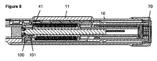
用量が選択されている状態の機構を用いて、ユーザは、機構を起動して用量の送達を始めることができる。用量の送達は、デバイスの近位端でユーザが用量ボタン70を押し下げることによって開始される。図7および8は、用量ボタン70が休止状態にある(図7)、またボタン70が押し下げられている(図8)、2つの位置にあるデバイスを示す。用量ボタン70が押し下げられると、ダイヤルスリーブ60および用量ボタン70に対するスプライン71、72が係合解除されて、用量セレクタ80が送達機構から回転方向で分離されるので、用量セレクタ80は投薬中に回転しない。用量ボタン70はロッキングアーム100に対して作用し、それが軸方向で移動して、ドライバ40に対するスプライン歯係合41、101を分離する。ここで、ドライバ40は回転することができ、用量インジケータ120、ダイヤルスリーブ60、およびクラッチ板130を介してねじりばね90によって駆動される。ドライバ40の回転によって親ねじ30が、それらのスプライン係合によって回転し、次に親ねじ30は、ハウジング10に対するねじ係合によって前進する。また、数字スリーブの回転によってゲージ要素110がそのゼロ位置へと軸方向で横断して戻り、それによってゼロ用量アバットメント122が機構を停止させる。
Using the mechanism with the dose selected, the user can activate the mechanism and begin delivering the dose. Dose delivery is initiated by the user depressing the
送達中の触覚のフィードバックは、ハウジング10に統合された従順なカンチレバービーム13を介して提供され、カンチレバービームは、ドライバ40のスプライン歯41と軸方向でインターフェース接続し、それによってスプライン歯の間隔が、単一単位の投薬に要するドライバ40の回転に相当する。投薬中、ドライバ40が回転するにつれて、スプライン機能41はクリッカアーム13と係合して、各用量単位が送達されると可聴のクリック音を生成する。用量の送達は、ユーザが用量ボタン70を押し下げ続けている間、上述の機械的相互作用を介して継続する。
Tactile feedback during delivery is provided via a
ユーザが用量ボタン70を解放すると、クラッチばね140および戻しばね150は協働して、用量ボタンをその休止位置に戻す。戻しばね150は、ロッキングアーム100を介して用量ボタン70に作用するので、これも軸方向で並進される。ロッキングアーム100がその休止位置に向かって戻るにつれて、スプライン101がドライバ40のスプライン機能41と係合して、ドライバ40をハウジング10に対して回転方向で制約し、用量の送達を中止させる。
When the user releases the
用量の送達中、ドライバ40およびダイヤルスリーブ60はともに回転するので、ナット50内において相対運動は生じない。したがって、ナット50はダイヤル設定の間のみ、ドライバ40上のそのアバットメントに向かって移動する。
During dose delivery, the
一旦用量の送達が停止されると、用量インジケータ120がゼロ用量アバットメントに戻ることによって、ユーザは用量ボタン70を解放してもよく、それによってロッキングアーム100のスプライン歯はドライバ40と再係合される。ここで、機構は休止状態に戻る。
Once dose delivery is stopped, the user may release the
スプライン歯41、101をドライバ40およびロッキングアーム100の一方または両方で角度を付けて、用量ボタン70が解放されたとき、スプライン歯の再係合によってドライバ40がわずかに「巻き戻り」、それによって、ゲージ要素110のゼロ用量停止アバットメント122に対する用量インジケータ120の係合が除去されることが可能である。これにより、デバイスを後に続く用量のためにダイヤルしたときに、それがなければ親ねじ30のわずかな前進および薬剤の投薬に結び付く場合がある、機構の(たとえば、許容差による)遊びの影響が取り除かれる(用量インジケータ120のゼロ用量止め具122が機構をもう制約しなくなり、その代わりに、駆動スリーブとロッキングアーム100との間のスプラインの制約に戻ることによる)。
When the
用量の終了時、追加の可聴および/または触覚のフィードバックが、投薬中に提供されるクリック音とは異なるクリック音の形態で提供されて、デバイスがそのゼロ位置に戻っていることがユーザに通知される。これは、3つの構成要素、すなわち用量インジケータ120、ゲージ要素110、およびロッキングアーム100の相互作用によって達成される。この実施形態により、フィードバックを用量送達の終了時にのみ作成し、デバイスがゼロ位置に戻る方向または離れる方向でダイヤルされた場合には作成しないことが可能になる。図4は、用量がダイヤルされたときの機能の位置を示す。ロッキングアーム100が用量インジケータ120の可撓性アーム123に接触しておらず、したがってダイヤル中、可撓性アーム123は偏向されないことが分かる。しかしながら、用量送達中、ロッキングアーム100は軸方向で前進した(遠位側)位置にあり、それによって数字スリーブの可撓性アーム123が軸方向で偏向される。図4で分かるように、ロッキングアーム100は、ボタン70の押下げの際にロッキングアーム100が遠位方向で変位した場合、アーム123の突出部124と相互作用する、遠位面102を有するカットアウトまたはスロットを有する。したがって、用量ボタン70を押し下げたときにのみ、すなわち、用量設定中または用量キャンセル中ではなく用量投薬中、用量インジケータ120上の可撓性アーム123はロッキングアーム100によって軸方向で偏向される。用量インジケータ120がそのゼロ位置に戻ると、可撓性アーム123は、ゲージ要素110の半可撓性アーム114のさらなる突出部125と接触する。ゼロ位置では、可撓性アーム123は、ゲージ要素110のアーム114を乗り越えて、別個のクリック音フィードバックを作成する。図4の実施形態では、アーム114は、ゼロ位置における可聴および/または触覚のフィードバックを増加させる、突出部125がカチッと留まる陥凹部115を有する。
At the end of the dose, additional audible and / or tactile feedback is provided in the form of a click sound different from the click sound provided during medication to notify the user that the device has returned to its zero position. Is done. This is accomplished by the interaction of three components: a
第2の実施形態が図10〜18に示される。このデバイスの全体的な機能は第1の実施形態に類似している。したがって、同一のまたは非常に類似した構成要素は、第1の実施形態と同じ参照番号を付されている。図10の構成部品の概観から理解することができるように、この実施形態は、トリガインナー210と呼ばれる内部作動要素を用いてドライバ40を変位させるトリガ200を有する。トリガ200は、トリガハウジング220を用いてハウジング10上で枢動可能に保持される。それに加えて、内側ハウジング190およびグリップカバー180が提供される。すべての構成要素は、トリガ200およびトリガハウジング220を除いて、機構の共通の主軸を中心にして同心的に位置する。
A second embodiment is shown in FIGS. The overall function of this device is similar to the first embodiment. Accordingly, identical or very similar components are given the same reference numbers as in the first embodiment. As can be seen from the component overview of FIG. 10, this embodiment has a
ハウジング10は、液体薬物カートリッジ170のための位置、トリガハウジング220の取付け地点、内側ハウジング190を堅く制約するインターフェース、用量インジケータ120の用量数字を見ることができるスロット11、およびその外表面上で用量セレクタ80を軸方向で保持する機能、たとえば周溝を提供する。
The
取外し可能なキャップ(図示せず)は、ハウジング10のカートリッジホルダ20の上に適合するように提供され、機構が使用されていないとき、クリップを介してハウジング10上に保持される。キャップがハウジング10上に適合されたとき、機械的インターロックがトリガ200とともに作成され、それによってトリガ200がその休止位置から押し下げられなくなる。
A removable cap (not shown) is provided to fit over the
親ねじ30は雄ねじ山31を有し、スプライン接続インターフェースを介してドライバ40に対して回転方向で制約される。インターフェースは、少なくとも1つの長手方向溝またはトラック32と、それに対応するドライバ40の突出部またはスプライン44とを含む。第1の実施形態と同様に、回転させると、親ねじ30は、ハウジング10とのねじ込みインターフェースを通して、ドライバ40に対して軸方向で動かされる。
The
ドライバ40は、ダイヤルスリーブ60とのインターフェースから、クラッチ板130を介して、軸方向で当接する際に生じる、内側ハウジング190とのスプライン歯インターフェース41、191まで延びる。これによって、用量設定中のドライバ40に対する回転方向の制約が提供される。第1の実施形態と同様に、ナット50用の端部止め具が提供される(図示せず)。
The
ナット50は、ダイヤルスリーブ60とドライバ40との間に位置する。ナットは、スプライン接続インターフェースを介して、ダイヤルスリーブ60に対して回転方向で制約される。ナットは、ダイヤルスリーブ60とドライバ40との間の相対回転が生じたとき、ねじ込みインターフェースを介して、ドライバ40に対して螺旋状経路に沿って動く。この場合も、ナット50とドライバ40およびダイヤルスリーブ60との係合は逆であってもよい。したがって、ナット50は半割りナットとして示されているが、フルナットの形態を有してもよい。
The
ダイヤルスリーブ60は、軸方向で当接する際に生じる、クラッチ板130上のラチェットインターフェースを介してドライバ40に連結される。歯42、131によって形成されるラチェットは、各用量単位に対応する、ダイヤルスリーブ60とドライバ40との間の戻り止め位置を提供し、時計回転および反時計回転の相対回転中に異なる傾斜した歯の角度で係合する。
The
用量セレクタ80は、ハウジング10に対して軸方向で制約される。スプライン接続インターフェース81、132を介して、クラッチ板130に対して回転方向で制約される。グリップカバー180は、用量セレクタ80に対して堅く制約される。
The
ねじりばね90は、一端で内側ハウジング190に、他端でダイヤルスリーブ60に取り付けられる。ねじりばね90は組立て時に事前巻回され、それによって、ゼロ単位がダイヤルされた位置に機構があるとき、ダイヤルスリーブ60にトルクを加える。用量セレクタ80を回転させて用量を設定する動作は、内側ハウジング190に対してダイヤルスリーブ60を回転させ、ねじりばね90を巻き上げる。
The
ゲージ要素110は、回転を防ぐが、スプライン接続インターフェースを介してハウジング10に対して軸方向で並進運動できるように制約される。また、用量インジケータ120の回転によってゲージ要素110が軸方向で並進運動するように、用量インジケータ120に対してねじ係合されている。ゲージ窓の設計および機能は第1の実施形態と同じである。
用量インジケータ120は、スプライン接続インターフェースを介して、ダイヤルスリーブ60に対して回転方向で制約される。それらは、内側ハウジング190によって、回転できるが並進運動できないように制約される。用量インジケータ120は、ゲージ要素110およびハウジング10のスロット11を通して見える、ダイヤルされた薬剤の用量を示す一連の数字で印を付けられる。
The
クラッチばね140は、クラッチ板130とグリップカバー180との間に位置し、クラッチ板130およびドライバ40を機構のカートリッジ端部に向かわせるように作用する。ラチェット歯61、133(実際には、スプライン機能)は、ダイヤルスリーブ60とクラッチ板130との間で恒久的に係合される。クラッチばね140は、クラッチ板130をカートリッジ端部に向かって付勢して、スプライン132、81を用量セレクタ80の内表面上で係合する。図14は、デバイスの近位端とともにクラッチ板130をより詳細に示す。
支承部160は、親ねじ30に対して軸方向で制約され、液体薬剤カートリッジ170内の栓に対して作用する。
The
内側ハウジング190は、ハウジング10に対して堅く制約される管状要素であり、トリガ200が、歯付きインターフェース41、191によって押し下げられていないとき、ドライバ40をロックする。その遠位端付近に、用量投薬中に駆動スリーブ歯41と相互作用して、可聴および/または触覚のフィードバックを作成する、クリッカアーム192(図15a、b)がある。
トリガ200は、ハウジング10内で枢動するように制約される。トリガ200が押し下げられると、トリガインナー210に作用してトリガインナー210を軸方向で並進運動させ、それによってドライバ40を軸方向で並進させ、ドライバ40を内側ハウジング190に対するそのスプライン歯係合から係合解除する。トリガによるデバイスの作動は、ユーザが投薬力を及ぼさなければならないデバイスと比較して、作動力が低くなる。
The
トリガインナー210のリング状要素は、トリガ200が押し下げられると、軸方向で動くように制約される。トリガインナー210は、近位方向で延びる2つの突出部211を有する(図15a)。突出部211は、トリガ200が押し下げられると、ドライバ40を内側ハウジング190から係合解除するように、ドライバ40に対して作用する(図15b)。
The ring-shaped element of the trigger inner 210 is constrained to move axially when the
トリガハウジング220は、ハウジング10内にクリップ留めされ、トリガ200をそのハウジング10との枢動インターフェース内で保持する。
The
以下、使い捨ての薬物送達デバイスおよびその構成要素の機能について、より詳細に説明する。 Hereinafter, the functions of the disposable drug delivery device and its components will be described in more detail.
ユーザは、用量セレクタ80を時計方向で回転させることによって液体薬剤の可変用量を選択し、それによってダイヤルスリーブ60の、およびしたがって用量インジケータ120の同一の回転が発生する。ダイヤルスリーブの回転によって、ねじりばね90の装荷が引き起こされて、内部に蓄積されたエネルギーが増加する。用量インジケータ120が回転するにつれて、ゲージ要素110はそのねじ係合によって軸方向で並進し、それによってダイヤルされた用量の値が示される。上述のように、ゲージ要素110は窓111のどちらかの側の範囲に、ダイヤルされた/送達された用量値に対する追加のフィードバックを提供する視覚的な違いを有してもよい、フランジ112、113を有する。トリガ機構はまた、ダイヤル中、特に器用さに限界があるユーザを支援する、ダイヤルグリップの特徴的部材であるグリップカバー180上に、人間工学的に先細または扁平な機能181を有する。ドライバ40は、そのスプライン歯41と内側ハウジング190との係合により、回転しないようにされる。したがって、ラチェットインターフェース42、131を介して、クラッチ板130とドライバ40との間で相対回転が生じるはずである。ナット50の動きおよびセット用量のキャンセルは、第1の実施形態に関して説明したのと同じである。
The user selects a variable dose of liquid medication by rotating the
第1の実施形態に関して上述のように用量が設定された後、デバイスは、用量投薬の準備ができている。用量の送達は、デバイスの側面にあるトリガ200をユーザが押し下げることによって開始される。図17および18は、トリガ200が休止状態にある(図17)、またトリガ200が押し下げられている(図18)、2つの位置にあるデバイスを示す。トリガ200が押し下げられると、トリガはトリガインナー210に作用して、それをカートリッジ170から軸方向で離れるように動かす。トリガインナー210は、軸方向で変位させるようにドライバ40に作用し、すなわち、ドライバ40はクラッチ板130を軸方向で動かして、クラッチ板130を用量セレクタ80から係合解除する。次に、駆動スリーブスプライン歯41は、内側ハウジング190の対応する歯191から係合解除される。ここで、ドライバ40は回転することができ、用量インジケータ120、ダイヤルスリーブ60、およびクラッチ板130を介してねじりばね90によって駆動される。ドライバ40の回転によって親ねじ30が、それらのスプライン係合によって回転し、次に親ねじ30は、内側ハウジング190に対するそのねじ係合によって前進する。用量の送達中、ドライバ40およびダイヤルスリーブ60はともに回転するので、ナット50内において相対運動は生じない。したがって、ナット50はダイヤル設定の間のみ、ドライバ40上のそのアバットメントに向かって移動する。
After the dose is set as described above with respect to the first embodiment, the device is ready for dose dosing. Dose delivery is initiated by the user depressing the
用量の送達は、上述の機械的相互作用を介して継続し、ユーザはトリガ200を押し下げ続ける。ユーザがトリガ200を解放した場合、その休止位置に戻り、ドライバ40は内側ハウジング190に対して回転方向で制約されるので、用量の送達が中止される。
Dose delivery continues through the mechanical interaction described above, and the user continues to depress
また、用量インジケータ120の回転によって、ゲージ要素110がそのゼロ位置まで軸方向で横断して戻り、それによってゼロ用量アバットメント122が機構を停止させる。一旦用量の送達が停止されると、用量インジケータ120がゼロ用量アバットメント122に戻ることによって、ユーザはトリガ200を解放してもよく、それによって内側ハウジングのスプライン歯191は駆動スリーブの歯41と再係合される。ここで、機構は休止状態に戻る。
Also, rotation of the
送達中の触覚のフィードバックは、内側ハウジング190に統合されたクリッカアーム192を介して提供されるが、それは、トリガ200が押し下げられ、ドライバ40がその軸方向投薬位置に、すなわちその近位位置にあるとき、ドライバ40のスプライン歯41と径方向でインターフェース接続する。スプライン歯41の間隔は、単一単位の投薬に要するドライバ40の回転に対応する。投薬中、ドライバ40が回転するにつれて、スプライン機能41はクリッカアーム192と係合して、各用量単位が送達されるごとに可聴のクリック音を生成する。
Tactile feedback during delivery is provided via a
スプライン歯41、191をドライバ40および内側ハウジング191の一方または両方で角度を付けて、トリガ200が解放されたとき、スプライン歯41、191の再係合によってドライバ40がわずかに「巻き戻り」、それによって、ゲージ要素110のゼロ用量止め具アバットメント122に対する用量インジケータ120の係合が除去されることが可能である。これにより、デバイスを後に続く用量のためにダイヤルしたときに、それがなければ親ねじ30のわずかな前進および薬剤の投薬に結び付く場合がある、機構の(たとえば、許容差による)遊びの影響が取り除かれる(用量インジケータ120のゼロ用量止め具122が機構をもう制約しなくなり、その代わりに、駆動スリーブと内側ハウジング190との間のスプラインの制約に戻ることによる)。
When the
用量の終了時、追加の触覚のフィードバックが、投薬中に提供される「クリック音」とは異なる「クリック音」の形態で提供されて、3つの構成要素、すなわち用量インジケータ120、ゲージ要素110、およびトリガインナー210の相互作用を介して、デバイスがそのゼロ位置に戻っていることがユーザに通知される。この実施形態により、フィードバックを用量送達の終了時にのみ作成し、デバイスがゼロ位置に戻る方向または離れる方向でダイヤルされた場合には作成しないことが可能になる。図16aは、用量がダイヤルされたときの機能の位置を示す。用量インジケータ120の半可撓性アーム123は、ゲージ要素110の可撓性アーム114に接触せず、したがってダイヤル中、可撓性アーム114は偏向されず、すなわち2つのアームが相互作用することなく半可撓性アーム123の上を通過することが分かる。用量送達中、トリガ200はトリガインナー210を軸方向で押しやるので、用量の終了に向かって、トリガインナー210上のアーム212はゲージ要素110上の可撓性アーム114を軸方向で偏向させ(図16b)、それによって、機構がゼロに戻るにつれて、可撓性アーム114が用量インジケータ120の半可撓性アーム123の突出部125に接触して、機構がゼロ止め具位置に達すると「クリック音」を生成する。アーム114は、その径方向内側に、半可撓性アーム123の突出部125と相互作用する突出部または陥凹部(図示せず)を有してもよい。
At the end of the dose, additional tactile feedback is provided in the form of a “click sound” that is different from the “click sound” provided during medication, so that there are three components: a
第3の代替実施形態が図19および20に示される。第1の実施形態と同様に、この第3の実施形態のデバイスはその近位端に用量ボタン70を有する。デバイスは、用量投薬中にデバイスを起動する、並進する用量インジケータ120を特徴とする。換言すれば、デバイスは、用量ボタン70作動中の用量インジケータ120の軸方向移動を利用して、ドライバ40をハウジング10とのその回転ロックから解放する。これにより、機構の外径および長さが低減される。図19は、休止位置にあるデバイスを示し、図20では、用量ボタン70は押し下げられている。構成要素の機能は主に第1の実施形態に対応する。
A third alternative embodiment is shown in FIGS. Similar to the first embodiment, the device of this third embodiment has a
この第3の実施形態では、用量ボタン70は、用量インジケータ120との軸方向の当接を有する。用量インジケータ120の長さにより、第1の実施形態の別個のダイヤルスリーブは省略される。その遠位領域では、用量インジケータ120は、ハウジング10にスプライン接続され、ドライバ40の対応する歯41と係合する歯を有する、別個のロッキングアーム230に対して作用する。したがって、用量ボタン70が押し下げられたときに用量インジケータ120が軸方向で動くのにつれて、ロッキングアーム230は軸方向で動かされて、ドライバ40から係合解除され、ねじりばね90が用量を送達するのを可能にする。同様に、用量ボタン70が解放されると、用量インジケータ120およびロッキングアーム230は、軸方向ばね240の作用を受けてそれらの元の軸方向位置に戻り、ドライバ40は回転に対抗して再びロックされる。
In this third embodiment, the
ゲージ要素110は用量インジケータ120にねじ止めされるので、用量ボタン70が押し下げられ解放されると、用量インジケータ120とともに軸方向で動き、したがって、ハウジング10のゲージ要素110およびレンズまたはスロット11は常に用量インジケータ120と位置合わせされたままなので、正確な用量が表示される。
Since the
追加のばね240は、用量インジケータ120の遠位端に作用して、休止位置で、すなわち数字スリーブの近位側位置で機構を付勢する。製造上の理由から、ドライバ40は、図19および20に示されるような2つの堅く固定された構成部品を含んでもよい。ナット50は、ドライバ40と(拡張された)用量インジケータ120との間に位置する。
An
用量インジケータ120は用量ボタン70が作動すると軸方向で並進するが、用量設定中も用量投薬中も、用量インジケータ120は軸方向運動しない。
The
3つの実施形態の上記の記載から理解できるように、本発明の顕著な特徴および利点としては次のものが挙げられる。 As can be understood from the above description of the three embodiments, the salient features and advantages of the present invention include the following.
設定および/または残り用量は、デバイス内において軸方向で動く窓を通して表示される−「ゲージ」機能。これは追加の視覚的な用量進行フィードバックを提供する。このフィードバックは、この窓111のどちらかの側、すなわちフランジ112、113が、別個の色および/または印などの機能を有する場合に、向上させることができる。
Settings and / or remaining dose are displayed through an axially moving window in the device-"gauge" function. This provides additional visual dose progression feedback. This feedback can be improved if either side of this
用量インジケータ120は、いずれの実施形態でも螺旋状に並進運動しない。
The
第2の実施形態は、用量設定を支援するグリップカバー180を備えた、大きいユーザフレンドリーな用量セレクタ80のプロファイルを有する。これは、端部にボタンがない場合にのみ実現可能である。
The second embodiment has a large user-
第1および第3の実施形態の終了ボタン機構は、用量設定を援助する大型の用量セレクタ80を有する。
The end button mechanism of the first and third embodiments has a
用量終了クリック音は、用量設定またはキャンセルではなく、用量送達中に動作する、各機構に組み込まれる。 A dose end click is incorporated into each mechanism that operates during dose delivery rather than dose setting or cancellation.
代替の第3の実施形態は、第1の実施形態の終了ボタン機構のために存在し、それによって用量インジケータ120は、用量送達ではなく用量ボタン70の作動および解放中に軸方向で動く。
An alternative third embodiment exists for the end button mechanism of the first embodiment, whereby the
注射デバイス1の代替の第4の実施形態が図21に分解組立図で示される。注射デバイスは、液体薬剤カートリッジを除いて19個の構成要素を含む。より詳細には、デバイスはハウジング410を含み、それは、主ハウジング411と、近位側キャップ412およびカートリッジホルダ413と、ダイヤルグリップ420と、投薬ボタン430と、ダイヤルチューブ440と、最終用量ナット450と、スリーブ状のクリッカ460と、投薬ばね470と、用量インジケータ(ダイヤルスリーブ)480と、摺動ゲージ490と、駆動スリーブ501および駆動チューブ502を含む駆動部材500と、モータばね510と、収納スプール520と、支承部531を備えたピストンロッド(親ねじ)530と、レンズ(図示せず)と、キャップ(図示せず)とを含む。ほとんどの構成要素は、図22に示されるように、機構の2つの主軸IおよびIIのうち1つを中心にして同軸で位置する。
An alternative fourth embodiment of the injection device 1 is shown in exploded view in FIG. The injection device includes 19 components except for the liquid drug cartridge. More particularly, the device includes a
ピストンロッド530はハウジング510内に位置する。駆動部材500は、ピストンロッド530に恒久的に連結され、駆動部材500は、駆動部材500がハウジング410に対して回転方向で制約される用量設定位置と、駆動部材500がハウジング410から回転方向で脱結合される用量投薬位置との間で、軸方向で可動である。駆動部材500を駆動する動力リザーバ510は、駆動部材500に対して軸方向および回転方向で制約された、第1のスプール520に取り付けられた第1の端部および第2のスプールに取り付けられた第2の端部を有する、動力リザーバとしての、逆方向に巻かれた板状の渦巻ばねを含む。たとえば、第2のスプールは駆動スリーブ501の一体部材である。図面に示される実施形態では、ばね510の第2の端部は、幅が低減された部分と、幅が低減された部分と比べて増加した幅を有する自由端部分とを含み、駆動部材500は、より詳細には駆動スリーブ501は、軸方向スロット503および隣接した幅の狭い陥凹部を有する円筒状のスプール部分を含む。
好ましくは、用量インジケータ480は、ハウジング410に対して軸方向で制約され、用量設定中には、第1の方向(用量を増加させる)または第2の反対方向(用量を減少させる)のどちらかで、ハウジングに対して回転し、用量投薬中には、第2の反対方向でハウジングに対して回転する。ゲージ要素490は、ハウジング410と用量インジケータ480との間に少なくとも部分的に介在し、ハウジング410の少なくとも1つのアパーチャまたは窓を通して少なくとも部分的に見える。さらに、ゲージ要素490は、ハウジング410内において軸方向でガイドされ、用量インジケータ480とねじ係合されており、それによって、用量インジケータ480が回転するとゲージ要素490が軸方向で変位する。ハウジング410はアパーチャまたは窓を有し、ゲージ要素490は、用量インジケータ480の少なくとも一部がアパーチャまたは窓を通して見えるように、ハウジングのアパーチャまたは窓に対して位置する、さらなるアパーチャまたは窓を有する。
Preferably, the
特に、アパーチャは、用量の投薬中にユーザに見える位置で、主ハウジング411上に位置してもよい。これはデバイスの遠位端に近くてもよい。特に、これは、用量インジケータ480の番号表示を実現可能に位置させることができない位置であってもよい。複数のゲージアパーチャも存在してもよい。特に、デバイスの両側に位置する2つのゲージアパーチャが存在してもよい。これにより、左利きの動作を好むユーザにとって、または代替のグリップでデバイスを保持することを好むユーザにとって、アナログゲージ機能の視認性が向上する。アナログゲージは、用量の投薬中におけるデバイスの用量位置のインジケータとして特に有益である。用量の投薬中、数字の桁の表示が、個々の用量位置の印に対して速く変化しすぎて判読できないことがある。したがって、用量が投薬される速度、およびこれから投薬される薬剤の量をユーザが理解することが困難なことがある。用量が投薬されるにしたがってさらに表面を被覆していく、アナログゲージの軸方向運動によって、投薬イベント中の投薬速度およびこれから投薬される薬剤の量の、単純な目に見えるインジケータが得られる。
In particular, the aperture may be located on the
注射デバイスは、最大設定可能用量および最小設定可能用量を規定するリミッタ機構を含む。リミッタ機構は、最小用量(ゼロ)位置で当接する、用量インジケータ480上の第1の回転止め具およびゲージ要素490上の第1のカウンタ止め具と、最大用量位置で当接する、用量インジケータ480上の第2の回転止め具およびゲージ要素490上の第2のカウンタ止め具とを含んでもよい。
The injection device includes a limiter mechanism that defines a maximum settable dose and a minimum settable dose. The limiter mechanism is on a
投薬ボタン430は、軸方向で変位可能であり、ハウジング410に対して軸方向で制約されたダイヤルグリップ420によって取り囲まれて位置する。クリッカスリーブ460は、ハウジング410に対して回転方向で制約され、近位側の用量設定位置と遠位側の用量投薬位置との間で、ハウジングに対して軸方向で変位可能である。さらに、クリッカスリーブ460は、用量設定中には回転可能である、ダイヤルスリーブ440の対応する歯を解放可能に係合する歯を含む。用量インジケータ480は、クリッカスリーブ460によって第1の方向で変位可能であり、用量投薬中のみ、デバイスがその最小用量(ゼロ)位置に達すると、ゲージ要素490の突出したセクションによって第2の反対方向で変位可能である、可撓性のクリッカアームを含んでもよい。
The
注射デバイスは、カートリッジに残っている液体の量を超える用量の設定を防ぐための最終用量保護機構をさらに含んでもよい。この最終用量保護機構は、クリッカスリーブ460とダイヤルスリーブ440との間に介在して位置するナット部材450を含む。
The injection device may further include a final dose protection mechanism to prevent setting a dose that exceeds the amount of liquid remaining in the cartridge. This final dose protection mechanism includes a
注射デバイスでは、第1のスプール520は、第1の長手方向軸I上でピストンロッド530と同心で位置し、第2のスプール、すなわち駆動スリーブ501は、第2の長手方向軸II上に位置し、第1の長手方向軸Iは、第2の長手方向軸IIと平行であり、そこから離隔される。上述のように、駆動部材500は、第1の長手方向軸Iを中心にして回転可能な駆動チューブ502と、第2の長手方向軸IIを中心にして回転可能な駆動スリーブ501とを含んでもよい。駆動スリーブ501は、駆動スリーブ501がハウジング410に対して回転方向で制約される用量設定位置と、駆動スリーブ501がハウジング410から回転方向で脱結合される用量投薬位置との間で、軸方向で可動である。駆動チューブ502は、駆動スリーブ501に対して、または少なくとも駆動スリーブ501がその用量投薬位置にあるとき、恒久的に回転方向で連結される。
In the injection device, the
クラッチ483、505は、用量インジケータ480と駆動部材500との間で介在して提供され、クラッチ483、505は、用量設定中の用量インジケータ480と駆動部材500との間の相対的な回転運動を可能にし、用量投薬中の用量インジケータ480と駆動部材500との間の相対的な回転運動を防ぐ。図21に示されるように、クラッチは、駆動スリーブ501の遠位側にある歯505のリングと、用量インジケータ上の内スプライン483とを含む。駆動スリーブ501はその近位端に、駆動チューブ502上の対応する歯と噛み合う歯506のリングをさらに有する。それに加えて、歯506は、駆動スリーブ501の(近位側)用量設定位置において、ハウジングに対して回転方向で駆動スリーブ501を連結する。
上述の特徴はそれぞれ、他の特徴とは独立しており、また、クラッチ、ラチェット、クリッカ、用量ディスプレイ、または作動手段など、他の構成部品の内部の機能とは独立している。 Each of the features described above is independent of other features and independent of internal functions of other components such as clutches, ratchets, clickers, dose displays, or actuation means.
すべての実施形態のさらなる一般的な特徴は、デバイスがダイヤル延長を有していない点、すなわち、用量がダイヤルされていてもいなくてもデバイスの長さが同じである点である。それに加えて、用量セレクタ80は投薬の間旋回せず、ダイヤル設定をより簡単にするように形作られる(平面状または大きい直径)。ゲージ要素110は、用量の進行中にユーザに対して定性的フィードバックを提供する。これは、数字スリーブ上の個々の数字または記号を識別するのが困難であると感じることがある、視覚障害のあるユーザにとって特に重要である。それらはすべて、ユーザに対して著しい人間工学上の利益を提供すべきである。
A further general feature of all embodiments is that the device does not have a dial extension, i.e. the length of the device is the same whether or not the dose is dialed. In addition, the
Claims (14)
ハウジング(10;410)と、
該ハウジング(10、410)内に位置する用量インジケータ(120;480)に動作可能に接続された用量設定部材(80、60;420、440)であって、該用量設定部材(80、60;420、440)および用量インジケータ(120;480)は協働して注射デバイスから排出される用量を設定し、用量インジケータ(120;480)は、用量設定中、ハウジング(10;410)内でハウジング(10;410)に対して、好ましくは360°を超える回転運動のみを受けるように適用される、該用量設定部材と、
用量を注射デバイスから排出するのに必要な力を提供するように適用された弾性部材(90;510)を含み、
注射デバイスは、駆動部材(40、500)がハウジング(10、410)に対し回転方向で制約される用量設定位置と、駆動部材(40、500)がハウジングから回転方向に脱結合される用量投薬位置との間で軸方向に移動可能である駆動部材(40、500)と、
ハウジング(10;410)に対して回転方向で制約され、ハウジング(10;410)に対して軸方向で変位可能であるゲージ要素(110;490)
をさらに含むことを特徴とする前記注射デバイス。 An injection device,
A housing (10; 410);
A dose setting member (80, 60; 420, 440) operatively connected to a dose indicator (120; 480) located within the housing (10, 410), the dose setting member (80, 60; 420, 440) and the dose indicator (120; 480) cooperate to set the dose to be ejected from the injection device, and the dose indicator (120; 480) is the housing within the housing (10; 410) during dose setting. (10; 410) with respect to applied preferably to receive only the rotary movement of more than 360 °, and the dose setting member,
It includes; (510 90), applied elastic member to provide the force necessary to discharge the dose from the injection device
The injection device comprises a dose setting position in which the drive member (40, 500) is rotationally constrained relative to the housing (10, 410), and a dose dispenser in which the drive member (40, 500) is decoupled from the housing in the rotational direction. A drive member (40, 500) movable axially between positions;
Gauge element (110; 490) constrained in the rotational direction relative to the housing (10; 410) and displaceable in the axial direction relative to the housing (10; 410)
The injection device further comprising:
該ピストンロッド(30;530)の駆動トラック(32)の少なくとも一部と係合し、用量インジケータ(120;480)に解放可能に結合された駆動部材(40;500)であって、注射デバイスから用量を排出する間、ピストンロッド(30;530)を駆動しともに回転するように適用された駆動部材(40;500)とを含み、
ここで、ハウジング(10;410)は、ピストンロッド(30;530)の回転によってピストンロッド(30;530)の軸方向運動がもたらされるように、ピストンロッド(30;530)のねじ付き外表面(31)と協働するねじ付き部分(12)を有する
、請求項1に記載の注射デバイス。 A piston rod (30; 530) having a threaded outer surface with at least one drive track (32) arranged longitudinally of the outer surface of the piston rod (30; 530);
A drive member (40; 500) that engages at least a portion of a drive track (32) of the piston rod (30; 530) and is releasably coupled to a dose indicator (120; 480), the injection device A drive member (40; 500) adapted to drive and rotate with the piston rod (30; 530) while discharging a dose from
Here, the housing (10; 410) is a threaded outer surface of the piston rod (30; 530) such that rotation of the piston rod (30; 530) results in axial movement of the piston rod (30; 530). The injection device according to claim 1, having a threaded portion (12) cooperating with (31).
Applications Claiming Priority (3)
| Application Number | Priority Date | Filing Date | Title |
|---|---|---|---|
| EP13163087 | 2013-04-10 | ||
| EP13163087.3 | 2013-04-10 | ||
| PCT/EP2014/056989 WO2014166908A1 (en) | 2013-04-10 | 2014-04-08 | Injection device |
Publications (2)
| Publication Number | Publication Date |
|---|---|
| JP2016514596A JP2016514596A (en) | 2016-05-23 |
| JP6359635B2 true JP6359635B2 (en) | 2018-07-18 |
Family
ID=48083015
Family Applications (1)
| Application Number | Title | Priority Date | Filing Date |
|---|---|---|---|
| JP2016506892A Active JP6359635B2 (en) | 2013-04-10 | 2014-04-08 | Injection device |
Country Status (15)
| Country | Link |
|---|---|
| US (1) | US10238808B2 (en) |
| EP (1) | EP2983755B1 (en) |
| JP (1) | JP6359635B2 (en) |
| KR (1) | KR20150142010A (en) |
| CN (1) | CN105102032B (en) |
| AR (1) | AR095813A1 (en) |
| AU (1) | AU2014253277A1 (en) |
| BR (1) | BR112015024952A2 (en) |
| DK (1) | DK2983755T3 (en) |
| HK (1) | HK1215201A1 (en) |
| IL (1) | IL240955A0 (en) |
| MX (1) | MX2015014291A (en) |
| RU (1) | RU2015146766A (en) |
| TW (1) | TW201509470A (en) |
| WO (1) | WO2014166908A1 (en) |
Families Citing this family (20)
| Publication number | Priority date | Publication date | Assignee | Title |
|---|---|---|---|---|
| WO2015074977A2 (en) * | 2013-11-22 | 2015-05-28 | Sanofi-Aventis Deutschland Gmbh | Drug delivery device with end of dose feedback |
| US10589032B2 (en) * | 2014-05-26 | 2020-03-17 | Sanofi | Display arrangement for an injection device |
| AR102193A1 (en) | 2014-10-09 | 2017-02-08 | Sanofi Sa | DRIVING HOSE, DRUG ADMINISTRATION DEVICE AND METHOD FOR ASSEMBLY OF A DRUG ADMINISTRATION DEVICE |
| AR102191A1 (en) | 2014-10-09 | 2017-02-08 | Sanofi Sa | METHOD FOR ASSEMBLING A DRIVING SPRING AND DRUG ADMINISTRATION DEVICE WITH A SPRING |
| AR102195A1 (en) | 2014-10-09 | 2017-02-08 | Sanofi Sa | ACCOMMODATION AND DEVICE FOR ADMINISTRATION OF DRUGS WITH THE SAME |
| EP3223887B1 (en) * | 2014-11-24 | 2019-10-09 | Sanofi | Display and drug delivery device herewith |
| PL227678B1 (en) | 2015-12-22 | 2018-01-31 | Copernicus Spolka Z Ograniczona Odpowiedzialnoscia | Control and drive system for the device intended for injection and the device for making injections equipped with such a system |
| EP3397323B1 (en) * | 2015-12-30 | 2020-08-19 | SHL Medical AG | Medicament delivery device |
| US11202866B2 (en) | 2016-07-01 | 2021-12-21 | Sanofi | Drug delivery device |
| EP3108914B1 (en) | 2016-07-07 | 2019-02-27 | Copernicus SP. Z O.O. | Injection device for delivering a defined number of equal doses of a liquid substance |
| US11400230B2 (en) * | 2016-09-09 | 2022-08-02 | Sanofi-Aventis Deutschland Gmbh | Reading device, drug delivery device and drug delivery device in combination with a reading device |
| GB201615453D0 (en) | 2016-09-12 | 2016-10-26 | Norton Healthcare Ltd | Dose display mechanism |
| GB201615450D0 (en) | 2016-09-12 | 2016-10-26 | Norton Healthcare Ltd | Dose display mechanism |
| GB201615433D0 (en) | 2016-09-12 | 2016-10-26 | Norton Healthcare Ltd | Dose setting and display mechanism |
| CN110062641B (en) * | 2016-12-08 | 2021-12-21 | 赛诺菲-安万特德国有限公司 | Injection device |
| PL232651B1 (en) | 2017-07-18 | 2019-07-31 | Copernicus Spolka Z Ograniczona Odpowiedzialnoscia | Coupling with locking system for the medical injecting device |
| CN111295214A (en) * | 2017-11-07 | 2020-06-16 | 赛诺菲-安万特德国有限公司 | Injection device with pre-selector |
| WO2019091879A1 (en) * | 2017-11-07 | 2019-05-16 | Sanofi-Aventis Deutschland Gmbh | Injection device |
| USD862690S1 (en) * | 2018-07-03 | 2019-10-08 | Haselmeier Ag | Medical injector |
| WO2023041548A1 (en) | 2021-09-16 | 2023-03-23 | Sanofi | Dose setting and drive mechanism for a drug delivery device |
Family Cites Families (19)
| Publication number | Priority date | Publication date | Assignee | Title |
|---|---|---|---|---|
| DE29703820U1 (en) * | 1997-03-03 | 1998-07-02 | Medico Dev Investment Co | Injection device |
| EP2210634A1 (en) * | 2009-01-22 | 2010-07-28 | Sanofi-Aventis Deutschland GmbH | Drug delivery device dose setting mechanism |
| GB0304823D0 (en) * | 2003-03-03 | 2003-04-09 | Dca Internat Ltd | Improvements in and relating to a pen-type injector |
| GB0304822D0 (en) | 2003-03-03 | 2003-04-09 | Dca Internat Ltd | Improvements in and relating to a pen-type injector |
| CN101084028B (en) * | 2004-10-21 | 2010-06-09 | 诺和诺德公司 | Injection device with torsion spring and rotatable display |
| ATE445429T1 (en) * | 2004-10-21 | 2009-10-15 | Novo Nordisk As | INJECTION DEVICE WITH INTERNAL DOSE INDICATOR |
| CN102895718B (en) | 2006-09-29 | 2015-01-14 | 诺沃—诺迪斯克有限公司 | An injection device with electronic detecting means |
| DE102007026083A1 (en) | 2007-05-25 | 2008-11-27 | Haselmeier S.A.R.L. | injection device |
| DE102007026560A1 (en) | 2007-06-08 | 2009-01-15 | Tecpharma Licensing Ag | Delivery device with axially movable indicator |
| WO2009100550A1 (en) * | 2008-02-11 | 2009-08-20 | Tecpharma Licensing Ag | Administering apparatus comprising a blockable actuation element |
| DE202008011175U1 (en) * | 2008-08-18 | 2010-01-07 | Haselmeier Gmbh | injection device |
| GB0904059D0 (en) | 2009-03-10 | 2009-04-22 | Euro Celtique Sa | Counter |
| GB0918145D0 (en) * | 2009-10-16 | 2009-12-02 | Owen Mumford Ltd | Injector apparatus |
| EP2501421B1 (en) * | 2009-11-20 | 2019-08-21 | Becton Dickinson and Company | Injection device without a gearing |
| PL2555820T3 (en) * | 2010-07-02 | 2015-08-31 | Carebay Holding Ltd Company No 681498 | Preservative-free follicle stimulating hormone solution delivery device |
| JP5894169B2 (en) * | 2010-10-13 | 2016-03-23 | サノフィ−アベンティス・ドイチュラント・ゲゼルシャフト・ミット・ベシュレンクテル・ハフツング | Dose setting mechanism and method of using the same |
| BR112013008912A2 (en) | 2010-10-13 | 2017-07-11 | Sanofi Aventis Deutschland | dose adjustment mechanism and dose adjustment method |
| CN104271185B (en) * | 2012-01-27 | 2017-09-12 | 诺和诺德股份有限公司 | Injection device with slip scale |
| RU2648866C2 (en) * | 2012-08-31 | 2018-03-28 | Санофи-Авентис Дойчланд Гмбх | Drug delivery device |
-
2014
- 2014-04-08 TW TW103112780A patent/TW201509470A/en unknown
- 2014-04-08 DK DK14715909.9T patent/DK2983755T3/en active
- 2014-04-08 US US14/783,507 patent/US10238808B2/en active Active
- 2014-04-08 EP EP14715909.9A patent/EP2983755B1/en active Active
- 2014-04-08 AU AU2014253277A patent/AU2014253277A1/en not_active Abandoned
- 2014-04-08 CN CN201480019972.3A patent/CN105102032B/en active Active
- 2014-04-08 RU RU2015146766A patent/RU2015146766A/en not_active Application Discontinuation
- 2014-04-08 WO PCT/EP2014/056989 patent/WO2014166908A1/en active Application Filing
- 2014-04-08 MX MX2015014291A patent/MX2015014291A/en unknown
- 2014-04-08 JP JP2016506892A patent/JP6359635B2/en active Active
- 2014-04-08 BR BR112015024952A patent/BR112015024952A2/en not_active IP Right Cessation
- 2014-04-08 AR ARP140101528A patent/AR095813A1/en unknown
- 2014-04-08 KR KR1020157032029A patent/KR20150142010A/en not_active Application Discontinuation
-
2015
- 2015-08-31 IL IL240955A patent/IL240955A0/en unknown
-
2016
- 2016-03-17 HK HK16103138.9A patent/HK1215201A1/en unknown
Also Published As
| Publication number | Publication date |
|---|---|
| CN105102032B (en) | 2020-03-13 |
| US10238808B2 (en) | 2019-03-26 |
| AU2014253277A1 (en) | 2015-10-29 |
| RU2015146766A3 (en) | 2018-03-07 |
| AR095813A1 (en) | 2015-11-11 |
| RU2015146766A (en) | 2017-05-16 |
| HK1215201A1 (en) | 2016-08-19 |
| KR20150142010A (en) | 2015-12-21 |
| WO2014166908A1 (en) | 2014-10-16 |
| BR112015024952A2 (en) | 2017-07-18 |
| TW201509470A (en) | 2015-03-16 |
| IL240955A0 (en) | 2015-11-30 |
| MX2015014291A (en) | 2016-01-20 |
| US20160051770A1 (en) | 2016-02-25 |
| EP2983755B1 (en) | 2020-02-12 |
| EP2983755A1 (en) | 2016-02-17 |
| DK2983755T3 (en) | 2020-05-04 |
| CN105102032A (en) | 2015-11-25 |
| JP2016514596A (en) | 2016-05-23 |
Similar Documents
| Publication | Publication Date | Title |
|---|---|---|
| JP6359635B2 (en) | Injection device | |
| JP6404323B2 (en) | Injection device | |
| JP2019166351A (en) | Injection device | |
| JP6580681B2 (en) | Drug delivery device | |
| JP6419159B2 (en) | Injection device | |
| JP6616410B2 (en) | Spring arrangement and drug delivery device having spring arrangement | |
| JP6695333B2 (en) | Drug injection device with resettable mechanism that allows piston rod to retract when changing drug cartridge | |
| JP6395809B2 (en) | Injection device | |
| JP6395808B2 (en) | Injection device | |
| JP6618994B2 (en) | Resettable drug delivery device | |
| JP6445526B2 (en) | Injection device | |
| JP6629309B2 (en) | Housing and drug delivery device including the same | |
| JP6717813B2 (en) | Automatic drug injection device with torsion drive spring and rotary dose setting and correction mechanism | |
| JP2017530798A (en) | Housing and drug delivery device having housing | |
| JP6515085B2 (en) | Injection device | |
| JP2017534362A (en) | Drive sleeve, drug delivery device, and method of assembling a drug delivery device | |
| JP2017535359A (en) | Drug delivery device having dose setting mechanism and ratchet mechanism | |
| JP2017534364A (en) | Housing, drug delivery device having housing, and method of manufacturing housing | |
| JP6722180B2 (en) | Drug delivery device | |
| JP6618995B2 (en) | Resettable drug delivery device | |
| JP6573666B2 (en) | Drug injection device with resettable mechanism that allows the piston rod to be retracted when changing the drug cartridge | |
| JP6717822B2 (en) | Display and drug delivery device having a display | |
| JP6636019B2 (en) | Insert and drug delivery device with insert | |
| JP6480924B2 (en) | Drug delivery device | |
| JP6637974B2 (en) | Dose dosing assembly for drug delivery device with different leads and multiple thread sections |
Legal Events
| Date | Code | Title | Description |
|---|---|---|---|
| A621 | Written request for application examination |
Free format text: JAPANESE INTERMEDIATE CODE: A621 Effective date: 20170331 |
|
| A131 | Notification of reasons for refusal |
Free format text: JAPANESE INTERMEDIATE CODE: A131 Effective date: 20180206 |
|
| A977 | Report on retrieval |
Free format text: JAPANESE INTERMEDIATE CODE: A971007 Effective date: 20180202 |
|
| A521 | Request for written amendment filed |
Free format text: JAPANESE INTERMEDIATE CODE: A523 Effective date: 20180507 |
|
| TRDD | Decision of grant or rejection written | ||
| A01 | Written decision to grant a patent or to grant a registration (utility model) |
Free format text: JAPANESE INTERMEDIATE CODE: A01 Effective date: 20180529 |
|
| A61 | First payment of annual fees (during grant procedure) |
Free format text: JAPANESE INTERMEDIATE CODE: A61 Effective date: 20180620 |
|
| R150 | Certificate of patent or registration of utility model |
Ref document number: 6359635 Country of ref document: JP Free format text: JAPANESE INTERMEDIATE CODE: R150 |
|
| R250 | Receipt of annual fees |
Free format text: JAPANESE INTERMEDIATE CODE: R250 |
|
| R250 | Receipt of annual fees |
Free format text: JAPANESE INTERMEDIATE CODE: R250 |
|
| R250 | Receipt of annual fees |
Free format text: JAPANESE INTERMEDIATE CODE: R250 |