JP6480924B2 - Drug delivery device - Google Patents
Drug delivery device Download PDFInfo
- Publication number
- JP6480924B2 JP6480924B2 JP2016526631A JP2016526631A JP6480924B2 JP 6480924 B2 JP6480924 B2 JP 6480924B2 JP 2016526631 A JP2016526631 A JP 2016526631A JP 2016526631 A JP2016526631 A JP 2016526631A JP 6480924 B2 JP6480924 B2 JP 6480924B2
- Authority
- JP
- Japan
- Prior art keywords
- dose
- nut
- drug delivery
- delivery device
- final dose
- Prior art date
- Legal status (The legal status is an assumption and is not a legal conclusion. Google has not performed a legal analysis and makes no representation as to the accuracy of the status listed.)
- Expired - Fee Related
Links
Images


Classifications
-
- A—HUMAN NECESSITIES
- A61—MEDICAL OR VETERINARY SCIENCE; HYGIENE
- A61M—DEVICES FOR INTRODUCING MEDIA INTO, OR ONTO, THE BODY; DEVICES FOR TRANSDUCING BODY MEDIA OR FOR TAKING MEDIA FROM THE BODY; DEVICES FOR PRODUCING OR ENDING SLEEP OR STUPOR
- A61M5/00—Devices for bringing media into the body in a subcutaneous, intra-vascular or intramuscular way; Accessories therefor, e.g. filling or cleaning devices, arm-rests
- A61M5/178—Syringes
- A61M5/31—Details
- A61M5/315—Pistons; Piston-rods; Guiding, blocking or restricting the movement of the rod or piston; Appliances on the rod for facilitating dosing ; Dosing mechanisms
- A61M5/31533—Dosing mechanisms, i.e. setting a dose
- A61M5/31535—Means improving security or handling thereof, e.g. blocking means, means preventing insufficient dosing, means allowing correction of overset dose
- A61M5/31541—Means preventing setting of a dose beyond the amount remaining in the cartridge
-
- A—HUMAN NECESSITIES
- A61—MEDICAL OR VETERINARY SCIENCE; HYGIENE
- A61M—DEVICES FOR INTRODUCING MEDIA INTO, OR ONTO, THE BODY; DEVICES FOR TRANSDUCING BODY MEDIA OR FOR TAKING MEDIA FROM THE BODY; DEVICES FOR PRODUCING OR ENDING SLEEP OR STUPOR
- A61M5/00—Devices for bringing media into the body in a subcutaneous, intra-vascular or intramuscular way; Accessories therefor, e.g. filling or cleaning devices, arm-rests
- A61M5/178—Syringes
- A61M5/31—Details
- A61M5/315—Pistons; Piston-rods; Guiding, blocking or restricting the movement of the rod or piston; Appliances on the rod for facilitating dosing ; Dosing mechanisms
- A61M5/31525—Dosing
- A61M5/31528—Dosing by means of rotational movements, e.g. screw-thread mechanisms
-
- A—HUMAN NECESSITIES
- A61—MEDICAL OR VETERINARY SCIENCE; HYGIENE
- A61M—DEVICES FOR INTRODUCING MEDIA INTO, OR ONTO, THE BODY; DEVICES FOR TRANSDUCING BODY MEDIA OR FOR TAKING MEDIA FROM THE BODY; DEVICES FOR PRODUCING OR ENDING SLEEP OR STUPOR
- A61M5/00—Devices for bringing media into the body in a subcutaneous, intra-vascular or intramuscular way; Accessories therefor, e.g. filling or cleaning devices, arm-rests
- A61M5/178—Syringes
- A61M5/31—Details
- A61M5/315—Pistons; Piston-rods; Guiding, blocking or restricting the movement of the rod or piston; Appliances on the rod for facilitating dosing ; Dosing mechanisms
- A61M5/31533—Dosing mechanisms, i.e. setting a dose
- A61M5/31545—Setting modes for dosing
- A61M5/31548—Mechanically operated dose setting member
- A61M5/3155—Mechanically operated dose setting member by rotational movement of dose setting member, e.g. during setting or filling of a syringe
- A61M5/31551—Mechanically operated dose setting member by rotational movement of dose setting member, e.g. during setting or filling of a syringe including axial movement of dose setting member
-
- A—HUMAN NECESSITIES
- A61—MEDICAL OR VETERINARY SCIENCE; HYGIENE
- A61M—DEVICES FOR INTRODUCING MEDIA INTO, OR ONTO, THE BODY; DEVICES FOR TRANSDUCING BODY MEDIA OR FOR TAKING MEDIA FROM THE BODY; DEVICES FOR PRODUCING OR ENDING SLEEP OR STUPOR
- A61M5/00—Devices for bringing media into the body in a subcutaneous, intra-vascular or intramuscular way; Accessories therefor, e.g. filling or cleaning devices, arm-rests
- A61M5/178—Syringes
- A61M5/31—Details
- A61M5/315—Pistons; Piston-rods; Guiding, blocking or restricting the movement of the rod or piston; Appliances on the rod for facilitating dosing ; Dosing mechanisms
- A61M5/31565—Administration mechanisms, i.e. constructional features, modes of administering a dose
- A61M5/3159—Dose expelling manners
- A61M5/31593—Multi-dose, i.e. individually set dose repeatedly administered from the same medicament reservoir
-
- A—HUMAN NECESSITIES
- A61—MEDICAL OR VETERINARY SCIENCE; HYGIENE
- A61M—DEVICES FOR INTRODUCING MEDIA INTO, OR ONTO, THE BODY; DEVICES FOR TRANSDUCING BODY MEDIA OR FOR TAKING MEDIA FROM THE BODY; DEVICES FOR PRODUCING OR ENDING SLEEP OR STUPOR
- A61M5/00—Devices for bringing media into the body in a subcutaneous, intra-vascular or intramuscular way; Accessories therefor, e.g. filling or cleaning devices, arm-rests
- A61M5/178—Syringes
- A61M5/20—Automatic syringes, e.g. with automatically actuated piston rod, with automatic needle injection, filling automatically
Description
本発明は一般に、薬剤のいくつかの使用者可変用量を選択し投薬するための薬物送達デバイスを対象とする。より詳細には、本発明は、薬物送達デバイスのカートリッジ内に残っている液体の量を超える用量を設定しないようにするための用量リミッタを有する薬物送達デバイスに言及する。 The present invention is generally directed to a drug delivery device for selecting and dispensing several user variable doses of a medicament. More particularly, the present invention refers to a drug delivery device having a dose limiter to avoid setting a dose that exceeds the amount of liquid remaining in the cartridge of the drug delivery device.
ペン型薬物送達デバイスには、正式な医療訓練を受けていない人によって定期的な注射が行われる適用例がある。こうした適用例は、糖尿病の患者の間でますます一般的になっており、自己療法により、このような患者は自分の糖尿病の効果的な管理を行うことが可能になる。実際に、このような薬物送達デバイスは、使用者が薬剤のいくつかの使用者可変用量を個別に選択し投薬することを可能にする。本発明は、単に所定の用量を投薬できるようにするだけで設定用量を増加または減少させる可能性のない、いわゆる固定用量デバイスは対象としない。 Pen-type drug delivery devices have applications where regular injections are performed by persons who do not have formal medical training. Such applications are becoming increasingly common among diabetic patients, and self-therapy allows such patients to effectively manage their own diabetes. Indeed, such a drug delivery device allows the user to individually select and dispense several user variable doses of medication. The present invention does not cover so-called fixed-dose devices that simply allow a given dose to be dispensed and do not increase or decrease the set dose.
基本的に2つのタイプの薬物送達デバイス、すなわち:再設定可能デバイス(すなわち、再使用可能なもの)および非再設定可能デバイス(すなわち、使い捨てのもの)がある。たとえば、使い捨てペン送達デバイスは独立型デバイスとして供給される。このような独立型デバイスには、着脱可能な充填済みカートリッジがない。というより、その充填済みカートリッジは、デバイス自体を壊さなければこれらのデバイスから取り出し、取り替えることができない。それゆえに、このような使い捨てデバイスは、再設定可能用量設定機構を有する必要がない。本発明は、両方のタイプのデバイス、すなわち使い捨てデバイスならびに再使用可能デバイスに適用することができる。 There are basically two types of drug delivery devices: a resettable device (ie, reusable) and a non-resettable device (ie, disposable). For example, disposable pen delivery devices are supplied as stand-alone devices. Such stand-alone devices do not have a detachable filled cartridge. Rather, the filled cartridge cannot be removed from these devices and replaced without destroying the devices themselves. Therefore, such a disposable device need not have a resettable dose setting mechanism. The present invention can be applied to both types of devices, namely disposable devices as well as reusable devices.
薬物送達デバイスタイプの別の区分は駆動機構に関連する。たとえば使用者が注射ボタンに力を加えることによって手で駆動されるデバイス、ばねなどによって駆動されるデバイス、およびこれら2つの概念を合わせたデバイス、すなわち使用者が注射力を及ぼすことがやはり必要とされるばね補助式デバイスがある。ばね型デバイスは、あらかじめ負荷がかけられているばねと、用量選択時に使用者によって負荷がかけられるばねとを含む。本発明は、これらすべてのタイプのデバイスに、すなわち駆動ばねがあるデバイスにもないデバイスにも適用することができる。 Another segment of drug delivery device type relates to the drive mechanism. For example, devices that are manually driven by the user applying force to the injection button, devices driven by springs, etc., and devices that combine these two concepts, i.e., the user still needs to exert injection force There are spring assisted devices that are made. Spring-type devices include pre-loaded springs and springs that are loaded by the user during dose selection. The present invention can be applied to all these types of devices, i.e. devices with or without drive springs.
こうしたタイプのペン送達デバイスは(拡大された万年筆に似ていることが多いのでこのように名づけられた)、一般に3つの主な要素、すなわち:多くの場合ハウジングまたはホルダの中に収容されるカートリッジを含むカートリッジ部と;カートリッジ部の一端に連結されたニードルアセンブリと;カートリッジ部の他端に連結された投薬部とから構成される。カートリッジ(アンプルと呼ばれることが多い)は通常、薬剤(たとえば、インスリン)が充填されている貯蔵器と、カートリッジ貯蔵器の一端にある可動ゴム型の栓またはストッパと、多くはくびれている他端にある穿孔可能なゴム封止を有する上部とを含む。圧着環状金属バンドが通常、ゴム封止を適所に保持するために使用される。カートリッジハウジングは通常、プラスチックで作られるが、カートリッジ貯蔵器は従来ガラスで作られてきた。 These types of pen delivery devices (named so often because they resemble enlarged fountain pens) generally have three main elements: a cartridge that is often housed in a housing or holder A needle assembly connected to one end of the cartridge part; and a dosing part connected to the other end of the cartridge part. Cartridges (often referred to as ampoules) are usually a reservoir filled with medication (eg, insulin), a movable rubber stopper or stopper at one end of the cartridge reservoir, and the other end, often constricted And a top having a pierceable rubber seal. A crimped annular metal band is typically used to hold the rubber seal in place. Cartridge housings are usually made of plastic, whereas cartridge reservoirs have traditionally been made of glass.
ニードルアセンブリは通常、交換可能な両頭針アセンブリである。注射の前に、交換可能な両頭針アセンブリがカートリッジアセンブリの一端に取り付けられ、用量が設定されてから、設定用量が投与される。このような着脱可能なニードルアセンブリは、カートリッジアセンブリの穿孔可能な封止端に装着または押し付けられる(すなわち、カチッと留められる)。 The needle assembly is typically a replaceable double-ended needle assembly. Prior to injection, a replaceable double-ended needle assembly is attached to one end of the cartridge assembly and the dose is set before the set dose is administered. Such a removable needle assembly is mounted or pressed (ie, clicked) onto the pierceable sealed end of the cartridge assembly.
投薬部または用量設定機構は通常、ペンデバイスの、用量を設定(選択)するために使用される部分である。注射時、用量設定機構の中に含まれるスピンドルまたはピストンロッドが、カートリッジの栓またはストッパを押す。この力により、カートリッジの中に収容される薬剤が、取り付けられたニードルアセンブリを通して注射される。注射の後、ほとんどの薬物送達デバイスおよび/またはニードルアセンブリの製造業者および納入業者によって一般に推奨されるように、ニードルアセンブリは取り外され廃棄される。 The dosing unit or dose setting mechanism is usually the part of the pen device that is used to set (select) the dose. Upon injection, a spindle or piston rod contained in the dose setting mechanism pushes the stopper or stopper of the cartridge. This force causes the drug contained in the cartridge to be injected through the attached needle assembly. After injection, the needle assembly is removed and discarded as generally recommended by most drug delivery devices and / or needle assembly manufacturers and suppliers.
薬剤のいくつかの使用者可変用量を選択および投薬するための薬物送達デバイスの投薬セクションは、選択された用量を使用者に示すためのディスプレイを含むことが多い。これは、使用者が健康状態に応じて毎回異なる用量を選択する場合に特に重要である。機械式ディスプレイ、たとえば、数字が外面に印刷されているドラムがあり、実際に選択された用量に対応する数字がデバイスの窓または開口部を通して見える。このような機械式ディスプレイは簡単で確実であるが、通常では比較的大きい構築空間を必要とし、そのためデバイスが大きくなる。加えて、数字のサイズが目の不自由な使用者にとっては小さすぎる場合がある。別に、電子ディスプレイ、たとえば液晶ディスプレイが知られており、これには、過大な構築空間を必要とせずに数字サイズが比較的大きくなるという利点がある。しかし、電子ディスプレイの欠点として、エネルギー源が必要なこと、またこのような電子部材が、特に使い捨て薬物送達デバイスではあまりに高価なことがある。 The dosing section of a drug delivery device for selecting and dispensing several user variable doses of medication often includes a display to show the user the selected dose. This is particularly important when the user selects a different dose each time depending on his / her health condition. There are mechanical displays, for example drums with numbers printed on the outside, and numbers corresponding to the actually selected dose are visible through the window or opening of the device. Such a mechanical display is simple and reliable, but usually requires a relatively large construction space, which results in a large device. In addition, the size of the numbers may be too small for blind users. Separately, electronic displays, such as liquid crystal displays, are known, which have the advantage of a relatively large number size without the need for excessive construction space. However, a disadvantage of electronic displays is that an energy source is required and such electronic components are too expensive, especially in disposable drug delivery devices.
本発明による、薬剤のいくつかの使用者可変用量を選択および投薬するための使い捨て薬物送達デバイスは通常、薬物送達デバイスのカートリッジ内に残っている液体の量を超える用量を設定しないようにするための用量リミッタを含む。このデバイスは、用量選択中に回転する投薬要素と、投薬要素の回転により軸方向運動をするように用量選択中に投薬要素と(たとえば解放可能に)連結される最終用量ナットと、カートリッジ内に残っている液体の量に対応する用量が選択された場合に最終用量ナットのそれ以上の動きを阻止する止め具要素とを含む。 Disposable drug delivery devices for selecting and dispensing several user variable doses of medicaments according to the present invention typically do not set a dose that exceeds the amount of liquid remaining in the cartridge of the drug delivery device Including a dose limiter. The device includes a dosing element that rotates during dose selection, a final dose nut that is coupled (e.g., releasably) to the dosing element during axial selection by rotation of the dosing element, and within the cartridge. And a stop element that prevents further movement of the final dose nut when a dose corresponding to the amount of liquid remaining is selected.
用量リミッタ付き使い捨て薬物送達デバイスは、たとえば特許文献1により知られている。このデバイスの用量リミッタは、駆動スリーブとねじ係合していると共にハウジングにスプライン連結されている最終用量ナットを含む。駆動スリーブは用量選択中に回転し、用量投薬中は軸方向にだけ移動する。最終用量ナットの回転ハードストップおよび駆動スリーブは、カートリッジ内の液体の使用可能量に対応する用量を使用者が設定した場合に、駆動スリーブがハウジングに対しそれ以上回転しないように相互作用する。 A disposable drug delivery device with a dose limiter is known, for example, from US Pat. The device dose limiter includes a final dose nut threadably engaged with the drive sleeve and splined to the housing. The drive sleeve rotates during dose selection and moves only axially during dose dispensing. The rotating hard stop of the final dose nut and the drive sleeve interact to prevent the drive sleeve from rotating further with respect to the housing when the user sets a dose corresponding to the usable amount of liquid in the cartridge.
さらに、特許文献2には、用量リミッタ付き注射デバイスが記載されている。この注射デバイスは、用量設定部材をドライバに対して、また注射デバイスの固定止め具から回転させることによって、用量が設定されるタイプである。用量設定部材は、ドライバは回転させずに用量設定部材を一方向に回転できるようにドライバとつながる。用量は、逆向き回転中にドライバを移送する用量設定部材を逆に回転させることによって注射される。ドライバを回転させることにより、ピストンロッドはカートリッジ内部で前方に動き、カートリッジ内に収容される液体の一部を排出する。ドライバは、カートリッジ内の液体の総量と関連している長さの軌道を備え、この軌道は、用量設定部材の回転に追従するためにこの用量設定部材に連結された軌道従動部に係合される。用量が設定され注射されるごとに、軌道従動部は軌道の中へとさらに動く。軌道従動部が軌道の端部に達すると、設定部材はそれ以上回転できず、カートリッジ内に残っている液体よりも多い用量を設定することができない。
Furthermore,
場合によっては、使用者がこの最終用量保護機構を過度に締め付けてデバイス故障が生じる可能性がある。 In some cases, the user may overtighten this final dose protection mechanism and cause device failure.
本発明の目的は、改善された信頼性の高い用量リミッタ、すなわち最終用量保護機構を有する薬物送達デバイスを提供することである。 It is an object of the present invention to provide an improved and reliable dose limiter, i.e. a drug delivery device having a final dose protection mechanism.
本発明の第1の実施形態によれば、この目的は、好ましくは薬剤である液体を収容するカートリッジと、用量選択中に回転する投薬要素と、投薬要素の回転が最終用量ナットの軸方向運動を引き起こすように用量選択中に投薬要素に連結される最終用量ナットと、投薬要素上に設けられ、カートリッジ内に残っている液体の量に対応する用量が選択された場合に最終用量ナットのそれ以上の動きを阻止する止め具要素と、用量選択中には投薬要素に回転可能に連結され、用量投薬中には投薬要素から回転方向にデカップリングされる最終用量スリーブとを含み、最終用量ナットが最終用量スリーブによって投薬要素と連結される、薬物送達デバイスによって解決される。したがって、このデバイスは、使用者が用量をダイヤル設定するときに前進する最終用量保護ナットを特徴とする。この動きは、高い用量を設定しないようにするためにデバイスが阻止される位置を決定するのに使用される。 According to a first embodiment of the invention, this object consists of a cartridge containing a liquid, preferably a medicament, a dosing element that rotates during dose selection, and the rotation of the dosing element is the axial movement of the final dose nut. A final dose nut that is coupled to the dosing element during dose selection to cause a dose that corresponds to that of the final dose nut provided on the dosing element and corresponding to the amount of liquid remaining in the cartridge. A final dose nut that includes a stop element that prevents the above movement and a final dose sleeve that is rotatably coupled to the dosing element during dose selection and decoupled from the dosing element in a rotational direction during dose dosing. Is solved by a drug delivery device, which is connected to the dosing element by a final dose sleeve. Thus, this device features a final dose protection nut that advances when the user dials the dose. This movement is used to determine the position where the device is blocked to avoid setting high doses.
この用量リミッタは、好ましくは、使用者がカートリッジ内の使用可能量を超える用量を設定できないように用量選択を制限するために適用される。理想的な円筒形のカートリッジでは、使用可能量はカートリッジ内に残っている全量になる。しかし、カートリッジがくびれた端部を有する場合には、カートリッジの円筒形部分の中を進む栓を用いて液体を完全に排出するのは不可能である。したがって、用量リミッタの起動の前に設定された用量を投薬した後でも、少量の液体の残りがカートリッジ内にとどまる可能性がある。 This dose limiter is preferably applied to limit dose selection so that the user cannot set a dose that exceeds the usable amount in the cartridge. In an ideal cylindrical cartridge, the usable amount is the total amount remaining in the cartridge. However, if the cartridge has a constricted end, it is not possible to completely drain the liquid using a stopper that goes through the cylindrical portion of the cartridge. Thus, a small amount of liquid residue may remain in the cartridge even after dispensing a set dose prior to activation of the dose limiter.
本発明の好ましい実施形態は、投薬要素の回転が最終用量ナットの軸方向運動の方向と反対の方向のナットの軸方向運動を引き起こすように投薬要素に連結された、(別の)ナットを有する薬物送達デバイスを含む。言い換えると、投薬要素が回転するとき、ナットおよび最終用量ナットは両方が軸方向に、しかし反対の方向に動く。好ましくは、ナットは最終用量ナットに、これらが軸方向に動くにつれ接近する。カートリッジ内に残された液体の量に対応して用量が選択される場合、最終用量ナットとナットの当接または接触が用いられてリミッタ機構が起動される。 Preferred embodiments of the invention have a (separate) nut coupled to the dosing element such that rotation of the dosing element causes an axial movement of the nut in a direction opposite to the direction of axial movement of the final dose nut. Including a drug delivery device. In other words, when the dosing element rotates, the nut and final dose nut both move axially, but in the opposite direction. Preferably, the nuts approach the final dose nuts as they move axially. If a dose is selected corresponding to the amount of liquid left in the cartridge, the contact or contact of the final dose nut and nut is used to activate the limiter mechanism.
最終用量ナットは、完全ナットまたは半割ナットである。好ましくは、最終用量ナットはリングまたはスリーブ状の構成要素である。投薬要素の回転を最終用量ナットの軸方向運動に移送することは、ねじ山によって実現される。本発明の用量リミッタの機能を得るのに、最終用量ナットは、軸方向運動だけを行うことも、たとえば螺旋経路上で軸方向運動と回転運動の組合せを行うこともできる。 The final dose nut is a full nut or a half nut. Preferably, the final dose nut is a ring or sleeve-like component. Transferring the rotation of the dosing element to the axial movement of the final dose nut is achieved by a screw thread. To obtain the function of the dose limiter of the present invention, the final dose nut can perform only axial movement or a combination of axial and rotational movement, for example on a helical path.
好ましくは、最終用量ナットは、ナットが最終用量ナットに接触したときに投薬要素上の止め具要素と係合する。カートリッジ内に残っている、たとえば120IU未満のインスリン配合物がある場合、最終用量保護ナットは制限ナットと係合して、投薬要素と共に回転式または軸方向のハードストップを形成する。 Preferably, the final dose nut engages a stop element on the dosing element when the nut contacts the final dose nut. If there is an insulin formulation remaining in the cartridge, for example less than 120 IU, the final dose protection nut engages the limiting nut to form a rotary or axial hard stop with the dosing element.
この発想のさらなる展開には、最終用量ナットが、突起が付いた弾性的に変形可能なフィンガを含むことを伴い、ナットが最終用量ナットと接触することで突起を、少なくとも1つの止め具要素と係合するように付勢する。たとえばナットは、最終用量ナットのフィンガに重なる部分を有し、この部分は、突起が止め具要素と係合するようにフィンガをたとえば半径方向内向きに付勢する。代替形態として、フィンガは外向きに曲げられて止め具要素と係合する。 Further development of this concept involves the final dose nut including an elastically deformable finger with a protrusion, the nut contacting the final dose nut so that the protrusion is at least one stop element. Energize to engage. For example, the nut has a portion that overlaps the finger of the final dose nut, which urges the finger, eg, radially inward, such that the protrusion engages the stop element. As an alternative, the fingers are bent outwardly to engage the stop element.
本発明の実施形態によれば、投薬要素は、螺旋経路上で前後に並んで配置される一連の止め具要素を含む。したがって、用量リミッタが起動される別々の位置がある。このことは、用量リミッタがたとえばカートリッジの最後の120単位の間にだけ起動される場合に有用である。 According to an embodiment of the present invention, the dosing element includes a series of stop elements arranged side by side on a spiral path. There is therefore a separate position where the dose limiter is activated. This is useful if the dose limiter is activated only during the last 120 units of the cartridge, for example.
少なくとも1つの止め具要素は、鋸歯形状を有する。代替形態として、突起または凹部が設けられて、さらなる相対回転が阻止されるように最終用量ナットを止め具要素と係合することが可能になる。 At least one stop element has a sawtooth shape. As an alternative, a protrusion or recess is provided to allow the final dose nut to engage the stop element such that further relative rotation is prevented.
投薬要素は、用量設定中、すなわち選択用量の増大または低減中と用量投薬中の両方で回転運動を行う、薬物送達デバイスの任意の適切な構成要素部材である。これにより、用量設定中だけでなく用量投薬中にも、設定用量の全部または一部の投薬の後でディスプレイが、全用量が投薬された場合にはゼロになる設定用量の残りを表示するように、用量標示ベルトがスプールに巻かれることになる。投薬要素が、用量設定中および用量投薬中に純粋な回転運動、すなわち軸方向運動と回転運動の組合せではない回転運動を行う場合好ましいが、用量設定中および/または用量投薬中に螺旋経路を移動する投薬要素によってベルトを駆動することも可能である。投薬要素という語は、前記要素を、用量を選択するための唯一または主な機能を有する構成要素に限定するものではない。さらに、用量設定中および用量投薬中に回転する任意の構成要素部材が、たとえその主な機能がたとえばピストンロッドを駆動すること、ばねを緊張させること、運動を1つの構成要素部材から別のものへ移送することなどであっても、投薬要素になり得る。投薬要素は、単一の構成要素部材であっても、たとえば回転方向に拘束される2つ以上の構成要素を含むものでもよい。 The dosing element is any suitable component member of the drug delivery device that performs a rotational motion during dose setting, ie both during increasing or decreasing the selected dose and during dose dosing. This allows the display to show the remainder of the set dose that will be zero if all doses have been dispensed, not only during dose setting but also during dose dosing In addition, the dose marking belt is wound around the spool. Preferred if the dosing element performs a pure rotational movement during dose setting and dose dosing, i.e. a rotational movement that is not a combination of axial and rotary movements, but moves the helical path during dose setting and / or during dose dosing It is also possible to drive the belt by the dosing element. The term dosing element does not limit the element to a component having a single or primary function for selecting a dose. In addition, any component member that rotates during dose setting and dose dosing, even if its main function is to drive, for example, a piston rod, tension a spring, movement from one component member to another Can be a dosing element. The dosing element may be a single component member or may include, for example, two or more components that are constrained in the rotational direction.
好ましくは、投薬要素は、用量選択中に第1の方向に回転し、用量投薬中に反対の第2の方向に回転する。したがって、用量投薬中に投薬要素と最終用量スリーブをデカップリングすることにより、用量投薬中に用量リミッタが起動することが防止される。言い換えると、用量選択を増大することだけが用量リミッタによって阻止され、一方、用量リミッタが高い用量の設定を阻止する場合でも選択された任意の用量を完全に投薬することが可能である。 Preferably, the dosing element rotates in a first direction during dose selection and rotates in the opposite second direction during dose dosing. Accordingly, decoupling the dosing element and the final dose sleeve during dose dosing prevents the dose limiter from being activated during dose dosing. In other words, only increasing dose selection is prevented by the dose limiter, while any selected dose can be completely dispensed even if the dose limiter prevents the setting of high doses.
本発明の実施形態によれば、投薬要素は、駆動スリーブを対応する最終用量スリーブの歯と連結するクラッチ歯が付いたフランジを有する駆動スリーブと、駆動スリーブに回転方向に拘束される、かつ止め具要素を含む移送スリーブとを含む。駆動スリーブの、移送スリーブに対して限定された軸方向運動が、たとえばクラッチ歯を連結およびデカップリングするために可能になる。 According to an embodiment of the present invention, the dosing element comprises a drive sleeve having a flange with clutch teeth connecting the drive sleeve with the corresponding final dose sleeve teeth, and a rotationally constrained and detented to the drive sleeve. And a transfer sleeve including a tool element. A limited axial movement of the drive sleeve relative to the transfer sleeve is possible, for example, for coupling and decoupling clutch teeth.
投薬要素の回転運動を軸方向運動構成要素に移送する一例には、ねじ係合が含まれる。好ましくは、ナットは、移送スリーブ上のねじ山と係合するねじ山を含む。加えて、最終用量ナットは、最終用量スリーブのねじ山と係合するねじ山を含む。 One example of transferring the rotational movement of the dosing element to the axial movement component includes screw engagement. Preferably, the nut includes a thread that engages a thread on the transfer sleeve. In addition, the final dose nut includes threads that engage the threads of the final dose sleeve.
ナットおよび/または最終用量ナットの軸方向運動を可能にするために、しかしデバイスのハウジングのような構成要素に対する相対回転は阻止するために、スプライン連結係合が設けられる。好ましくは、ハウジングまたはシャーシが、最終用量ナットおよび/またはナットに対して回転方向に拘束される。シャーシまたはハウジングは、最終用量ナットおよび/またはナットを案内するためのリブ、バーまたはフィンガを含む。 A spline coupling engagement is provided to allow axial movement of the nut and / or final dose nut, but to prevent relative rotation to components such as the device housing. Preferably, the housing or chassis is constrained in a rotational direction relative to the final dose nut and / or nut. The chassis or housing includes a final dose nut and / or a rib, bar or finger for guiding the nut.
好ましくは、ナットはデバイスの付加機能を有する。たとえば、ナットは回転ハードストップを含み、投薬要素は、ナットの軸方向運動を制限するためにナットの回転ハードストップと相互作用する、対応する回転止め具を含む。したがって、ナットは、最小設定可能用量(インスリン配合物のゼロIU)および最大設定可能用量(たとえば、インスリン配合物の120IU)を制限する制限ナットとして機能する。 Preferably, the nut has an additional function of the device. For example, the nut includes a rotating hard stop and the dosing element includes a corresponding rotation stop that interacts with the nut's rotating hard stop to limit the axial movement of the nut. Thus, the nut functions as a limiting nut that limits the minimum settable dose (zero IU of the insulin formulation) and the maximum settable dose (eg, 120 IU of the insulin formulation).
本発明による用量リミッタは、使い捨てデバイスおよび再使用可能デバイス、ならびに駆動ばねがあるデバイスまたはないデバイスを含む、様々なタイプの薬物送達デバイスに使用することができる。好ましい実施形態によれば、薬物送達デバイスは、ハウジングと、カートリッジを保持するためのカートリッジホルダと、カートリッジホルダに対して変位可能なピストンロッドと、ピストンロッドに連結されたドライバと、少なくとも1つのクラッチとをさらに含み、クラッチは、用量選択中にドライバと投薬要素をデカップリングし、用量投薬中にドライバと投薬要素を連結する。薬物送達デバイスはさらに、用量投薬中に投薬要素を駆動するばねを含む。 The dose limiter according to the present invention can be used in various types of drug delivery devices, including disposable and reusable devices, and devices with or without drive springs. According to a preferred embodiment, the drug delivery device comprises a housing, a cartridge holder for holding the cartridge, a piston rod displaceable relative to the cartridge holder, a driver coupled to the piston rod, and at least one clutch. And the clutch decouples the driver and the dosing element during dose selection and couples the driver and the dosing element during dose dosing. The drug delivery device further includes a spring that drives the dosing element during dose dosing.
好ましくは、カートリッジは薬剤を収容する。本明細書で使用する用語「薬剤」は、少なくとも1つの薬学的に活性な化合物を含む医薬製剤を意味し、
ここで、一実施形態において、薬学的に活性な化合物は、最大1500Daまでの分子量を有し、および/または、ペプチド、タンパク質、多糖類、ワクチン、DNA、RNA、酵素、抗体もしくはそのフラグメント、ホルモンもしくはオリゴヌクレオチド、または上述の薬学的に活性な化合物の混合物であり、
ここで、さらなる実施形態において、薬学的に活性な化合物は、糖尿病、または糖尿病性網膜症などの糖尿病関連の合併症、深部静脈血栓塞栓症または肺血栓塞栓症などの血栓塞栓症、急性冠症候群(ACS)、狭心症、心筋梗塞、がん、黄斑変性症、炎症、枯草熱、アテローム性動脈硬化症および/または関節リウマチの処置および/または予防に有用であり、
ここで、さらなる実施形態において、薬学的に活性な化合物は、糖尿病または糖尿病性網膜症などの糖尿病に関連する合併症の処置および/または予防のための少なくとも1つのペプチドを含み、
ここで、さらなる実施形態において、薬学的に活性な化合物は、少なくとも1つのヒトインスリンもしくはヒトインスリン類似体もしくは誘導体、グルカゴン様ペプチド(GLP−1)もしくはその類似体もしくは誘導体、またはエキセンジン−3もしくはエキセンジン−4もしくはエキセンジン−3もしくはエキセンジン−4の類似体もしくは誘導体を含む。
Preferably, the cartridge contains a drug. The term “drug” as used herein means a pharmaceutical formulation comprising at least one pharmaceutically active compound,
Here, in one embodiment, the pharmaceutically active compound has a molecular weight of up to 1500 Da and / or a peptide, protein, polysaccharide, vaccine, DNA, RNA, enzyme, antibody or fragment thereof, hormone Or an oligonucleotide, or a mixture of the above-mentioned pharmaceutically active compounds,
Here, in a further embodiment, the pharmaceutically active compound is diabetic or diabetes related complications such as diabetic retinopathy, thromboembolism such as deep vein thromboembolism or pulmonary thromboembolism, acute coronary syndrome (ACS), useful for the treatment and / or prevention of angina pectoris, myocardial infarction, cancer, macular degeneration, inflammation, hay fever, atherosclerosis and / or rheumatoid arthritis,
Here, in a further embodiment, the pharmaceutically active compound comprises at least one peptide for the treatment and / or prevention of diabetes-related complications such as diabetes or diabetic retinopathy,
Here, in a further embodiment, the pharmaceutically active compound is at least one human insulin or human insulin analogue or derivative, glucagon-like peptide (GLP-1) or analogue or derivative thereof, or exendin-3 or exendin -4 or exendin-3 or analogs or derivatives of exendin-4.
インスリン類似体は、たとえば、Gly(A21),Arg(B31),Arg(B32)ヒトインスリン;Lys(B3),Glu(B29)ヒトインスリン;Lys(B28),Pro(B29)ヒトインスリン;Asp(B28)ヒトインスリン;B28位におけるプロリンがAsp、Lys、Leu、Val、またはAlaで置き換えられており、B29位において、LysがProで置き換えられていてもよいヒトインスリン;Ala(B26)ヒトインスリン;Des(B28−B30)ヒトインスリン;Des(B27)ヒトインスリン、およびDes(B30)ヒトインスリンである。 Insulin analogues include, for example, Gly (A21), Arg (B31), Arg (B32) human insulin; Lys (B3), Glu (B29) human insulin; Lys (B28), Pro (B29) human insulin; Asp ( B28) human insulin; proline at position B28 is replaced with Asp, Lys, Leu, Val, or Ala, and at position B29, human insulin where Lys may be replaced with Pro; Ala (B26) human insulin; Des (B28-B30) human insulin; Des (B27) human insulin, and Des (B30) human insulin.
インスリン誘導体は、たとえば、B29−N−ミリストイル−des(B30)ヒトインスリン;B29−N−パルミトイル−des(B30)ヒトインスリン;B29−N−ミリストイルヒトインスリン;B29−N−パルミトイルヒトインスリン;B28−N−ミリストイルLysB28ProB29ヒトインスリン;B28−N−パルミトイル−LysB28ProB29ヒトインスリン;B30−N−ミリストイル−ThrB29LysB30ヒトインスリン;B30−N−パルミトイル−ThrB29LysB30ヒトインスリン;B29−N−(N−パルミトイル−γ−グルタミル)−des(B30)ヒトインスリン;B29−N−(N−リトコリル−γ−グルタミル)−des(B30)ヒトインスリン;B29−N−(ω−カルボキシヘプタデカノイル)−des(B30)ヒトインスリン、およびB29−N−(ω−カルボキシヘプタデカノイル)ヒトインスリンである。 Insulin derivatives include, for example, B29-N-myristoyl-des (B30) human insulin; B29-N-palmitoyl-des (B30) human insulin; B29-N-myristoyl human insulin; B29-N-palmitoyl human insulin; B28- N-myristoyl LysB28ProB29 human insulin; B28-N-palmitoyl-LysB28ProB29 human insulin; B30-N-myristoyl-ThrB29LysB30 human insulin; B30-N-palmitoyl-ThrB29LysB30 human insulin; B29-N- (N-palmitoyl) -Des (B30) human insulin; B29-N- (N-ritocryl-γ-glutamyl) -des (B30) human insulin; B29-N- (ω- Carboxymethyl hepta decanoyl) -des (B30) human insulin, and B29-N- (ω- carboxyheptadecanoyl) human insulin.
エキセンジン−4は、たとえば、H−His−Gly−Glu−Gly−Thr−Phe−Thr−Ser−Asp−Leu−Ser−Lys−Gln−Met−Glu−Glu−Glu−Ala−Val−Arg−Leu−Phe−Ile−Glu−Trp−Leu−Lys−Asn−Gly−Gly−Pro−Ser−Ser−Gly−Ala−Pro−Pro−Pro−Ser−NH2配列のペプチドであるエキセンジン−4(1−39)を意味する。 Exendin-4 is, for example, H-His-Gly-Glu-Gly-Thr-Phe-Thr-Ser-Asp-Leu-Ser-Lys-Gln-Met-Glu-Glu-Glu-Ala-Val-Arg-Leu Exendin-4 (1-39, which is a peptide of the sequence -Phe-Ile-Glu-Trp-Leu-Lys-Asn-Gly-Gly-Pro-Ser-Ser-Gly-Ala-Pro-Pro-Pro-Ser-NH2 ).
エキセンジン−4誘導体は、たとえば、以下のリストの化合物:
H−(Lys)4−desPro36,desPro37エキセンジン−4(1−39)−NH2、
H−(Lys)5−desPro36,desPro37エキセンジン−4(1−39)−NH2、
desPro36エキセンジン−4(1−39)、
desPro36[Asp28]エキセンジン−4(1−39)、
desPro36[IsoAsp28]エキセンジン−4(1−39)、
desPro36[Met(O)14,Asp28]エキセンジン−4(1−39)、
desPro36[Met(O)14,IsoAsp28]エキセンジン−(1−39)、
desPro36[Trp(O2)25,Asp28]エキセンジン−4(1−39)、
desPro36[Trp(O2)25,IsoAsp28]エキセンジン−4(1−39)、
desPro36[Met(O)14,Trp(O2)25,Asp28]エキセンジン−4(1−39)、
desPro36[Met(O)14Trp(O2)25,IsoAsp28]エキセンジン−4(1−39);または
desPro36[Asp28]エキセンジン−4(1−39)、
desPro36[IsoAsp28]エキセンジン−4(1−39)、
desPro36[Met(O)14,Asp28]エキセンジン−4(1−39)、
desPro36[Met(O)14,IsoAsp28]エキセンジン−(1−39)、
desPro36[Trp(O2)25,Asp28]エキセンジン−4(1−39)、
desPro36[Trp(O2)25,IsoAsp28]エキセンジン−4(1−39)、
desPro36[Met(O)14,Trp(O2)25,Asp28]エキセンジン−4(1−39)、
desPro36[Met(O)14,Trp(O2)25,IsoAsp28]エキセンジン−4(1−39)、
(ここで、基−Lys6−NH2が、エキセンジン−4誘導体のC−末端に結合していてもよい);
Exendin-4 derivatives are, for example, compounds of the following list:
H- (Lys) 4-desPro36, desPro37 exendin-4 (1-39) -NH2,
H- (Lys) 5-desPro36, desPro37 exendin-4 (1-39) -NH2,
desPro36 exendin-4 (1-39),
desPro36 [Asp28] exendin-4 (1-39),
desPro36 [IsoAsp28] exendin-4 (1-39),
desPro36 [Met (O) 14, Asp28] exendin-4 (1-39),
desPro36 [Met (O) 14, IsoAsp28] Exendin- (1-39),
desPro36 [Trp (O2) 25, Asp28] exendin-4 (1-39),
desPro36 [Trp (O2) 25, IsoAsp28] exendin-4 (1-39),
desPro36 [Met (O) 14, Trp (O2) 25, Asp28] exendin-4 (1-39),
desPro36 [Met (O) 14Trp (O2) 25, IsoAsp28] Exendin-4 (1-39); or desPro36 [Asp28] Exendin-4 (1-39),
desPro36 [IsoAsp28] exendin-4 (1-39),
desPro36 [Met (O) 14, Asp28] exendin-4 (1-39),
desPro36 [Met (O) 14, IsoAsp28] Exendin- (1-39),
desPro36 [Trp (O2) 25, Asp28] exendin-4 (1-39),
desPro36 [Trp (O2) 25, IsoAsp28] exendin-4 (1-39),
desPro36 [Met (O) 14, Trp (O2) 25, Asp28] exendin-4 (1-39),
desPro36 [Met (O) 14, Trp (O 2) 25, IsoAsp 28] Exendin-4 (1-39),
(Wherein the group -Lys6-NH2 may be attached to the C-terminus of the exendin-4 derivative);
または、以下の配列のエキセンジン−4誘導体:
desPro36エキセンジン−4(1−39)−Lys6−NH2(AVE0010)、
H−(Lys)6−desPro36[Asp28]エキセンジン−4(1−39)−Lys6−NH2、
desAsp28Pro36,Pro37,Pro38エキセンジン−4(1−39)−NH2、
H−(Lys)6−desPro36,Pro38[Asp28]エキセンジン−4(1−39)−NH2、
H−Asn−(Glu)5desPro36,Pro37,Pro38[Asp28]エキセンジン−4(1−39)−NH2、
desPro36,Pro37,Pro38[Asp28]エキセンジン−4(1−39)−(Lys)6−NH2、
H−(Lys)6−desPro36,Pro37,Pro38[Asp28]エキセンジン−4(1−39)−(Lys)6−NH2、
H−Asn−(Glu)5−desPro36,Pro37,Pro38[Asp28]エキセンジン−4(1−39)−(Lys)6−NH2、
H−(Lys)6−desPro36[Trp(O2)25,Asp28]エキセンジン−4(1−39)−Lys6−NH2、
H−desAsp28Pro36,Pro37,Pro38[Trp(O2)25]エキセンジン−4(1−39)−NH2、
H−(Lys)6−desPro36,Pro37,Pro38[Trp(O2)25,Asp28]エキセンジン−4(1−39)−NH2、
H−Asn−(Glu)5−desPro36,Pro37,Pro38[Trp(O2)25,Asp28]エキセンジン−4(1−39)−NH2、
desPro36,Pro37,Pro38[Trp(O2)25,Asp28]エキセンジン−4(1−39)−(Lys)6−NH2、
H−(Lys)6−desPro36,Pro37,Pro38[Trp(O2)25,Asp28]エキセンジン−4(1−39)−(Lys)6−NH2、
H−Asn−(Glu)5−desPro36,Pro37,Pro38[Trp(O2)25,Asp28]エキセンジン−4(1−39)−(Lys)6−NH2、
H−(Lys)6−desPro36[Met(O)14,Asp28]エキセンジン−4(1−39)−Lys6−NH2、
desMet(O)14,Asp28Pro36,Pro37,Pro38エキセンジン−4(1−39)−NH2、
H−(Lys)6−desPro36,Pro37,Pro38[Met(O)14,Asp28]エキセンジン−4(1−39)−NH2、
H−Asn−(Glu)5−desPro36,Pro37,Pro38[Met(O)14,Asp28]エキセンジン−4(1−39)−NH2;
desPro36,Pro37,Pro38[Met(O)14,Asp28]エキセンジン−4(1−39)−(Lys)6−NH2、
H−(Lys)6−desPro36,Pro37,Pro38[Met(O)14,Asp28]エキセンジン−4(1−39)−(Lys)6−NH2、
H−Asn−(Glu)5desPro36,Pro37,Pro38[Met(O)14,Asp28]エキセンジン−4(1−39)−(Lys)6−NH2、
H−Lys6−desPro36[Met(O)14,Trp(O2)25,Asp28]エキセンジン−4(1−39)−Lys6−NH2、
H−desAsp28,Pro36,Pro37,Pro38[Met(O)14,Trp(O2)25]エキセンジン−4(1−39)−NH2、
H−(Lys)6−desPro36,Pro37,Pro38[Met(O)14,Asp28]エキセンジン−4(1−39)−NH2、
H−Asn−(Glu)5−desPro36,Pro37,Pro38[Met(O)14,Trp(O2)25,Asp28]エキセンジン−4(1−39)−NH2、
desPro36,Pro37,Pro38[Met(O)14,Trp(O2)25,Asp28]エキセンジン−4(1−39)−(Lys)6−NH2、
H−(Lys)6−desPro36,Pro37,Pro38[Met(O)14,Trp(O2)25,Asp28]エキセンジン−4(S1−39)−(Lys)6−NH2、
H−Asn−(Glu)5−desPro36,Pro37,Pro38[Met(O)14,Trp(O2)25,Asp28]エキセンジン−4(1−39)−(Lys)6−NH2;
または前述のいずれか1つのエキセンジン−4誘導体の薬学的に許容される塩もしくは溶媒和化合物
から選択される。
Or an exendin-4 derivative of the following sequence:
desPro36 exendin-4 (1-39) -Lys6-NH2 (AVE0010),
H- (Lys) 6-desPro36 [Asp28] Exendin-4 (1-39) -Lys6-NH2,
desAsp28Pro36, Pro37, Pro38 exendin-4 (1-39) -NH2,
H- (Lys) 6-desPro36, Pro38 [Asp28] Exendin-4 (1-39) -NH2,
H-Asn- (Glu) 5desPro36, Pro37, Pro38 [Asp28] Exendin-4 (1-39) -NH2,
desPro36, Pro37, Pro38 [Asp28] Exendin-4 (1-39)-(Lys) 6-NH2,
H- (Lys) 6-desPro36, Pro37, Pro38 [Asp28] Exendin-4 (1-39)-(Lys) 6-NH2,
H-Asn- (Glu) 5-desPro36, Pro37, Pro38 [Asp28] Exendin-4 (1-39)-(Lys) 6-NH2,
H- (Lys) 6-desPro36 [Trp (O2) 25, Asp28] exendin-4 (1-39) -Lys6-NH2,
H-desAsp28Pro36, Pro37, Pro38 [Trp (O2) 25] exendin-4 (1-39) -NH2,
H- (Lys) 6-desPro36, Pro37, Pro38 [Trp (O2) 25, Asp28] exendin-4 (1-39) -NH2,
H-Asn- (Glu) 5-desPro36, Pro37, Pro38 [Trp (O2) 25, Asp28] exendin-4 (1-39) -NH2,
desPro36, Pro37, Pro38 [Trp (O2) 25, Asp28] exendin-4 (1-39)-(Lys) 6-NH2,
H- (Lys) 6-desPro36, Pro37, Pro38 [Trp (O2) 25, Asp28] exendin-4 (1-39)-(Lys) 6-NH2,
H-Asn- (Glu) 5-desPro36, Pro37, Pro38 [Trp (O2) 25, Asp28] exendin-4 (1-39)-(Lys) 6-NH2,
H- (Lys) 6-desPro36 [Met (O) 14, Asp28] exendin-4 (1-39) -Lys6-NH2,
desMet (O) 14, Asp28Pro36, Pro37, Pro38 exendin-4 (1-39) -NH2,
H- (Lys) 6-desPro36, Pro37, Pro38 [Met (O) 14, Asp28] exendin-4 (1-39) -NH2,
H-Asn- (Glu) 5-desPro36, Pro37, Pro38 [Met (O) 14, Asp28] exendin-4 (1-39) -NH2;
desPro36, Pro37, Pro38 [Met (O) 14, Asp28] Exendin-4 (1-39)-(Lys) 6-NH2,
H- (Lys) 6-desPro36, Pro37, Pro38 [Met (O) 14, Asp28] exendin-4 (1-39)-(Lys) 6-NH2,
H-Asn- (Glu) 5desPro36, Pro37, Pro38 [Met (O) 14, Asp28] Exendin-4 (1-39)-(Lys) 6-NH2,
H-Lys6-desPro36 [Met (O) 14, Trp (O2) 25, Asp28] Exendin-4 (1-39) -Lys6-NH2,
H-desAsp28, Pro36, Pro37, Pro38 [Met (O) 14, Trp (O2) 25] exendin-4 (1-39) -NH2,
H- (Lys) 6-desPro36, Pro37, Pro38 [Met (O) 14, Asp28] exendin-4 (1-39) -NH2,
H-Asn- (Glu) 5-desPro36, Pro37, Pro38 [Met (O) 14, Trp (O2) 25, Asp28] Exendin-4 (1-39) -NH2,
desPro36, Pro37, Pro38 [Met (O) 14, Trp (O2) 25, Asp28] Exendin-4 (1-39)-(Lys) 6-NH2,
H- (Lys) 6-desPro36, Pro37, Pro38 [Met (O) 14, Trp (O2) 25, Asp28] Exendin-4 (S1-39)-(Lys) 6-NH2,
H-Asn- (Glu) 5-desPro36, Pro37, Pro38 [Met (O) 14, Trp (O2) 25, Asp28] Exendin-4 (1-39)-(Lys) 6-NH2;
Or a pharmaceutically acceptable salt or solvate of any one of the aforementioned exendin-4 derivatives.
ホルモンは、たとえば、ゴナドトロピン(フォリトロピン、ルトロピン、コリオンゴナドトロピン、メノトロピン)、ソマトロピン(ソマトロピン)、デスモプレシン、テルリプレシン、ゴナドレリン、トリプトレリン、ロイプロレリン、ブセレリン、ナファレリン、ゴセレリンなどの、Rote Liste、2008年版、50章に列挙されている脳下垂体ホルモンまたは視床下部ホルモンまたは調節性活性ペプチドおよびそれらのアンタゴニストである。 The hormones include, for example, gonadotropin (folytropin, lutropin, corion gonadotropin, menotropin), somatropin (somatropin), desmopressin, telluripressin, gonadorelin, triptorelin, leuprorelin, buserelin, nafarelin, goserelin, etc., Rote Liste, 2008 Pituitary hormones or hypothalamic hormones or regulatory active peptides and antagonists thereof.
多糖類としては、たとえば、グルコサミノグリカン、ヒアルロン酸、ヘパリン、低分子量ヘパリン、もしくは超低分子量ヘパリン、またはそれらの誘導体、または上述の多糖類の硫酸化形態、たとえば、ポリ硫酸化形態、および/または、薬学的に許容されるそれらの塩がある。ポリ硫酸化低分子量ヘパリンの薬学的に許容される塩の例としては、エノキサパリンナトリウムがある。 Polysaccharides include, for example, glucosaminoglycan, hyaluronic acid, heparin, low molecular weight heparin, or ultra low molecular weight heparin, or derivatives thereof, or sulfated forms of the above-described polysaccharides, such as polysulfated forms, and Or a pharmaceutically acceptable salt thereof. An example of a pharmaceutically acceptable salt of polysulfated low molecular weight heparin is sodium enoxaparin.
抗体は、基本構造を共有する免疫グロブリンとしても知られている球状血漿タンパク質(約150kDa)である。これらは、アミノ酸残基に付加された糖鎖を有するので、糖タンパク質である。各抗体の基本的な機能単位は免疫グロブリン(Ig)単量体(1つのIg単位のみを含む)であり、分泌型抗体はまた、IgAなどの2つのIg単位を有する二量体、硬骨魚のIgMのような4つのIg単位を有する四量体、または哺乳動物のIgMのように5つのIg単位を有する五量体でもあり得る。 Antibodies are globular plasma proteins (about 150 kDa), also known as immunoglobulins that share a basic structure. These are glycoproteins because they have sugar chains attached to amino acid residues. The basic functional unit of each antibody is an immunoglobulin (Ig) monomer (including only one Ig unit), and the secretory antibody is also a dimer having two Ig units such as IgA, teleost It can also be a tetramer with 4 Ig units, such as IgM, or a pentamer with 5 Ig units, like mammalian IgM.
Ig単量体は、4つのポリペプチド鎖、すなわち、システイン残基間のジスルフィド結合によって結合された2つの同一の重鎖および2本の同一の軽鎖から構成される「Y」字型の分子である。それぞれの重鎖は約440アミノ酸長であり、それぞれの軽鎖は約220アミノ酸長である。重鎖および軽鎖はそれぞれ、これらの折り畳み構造を安定化させる鎖内ジスルフィド結合を含む。それぞれの鎖は、Igドメインと呼ばれる構造ドメインから構成される。これらのドメインは約70〜110個のアミノ酸を含み、そのサイズおよび機能に基づいて異なるカテゴリー(たとえば、可変すなわちV、および定常すなわちC)に分類される。これらは、2つのβシートが、保存されたシステインと他の荷電アミノ酸との間の相互作用によって一緒に保持される「サンドイッチ」形状を作り出す特徴的な免疫グロブリン折り畳み構造を有する。 An Ig monomer is a “Y” -shaped molecule composed of four polypeptide chains, two identical heavy chains and two identical light chains joined by a disulfide bond between cysteine residues. It is. Each heavy chain is about 440 amino acids long and each light chain is about 220 amino acids long. Each heavy and light chain contains intrachain disulfide bonds that stabilize these folded structures. Each chain is composed of structural domains called Ig domains. These domains contain about 70-110 amino acids and are classified into different categories (eg, variable or V, and constant or C) based on their size and function. They have a characteristic immunoglobulin fold that creates a “sandwich” shape in which two β-sheets are held together by the interaction between conserved cysteines and other charged amino acids.
α、δ、ε、γおよびμで表される5種類の哺乳類Ig重鎖が存在する。存在する重鎖の種類により抗体のアイソタイプが定義され、これらの鎖はそれぞれ、IgA、IgD、IgE、IgGおよびIgM抗体中に見出される。 There are five types of mammalian Ig heavy chains represented by α, δ, ε, γ and μ. The type of heavy chain present defines the isotype of the antibody, and these chains are found in IgA, IgD, IgE, IgG, and IgM antibodies, respectively.
異なる重鎖はサイズおよび組成が異なり、αおよびγは約450個のアミノ酸を含み、δは約500個のアミノ酸を含み、μおよびεは約550個のアミノ酸を有する。各重鎖は、2つの領域、すなわち定常領域(CH)と可変領域(VH)を有する。1つの種において、定常領域は、同じアイソタイプのすべての抗体で本質的に同一であるが、異なるアイソタイプの抗体では異なる。重鎖γ、α、およびδは、3つのタンデム型のIgドメインと、可撓性を加えるためのヒンジ領域とから構成される定常領域を有し、重鎖μおよびεは、4つの免疫グロブリン・ドメインから構成される定常領域を有する。重鎖の可変領域は、異なるB細胞によって産生された抗体では異なるが、単一B細胞またはB細胞クローンによって産生された抗体すべてについては同じである。各重鎖の可変領域は、約110アミノ酸長であり、単一のIgドメインから構成される。 Different heavy chains differ in size and composition, α and γ contain about 450 amino acids, δ contain about 500 amino acids, and μ and ε have about 550 amino acids. Each heavy chain has two regions: a constant region (CH) and a variable region (VH). In one species, the constant region is essentially the same for all antibodies of the same isotype, but different for antibodies of different isotypes. Heavy chains γ, α, and δ have a constant region composed of three tandem Ig domains and a hinge region to add flexibility, and heavy chains μ and ε are four immunoglobulins -It has a constant region composed of domains. The variable region of the heavy chain is different for antibodies produced by different B cells, but is the same for all antibodies produced by a single B cell or B cell clone. The variable region of each heavy chain is approximately 110 amino acids long and is composed of a single Ig domain.
哺乳類では、λおよびκで表される2種類の免疫グロブリン軽鎖がある。軽鎖は2つの連続するドメイン、すなわち1つの定常ドメイン(CL)および1つの可変ドメイン(VL)を有する。軽鎖のおおよその長さは、211〜217個のアミノ酸である。各抗体は、常に同一である2本の軽鎖を有し、哺乳類の各抗体につき、軽鎖κまたはλの1つのタイプのみが存在する。 In mammals, there are two types of immunoglobulin light chains, denoted λ and κ. The light chain has two consecutive domains, one constant domain (CL) and one variable domain (VL). The approximate length of the light chain is 211-217 amino acids. Each antibody has two light chains that are always identical, and there is only one type of light chain κ or λ for each mammalian antibody.
すべての抗体の一般的な構造は非常に類似しているが、所与の抗体の固有の特性は、上記で詳述したように、可変(V)領域によって決定される。より具体的には、各軽鎖(VL)について3つおよび重鎖(HV)に3つの可変ループが、抗原との結合、すなわちその抗原特異性に関与する。これらのループは、相補性決定領域(CDR)と呼ばれる。VHドメインおよびVLドメインの両方からのCDRが抗原結合部位に寄与するので、最終的な抗原特異性を決定するのは重鎖と軽鎖の組合せであり、どちらか単独ではない。 Although the general structure of all antibodies is very similar, the unique properties of a given antibody are determined by the variable (V) region, as detailed above. More specifically, three variable loops for each light chain (VL) and three variable loops in the heavy chain (HV) are involved in antigen binding, ie its antigen specificity. These loops are called complementarity determining regions (CDRs). Since CDRs from both the VH and VL domains contribute to the antigen binding site, it is the combination of heavy and light chains that determines the final antigen specificity, not either alone.
「抗体フラグメント」は、上記で定義した少なくとも1つの抗原結合フラグメントを含み、そのフラグメントが由来する完全抗体と本質的に同じ機能および特異性を示す。パパインによる限定的なタンパク質消化は、Igプロトタイプを3つのフラグメントに切断する。1つの完全なL鎖および約半分のH鎖をそれぞれが含む2つの同一のアミノ末端フラグメントが、抗原結合フラグメント(Fab)である。サイズが同等であるが、鎖間ジスルフィド結合を有する両方の重鎖の半分の位置でカルボキシル末端を含む第3のフラグメントは、結晶可能なフラグメント(Fc)である。Fcは、炭水化物、相補結合部位、およびFcR結合部位を含む。限定的なペプシン消化により、Fab片とH−H鎖間ジスルフィド結合を含むヒンジ領域の両方を含む単一のF(ab’)2フラグメントが得られる。F(ab’)2は、抗原結合に対して二価である。F(ab’)2のジスルフィド結合は、Fab’を得るために切断することができる。さらに、重鎖および軽鎖の可変領域は、縮合して単鎖可変フラグメント(scFv)を形成することもできる。 “Antibody fragments” comprise at least one antigen-binding fragment as defined above and exhibit essentially the same function and specificity as the complete antibody from which the fragment is derived. Limited protein digestion with papain cleaves the Ig prototype into three fragments. Two identical amino terminal fragments, each containing one complete light chain and about half the heavy chain, are antigen-binding fragments (Fabs). A third fragment that is equivalent in size but contains a carboxyl terminus at half the positions of both heavy chains with interchain disulfide bonds is a crystallizable fragment (Fc). Fc includes a carbohydrate, a complementary binding site, and an FcR binding site. Limited pepsin digestion yields a single F (ab ') 2 fragment containing both the Fab piece and the hinge region containing the H-H interchain disulfide bond. F (ab ') 2 is divalent for antigen binding. The disulfide bond of F (ab ') 2 can be cleaved to obtain Fab'. In addition, the variable regions of the heavy and light chains can be condensed to form a single chain variable fragment (scFv).
薬学的に許容される塩は、たとえば、酸付加塩および塩基性塩である。酸付加塩としては、たとえば、HClまたはHBr塩がある。塩基性塩は、たとえば、アルカリまたはアルカリ土類、たとえば、Na+、またはK+、またはCa2+から選択されるカチオン、または、アンモニウムイオンN+(R1)(R2)(R3)(R4)(式中、R1〜R4は互いに独立に:水素、場合により置換されたC1〜C6アルキル基、場合により置換されたC2〜C6アルケニル基、場合により置換されたC6〜C10アリール基、または場合により置換されたC6〜C10ヘテロアリール基を意味する)を有する塩である。薬学的に許容される塩のさらなる例は、「Remington’s Pharmaceutical Sciences」17版、Alfonso R.Gennaro(編)、Mark Publishing Company、Easton、Pa.、U.S.A.、1985およびEncyclopedia of Pharmaceutical Technologyに記載されている。 Pharmaceutically acceptable salts are, for example, acid addition salts and basic salts. Examples of acid addition salts include HCl or HBr salts. The basic salt is, for example, a cation selected from alkali or alkaline earth such as Na +, or K +, or Ca2 +, or ammonium ions N + (R1) (R2) (R3) (R4) (wherein R1 ~ R4 are independently of each other: hydrogen, optionally substituted C1-C6 alkyl group, optionally substituted C2-C6 alkenyl group, optionally substituted C6-C10 aryl group, or optionally substituted C6- Meaning a C10 heteroaryl group). Additional examples of pharmaceutically acceptable salts can be found in “Remington's Pharmaceutical Sciences” 17th edition, Alfonso R. et al. Gennaro (eds.), Mark Publishing Company, Easton, Pa. U. S. A. 1985, and Encyclopedia of Pharmaceutical Technology.
薬学的に許容される溶媒和物は、たとえば、水和物である。 A pharmaceutically acceptable solvate is, for example, a hydrate.
次に、本発明の例示的な実施形態について添付の図面を参照して説明する。 Exemplary embodiments of the present invention will now be described with reference to the accompanying drawings.
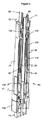
図1は、注射ペンの形の薬物送達デバイス1を示す。このデバイスは、遠位端(図1で上端)および近位端(図1で下端)を有する。薬物送達デバイス1の構成要素部材は、より詳細に図2および図3に示されている。薬物送達デバイス1は、外側ハウジング10、内側本体すなわちシャーシ20、ピストンロッド30、ドライバ40、ナット50、ディスプレイ60、ボタン70、カートリッジ80、ねじりばね90、駆動ナット100、最終用量ナット110、最終用量スリーブ120、移送スリーブ130、用量セレクタ140、およびリターンばね150を含む。ニードルハブおよびニードルカバーがある針配置(図示せず)が、上記で説明したように交換できる追加の構成要素として提供される。
FIG. 1 shows a drug delivery device 1 in the form of an injection pen. The device has a distal end (upper end in FIG. 1) and a proximal end (lower end in FIG. 1). The component members of the drug delivery device 1 are shown in more detail in FIGS. The drug delivery device 1 comprises an
外側ハウジング10は、カートリッジ80を受けるためのカートリッジホルダ11を形成する遠位部分と、投薬機構を受けるための近位部分とを有する概して管状の要素である。好ましい実施形態では、外側ハウジング10は、カートリッジホルダ11の領域、および投薬機構を覆っている外側ハウジング部とカートリッジホルダが結合する中間領域では円形断面を有するのに対して、ハウジング10の近位領域では三角形の断面を有する。したがって、デバイス1を保持し取り扱うのは楽である。窓12が外側ハウジング10に設けられて、ディスプレイ60の細部を見ることが可能になっている。カートリッジホルダ11は、外側ハウジング10付きの単一構成要素部材であるか、または組立て中に外側ハウジング10に取り付けられる別個の構成要素部材である。より詳細に以下で説明するように、外側ハウジング10の一部分は、ドライバ40と共にクラッチを形成する半径方向内向きの歯13を備える。
The
シャーシ20は、外側ハウジング10内で軸方向および回転方向に固定される概して管状の要素である。フランジがばね90の自由端に取り付けられる。さらに、遠位方向に延びる少なくとも1つのスプライン連結フィンガ21が設けられる。図示の実施形態では、ナット50および最終用量ナット110をそれぞれが案内する3つのフィンガ21が設けられる。
The
ピストンロッド30は、駆動ナット100と係合する雄ねじ31を有する細長い要素である。さらに、ピストンロッドは、外側ハウジング10内でピストンロッド30を回転可能に連結するが外側ハウジング10に対するピストンロッド30の軸方向変位は可能にする、スプライン32または同様の位置合わせ手段を含む。支承部33がピストンロッド30の遠位端に設けられる。
The
ドライバ40は、少なくとも部分的にピストンロッド30を囲む概して管状の遠位部分を有する。ドライバの近位部分は直径が小さい。この近位部分は、図示の実施形態では中実の棒であるが、管状もまた可能である。フランジ41がドライバ40の遠位端に設けられる。より詳細に以下で説明するように、フランジは、ドライバを駆動ナット100に連結またはデカップリングするクラッチを形成する遠位向きの歯42を含む。さらに、ドライバを最終用量スリーブ120に連結またはデカップリングするクラッチの一部である歯43が、フランジ41の近位面に設けられる。ドライバ40は、相対回転しないようにするために移送スリーブ130にスプライン連結される。
The
加えて、クラッチがフランジ41の半径方向外面と外側ハウジング10の間に設けられる。図4に示されるように、このクラッチは、ドライバ40上のラチェットフィンガ44、および外側ハウジング10の内面の歯13を用いたラチェットとして形成される。クラッチは、用量設定(用量増大)中の第1の方向の段階的な回転を可能にしているが、ねじりばね90のトルクに耐えるように設計される。クラッチは、使用者がクラッチに打ち勝つことができるように、すなわち設定用量を減らすことができるように、フィンガ44が第1の方向と反対の回転において歯13を乗り越えるよう設計される。
In addition, a clutch is provided between the radially outer surface of the
ナット50が移送スリーブ130とシャーシ20の間に設けられる。ナット50の外部リブが、シャーシ20の内部スプラインと係合する。ナット50の雌ねじが、移送スリーブ130の雄ねじと係合する。代替形態として、スプラインおよびリブをナット50と移送スリーブ130の間の境界面に設けることも、ねじ山をナット50とシャーシ20の間の境界面に設けることもできる。別の代替形態として、ナット50は、たとえば半割ナットとして設計することもできる。さらに、図5a、図5bおよび図11の実施形態では、回転ハードストップ51、52が、移送スリーブ130上の対応する止め具との相互作用のために、ナット50上に設けられる。図5aおよび図7aに示されるように、3つの止め具すなわち溝53がナット50の外面にある。シャーシ20のフィンガ21がこれらの溝53と、ナット50をシャーシ20に対して回転方向に拘束するが相対軸方向運動は可能にして、係合する。
A
ディスプレイ60は、図8〜図10に示された実施形態では、第1のベルト61および第2のベルト62を含み、それぞれがその上に一連の数字または同様の記号を有し、またそれぞれが一連の開口部63および64をそれぞれ有し、これら数字または同様の記号は、開口部の間に等しい間隔の均等な分布で配置される。しかし、開口部63の間と開口部64の間の寸法および/または間隔は異なる。第1のベルト61は、移送スリーブ130上に設けられた駆動歯車134と、2つの回転可能に連結歯車を有する移送歯車セット65と、移送歯車とスプロケットのセット66とによって駆動される。移送歯車セット65の第1の歯車は駆動歯車134と噛み合い、移送歯車セット65の第2の歯車は、移送歯車に回転可能に連結され突起67および第1のベルトの開口部63と係合するスプロケットをさらに含む、移送歯車とスプロケットのセット66の移送歯車と噛み合う。したがって、移送スリーブ130の回転により第1のベルト61がスプールに巻かれる。第2のベルト62は、図示の実施形態では第2のベルト62の開口部64と係合する2つの突起136を有する、移送スリーブ130のスプロケット135によって駆動される。したがって、第2のベルト62は、移送スリーブ130に直接連結される。突起136の間の間隔が開口部64の間の間隔よりもずっと大きいので、移送スリーブ130の連続的な回転は、第2のベルト62の断続的な動きに変換される。
The
両方のベルト61、62が、外側ハウジング10内に固定されているストライカプレート68によって案内される。ストライカプレート68は、ストライカプレート68によって案内されるベルトの部分が外側ハウジング10の円筒形部分の曲率よりも小さい曲率になるように、平坦またはアーチ形の面を有する。ストライカプレート68により、外側ハウジング10は、図9および図10に示される(丸みのある)三角形の形状を有する。図示の実施形態では、第1のベルト61は、概して三角形の閉ループ上のストライカプレート68、および移送歯車およびスプロケットのセット66のスプロケットによって案内される。第2のベルトはさらに、図8および図10に示された、折れた閉ループを形成する適切な手段によって案内することもできる。
Both
ボタン70は、デバイスの近位端を形成し、用量セレクタ140に対する相対回転、および限定された軸方向運動が可能なように用量セレクタ140内に保持される。中心に置かれたステム71が、その遠位端面でドライバ40の近位部の近位端面に当接する。したがって、ボタン70の軸方向運動がドライバ40に直接移送される。
カートリッジ80は、通常はガラスで作ることができる、充填済みのくびれたカートリッジ貯蔵器81を含む。ゴム型栓82またはストッパは、カートリッジ貯蔵器81の近位端にあり、穿孔可能なゴム封止(図示せず)は、他(遠位)端にある。圧着環状金属バンド83が、ゴム封止を適所に保持するために使用される。カートリッジ80は、栓82に当接するピストンロッド30の支承部33によってカートリッジホルダ11の中に入れられる。
The
薬物送達デバイス1は1.5mLカートリッジまたは3.0mLカートリッジを受け入れるものであるが、その設計は、他の薬剤容器のサイズまたは形式を受け入れるようにも適用される。図示のデバイスの実施形態は、カートリッジ80を使用者または医療専門家が交換できないという点で使い捨てになるように設計されている。再使用可能なデバイスの変形物では、カートリッジホルダを着脱可能にすること、およびピストンロッド30の再設定ができるようにすることを要する。
Although the drug delivery device 1 accepts a 1.5 mL cartridge or a 3.0 mL cartridge, the design is also applicable to accept other drug container sizes or formats. The illustrated device embodiment is designed to be disposable in that the
ねじりばね90は2つの自由端を有し、その遠位端がドライバ40のフランジ41に取り付けられ、その近位端が固定シャーシ20のフランジに取り付けられる。したがって、シャーシ20に対するドライバ40の回転によってねじりばね90が緊張し、その蓄積エネルギーが、ドライバ40がシャーシ20に対して回転できるようにすることによって解放される。ねじりばね90は、小用量を投薬するにも十分なトルクをもたらすように、あらかじめ緊張した状態で組み込まれる。代替実施形態では、このばねは、その蓄積エネルギーが満カートリッジの全内容物を投薬するのに十分であるように、あらかじめ負荷がかけられる。
The
駆動ナット100は、ピストンロッド30のねじ山31と係合する雌ねじを有するスリーブ状または円板形の構成要素である。駆動ナット100は、駆動ナット100が自由に回転できるように外側ハウジング10内に保持される。図示の実施形態では、駆動ナット100は、ドライバ40と駆動ナット100の間に置かれるリターンばね150に対する接触面を形成するフランジ101を含む。さらに、歯102がドライバ40の歯42との係合のために設けられる。
The
最終用量ナット110は、ドライバ40とシャーシフィンガ21の間に提供され置かれる。シャーシフィンガ21と最終用量ナット110の間のスプライン連結係合が、最終用量ナット110の軸方向運動を可能にするが、シャーシ20に対する相対回転は阻止する。最終用量ナットは雄ねじ111を備える。さらに、弾性的に変形可能なフィンガ112が最終用量ナット110上に設けられる。図7aは、最終用量ナット110が、1つまたはそれ以上(本実施形態では3つ)の溝状の、軸方向に延びる凹部113によって中断された雄ねじ111を有し、各凹部がシャーシ20のそれぞれのフィンガ21によって案内されることをより詳細に示す。別の凹部114が、ナット50のリブ状の軸方向に延びる突起54を受けるように設計され配置される。
A
最終用量スリーブ120は、最終用量ナット110およびナット50と協働して、カートリッジ80内に残っている液体の量を超える用量を設定しないようにするための最終用量機構を形成する。最終用量スリーブ120は、最終用量ナット110の雄ねじ111と係合する雌ねじ121を有する、中空の構成要素である。最終用量スリーブ120の遠位端面は、最終用量スリーブ120をドライバ40に回転可能に連結するためにフランジ41の近位面に設けられた歯43と相互作用する歯122を備える。
移送スリーブ130は、ドライバ40に回転方向に拘束されるように、しかしドライバに対する相対軸方向運動は可能にするようにドライバ40にスプライン連結される管状要素である。上述のように、移送スリーブ130は、ねじ山131および回転止め具132、133を備えた遠位部分を有する。さらに、移送スリーブ130は、第1のベルト61を駆動するための歯車134と、第2のベルト62を駆動するための突起136が付いたスプロケット135とを備える。移送スリーブ130の段付き部分は、移送スリーブ130に対するドライバ40の軸方向運動が近位方向に限定されるように、ドライバ40の直径の変化に対応する。図5aおよび図5bは、最終用量ナット110と相互作用するように移送スリーブ130上に設けられた鋸歯止め具要素137を示す。
The
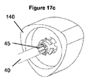
用量セレクタ140は、外側ハウジング10の近位部の外形に対応する三角形の外形を有する。用量セレクタ140は、ボタン70のステム71を案内しドライバ40の近位端を受ける内側スリーブ141を含む。図14および図15に示されるように、ドライバ40の近位端は、用量セレクタの内側案内輪郭と係合するスプライン45を有する。
The
リターンばね150は、駆動ナット100のフランジ101とドライバ40のフランジ41との間に置かれる圧縮ばねである。したがって、リターンばね150はドライバ40を近位方向に付勢する。ボタン70が使用者によって押された場合、ドライバ40は、リターンばね150の付勢に抗して遠位方向に動く。
The
以下では、使い捨て薬物送達デバイス1の機能およびその構成要素について、より詳細に説明する。 Below, the function of the disposable drug delivery device 1 and its components will be described in more detail.
このデバイスを使用するには、使用者は用量を選択しなければならない。図1〜図3および図16a〜図16cに示された開始(静止)状態では、ねじりばね90は、使用者が最小用量を選択した場合にデバイスがその最小用量を送達できるように、あらかじめ加えられた十分な負荷を有する。静止時に用量インジケータベルト61、62は、用量が選択されていないことを示す0または同等のマーキングを表示する。
To use this device, the user must select a dose. In the starting (resting) state shown in FIGS. 1-3 and 16a-16c, the
プライミングショットおよび/または安全ショットが注射の前に必要とされる。プライミングとは、初めて使用するデバイスを準備する行為である。既存のペン注射器では、これは、1つまたはそれ以上の小用量を設定し、空中に放出することを意味し、それにより、デバイスの「遊び」(あらゆる隙間)および公差が除去され、また各構成要素が適切な圧縮または緊張の状態に置かれるようになる。安全ショットでは、使用者が注射の前ごとに1つまたはそれ以上の小用量を設定し空中に放出して、針が詰まっていないことを確実にする。 A priming shot and / or a safety shot is required prior to injection. Priming is an act of preparing a device to be used for the first time. In existing pen syringes, this means setting one or more small doses and releasing them into the air, thereby eliminating device “play” (any gaps) and tolerances, and each The component will be placed in proper compression or tension. In a safety shot, the user sets and releases one or more small doses into the air before each injection to ensure that the needle is not clogged.
使用者は、用量セレクタ140を回転させることによって用量を設定する。用量セレクタ140を回転させるとドライバ40が回転し、あらかじめ加える負荷がねじりばね90に加わる。移送スリーブ130は、ドライバ40にスプライン連結され、使用者が用量セレクタ140をダイヤル設定するときにディスプレイ60の用量数機構を割り出しする。
The user sets the dose by rotating the
図4は、ドライバ40上のラチェット機能41を示し、これは、外側ハウジング10の内面のスプライン13と係合して、用量セレクタ140がねじりばねトルクによりその初期位置まで回転して戻らないようにする。これらのラチェット機能13、41は、使用者が注射ボタン70を完全に押し下げたときに係合解除する。
FIG. 4 shows a
使用者が、用量セレクタ140を回転させることによって、したがってドライバ40および移送スリーブ130を回転させることによって、用量を設定するとナット50は、フィンガ21および溝53に案内されて軸方向に移動する。同時に、最終用量ナット110は、フィンガ21および凹部113に案内されて軸方向に移動する。ナット50と移送スリーブ130とのねじ係合、および最終用量ナット110と最終用量スリーブ120とのねじ係合は、使用者が用量を増大した場合にはナット50が最終用量ナット110に接近し、使用者が用量を減らした場合にはこれらが互いに離れるようなものである。フィンガ112は、応力がかからないその位置では、移送スリーブ130上に設けられた止め具要素137に干渉しないように位置する。
When the user sets the dose by rotating the
最小用量(0IU)および最大用量(たとえば120IU)の制限が、移送スリーブ130上の機能132、133に干渉し、したがってさらなる相対回転を阻止するナット50上のハードストップ機能によって設けられる。図5aおよび図5bは、ナット50を中間位置で、すなわち約60IUがダイヤル設定された状態で示す。
Minimum dose (0 IU) and maximum dose (eg, 120 IU) limits are provided by a hard stop function on the
最終用量保護が、使用者がカートリッジ80内の使用可能量を超える用量を設定することを阻止する。用量設定中、ドライバ40は、歯43および122を介して最終用量スリーブ120と係合する。カートリッジ容積が120単位未満に減少したときには、最終用量ナット110は、ナット50に干渉できる位置まで動いている。使用者がその残り分より多い用量をダイヤル設定しようとすると、ナット50は、最終用量ナット110上の可撓性機能、すなわちフィンガ112を、それが移送スリーブ130上の段状のスプライン機能137と係合して回転ハードストップを形成するように曲げる。図7aおよび図7bは、この最終用量機構の係合の直前のデバイスを示す。フィンガ112を内向きに曲げて止め具要素137の1つを係合するこの工程は、突起54の内面がフィンガ112を押すようにして突起54が凹部114に入るよう最終用量ナット110に接近する、ナット50によって開始される。フィンガ112が止め具要素137の1つと係合するとすぐに、設定用量を増大する方向に最終用量ナット110がさらに回転することが防止される。最終用量ナット110が、次に駆動スリーブ40と連結されてから移送スリーブ130を介して用量セレクタ140に連結される最終用量スリーブ120とねじ係合されているので、用量設定機構全体が阻止され、それによって、使用者が選択できる用量が制限される。しかし、反対の動き、すなわち用量を減らすことが依然として可能である。加えて、設定された用量は、フィンガ112が止め具要素137と係合していても、完全に投与することができる。
Final dose protection prevents the user from setting a dose that exceeds the usable amount in the
用量数は、用量セレクタ140が回転するにつれて増大または減少する。これは、対応する数字ベルト61を割り出しするスプロケット66への変速装置65と係合する、移送スリーブ130内の平歯車機能134によって達成される。第2の数字ベルト62は、移送スリーブ130上の第2の機能(突起136)を追加の変速装置に連結することによって、または第2のベルト62に直接連結することによって、割り出しされる。図8〜図10に示された実施形態では、第1の数字ベルト61は、数字「0」から「9」を各2つ備え、第2の数字ベルト62は、その上に数字「0」から「12」を有する。第2のベルト62上の「0」の代わりに、空白を設けることもできる。言い換えると、用量セレクタ140が完全に1回転するごとに、第1のベルト61(1の位単位カウンタベルト)は完全な1回転を行って、数字「0」から「9」を2回表示する。同時に、第2のベルト62(10単位カウンタベルト)は2つの位置で、すなわち、たとえば空白から「1」まで、および「1」から「2」まで断続的に動く。ゼロ単位ダイヤル設定から開始して、用量セレクタ140が完全に1回転すると、第2のベルト62で「2」、第1のベルト61で「0」を示す表示が得られ、その結果、ベルト61および62が合わさって「20」を表示するようになる。
The number of doses increases or decreases as the
注射ボタン70が押し下げられると、図16a〜図16c(ボタン70解放)を図17a〜図17c(ボタン70押し下げ)と比較して理解される以下の動作が行われる。
When the
ドライバ40は、注射ボタン70によって前方に動き、最終用量スリーブ120から係合解除する。したがって、最終用量保護ナット110は、注射中ずっと固定されたままである。さらに、ドライバ40は、リターンばね150を圧縮し始め、クラッチ歯42、102を介して親ねじ駆動ナット100と係合する。この時点で、ドライバ40は依然としてエネルギー蓄積ラチェット13、41と係合していて、ねじりばね90の巻き戻しを防止する。ドライバ40は、今や注射用量またはダイヤル設定用量に影響を及ぼすことなく自由に回転できる用量セレクタ140から係合解除する。最後の1mmくらいにわたって、ドライバ40は駆動ナット100と完全に係合し、エネルギー蓄積ラチェット13、41から離脱する。ねじりばね90は、巻き戻り始めてドライバ40を回転させ、次にドライバが駆動ナット100を回転させる。駆動ナット100が、デバイス外側ハウジング10にスプライン連結されているピストンロッド30(親ねじ)を回転させると、ピストンロッドは前方に動いて薬剤を投薬する。
The
用量中断および用量分割が可能である。注射ボタン70にかかる軸方向の力が除去された場合、ボタン70はリターンばね150の作用を受けて、その初期の軸方向位置まで用量セレクタ140に対して戻る。これにより、ドライバ40上のラチェット41が外側ハウジング10のスプライン13と係合することが可能になり、それによって、ねじりばね90の駆動トルクによるそれ以上の注射が防止される。さらには、これによりドライバ40が用量セレクタ140および最終用量スリーブ120と係合され、それによって、用量セレクタ140が再び回転することが可能になる。この時点で、用量セレクタ140は、以下で説明するように、外側ハウジング10と再び位置が合う。用量は、用量セレクタ140を回転させることによって変えることができ、ボタン70を押し下げると注射操作が再開する。
Dose interruptions and dose splits are possible. When the axial force on the
注射中、ねじりばね90は巻き戻ってドライバ40が回転する。これにより、用量数機構は、「0」に向かって数を逆に数えるように割り出しされる。同時に、ナット50は、その「0」位置に向かって後退する。ナット50がこの位置に達すると、使用者には用量の終わりを知らせる「クリック音」が聞こえ、場合によっては知覚される。これは、図11および図12に示されるわずかな戻り止め干渉による、互いに通り過ぎるナット40と移送スリーブ130両方の上の機能によって実現される。
During injection, the
この例示的な実施形態は、非軸対称外側ハウジング10および用量セレクタ140を有し、これは、用量設定中に用量セレクタ140が外側ハウジング10に対して位置が合わなくなることを意味する。図13aおよび図13bはそれぞれ、位置が合っている用量セレクタ140、および位置が合っていない用量セレクタ140を示す。これには技法的問題は何もないが、使用者は、それぞれの注射の終わりには用量セレクタ140が外側ハウジング10と再び位置が合うことを好む可能性がある。したがってデバイスは、使用者がボタン70を解放したときに用量セレクタ140をデバイス外側ハウジング10と再位置合わせする機構を含む。図14および図15に示されるように、使用者がボタンを解放すると、ドライバ40はその「0」位置まで軸方向に戻る。ドライバ40が用量セレクタ140と接触するようになると、ドライバ40上の雄位置合わせ機能(スプライン45)は、用量セレクタ140内にある対応する雌螺旋機能142と係合し始める。これにより、用量セレクタ140は、ドライバ40と完全に係合するまで回転する。次に用量セレクタ140は、外側ハウジング10と完全に位置合わせされる。
This exemplary embodiment has a non-axisymmetric
最終用量保護を達成するためにねじ付ナットまたは半割ナット機構を使用する他の多くのペン注射器と同様に、本発明の用量リミッタは、たとえば300IUの3ml、U100インスリンカートリッジであるカートリッジの容積全体にわたって作動する。最終用量保護ナットは、使用者が用量をダイヤル設定するときに前進する。カートリッジ内に残っている、最大設定可能用量未満の、たとえば120IUのインスリン配合物がある場合、最終用量保護ナットは制限ナットと係合して、移送スリーブと共に回転式または軸方向のハードストップを形成する。 Like many other pen syringes that use a threaded nut or half nut mechanism to achieve final dose protection, the dose limiter of the present invention is an entire cartridge volume, for example, a 300 IU 3 ml, U100 insulin cartridge. Operate over. The final dose protection nut advances when the user dials the dose. If there is less than the maximum settable dose, eg 120 IU of insulin formulation remaining in the cartridge, the final dose protection nut engages the limiting nut to form a rotary or axial hard stop with the transfer sleeve To do.
Claims (16)
液体を収容するカートリッジ(80)と、
用量選択中に回転する投薬要素(40、130)と、
該投薬要素(40、130)の回転が最終用量ナット(110)の軸方向運動を引き起こすように用量選択中に投薬要素(40、130)に連結される最終用量ナット(110)と、
カートリッジ(80)内に残っている液体の量に対応する用量が選択された場合に最終用量ナット(110)のそれ以上の動きを阻止する止め具要素(137)と
を含み、
ここで、止め具要素(137)は投薬要素(40、130)上に設けられ、用量リミッタはさらに、用量選択中には投薬要素(40、130)に回転可能に連結され用量投薬中には投薬要素(40、130)から回転方向にデカップリングされる最終用量スリーブ(120)を含み、最終用量ナット(110)は、最終用量スリーブ(120)によって投薬要素(40、130)に連結される、前記薬物送達デバイス。 A drug delivery device having a dose limiter to prevent setting a dose that exceeds the amount of liquid remaining in the cartridge of the drug delivery device , comprising:
A cartridge (80) for accommodating the liquids,
A dosing element (40, 130) that rotates during dose selection;
A final dose nut (110) coupled to the dose element (40, 130) during dose selection such that rotation of the dose element (40, 130) causes axial movement of the final dose nut (110);
A stop element (137) that prevents further movement of the final dose nut (110) when a dose corresponding to the amount of liquid remaining in the cartridge (80) is selected;
Here, the stop element (137) is provided on the dosing element (40, 130) and the dose limiter is further rotatably connected to the dosing element (40, 130) during dose selection and during dose dosing. The final dose sleeve (120) is decoupled in a rotational direction from the dosing element (40, 130), and the final dose nut (110) is connected to the dosing element (40, 130) by the final dose sleeve (120). The drug delivery device.
Applications Claiming Priority (3)
| Application Number | Priority Date | Filing Date | Title |
|---|---|---|---|
| EP13176887 | 2013-07-17 | ||
| EP13176887.1 | 2013-07-17 | ||
| PCT/EP2014/065342 WO2015007823A1 (en) | 2013-07-17 | 2014-07-17 | Drug delivery device |
Publications (2)
| Publication Number | Publication Date |
|---|---|
| JP2016524980A JP2016524980A (en) | 2016-08-22 |
| JP6480924B2 true JP6480924B2 (en) | 2019-03-13 |
Family
ID=48795459
Family Applications (1)
| Application Number | Title | Priority Date | Filing Date |
|---|---|---|---|
| JP2016526631A Expired - Fee Related JP6480924B2 (en) | 2013-07-17 | 2014-07-17 | Drug delivery device |
Country Status (7)
| Country | Link |
|---|---|
| US (1) | US10195356B2 (en) |
| EP (1) | EP3021910B1 (en) |
| JP (1) | JP6480924B2 (en) |
| CN (1) | CN105377343B (en) |
| DK (1) | DK3021910T3 (en) |
| HK (1) | HK1219681A1 (en) |
| WO (1) | WO2015007823A1 (en) |
Families Citing this family (5)
| Publication number | Priority date | Publication date | Assignee | Title |
|---|---|---|---|---|
| JP6932644B2 (en) * | 2015-04-29 | 2021-09-08 | ノボ・ノルデイスク・エー/エス | Drug delivery device with a spring mechanism |
| PL227678B1 (en) | 2015-12-22 | 2018-01-31 | Copernicus Spolka Z Ograniczona Odpowiedzialnoscia | Control and drive system for the device intended for injection and the device for making injections equipped with such a system |
| PL3108914T3 (en) | 2016-07-07 | 2019-08-30 | Copernicus Sp. Z O.O. | Injection device for delivering a defined number of equal doses of a liquid substance |
| US10688247B2 (en) * | 2017-07-13 | 2020-06-23 | Haselmeier Ag | Injection device with flexible dose selection |
| PL232651B1 (en) | 2017-07-18 | 2019-07-31 | Copernicus Spolka Z Ograniczona Odpowiedzialnoscia | Coupling with locking system for the medical injecting device |
Family Cites Families (11)
| Publication number | Priority date | Publication date | Assignee | Title |
|---|---|---|---|---|
| TW453884B (en) | 1999-09-16 | 2001-09-11 | Novo Nordisk As | Dose setting limiter |
| GB0304822D0 (en) | 2003-03-03 | 2003-04-09 | Dca Internat Ltd | Improvements in and relating to a pen-type injector |
| CN101107032B (en) | 2005-01-25 | 2010-09-29 | 诺和诺德公司 | An injection device with an end of dose feedback mechanism |
| DE102008011885A1 (en) | 2008-02-29 | 2009-09-10 | Tecpharma Licensing Ag | Dual function spring |
| US8647309B2 (en) * | 2008-05-02 | 2014-02-11 | Sanofi-Aventis Deutschland Gmbh | Medication delivery device |
| JP5805092B2 (en) * | 2009-09-30 | 2015-11-04 | サノフィ−アベンティス・ドイチュラント・ゲゼルシャフト・ミット・ベシュレンクテル・ハフツング | Injection device |
| AR078457A1 (en) * | 2009-09-30 | 2011-11-09 | Sanofi Aventis Deutschland | DRIVING MECHANISM FOR A DRUG DISCHARGE DEVICE |
| WO2011068531A1 (en) * | 2009-12-01 | 2011-06-09 | Becton, Dickinson And Company | Injection pen with dial back and last dose control |
| CN103547304B (en) * | 2011-03-24 | 2016-08-17 | Shl集团有限责任公司 | Delivery device |
| CA2838809A1 (en) * | 2011-07-15 | 2013-01-24 | Stephen Francis GILMORE | A drug delivery device |
| EP2830685B1 (en) * | 2012-03-30 | 2017-05-31 | Tecpharma Licensing AG | Injection device with a dose display element displaceable relative to a housing. |
-
2014
- 2014-07-17 DK DK14739471.2T patent/DK3021910T3/en active
- 2014-07-17 JP JP2016526631A patent/JP6480924B2/en not_active Expired - Fee Related
- 2014-07-17 US US14/905,382 patent/US10195356B2/en not_active Expired - Fee Related
- 2014-07-17 CN CN201480040314.2A patent/CN105377343B/en not_active Expired - Fee Related
- 2014-07-17 EP EP14739471.2A patent/EP3021910B1/en active Active
- 2014-07-17 WO PCT/EP2014/065342 patent/WO2015007823A1/en active Application Filing
-
2016
- 2016-06-30 HK HK16107615.2A patent/HK1219681A1/en unknown
Also Published As
| Publication number | Publication date |
|---|---|
| US20160136358A1 (en) | 2016-05-19 |
| JP2016524980A (en) | 2016-08-22 |
| US10195356B2 (en) | 2019-02-05 |
| EP3021910B1 (en) | 2020-05-27 |
| HK1219681A1 (en) | 2017-04-13 |
| DK3021910T3 (en) | 2020-08-17 |
| EP3021910A1 (en) | 2016-05-25 |
| CN105377343A (en) | 2016-03-02 |
| WO2015007823A1 (en) | 2015-01-22 |
| CN105377343B (en) | 2019-04-05 |
Similar Documents
| Publication | Publication Date | Title |
|---|---|---|
| JP6314139B2 (en) | Drug delivery device | |
| JP6359635B2 (en) | Injection device | |
| JP6310057B2 (en) | Dosing rate control mechanism and injection device | |
| JP6419159B2 (en) | Injection device | |
| JP6395809B2 (en) | Injection device | |
| JP6404323B2 (en) | Injection device | |
| JP2016518185A (en) | Automatic drug injection device with sophisticated drive mechanism | |
| JP6412569B2 (en) | Drug delivery device | |
| JP2017520369A (en) | Injection device with torsion spring attached and method of assembling the same | |
| JP2016514588A (en) | Injection device and assembly method | |
| JP6465861B2 (en) | Handheld drug injection device and dose setting limiter mechanism therefor | |
| JP2017520370A (en) | Spring arrangement and drug delivery device having spring arrangement | |
| JP6395808B2 (en) | Injection device | |
| JP6722102B2 (en) | Medication rate control mechanism and injection device | |
| JP2016514587A (en) | Injection device | |
| JP2017536959A (en) | Drug delivery device | |
| JP2017530803A (en) | Housing and drug delivery device having the same | |
| JP2016526995A (en) | Drug delivery device | |
| JP6480924B2 (en) | Drug delivery device | |
| JP2016518181A (en) | Automatic drug injection device having a reverse wound spring spring drive mechanism | |
| JP2016514602A (en) | Injection device | |
| TW201618821A (en) | Drive sleeve, drug delivery device and method for assembling a drug delivery device | |
| JP2017530798A (en) | Housing and drug delivery device having housing | |
| JP2017535359A (en) | Drug delivery device having dose setting mechanism and ratchet mechanism | |
| JP2017520368A (en) | An injection device including a compression spring for engaging the ratchet element, urging the actuation button, and urging the locking element into the dose setting mode |
Legal Events
| Date | Code | Title | Description |
|---|---|---|---|
| A621 | Written request for application examination |
Free format text: JAPANESE INTERMEDIATE CODE: A621 Effective date: 20170705 |
|
| A131 | Notification of reasons for refusal |
Free format text: JAPANESE INTERMEDIATE CODE: A131 Effective date: 20180529 |
|
| A977 | Report on retrieval |
Free format text: JAPANESE INTERMEDIATE CODE: A971007 Effective date: 20180525 |
|
| A521 | Request for written amendment filed |
Free format text: JAPANESE INTERMEDIATE CODE: A523 Effective date: 20180822 |
|
| TRDD | Decision of grant or rejection written | ||
| A01 | Written decision to grant a patent or to grant a registration (utility model) |
Free format text: JAPANESE INTERMEDIATE CODE: A01 Effective date: 20190129 |
|
| A61 | First payment of annual fees (during grant procedure) |
Free format text: JAPANESE INTERMEDIATE CODE: A61 Effective date: 20190208 |
|
| R150 | Certificate of patent or registration of utility model |
Ref document number: 6480924 Country of ref document: JP Free format text: JAPANESE INTERMEDIATE CODE: R150 |
|
| LAPS | Cancellation because of no payment of annual fees |