JP6421781B2 - Heat exchanger - Google Patents
Heat exchanger Download PDFInfo
- Publication number
- JP6421781B2 JP6421781B2 JP2016085417A JP2016085417A JP6421781B2 JP 6421781 B2 JP6421781 B2 JP 6421781B2 JP 2016085417 A JP2016085417 A JP 2016085417A JP 2016085417 A JP2016085417 A JP 2016085417A JP 6421781 B2 JP6421781 B2 JP 6421781B2
- Authority
- JP
- Japan
- Prior art keywords
- core plate
- joint
- plate
- heat exchanger
- bottom plate
- Prior art date
- Legal status (The legal status is an assumption and is not a legal conclusion. Google has not performed a legal analysis and makes no representation as to the accuracy of the status listed.)
- Expired - Fee Related
Links
Images


Classifications
-
- F—MECHANICAL ENGINEERING; LIGHTING; HEATING; WEAPONS; BLASTING
- F28—HEAT EXCHANGE IN GENERAL
- F28D—HEAT-EXCHANGE APPARATUS, NOT PROVIDED FOR IN ANOTHER SUBCLASS, IN WHICH THE HEAT-EXCHANGE MEDIA DO NOT COME INTO DIRECT CONTACT
- F28D1/00—Heat-exchange apparatus having stationary conduit assemblies for one heat-exchange medium only, the media being in contact with different sides of the conduit wall, in which the other heat-exchange medium is a large body of fluid, e.g. domestic or motor car radiators
- F28D1/02—Heat-exchange apparatus having stationary conduit assemblies for one heat-exchange medium only, the media being in contact with different sides of the conduit wall, in which the other heat-exchange medium is a large body of fluid, e.g. domestic or motor car radiators with heat-exchange conduits immersed in the body of fluid
- F28D1/04—Heat-exchange apparatus having stationary conduit assemblies for one heat-exchange medium only, the media being in contact with different sides of the conduit wall, in which the other heat-exchange medium is a large body of fluid, e.g. domestic or motor car radiators with heat-exchange conduits immersed in the body of fluid with tubular conduits
- F28D1/053—Heat-exchange apparatus having stationary conduit assemblies for one heat-exchange medium only, the media being in contact with different sides of the conduit wall, in which the other heat-exchange medium is a large body of fluid, e.g. domestic or motor car radiators with heat-exchange conduits immersed in the body of fluid with tubular conduits the conduits being straight
- F28D1/0535—Heat-exchange apparatus having stationary conduit assemblies for one heat-exchange medium only, the media being in contact with different sides of the conduit wall, in which the other heat-exchange medium is a large body of fluid, e.g. domestic or motor car radiators with heat-exchange conduits immersed in the body of fluid with tubular conduits the conduits being straight the conduits having a non-circular cross-section
- F28D1/05366—Assemblies of conduits connected to common headers, e.g. core type radiators
-
- F—MECHANICAL ENGINEERING; LIGHTING; HEATING; WEAPONS; BLASTING
- F28—HEAT EXCHANGE IN GENERAL
- F28F—DETAILS OF HEAT-EXCHANGE AND HEAT-TRANSFER APPARATUS, OF GENERAL APPLICATION
- F28F9/00—Casings; Header boxes; Auxiliary supports for elements; Auxiliary members within casings
- F28F9/001—Casings in the form of plate-like arrangements; Frames enclosing a heat exchange core
-
- F—MECHANICAL ENGINEERING; LIGHTING; HEATING; WEAPONS; BLASTING
- F28—HEAT EXCHANGE IN GENERAL
- F28F—DETAILS OF HEAT-EXCHANGE AND HEAT-TRANSFER APPARATUS, OF GENERAL APPLICATION
- F28F9/00—Casings; Header boxes; Auxiliary supports for elements; Auxiliary members within casings
- F28F9/02—Header boxes; End plates
- F28F9/0219—Arrangements for sealing end plates into casing or header box; Header box sub-elements
- F28F9/0224—Header boxes formed by sealing end plates into covers
- F28F9/0226—Header boxes formed by sealing end plates into covers with resilient gaskets
-
- F—MECHANICAL ENGINEERING; LIGHTING; HEATING; WEAPONS; BLASTING
- F28—HEAT EXCHANGE IN GENERAL
- F28D—HEAT-EXCHANGE APPARATUS, NOT PROVIDED FOR IN ANOTHER SUBCLASS, IN WHICH THE HEAT-EXCHANGE MEDIA DO NOT COME INTO DIRECT CONTACT
- F28D21/00—Heat-exchange apparatus not covered by any of the groups F28D1/00 - F28D20/00
- F28D2021/0019—Other heat exchangers for particular applications; Heat exchange systems not otherwise provided for
- F28D2021/008—Other heat exchangers for particular applications; Heat exchange systems not otherwise provided for for vehicles
- F28D2021/0091—Radiators
- F28D2021/0094—Radiators for recooling the engine coolant
-
- F—MECHANICAL ENGINEERING; LIGHTING; HEATING; WEAPONS; BLASTING
- F28—HEAT EXCHANGE IN GENERAL
- F28F—DETAILS OF HEAT-EXCHANGE AND HEAT-TRANSFER APPARATUS, OF GENERAL APPLICATION
- F28F2265/00—Safety or protection arrangements; Arrangements for preventing malfunction
- F28F2265/26—Safety or protection arrangements; Arrangements for preventing malfunction for allowing differential expansion between elements
Description
この明細書における開示は、複数のチューブがタンクに接続された熱交換器に関する。 The disclosure in this specification relates to a heat exchanger in which a plurality of tubes are connected to a tank.
特許文献1−4は、熱交換器を開示する。熱交換器は、複数のチューブが接続されるプレートを有する。このプレートは、チューブプレートまたはコアプレートといった多様な呼び名で呼ばれる。この明細書では、コアプレートの名称を用いる。 Patent documents 1-4 disclose a heat exchanger. The heat exchanger has a plate to which a plurality of tubes are connected. This plate is called by various names such as tube plate or core plate. In this specification, the name of the core plate is used.
熱交換器においては、複数のチューブなどの部材における温度差に起因する伸縮量の差に起因して、部材または接合部の変形または破損が生じることが知られている。このような現象は、熱歪で呼ばれている。 In heat exchangers, it is known that deformation or breakage of members or joints occurs due to differences in expansion and contraction due to temperature differences among members such as a plurality of tubes. Such a phenomenon is called thermal strain.
特許文献1−3は、コアプレートの両端部に熱歪が表れることを開示する。さらに、特許文献1−3は、コアプレートの形状、または端部の補強プレートの形状による改良を提案している。特許文献4は、コアプレートの四隅に、スリット状の切り込みを形成している。 Patent Documents 1-3 disclose that thermal strain appears at both ends of the core plate. Further, Patent Documents 1-3 propose improvements based on the shape of the core plate or the shape of the reinforcing plate at the end. In Patent Document 4, slit-shaped cuts are formed at four corners of the core plate.
熱交換器には、熱歪に対して高い耐性を発揮することが求められている。例えば、媒体の温度変化が大きいシステム、媒体の流量変化が大きいシステムでは、熱交換器に大きい温度差が生じることがある。このような観点において、従来技術は熱歪に対する十分な対策を提供していない。上述の観点において、または言及されていない他の観点において、熱交換器にはさらなる改良が求められている。 Heat exchangers are required to exhibit high resistance to thermal strain. For example, in a system with a large change in the temperature of the medium and a system with a large change in the flow rate of the medium, a large temperature difference may occur in the heat exchanger. From this point of view, the prior art does not provide a sufficient countermeasure against thermal distortion. In view of the above, or other aspects not mentioned, there is a need for further improvements in heat exchangers.
開示されるひとつの目的は、熱歪が抑制された熱交換器を提供することである。 One object disclosed is to provide a heat exchanger with reduced thermal strain.
開示される熱交換器は、長さ方向(LD)に沿って細長いコアプレート(6)と、端部がコアプレートに接合された複数のチューブ(7)と、コアプレートの端部に設けられた接合部(BR)においてコアプレートと接合された補強プレート(9)とを有する。コアプレートは、複数のチューブが接合された底板(21)と、底板から延び出しており、長さ方向に沿って広がる側壁(22)と、側壁の縁から側壁の高さ方向(HD)に沿って延びるように側壁に形成され、接合部と最初のチューブ(7a)との間のエンド領域(ER)の中に位置しており、コアプレートの変形を可能とするサイド変形可能部(41、741)と、複数のチューブを受け入れ、複数のチューブと接合されるために底板に形成された隆起部(26)と、コアプレートの幅方向(WD)に沿って隆起部を横切って延びるように底板に形成され、接合部と最初のチューブ(7a)との間のエンド領域(ER)の中に位置しており、コアプレートとタンクカバー(5)との間に配置されるシール部材(27)が接触するシール面(25)の上の空洞に幅方向のサイド開口が連通しているリブ(45、845)とを有する。 The disclosed heat exchanger includes an elongated core plate (6) along a length direction (LD), a plurality of tubes (7) whose ends are joined to the core plate, and an end of the core plate. And a reinforcing plate (9) joined to the core plate at the joint (BR). The core plate has a bottom plate (21) to which a plurality of tubes are joined, a side wall (22) extending from the bottom plate along the length direction, and from the edge of the side wall to the side wall height direction (HD). A side deformable portion (41) which is formed on the side wall so as to extend along the end region (ER) between the joint portion and the first tube (7a) and allows deformation of the core plate. 741), and a ridge (26) formed in the bottom plate for receiving and joining the plurality of tubes, and extending across the ridge along the width direction (WD) of the core plate A sealing member (between the core plate and the tank cover (5)), which is located in the end region (ER) between the joint and the first tube (7a). 27) Sealing surface that contacts Cavity in the width direction of the side opening on the 25) and a rib (45,845) in communication.
開示される熱交換器によると、サイド変形可能部は、接合部と最初のチューブとの間のエンド領域の中においてコアプレートの変形を可能とする。複数のチューブと補強プレートとの間における温度差に起因して伸縮量に差が生じることがある。この場合、サイド変形可能部は、コアプレートの変形を促すことによってコアプレートとチューブとの接合部における歪を抑制する。 According to the disclosed heat exchanger, the side deformable part allows the deformation of the core plate in the end region between the joint and the first tube. A difference in the amount of expansion and contraction may occur due to a temperature difference between the plurality of tubes and the reinforcing plate. In this case, the side deformable portion suppresses distortion at the joint portion between the core plate and the tube by promoting deformation of the core plate.
開示される熱交換器は、長さ方向(LD)に沿って細長いコアプレート(6)と、端部がコアプレートに接合された複数のチューブ(7)と、コアプレートの端部に設けられた接合部(BR)においてコアプレートと接合された補強プレート(9)とを備えており、コアプレートは、複数のチューブが接合された底板(21)と、底板から延び出しており、長さ方向に沿って広がる側壁(22)と、側壁の縁から側壁の高さ方向(HD)に沿って延びるように側壁に形成され、接合部と最初のチューブ(7a)との間のエンド領域(ER)の中に位置しており、コアプレートの変形を可能とするサイド変形可能部(41、741、941)と、底板から延び出しており、コアプレートの端部に位置し、接合部が設けられた端壁(23)と、接合部の両側において、端壁の縁から端壁の高さ方向(HD)に沿って接合部を越えて延びるように端壁に形成され、それらの間に底板から延び出すとともに接合部を有する接合片(28)を区画形成し、接合片の変形を可能とするエンド変形可能部(43、743)とを有する。
開示される熱交換器は、長さ方向(LD)に沿って細長いコアプレート(6)と、端部がコアプレートに接合された複数のチューブ(7)と、コアプレートの端部に設けられた接合部(BR)においてコアプレートと接合された補強プレート(9)とを有する。コアプレートは、複数のチューブが接合された底板(21)と、複数のチューブを受け入れ、複数のチューブと接合されるために底板に形成された隆起部(26)と、コアプレートの幅方向(WD)に沿って隆起部を横切って延びるように底板に形成され、接合部と最初のチューブ(7a)との間のエンド領域(ER)の中に位置しており、コアプレートとタンクカバー(5)との間に配置されるシール部材(27)が接触するシール面(25)の上の空洞に幅方向のサイド開口が連通しているリブ(45、845)と、底板から延び出しており、コアプレートの端部に位置し、接合部が設けられた端壁(23)と、接合部の両側において、端壁の縁から端壁の高さ方向(HD)に沿って接合部を越えて延びるように端壁に形成され、それらの間に底板から延び出すとともに接合部を有する接合片(28)を区画形成し、接合片の変形を可能とするエンド変形可能部(43、743)とを有する。
The disclosed heat exchanger includes an elongated core plate (6) along a length direction (LD), a plurality of tubes (7) whose ends are joined to the core plate, and an end of the core plate. And a reinforcing plate (9) joined to the core plate at the joint (BR). The core plate extends from the bottom plate (21) to which a plurality of tubes are joined, and has a length. A side wall (22) extending along the direction, and an end region (between the joint and the first tube (7a)) formed on the side wall so as to extend from the edge of the side wall along the side wall height direction (HD). ER), the side deformable portions (41, 741, 941) that allow the deformation of the core plate and the bottom plate, are located at the end of the core plate, and the joint is The provided end wall (23) The joint is formed on the end wall so as to extend beyond the joint along the height direction (HD) of the end wall from the edge of the end wall on both sides of the joint, and extends from the bottom plate therebetween and has the joint The piece (28) is partitioned and has an end deformable portion (43, 743) that enables deformation of the joining piece.
The disclosed heat exchanger includes an elongated core plate (6) along a length direction (LD), a plurality of tubes (7) whose ends are joined to the core plate, and an end of the core plate. And a reinforcing plate (9) joined to the core plate at the joint (BR). The core plate includes a bottom plate (21) to which a plurality of tubes are joined, a raised portion (26) formed on the bottom plate to receive the plurality of tubes and to be joined to the plurality of tubes, and a width direction of the core plate ( WD) is formed in the bottom plate so as to extend across the ridge along the WD, and is located in the end region (ER) between the joint and the first tube (7a), the core plate and the tank cover ( 5) and a rib (45, 845) in which a side opening in the width direction communicates with a cavity above the seal surface (25) with which the seal member (27) disposed between the two extends and extends from the bottom plate The end wall (23) located at the end of the core plate and provided with the joint, and the joint on the both sides of the joint from the edge of the end wall along the height direction (HD) of the end wall. Formed on the end walls to extend beyond them Joining pieces having a joint portion with extending out from the bottom plate (28) is defined and formed between, and an end deformable section (43,743) to allow deformation of the joining pieces.
開示される熱交換器によると、リブは、接合部と最初のチューブとの間のエンド領域の中においてコアプレートの変形を可能とする。複数のチューブと補強プレートとの間における温度差に起因して伸縮量に差が生じることがある。この場合、リブは、コアプレートの変形を促すことによってコアプレートとチューブとの接合部における歪を抑制する。 According to the disclosed heat exchanger, the ribs allow deformation of the core plate in the end region between the joint and the initial tube. A difference in the amount of expansion and contraction may occur due to a temperature difference between the plurality of tubes and the reinforcing plate. In this case, the rib suppresses distortion at the joint between the core plate and the tube by urging deformation of the core plate.
開示される熱交換器は、長さ方向(LD)に沿って細長いコアプレート(6)と、端部がコアプレートに接合された複数のチューブ(7)と、コアプレートの端部に設けられた接合部(BR)においてコアプレートと接合された補強プレート(9)とを有する。コアプレートは、複数のチューブが接合された底板(21)と、底板から延び出しており、コアプレートの端部に位置し、接合部が設けられた端壁(23)と、接合部の両側において、端壁の縁から端壁の高さ方向(HD)に沿って接合部を越えて延びるように端壁に形成され、それらの間に底板から延び出すとともに接合部を有する接合片(28)を区画形成し、接合片の変形を可能とするエンド変形可能部(43、743)とを有する。 The disclosed heat exchanger includes an elongated core plate (6) along a length direction (LD), a plurality of tubes (7) whose ends are joined to the core plate, and an end of the core plate. And a reinforcing plate (9) joined to the core plate at the joint (BR). The core plate has a bottom plate (21) to which a plurality of tubes are joined, extends from the bottom plate, is located at an end of the core plate, is provided with an end wall (23) provided with a joint, and both sides of the joint A joint piece (28) formed on the end wall so as to extend from the edge of the end wall along the height direction (HD) of the end wall beyond the joint, and extending from the bottom plate therebetween and having the joint ) And an end deformable portion (43, 743) that enables deformation of the joining piece.
開示される熱交換器によると、エンド変形可能部は、コアプレートと補強プレートとの間の接合部を提供する接合片の変形を可能とする。複数のチューブと補強プレートとの間における温度差に起因して伸縮量に差が生じることがある。この場合、エンド変形可能部は、接合片の変形を促すことによってコアプレートとチューブとの接合部における歪を抑制する。 According to the disclosed heat exchanger, the end deformable portion allows deformation of the joining piece that provides a joint between the core plate and the reinforcing plate. A difference in the amount of expansion and contraction may occur due to a temperature difference between the plurality of tubes and the reinforcing plate. In this case, the end deformable portion suppresses distortion at the joint portion between the core plate and the tube by urging deformation of the joint piece.
この明細書における開示された複数の態様は、それぞれの目的を達成するために、互いに異なる技術的手段を採用する。請求の範囲およびこの項に記載した括弧内の符号は、後述する実施形態の部分との対応関係を例示的に示すものであって、技術的範囲を限定することを意図するものではない。この明細書に開示される目的、特徴、および効果は、後続の詳細な説明、および添付の図面を参照することによってより明確になる。 The disclosed embodiments of the present specification employ different technical means to achieve each purpose. The reference numerals in parentheses described in the claims and this section exemplify the correspondence with the embodiments described later, and are not intended to limit the technical scope. The objects, features, and advantages disclosed in this specification will become more apparent with reference to the following detailed description and accompanying drawings.
図面を参照しながら、複数の実施形態を説明する。複数の実施形態において、機能的におよび/または構造的に対応する部分および/または関連付けられる部分には同一の参照符号、または3桁の最上位桁が異なる参照符号が付される場合がある。対応する部分および/または関連付けられる部分については、他の実施形態の説明を参照することができる。 A plurality of embodiments will be described with reference to the drawings. In some embodiments, functionally and / or structurally corresponding and / or associated parts may be assigned the same reference signs or different reference signs with three most significant digits. For the corresponding parts and / or associated parts, the description of other embodiments can be referred to.
第1実施形態
図1において、熱交換器1は、第1媒体が循環的に流れる媒体回路11の一部を提供している。媒体回路11は、熱源装置(HD)12を含む。熱源装置12において発生した熱は、第1媒体によって運ばれる。熱交換器1は、第1媒体を流すための通路を区画形成している。熱交換器1は、第1媒体と第2媒体との間の熱交換を提供する。熱交換器1は、例えば、車両に搭載される車両用熱交換器である。熱源装置12は、例えば、車両の動力用内燃機関、動力用電動機、インバータなどの冷却を要する機器である。第1媒体は、例えば、冷却水である。第2媒体は、例えば、大気である。
First Embodiment In FIG. 1, a
熱交換器1は、一対のタンク部2、3および、これらタンク部2、3の間に設けられたコア部4を有する。タンク部2、3は、第1媒体を複数の通路へ分配する分配部および複数の通路から第1媒体を集める集合部を提供する。図示の例では、タンク部2は、入口タンクを提供する。タンク部3は、出口タンクを提供する。コア部4は、第1媒体のための複数の通路と、第2媒体のための複数の通路とを区画形成する。
The
熱交換器1は、タンク部2、3を提供するタンクカバー5、およびコアプレート6を有する。タンクカバー5とコアプレート6とは、シール部材を介して連結されることによりタンク部2、3を形成する。コアプレート6は、タンクカバー5の開口端を受け入れる凹部と、タンクカバー5を係止するように曲げられた複数のフック部とを有する。タンクカバー5とコアプレート6とは、コアプレート6の縁に設けられた複数のフック部によって連結されている。熱交換器1は、2つのタンクカバー5と、2つのコアプレート6とを有する。
The
熱交換器1は、コア部4を提供する複数のチューブ7と、複数のアウタフィン8とを有する。コアプレート6は、コア部4を形成する部材のひとつと考えられてもよい。複数のチューブ7と複数のアウタフィン8とは、コア部4を形成するように配列されている。複数のチューブ7は、所定の間隔をもって配列されている。複数のチューブ7は、コアプレート6の長さ方向に沿って互いに平行に配置されている。複数のチューブ7の間には、第2媒体のための通路が区画形成されている。チューブ7は、その内部に第1媒体のための通路を形成する。アウタフィン8は、隣接する2つのチューブ7の間に配置されている。アウタフィン8は、チューブ7に接触している。アウタフィン8は、第2媒体の通路の中に配置されている。アウタフィン8は、チューブ7と第2媒体との熱交換面積を拡大するために貢献する。アウタフィン8は、熱交換促進部材とも呼ばれる。
The
複数のチューブ7は、コアプレート6に接合されている。チューブ7の一端は、一方のコアプレート6に接合されている。チューブ7の他端は、他方のコアプレート6に接合されている。チューブ7とコアプレート6とは、チューブ7内の通路が、タンク部2、3の内部に連通するように接合されている。図示の例では、チューブ7の端部は、コアプレート6を貫通するように挿し込まれている。
The plurality of
熱交換器1は、補強プレート9を有する。熱交換器1は、2つの補強プレート9を有する。補強プレート9は、コア部4の両端に設けられている。補強プレート9は、2つのコアプレート6を連結している。補強プレート9は、最も端のアウタフィン8と連結されている。言い換えると、アウタフィン8が、チューブ7と補強プレート9との間に設けられている。
The
タンクカバー5は、例えば、樹脂製である。コアプレート6、チューブ7、アウタフィン8、および補強プレート9は、銅、アルミニウムなどの金属製である。コアプレート6、チューブ7、アウタフィン8、および補強プレート9は、接合部材によって接合されている。接合部材は、例えば、ろう材である。複数のチューブ7は、その両端部において、コアプレート6に接合されている。複数のアウタフィン8は、少なくともひとつのチューブ7に接合されている。補強プレート9は、その両端部において2つのコアプレート6に接合されている。
The
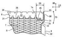
図2、図3、図4、図5、および図6において、熱交換器1の隅部が図示されている。図3は、図2における矢印IIIから見た平面図である。図4は、図2における矢印IVから見た側面図である。図5は、図4のV−V線における断面図である。図6は、図4のVI−VI線における断面図である。図中においては、コアプレート6の深さがやや強調されて描かれている。
In FIG. 2, FIG. 3, FIG. 4, FIG. 5, and FIG. FIG. 3 is a plan view seen from an arrow III in FIG. FIG. 4 is a side view seen from the arrow IV in FIG. 5 is a cross-sectional view taken along line VV in FIG. 6 is a cross-sectional view taken along line VI-VI in FIG. In the drawing, the depth of the
以下の説明では、理解を容易にするために、図2における上を上方と呼び、下を下方と呼ぶ。高さ方向HDは、チューブ7の長手方向に対応する。多くの場合、高さは、シール面25から上方向への高さを指す。長さ方向LDは、コアプレート6の長手方向に対応する。幅方向WDは、コアプレート6の長手方向と直交する方向(短手方向)に対応する。多くの場合、深さは、当該部位の上から下、または下から上への深さを指す。なお、上下などの空間的な語は、熱交換器1の実際の設置状態を表すものではない。
In the following description, in order to facilitate understanding, the upper side in FIG. 2 is referred to as the upper side, and the lower side is referred to as the lower side. The height direction HD corresponds to the longitudinal direction of the
図2および図3において、コアプレート6は、長さ方向LDに沿って細長い。コアプレート6は、浅い皿状である。コアプレート6は、細長い長方形の底板21を有する。コアプレート6は、底板21の少なくとも四辺に設けられた側壁22および端壁23を有する。
2 and 3, the
底板21は、複数のチューブ7と接合されている。底板21は、複数のチューブ7を受け入れるための複数の貫通穴を有する。底板21は、複数のチューブ7を受け入れるために適した形状を与えられている。底板21は、複数のチューブ7との接合に適した形状を与えられている。
The
2つの側壁22は、底板21の長辺に設けられている。側壁22は、底板21から延び出しており、長さ方向LDに沿って広がっている。2つの端壁23は、底板21の短辺に設けられている。端壁23は、底板21から延び出している。端壁23は、コアプレート6の端部に位置している。端壁23には、接合部BRが設けられている。底板21と側壁22および端壁23との間には、丸い角部が形成されている。側壁22と端壁23との間には、丸い角部が形成されている。側壁22および端壁23の縁には、複数のフック部24が形成されている。これらフック部24は、タンクカバー5を係止するように曲げられる。図中には、フック部24が曲げられる前の形状が図示されている。
The two
底板21は、側壁22および端壁23に沿って延びるシール面25を有する。シール面25は、側壁22および端壁23に沿って環状に延びている。
The
図5には、シール部材27が図示されている。シール面25は、シール部材27と接触する。シール部材27は、シール面25に沿って配置されている。シール部材27は、シール面25とタンクカバー5の開口端とに接触する。
FIG. 5 shows the
図2および図3に戻り、底板21は、隆起部26を有する。隆起部26は、コアプレート6の内側に向けて隆起している。隆起部26は、複数のチューブ7を受け入れ、複数のチューブ7と接合されるために適した形状を底板21に形成する。隆起部26は、チューブ7を受け入れるための貫通穴と凹部とを提供する。隆起部26は、底板21の中央部に形成されている。シール面25は、隆起部26を囲むように延びている。
Returning to FIGS. 2 and 3, the
端壁23は、補強プレート9と接合される第1接合片28を提供する。第1接合片28は、底板21に直接的に連続している。第1接合片28は、底板21から延び出す板片である。
The
補強プレート9は、コアプレート6の端部に設けられた接合部BRにおいてコアプレート6と接合されている。補強プレート9は、端壁23または第1接合片28と接合される第2接合片31を有する。補強プレート9は、コア部4に沿って延びている端壁部32を有する。端壁部32は、断面コ字型である。補強プレート9は、第2接合片31と端壁部32とを連結する連結部33を有する。連結部33は、端壁部32の長手方向に対して交差するように延びている。連結部33は、補強プレート9の長手方向における長さを調節可能な調節部でもある。
The reinforcing
図4に図示されるように、第1接合片28と第2接合片31とは、接合部BRにおいて接合部材によって接合されている。接合部BRは、底板21から離れて位置づけられている。
As illustrated in FIG. 4, the first joining
図2および図3において、コアプレート6は、サイド変形可能部を有する。サイド変形可能部は、2つのサイドスリット41、41によって提供されている。サイドスリット41、41は、両方の側壁22、22に設けられている。サイドスリット41は、コアプレート6の端部におけるエンド領域ERの中に位置づけられている。言い換えると、サイドスリット41は、エンド領域ERの中であって、かつ側壁22の平面領域の中に設けられている。エンド領域ERは、接合部BRと、端から最初のチューブ7aとの間に対応している。最初のチューブ7aとコアプレート6との接合部には比較的大きい歪が生じる。
2 and 3, the
サイドスリット41は、側壁22を貫通している。サイドスリット41は、側壁22の高さ方向HDに真っ直ぐに延びている。サイドスリット41は、側壁22の縁から、底板21と側壁22との境界の角部に到達している。サイドスリット41は、側壁22の縁から、シール面25に到達する深いスリットである。サイドスリット41が形成された部分には、側壁22がない。サイドスリット41の幅は、エンド領域ERの幅より小さい。サイドスリット41は、側壁22と端壁23との間の角部を残すように位置づけられている。
The side slit 41 passes through the
図5および図6に図示されるように、サイドスリット41は、側壁22を長さ方向LDに関して分断している。サイドスリット41は、分断スリットとも呼ばれる。この結果、コアプレート6は、サイドスリット41に起因して、矢印TDの曲げ方向に関して変形しやすくなる。矢印TDの曲げ方向は、コアプレート6の長さ方向LDに関して、コアプレート6の端部を高さ方向HDへ変位させる方向である。複数のチューブ7と補強プレート9との間に大きい温度差が生じる場合、伸縮量の差に起因して、コアプレート6とチューブ7との間に、歪が発生することがある。この場合、コアプレート6はサイドスリット41においてしなやかに変形し、コアプレート6とチューブ7との間における歪を抑制する。
As shown in FIGS. 5 and 6, the side slit 41 divides the
サイド変形可能部は、側壁22の縁から側壁22の高さ方向HDに沿って延びるように側壁22に形成されている。サイド変形可能部は、接合部BRと最初のチューブ7aとの間のエンド領域ERの中に位置している。サイド変形可能部は、コアプレート6の変形を可能とする。サイドスリット41は、コアプレート6における変形を生じやすくする変形促進部とも呼ぶことができる。サイドスリット41は、幅方向WDに延びる線上における変形を生じやすくする。サイドスリット41は、コアプレート6の剛性を部分的に低下させる低剛性部とも呼ぶことができる。サイドスリット41は、コアプレート6上に相対的に強度的に弱い部分を形成するから、脆弱部とも呼ぶことができる。
The side deformable portion is formed on the
図3および図4において、コアプレート6は、エンド変形可能部を有する。エンド変形可能部は、2つのエンドスリット43、43によって提供されている。エンドスリット43、43は、端壁23に設けられている。エンドスリット43は、第1接合片28の両側に設けられている。エンドスリット43は、端壁23の中に第1接合片28を区画している。言い換えると、第1接合片28は、エンドスリット43によって区画形成されている。エンドスリット43は、接合部BRの両側に設けられている。
3 and 4, the
エンドスリット43は、端壁23を貫通している。エンドスリット43は、端壁23の高さ方向HDに真っ直ぐに延びている。エンドスリット43は、端壁23の縁から、接合部BRを越えて下方向へ延びている。エンドスリット43は、端壁23の縁から、底板21と端壁23との境界の角部に到達している。エンドスリット43は、端壁23の縁から、シール面25に到達する深いスリットである。エンドスリット43の幅は、第1接合片28の幅より小さい。エンドスリット43は、側壁22と端壁23との間の角部を残すように位置づけられている。
The end slit 43 passes through the
エンドスリット43は、端壁23から第1接合片28を分離させている。この結果、第1接合片28は、底板21から高さ方向HDに延び出す独立した舌片として形成される。これにより、第1接合片28は、図5に図示される矢印TDの方向に関して変形しやすくなる。言い換えると、第1接合片28は、倒れるように変形しやすい。この結果、第1接合片28は、しなやかに変形し、コアプレート6とチューブ7との間における歪を抑制する。
The end slit 43 separates the first joining
エンド変形可能部は、接合部BRの両側において、端壁23の縁から端壁23の高さ方向HDに沿って接合部BRを越えて延びるように端壁23に形成されている。2つのエンド変形可能部は、それらの間に底板21から延び出すとともに接合部BRを有する第1接合片28を区画形成している。エンド変形可能部は、第1接合片28の長さ方向LDおよび高さ方向HDにおける変形、すなわち倒れを可能とする。エンドスリット43は、第1接合片28の比較的自由な変形を生じやすくする変形促進部とも呼ぶことができる。エンドスリット43は、長さ方向LDおよび高さ方向HDにおける第1接合片28の変形を可能とする。エンドスリット43は、コアプレート6の剛性を部分的に低下させる低剛性部とも呼ぶことができる。エンドスリット43は、コアプレート6上に相対的に強度的に弱い部分を形成するから、脆弱部とも呼ぶことができる。
The end deformable portions are formed on the
図3、図5、および図6において、コアプレート6は、リブ45を有する。リブ45は、底板21に設けられている。リブ45は、隆起部26の中に設けられている。リブ45は、コアプレート6の内側において、凹形状である。リブ45は、コアプレート6の内側、すなわちタンク部2、3の内部側に向けて開いたU字状断面を有する。リブ45は、隆起部26の中に隆起部26より低い部位を提供する。リブ45は、コアプレート6を幅方向WDに沿って横断するように延びている。リブ45は、側壁22から側壁22へ向かう幅方向WDに沿って延びている。リブ45は、エンド領域ERの範囲内に位置づけられている。
3, 5, and 6, the
リブ45は、隆起部26を横断している。リブ45は、上向きの上部開口と、横向きのサイド開口とを有する。上部開口は、隆起部26の上に細長く開口している。サイド開口は、隆起部26の側面に開口している。リブ45内の空洞は、幅方向WDに関して真っ直ぐに、サイド開口を経由して、シール面25の上の空洞に連通している。リブ45は、隆起部26の両側においてシール面25の上の空洞に開口している。リブ45内の空洞は、その両端においてシール面25上の空洞に連通している。なお、シール面25の上の空洞には、シール部材27とタンクカバー5とが配置される。
The
リブ45の底は、シール面25と同じ高さに位置している。よって、リブ45は、リブ45の底面と、シール面25とが平面として連続するように形成されている。リブ45は、底板21の上に、隆起部26のような凸部をもたない平面部を提供する。
The bottom of the
図示されるように、リブ45は、隆起部26を長さ方向LDに関して分断している。リブ45は、分断リブとも呼ばれる。この結果、コアプレート6は、リブ45に起因して、矢印TDの方向に関して変形しやすくなる。コアプレート6はリブ45においてしなやかに変形し、コアプレート6とチューブ7との間における歪を抑制する。
As illustrated, the
リブ45は、コアプレート6の幅方向WDに沿って隆起部26を横切って延びるように底板21に形成されている。リブ45は、接合部BRと最初のチューブ7aとの間のエンド領域ERの中に位置している。リブ45は、コアプレート6とタンクカバー5との間に配置されるシール部材27が接触するシール面25の上の空洞に幅方向WDの端部が連通している。リブ45は、コアプレート6における変形を生じやすくする変形促進部とも呼ぶことができる。リブ45は、幅方向WDに延びる線上における変形を引き起こすから、線状変形促進部とも呼ぶことができる。リブ45は、コアプレート6の剛性を部分的に低下させる低剛性部とも呼ぶことができる。リブ45は、コアプレート6上に相対的に強度的に弱い部分を形成するから、脆弱部とも呼ぶことができる。
The
図示されるように、サイドスリット41とリブ45とは、エンド領域ERの中に位置付けられている。しかも、サイドスリット41とリブ45とは、長さ方向LDにおける同じ位置に設けられている。これにより、コアプレート6はサイドスリット41およびリブ45の位置において変形しやすい。
As illustrated, the side slit 41 and the
以上に述べた実施形態によると、接合部BRと、端から最初のチューブ7aとの間に、サイドスリット41およびリブ45が設けられる。これにより、サイドスリット41およびリブ45の位置においてコアプレート6の剛性が抑制される。これにより、コアプレート6は、サイドスリット41およびリブ45の位置においてしなやかに変形することができる。よって、コアプレート6とチューブ7との間における歪が抑制される。コアプレート6は、第1接合片28の両側に深いエンドスリット43、43を有する。これにより、第1接合片28は倒れるように変形することができる。よって、コアプレート6とチューブ7との間における歪が抑制される。
According to the embodiment described above, the side slits 41 and the
第2実施形態
この実施形態は、先行する実施形態を基礎的形態とする変形例である。図8は、図7のVIII−VIII線における断面図である。図7および図8において、コアプレート6は、サイドスリット41を有する。コアプレート6は、エンドスリット43およびリブ45を備えない。この実施形態でも、サイドスリット41によってコアプレート6とチューブ7との間における歪が抑制される。
Second Embodiment This embodiment is a modified example based on the preceding embodiment. 8 is a cross-sectional view taken along line VIII-VIII in FIG. 7 and 8, the
第3実施形態
この実施形態は、先行する実施形態を基礎的形態とする変形例である。図10は、図9のX−X線における断面図である。図9および図10において、コアプレート6は、エンドスリット43を有する。コアプレート6は、サイドスリット41およびリブ45を備えない。この実施形態でも、エンドスリット43によってコアプレート6とチューブ7との間における歪が抑制される。
Third Embodiment This embodiment is a modification in which the preceding embodiment is a basic form. 10 is a cross-sectional view taken along line XX in FIG. 9 and 10, the
第4実施形態
この実施形態は、先行する実施形態を基礎的形態とする変形例である。図12は、図11のXII−XII線における断面図である。図11および図12において、コアプレート6は、リブ45を有する。コアプレート6は、サイドスリット41およびエンドスリット43を備えない。この実施形態でも、リブ45によってコアプレート6とチューブ7との間における歪が抑制される。
Fourth Embodiment This embodiment is a modified example based on the preceding embodiment. 12 is a cross-sectional view taken along line XII-XII in FIG. 11 and 12, the
第5実施形態
この実施形態は、先行する実施形態を基礎的形態とする変形例である。上記実施形態では、第1接合片28は、端壁23と平行に位置している。これに代えて、第1接合片28は多様な形状をもつことができる。例えば、第1接合片28は、端壁23から独立して変形しやすい形状をもつことができる。
Fifth Embodiment This embodiment is a modified example based on the preceding embodiment. In the above embodiment, the first joining
図13において、コアプレート6は、第1接合片528を有する。第1接合片528は、エンドスリット43によって区画形成されている。第1接合片528は、底板21と接合部BRとの間に傾斜部29を有する。傾斜部29は、第1接合片528を端壁23より外側に位置付ける。傾斜部29は、矢印TDの方向において第1接合片528を変形しやすくする。傾斜部29は、変形促進部とも呼ばれる。この実施形態によると、傾斜部29によって第1接合片528の変形が促進される。よって、コアプレート6とチューブ7との間における歪が抑制される。
In FIG. 13, the
第6実施形態
この実施形態は、先行する実施形態を基礎的形態とする変形例である。上記実施形態では、第1接合片28、528と第2接合片31との間の接合は、平板と平板との間の接合によって提供されている。これに代えて、多様な接合形状を採用することができる。例えば、端壁23の一部と、補強プレート9とを機械的に噛み合わせる機械的な連結と、接合部材による接合とを併用してもよい。
Sixth Embodiment This embodiment is a modification in which the preceding embodiment is a basic form. In the said embodiment, joining between the 1st joining
図14において、コアプレート6は、第1接合片628を有する。第1接合片628は、第2接合片31を機械的に係止するクリップ部として形成されている。クリップ部は、第2接合片31を内部に収容するU字状断面の部分によって提供されている。クリップ部は、第1接合片628を折曲げることによって形成されている。クリップ部は、第2接合片31に機械的に噛みあっている。クリップ部は、接合工程の前における、第1接合片628と第2接合片31との連結を可能とする。さらに、第1接合片628と第2接合片31との間は、接合部材によって接合されている。この実施形態によると、コアプレート6と補強プレート9との強固な連結が得られる。さらに、先行する実施形態と同様の作用効果が得られる。
In FIG. 14, the
第7実施形態
この実施形態は、先行する実施形態を基礎的形態とする変形例である。上記実施形態では、図3に図示されるように、サイドスリット41、およびエンドスリット43は、シール面25に到達している。また、リブ45の底面は、シール面25に到達している。これに代えて、スリットは、シール面25に到達しない程度のやや浅い深さを有していてもよい。また、リブは、シール面25に到達しない程度のやや浅い深さを有していてもよい。図16は、図15のXVI−XVI線における断面図である。図17は、図16のXVII−XVII線における断面図である。
Seventh Embodiment This embodiment is a modified example based on the preceding embodiment. In the above embodiment, as shown in FIG. 3, the side slit 41 and the end slit 43 reach the
図15、図16、および図17において、コアプレート6は、サイドスリット741を有する。サイドスリット741の深さは、サイドスリット41の深さより浅い。サイドスリット741は、底板21と側壁22との間の曲がり部、すなわち角部に到達しない深さを有している。サイドスリット741は、側壁22の縁から、隆起部26の高さに到達する深さを有する。浅いサイドスリット741は、そのサイドスリット741におけるコアプレート6の変形を容易にするが、シール面25およびシール部材27を収容する凹部の変形を抑制する。
15, 16, and 17, the
コアプレート6は、エンドスリット743を有する。エンドスリット743は、エンドスリット743の深さは、エンドスリット43の深さより浅い。エンドスリット743は、底板21と側壁22との間の曲がり部、すなわち角部に到達しない深さを有している。エンドスリット743は、側壁22の縁から、接合部BRの両側をとおり、接合部BRより下に到達する深さを有する。エンドスリット743の幅は、エンドスリット43の幅より細い。エンドスリット743の幅は、第1接合片28の変形しやすさに影響しないから、比較的自由な設定が可能である。エンドスリット743は、第1接合片28を倒れるように変形可能に形成しながら、シール面25およびシール部材27を収容する凹部の変形を抑制する。
The
コアプレート6は、リブ745を有する。リブ745の深さは、リブ45の深さより浅い。リブ745の底部は、シール面25に到達しない。リブ745の両端と、シール面25との間には、コアプレート6の内側に向けて凸となる肩部745aが形成されている。肩部745aの曲面は、隆起部26における肩部26aの曲面より小さい曲率を有する。言い換えると、肩部745aの曲面は、肩部26aの曲面よりなだらかである。肩部745aは、シール部材27のリブ745内へ向かう変形を抑制する。
The
サイドスリット741の長さ方向LDにおける幅は、リブ745の長さ方向LDにおける幅と等しい。これらの幅の範囲において、コアプレート6は、矢印TDの方向へ変形しやすい。リブ745は、リブ745におけるコアプレート6の変形を容易にするが、シール面25およびシール部材27を収容する凹部の変形を抑制する。この実施形態でも、コアプレート6とチューブ7との間における歪が抑制される。
The width of the side slit 741 in the length direction LD is equal to the width of the
第8実施形態
この実施形態は、先行する実施形態を基礎的形態とする変形例である。先行する実施形態では、リブ45は、U字状断面を有している。これに代えて、リブ45は多様な断面形状を有することができる。図18において、コアプレート6は、リブ845を有する。リブ845は、V字状断面を有している。リブ845は、先行する実施形態のリブ45に代えて用いることができる。この実施形態でも、リブ845によってコアプレート6とチューブ7との間における歪が抑制される。
Eighth Embodiment This embodiment is a modification example based on the preceding embodiment. In the preceding embodiment, the
第9実施形態
この実施形態は、先行する実施形態を基礎的形態とする変形例である。上記実施形態では、サイドスリット41、741によってサイド変形可能部を形成している。これに代えて、サイド変形可能部は、多様な形状によって提供することができる。例えば、列状に配置された複数の貫通穴によってサイド変形可能部を提供することができる。また、側壁22に設けられたU字状、S字状などの湾曲部によってサイド変形可能部を提供することができる。
Ninth Embodiment This embodiment is a modification example based on the preceding embodiment. In the above embodiment, the side deformable portion is formed by the side slits 41 and 741. Alternatively, the side deformable part can be provided in various shapes. For example, the side deformable portion can be provided by a plurality of through holes arranged in a row. Further, the side deformable portion can be provided by a curved portion such as a U shape or an S shape provided on the
図19は、サイド変形可能部941を示す斜視図である。図中には、エンド領域ERにおける底板21と側壁22とが図示されている。サイド変形可能部941は、底板21と側壁22とにわたって形成された貫通穴941aを有する。貫通穴941aは、底板21と側壁22との間の角部に位置づけられている。サイド変形可能部941は、側壁22の縁から高さ方向HDに沿って延びる湾曲部941bを有する。湾曲部941bは、縁と貫通穴941aとの間にわたって設けられている。湾曲部941bは、高さ方向HDに沿って延びる峰と谷とを形成している。湾曲部941bは、コアプレート6の外側に向けて突出している。この実施形態によると、貫通穴941aと湾曲部941bとがコアプレート6の変形を可能とする。これにより、コアプレート6とチューブ7との間における歪が抑制される。
FIG. 19 is a perspective view showing the side
他の実施形態
この明細書における開示は、例示された実施形態に制限されない。開示は、例示された実施形態と、それらに基づく当業者による変形態様を包含する。例えば、開示は、実施形態において示された部品および/または要素の組み合わせに限定されない。開示は、多様な組み合わせによって実施可能である。開示は、実施形態に追加可能な追加的な部分をもつことができる。開示は、実施形態の部品および/または要素が省略されたものを包含する。開示は、ひとつの実施形態と他の実施形態との間における部品および/または要素の置き換え、または組み合わせを包含する。開示される技術的範囲は、実施形態の記載に限定されない。開示されるいくつかの技術的範囲は、特許請求の範囲の記載によって示され、さらに特許請求の範囲の記載と均等の意味及び範囲内での全ての変更を含むものと解されるべきである。
Other Embodiments The disclosure herein is not limited to the illustrated embodiments. The disclosure encompasses the illustrated embodiments and variations by those skilled in the art based thereon. For example, the disclosure is not limited to the combinations of parts and / or elements shown in the embodiments. The disclosure can be implemented in various combinations. The disclosure may have additional parts that can be added to the embodiments. The disclosure includes those in which parts and / or elements of the embodiments are omitted. The disclosure encompasses the replacement or combination of parts and / or elements between one embodiment and another. The technical scope disclosed is not limited to the description of the embodiments. Some technical scope disclosed is indicated by the description of the claims, and should be understood to include all modifications within the meaning and scope equivalent to the description of the claims. .
上記実施形態では、エンド領域ERの中に、サイドスリット41、741、およびリブ45、745、845の少なくともひとつを設けている。これに代えて、ひとつのサイドスリット41、741に代わる複数のサイドスリットを設けてもよい。また、エンド領域ERの外に追加的なスリットを設けてもよい。例えば、複数のチューブ7が配置されている領域において、側壁22にスリットが設けられていてもよい。例えば、複数のチューブ7が配置されている領域において、底板21にリブが設けられていてもよい。また、サイドスリット41、741とリブ45、745、845との組は、エンド領域ERの外に追加的に設けられてもよい。
In the above embodiment, at least one of the side slits 41 and 741 and the
上記実施形態では、サイドスリット41、741とリブ45、745、845との組は、コアプレート6の長さ方向LDにおける同じ位置に配置されている。これに代えて、組をなすサイドスリット41、741とリブ45、745、845とは、コアプレート6の長さ方向LDにおいてずれて配置されてもよい。
In the above embodiment, the set of the side slits 41 and 741 and the
上記実施形態では、補強プレート9は、コアプレート6の外側面に接合されている。これに代えて、補強プレート9は、チューブ7のようにコアプレート6に挿入され、機械的に連結され、および/または接合されてもよい。
In the above embodiment, the reinforcing
上記実施形態では、サイドスリット41、741およびエンドスリット43、743は、まっすぐの直線状のスリットによって提供されている。これに代えて、円弧状、S字状、クランク状など多様な形状のスリットを採用することができる。 In the said embodiment, the side slits 41 and 741 and the end slits 43 and 743 are provided by the straight linear slit. Instead of this, slits having various shapes such as an arc shape, an S shape, and a crank shape can be employed.
上記実施形態では、サイドスリット41、741およびエンドスリット43、743は、側壁22の縁から底板21と側壁22との境界の角部まで到達している。これに代えて、サイドスリット41、741およびエンドスリット43、743の深さが、チューブ7と補強プレート9との間に大きな温度差が生じた場合にコアプレート6が変形可能な深さであればよい。言い換えると、サイドスリット41、741およびエンドスリット43、743の深さは、コアプレート6の変形を許容できる深さである。
In the above-described embodiment, the side slits 41 and 741 and the end slits 43 and 743 reach the corner portion of the boundary between the
上記実施形態では、隆起部26を横断する連続したリブ45、745、845を設けている。これに代えて、リブ45、745、845の中に、部分的な隆起部が設けられていてもよい。この場合、リブは、複数の部分に分断される。この形状でも、底板21は、リブが形成されている部位において変形しやすい。
In the above embodiment,
1 熱交換器、 2、3 タンク部、 4 コア部、
5 タンクカバー、 6 コアプレート、 7 チューブ、
7a 最初のチューブ、 8 アウタフィン、 9 補強プレート、
11 媒体回路、 12 熱源装置、
21 底板、 22 側壁、 23 端壁、 24 フック部、
25 シール面、 26 隆起部、 27 シール部材、
28、528、628 第1接合片、 29 傾斜部、
31 第2接合片、 32 端壁部、 33 連結部、
41、741 サイドスリット(サイド変形可能部)、941 サイド変形可能部、
43、743 エンドスリット(エンド変形可能部)、
45、745、845 リブ、
BR 接合部、 ER エンド領域。
1 heat exchanger, 2, 3 tank part, 4 core part,
5 Tank cover, 6 Core plate, 7 Tube,
7a First tube, 8 Outer fin, 9 Reinforcement plate,
11 Medium circuit, 12 Heat source device,
21 bottom plate, 22 side wall, 23 end wall, 24 hook part,
25 sealing surface, 26 raised portion, 27 sealing member,
28, 528, 628 first joining piece, 29 inclined portion,
31 2nd joining piece, 32 End wall part, 33 Connection part,
41, 741 Side slit (side deformable portion), 941 Side deformable portion,
43, 743 End slit (end deformable part),
45, 745, 845 ribs,
BR junction, ER end region.
Claims (14)
端部が前記コアプレートに接合された複数のチューブ(7)と、
前記コアプレートの端部に設けられた接合部(BR)において前記コアプレートと接合された補強プレート(9)とを備えており、
前記コアプレートは、
複数の前記チューブが接合された底板(21)と、
前記底板から延び出しており、前記長さ方向に沿って広がる側壁(22)と、
前記側壁の縁から前記側壁の高さ方向(HD)に沿って延びるように前記側壁に形成され、前記接合部と最初のチューブ(7a)との間のエンド領域(ER)の中に位置しており、前記コアプレートの変形を可能とするサイド変形可能部(41、741、941)と、
複数の前記チューブを受け入れ、複数の前記チューブと接合されるために前記底板に形成された隆起部(26)と、
前記コアプレートの幅方向(WD)に沿って前記隆起部を横切って延びるように前記底板に形成され、前記接合部と最初のチューブ(7a)との間のエンド領域(ER)の中に位置しており、前記コアプレートとタンクカバー(5)との間に配置されるシール部材(27)が接触するシール面(25)の上の空洞に前記幅方向のサイド開口が連通しているリブ(45、845)とを有する熱交換器。 An elongated core plate (6) along the length direction (LD);
A plurality of tubes (7) whose ends are joined to the core plate;
A reinforcing plate (9) joined to the core plate at a joint (BR) provided at an end of the core plate;
The core plate is
A bottom plate (21) to which a plurality of the tubes are joined;
A side wall (22) extending from the bottom plate and extending along the length direction;
It is formed on the side wall so as to extend from the edge of the side wall along the height direction (HD) of the side wall, and is located in an end region (ER) between the joint and the first tube (7a). Side deformable portions (41, 741, 941) that allow deformation of the core plate ;
A ridge (26) formed in the bottom plate for receiving a plurality of the tubes and joining the plurality of tubes;
Formed in the bottom plate to extend across the ridge along the width direction (WD) of the core plate and located in the end region (ER) between the joint and the first tube (7a) A rib in which the side opening in the width direction communicates with a cavity above a sealing surface (25) with which a sealing member (27) disposed between the core plate and the tank cover (5) contacts. (45, 845) .
前記底板から延び出しており、前記コアプレートの端部に位置し、前記接合部が設けられた端壁(23)と、
前記接合部の両側において、前記端壁の縁から前記端壁の高さ方向(HD)に沿って前記接合部を越えて延びるように前記端壁に形成され、それらの間に前記底板から延び出すとともに前記接合部を有する接合片(28)を区画形成し、前記接合片の変形を可能とするエンド変形可能部(43、743)とを有する請求項1から請求項5のいずれかに記載の熱交換器。 The core plate is
An end wall (23) extending from the bottom plate, located at an end of the core plate and provided with the joint;
On both sides of the joint, the end wall extends from the edge of the end wall along the height direction (HD) of the end wall beyond the joint, and extends from the bottom plate therebetween. joining piece (28) is defined and formed with the joining portion together with issue, according to any one of claims 1 to 5 having an end deformable section (43,743) to allow deformation of the joining piece Heat exchanger.
端部が前記コアプレートに接合された複数のチューブ(7)と、
前記コアプレートの端部に設けられた接合部(BR)において前記コアプレートと接合された補強プレート(9)とを備えており、
前記コアプレートは、
複数の前記チューブが接合された底板(21)と、
前記底板から延び出しており、前記長さ方向に沿って広がる側壁(22)と、
前記側壁の縁から前記側壁の高さ方向(HD)に沿って延びるように前記側壁に形成され、前記接合部と最初のチューブ(7a)との間のエンド領域(ER)の中に位置しており、前記コアプレートの変形を可能とするサイド変形可能部(41、741、941)と、
前記底板から延び出しており、前記コアプレートの端部に位置し、前記接合部が設けられた端壁(23)と、
前記接合部の両側において、前記端壁の縁から前記端壁の高さ方向(HD)に沿って前記接合部を越えて延びるように前記端壁に形成され、それらの間に前記底板から延び出すとともに前記接合部を有する接合片(28)を区画形成し、前記接合片の変形を可能とするエンド変形可能部(43、743)とを有する熱交換器。 An elongated core plate (6) along the length direction (LD);
A plurality of tubes (7) whose ends are joined to the core plate;
A reinforcing plate (9) joined to the core plate at a joint (BR) provided at an end of the core plate;
The core plate is
A bottom plate (21) to which a plurality of the tubes are joined;
A side wall (22) extending from the bottom plate and extending along the length direction;
It is formed on the side wall so as to extend from the edge of the side wall along the height direction (HD) of the side wall, and is located in an end region (ER) between the joint and the first tube (7a). Side deformable portions (41, 741, 941) that allow deformation of the core plate;
An end wall (23) extending from the bottom plate, located at an end of the core plate and provided with the joint;
On both sides of the joint, the end wall extends from the edge of the end wall along the height direction (HD) of the end wall beyond the joint, and extends from the bottom plate therebetween. A heat exchanger having an end-deformable portion (43, 743) that allows the joining piece (28) having the joining portion to be sectioned and formed to allow the joining piece to be deformed.
端部が前記コアプレートに接合された複数のチューブ(7)と、
前記コアプレートの端部に設けられた接合部(BR)において前記コアプレートと接合された補強プレート(9)とを備えており、
前記コアプレートは、
複数の前記チューブが接合された底板(21)と、
複数の前記チューブを受け入れ、複数の前記チューブと接合されるために前記底板に形成された隆起部(26)と、
前記コアプレートの幅方向(WD)に沿って前記隆起部を横切って延びるように前記底板に形成され、前記接合部と最初のチューブ(7a)との間のエンド領域(ER)の中に位置しており、前記コアプレートとタンクカバー(5)との間に配置されるシール部材(27)が接触するシール面(25)の上の空洞に前記幅方向のサイド開口が連通しているリブ(45、845)と、
前記底板から延び出しており、前記コアプレートの端部に位置し、前記接合部が設けられた端壁(23)と、
前記接合部の両側において、前記端壁の縁から前記端壁の高さ方向(HD)に沿って前記接合部を越えて延びるように前記端壁に形成され、それらの間に前記底板から延び出すとともに前記接合部を有する接合片(28)を区画形成し、前記接合片の変形を可能とするエンド変形可能部(43、743)とを有する熱交換器。 An elongated core plate (6) along the length direction (LD);
A plurality of tubes (7) whose ends are joined to the core plate;
A reinforcing plate (9) joined to the core plate at a joint (BR) provided at an end of the core plate;
The core plate is
A bottom plate (21) to which a plurality of the tubes are joined;
A ridge (26) formed in the bottom plate for receiving a plurality of the tubes and joining the plurality of tubes;
Formed in the bottom plate to extend across the ridge along the width direction (WD) of the core plate and located in the end region (ER) between the joint and the first tube (7a) A rib in which the side opening in the width direction communicates with a cavity above a sealing surface (25) with which a sealing member (27) disposed between the core plate and the tank cover (5) contacts. (45, 845),
An end wall (23) extending from the bottom plate, located at an end of the core plate and provided with the joint;
On both sides of the joint, the end wall extends from the edge of the end wall along the height direction (HD) of the end wall beyond the joint, and extends from the bottom plate therebetween. A heat exchanger having an end-deformable portion (43, 743) that allows the joining piece (28) having the joining portion to be sectioned and formed to allow the joining piece to be deformed.
端部が前記コアプレートに接合された複数のチューブ(7)と、
前記コアプレートの端部に設けられた接合部(BR)において前記コアプレートと接合された補強プレート(9)とを備えており、
前記コアプレートは、
複数の前記チューブが接合された底板(21)と、
前記底板から延び出しており、前記コアプレートの端部に位置し、前記接合部が設けられた端壁(23)と、
前記接合部の両側において、前記端壁の縁から前記端壁の高さ方向(HD)に沿って前記接合部を越えて延びるように前記端壁に形成され、それらの間に前記底板から延び出すとともに前記接合部を有する接合片(28)を区画形成し、前記接合片の変形を可能とするエンド変形可能部(43、743)とを有する熱交換器。 An elongated core plate (6) along the length direction (LD);
A plurality of tubes (7) whose ends are joined to the core plate;
A reinforcing plate (9) joined to the core plate at a joint (BR) provided at an end of the core plate;
The core plate is
A bottom plate (21) to which a plurality of the tubes are joined;
An end wall (23) extending from the bottom plate, located at an end of the core plate and provided with the joint;
On both sides of the joint, the end wall extends from the edge of the end wall along the height direction (HD) of the end wall beyond the joint, and extends from the bottom plate therebetween. A heat exchanger having an end-deformable portion (43, 743) that allows the joining piece (28) having the joining portion to be sectioned and formed to allow the joining piece to be deformed.
Priority Applications (5)
| Application Number | Priority Date | Filing Date | Title |
|---|---|---|---|
| JP2016085417A JP6421781B2 (en) | 2016-04-21 | 2016-04-21 | Heat exchanger |
| DE112017002106.5T DE112017002106T5 (en) | 2016-04-21 | 2017-03-06 | heat exchangers |
| US16/095,222 US10837707B2 (en) | 2016-04-21 | 2017-03-06 | Heat exchanger |
| PCT/JP2017/008698 WO2017183331A1 (en) | 2016-04-21 | 2017-03-06 | Heat exchanger |
| CN201780024420.5A CN109073342B (en) | 2016-04-21 | 2017-03-06 | Heat exchanger |
Applications Claiming Priority (1)
| Application Number | Priority Date | Filing Date | Title |
|---|---|---|---|
| JP2016085417A JP6421781B2 (en) | 2016-04-21 | 2016-04-21 | Heat exchanger |
Publications (3)
| Publication Number | Publication Date |
|---|---|
| JP2017194239A JP2017194239A (en) | 2017-10-26 |
| JP2017194239A5 JP2017194239A5 (en) | 2018-10-18 |
| JP6421781B2 true JP6421781B2 (en) | 2018-11-14 |
Family
ID=60116054
Family Applications (1)
| Application Number | Title | Priority Date | Filing Date |
|---|---|---|---|
| JP2016085417A Expired - Fee Related JP6421781B2 (en) | 2016-04-21 | 2016-04-21 | Heat exchanger |
Country Status (5)
| Country | Link |
|---|---|
| US (1) | US10837707B2 (en) |
| JP (1) | JP6421781B2 (en) |
| CN (1) | CN109073342B (en) |
| DE (1) | DE112017002106T5 (en) |
| WO (1) | WO2017183331A1 (en) |
Families Citing this family (4)
| Publication number | Priority date | Publication date | Assignee | Title |
|---|---|---|---|---|
| JP6610777B2 (en) * | 2016-04-20 | 2019-11-27 | 株式会社デンソー | Heat exchanger and manufacturing method thereof |
| JP7046767B2 (en) * | 2018-09-11 | 2022-04-04 | 株式会社神戸製鋼所 | Heat exchanger |
| DE102018221487A1 (en) * | 2018-12-12 | 2020-06-18 | Mahle International Gmbh | Heat exchanger for a motor vehicle and associated manufacturing process |
| KR20230115727A (en) * | 2022-01-27 | 2023-08-03 | 한온시스템 주식회사 | Heat exchanger |
Family Cites Families (18)
| Publication number | Priority date | Publication date | Assignee | Title |
|---|---|---|---|---|
| JP3414171B2 (en) | 1996-11-29 | 2003-06-09 | 株式会社デンソー | Heat exchanger |
| JP2000213889A (en) | 1999-01-26 | 2000-08-02 | Toyo Radiator Co Ltd | Tube plate of heat exchanger |
| JP4984813B2 (en) | 2006-06-06 | 2012-07-25 | 株式会社デンソー | Heat exchanger |
| US20070012424A1 (en) | 2005-07-12 | 2007-01-18 | Denso Corporation | Heat exchanger |
| US20080047689A1 (en) | 2005-07-12 | 2008-02-28 | Denso Corporation | Heat exchanger |
| JP4661526B2 (en) * | 2005-10-27 | 2011-03-30 | 株式会社デンソー | Heat exchanger |
| EP1795853B1 (en) * | 2005-12-10 | 2010-09-29 | Delphi Technologies, Inc. | A heat exchanger and a method of manufacturing the same. |
| JP2007170747A (en) * | 2005-12-22 | 2007-07-05 | Denso Corp | Heat exchanger |
| JP2008002723A (en) * | 2006-06-21 | 2008-01-10 | Denso Corp | Integrated heat exchanger |
| JP5082387B2 (en) | 2006-11-02 | 2012-11-28 | 株式会社デンソー | Heat exchanger |
| DE102007028792A1 (en) | 2006-06-29 | 2008-01-31 | Denso Corp., Kariya | heat exchangers |
| US20080121386A1 (en) | 2006-11-29 | 2008-05-29 | Denso Corporation | Method of manufacturing header tank for heat exchanger and heat exchanger having the header tank |
| JP2008132572A (en) * | 2006-11-29 | 2008-06-12 | Denso Corp | Heat exchanger and method of manufacturing same |
| US9328966B2 (en) * | 2007-11-01 | 2016-05-03 | Modine Manufacturing Company | Heat exchanger with a baffle reinforcement member |
| FR2968224B1 (en) * | 2010-12-07 | 2013-08-23 | Valeo Systemes Thermiques | SET OF TWO PIECES SET ONE ON THE OTHER |
| FR2968389B1 (en) * | 2010-12-07 | 2015-03-06 | Valeo Systemes Thermiques | COLLECTOR BOX FOR HEAT EXCHANGER AND CORRESPONDING HEAT EXCHANGER |
| CN105940281B (en) * | 2014-01-30 | 2018-07-13 | 达纳加拿大公司 | Flow equilibrium heat exchanger for battery thermal management |
| JP6590476B2 (en) | 2014-10-28 | 2019-10-16 | キヤノン株式会社 | Image display device |
-
2016
- 2016-04-21 JP JP2016085417A patent/JP6421781B2/en not_active Expired - Fee Related
-
2017
- 2017-03-06 WO PCT/JP2017/008698 patent/WO2017183331A1/en active Application Filing
- 2017-03-06 US US16/095,222 patent/US10837707B2/en active Active
- 2017-03-06 CN CN201780024420.5A patent/CN109073342B/en active Active
- 2017-03-06 DE DE112017002106.5T patent/DE112017002106T5/en not_active Withdrawn
Also Published As
| Publication number | Publication date |
|---|---|
| DE112017002106T5 (en) | 2019-01-03 |
| US20190137184A1 (en) | 2019-05-09 |
| WO2017183331A1 (en) | 2017-10-26 |
| JP2017194239A (en) | 2017-10-26 |
| CN109073342B (en) | 2020-04-10 |
| CN109073342A (en) | 2018-12-21 |
| US10837707B2 (en) | 2020-11-17 |
Similar Documents
| Publication | Publication Date | Title |
|---|---|---|
| JP6421781B2 (en) | Heat exchanger | |
| JP5342392B2 (en) | Cooling system | |
| KR20130022405A (en) | Heat exchanger having enhanced performance | |
| JP5688355B2 (en) | Flat plate of header plateless heat exchanger | |
| JP6893925B2 (en) | Stacked heat sink core | |
| JP2008527305A (en) | Heat exchangers, especially supply air coolers or refrigerant coolers for automobiles | |
| JP5029166B2 (en) | Heat exchanger | |
| US20070012425A1 (en) | Heat exchanger | |
| US20170299283A1 (en) | Header plate for a heat exchanger, header box and heat exchanger | |
| JP6938669B2 (en) | Heat exchanger for automatic vehicles | |
| JP6337442B2 (en) | Heat exchanger | |
| EP1273868B1 (en) | Structure of heat exchanger tank | |
| US10378827B2 (en) | Heat exchanger | |
| US10274262B2 (en) | Heat exchanger | |
| KR101375770B1 (en) | Heat exchanger | |
| JP5084735B2 (en) | Enhanced manifold for heat exchanger header tank and header tank with such manifold | |
| US10281222B2 (en) | Heat exchanger | |
| JP5030537B2 (en) | Heat exchanger | |
| JP2009150587A (en) | Heat exchanger | |
| US20220333873A1 (en) | Brazing structure for flat tube and header plate of heat exchanger | |
| JP6603512B2 (en) | Heat exchanger and method for manufacturing the core | |
| JP6764765B2 (en) | Heat transfer member | |
| JP2003035498A (en) | Joint structure of core support of aluminum radiator | |
| JP4341490B2 (en) | Heat exchanger | |
| JP7451034B2 (en) | Heat exchanger tank and heat exchanger equipped with the tank |
Legal Events
| Date | Code | Title | Description |
|---|---|---|---|
| A521 | Request for written amendment filed |
Free format text: JAPANESE INTERMEDIATE CODE: A523 Effective date: 20180109 |
|
| A621 | Written request for application examination |
Free format text: JAPANESE INTERMEDIATE CODE: A621 Effective date: 20180109 |
|
| A521 | Request for written amendment filed |
Free format text: JAPANESE INTERMEDIATE CODE: A523 Effective date: 20180904 |
|
| TRDD | Decision of grant or rejection written | ||
| A01 | Written decision to grant a patent or to grant a registration (utility model) |
Free format text: JAPANESE INTERMEDIATE CODE: A01 Effective date: 20180918 |
|
| A61 | First payment of annual fees (during grant procedure) |
Free format text: JAPANESE INTERMEDIATE CODE: A61 Effective date: 20181001 |
|
| R151 | Written notification of patent or utility model registration |
Ref document number: 6421781 Country of ref document: JP Free format text: JAPANESE INTERMEDIATE CODE: R151 |
|
| LAPS | Cancellation because of no payment of annual fees |