JP6416017B2 - End pin holder - Google Patents
End pin holder Download PDFInfo
- Publication number
- JP6416017B2 JP6416017B2 JP2015040021A JP2015040021A JP6416017B2 JP 6416017 B2 JP6416017 B2 JP 6416017B2 JP 2015040021 A JP2015040021 A JP 2015040021A JP 2015040021 A JP2015040021 A JP 2015040021A JP 6416017 B2 JP6416017 B2 JP 6416017B2
- Authority
- JP
- Japan
- Prior art keywords
- end pin
- support member
- receiving member
- pin holder
- bearing means
- Prior art date
- Legal status (The legal status is an assumption and is not a legal conclusion. Google has not performed a legal analysis and makes no representation as to the accuracy of the status listed.)
- Active
Links
- 208000023514 Barrett esophagus Diseases 0.000 claims description 20
- 230000002093 peripheral effect Effects 0.000 claims description 11
- 230000003014 reinforcing effect Effects 0.000 claims description 5
- 230000000630 rising effect Effects 0.000 claims description 5
- 239000000463 material Substances 0.000 description 11
- 238000003780 insertion Methods 0.000 description 9
- 230000037431 insertion Effects 0.000 description 9
- 230000004048 modification Effects 0.000 description 4
- 238000012986 modification Methods 0.000 description 4
- 230000002787 reinforcement Effects 0.000 description 4
- 238000005096 rolling process Methods 0.000 description 3
- 230000004043 responsiveness Effects 0.000 description 2
- 235000017166 Bambusa arundinacea Nutrition 0.000 description 1
- 235000017491 Bambusa tulda Nutrition 0.000 description 1
- 241001330002 Bambuseae Species 0.000 description 1
- 229920000049 Carbon (fiber) Polymers 0.000 description 1
- 244000043261 Hevea brasiliensis Species 0.000 description 1
- 235000015334 Phyllostachys viridis Nutrition 0.000 description 1
- 229920006311 Urethane elastomer Polymers 0.000 description 1
- 239000011425 bamboo Substances 0.000 description 1
- 239000004917 carbon fiber Substances 0.000 description 1
- 230000000694 effects Effects 0.000 description 1
- 229920001971 elastomer Polymers 0.000 description 1
- 230000005484 gravity Effects 0.000 description 1
- VNWKTOKETHGBQD-UHFFFAOYSA-N methane Chemical compound C VNWKTOKETHGBQD-UHFFFAOYSA-N 0.000 description 1
- 229920003052 natural elastomer Polymers 0.000 description 1
- 229920001194 natural rubber Polymers 0.000 description 1
- 239000004033 plastic Substances 0.000 description 1
- 230000000644 propagated effect Effects 0.000 description 1
- 239000005060 rubber Substances 0.000 description 1
- 229920002379 silicone rubber Polymers 0.000 description 1
- 229920003051 synthetic elastomer Polymers 0.000 description 1
- 239000005061 synthetic rubber Substances 0.000 description 1
- 239000002023 wood Substances 0.000 description 1
Images


Classifications
-
- G—PHYSICS
- G10—MUSICAL INSTRUMENTS; ACOUSTICS
- G10D—STRINGED MUSICAL INSTRUMENTS; WIND MUSICAL INSTRUMENTS; ACCORDIONS OR CONCERTINAS; PERCUSSION MUSICAL INSTRUMENTS; AEOLIAN HARPS; SINGING-FLAME MUSICAL INSTRUMENTS; MUSICAL INSTRUMENTS NOT OTHERWISE PROVIDED FOR
- G10D3/00—Details of, or accessories for, stringed musical instruments, e.g. slide-bars
- G10D3/01—Endpins or accessories therefor
-
- G—PHYSICS
- G10—MUSICAL INSTRUMENTS; ACOUSTICS
- G10G—REPRESENTATION OF MUSIC; RECORDING MUSIC IN NOTATION FORM; ACCESSORIES FOR MUSIC OR MUSICAL INSTRUMENTS NOT OTHERWISE PROVIDED FOR, e.g. SUPPORTS
- G10G5/00—Supports for musical instruments
-
- G—PHYSICS
- G10—MUSICAL INSTRUMENTS; ACOUSTICS
- G10G—REPRESENTATION OF MUSIC; RECORDING MUSIC IN NOTATION FORM; ACCESSORIES FOR MUSIC OR MUSICAL INSTRUMENTS NOT OTHERWISE PROVIDED FOR, e.g. SUPPORTS
- G10G5/00—Supports for musical instruments
- G10G5/005—Supports for musical instruments while playing, e.g. cord, strap or harness
-
- G—PHYSICS
- G10—MUSICAL INSTRUMENTS; ACOUSTICS
- G10D—STRINGED MUSICAL INSTRUMENTS; WIND MUSICAL INSTRUMENTS; ACCORDIONS OR CONCERTINAS; PERCUSSION MUSICAL INSTRUMENTS; AEOLIAN HARPS; SINGING-FLAME MUSICAL INSTRUMENTS; MUSICAL INSTRUMENTS NOT OTHERWISE PROVIDED FOR
- G10D1/00—General design of stringed musical instruments
- G10D1/02—Bowed or rubbed string instruments, e.g. violins or hurdy-gurdies
Landscapes
- Physics & Mathematics (AREA)
- Engineering & Computer Science (AREA)
- Acoustics & Sound (AREA)
- Multimedia (AREA)
- Auxiliary Devices For Music (AREA)
- Stringed Musical Instruments (AREA)
Description
本発明は、エンドピンホルダーに関する。具体的には、チェロのエンドピンの先端が突き当てられるエンドピンホルダーに関する。 The present invention relates to an end pin holder. Specifically, the present invention relates to an end pin holder against which a tip of a cello end pin is abutted.
従来から、チェロやコントラバス等のエンドピン付きの弦楽器を演奏する際には、エンドピンの先端を直接、床面に突き当てて固定することが行われてきた。しかし、床面の材質が硬いとエンドピンが滑って弦楽器を固定することができないし、逆に床面の材質が柔らかいとエンドピンを突き当てた箇所が窪んだり傷付いたりすることがあった。 Conventionally, when playing a stringed instrument with an end pin such as a cello or a contrabass, the end of the end pin is directly abutted against the floor surface and fixed. However, if the floor material is hard, the end pin cannot slide and the stringed instrument cannot be fixed. Conversely, if the floor surface material is soft, the part where the end pin is abutted may be recessed or damaged.
そこで、このような場合には、エンドピンが床面に対して位置固定されるように、床面に置いたエンドピンホルダー(エンドピンストッパーとも称される)にエンドピンの先端を突き当てて固定していた。このような従来のエンドピンホルダーは、エンドピンの先端を固定位置にしっかりと保持してその振動を床面に伝播させることを前提とした構造となっていた。
このようなエンドピンホルダーは、例えば、下記特許文献1に記載されている。
Therefore, in such a case, the end pin is abutted and fixed to an end pin holder (also referred to as an end pin stopper) placed on the floor surface so that the end pin is fixed to the floor surface. . Such a conventional end pin holder has a structure that presupposes that the tip of the end pin is firmly held in a fixed position and the vibration is propagated to the floor surface.
Such an end pin holder is described in
そもそも、チェロをはじめとするバイオリン属の弦楽器が開発された当初のチェロ(バロクチェロと呼ばれる)はエンドピンを備えていなかったため、胴体を脚の間に挟んで演奏していた。このようにするとチェロの胴体が空中に浮かんだような状態で演奏されるため、チェロの自然な共鳴振動が確保されやすかったと言える。 In the first place, the original cello (called Baroccello), where the violin string instruments such as cello were developed, did not have an end pin, so the body was played between the legs. In this way, since the cello body is played in a state where it floats in the air, it can be said that the natural resonance vibration of the cello was easily secured.
しかしながら、エンドピンの先端を直接床面に突き当てて固定したり、従来のエンドピンホルダーを用いてエンドピンの先端を固定したりする場合、演奏時の楽器の振動が床に伝播して床も振動(床鳴り)する結果、楽器本来の音色を汚してしまう場合があった。また、チェロ胴体の下部に固定されたエンドピンの下端が床面またはエンドピンホルダーの1点で固定されているために、演奏中の楽器胴体の自然な共鳴振動が一部抑制される場合もあった。 However, when the end pin tip is directly abutted against the floor surface, or when the end pin tip is fixed using a conventional end pin holder, the vibration of the musical instrument during the performance propagates to the floor and the floor also vibrates ( As a result, the original timbre of the instrument may be soiled. In addition, since the lower end of the end pin fixed to the lower part of the cello body is fixed at one point of the floor surface or the end pin holder, the natural resonance vibration of the instrument body being played may be partially suppressed. .
本発明は、これら従来のエンドピンホルダーの課題を解決するものであり、チェロを演奏する際に、自然な楽器の響きに近づけることで音響や音質を改善することのできるエンドピンホルダーを提供することを目的とする。 The present invention solves the problems of these conventional end pin holders, and provides an end pin holder that can improve sound and sound quality by playing close to the sound of a natural musical instrument when playing a cello. Objective.
上記課題を解決するために、本発明のエンドピンホルダーは、チェロのエンドピンの先端が突き当てられる突当ステージを備えた受け部材と、この受け部材を支持する支持部材と、を備え、前記受け部材は前記支持部材に回動自在に支持されている構成とした。 In order to solve the above-mentioned problem, an end pin holder of the present invention includes a receiving member having a striking stage against which a tip of an end pin of a cello is abutted, and a support member that supports the receiving member, and the receiving member Is configured to be rotatably supported by the support member.
このエンドピンホルダーは、受け部材が支持部材に回動自在に支持されているため、チェロの振動(主に受け部材の回動方向の振動)が床に伝播しにくくなり、演奏時において音響や音質を改善することができる。 In this end pin holder, since the receiving member is rotatably supported by the support member, the vibration of the cello (mainly vibration in the rotating direction of the receiving member) is difficult to propagate to the floor. Can be improved.
このとき、受け部材は、ベアリング手段を介することによって、支持部材に回動自在に支持されている構成とすることができる。 At this time, the receiving member can be configured to be rotatably supported by the support member through the bearing means.
このエンドピンホルダーは、ベアリングの作用により、突当ステージがスムーズに回動するため、より一層チェロの振動が床に伝播しにくくなり、演奏時において音響や音質を大きく改善することができる。 In this end pin holder, since the abutment stage rotates smoothly due to the action of the bearing, the vibration of the cello is more difficult to propagate to the floor, and the sound and sound quality can be greatly improved during performance.
またこのとき、ベアリング手段は、外輪側が支持部材に位置固定されており、ベアリング手段の内輪側に受け部材が位置固定されている構成とすることもできる。 At this time, the bearing means may be configured such that the outer ring side is fixed to the support member and the receiving member is fixed to the inner ring side of the bearing means.
またこのとき、突当ステージが、ベアリング手段の軸孔の内側に位置するように構成することもできる。 At this time, the abutment stage may be configured to be located inside the shaft hole of the bearing means.
またこのとき、受け部材は、突当ステージの外周に立ち上がる立上壁を有する構成とすることもできる。 Further, at this time, the receiving member may be configured to have a rising wall that rises on the outer periphery of the abutting stage.
またこのとき、支持部材は、受け部材が位置する箇所の下方側に空間が形成されるように周縁部が下方に突出した構成とすることもできる。 Further, at this time, the support member may have a configuration in which the peripheral portion protrudes downward so that a space is formed below the portion where the receiving member is located.
このエンドピンホルダーは、受け部材が位置する箇所の下方側に空間が形成されているため、チェロの振動が床に伝播しにくくなるとともに、支持部材に弾性が付与されてチェロを柔らかく支持することができる。そして、受け部材が支持部材に回動自在に支持されていることと相俟って、演奏時において音響や音質をより一層改善することができる。 Since this end pin holder has a space below the location where the receiving member is located, it is difficult for the vibration of the cello to propagate to the floor, and the elasticity is applied to the support member to softly support the cello. it can. Further, coupled with the fact that the receiving member is rotatably supported by the support member, the sound and sound quality can be further improved during performance.
またこのとき、支持部材は、受け部材が位置する箇所の下方側に空間が形成されるように周縁部が下方に突出した、偏平ドーム状の構成となっているとともに、空間と支持部材の外面側とを連通する複数の貫通孔が形成されている構成とすることもできる。 Further, at this time, the support member has a flat dome-like configuration in which a peripheral portion protrudes downward so that a space is formed below a position where the receiving member is located, and the outer surface of the space and the support member It can also be set as the structure by which the several through-hole which connects the side is formed.
またこのとき、支持部材の周縁部に取り付けられて支持部材を補強する補強板を備える構成とすることもできる。 Moreover, it can also be set as the structure provided with the reinforcement board attached to the peripheral part of a support member at this time and reinforcing a support member.
またこのとき、床面と接する箇所に、滑り止め部材が設けられている構成とすることもできる。 Moreover, it can also be set as the structure by which the anti-slip | skid member is provided in the location which contact | connects a floor surface at this time.
本発明により、チェロの演奏時に、楽器の響きが改善され、また奏者においてはチェロからの反応性(発音)も改善されることが期待される。 According to the present invention, it is expected that the sound of a musical instrument is improved during the performance of a cello, and the responsiveness (pronunciation) from the cello is also improved by a player.
以下、エンドピンホルダーを例示説明する。エンドピンホルダーは、受け部材と支持部材を備えており、受け部材が支持部材に回動自在に支持されているという基本構成を備える。
以下の実施形態はあくまで本発明を例示説明するものであって、本発明は、以下の具体的な実施形態に限定されるものではない。
なお、図1、5、6については説明の便宜上、エンドピンホルダーに加えて、エンドピンと床面も表示してあり、また、ベアリング手段の断面部分にハッチングを施していない。
Hereinafter, the end pin holder will be described as an example. The end pin holder includes a receiving member and a supporting member, and has a basic configuration in which the receiving member is rotatably supported by the supporting member.
The following embodiments are merely illustrative of the present invention, and the present invention is not limited to the following specific embodiments.
1, 5 and 6, for convenience of explanation, in addition to the end pin holder, the end pin and the floor surface are also displayed, and the cross-sectional portion of the bearing means is not hatched.
1.第一実施形態
最初に、図1〜図3を用いて、第一実施形態のエンドピンホルダーを例示説明する。
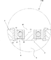
本実施形態においては、ベアリング手段4を用いることで、受け部材2が支持部材3に回動自在に支持されている。また、支持部材3は、周縁部31が下方に突出した構成となっており、これによって受け部材2が位置する箇所の下方側に空間5が形成されている。
1. First Embodiment First, an end pin holder according to a first embodiment will be described by way of example with reference to FIGS.
In the present embodiment, by using the bearing means 4, the receiving
[受け部材]
受け部材2は、エンドピンPの先端が突き当てられる突当ステージ21を備えている。そして、受け部材2は、ベアリング手段4(後述)などによって、支持部材3(後述)に回動自在に支持される。
[Receiving member]
The receiving
本実施形態においては、図3に例示するように、受け部材2がベアリング手段4の内輪42側に位置固定されている。具体的には、ベアリング手段4の軸孔40に嵌合するような形状の挿入部が受け部材2の下部に形成されており、この挿入部をベアリング手段4の軸孔40に挿入して固定することで、受け部材2をベアリング手段4の内輪42側に位置固定してある。ベアリング手段4の外輪41側は、後述するように、支持部材3に固定される。
In the present embodiment, as illustrated in FIG. 3, the
そして、受け部材2には、挿入部の上方に突当ステージ21が形成されている。本実施形態において、図2に例示するように、突当ステージ21は、平面視が円状であり、略平坦面である。突当ステージ21は、エンドピンホルダー1を床面Fに置いた状態で、床面Fと概ね平行な略平坦面となっている。
The
さらに、受け部材2は、突当ステージ21の外周に立上壁22を有している。本実施形態において、立上壁22は、突当ステージ21の外周に外側斜め上方に向けて立ち上がっている。
Further, the
ここで、図4に、受け部材2の変形例を示す。本変形例は、突当ステージ21が、ベアリング手段4の軸孔40の内側に位置するように構成されたものである。具体的には、受け部材2が、ベアリング手段4の軸孔40に嵌合するような平面形状の挿入部を備えており、この挿入部をベアリング手段4の軸孔40に挿入して固定することで、受け部材2をベアリング手段4の内輪42側に位置固定するように構成してある。図4に示す例では、受け部材2は、挿入部の下端にフランジ部を備えており、挿入部を軸孔40に下方から挿入してベアリング手段4の内輪42側に位置固定される。
Here, FIG. 4 shows a modification of the receiving
そして、受け部材2の上面(挿入部の上面)が突当ステージ21となっており、挿入部は、突当ステージ21がベアリング手段4の軸孔40の内側に位置するような長さ(高さ)となっている。ここでも、突当ステージ21は、エンドピンホルダー1を床面Fに置いた状態で、床面Fと概ね平行な略平坦面となっている。
The upper surface of the receiving member 2 (the upper surface of the insertion portion) is the
[支持部材]
支持部材3は、前述した受け部材2を回動自在に支持する。具体的には、支持部材3は、ベアリング手段4(後述)などによって、受け部材2を回動自在に支持する。
[Support member]
The
本実施形態においては、図3に例示するように、支持部材3の中央部に設けた貫通孔に保持具35を介してベアリング手段4が嵌め込まれることで、支持部材3にベアリング手段4の外輪41側が固定されている。図1又は図3に例示するように、ベアリング手段4は、横になった水平な状態(軸孔40が上下方向に開口した状態)で、支持部材3の中央部に位置している。
In the present embodiment, as illustrated in FIG. 3, the outer ring of the bearing means 4 is fitted to the
そして、本実施形態においては、受け部材2がベアリング手段4の軸穴40に位置固定されているため、受け部材2が支持部材3に対してスムーズに回動自在となる。すると、受け部材2が備える突当ステージ21(床面Fと概ね平行な略平坦面である)が水平面内において回動自在となる結果、チェロの演奏時に、主に水平方向の振動が床に伝播しにくくなるのである。
In this embodiment, since the receiving
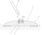
また、本実施形態において、支持部材3は、受け部材2が位置する箇所の下方側に空間5が形成されるように周縁部31が下方に突出した構成となっている。これにより、床面Fに設置した際に、受け部材2の部分が床面Fから浮いたような位置となる。支持部材3は、図1に例示するような偏平ドーム状(縦断面が略アーチ状)の構成とすることが好ましい。
Further, in the present embodiment, the
また、支持部材3の材質は、木、竹、プラスチックなどとすることができる。これらの材料は弾性が比較的高く支持部材に適度な弾性を付与しやすい。また、これらの材料をカーボン繊維などで補強してもよい。さらに、支持部材3の重量が軽くなるように、支持部材3には比重の小さい材料を用いることが好ましい。
The material of the
支持部材3の大きさは、特に制限されないが、50〜160mmが好ましい。また、支持部材3の厚み(天井部の厚み)は、材質にもよるが、適度な弾性と強度を両立させるために、2〜7mmであることが好ましい。
The size of the
さらに、支持部材3には、空間5と支持部材3の外面側とを連通する複数の貫通孔30が形成されている。貫通孔30の形状は、特に制限されないが、円径又は楕円形であることが好ましい。異なる大きさの貫通孔30を形成してもよい。
Further, the
また、貫通孔30の大きさ(最大部径)も、特に制限されないが、2mm以上であることが好ましい。貫通孔30の個数も、複数個であれば特に制限されないが、支持部材3の材料の堅さや厚みに応じて、適度な弾性を付与する観点から適宜の数を形成することができる。
Further, the size (maximum part diameter) of the through
さらに、複数個の貫通孔30を、受け部材2を中心とする概ね同一円周上に配置することや、図2などに例示するように、受け部材2を中心とする概ね同心円上に配置することもできる。
Further, the plurality of through
[ベアリング手段]
本実施形態では、前述したように、支持部材3に受け部材2を回動自在に支持するために、ベアリング手段4を用いている。ベアリング手段4としては、例えば、外輪41(アウターレース)と、内輪42(インナーレース)と、外輪41と内輪42の間に配置した複数個の転動体43と、を備えた、いわゆる転がり軸受を用いることができる。
[Bearing means]
In the present embodiment, as described above, the bearing means 4 is used to rotatably support the receiving
ベアリング手段4として、比較的小さくて軽いものを用いることが好ましい。ベアリング手段4の内径(軸孔40の径)は3〜10mmが好ましく、5〜8mmがより好ましい。 It is preferable to use a relatively small and light bearing means 4. The inner diameter of the bearing means 4 (the diameter of the shaft hole 40) is preferably 3 to 10 mm, and more preferably 5 to 8 mm.
[滑り止め部材]
滑り止め部材7は、エンドピンホルダー1を滑りにくくするものであり、床面Fと接する箇所に設けられる。図1の例では、支持部材3の周縁部31に滑り止め部材7が設けられている。
[Anti-slip member]
The
滑り止め部材7の材質は、滑り止め効果があれば特に制限されないが、天然ゴムや合成ゴム(例えば、シリコンゴムやウレタンゴム)等のゴム素材とすることが好ましい。
The material of the
2.第二実施形態
次に、図5を用いて、第二実施形態のエンドピンホルダーを例示説明する。
2. Second Embodiment Next, an end pin holder according to a second embodiment will be described with reference to FIG.
本実施形態のエンドピンホルダーは、第一実施形態のものとは支持部材3の構成が異なる。また、補強板6を備えている点でも第一実施形態のものとは異なる。
The end pin holder of this embodiment differs in the structure of the
具体的には、図5に示すように、本実施形態の支持部材3は、第一実施形態のものよりも材厚(天井部の厚み)が薄く、より偏平状である。また、貫通孔30の数も少ない。
Specifically, as shown in FIG. 5, the
また、本実施形態では、支持部材3を補強する補強板6が取り付けられている。補強板6は、支持部材3の周縁部31に取り付けられた板状体であり、支持部材3と概ね同じ外形形状で中央に孔部を有するドーナツ状の補強板6が、支持部材3の周縁部31に内嵌め状態で取り付けてある。
Moreover, in this embodiment, the
さらに、滑り止め部材7が、補強板6の下面と支持部材3の周縁部31を跨ぐように設けられている。
Further, the
3.第三実施形態
最後に、図6を用いて、第三実施形態のエンドピンホルダーを例示説明する。
3. Third Embodiment Finally, the end pin holder of the third embodiment will be described with reference to FIG.
本実施形態のエンドピンホルダーは、第一及び第二実施形態のものとは支持部材3の構成が異なる。具体的には、周縁部が下方に突出した構成となっておらず受け部材2が位置する箇所の下方側に空間が形成されていない。そして、支持部材3の中央部に開いた取り付け穴に保持具を介してベアリング手段4が嵌め込まれている。
The end pin holder of this embodiment differs in the structure of the supporting
4.エンドピンホルダーの使用方法
これらのエンドピンホルダー1は、例えば、床面Fに置いた状態で、チェロのエンドピンPの先端を突当ステージ21に突き当てて演奏することができる。
4). How to Use End Pin Holders These
本来、楽器の音色・響き・演奏性というものは極めて微妙でデリケートなものであるが、これらエンドピンホルダー1を用いてチェロを演奏すれば、自然な楽器の響きに近づけることで音響や音質を改善することができ、また奏者においてはチェロからの反応性(発音)も改善されることが期待されるのである。
Originally, the tone, reverberation, and performance of musical instruments are extremely delicate and delicate, but if you play a cello using these
以上、特定の実施形態を参照して本発明を説明したが、本発明は上記実施形態に限定されるものではなく、当該技術分野における熟練者等により、本出願の願書に添付された特許請求の範囲から逸脱することなく、種々の変更及び修正が可能である。 Although the present invention has been described above with reference to specific embodiments, the present invention is not limited to the above-described embodiments, and claims attached to the application of the present application by those skilled in the art or the like. Various changes and modifications can be made without departing from the scope.
1 エンドピンホルダー
2 受け部材
21 突当ステージ
22 立上壁
3 支持部材
30 貫通孔
31 周縁部
35 保持具
4 ベアリング手段
40 軸孔
41 外輪
42 内輪
43 転動体
5 空間
6 補強板
7 滑り止め部材
P エンドピン
F 床面
1 End pin holder
2 receiving member
21 Hit stage
22 Rising wall
3 Support members
30 Through hole
31 Edge
35 Holder
4 Bearing means
40 shaft hole
41 outer ring
42 inner ring
43 Rolling elements
5
P End pin F Floor
Claims (6)
この受け部材を支持する支持部材と、を備え、
前記受け部材は、ベアリング手段を介して前記支持部材に回動自在に支持されており、
前記支持部材は、前記受け部材が位置する箇所の下方側に空間が形成されるように周縁部が下方に突出した、偏平ドーム状の構成となっているとともに、前記空間と前記支持部材の外面側とを連通する複数の貫通孔が形成されている、
エンドピンホルダー。
A receiving member having an abutment stage against which the tip of the cello end pin is abutted;
A support member for supporting the receiving member,
The receiving member is rotatably supported by the support member via bearing means ,
The support member has a flat dome-like configuration in which a peripheral portion protrudes downward so that a space is formed below a position where the receiving member is located, and the outer surface of the space and the support member A plurality of through holes communicating with the side are formed ,
End pin holder.
ベアリング手段の内輪側に受け部材が位置固定されている、
請求項1に記載のエンドピンホルダー。
The bearing means is fixed to the support member on the outer ring side,
The receiving member is fixed to the inner ring side of the bearing means.
The end pin holder according to claim 1.
ベアリング手段の軸孔の内側に位置するように構成された、
請求項2に記載のエンドピンホルダー。
The rush stage
Configured to be located inside the shaft hole of the bearing means,
The end pin holder according to claim 2.
突当ステージの外周に立ち上がる立上壁を有する、
請求項1または2に記載のエンドピンホルダー。
The receiving member is
It has a rising wall that rises on the outer periphery of the abutment stage,
The end pin holder according to claim 1 or 2.
請求項1〜4のいずれか1項に記載のエンドピンホルダー。
The end pin holder according to any one of claims 1 to 4 , further comprising a reinforcing plate attached to a peripheral portion of the support member to reinforce the support member.
請求項1〜5のいずれか1項に記載のエンドピンホルダー。 The end pin holder according to any one of claims 1 to 5 , wherein an anti-slip member is provided at a location in contact with the floor surface.
Priority Applications (4)
| Application Number | Priority Date | Filing Date | Title |
|---|---|---|---|
| JP2015040021A JP6416017B2 (en) | 2015-03-02 | 2015-03-02 | End pin holder |
| EP15884001.7A EP3267436B1 (en) | 2015-03-02 | 2015-09-17 | Endpin holder |
| PCT/JP2015/076540 WO2016139835A1 (en) | 2015-03-02 | 2015-09-17 | Endpin holder |
| US15/554,862 US10013956B2 (en) | 2015-03-02 | 2015-09-17 | Endpin holder |
Applications Claiming Priority (1)
| Application Number | Priority Date | Filing Date | Title |
|---|---|---|---|
| JP2015040021A JP6416017B2 (en) | 2015-03-02 | 2015-03-02 | End pin holder |
Publications (3)
| Publication Number | Publication Date |
|---|---|
| JP2016161749A JP2016161749A (en) | 2016-09-05 |
| JP2016161749A5 JP2016161749A5 (en) | 2017-12-21 |
| JP6416017B2 true JP6416017B2 (en) | 2018-10-31 |
Family
ID=56845146
Family Applications (1)
| Application Number | Title | Priority Date | Filing Date |
|---|---|---|---|
| JP2015040021A Active JP6416017B2 (en) | 2015-03-02 | 2015-03-02 | End pin holder |
Country Status (4)
| Country | Link |
|---|---|
| US (1) | US10013956B2 (en) |
| EP (1) | EP3267436B1 (en) |
| JP (1) | JP6416017B2 (en) |
| WO (1) | WO2016139835A1 (en) |
Families Citing this family (4)
| Publication number | Priority date | Publication date | Assignee | Title |
|---|---|---|---|---|
| JP6416017B2 (en) * | 2015-03-02 | 2018-10-31 | 政己 相見 | End pin holder |
| CN110136673A (en) * | 2019-06-14 | 2019-08-16 | 吕云馨 | Musical instrument sound magnifier |
| TWI680452B (en) * | 2019-07-31 | 2019-12-21 | 王胤杰 | Struts for stringed instruments |
| JP7052784B2 (en) * | 2019-09-30 | 2022-04-12 | セイコーエプソン株式会社 | Optical devices, projectors, and methods of controlling optical devices |
Family Cites Families (27)
| Publication number | Priority date | Publication date | Assignee | Title |
|---|---|---|---|---|
| GB178336A (en) * | 1921-04-29 | 1922-04-20 | James Groves | An improved peg and support for violoncellos and the like |
| GB251989A (en) * | 1925-05-05 | 1926-09-30 | Pierre Lefevre | An improved rest or support |
| US2218142A (en) * | 1938-09-06 | 1940-10-15 | Walter R Becker | Accordion support |
| US2502229A (en) * | 1946-07-02 | 1950-03-28 | Miller James | Bass viol stand |
| US2814229A (en) * | 1956-01-18 | 1957-11-26 | Vaccaro Adelaide | Musical instrument support |
| US2974556A (en) * | 1958-01-30 | 1961-03-14 | Fawick Flexi Grip Co | End-rest foot-assembly for violoncellos, bass viols and the like |
| US3160050A (en) * | 1962-11-06 | 1964-12-08 | Klein Markus | End-rest assembly |
| US4018129A (en) * | 1974-11-26 | 1977-04-19 | Ralph Hollander | End-pin holder for string instruments |
| US4316402A (en) * | 1981-01-16 | 1982-02-23 | Richard Goldner | Adjustable end pin for the violoncello and the string bass |
| DE3935160A1 (en) * | 1989-02-01 | 1990-08-02 | Wilhelm Wolf | PARQUET PROTECTOR FOR STRING INSTRUMENTS |
| US5003858A (en) * | 1989-11-15 | 1991-04-02 | Rowell Frances E | Portable resonating platform and T-bar for securing the endpin and enhancing the tone of a cello |
| JPH0625891A (en) | 1992-02-24 | 1994-02-01 | Olin Corp | Method for improving discoloring resistance |
| JP2538044Y2 (en) * | 1992-09-07 | 1997-06-04 | 郁雄 秋山 | End pin stand |
| US5297771A (en) * | 1992-12-10 | 1994-03-29 | Mark Gilbert | Support assembly for standing musical instruments |
| JP2593205Y2 (en) * | 1993-08-26 | 1999-04-05 | 大三郎 澤居 | Acoustic vibration isolation type end pin receiver for musical instruments |
| DE19529482C1 (en) * | 1995-08-10 | 1997-02-13 | Reimund Korupp | Resonance box |
| JP3194186B2 (en) * | 1997-12-30 | 2001-07-30 | 泰永 上野 | Instrument or speaker support |
| US6696626B1 (en) * | 2002-06-19 | 2004-02-24 | Jon J. Pagenkopf | Cello endpin restraint |
| US7084337B1 (en) * | 2002-09-17 | 2006-08-01 | Thomas Hermann Schroeder | Ergonomic stringed instrument |
| US7342160B2 (en) * | 2004-04-23 | 2008-03-11 | Alberti John L | Adjustable support for a stringed musical instrument |
| JP3112322U (en) * | 2005-05-06 | 2005-08-11 | 朝計 福原 | 絃 Stabilizer for musical instruments |
| JP4793915B2 (en) * | 2005-11-15 | 2011-10-12 | 株式会社コスモジャパン | String instrument support |
| TWM290240U (en) * | 2005-11-21 | 2006-05-01 | Otto Musica Corp | Floor-type sounding apparatus of stringed instrument |
| JP3153830U (en) * | 2009-03-29 | 2009-09-24 | 士郎 林 | Stringed instrument performance aids |
| US8735702B1 (en) * | 2012-03-21 | 2014-05-27 | Deborah R. Miles | Portable dissipating medium used for removal of vibrational interference in a bowed string of a violin family instrument |
| JP6416017B2 (en) * | 2015-03-02 | 2018-10-31 | 政己 相見 | End pin holder |
| US9858903B2 (en) * | 2016-02-29 | 2018-01-02 | Thomas J DeVuono | Efficient acoustic enhancement of endpins and receptacles for stringed musical instruments and the like using customized filler materials |
-
2015
- 2015-03-02 JP JP2015040021A patent/JP6416017B2/en active Active
- 2015-09-17 EP EP15884001.7A patent/EP3267436B1/en active Active
- 2015-09-17 WO PCT/JP2015/076540 patent/WO2016139835A1/en active Application Filing
- 2015-09-17 US US15/554,862 patent/US10013956B2/en active Active
Also Published As
| Publication number | Publication date |
|---|---|
| EP3267436A1 (en) | 2018-01-10 |
| EP3267436B1 (en) | 2022-04-13 |
| EP3267436A4 (en) | 2018-10-03 |
| US10013956B2 (en) | 2018-07-03 |
| JP2016161749A (en) | 2016-09-05 |
| WO2016139835A1 (en) | 2016-09-09 |
| US20180047371A1 (en) | 2018-02-15 |
Similar Documents
| Publication | Publication Date | Title |
|---|---|---|
| JP6416017B2 (en) | End pin holder | |
| US7928303B2 (en) | Insert for cajon drum | |
| US8492632B1 (en) | Tuned bell harmonic musical instrument | |
| JP2007323075A (en) | Guitar body reinforcement | |
| US9691366B2 (en) | Hybrid drum apparatus | |
| CN105321508B (en) | Mounting structure and musical instrument for acoustic transducer | |
| JP2010072510A (en) | Cymbal set, sound-collecting device of cymbal and sound collection method of cymbal | |
| EP2795610B1 (en) | Percussion instrument | |
| JP3197284U (en) | End pin holder | |
| JP2007171682A (en) | Harp | |
| CN107025897B (en) | Three-dimensional curved surface structure of ancient organ panel | |
| US10163427B1 (en) | Percussion musical instrument | |
| CN106940994B (en) | Streamline type ancient organ abdominal cavity structure for optimizing tone quality | |
| US20180240441A1 (en) | String instrument | |
| KR200459882Y1 (en) | Gayageum Improved | |
| US20070234873A1 (en) | Drum Design with Acoustic Advantages and for minimal Travel from Drum to Drum | |
| US7842866B1 (en) | Musical instrument | |
| KR200415764Y1 (en) | Support for tradition stringed instrument | |
| KR200391693Y1 (en) | a Box shaped Percussion Instrument | |
| US9105258B2 (en) | Musical instrument | |
| KR200379608Y1 (en) | Gong support instrument | |
| CN202473196U (en) | BanHu drum | |
| JP3187041U (en) | Retrofit instrument for stringed instruments with sound hole | |
| US1883503A (en) | Stringed musical instrument | |
| KR200363432Y1 (en) | Xylophone's sound fixation a sphere |
Legal Events
| Date | Code | Title | Description |
|---|---|---|---|
| A521 | Request for written amendment filed |
Free format text: JAPANESE INTERMEDIATE CODE: A523 Effective date: 20171106 |
|
| A621 | Written request for application examination |
Free format text: JAPANESE INTERMEDIATE CODE: A621 Effective date: 20171106 |
|
| A131 | Notification of reasons for refusal |
Free format text: JAPANESE INTERMEDIATE CODE: A131 Effective date: 20180904 |
|
| A521 | Request for written amendment filed |
Free format text: JAPANESE INTERMEDIATE CODE: A523 Effective date: 20180912 |
|
| TRDD | Decision of grant or rejection written | ||
| A01 | Written decision to grant a patent or to grant a registration (utility model) |
Free format text: JAPANESE INTERMEDIATE CODE: A01 Effective date: 20181001 |
|
| A61 | First payment of annual fees (during grant procedure) |
Free format text: JAPANESE INTERMEDIATE CODE: A61 Effective date: 20181003 |
|
| R150 | Certificate of patent or registration of utility model |
Ref document number: 6416017 Country of ref document: JP Free format text: JAPANESE INTERMEDIATE CODE: R150 |
|
| R250 | Receipt of annual fees |
Free format text: JAPANESE INTERMEDIATE CODE: R250 |
|
| S111 | Request for change of ownership or part of ownership |
Free format text: JAPANESE INTERMEDIATE CODE: R313113 |
|
| R350 | Written notification of registration of transfer |
Free format text: JAPANESE INTERMEDIATE CODE: R350 |
|
| R250 | Receipt of annual fees |
Free format text: JAPANESE INTERMEDIATE CODE: R250 |