WO2016139835A1 - Endpin holder - Google Patents
Endpin holder Download PDFInfo
- Publication number
- WO2016139835A1 WO2016139835A1 PCT/JP2015/076540 JP2015076540W WO2016139835A1 WO 2016139835 A1 WO2016139835 A1 WO 2016139835A1 JP 2015076540 W JP2015076540 W JP 2015076540W WO 2016139835 A1 WO2016139835 A1 WO 2016139835A1
- Authority
- WO
- WIPO (PCT)
- Prior art keywords
- end pin
- support member
- receiving member
- pin holder
- cello
- Prior art date
Links
Images


Classifications
-
- G—PHYSICS
- G10—MUSICAL INSTRUMENTS; ACOUSTICS
- G10D—STRINGED MUSICAL INSTRUMENTS; WIND MUSICAL INSTRUMENTS; ACCORDIONS OR CONCERTINAS; PERCUSSION MUSICAL INSTRUMENTS; AEOLIAN HARPS; SINGING-FLAME MUSICAL INSTRUMENTS; MUSICAL INSTRUMENTS NOT OTHERWISE PROVIDED FOR
- G10D3/00—Details of, or accessories for, stringed musical instruments, e.g. slide-bars
- G10D3/01—Endpins or accessories therefor
-
- G—PHYSICS
- G10—MUSICAL INSTRUMENTS; ACOUSTICS
- G10G—REPRESENTATION OF MUSIC; RECORDING MUSIC IN NOTATION FORM; ACCESSORIES FOR MUSIC OR MUSICAL INSTRUMENTS NOT OTHERWISE PROVIDED FOR, e.g. SUPPORTS
- G10G5/00—Supports for musical instruments
-
- G—PHYSICS
- G10—MUSICAL INSTRUMENTS; ACOUSTICS
- G10G—REPRESENTATION OF MUSIC; RECORDING MUSIC IN NOTATION FORM; ACCESSORIES FOR MUSIC OR MUSICAL INSTRUMENTS NOT OTHERWISE PROVIDED FOR, e.g. SUPPORTS
- G10G5/00—Supports for musical instruments
- G10G5/005—Supports for musical instruments while playing, e.g. cord, strap or harness
-
- G—PHYSICS
- G10—MUSICAL INSTRUMENTS; ACOUSTICS
- G10D—STRINGED MUSICAL INSTRUMENTS; WIND MUSICAL INSTRUMENTS; ACCORDIONS OR CONCERTINAS; PERCUSSION MUSICAL INSTRUMENTS; AEOLIAN HARPS; SINGING-FLAME MUSICAL INSTRUMENTS; MUSICAL INSTRUMENTS NOT OTHERWISE PROVIDED FOR
- G10D1/00—General design of stringed musical instruments
- G10D1/02—Bowed or rubbed string instruments, e.g. violins or hurdy-gurdies
Definitions
- the present invention relates to an end pin holder, and specifically to an end pin holder against which a tip of an end pin of a cello is abutted.
- the tip of the end pin is abutted and fixed to an end pin holder (also called an end pin stopper) placed on the floor so that the position of the end pin is fixed with respect to the floor.
- an end pin holder also called an end pin stopper
- Such a conventional end pin holder has a structure that presupposes that the tip of the end pin is firmly held at a fixed position and the vibration of the stringed instrument is propagated to the floor surface.
- Patent Document 1 Utility Model Registration No. 3153830.
- the original cello (called baroque cello), when the violin genus was developed, had no end pins and was played with the cello body sandwiched between both legs. In this case, since the cello body is played in a state where it floats in the air, it is easy to ensure natural resonance vibration of the cello.
- An object of the present invention is to solve the problems of these conventional end pin holders, and to provide an end pin holder capable of bringing the sound and sound quality close to those of natural instruments when playing a cello having end pins. There is.
- an end pin holder includes a receiving member provided with an abutment stage against which a tip of an end pin of a cello is abutted, and a support member that supports the receiving member, The receiving member is configured to be rotatably supported by the support member.
- the vibration of the cello having the end pin (mainly the vibration in the rotating direction of the receiving member) propagates to the floor. Can be suppressed. Further, the cello having the end pin can be held while allowing free vibration. As a result, when playing a cello having an end pin, the sound and sound quality can be brought close to the sound of a natural musical instrument.
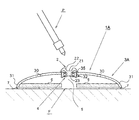
- FIG. 1 is a cross-sectional view of an end pin holder according to a first embodiment of the present invention
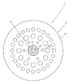
- FIG. 2 is a plan view of the end pin holder according to the first embodiment of the present invention
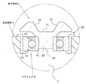
- 3 is a partially enlarged sectional view of FIG.
- FIG. 4 is a cross-sectional view showing a modification of the receiving member
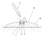
- FIG. 5 is a cross-sectional view of an end pin holder according to a second embodiment of the present invention
- FIG. 6 is a cross-sectional view of an end pin holder according to the third embodiment of the present invention.
- An end pin holder includes a receiving member provided with an abutment stage against which a tip portion of an end pin of a cello is abutted, and a supporting member that supports the receiving member, and the receiving member is the supporting member It is comprised so that it may be rotatably supported by.
- the receiving member is rotatably supported by the support member, it is possible to prevent the vibration of the cello having the end pin from propagating to the floor. Further, the cello having the end pin can be held while allowing free vibration. As a result, when playing a cello having an end pin, the sound and sound quality can be brought close to the sound of a natural musical instrument.
- the receiving member may be rotatably supported by the support member via a bearing, for example. According to this configuration, the contact stage of the receiving member can be smoothly rotated by the action of the bearing, and the vibration of the cello having the end pin can be prevented from propagating to the floor.
- the bearing may have an outer ring portion and an inner ring portion, for example, and the outer ring portion may be fixed to the support member and the inner ring portion fixed to the receiving member.
- the abutment stage may be configured to be positioned in, for example, a shaft hole surrounded by the inner ring portion of the bearing.
- the receiving member is configured to have a rising wall that rises upward at the outer peripheral portion of the abutting stage. According to this configuration, it is possible to prevent the end pin from being unintentionally detached from the abutting stage.
- the support member is configured so that the peripheral edge protrudes downward so that a space is formed below the receiving member.
- the receiving member when the end pin holder is installed on the floor surface, the receiving member is in a state of being floated from the floor surface, so that the vibration of the cello having the end pin can be further suppressed from propagating to the floor.
- the support member can be elastically deformed using the space, and the cello having the end pin can be elastically supported. As a result, it is possible to further suppress the vibration of the cello having the end pin from propagating to the floor.
- the support member is formed in a flat dome shape with a peripheral edge protruding downward so that a space is formed below the receiving member, and the support member has a plurality of spaces communicating with the outer surface side of the support member.
- a through hole may be formed.
- the support member can be more easily elastically deformed by forming a plurality of through holes in the support member. As a result, it is possible to further suppress the vibration of the cello having the end pin from propagating to the floor. Further, since the support member has a flat dome shape, it is easy to give the support member both elasticity and strength.
- the end pin holder according to the present invention may further include a reinforcing plate that is attached to the peripheral portion of the supporting member and reinforces the supporting member.
- end pin holder may further include an anti-slip member at a location in contact with the floor surface.
- An end pin holder according to each of the following embodiments includes a receiving member and a supporting member, and has a basic configuration in which the receiving member is rotatably supported by the supporting member.
- FIG.1, 5,6 in addition to an end pin holder, the end pin and the floor surface are also illustrated for convenience of explanation.
- the hatching of the cross section of the bearing is omitted.
- the end pin holder 1 is configured such that the receiving member 2 is rotatably supported by the support member 3 via the bearing 4.
- the support member 3 has a configuration in which the peripheral edge 31 protrudes downward. Thereby, a space 5 is formed below the receiving member 2.
- the receiving member 2 includes an abutment stage 21 against which the tip of the end pin P is abutted.
- the receiving member 2 is rotatably supported by the support member 3 by a bearing 4.
- the receiving member 2 is fixed to the inner ring portion 42 of the bearing 4 as shown in FIG. Specifically, an insertion portion 23 that fits into the shaft hole 40 surrounded by the inner ring portion 42 of the bearing 4 is formed in the lower portion of the receiving member 2.
- the receiving member 2 is fixed to the inner ring portion 42 of the bearing 4 by the insertion portion 23 being inserted and fitted into the shaft hole 40 of the bearing 4.
- the outer ring portion 41 of the bearing 4 is fixed to the support member 3 via the holder 35.
- the abutment stage 21 is formed above the insertion portion 23 of the receiving member 2.
- the abutment stage 21 is formed in a circular shape in plan view as shown in FIG.
- the abutment stage 21 is formed to have a flat surface parallel to the floor surface F or a substantially flat surface substantially parallel to the floor surface F in a state where the end pin holder 1 is placed on the floor surface F.
- the receiving member 2 has a rising wall 22 on the outer peripheral portion of the abutting stage 21.
- the rising wall 22 is formed on the outer peripheral portion of the abutment stage 21 so as to rise obliquely outward and upward.
- the receiving member 2 may be configured such that the abutment stage 21 is positioned in the shaft hole 40 of the bearing 4 as shown in FIG. Specifically, the receiving member 2 includes a substantially columnar insertion portion 24 that fits into the shaft hole 40 of the bearing 4, and the insertion portion 24 is inserted into the shaft hole 40 of the bearing 4 to fit.
- the inner ring portion 42 of the bearing 4 may be fixed.
- the receiving member 2 includes a flange portion 24a at the lower end portion of the insertion portion 24, and the insertion portion 24 has a shaft hole 40 so that the flange portion 24a contacts the lower end portion of the inner ring portion 42. It is fixed to the inner ring part 42 of the bearing 4 by being inserted from below.
- the upper surface of the receiving member 2 (the upper surface of the insertion portion 24) is the abutment stage 21.
- the insertion portion 24 has such a length (height) that the abutment stage 21 is positioned in the shaft hole 40 of the bearing 4.
- the abutment stage 21 is formed to have a flat surface parallel to the floor surface F or a substantially flat surface substantially parallel to the floor surface F in a state where the end pin holder 1 is placed on the floor surface F.
- the support member 3 is configured to rotatably support the receiving member 2 described above. More specifically, the support member 3 is configured to rotatably support the receiving member 2 via the bearing 4.
- the outer ring of the bearing 4 is fitted to the support member 3 by fitting the bearing 4 into the holding hole 32 provided in the central portion of the support member 3 via the holder 35.
- the part 41 is fixed.
- the bearing 4 is located in the center of the support member 3 in a horizontal state (a state where the shaft hole 40 is opened in the vertical direction).
- the receiving member 2 since the receiving member 2 is fixed in the shaft hole 40 of the bearing 4, the receiving member 2 can smoothly rotate with respect to the support member 3. As a result, the abutment stage 21 provided in the receiving member 2 is rotatable in a horizontal plane fixed to the inner ring portion 42 of the bearing 4. As a result, it is possible to suppress the horizontal vibration from propagating to the floor when the cello having the end pin P is played.
- the support member 3 has a configuration in which the peripheral edge portion 31 protrudes downward so that the space 5 is formed below the location where the receiving member 2 is located. Thereby, when the end pin holder 1 is installed on the floor surface F, the receiving member 2 is in a state of floating from the floor surface F, so that the vibration of the cello having the end pin P is further suppressed from propagating to the floor. Can do.
- the support member 3 preferably has a flat dome shape (vertical cross section is substantially arched) as shown in FIG.
- the material of the support member 3 it is preferable to use a material having relatively high elasticity such as wood, bamboo, or plastic. Thereby, moderate elasticity can be imparted to the support member 3.
- the support member 3 may be reinforced with carbon fiber or the like.
- a material of the support member 3 it is preferable to use a material having a small specific gravity so that the weight is reduced.
- the size of the support member 3 is, for example, 50 to 160 mm. Further, although the thickness of the support member 3 (thickness of the ceiling portion) depends on the material, it is preferably 2 to 7 mm in order to achieve both appropriate elasticity and strength.
- the support member 3 is formed with a plurality of through holes 30 that communicate the space 5 with the outer surface side of the support member 3.
- the shape of the through hole 30 is, for example, a circle or an ellipse.
- the size of each through hole 30 may be different from each other.
- the size (maximum diameter) of the through hole 30 is, for example, 2 mm or more.
- the number of the through holes 30 may be plural, and may be an appropriate number from the viewpoint of imparting appropriate elasticity according to the hardness and thickness of the material of the support member 3.
- the plurality of through holes 30 may be arranged on substantially the same circumference around the receiving member 2. Moreover, you may arrange
- the bearing 4 is used to rotatably support the receiving member 2 on the support member 3.
- the bearing 4 for example, as shown in FIG. 3, an outer ring portion 41 (outer race), an inner ring portion 42 (inner race), and a plurality of rolling elements disposed between the outer ring portion 41 and the inner ring portion 42. 43, so-called rolling bearings can be used.
- the inner diameter of the bearing 4 (the diameter of the shaft hole 40) is preferably 3 to 10 mm, and more preferably 5 to 8 mm.
- the anti-slip member 7 makes the end pin holder 1 difficult to slip, and is provided at a location in contact with the floor surface F.
- the anti-slip member 7 is provided on the peripheral edge 31 of the support member 3.
- the material of the anti-slip member 7 may be any material as long as it has an anti-slip effect, and may be a rubber material such as natural rubber or synthetic rubber (for example, silicon rubber or urethane rubber).
- the end pin holder 1 since the receiving member 2 is rotatably supported by the support member 3, it is possible to suppress the vibration of the cello having the end pin P from propagating to the floor. . Further, the cello having the end pin P can be held while allowing free vibration. As a result, when playing the cello having the end pin P, the sound and sound quality can be brought close to the sound of a natural musical instrument.
- the end pin holder 1A according to the second embodiment is different from the end pin holder 1 according to the first embodiment in that it includes a support member 3A instead of the support member 3 and further includes a reinforcing plate 6. is there.
- the support member 3A is thinner than the support member 3 (the thickness of the ceiling), and is formed in a flat dome shape.
- a holding hole 32 that rotatably holds the receiving member 2 via a holder 35 and a bearing 4 is formed in the central portion of the support member 3A. Further, the number of through holes 30 provided in the support member 3 ⁇ / b> A is smaller than the number of through holes 30 provided in the support member 3.
- the reinforcing plate 6 reinforces the supporting member 3 ⁇ / b> A and is attached to the peripheral edge 31 of the supporting member 3.
- the reinforcing plate 6 is a plate-shaped member having a ring shape, and is attached so as to be fitted inside the peripheral edge portion 31 of the support member 3.
- the anti-slip member 7 is provided so as to straddle the lower surface of the reinforcing plate 6 and the peripheral edge 31 of the support member 3.
- the end pin holder 1A since the receiving member 2 is rotatably supported by the support member 3B, similarly to the end pin holder 1 according to the first embodiment, the end pin holder 1A is provided.
- the cello vibration can be prevented from propagating to the floor. Further, the cello having the end pin P can be held while allowing free vibration. As a result, when playing the cello having the end pin P, the sound and sound quality can be brought close to the sound of a natural musical instrument.
- the support member 3A since the support member 3A is formed in a flat dome shape with the peripheral edge protruding downward, the support member 3A has both elasticity and strength. It becomes easy. Thus, even if the number of through holes 30 provided in the support member 3A is smaller than the number of through holes 30 provided in the support member 3, the support member 3A can have elasticity equivalent to that of the support member 3. it can.
- the end pin holder 1B according to the third embodiment is different from the end pin holder 1 according to the first embodiment in that a support member 3B is provided instead of the support member 3.
- the support member 3B has a solid structure with a flat dome shape.
- a concave portion 33 is formed in the central portion of the upper surface of the support member 3B so as to accommodate the receiving member 2 via the holder 35 and the bearing 4 in a rotatable manner.
- the end pin holder 1B similarly to the end pin holder 1 according to the first embodiment, since the receiving member 2 is rotatably supported by the support member 3B, the end pin holder 1B has the end pin P.
- the cello vibration can be prevented from propagating to the floor. Further, the cello having the end pin P can be held while allowing free vibration. As a result, when playing the cello having the end pin P, the sound and sound quality can be brought close to the sound of a natural musical instrument.
- end pin holders 1, 1 ⁇ / b> A, 1 ⁇ / b> B are used, for example, by being placed so that the tip of the end pin P included in the cello abuts against the abutment stage 21 in a state of being placed on the floor surface F.
- the end pin holder according to the present invention can bring the sound and sound quality close to the sound of a natural musical instrument when playing a cello having an end pin, and thus is also useful for a stringed instrument having an end pin such as a contrabass.
Landscapes
- Physics & Mathematics (AREA)
- Engineering & Computer Science (AREA)
- Acoustics & Sound (AREA)
- Multimedia (AREA)
- Auxiliary Devices For Music (AREA)
- Stringed Musical Instruments (AREA)
Abstract
An endpin holder (1) according to the present invention comprises a receiving member (2) provided with an abutting stage (21) that the tip of an endpin (P) of a cello abuts with and a support member (3) that supports the receiving member (2), wherein the receiving member (2) is rotatably supported by the support member (3). The receiving member (2) is rotatably supported by the support member (3) via a bearing (4). This configuration allows sound to approach the acoustics and tone of a natural instrument when a cello that has an endpin is played.
Description
本発明は、エンドピンホルダーに関し、具体的には、チェロが有するエンドピンの先端部が突き当てられるエンドピンホルダーに関する。
The present invention relates to an end pin holder, and specifically to an end pin holder against which a tip of an end pin of a cello is abutted.
従来、チェロやコントラバス等のエンドピンを有する弦楽器を演奏する際、エンドピンの先端部を直接床面に突き当てて固定することが行われている。しかしながら、床面の材質が硬い場合、エンドピンが滑って弦楽器を固定することができない。逆に、床面の材質が柔らかい場合、エンドピンを突き当てた箇所が窪んだり、傷付いたりすることが起こり得る。
Conventionally, when playing a stringed instrument having an end pin such as a cello or a contrabass, the end of the end pin is directly abutted against the floor surface and fixed. However, if the floor material is hard, the end pin cannot slide and the stringed instrument cannot be fixed. On the contrary, when the floor surface material is soft, the portion where the end pin is abutted may be depressed or damaged.
このため、一般的には、エンドピンが床面に対して位置を固定されるように、床面に置いたエンドピンホルダー(エンドピンストッパーとも称される)にエンドピンの先端部を突き当てて固定するようにしている。このような従来のエンドピンホルダーは、エンドピンの先端部を固定位置にしっかりと保持し、弦楽器の振動を床面に伝播させることを前提とした構造となっている。このようなエンドピンホルダーとしては、例えば、特許文献1(実用新案登録第3153830号公報)に記載されたものがある。
For this reason, in general, the tip of the end pin is abutted and fixed to an end pin holder (also called an end pin stopper) placed on the floor so that the position of the end pin is fixed with respect to the floor. I have to. Such a conventional end pin holder has a structure that presupposes that the tip of the end pin is firmly held at a fixed position and the vibration of the stringed instrument is propagated to the floor surface. An example of such an end pin holder is described in Patent Document 1 (Utility Model Registration No. 3153830).
バイオリン属の弦楽器が開発された当初のチェロ(バロックチェロと呼ばれる)は、エンドピンを備えていなかったため、チェロの胴体を両脚の間に挟んで演奏されていた。この場合、チェロの胴体が空中に浮かんだような状態で演奏されるため、チェロの自然な共鳴振動が確保されやすい。
The original cello (called baroque cello), when the violin genus was developed, had no end pins and was played with the cello body sandwiched between both legs. In this case, since the cello body is played in a state where it floats in the air, it is easy to ensure natural resonance vibration of the cello.
しかしながら、エンドピンの先端部を直接床面に突き当てて固定したり、従来のエンドピンホルダーを用いてエンドピンの先端部を固定したりする場合、演奏時の楽器の振動が床に伝播して床も振動(床鳴り)することになる。また、チェロの胴体の下部に固定されたエンドピンの下端部が床面又はエンドピンホルダーの1点で固定されるために、演奏中の楽器の胴体の自然な共鳴振動が抑制されることになる。これらの場合、エンドピンを有するチェロを演奏する際に、音響や音質が自然な楽器の響きから遠ざかることになる。
However, when the end of the end pin is directly abutted against the floor surface, or when the end of the end pin is fixed using a conventional end pin holder, the vibration of the musical instrument during the performance propagates to the floor and the floor also It will vibrate (flooding). Further, since the lower end portion of the end pin fixed to the lower part of the cello body is fixed at one point of the floor surface or the end pin holder, natural resonance vibration of the body of the musical instrument being played is suppressed. In these cases, when playing a cello having an end pin, the sound and sound quality are kept away from the sound of a natural musical instrument.
本発明の目的は、これら従来のエンドピンホルダーの課題を解決することにあって、エンドピンを有するチェロを演奏する際に、音響や音質を自然な楽器の響きに近づけることのできるエンドピンホルダーを提供することにある。
An object of the present invention is to solve the problems of these conventional end pin holders, and to provide an end pin holder capable of bringing the sound and sound quality close to those of natural instruments when playing a cello having end pins. There is.
前記課題を解決するために、本発明に係るエンドピンホルダーは、チェロが有するエンドピンの先端部が突き当てられる突当ステージを備えた受け部材と、前記受け部材を支持する支持部材と、を備え、前記受け部材は、前記支持部材に回動自在に支持されるように構成されている。
In order to solve the above-mentioned problem, an end pin holder according to the present invention includes a receiving member provided with an abutment stage against which a tip of an end pin of a cello is abutted, and a support member that supports the receiving member, The receiving member is configured to be rotatably supported by the support member.
本発明に係るエンドピンホルダーによれば、受け部材が支持部材に回動自在に支持されているので、エンドピンを有するチェロの振動(主に受け部材の回動方向の振動)が床に伝播することを抑えることができる。また、エンドピンを有するチェロの自由な振動を許しながら保持することができる。その結果、エンドピンを有するチェロを演奏する際に、音響や音質を自然な楽器の響きに近づけることができる。
According to the end pin holder of the present invention, since the receiving member is rotatably supported by the support member, the vibration of the cello having the end pin (mainly the vibration in the rotating direction of the receiving member) propagates to the floor. Can be suppressed. Further, the cello having the end pin can be held while allowing free vibration. As a result, when playing a cello having an end pin, the sound and sound quality can be brought close to the sound of a natural musical instrument.
本発明のこれらと他の目的と特徴は、添付された図面についての好ましい実施形態に関連した次の記述から明らかになる。この図面においては、
図1は、本発明の第一実施形態に係るエンドピンホルダーの断面図であり、
図2は、本発明の第一実施形態に係るエンドピンホルダーの平面図であり、
図3は、図1の一部拡大断面図であり、
図4は、受け部材の変形例を示す断面図であり、
図5は、本発明の第二実施形態に係るエンドピンホルダーの断面図であり、
図6は、本発明の第三実施形態に係るエンドピンホルダーの断面図である。
These and other objects and features of the invention will become apparent from the following description taken in conjunction with the preferred embodiments with reference to the accompanying drawings. In this drawing,
FIG. 1 is a cross-sectional view of an end pin holder according to a first embodiment of the present invention, FIG. 2 is a plan view of the end pin holder according to the first embodiment of the present invention, 3 is a partially enlarged sectional view of FIG. FIG. 4 is a cross-sectional view showing a modification of the receiving member, FIG. 5 is a cross-sectional view of an end pin holder according to a second embodiment of the present invention, FIG. 6 is a cross-sectional view of an end pin holder according to the third embodiment of the present invention.
本発明に係るエンドピンホルダーは、チェロが有するエンドピンの先端部が突き当てられる突当ステージを備えた受け部材と、前記受け部材を支持する支持部材と、を備え、前記受け部材は、前記支持部材に回動自在に支持されるように構成されている。
An end pin holder according to the present invention includes a receiving member provided with an abutment stage against which a tip portion of an end pin of a cello is abutted, and a supporting member that supports the receiving member, and the receiving member is the supporting member It is comprised so that it may be rotatably supported by.
この構成によれば、受け部材が支持部材に回動自在に支持されているので、エンドピンを有するチェロの振動が床に伝播することを抑えることができる。また、エンドピンを有するチェロの自由な振動を許しながら保持することができる。その結果、エンドピンを有するチェロを演奏する際に、音響や音質を自然な楽器の響きに近づけることができる。
According to this configuration, since the receiving member is rotatably supported by the support member, it is possible to prevent the vibration of the cello having the end pin from propagating to the floor. Further, the cello having the end pin can be held while allowing free vibration. As a result, when playing a cello having an end pin, the sound and sound quality can be brought close to the sound of a natural musical instrument.
なお、受け部材は、例えば、ベアリングを介して支持部材に回動自在に支持されてもよい。この構成によれば、ベアリングの作用により、受け部材の突当ステージがスムーズに回動することができ、エンドピンを有するチェロの振動が床に伝播することを抑えることができる。
Note that the receiving member may be rotatably supported by the support member via a bearing, for example. According to this configuration, the contact stage of the receiving member can be smoothly rotated by the action of the bearing, and the vibration of the cello having the end pin can be prevented from propagating to the floor.
なお、ベアリングは、例えば、外輪部と、内輪部とを有し、外輪部が支持部材に固定され、内輪部が受け部材に固定されるように構成すればよい。
The bearing may have an outer ring portion and an inner ring portion, for example, and the outer ring portion may be fixed to the support member and the inner ring portion fixed to the receiving member.
また、突当ステージは、例えば、ベアリングの内輪部に囲まれた軸孔内に位置するように構成すればよい。
Further, the abutment stage may be configured to be positioned in, for example, a shaft hole surrounded by the inner ring portion of the bearing.
また、受け部材は、突当ステージの外周部に、上方へ立ち上がる立上壁を有するように構成されることが好ましい。この構成によれば、エンドピンが突当ステージ上から意図せず外れることを抑えることができる。
Further, it is preferable that the receiving member is configured to have a rising wall that rises upward at the outer peripheral portion of the abutting stage. According to this configuration, it is possible to prevent the end pin from being unintentionally detached from the abutting stage.
また、支持部材は、受け部材の下方に空間が形成されるように、周縁部が下方に突出するように構成されることが好ましい。この構成によれば、エンドピンホルダーを床面に設置した際、受け部材が床面から浮いたような状態となるので、エンドピンを有するチェロの振動が床に伝播することをより一層抑えることができる。また、この構成によれば、支持部材が前記空間を利用して弾性変形することが可能になり、エンドピンを有するチェロを弾性的に支持することができる。その結果、エンドピンを有するチェロの振動が床に伝播することをより一層抑えることができる。
Further, it is preferable that the support member is configured so that the peripheral edge protrudes downward so that a space is formed below the receiving member. According to this configuration, when the end pin holder is installed on the floor surface, the receiving member is in a state of being floated from the floor surface, so that the vibration of the cello having the end pin can be further suppressed from propagating to the floor. . Further, according to this configuration, the support member can be elastically deformed using the space, and the cello having the end pin can be elastically supported. As a result, it is possible to further suppress the vibration of the cello having the end pin from propagating to the floor.
また、支持部材は、受け部材の下方に空間が形成されるように、周縁部が下方に突出する偏平ドーム状に形成され、支持部材には空間と支持部材の外面側とを連通する複数の貫通孔が形成されてもよい。この構成によれば、支持部材に複数の貫通孔を形成することにより、支持部材が一層弾性変形しやすくすることができる。その結果、エンドピンを有するチェロの振動が床に伝播することをより一層抑えることができる。また、支持部材が偏平ドーム状の形状を有することにより、支持部材に弾性と強度の両方を持たせることが容易になる。
Further, the support member is formed in a flat dome shape with a peripheral edge protruding downward so that a space is formed below the receiving member, and the support member has a plurality of spaces communicating with the outer surface side of the support member. A through hole may be formed. According to this configuration, the support member can be more easily elastically deformed by forming a plurality of through holes in the support member. As a result, it is possible to further suppress the vibration of the cello having the end pin from propagating to the floor. Further, since the support member has a flat dome shape, it is easy to give the support member both elasticity and strength.
また、本発明に係るエンドピンホルダーは、更に、支持部材の周縁部に取り付けられて支持部材を補強する補強板を備えてもよい。
The end pin holder according to the present invention may further include a reinforcing plate that is attached to the peripheral portion of the supporting member and reinforces the supporting member.
また、本発明に係るエンドピンホルダーは、更に、床面と接する箇所に滑り止め部材を備えてもよい。
Further, the end pin holder according to the present invention may further include an anti-slip member at a location in contact with the floor surface.
以下、本発明の実施形態に係るエンドピンホルダーについて説明する。以下の各実施形態に係るエンドピンホルダーは、受け部材と支持部材とを備え、受け部材が支持部材に回動自在に支持されるという基本構成を備えている。
Hereinafter, the end pin holder according to the embodiment of the present invention will be described. An end pin holder according to each of the following embodiments includes a receiving member and a supporting member, and has a basic configuration in which the receiving member is rotatably supported by the supporting member.
以下の各実施形態はあくまで本発明を例示説明するものであって、本発明は、以下の具体的な各実施形態に限定されるものではない。
The following embodiments are merely illustrative of the present invention, and the present invention is not limited to the following specific embodiments.
なお、図1、5、6については、説明の便宜上、エンドピンホルダーに加えて、エンドピン及び床面も図示している。また、ベアリングの断面部分のハッチングは省略している。
In addition, about FIG.1, 5,6, in addition to an end pin holder, the end pin and the floor surface are also illustrated for convenience of explanation. In addition, the hatching of the cross section of the bearing is omitted.
(第一実施形態)
図1~図3を用いて、本発明の第一実施形態に係るエンドピンホルダー1について説明する。 (First embodiment)
Theend pin holder 1 according to the first embodiment of the present invention will be described with reference to FIGS.
図1~図3を用いて、本発明の第一実施形態に係るエンドピンホルダー1について説明する。 (First embodiment)
The
本第一実施形態に係るエンドピンホルダー1は、受け部材2がベアリング4を介して支持部材3に回動自在に支持されるように構成されている。また、支持部材3は、周縁部31が下方に突出した構成を有している。これにより、受け部材2の下方には、空間5が形成されている。
The end pin holder 1 according to the first embodiment is configured such that the receiving member 2 is rotatably supported by the support member 3 via the bearing 4. The support member 3 has a configuration in which the peripheral edge 31 protrudes downward. Thereby, a space 5 is formed below the receiving member 2.
[受け部材]
受け部材2は、エンドピンPの先端部が突き当てられる突当ステージ21を備えている。また、受け部材2は、ベアリング4によって、支持部材3に回動自在に支持されている。 [Receiving member]
The receivingmember 2 includes an abutment stage 21 against which the tip of the end pin P is abutted. The receiving member 2 is rotatably supported by the support member 3 by a bearing 4.
受け部材2は、エンドピンPの先端部が突き当てられる突当ステージ21を備えている。また、受け部材2は、ベアリング4によって、支持部材3に回動自在に支持されている。 [Receiving member]
The receiving
本第一実施形態において、受け部材2は、図3に示すように、ベアリング4の内輪部42に固定されている。具体的には、受け部材2の下部には、ベアリング4の内輪部42に囲まれた軸孔40に嵌合する挿入部23が形成されている。受け部材2は、挿入部23がベアリング4の軸孔40に挿入されて嵌合することで、ベアリング4の内輪部42に固定される。ベアリング4の外輪部41は、保持具35を介して支持部材3に固定される。
In the first embodiment, the receiving member 2 is fixed to the inner ring portion 42 of the bearing 4 as shown in FIG. Specifically, an insertion portion 23 that fits into the shaft hole 40 surrounded by the inner ring portion 42 of the bearing 4 is formed in the lower portion of the receiving member 2. The receiving member 2 is fixed to the inner ring portion 42 of the bearing 4 by the insertion portion 23 being inserted and fitted into the shaft hole 40 of the bearing 4. The outer ring portion 41 of the bearing 4 is fixed to the support member 3 via the holder 35.
突当ステージ21は、受け部材2の挿入部23の上方に形成されている。本第一実施形態において、突当ステージ21は、図2に示すように、平面視において円形に形成されている。また、突当ステージ21は、エンドピンホルダー1を床面Fに置いた状態において、床面Fと平行な平坦面又は概ね平行な略平坦面を有するように形成されている。
The abutment stage 21 is formed above the insertion portion 23 of the receiving member 2. In the first embodiment, the abutment stage 21 is formed in a circular shape in plan view as shown in FIG. The abutment stage 21 is formed to have a flat surface parallel to the floor surface F or a substantially flat surface substantially parallel to the floor surface F in a state where the end pin holder 1 is placed on the floor surface F.
また、受け部材2は、突当ステージ21の外周部に立上壁22を有している。本第一実施形態において、立上壁22は、突当ステージ21の外周部に外側斜め上方に向けて立ち上がるように形成されている。
Further, the receiving member 2 has a rising wall 22 on the outer peripheral portion of the abutting stage 21. In the first embodiment, the rising wall 22 is formed on the outer peripheral portion of the abutment stage 21 so as to rise obliquely outward and upward.
なお、受け部材2は、図4に示すように、突当ステージ21が、ベアリング4の軸孔40内に位置するように構成されてもよい。具体的には、受け部材2は、ベアリング4の軸孔40に嵌合する略円柱形の挿入部24を備え、当該挿入部24がベアリング4の軸孔40に挿入されて嵌合することで、ベアリング4の内輪部42に固定されてもよい。
The receiving member 2 may be configured such that the abutment stage 21 is positioned in the shaft hole 40 of the bearing 4 as shown in FIG. Specifically, the receiving member 2 includes a substantially columnar insertion portion 24 that fits into the shaft hole 40 of the bearing 4, and the insertion portion 24 is inserted into the shaft hole 40 of the bearing 4 to fit. The inner ring portion 42 of the bearing 4 may be fixed.
なお、図4に示す変形例において、受け部材2は、挿入部24の下端部にフランジ部24aを備え、フランジ部24aが内輪部42の下端部に接触するように挿入部24が軸孔40に下方から挿入されることで、ベアリング4の内輪部42に固定される。
4, the receiving member 2 includes a flange portion 24a at the lower end portion of the insertion portion 24, and the insertion portion 24 has a shaft hole 40 so that the flange portion 24a contacts the lower end portion of the inner ring portion 42. It is fixed to the inner ring part 42 of the bearing 4 by being inserted from below.
また、図4に示す変形例においては、受け部材2の上面(挿入部24の上面)が突当ステージ21となっている。挿入部24は、突当ステージ21がベアリング4の軸孔40内に位置するような長さ(高さ)を有している。また、突当ステージ21は、エンドピンホルダー1を床面Fに置いた状態において、床面Fと平行な平坦面又は概ね平行な略平坦面を有するように形成されている。
In the modification shown in FIG. 4, the upper surface of the receiving member 2 (the upper surface of the insertion portion 24) is the abutment stage 21. The insertion portion 24 has such a length (height) that the abutment stage 21 is positioned in the shaft hole 40 of the bearing 4. The abutment stage 21 is formed to have a flat surface parallel to the floor surface F or a substantially flat surface substantially parallel to the floor surface F in a state where the end pin holder 1 is placed on the floor surface F.
[支持部材]
支持部材3は、前述した受け部材2を回動自在に支持するように構成されている。より具体的には、支持部材3は、ベアリング4を介して、受け部材2を回動自在に支持するように構成されている。 [Support member]
Thesupport member 3 is configured to rotatably support the receiving member 2 described above. More specifically, the support member 3 is configured to rotatably support the receiving member 2 via the bearing 4.
支持部材3は、前述した受け部材2を回動自在に支持するように構成されている。より具体的には、支持部材3は、ベアリング4を介して、受け部材2を回動自在に支持するように構成されている。 [Support member]
The
本第一実施形態においては、図3に示すように、支持部材3の中央部に設けた保持穴32に保持具35を介してベアリング4が嵌め込まれることで、支持部材3にベアリング4の外輪部41が固定されている。図1に示すように、ベアリング4は、横になった水平な状態(軸孔40が上下方向に開口した状態)で、支持部材3の中央部に位置している。
In the first embodiment, as shown in FIG. 3, the outer ring of the bearing 4 is fitted to the support member 3 by fitting the bearing 4 into the holding hole 32 provided in the central portion of the support member 3 via the holder 35. The part 41 is fixed. As shown in FIG. 1, the bearing 4 is located in the center of the support member 3 in a horizontal state (a state where the shaft hole 40 is opened in the vertical direction).
本第一実施形態においては、受け部材2がベアリング4の軸孔40内に固定されているため、受け部材2が支持部材3に対してスムーズに回動することができる。これにより、受け部材2が備える突当ステージ21が、ベアリング4の内輪部42に固定される水平面内において回動自在となる。その結果、エンドピンPを有するチェロの演奏時に、水平方向の振動が床に伝播することを抑えることができる。
In the first embodiment, since the receiving member 2 is fixed in the shaft hole 40 of the bearing 4, the receiving member 2 can smoothly rotate with respect to the support member 3. As a result, the abutment stage 21 provided in the receiving member 2 is rotatable in a horizontal plane fixed to the inner ring portion 42 of the bearing 4. As a result, it is possible to suppress the horizontal vibration from propagating to the floor when the cello having the end pin P is played.
また、本第一実施形態において、支持部材3は、受け部材2が位置する箇所の下方側に空間5が形成されるように、周縁部31が下方に突出した構成を有している。これにより、エンドピンホルダー1を床面Fに設置した際、受け部材2が床面Fから浮いたような状態となるので、エンドピンPを有するチェロの振動が床に伝播することをより一層抑えることができる。支持部材3は、図1に示すような偏平ドーム状(縦断面が略アーチ状)の構成とすることが好ましい。
In the first embodiment, the support member 3 has a configuration in which the peripheral edge portion 31 protrudes downward so that the space 5 is formed below the location where the receiving member 2 is located. Thereby, when the end pin holder 1 is installed on the floor surface F, the receiving member 2 is in a state of floating from the floor surface F, so that the vibration of the cello having the end pin P is further suppressed from propagating to the floor. Can do. The support member 3 preferably has a flat dome shape (vertical cross section is substantially arched) as shown in FIG.
また、支持部材3の材質としては、例えば、木、竹、プラスチックなど比較的弾性が高い材料が用いられることが好ましい。これにより、支持部材3に適度な弾性を付与することができる。また、支持部材3は、カーボン繊維などで補強されてもよい。また、支持部材3の材質としては、重量が軽くなるように、比重の小さい材料が用いられることが好ましい。
In addition, as the material of the support member 3, it is preferable to use a material having relatively high elasticity such as wood, bamboo, or plastic. Thereby, moderate elasticity can be imparted to the support member 3. The support member 3 may be reinforced with carbon fiber or the like. Moreover, as a material of the support member 3, it is preferable to use a material having a small specific gravity so that the weight is reduced.
支持部材3の大きさは、例えば、50~160mmである。また、支持部材3の厚み(天井部の厚み)は、材質にもよるが、適度な弾性と強度を両立させるために、2~7mmであることが好ましい。
The size of the support member 3 is, for example, 50 to 160 mm. Further, although the thickness of the support member 3 (thickness of the ceiling portion) depends on the material, it is preferably 2 to 7 mm in order to achieve both appropriate elasticity and strength.
また、支持部材3には、空間5と支持部材3の外面側とを連通する複数の貫通孔30が形成されている。貫通孔30の形状は、例えば、円形又は楕円形である。各貫通孔30の大きさは、互いに異なっていてもよい。
Also, the support member 3 is formed with a plurality of through holes 30 that communicate the space 5 with the outer surface side of the support member 3. The shape of the through hole 30 is, for example, a circle or an ellipse. The size of each through hole 30 may be different from each other.
また、貫通孔30の大きさ(最大部径)は、例えば、2mm以上である。貫通孔30の個数は、複数個であればよく、支持部材3の材料の堅さや厚みに応じて、適度な弾性を付与する観点から適当な個数とすればよい。
Further, the size (maximum diameter) of the through hole 30 is, for example, 2 mm or more. The number of the through holes 30 may be plural, and may be an appropriate number from the viewpoint of imparting appropriate elasticity according to the hardness and thickness of the material of the support member 3.
また、複数個の貫通孔30は、受け部材2を中心とする概ね同一円周上に配置してもよい。また、複数の貫通孔30は、図2などに示すように、受け部材2を中心とする概ね同心円上に配置してもよい。
Further, the plurality of through holes 30 may be arranged on substantially the same circumference around the receiving member 2. Moreover, you may arrange | position the several through-hole 30 on the substantially concentric circle centering on the receiving member 2, as shown in FIG.
[ベアリング]
本第一実施形態においては、前述したように、支持部材3に受け部材2を回動自在に支持するために、ベアリング4を用いている。ベアリング4としては、例えば、図3に示すように、外輪部41(アウターレース)と、内輪部42(インナーレース)と、外輪部41と内輪部42の間に配置された複数個の転動体43とを備えた、いわゆる転がり軸受を用いることができる。 [bearing]
In the first embodiment, as described above, thebearing 4 is used to rotatably support the receiving member 2 on the support member 3. As the bearing 4, for example, as shown in FIG. 3, an outer ring portion 41 (outer race), an inner ring portion 42 (inner race), and a plurality of rolling elements disposed between the outer ring portion 41 and the inner ring portion 42. 43, so-called rolling bearings can be used.
本第一実施形態においては、前述したように、支持部材3に受け部材2を回動自在に支持するために、ベアリング4を用いている。ベアリング4としては、例えば、図3に示すように、外輪部41(アウターレース)と、内輪部42(インナーレース)と、外輪部41と内輪部42の間に配置された複数個の転動体43とを備えた、いわゆる転がり軸受を用いることができる。 [bearing]
In the first embodiment, as described above, the
ベアリング4としては、比較的小さくて軽いものを用いることが好ましい。ベアリング4の内径(軸孔40の径)は、3~10mmであることが好ましく、5~8mmであることがより好ましい。
It is preferable to use a relatively small and light bearing 4. The inner diameter of the bearing 4 (the diameter of the shaft hole 40) is preferably 3 to 10 mm, and more preferably 5 to 8 mm.
[滑り止め部材]
滑り止め部材7は、エンドピンホルダー1を滑りにくくするものであり、床面Fと接する箇所に設けられる。本第一実施形態においては、支持部材3の周縁部31に滑り止め部材7が設けられている。 [Anti-slip member]
Theanti-slip member 7 makes the end pin holder 1 difficult to slip, and is provided at a location in contact with the floor surface F. In the first embodiment, the anti-slip member 7 is provided on the peripheral edge 31 of the support member 3.
滑り止め部材7は、エンドピンホルダー1を滑りにくくするものであり、床面Fと接する箇所に設けられる。本第一実施形態においては、支持部材3の周縁部31に滑り止め部材7が設けられている。 [Anti-slip member]
The
滑り止め部材7の材質は、滑り止め効果を有するものであればよく、例えば、天然ゴムや合成ゴム(例えば、シリコンゴムやウレタンゴム)等のゴム素材であってもよい。
The material of the anti-slip member 7 may be any material as long as it has an anti-slip effect, and may be a rubber material such as natural rubber or synthetic rubber (for example, silicon rubber or urethane rubber).
本第一実施形態に係るエンドピンホルダー1によれば、受け部材2が支持部材3に回動自在に支持されているので、エンドピンPを有するチェロの振動が床に伝播することを抑えることができる。また、エンドピンPを有するチェロの自由な振動を許しながら保持することができる。その結果、エンドピンPを有するチェロを演奏する際に、音響や音質を自然な楽器の響きに近づけることができる。
According to the end pin holder 1 according to the first embodiment, since the receiving member 2 is rotatably supported by the support member 3, it is possible to suppress the vibration of the cello having the end pin P from propagating to the floor. . Further, the cello having the end pin P can be held while allowing free vibration. As a result, when playing the cello having the end pin P, the sound and sound quality can be brought close to the sound of a natural musical instrument.
(第二実施形態)
次に、図5を用いて、本発明の第二実施形態に係るエンドピンホルダー1Aについて説明する。 (Second embodiment)
Next, anend pin holder 1A according to a second embodiment of the present invention will be described with reference to FIG.
次に、図5を用いて、本発明の第二実施形態に係るエンドピンホルダー1Aについて説明する。 (Second embodiment)
Next, an
本第二実施形態に係るエンドピンホルダー1Aが、前記第一実施形態に係るエンドピンホルダー1と異なる点は、支持部材3に代えて支持部材3Aを備えるとともに、補強板6を更に備えている点である。
The end pin holder 1A according to the second embodiment is different from the end pin holder 1 according to the first embodiment in that it includes a support member 3A instead of the support member 3 and further includes a reinforcing plate 6. is there.
支持部材3Aは、支持部材3よりも厚み(天井部の厚み)が薄く、より偏平ドーム状に形成されている。支持部材3Aの中央部には、保持具35及びベアリング4を介して受け部材2を回動自在に保持する保持穴32が形成されている。また、支持部材3Aに設けられる貫通孔30の個数は、支持部材3に設けられる貫通孔30の個数よりも少ない。
The support member 3A is thinner than the support member 3 (the thickness of the ceiling), and is formed in a flat dome shape. A holding hole 32 that rotatably holds the receiving member 2 via a holder 35 and a bearing 4 is formed in the central portion of the support member 3A. Further, the number of through holes 30 provided in the support member 3 </ b> A is smaller than the number of through holes 30 provided in the support member 3.
補強板6は、支持部材3Aを補強するものであり、支持部材3の周縁部31に取り付けられている。補強板6は、リング形状を有する板状部材であり、支持部材3の周縁部31の内側に嵌合するように取り付けられている。
The reinforcing plate 6 reinforces the supporting member 3 </ b> A and is attached to the peripheral edge 31 of the supporting member 3. The reinforcing plate 6 is a plate-shaped member having a ring shape, and is attached so as to be fitted inside the peripheral edge portion 31 of the support member 3.
また、本第二実施形態において、滑り止め部材7は、補強板6の下面と支持部材3の周縁部31とを跨ぐように設けられている。
In the second embodiment, the anti-slip member 7 is provided so as to straddle the lower surface of the reinforcing plate 6 and the peripheral edge 31 of the support member 3.
本第二実施形態に係るエンドピンホルダー1Aによれば、前記第一実施形態に係るエンドピンホルダー1と同様に、受け部材2が支持部材3Bに回動自在に支持されているので、エンドピンPを有するチェロの振動が床に伝播することを抑えることができる。また、エンドピンPを有するチェロの自由な振動を許しながら保持することができる。その結果、エンドピンPを有するチェロを演奏する際に、音響や音質を自然な楽器の響きに近づけることができる。
According to the end pin holder 1A according to the second embodiment, since the receiving member 2 is rotatably supported by the support member 3B, similarly to the end pin holder 1 according to the first embodiment, the end pin holder 1A is provided. The cello vibration can be prevented from propagating to the floor. Further, the cello having the end pin P can be held while allowing free vibration. As a result, when playing the cello having the end pin P, the sound and sound quality can be brought close to the sound of a natural musical instrument.
また、本第二実施形態に係るエンドピンホルダー1Aによれば、支持部材3Aが、周縁部が下方に突出する偏平ドーム状に形成されているので、支持部材3Aに弾性と強度の両方を持たせることが容易になる。これにより、支持部材3Aに設けられる貫通孔30の個数を、支持部材3に設けられる貫通孔30の個数よりも少なくしても、支持部材3Aは、支持部材3と同等の弾性を有することができる。
Further, according to the end pin holder 1A according to the second embodiment, since the support member 3A is formed in a flat dome shape with the peripheral edge protruding downward, the support member 3A has both elasticity and strength. It becomes easy. Thus, even if the number of through holes 30 provided in the support member 3A is smaller than the number of through holes 30 provided in the support member 3, the support member 3A can have elasticity equivalent to that of the support member 3. it can.
(第三実施形態)
次に、図6を用いて、本発明の第三実施形態に係るエンドピンホルダー1Bについて説明する。 (Third embodiment)
Next, theend pin holder 1B which concerns on 3rd embodiment of this invention is demonstrated using FIG.
次に、図6を用いて、本発明の第三実施形態に係るエンドピンホルダー1Bについて説明する。 (Third embodiment)
Next, the
本第三実施形態に係るエンドピンホルダー1Bが、前記第一実施形態に係るエンドピンホルダー1と異なる点は、支持部材3に代えて支持部材3Bを備える点である。
The end pin holder 1B according to the third embodiment is different from the end pin holder 1 according to the first embodiment in that a support member 3B is provided instead of the support member 3.
支持部材3Bは、外形が偏平ドーム状の中実構造を有している。支持部材3Bの上面中央部には、保持具35及びベアリング4を介して受け部材2を回動自在に収納する凹部33が形成されている。
The support member 3B has a solid structure with a flat dome shape. A concave portion 33 is formed in the central portion of the upper surface of the support member 3B so as to accommodate the receiving member 2 via the holder 35 and the bearing 4 in a rotatable manner.
本第三実施形態に係るエンドピンホルダー1Bによれば、前記第一実施形態に係るエンドピンホルダー1と同様に、受け部材2が支持部材3Bに回動自在に支持されているので、エンドピンPを有するチェロの振動が床に伝播することを抑えることができる。また、エンドピンPを有するチェロの自由な振動を許しながら保持することができる。その結果、エンドピンPを有するチェロを演奏する際に、音響や音質を自然な楽器の響きに近づけることができる。
According to the end pin holder 1B according to the third embodiment, similarly to the end pin holder 1 according to the first embodiment, since the receiving member 2 is rotatably supported by the support member 3B, the end pin holder 1B has the end pin P. The cello vibration can be prevented from propagating to the floor. Further, the cello having the end pin P can be held while allowing free vibration. As a result, when playing the cello having the end pin P, the sound and sound quality can be brought close to the sound of a natural musical instrument.
(エンドピンホルダーの使用方法)
これらのエンドピンホルダー1、1A、1Bは、例えば、床面Fに置いた状態で、チェロが有するエンドピンPの先端部を突当ステージ21に突き当てるように配置されることにより使用される。 (How to use the end pin holder)
These end pin holders 1, 1 </ b> A, 1 </ b> B are used, for example, by being placed so that the tip of the end pin P included in the cello abuts against the abutment stage 21 in a state of being placed on the floor surface F.
これらのエンドピンホルダー1、1A、1Bは、例えば、床面Fに置いた状態で、チェロが有するエンドピンPの先端部を突当ステージ21に突き当てるように配置されることにより使用される。 (How to use the end pin holder)
These
本来、楽器の音色・響き・演奏性というものは極めて微妙でデリケートなものであるが、これらエンドピンホルダー1、1A、1Bを用いてチェロを演奏すれば、音響や音質を自然な楽器の響きに近づけることができる。また、奏者においては、チェロからの反応性(発音)も改善されることが期待される。
Originally, the timbre, reverberation, and performance of instruments are extremely delicate and delicate, but if you play a cello using these end pin holders 1, 1A, 1B, the sound and sound quality will sound like a natural instrument. You can get closer. The player is also expected to improve the responsiveness (pronunciation) from the cello.
なお、前記様々な実施形態のうちの任意の実施形態を適宜組み合わせることにより、それぞれの有する効果を奏するようにすることができる。
It should be noted that the effects possessed by each of the various embodiments can be achieved by appropriately combining the various embodiments.
本発明に係るエンドピンホルダーは、エンドピンを有するチェロを演奏する際に、音響や音質を自然な楽器の響きに近づけることができるので、コントラバス等のエンドピンを有する弦楽器にも有用である。
The end pin holder according to the present invention can bring the sound and sound quality close to the sound of a natural musical instrument when playing a cello having an end pin, and thus is also useful for a stringed instrument having an end pin such as a contrabass.
以上、特定の実施形態を参照して本発明を説明したが、本発明は上記実施形態に限定されるものではなく、当該技術分野における熟練者等により、本出願の願書に添付された特許請求の範囲から逸脱することなく、種々の変更及び修正が可能である。
Although the present invention has been described above with reference to specific embodiments, the present invention is not limited to the above-described embodiments, and claims attached to the application of the present application by those skilled in the art or the like. Various changes and modifications can be made without departing from the scope.
2015年3月2日に出願された日本国特許出願No.2015-40021号の明細書、図面、および特許請求の範囲の開示内容は、全体として参照されて本明細書の中に取り入れられるものである。
Japanese patent application No. filed on March 2, 2015 The disclosures of the specification, drawings, and claims of 2015-40021 are incorporated herein by reference in their entirety.
1、1A、1B エンドピンホルダー
2 受け部材
21 突当ステージ
22 立上壁
23、24 挿入部
24a フランジ部
3、3A、3B 支持部材
30 貫通孔
31 周縁部
32 保持穴
33 凹部
35 保持具
4 ベアリング
40 軸孔
41 外輪部
42 内輪部
43 転動体
5 空間
6 補強板
7 滑り止め部材
P エンドピン
F 床面 DESCRIPTION OF SYMBOLS 1, 1A, 1B End pin holder 2 Receiving member 21 Abutting stage 22 Standing wall 23, 24 Insertion part 24a Flange part 3, 3A, 3B Support member 30 Through-hole 31 Peripheral part 32 Holding hole 33 Recess 35 Holding tool 4 Bearing 40 Shaft hole 41 Outer ring portion 42 Inner ring portion 43 Rolling element 5 Space 6 Reinforcement plate 7 Non-slip member P End pin F Floor surface
2 受け部材
21 突当ステージ
22 立上壁
23、24 挿入部
24a フランジ部
3、3A、3B 支持部材
30 貫通孔
31 周縁部
32 保持穴
33 凹部
35 保持具
4 ベアリング
40 軸孔
41 外輪部
42 内輪部
43 転動体
5 空間
6 補強板
7 滑り止め部材
P エンドピン
F 床面 DESCRIPTION OF
Claims (9)
- チェロが有するエンドピンの先端部が突き当てられる突当ステージを備えた受け部材と、
前記受け部材を支持する支持部材と、を備え、
前記受け部材は、前記支持部材に回動自在に支持されている、
エンドピンホルダー。 A receiving member provided with an abutment stage against which the tip of the end pin of the cello is abutted;
A support member for supporting the receiving member,
The receiving member is rotatably supported by the support member.
End pin holder. - 前記受け部材は、ベアリングを介して前記支持部材に回動自在に支持されている、請求項1に記載のエンドピンホルダー。 The end pin holder according to claim 1, wherein the receiving member is rotatably supported by the support member via a bearing.
- 前記ベアリングは、外輪部と、内輪部とを有し、前記外輪部が前記支持部材に固定され、前記内輪部が前記受け部材に固定されている、請求項2に記載のエンドピンホルダー。 3. The end pin holder according to claim 2, wherein the bearing has an outer ring part and an inner ring part, the outer ring part is fixed to the support member, and the inner ring part is fixed to the receiving member.
- 前記突当ステージは、前記ベアリングの前記内輪部に囲まれた軸孔内に位置するように構成されている、請求項3に記載のエンドピンホルダー。 The end pin holder according to claim 3, wherein the abutment stage is configured to be positioned in a shaft hole surrounded by the inner ring portion of the bearing.
- 前記受け部材は、前記突当ステージの外周部に、上方へ立ち上がる立上壁を有するように構成されている、請求項1~3のいずれか1つに記載のエンドピンホルダー。 The end pin holder according to any one of claims 1 to 3, wherein the receiving member is configured to have a rising wall rising upward at an outer peripheral portion of the abutting stage.
- 前記支持部材は、前記受け部材の下方に空間が形成されるように、周縁部が下方に突出するように構成されている、請求項1~5のいずれか1つに記載のエンドピンホルダー。 The end pin holder according to any one of claims 1 to 5, wherein the supporting member is configured such that a peripheral edge protrudes downward so that a space is formed below the receiving member.
- 前記支持部材は、前記受け部材の下方に空間が形成されるように、周縁部が下方に突出する偏平ドーム状に形成され、
前記支持部材には、前記空間と前記支持部材の外面側とを連通する複数の貫通孔が形成されている、請求項1~6のいずれか1つに記載のエンドピンホルダー。 The support member is formed in a flat dome shape with a peripheral edge projecting downward so that a space is formed below the receiving member,
The end pin holder according to any one of claims 1 to 6, wherein the support member is formed with a plurality of through holes that communicate the space and the outer surface side of the support member. - 更に、前記支持部材の周縁部に取り付けられて支持部材を補強する補強板を備える、請求項1~7のいずれか1つに記載のエンドピンホルダー。 The end pin holder according to any one of claims 1 to 7, further comprising a reinforcing plate attached to a peripheral portion of the supporting member to reinforce the supporting member.
- 更に、前記エンドピンホルダーが床面と接する箇所に滑り止め部材を備える、請求項1~8のいずれか1つに記載のエンドピンホルダー。 The end pin holder according to any one of claims 1 to 8, further comprising a non-slip member at a position where the end pin holder contacts the floor surface.
Priority Applications (2)
| Application Number | Priority Date | Filing Date | Title |
|---|---|---|---|
| EP15884001.7A EP3267436B1 (en) | 2015-03-02 | 2015-09-17 | Endpin holder |
| US15/554,862 US10013956B2 (en) | 2015-03-02 | 2015-09-17 | Endpin holder |
Applications Claiming Priority (2)
| Application Number | Priority Date | Filing Date | Title |
|---|---|---|---|
| JP2015-040021 | 2015-03-02 | ||
| JP2015040021A JP6416017B2 (en) | 2015-03-02 | 2015-03-02 | End pin holder |
Publications (1)
| Publication Number | Publication Date |
|---|---|
| WO2016139835A1 true WO2016139835A1 (en) | 2016-09-09 |
Family
ID=56845146
Family Applications (1)
| Application Number | Title | Priority Date | Filing Date |
|---|---|---|---|
| PCT/JP2015/076540 WO2016139835A1 (en) | 2015-03-02 | 2015-09-17 | Endpin holder |
Country Status (4)
| Country | Link |
|---|---|
| US (1) | US10013956B2 (en) |
| EP (1) | EP3267436B1 (en) |
| JP (1) | JP6416017B2 (en) |
| WO (1) | WO2016139835A1 (en) |
Cited By (1)
| Publication number | Priority date | Publication date | Assignee | Title |
|---|---|---|---|---|
| TWI680452B (en) * | 2019-07-31 | 2019-12-21 | 王胤杰 | Struts for stringed instruments |
Families Citing this family (3)
| Publication number | Priority date | Publication date | Assignee | Title |
|---|---|---|---|---|
| JP6416017B2 (en) * | 2015-03-02 | 2018-10-31 | 政己 相見 | End pin holder |
| CN110136673A (en) * | 2019-06-14 | 2019-08-16 | 吕云馨 | Musical instrument sound magnifier |
| JP7052784B2 (en) * | 2019-09-30 | 2022-04-12 | セイコーエプソン株式会社 | Optical devices, projectors, and methods of controlling optical devices |
Citations (6)
| Publication number | Priority date | Publication date | Assignee | Title |
|---|---|---|---|---|
| GB178336A (en) * | 1921-04-29 | 1922-04-20 | James Groves | An improved peg and support for violoncellos and the like |
| GB251989A (en) * | 1925-05-05 | 1926-09-30 | Pierre Lefevre | An improved rest or support |
| US2218142A (en) * | 1938-09-06 | 1940-10-15 | Walter R Becker | Accordion support |
| US2502229A (en) * | 1946-07-02 | 1950-03-28 | Miller James | Bass viol stand |
| JPH0625891U (en) * | 1992-09-07 | 1994-04-08 | 郁雄 秋山 | End pin standing |
| JP2007139876A (en) * | 2005-11-15 | 2007-06-07 | Cosmo Japan:Kk | Supporter for stringed instrument |
Family Cites Families (21)
| Publication number | Priority date | Publication date | Assignee | Title |
|---|---|---|---|---|
| US2814229A (en) * | 1956-01-18 | 1957-11-26 | Vaccaro Adelaide | Musical instrument support |
| US2974556A (en) * | 1958-01-30 | 1961-03-14 | Fawick Flexi Grip Co | End-rest foot-assembly for violoncellos, bass viols and the like |
| US3160050A (en) * | 1962-11-06 | 1964-12-08 | Klein Markus | End-rest assembly |
| US4018129A (en) * | 1974-11-26 | 1977-04-19 | Ralph Hollander | End-pin holder for string instruments |
| US4316402A (en) * | 1981-01-16 | 1982-02-23 | Richard Goldner | Adjustable end pin for the violoncello and the string bass |
| DE3935160A1 (en) * | 1989-02-01 | 1990-08-02 | Wilhelm Wolf | PARQUET PROTECTOR FOR STRING INSTRUMENTS |
| US5003858A (en) * | 1989-11-15 | 1991-04-02 | Rowell Frances E | Portable resonating platform and T-bar for securing the endpin and enhancing the tone of a cello |
| JPH0625891A (en) | 1992-02-24 | 1994-02-01 | Olin Corp | Method for improving discoloring resistance |
| US5297771A (en) * | 1992-12-10 | 1994-03-29 | Mark Gilbert | Support assembly for standing musical instruments |
| JP2593205Y2 (en) * | 1993-08-26 | 1999-04-05 | 大三郎 澤居 | Acoustic vibration isolation type end pin receiver for musical instruments |
| DE19529482C1 (en) * | 1995-08-10 | 1997-02-13 | Reimund Korupp | Resonance box |
| JP3194186B2 (en) * | 1997-12-30 | 2001-07-30 | 泰永 上野 | Instrument or speaker support |
| US6696626B1 (en) * | 2002-06-19 | 2004-02-24 | Jon J. Pagenkopf | Cello endpin restraint |
| US7084337B1 (en) * | 2002-09-17 | 2006-08-01 | Thomas Hermann Schroeder | Ergonomic stringed instrument |
| US7342160B2 (en) * | 2004-04-23 | 2008-03-11 | Alberti John L | Adjustable support for a stringed musical instrument |
| JP3112322U (en) * | 2005-05-06 | 2005-08-11 | 朝計 福原 | 絃 Stabilizer for musical instruments |
| TWM290240U (en) * | 2005-11-21 | 2006-05-01 | Otto Musica Corp | Floor-type sounding apparatus of stringed instrument |
| JP3153830U (en) * | 2009-03-29 | 2009-09-24 | 士郎 林 | Stringed instrument performance aids |
| US8735702B1 (en) * | 2012-03-21 | 2014-05-27 | Deborah R. Miles | Portable dissipating medium used for removal of vibrational interference in a bowed string of a violin family instrument |
| JP6416017B2 (en) * | 2015-03-02 | 2018-10-31 | 政己 相見 | End pin holder |
| US9858903B2 (en) * | 2016-02-29 | 2018-01-02 | Thomas J DeVuono | Efficient acoustic enhancement of endpins and receptacles for stringed musical instruments and the like using customized filler materials |
-
2015
- 2015-03-02 JP JP2015040021A patent/JP6416017B2/en active Active
- 2015-09-17 WO PCT/JP2015/076540 patent/WO2016139835A1/en active Application Filing
- 2015-09-17 EP EP15884001.7A patent/EP3267436B1/en active Active
- 2015-09-17 US US15/554,862 patent/US10013956B2/en active Active
Patent Citations (6)
| Publication number | Priority date | Publication date | Assignee | Title |
|---|---|---|---|---|
| GB178336A (en) * | 1921-04-29 | 1922-04-20 | James Groves | An improved peg and support for violoncellos and the like |
| GB251989A (en) * | 1925-05-05 | 1926-09-30 | Pierre Lefevre | An improved rest or support |
| US2218142A (en) * | 1938-09-06 | 1940-10-15 | Walter R Becker | Accordion support |
| US2502229A (en) * | 1946-07-02 | 1950-03-28 | Miller James | Bass viol stand |
| JPH0625891U (en) * | 1992-09-07 | 1994-04-08 | 郁雄 秋山 | End pin standing |
| JP2007139876A (en) * | 2005-11-15 | 2007-06-07 | Cosmo Japan:Kk | Supporter for stringed instrument |
Non-Patent Citations (1)
| Title |
|---|
| See also references of EP3267436A4 * |
Cited By (1)
| Publication number | Priority date | Publication date | Assignee | Title |
|---|---|---|---|---|
| TWI680452B (en) * | 2019-07-31 | 2019-12-21 | 王胤杰 | Struts for stringed instruments |
Also Published As
| Publication number | Publication date |
|---|---|
| US20180047371A1 (en) | 2018-02-15 |
| JP6416017B2 (en) | 2018-10-31 |
| JP2016161749A (en) | 2016-09-05 |
| EP3267436B1 (en) | 2022-04-13 |
| EP3267436A4 (en) | 2018-10-03 |
| US10013956B2 (en) | 2018-07-03 |
| EP3267436A1 (en) | 2018-01-10 |
Similar Documents
| Publication | Publication Date | Title |
|---|---|---|
| WO2016139835A1 (en) | Endpin holder | |
| EP3010012B1 (en) | Device for vibrating a stringed instrument | |
| US7928303B2 (en) | Insert for cajon drum | |
| JP2006227570A (en) | Stringed instrument nut and stringed instrument | |
| CN105321508B (en) | Mounting structure and musical instrument for acoustic transducer | |
| JP2023018089A (en) | guitar | |
| US11232775B2 (en) | Handheld noisemaker | |
| US9105257B2 (en) | Magnetic guitar slide holder | |
| JP2015506486A (en) | Percussion instrument | |
| JP3197284U (en) | End pin holder | |
| JP2016029407A (en) | Bowed string instrument | |
| JP6094785B1 (en) | Insulator | |
| WO2018021976A1 (en) | Device for making musical sounds | |
| JP3211420U (en) | String instrument piece | |
| US7842866B1 (en) | Musical instrument | |
| US6768045B1 (en) | Practice appliance | |
| WO2017056571A1 (en) | String instrument | |
| KR200459882Y1 (en) | Gayageum Improved | |
| CN103503059A (en) | Tools for bowed string musical instruments | |
| KR200363432Y1 (en) | Xylophone's sound fixation a sphere | |
| JP4222237B2 (en) | Bowed instrument | |
| US6872875B2 (en) | Mute for stringed instrument | |
| KR200411309Y1 (en) | Xylophone | |
| KR200483276Y1 (en) | Ambidextrous guitar | |
| KR20220125009A (en) | End pins for string instruments |
Legal Events
| Date | Code | Title | Description |
|---|---|---|---|
| 121 | Ep: the epo has been informed by wipo that ep was designated in this application |
Ref document number: 15884001 Country of ref document: EP Kind code of ref document: A1 |
|
| REEP | Request for entry into the european phase |
Ref document number: 2015884001 Country of ref document: EP |
|
| WWE | Wipo information: entry into national phase |
Ref document number: 15554862 Country of ref document: US |
|
| NENP | Non-entry into the national phase |
Ref country code: DE |