JP6414656B2 - Rolling bearing device and method of manufacturing rolling bearing device - Google Patents
Rolling bearing device and method of manufacturing rolling bearing device Download PDFInfo
- Publication number
- JP6414656B2 JP6414656B2 JP2013165303A JP2013165303A JP6414656B2 JP 6414656 B2 JP6414656 B2 JP 6414656B2 JP 2013165303 A JP2013165303 A JP 2013165303A JP 2013165303 A JP2013165303 A JP 2013165303A JP 6414656 B2 JP6414656 B2 JP 6414656B2
- Authority
- JP
- Japan
- Prior art keywords
- grease
- spacer
- rolling bearing
- groove
- outer ring
- Prior art date
- Legal status (The legal status is an assumption and is not a legal conclusion. Google has not performed a legal analysis and makes no representation as to the accuracy of the status listed.)
- Expired - Fee Related
Links
Images

Classifications
-
- F—MECHANICAL ENGINEERING; LIGHTING; HEATING; WEAPONS; BLASTING
- F16—ENGINEERING ELEMENTS AND UNITS; GENERAL MEASURES FOR PRODUCING AND MAINTAINING EFFECTIVE FUNCTIONING OF MACHINES OR INSTALLATIONS; THERMAL INSULATION IN GENERAL
- F16C—SHAFTS; FLEXIBLE SHAFTS; ELEMENTS OR CRANKSHAFT MECHANISMS; ROTARY BODIES OTHER THAN GEARING ELEMENTS; BEARINGS
- F16C33/00—Parts of bearings; Special methods for making bearings or parts thereof
- F16C33/30—Parts of ball or roller bearings
- F16C33/66—Special parts or details in view of lubrication
- F16C33/6603—Special parts or details in view of lubrication with grease as lubricant
- F16C33/6607—Retaining the grease in or near the bearing
- F16C33/6618—Retaining the grease in or near the bearing in a reservoir in the sealing means
-
- F—MECHANICAL ENGINEERING; LIGHTING; HEATING; WEAPONS; BLASTING
- F16—ENGINEERING ELEMENTS AND UNITS; GENERAL MEASURES FOR PRODUCING AND MAINTAINING EFFECTIVE FUNCTIONING OF MACHINES OR INSTALLATIONS; THERMAL INSULATION IN GENERAL
- F16C—SHAFTS; FLEXIBLE SHAFTS; ELEMENTS OR CRANKSHAFT MECHANISMS; ROTARY BODIES OTHER THAN GEARING ELEMENTS; BEARINGS
- F16C33/00—Parts of bearings; Special methods for making bearings or parts thereof
- F16C33/30—Parts of ball or roller bearings
- F16C33/66—Special parts or details in view of lubrication
- F16C33/6603—Special parts or details in view of lubrication with grease as lubricant
- F16C33/6607—Retaining the grease in or near the bearing
-
- F—MECHANICAL ENGINEERING; LIGHTING; HEATING; WEAPONS; BLASTING
- F16—ENGINEERING ELEMENTS AND UNITS; GENERAL MEASURES FOR PRODUCING AND MAINTAINING EFFECTIVE FUNCTIONING OF MACHINES OR INSTALLATIONS; THERMAL INSULATION IN GENERAL
- F16C—SHAFTS; FLEXIBLE SHAFTS; ELEMENTS OR CRANKSHAFT MECHANISMS; ROTARY BODIES OTHER THAN GEARING ELEMENTS; BEARINGS
- F16C19/00—Bearings with rolling contact, for exclusively rotary movement
- F16C19/02—Bearings with rolling contact, for exclusively rotary movement with bearing balls essentially of the same size in one or more circular rows
- F16C19/14—Bearings with rolling contact, for exclusively rotary movement with bearing balls essentially of the same size in one or more circular rows for both radial and axial load
- F16C19/16—Bearings with rolling contact, for exclusively rotary movement with bearing balls essentially of the same size in one or more circular rows for both radial and axial load with a single row of balls
- F16C19/163—Bearings with rolling contact, for exclusively rotary movement with bearing balls essentially of the same size in one or more circular rows for both radial and axial load with a single row of balls with angular contact
-
- F—MECHANICAL ENGINEERING; LIGHTING; HEATING; WEAPONS; BLASTING
- F16—ENGINEERING ELEMENTS AND UNITS; GENERAL MEASURES FOR PRODUCING AND MAINTAINING EFFECTIVE FUNCTIONING OF MACHINES OR INSTALLATIONS; THERMAL INSULATION IN GENERAL
- F16C—SHAFTS; FLEXIBLE SHAFTS; ELEMENTS OR CRANKSHAFT MECHANISMS; ROTARY BODIES OTHER THAN GEARING ELEMENTS; BEARINGS
- F16C2322/00—Apparatus used in shaping articles
- F16C2322/39—General build up of machine tools, e.g. spindles, slides, actuators
-
- F—MECHANICAL ENGINEERING; LIGHTING; HEATING; WEAPONS; BLASTING
- F16—ENGINEERING ELEMENTS AND UNITS; GENERAL MEASURES FOR PRODUCING AND MAINTAINING EFFECTIVE FUNCTIONING OF MACHINES OR INSTALLATIONS; THERMAL INSULATION IN GENERAL
- F16C—SHAFTS; FLEXIBLE SHAFTS; ELEMENTS OR CRANKSHAFT MECHANISMS; ROTARY BODIES OTHER THAN GEARING ELEMENTS; BEARINGS
- F16C33/00—Parts of bearings; Special methods for making bearings or parts thereof
- F16C33/30—Parts of ball or roller bearings
- F16C33/66—Special parts or details in view of lubrication
- F16C33/6603—Special parts or details in view of lubrication with grease as lubricant
- F16C33/6607—Retaining the grease in or near the bearing
- F16C33/6614—Retaining the grease in or near the bearing in recesses or cavities provided in retainers, races or rolling elements
-
- F—MECHANICAL ENGINEERING; LIGHTING; HEATING; WEAPONS; BLASTING
- F16—ENGINEERING ELEMENTS AND UNITS; GENERAL MEASURES FOR PRODUCING AND MAINTAINING EFFECTIVE FUNCTIONING OF MACHINES OR INSTALLATIONS; THERMAL INSULATION IN GENERAL
- F16C—SHAFTS; FLEXIBLE SHAFTS; ELEMENTS OR CRANKSHAFT MECHANISMS; ROTARY BODIES OTHER THAN GEARING ELEMENTS; BEARINGS
- F16C33/00—Parts of bearings; Special methods for making bearings or parts thereof
- F16C33/30—Parts of ball or roller bearings
- F16C33/66—Special parts or details in view of lubrication
- F16C33/6603—Special parts or details in view of lubrication with grease as lubricant
- F16C33/6622—Details of supply and/or removal of the grease, e.g. purging grease
-
- F—MECHANICAL ENGINEERING; LIGHTING; HEATING; WEAPONS; BLASTING
- F16—ENGINEERING ELEMENTS AND UNITS; GENERAL MEASURES FOR PRODUCING AND MAINTAINING EFFECTIVE FUNCTIONING OF MACHINES OR INSTALLATIONS; THERMAL INSULATION IN GENERAL
- F16C—SHAFTS; FLEXIBLE SHAFTS; ELEMENTS OR CRANKSHAFT MECHANISMS; ROTARY BODIES OTHER THAN GEARING ELEMENTS; BEARINGS
- F16C33/00—Parts of bearings; Special methods for making bearings or parts thereof
- F16C33/30—Parts of ball or roller bearings
- F16C33/66—Special parts or details in view of lubrication
- F16C33/6603—Special parts or details in view of lubrication with grease as lubricant
- F16C33/6629—Details of distribution or circulation inside the bearing, e.g. grooves on the cage or passages in the rolling elements
Description
本発明は、転がり軸受装置およびその製造方法に関する。 The present invention relates to a rolling bearing device and a manufacturing method thereof .
従来、転がり軸受装置の潤滑方式として、グリース潤滑が広く用いられている。
グリース潤滑では、高温、高速回転、高荷重などの過酷な潤滑条件下でも潤滑性能を維持するため、軸受の外輪間座にグリース溜りを設け、グリース溜りに保持されている潤滑油を、軸受内に供給する。この種の機構を有する軸受装置として、たとえば、下記の特許文献1および2が知られている。
Conventionally, grease lubrication has been widely used as a lubrication method for rolling bearing devices.
In grease lubrication, in order to maintain the lubrication performance even under severe lubrication conditions such as high temperature, high speed rotation, and heavy load, a grease reservoir is provided in the outer ring spacer of the bearing, and the lubricating oil held in the grease reservoir is placed inside the bearing. To supply. For example, Patent Documents 1 and 2 below are known as bearing devices having this type of mechanism.
特許文献1は、内輪、外輪、およびこの内輪と外輪と間に介在した転動体としての複数の玉と、この複数の玉を周方向に沿って所定間隔毎に保持する保持器と、前記内輪と外輪と間の環状空間の軸方向一方端を密封するシールと、保持器の回転を案内する外輪の案内面に隣接した環状溝に近接するように設けられ、グリースを溜めた環状のグリース貯留部材とを備える転がり軸受装置を開示している。 Patent Document 1 discloses an inner ring, an outer ring, a plurality of balls as rolling elements interposed between the inner ring and the outer ring, a cage for holding the plurality of balls at predetermined intervals along the circumferential direction, and the inner ring. A seal that seals one axial end of the annular space between the outer ring and the outer ring, and an annular grease reservoir that is provided close to the annular groove adjacent to the guide surface of the outer ring that guides the rotation of the cage. A rolling bearing device comprising a member is disclosed.
特許文献2は、内輪、外輪、およびこれら内外輪の軌道面間に介在した複数の転動体と、外輪に接して設けられたグリース溜り形成部品と、グリース溜りから外輪軌道面の付近まで連通して、隙間を外輪内径面に沿って形成する隙間形成片とを備える転がり軸受を開示している。 Patent Document 2 discloses communication between an inner ring, an outer ring, a plurality of rolling elements interposed between raceways of the inner and outer rings, a grease pool forming component provided in contact with the outer ring, and the vicinity of the raceway surface of the outer ring from the grease pool. A rolling bearing provided with a gap forming piece that forms a gap along the inner surface of the outer ring is disclosed.
上記のようなグリース封入タイプの転がり軸受装置を使用し続けると、グリース溜り内のグリースに含まれる基油が供給されるのに伴い、割れ(空隙)が生じる場合がある。この割れがグリース溜りと軸受との間の連通路付近において周方向全周に亘って連なると、グリース溜りにグリースが残っているにも関わらず、軸受近傍でのグリースの基油が枯渇し、基油の供給が途絶えるという不具合が発生する。基油の供給が途絶えた装置は、軸受内の基油が完全に消費されると軸受の潤滑性能が失われるため、その後は長期に亘って使用することが困難である。 If the grease-filled type rolling bearing device as described above is continuously used, cracks (voids) may occur as the base oil contained in the grease in the grease reservoir is supplied. If this crack is continuous over the entire circumference in the vicinity of the communication path between the grease reservoir and the bearing, the grease base oil in the vicinity of the bearing is depleted despite the grease remaining in the grease reservoir, There is a problem that the supply of base oil is interrupted. The apparatus in which the supply of the base oil is interrupted is difficult to use for a long time after that because the lubrication performance of the bearing is lost when the base oil in the bearing is completely consumed.
一方、特許文献2には、外輪と隙間形成片との間に微小な隙間が形成された構造によって、グリースの基油を外輪軌道面の付近まで供給できるようにし、軸受の潤滑性能の高寿命化を図る試みが開示されている。しかしながら、この特許文献2に開示の技術では、隙間形成片の形状を精密に設計して微小な隙間を形成する必要があるため、構造が複雑化するという問題がある。 On the other hand, Patent Document 2 discloses a structure in which a minute gap is formed between an outer ring and a gap forming piece, so that the base oil of grease can be supplied to the vicinity of the raceway surface of the outer ring. Attempts to achieve this are disclosed. However, the technique disclosed in Patent Document 2 has a problem that the structure is complicated because it is necessary to precisely design the shape of the gap forming piece to form a minute gap.
そこで、本発明の目的は、簡単な構造で、グリースに含まれる基油を長期に亘って軸受に供給し続けることができ、これにより、長寿命化が実現された転がり軸受装置およびその製造方法を提供することである。 It is an object of the present invention, a simple structure, the base oil contained in the grease for a long period of time can be continuously supplied to the bearing, whereby the rolling bearing device and a manufacturing method thereof long life is realized Is to provide.
上記目的を達成するための請求項1に記載の発明は、内輪(5)、外輪(6)、およびこれら内外輪間に配置された複数の転動体(7)を有する転がり軸受(3)と、前記転がり軸受の軸方向一方側に隣接配置された環状の間座(4,15,16,18)であって、その周方向に沿う溝状に形成されたグリース溜り(25)、および前記グリース溜りと前記転がり軸受内部とを連通させる流通路(24)が形成された間座と、前記グリース溜りに収容されたグリース(G)とを含み、前記グリースには、前記流通路側から前記間座の軸方向に沿って前記グリース溜りの奥側に掘り込まれた軸方向の溝(28)が、前記間座の周方向に沿って間隔を空けて複数形成されており、前記グリースは、前記溝に露出する端面(30)を有しており、前記グリースは、前記間座の所定箇所において各前記溝によって完全に分断され、前記間座の周方向に沿って複数のセクション(29)に分割されている、転がり軸受装置(1)である。 In order to achieve the above object, an invention according to claim 1 includes a rolling bearing (3) having an inner ring (5), an outer ring (6), and a plurality of rolling elements (7) disposed between the inner and outer rings. An annular spacer (4, 15, 16, 18) disposed adjacent to one side in the axial direction of the rolling bearing, and a grease reservoir (25) formed in a groove shape along the circumferential direction thereof; and A spacer formed with a flow passage (24) for communicating the grease reservoir and the inside of the rolling bearing; and grease (G) accommodated in the grease reservoir; A plurality of axial grooves (28) dug into the depth side of the grease reservoir along the axial direction of the seat are formed at intervals along the circumferential direction of the spacer, the has an end face exposed to the groove (30), before Grease is completely divided in the predetermined portion of the spacer by each of said grooves, along the circumferential direction of the spacer is divided into a plurality of sections (29), a rolling bearing device (1).
また、請求項2に記載の発明は、前記溝は、前記間座の軸方向に関して、前記グリース溜りの奥部(22)に至るまでの全範囲に形成されている、請求項1に記載の転がり軸受装置である。 Also, an invention according to claim 2, wherein the grooves in the axial direction of the spacer, are formed in the entire range up to the innermost portion of the grease reservoir (22), according to claim 1 This is a rolling bearing device.
また、請求項3に記載の発明は、前記溝は、前記間座の径方向に関して、前記グリースを分断するように前記グリース溜りにおける当該径方向の全範囲に形成されている、請求項1または2に記載の転がり軸受装置である。
また、請求項4に記載の発明は、請求項1〜3のいずれか一項に記載の転がり軸受装置の製造方法であって、環状の間座(4,15,16,18)であって、その周方向に沿う溝状に形成されたグリース溜り(25)、および前記グリース溜りを転がり軸受(3)内に供給するための流通路(24)が形成された間座の前記流通路とは反対側から前記間座の軸方向に沿って前記間座の前記流通路側に向かってスペーサ(31)を挿入する工程と、前記スペーサの挿入後、前記グリース溜りにグリース(G)を充填する工程と、前記グリースの充填後、前記スペーサを前記グリース溜りから抜き取ることによって、前記グリースにおける前記スペーサが配置されていた位置に溝(28)を形成する工程とを含む、転がり軸受装置(1)である。
According to a third aspect of the present invention, in the radial direction of the spacer, the groove is formed in the entire radial range of the grease reservoir so as to divide the grease. 2. The rolling bearing device according to 2.
Moreover, invention of
なお、上記において、括弧内の数字等は、後述する実施形態における対応構成要素の参照符号を表すものであるが、これらの参照符号により特許請求の範囲を限定する趣旨ではない。 In addition, in the above, the numbers in parentheses represent reference numerals of corresponding components in the embodiments described later, but the scope of the claims is not limited by these reference numerals.
請求項1に記載の発明によれば、グリース溜りのグリースに溝が形成されているため、この溝によって形成されたグリースの表面から、グリースに含まれる基油を流通路に優先的に供給することができる。これにより、グリース溜りの奥側から流通路へと向かう軸方向に基油の流れが形成される。その結果、グリース溜りの奥側のグリースの基油を有効に利用して、転がり軸受に基油を順次供給することができる。そのため、間座の周方向に沿ってグリースに割れが生じることを抑制でき、また、たとえグリース割れが生じても、転がり軸受の近傍での基油の枯渇を防止することができる。よって、転がり軸受へ、グリースに含まれる基油を長期に亘って供給し続けることができ、転がり軸受の潤滑性能の高寿命化を図ることができる。しかも、グリース溜りのグリースに溝を形成するだけでよいので、転がり軸受装置の構造が複雑化することを防止することもできる。 According to the first aspect of the present invention, since the groove is formed in the grease of the grease reservoir, the base oil contained in the grease is preferentially supplied to the flow path from the surface of the grease formed by the groove. be able to. As a result, a base oil flow is formed in the axial direction from the back of the grease reservoir toward the flow passage. As a result, the base oil can be sequentially supplied to the rolling bearing by effectively using the base oil of the grease on the back side of the grease reservoir. Therefore, it is possible to prevent the grease from cracking along the circumferential direction of the spacer and to prevent the base oil from being depleted in the vicinity of the rolling bearing even if the grease crack occurs. Therefore, the base oil contained in the grease can be continuously supplied to the rolling bearing over a long period of time, and the life of the lubricating performance of the rolling bearing can be increased. In addition, since it is only necessary to form grooves in the grease in the grease reservoir, it is possible to prevent the structure of the rolling bearing device from becoming complicated.
また、溝がグリースに複数形成されているため、溝によって形成されたグリースの表面の合計の表面積を広くすることができる。その結果、当該グリースの表面からの基油の供給量を増やすことができるので、グリース溜りの奥側から流通路へと向かう軸方向に基油の流れを効率よく発生させることができる。
請求項2に記載の発明によれば、溝が、間座の軸方向に関して、グリース溜りの奥部に至るまでの全範囲に形成されている。これにより、限られた大きさのグリース溜りにおいて、溝によって形成されたグリースの表面の表面積を、軸方向に関しては最大限にすることができる。その結果、当該グリースの表面からの基油の供給量を増やすことができるので、グリース溜りの奥側から流通路へと向かう軸方向に基油の流れを効率よく発生させることができる。
Further , since a plurality of grooves are formed in the grease, the total surface area of the surface of the grease formed by the grooves can be increased. As a result, since the supply amount of the base oil from the surface of the grease can be increased, the flow of the base oil can be efficiently generated in the axial direction from the back side of the grease reservoir toward the flow passage.
According to invention of Claim 2 , the groove | channel is formed in the full range until it reaches the depth part of a grease reservoir regarding the axial direction of a spacer. As a result, the surface area of the surface of the grease formed by the grooves can be maximized in the axial direction in a limited-size grease reservoir. As a result, since the supply amount of the base oil from the surface of the grease can be increased, the flow of the base oil can be efficiently generated in the axial direction from the back side of the grease reservoir toward the flow passage.
請求項3に記載の発明によれば、溝が、間座の径方向に関して、グリースを分断するようにグリース溜りにおける当該径方向の全範囲に形成されている。これにより、限られた大きさのグリース溜りにおいて、溝によって形成されたグリースの表面の表面積を、径方向に関しては最大限にすることができる。その結果、当該グリースの表面からの基油の供給量を増やすことができるので、グリース溜りの奥側から流通路へと向かう軸方向に基油の流れを効率よく発生させることができる。 According to the third aspect of the present invention, the groove is formed in the entire radial range of the grease reservoir so as to divide the grease with respect to the radial direction of the spacer. As a result, in the grease reservoir of a limited size, the surface area of the surface of the grease formed by the grooves can be maximized in the radial direction. As a result, since the supply amount of the base oil from the surface of the grease can be increased, the flow of the base oil can be efficiently generated in the axial direction from the back side of the grease reservoir toward the flow passage.
請求項4に記載の発明によれば、グリース溜りにグリースを充填した後、スペーサを抜き取ることによって、請求項1に記載の転がり軸受装置の溝を簡単に形成することができる。 According to the fourth aspect of the present invention, the groove of the rolling bearing device according to the first aspect can be easily formed by extracting the spacer after filling the grease in the grease reservoir.
以下では、本発明の実施形態を、添付図面を参照して詳細に説明する。
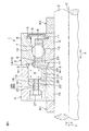
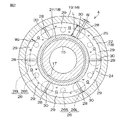
図1は、本発明の一実施形態に係る転がり軸受装置1の断面図である。図2は、図1のグリース貯留部材4の断面図であって、転がり軸受装置1を図1のII−II線で切断したときに現れる断面に対応する面を示している。
転がり軸受装置1は、たとえば工作機械の主軸(転がり軸受が支持される軸)2を支持する装置である。
Hereinafter, embodiments of the present invention will be described in detail with reference to the accompanying drawings.
FIG. 1 is a cross-sectional view of a rolling bearing device 1 according to an embodiment of the present invention. FIG. 2 is a cross-sectional view of the
The rolling bearing device 1 is a device that supports, for example, a main shaft (a shaft on which a rolling bearing is supported) 2 of a machine tool.
図1を参照して、転がり軸受装置1は、アンギュラ玉軸受からなる転がり軸受3と、転がり軸受3に隣接して設けられた本発明の間座の一例としてのグリース貯留部材4とを含む。
図1に示すように、転がり軸受3は、主軸2に外嵌された内輪5と、工作機械のハウジング(図示せず)に内嵌された外輪6と、内輪5と外輪6との間に介在する転動体7と、複数の転動体7を円周方向Yに一定間隔おきに保持する円筒状の保持器8と、内輪5と外輪6と間の環状空間の軸方向(主軸2の軸方向)Xの一方端(図1の右端であって、グリース貯留部材4とは反対側の端部)を密封するシール9とを含む。なお、図1では、転がり軸受3としてアンギュラ型の玉軸受を採用しているが、これに代えて深溝玉軸受を採用してもよく、その他、円筒ころ軸受や円すいころ軸受等を用いてもよい。
Referring to FIG. 1, a rolling bearing device 1 includes a rolling
As shown in FIG. 1, the rolling
内輪5の外周の軸方向Xの中央部には、転動体7を転走させるための内輪軌道面10が形成されている。また、内輪5の外周の軸方向Xの両端部には、第1シール溝11が形成されている。軸方向Xに関してグリース貯留部材4から遠い側(図1の右側)の第1シール溝11には、シール9の内周部(シールリップ)が嵌っている。
外輪6の内周の軸方向Xの中央部には、転動体7を転走させるための外輪軌道面12が形成されている。外輪6の内周の軸方向Xの両端部には、第2シール溝13が形成されている。軸方向Xに関してグリース貯留部材4から遠い側(図1の右側)の第2シール溝13には、シール9の外周部(シールリップ)が嵌っている。
An inner
An outer
軸方向Xに関してグリース貯留部材4に近い側(図1の左側)の第2シール溝13は、グリースGを溜めるための環状溝14として機能する。環状溝14は、外輪6のグリース貯留部材4に近い側の端部に形成された環状の凹部によって構成されている。環状溝14には予め初期潤滑用のグリースGが充填されている。
図1および図2を参照して、グリース貯留部材4は、主軸2に外嵌された内輪間座15と、内輪間座15との間に環状空間17が形成されるように内輪間座15を取り囲んで形成され、工作機械のハウジング(図示せず)に内嵌された外輪間座16と、内輪間座15と外輪間座16との間の環状空間17に配置された貯油環18とを含む。
The
Referring to FIGS. 1 and 2, the
内輪間座15は、主軸2の外周面に接する円筒状に形成されている。主軸2に外嵌された内輪間座15は、図1に示すように、軸方向Xの一方側端面が内輪5の端面に接した状態で位置決めされている。この位置決めは、内輪5および内輪間座15が連なった円筒体を、軸方向Xの両側から挟み込む間座K1,K2によってなされている。間座K1,K2は、それぞれ、主軸2に固定されている。
The
外輪間座16は、筒状の周壁19および当該周壁19の軸方向の一端側周縁から径方向内側に延びる円環板状の底壁20を一体的に有する有底円筒状に形成されている。底壁20の中央開口を介して外輪間座16を内輪間座15に外嵌することによって、外輪間座16と内輪間座15との間には、転がり軸受3に面する側が開放され、その反対側が底壁20で閉塞された環状空間17が区画されている。なお、以下において「外輪間座16の軸方向」とは、外輪間座16の周壁19の軸方向を指すものとし、この実施形態では、主軸2の軸方向Xに一致する。
The
また、外輪間座16は、図1に示すように、軸方向Xの一方側端面が外輪6の端面に接した状態で位置決めされている。この位置決めは、たとえば、ハウジング(図示せず)に固定された位置決め部材(図示せず)によってなされている。
貯油環18は、環状空間17の内周面を形成する内輪間座15に沿う円筒部21と、当該円筒部21の軸方向に関して、外輪間座16の底壁20側の周縁から径方向外側に延びる円環板状の奥側フランジ部22と、その反対側の周縁から径方向外側に延びる円環板状の供給側フランジ部23とを一体的に有している。外輪間座16の周壁19、貯油環18を構成する円筒部21、奥側フランジ部22および供給側フランジ部23によって、転がり軸受3に面する開口24を有する環状一体なグリース溜り25が区画されている。
Further, as shown in FIG. 1, the
The
また、貯油環18の供給側フランジ部23は、転がり軸受3の内部、すなわち内輪5と外輪6との間に入り込むことによって、環状溝14の内方領域に位置している。この供給側フランジ部23は、奥側フランジ部22よりも小径に形成されている。具体的には、奥側フランジ部22は、環状空間17に貯油環18を収容したときに、その外周面が外輪間座16の周壁19に接するように、環状空間17にほぼぴったりと収まる径で形成されている。一方、供給側フランジ23は、この奥側フランジ部22よりも小径であり、これにより、供給側フランジ23と外輪間座16の周壁19との間に環状の隙間が形成され、この隙間がグリース溜り25と転がり軸受3の内部(環状溝14)とを流通可能にする本発明の流通路の一例としての開口24を形成している。
The supply-
また、グリース貯留部材4には、外輪間座16の底壁20および貯油環18の奥側フランジ部22を連続して貫通する開口26が形成されている。この実施形態では、開口26は、グリース貯留部材4の周方向に沿って一定間隔おきに形成された、相対的に大きな第1開口26Lと、第1開口26Lよりも小さな第2開口26Sとを含む。たとえば、第1開口26Lは、貯油環18の径方向に関するグリース溜り25の幅とほぼ同じ大きさの径で形成されている。なお、第1開口26Lおよび第2開口26Sは、図2に示すように交互に配置されていてもよいし、それぞれが複数個固まって配置されていてもよい。
In addition, the
各開口26L,26Sの内周面には、ねじが切られている。当該ねじにボルト27を螺合することによって、貯油環18は外輪間座16に固定されている。
グリース溜り25および環状溝14に充填されたグリースGとしては、ウレア化合物、Baコンプレックス石鹸またはLiコンプレックス石鹸等を増ちょう剤とし、エステル、ポリアルファオレフィン等を基油としたものを用いることができる。また、この実施形態では、後述するようにグリースGに一定形状の溝28を形成する必要がある。そこで、グリースGが流動して溝28が塞がれることを防止するため、グリースGにはある程度の粘性を持たせておくことが好ましい。
Screws are formed on the inner peripheral surfaces of the
As the grease G filled in the
図2を参照して、グリースGには、溝28が形成されている。溝28は、外輪間座16の周方向に沿って一定間隔おきに複数形成されている。たとえば、図2では、溝28は、外輪間座16の周方向周りの60度おきに合計6つ形成され、それぞれが、第1開口26Lに対向するように配置されている。
各溝28は、グリースGの開口24に面する側(図1参照)から外輪間座16の軸方向に沿ってグリース溜り25の奥側に掘り込まれた軸方向の溝である。
Referring to FIG. 2, groove 28 is formed in grease G. A plurality of
Each
また、各溝28は、外輪間座16の径方向に沿って長手方向を有している。つまり、溝28は、図2に示すように、外輪間座16の軸方向から溝28を見たときに、外輪間座16の軸線から外周へ向かう径方向に沿って相対的に長い長さLを有し、外輪間座16の軸線周りの周方向に沿って長さLよりも短い幅Wを有している。特に、長さLは、外輪間座16の径方向に関して、溝28を貯油環18の供給側フランジ部23(図1参照)にオーバーラップさせることによって、グリース溜り25の開口24の周方向の開口幅W2よりも大きくなっていることが好ましい。
Each
より具体的には、この実施形態では、各溝28は、外輪間座16の軸方向に関して、グリース溜り25の開口24から貯油環18の奥側フランジ部22に至るまでの全範囲に亘って形成され、かつ、外輪間座16の径方向に関して、貯油環18の円筒部21から外輪間座16の周壁19に至るまでの全範囲に亘って形成されている。これにより、グリースGは、外輪間座16の所定箇所において各溝28によって完全に分断され、外輪間座16の周方向に沿って複数のセクション29(図2では、6つのセクション)に分割されている。各グリースGのセクション29は、外輪間座16の周方向に沿う両端部における端面30(溝28によって形成されたグリースGの表面)が、それぞれ、転がり軸受3に対する開口24の対向面積よりも広い面積で溝28に露出している。
More specifically, in this embodiment, each
なお、溝28の形状は、特に制限されないが、たとえば、図2に示すような平板状であってもよいし、楕円柱状、三角柱状等であってもよい。
図3は、グリースGに含まれる基油の流れを説明するための図であって、図3(a)は図1の要部を拡大した断面図であり、図3(b)は転がり軸受装置1を図3(a)のIIIb−IIIb線で切断したときに現れる断面図である。
The shape of the
3 is a view for explaining the flow of the base oil contained in the grease G. FIG. 3 (a) is an enlarged cross-sectional view of the main part of FIG. 1, and FIG. 3 (b) is a rolling bearing. It is sectional drawing which appears when the apparatus 1 is cut | disconnected by the IIIb-IIIb line | wire of Fig.3 (a).
次に、グリース溜り25に充填されたグリースGの基油の流れを説明する。
図3に示すように、この転がり軸受装置1では、転がり軸受3の環状溝14に初期潤滑用のグリースGが充填されていると共に、グリース溜り25に補給用のグリースGが充填されている。この環状溝14のグリースGとグリース溜り25のグリースGとは、互いに繋がっている。そのため、転がり軸受3の運転によって環状溝14内のグリースGの基油が消費されると、その消費に従って、グリース溜り25に溜められたグリースGの基油が、グリースGの増ちょう剤の毛細管現象によって、転がり軸受3側へと浸透移動する。
Next, the flow of the base oil of the grease G filled in the
As shown in FIG. 3, in the rolling bearing device 1, the
この際、グリース溜り25のグリースGに溝28が形成されていて、グリースGの端面30が溝28に露出していることから、グリースGの基油の供給が、グリースGの開口24に面する領域よりも当該溝28に露出する端面30から優先的に行われる。これにより、グリースGの端面30側から基油が消費されて端面30が窪み、溝28が両側に膨出するように拡大する(図3(b)参照)。この拡大に伴って、図3(a)および図3(b)に実線矢印で示すように、グリース溜り25の奥側から開口24へと向かう外輪間座16の軸方向Xに基油の流れが形成される。その結果、グリース溜り25の奥側のグリースGの基油を有効に利用して、転がり軸受3(環状溝14)に基油を順次供給することができる。そのため、外輪間座16の周方向に沿ってグリースGに割れが生じることを抑制でき、また、たとえグリース割れが生じても、転がり軸受3の近傍での基油の枯渇を防止することができる。よって、転がり軸受3へ、グリースGの基油を長期に亘って供給し続けることができ、転がり軸受3の潤滑性能の高寿命化を図ることができる。しかも、グリース溜り25のグリースGに溝28を形成するだけでよいので、転がり軸受装置1の構造が複雑化することを防止することもできる。
At this time, since the
しかも、この実施形態では、各溝28は、外輪間座16の軸方向に関して、グリース溜り25の開口24から貯油環18の奥側フランジ部22に至るまでの全範囲に亘って形成され(図3(b)参照)、かつ、外輪間座16の径方向に関して、貯油環18の円筒部21から外輪間座16の周壁19に至るまでの全範囲に亘って形成されている(図2参照)。これにより、限られた大きさのグリース溜りGにおいて、グリースGの端面30の表面積を最大限にすることができるので、グリース溜り25の奥側から開口24へと向かう外輪間座16の軸方向Xに基油の流れを効率よく発生させることができる。
Moreover, in this embodiment, each
また、溝28が複数形成されており、この構成によっても、グリースGの端面30の合計の表面積を広くすることができ、グリース溜り25の奥側から開口24へと向かう外輪間座16の軸方向Xに基油の流れを効率よく発生させることができる。
また、グリースGが、各溝28によって完全に分断されて複数のセクション29に分割されている。つまり、一つのセクション29は、その両隣のセクション29とは溝28によって物理的に分離されている。そのため、一つのセクション29にグリース割れが生じても、当該グリース割れの伝播は、当該グリース割れの生じたセクション29を挟む溝28で収束するので、当該グリース割れを一つのセクション29に留めることができる。その結果、当該セクション29の両隣のセクション29においては、グリース割れの影響を受けず、グリースGの基油を継続して供給することができる。
Also, a plurality of
Further, the grease G is completely divided by the
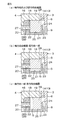
図4は、図1のグリースGの溝28の形成に関連する工程を工程順に説明するための転がり軸受装置1の断面図である。
上記したグリースGの溝28は、たとえば、図4(a)〜図4(c)に示す工程によって形成することができる。
具体的には、まず、内輪間座15、外輪間座16および貯油環18を互いに嵌め合うことによってグリース貯留部材4を組み立てた後、図4(a)に示すように、開口26(たとえば、第1開口26L)を介して、外輪間座16の裏面側(グリース溜り25の反対側)からグリース溜り25内にスペーサ31を挿入する。このスペーサ31は、事前に設計された溝28の形状と同一形状で形成されている。
FIG. 4 is a cross-sectional view of the rolling bearing device 1 for explaining the steps related to the formation of the
The
Specifically, first, after assembling the
次に、図4(b)に示すように、開口24を介して、グリース溜り25にグリースGを充填する。この際、グリースGは、スペーサ31を避けるように充填される。
そして、図4(c)に示すように、挿入に用いた開口26を利用して、スペーサ31を外輪間座16の裏面側へ抜き取る。これにより、グリース溜り25には、スペーサ31が配置されていた位置に、グリースGを分断する溝28が形成される。
Next, as shown in FIG. 4B, the grease G is filled in the
Then, as shown in FIG. 4C, the
このように、グリースGの溝28は、グリース溜り25へのスペーサ31の出し入れだけという簡単な作業で形成することができる。
以上、本発明の一実施形態について説明したが、本発明は他の形態で実施することもできる。
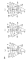
たとえば、前述の実施形態では、図5(a)に示すように、各溝28は、外輪間座16の軸方向に関して、グリース溜り25の開口24から貯油環18の奥側フランジ部22に至るまでの全範囲に亘って形成され、かつ、外輪間座16の径方向に関して、貯油環18の円筒部21から外輪間座16の周壁19に至るまでの全範囲に亘って形成されている例を挙げて説明した。しかし、各溝28は、たとえば、図5(b)に示すように、外輪間座16の軸方向に関して上記全範囲に形成されている一方、外輪間座16の径方向に関しては、その一部分(たとえば、貯油環18の円筒部21と間隔を空けるように、外輪間座16の周壁19から貯油環18の円筒部21に至る過程の途中まで)のみに形成されていてもよい。また、各溝28は、たとえば、図5(c)に示すように、外輪間座16の径方向に関して上記全範囲に形成されている一方、外輪間座16の軸方向に関しては、その一部分(たとえば、貯油環18の奥側フランジ部22と間隔を空けるように、グリース溜り25の開口24から貯油環18の奥側フランジ部22に至る過程の途中まで)のみに形成されていてもよい。
As described above, the
As mentioned above, although one Embodiment of this invention was described, this invention can also be implemented with another form.
For example, in the above-described embodiment, as shown in FIG. 5A, each
また、グリース溜り25の一例として、グリース溜り25が環状で一体である場合を例に挙げて説明したが、グリース溜り25は、外輪間座16の周方向に沿って複数室に分離された構造であってもよい。
また、前述の実施形態では、内輪5および内輪間座15が、主軸2に伴って回転する回転側であり、外輪6および外輪間座16が、ハウジング(図示しない)に固定される静止状態にある固定側である場合を例に挙げて説明した。しかし、外輪6および外輪間座16を回転側とし、内輪5および内輪間座15を固定側とする場合にも、本願発明を適用することができる。
Further, as an example of the
In the above-described embodiment, the
その他、特許請求の範囲内で種々の変更を加えることが可能である。 In addition, various modifications can be made within the scope of the claims.
1…転がり軸受装置、3…転がり軸受、4…グリース貯留部材、5…内輪、6…外輪、7…転動体、15…内輪間座、16…外輪間座、18…貯油環、22…奥側フランジ部、24…開口、25…グリース溜り、28…溝、31…スペーサ、G…グリース DESCRIPTION OF SYMBOLS 1 ... Rolling bearing apparatus, 3 ... Rolling bearing, 4 ... Grease storage member, 5 ... Inner ring, 6 ... Outer ring, 7 ... Rolling body, 15 ... Inner ring spacer, 16 ... Outer ring spacer, 18 ... Oil storage ring, 22 ... Back Side flange, 24 ... opening, 25 ... grease reservoir, 28 ... groove, 31 ... spacer, G ... grease
Claims (4)
前記転がり軸受の軸方向一方側に隣接配置された環状の間座であって、その周方向に沿う溝状に形成されたグリース溜り、および前記グリース溜りと前記転がり軸受内部とを連通させる流通路が形成された間座と、
前記グリース溜りに収容されたグリースとを含み、
前記グリースには、前記流通路側から前記間座の軸方向に沿って前記グリース溜りの奥側に掘り込まれた軸方向の溝が、前記間座の周方向に沿って間隔を空けて複数形成されており、
前記グリースは、前記溝に露出する端面を有しており、
前記グリースは、前記間座の所定箇所において各前記溝によって完全に分断され、前記間座の周方向に沿って複数のセクションに分割されている、転がり軸受装置。 A rolling bearing having an inner ring, an outer ring, and a plurality of rolling elements disposed between the inner and outer rings;
An annular spacer disposed adjacent to one side in the axial direction of the rolling bearing, a grease reservoir formed in a groove shape along the circumferential direction thereof, and a flow passage for communicating the grease reservoir and the inside of the rolling bearing A spacer formed with,
Grease contained in the grease reservoir,
In the grease, a plurality of axial grooves dug into the depth side of the grease reservoir along the axial direction of the spacer from the flow passage side are formed at intervals along the circumferential direction of the spacer. Has been
The grease has an end surface exposed in the groove ;
The rolling bearing device, wherein the grease is completely divided by the grooves at predetermined positions of the spacer and divided into a plurality of sections along a circumferential direction of the spacer .
環状の間座であって、その周方向に沿う溝状に形成されたグリース溜り、および前記グリース溜りを転がり軸受内に供給するための流通路が形成された間座の前記流通路とは反対側から前記間座の軸方向に沿って前記間座の前記流通路側に向かってスペーサを挿入する工程と、
前記スペーサの挿入後、前記グリース溜りにグリースを充填する工程と、
前記グリースの充填後、前記スペーサを前記グリース溜りから抜き取ることによって、前記グリースにおける前記スペーサが配置されていた位置に溝を形成する工程とを含む、転がり軸受装置の製造方法。 It is a manufacturing method of the rolling bearing device according to any one of claims 1 to 3,
An annular spacer, which is opposite to the flow passage in the spacer, in which a grease reservoir formed in a groove shape along the circumferential direction thereof and a flow passage for supplying the grease reservoir into the rolling bearing are formed Inserting a spacer from the side along the axial direction of the spacer toward the flow passage side of the spacer;
Filling the grease reservoir with the grease after inserting the spacer;
And a step of forming a groove at a position where the spacer is disposed in the grease by removing the spacer from the grease reservoir after filling with the grease.
Priority Applications (4)
| Application Number | Priority Date | Filing Date | Title |
|---|---|---|---|
| JP2013165303A JP6414656B2 (en) | 2013-08-08 | 2013-08-08 | Rolling bearing device and method of manufacturing rolling bearing device |
| US14/448,518 US9169873B2 (en) | 2013-08-08 | 2014-07-31 | Rolling bearing unit |
| EP14180225.6A EP2835546B1 (en) | 2013-08-08 | 2014-08-07 | Rolling bearing unit with grease reservoir |
| CN201410387942.XA CN104343824B (en) | 2013-08-08 | 2014-08-08 | Rolling bearing system |
Applications Claiming Priority (1)
| Application Number | Priority Date | Filing Date | Title |
|---|---|---|---|
| JP2013165303A JP6414656B2 (en) | 2013-08-08 | 2013-08-08 | Rolling bearing device and method of manufacturing rolling bearing device |
Publications (2)
| Publication Number | Publication Date |
|---|---|
| JP2015034587A JP2015034587A (en) | 2015-02-19 |
| JP6414656B2 true JP6414656B2 (en) | 2018-10-31 |
Family
ID=51298592
Family Applications (1)
| Application Number | Title | Priority Date | Filing Date |
|---|---|---|---|
| JP2013165303A Expired - Fee Related JP6414656B2 (en) | 2013-08-08 | 2013-08-08 | Rolling bearing device and method of manufacturing rolling bearing device |
Country Status (4)
| Country | Link |
|---|---|
| US (1) | US9169873B2 (en) |
| EP (1) | EP2835546B1 (en) |
| JP (1) | JP6414656B2 (en) |
| CN (1) | CN104343824B (en) |
Families Citing this family (4)
| Publication number | Priority date | Publication date | Assignee | Title |
|---|---|---|---|---|
| US9933016B2 (en) | 2014-04-15 | 2018-04-03 | Jtekt Corporation | Rolling bearing device |
| JP6390399B2 (en) * | 2014-12-11 | 2018-09-19 | 株式会社ジェイテクト | Rolling bearing device, method of manufacturing rolling bearing device, and jig |
| GB201500700D0 (en) | 2015-01-16 | 2015-03-04 | Rolls Royce Plc | Rolling-element bearing and method of countering load applied to rolling-element bearing |
| JP7362239B2 (en) * | 2018-02-13 | 2023-10-17 | Ntn株式会社 | Bearing devices and spindle devices |
Family Cites Families (14)
| Publication number | Priority date | Publication date | Assignee | Title |
|---|---|---|---|---|
| US3019065A (en) | 1959-11-09 | 1962-01-30 | Howard B Neeley | Grease container |
| JPH07269573A (en) * | 1994-03-31 | 1995-10-17 | Ntn Corp | Needle roller bearing |
| JPH08294247A (en) * | 1995-04-21 | 1996-11-05 | Toshiba Corp | Bearing device of rotating electric machine |
| JPH0923607A (en) * | 1995-07-06 | 1997-01-21 | Toshiba Corp | Bearing |
| JP4199850B2 (en) * | 1998-07-14 | 2008-12-24 | 日本トムソン株式会社 | Linear motion guide unit with lubrication plate |
| JP2003194074A (en) * | 2001-12-26 | 2003-07-09 | Nsk Ltd | Lubricating mechanism for bearing device |
| JP2005106245A (en) * | 2003-10-01 | 2005-04-21 | Ntn Corp | Bearing with lubricating mechanism, and spindle device for machine tool using it |
| JP2005180629A (en) | 2003-12-22 | 2005-07-07 | Ntn Corp | Rolling bearing |
| US7918606B2 (en) * | 2004-10-08 | 2011-04-05 | Ntn Corporation | Rolling bearing |
| JP2006226427A (en) * | 2005-02-18 | 2006-08-31 | Ntn Corp | Rolling bearing |
| JP2007078115A (en) * | 2005-09-15 | 2007-03-29 | Ntn Corp | Rolling bearing |
| US7874733B2 (en) * | 2006-01-05 | 2011-01-25 | Ntn Corporation | Rolling bearing |
| EP2306037B1 (en) | 2008-07-25 | 2018-05-16 | JTEKT Corporation | Roller bearing device, and method for forming lubrication means for the device |
| CN102762880A (en) * | 2010-02-17 | 2012-10-31 | Ntn株式会社 | Rolling bearing lubrication structure and rolling bearing |
-
2013
- 2013-08-08 JP JP2013165303A patent/JP6414656B2/en not_active Expired - Fee Related
-
2014
- 2014-07-31 US US14/448,518 patent/US9169873B2/en not_active Expired - Fee Related
- 2014-08-07 EP EP14180225.6A patent/EP2835546B1/en not_active Not-in-force
- 2014-08-08 CN CN201410387942.XA patent/CN104343824B/en not_active Expired - Fee Related
Also Published As
| Publication number | Publication date |
|---|---|
| EP2835546A2 (en) | 2015-02-11 |
| CN104343824B (en) | 2018-08-07 |
| CN104343824A (en) | 2015-02-11 |
| EP2835546A3 (en) | 2015-06-24 |
| US20150043853A1 (en) | 2015-02-12 |
| EP2835546B1 (en) | 2017-12-20 |
| JP2015034587A (en) | 2015-02-19 |
| US9169873B2 (en) | 2015-10-27 |
Similar Documents
| Publication | Publication Date | Title |
|---|---|---|
| JP6414656B2 (en) | Rolling bearing device and method of manufacturing rolling bearing device | |
| JP5549587B2 (en) | Rolling bearing device and method for forming lubricating means thereof | |
| JP6016632B2 (en) | Rolling bearings and spindles for machine tools | |
| RU2585125C2 (en) | Rolling bearing assembly | |
| WO2016010057A1 (en) | Ball bearing | |
| JP2010164122A (en) | Angular ball bearing | |
| US9933016B2 (en) | Rolling bearing device | |
| JP2016023648A (en) | Ball bearing | |
| JP5816061B2 (en) | Rolling bearing lubrication system | |
| JP5933458B2 (en) | Rolling bearing cage | |
| CN109937309B (en) | Bearing device | |
| JP5912413B2 (en) | Solid lubricant embedded bearing and manufacturing method thereof | |
| JP6076610B2 (en) | Roller bearing cage | |
| JP6414663B2 (en) | Rolling bearing device | |
| JP2014111954A (en) | Rolling bearing device | |
| JP2008240826A (en) | Ball bearing and retainer | |
| JP2016044758A (en) | Rolling bearing | |
| JP6460368B2 (en) | Rolling bearing device | |
| JP6390890B2 (en) | Rolling bearing device | |
| JP6390399B2 (en) | Rolling bearing device, method of manufacturing rolling bearing device, and jig | |
| WO2018088226A1 (en) | Bearing device | |
| JP2010002027A (en) | Cylindrical roller bearing and cylindrical roller bearing device | |
| JP2009168140A (en) | Rolling bearing device | |
| JP2008180308A (en) | Tapered roller bearing | |
| JP2005155877A (en) | Rolling bearing |
Legal Events
| Date | Code | Title | Description |
|---|---|---|---|
| A621 | Written request for application examination |
Free format text: JAPANESE INTERMEDIATE CODE: A621 Effective date: 20160720 |
|
| A977 | Report on retrieval |
Free format text: JAPANESE INTERMEDIATE CODE: A971007 Effective date: 20170515 |
|
| A131 | Notification of reasons for refusal |
Free format text: JAPANESE INTERMEDIATE CODE: A131 Effective date: 20170629 |
|
| A521 | Request for written amendment filed |
Free format text: JAPANESE INTERMEDIATE CODE: A523 Effective date: 20170822 |
|
| A131 | Notification of reasons for refusal |
Free format text: JAPANESE INTERMEDIATE CODE: A131 Effective date: 20180201 |
|
| A521 | Request for written amendment filed |
Free format text: JAPANESE INTERMEDIATE CODE: A523 Effective date: 20180314 |
|
| TRDD | Decision of grant or rejection written | ||
| A01 | Written decision to grant a patent or to grant a registration (utility model) |
Free format text: JAPANESE INTERMEDIATE CODE: A01 Effective date: 20180906 |
|
| A61 | First payment of annual fees (during grant procedure) |
Free format text: JAPANESE INTERMEDIATE CODE: A61 Effective date: 20180919 |
|
| R150 | Certificate of patent or registration of utility model |
Ref document number: 6414656 Country of ref document: JP Free format text: JAPANESE INTERMEDIATE CODE: R150 |
|
| LAPS | Cancellation because of no payment of annual fees |