JP6414115B2 - Stepping motor, motor drive device, and time display device - Google Patents
Stepping motor, motor drive device, and time display device Download PDFInfo
- Publication number
- JP6414115B2 JP6414115B2 JP2016061165A JP2016061165A JP6414115B2 JP 6414115 B2 JP6414115 B2 JP 6414115B2 JP 2016061165 A JP2016061165 A JP 2016061165A JP 2016061165 A JP2016061165 A JP 2016061165A JP 6414115 B2 JP6414115 B2 JP 6414115B2
- Authority
- JP
- Japan
- Prior art keywords
- coil
- stator
- coils
- rotor
- stepping motor
- Prior art date
- Legal status (The legal status is an assumption and is not a legal conclusion. Google has not performed a legal analysis and makes no representation as to the accuracy of the status listed.)
- Active
Links
- 238000004804 winding Methods 0.000 claims description 26
- 230000010287 polarization Effects 0.000 claims description 11
- 239000000758 substrate Substances 0.000 description 55
- 230000004907 flux Effects 0.000 description 24
- 125000006850 spacer group Chemical group 0.000 description 22
- 230000007246 mechanism Effects 0.000 description 14
- 229910000889 permalloy Inorganic materials 0.000 description 13
- 238000010586 diagram Methods 0.000 description 11
- 239000000463 material Substances 0.000 description 10
- 238000001514 detection method Methods 0.000 description 9
- 230000035699 permeability Effects 0.000 description 7
- 239000011347 resin Substances 0.000 description 7
- 229920005989 resin Polymers 0.000 description 7
- XEEYBQQBJWHFJM-UHFFFAOYSA-N iron Substances [Fe] XEEYBQQBJWHFJM-UHFFFAOYSA-N 0.000 description 4
- 238000000034 method Methods 0.000 description 4
- 230000000694 effects Effects 0.000 description 3
- 238000004519 manufacturing process Methods 0.000 description 3
- 230000004048 modification Effects 0.000 description 3
- 238000012986 modification Methods 0.000 description 3
- 238000010521 absorption reaction Methods 0.000 description 2
- 239000011248 coating agent Substances 0.000 description 2
- 238000000576 coating method Methods 0.000 description 2
- 239000006185 dispersion Substances 0.000 description 2
- 238000003780 insertion Methods 0.000 description 2
- 230000037431 insertion Effects 0.000 description 2
- 230000001788 irregular Effects 0.000 description 2
- 229920006395 saturated elastomer Polymers 0.000 description 2
- 230000000295 complement effect Effects 0.000 description 1
- 238000013461 design Methods 0.000 description 1
- 230000005669 field effect Effects 0.000 description 1
- 230000010354 integration Effects 0.000 description 1
- 229910052742 iron Inorganic materials 0.000 description 1
- 230000005415 magnetization Effects 0.000 description 1
- 230000002093 peripheral effect Effects 0.000 description 1
- 230000008569 process Effects 0.000 description 1
- 238000012545 processing Methods 0.000 description 1
- 230000001681 protective effect Effects 0.000 description 1
- 229910052761 rare earth metal Inorganic materials 0.000 description 1
- 150000002910 rare earth metals Chemical class 0.000 description 1
- 230000009467 reduction Effects 0.000 description 1
- 230000004044 response Effects 0.000 description 1
- 229910000938 samarium–cobalt magnet Inorganic materials 0.000 description 1
- 238000003466 welding Methods 0.000 description 1
Images


Classifications
-
- H—ELECTRICITY
- H02—GENERATION; CONVERSION OR DISTRIBUTION OF ELECTRIC POWER
- H02P—CONTROL OR REGULATION OF ELECTRIC MOTORS, ELECTRIC GENERATORS OR DYNAMO-ELECTRIC CONVERTERS; CONTROLLING TRANSFORMERS, REACTORS OR CHOKE COILS
- H02P25/00—Arrangements or methods for the control of AC motors characterised by the kind of AC motor or by structural details
- H02P25/02—Arrangements or methods for the control of AC motors characterised by the kind of AC motor or by structural details characterised by the kind of motor
- H02P25/06—Linear motors
- H02P25/064—Linear motors of the synchronous type
- H02P25/066—Linear motors of the synchronous type of the stepping type
-
- H—ELECTRICITY
- H02—GENERATION; CONVERSION OR DISTRIBUTION OF ELECTRIC POWER
- H02K—DYNAMO-ELECTRIC MACHINES
- H02K37/00—Motors with rotor rotating step by step and without interrupter or commutator driven by the rotor, e.g. stepping motors
-
- G—PHYSICS
- G04—HOROLOGY
- G04C—ELECTROMECHANICAL CLOCKS OR WATCHES
- G04C3/00—Electromechanical clocks or watches independent of other time-pieces and in which the movement is maintained by electric means
- G04C3/14—Electromechanical clocks or watches independent of other time-pieces and in which the movement is maintained by electric means incorporating a stepping motor
-
- H—ELECTRICITY
- H02—GENERATION; CONVERSION OR DISTRIBUTION OF ELECTRIC POWER
- H02K—DYNAMO-ELECTRIC MACHINES
- H02K1/00—Details of the magnetic circuit
- H02K1/02—Details of the magnetic circuit characterised by the magnetic material
-
- H—ELECTRICITY
- H02—GENERATION; CONVERSION OR DISTRIBUTION OF ELECTRIC POWER
- H02K—DYNAMO-ELECTRIC MACHINES
- H02K1/00—Details of the magnetic circuit
- H02K1/06—Details of the magnetic circuit characterised by the shape, form or construction
- H02K1/12—Stationary parts of the magnetic circuit
- H02K1/14—Stator cores with salient poles
-
- H—ELECTRICITY
- H02—GENERATION; CONVERSION OR DISTRIBUTION OF ELECTRIC POWER
- H02K—DYNAMO-ELECTRIC MACHINES
- H02K1/00—Details of the magnetic circuit
- H02K1/06—Details of the magnetic circuit characterised by the shape, form or construction
- H02K1/22—Rotating parts of the magnetic circuit
- H02K1/27—Rotor cores with permanent magnets
-
- H—ELECTRICITY
- H02—GENERATION; CONVERSION OR DISTRIBUTION OF ELECTRIC POWER
- H02K—DYNAMO-ELECTRIC MACHINES
- H02K37/00—Motors with rotor rotating step by step and without interrupter or commutator driven by the rotor, e.g. stepping motors
- H02K37/10—Motors with rotor rotating step by step and without interrupter or commutator driven by the rotor, e.g. stepping motors of permanent magnet type
- H02K37/12—Motors with rotor rotating step by step and without interrupter or commutator driven by the rotor, e.g. stepping motors of permanent magnet type with stationary armatures and rotating magnets
- H02K37/14—Motors with rotor rotating step by step and without interrupter or commutator driven by the rotor, e.g. stepping motors of permanent magnet type with stationary armatures and rotating magnets with magnets rotating within the armatures
-
- H—ELECTRICITY
- H02—GENERATION; CONVERSION OR DISTRIBUTION OF ELECTRIC POWER
- H02P—CONTROL OR REGULATION OF ELECTRIC MOTORS, ELECTRIC GENERATORS OR DYNAMO-ELECTRIC CONVERTERS; CONTROLLING TRANSFORMERS, REACTORS OR CHOKE COILS
- H02P8/00—Arrangements for controlling dynamo-electric motors rotating step by step
- H02P8/02—Arrangements for controlling dynamo-electric motors rotating step by step specially adapted for single-phase or bi-pole stepper motors, e.g. watch-motors, clock-motors
Landscapes
- Engineering & Computer Science (AREA)
- Power Engineering (AREA)
- Physics & Mathematics (AREA)
- General Physics & Mathematics (AREA)
- Electromechanical Clocks (AREA)
- Control Of Stepping Motors (AREA)
Description
本発明は、ステッピングモータ、モータ駆動装置及び時刻表示装置に関するものである。 The present invention relates to a stepping motor, a motor drive device, and a time display device.
従来、2つのコイルを備え、このコイルに適宜駆動パルスを印加することにより正逆転可能に構成されたステッピングモータが知られている。
例えば、特許文献1には、2つのコイルに同時又は順次に駆動パルスが印加することにより、2極着磁されたロータを所定のステップ角で回転させるステッピングモータが開示されている。
2. Description of the Related Art Conventionally, a stepping motor that includes two coils and is configured to be capable of forward and reverse rotation by appropriately applying drive pulses to the coils is known.
For example,
しかしながら、特許文献1に記載されているようなステッピングモータでは、ステッピングモータを回転させる際、2つのコイルの一方にのみ通電する期間と、2つのコイルの双方に通電する期間とが存在する。
このため、後者の期間に消費される電力が大きくなってしまうという問題があり、更なる低消費電力化が望まれていた。
However, in the stepping motor described in
For this reason, there is a problem that the power consumed during the latter period increases, and further reduction in power consumption has been desired.
本発明は以上のような事情に鑑みてなされたものであり、複数のコイルを備え、このコイルに駆動パルスを印加することによりロータを所定のステップ角で回転させる場合に、ロータの回転に必要なエネルギーをできる限り抑えて低消費電力化を可能とするステッピングモータ、モータ駆動装置及び時刻表示装置を提供することを目的とするものである。 The present invention has been made in view of the above circumstances, and is necessary for rotating the rotor when a plurality of coils are provided and the rotor is rotated at a predetermined step angle by applying drive pulses to the coils. An object of the present invention is to provide a stepping motor, a motor driving device, and a time display device that can reduce power consumption by suppressing as much energy as possible.
前記課題を解決するために、本発明に係るステッピングモータは、
径方向に2極着磁されたロータと、
第1部材で形成され、前記ロータを受容するロータ受容部を有するステータと、
前記第1部材とは異なる第2部材で形成され、前記ステータを挟んでほぼ左右対称位置に配置されるヨークと、
前記ステータと磁気的に結合して設けられた3つのコイルと、
を備え、
前記3つのコイルのうち、少なくとも1つは前記ステータの一部に巻き線を施すことで一体的に形成された一体型コイルであり、前記3つのコイルのうちの前記一体型コイル以外のコイルは前記ヨークの一部に巻き線を施すことで形成されたコイルであることを特徴としている。
In order to solve the above-described problem, a stepping motor according to the present invention includes:
A rotor with two poles in the radial direction;
A stator formed of a first member and having a rotor receiving portion for receiving the rotor;
A yoke formed of a second member different from the first member, and disposed in a substantially bilaterally symmetric position across the stator;
Three coils provided magnetically coupled to the stator;
With
Wherein of the three coils, at least one Ri Ah with integrated coil integrally formed by performing winding in a part of the stator, said three of the integrated coil other than the coil of the coil It is characterized by Oh Rukoto with coils formed by applying winding in a part of the yoke.
本発明によれば、複数のコイルを備え、このコイルに駆動パルスを印加することによりロータを所定のステップ角で回転させる場合に、ロータの回転に必要なエネルギーをできる限り抑えて低消費電力化を図ることができるという効果を奏する。 According to the present invention, when a plurality of coils are provided and the rotor is rotated at a predetermined step angle by applying a drive pulse to the coils, the energy required for rotating the rotor is suppressed as much as possible to reduce power consumption. There is an effect that can be achieved.
[第1の実施形態]
以下、図1(a)及び図1(b)から図9(a)〜図9(f)を参照しつつ、本発明に係るステッピングモータ及びモータ駆動装置の第1の実施形態について説明する。本実施形態に係るステッピングモータ及びモータ駆動装置は、例えば腕時計等の時刻表示装置(本実施形態では時計500を例示、図7参照)の指針を動作させる運針機構や日付機構等を駆動させるために適用される小型のモータ及びこれを駆動させる駆動装置であるが、本発明に係るステッピングモータ及びモータ駆動装置を適用可能な実施形態はこれに限定されるものではない。
[First Embodiment]
A first embodiment of a stepping motor and a motor drive device according to the present invention will be described below with reference to FIGS. 1 (a) and 1 (b) to 9 (a) to 9 (f). The stepping motor and the motor driving device according to the present embodiment are for driving a hand movement mechanism, a date mechanism, and the like that operate a pointer of a time display device such as a wristwatch (in this embodiment, a
図1(a)は、本実施形態におけるステッピングモータの平面図であり、図1(b)は、図1(a)における矢視b方向から見たステッピングモータの正面図である。
図1(a)に示すように、ステッピングモータ1は、ステータ(Stator;固定子)11と、ロータ(Rotor;回転子)15と、ステータ11と磁気的に結合して設けられた3つのコイルC1,C2,C3とを備えている。
Fig.1 (a) is a top view of the stepping motor in this embodiment, FIG.1 (b) is a front view of the stepping motor seen from the arrow b direction in Fig.1 (a).
As shown in FIG. 1A, a
ロータ15は、径方向に2極着磁された磁石である。図1(a)等では、ロータ15における白抜き部分をS極、斜線ハッチングを施した部分をN極とする。
本実施形態において、ロータ15はほぼ円盤状に形成されており、ロータ15の円中心には図示しない回転支軸が取り付けられている。
ロータ15に適用される磁石としては、例えば希土類磁石等(例えば、サマリウムコバルト磁石等)の永久磁石が好適に用いられるが、ロータ15として適用可能な磁石の種類はこれに限定されない。
ロータ15は、後述するステータ11のロータ受容部115に受容され、回転支軸を回転中心として回転可能に配置されている。なお、本実施形態において、ロータ15は、後述する3つのコイル(第1のコイルC1,第2のコイルC2,第3のコイルC3)のいずれか1つに順次に駆動パルスが印加されることによって、ロータ受容部115内で正転方向(すなわち時計回りの方向)及び逆転方向(すなわち反時計回りの方向)いずれの方向にも所定のステップ角(本実施形態では60度)で回転可能となっている。
回転支軸には例えば腕時計等の時刻表示装置(例えば、後述する時計500、図7参照)の指針を運針させるための輪列機構を構成する歯車等(図示せず)が連結されており、ロータ15が回転することにより、この歯車等を回転させるようになっている。
The
In the present embodiment, the
As the magnet applied to the
The
A gear or the like (not shown) that constitutes a train wheel mechanism for moving a pointer of a time display device such as a wristwatch (for example, a
図2(a)はステータの平面図であり、図2(b)は図2(a)における矢視b方向から見たステータの側面図であり、図2(c)は図2(a)に示すステータに第1のコイルC1とコイル基板16とを取り付けた状態を示す平面図であり、図2(d)は図2(c)における矢視d方向から見たステータの正面図である。
本実施形態において、ステータ11は、直状部111と、この直状部111の一端側から直状部111の延在方向と直交する方向に張り出す張出部112と、直状部111の他端側から直状部111の延在方向と直交する方向に張り出す張出部113と、を備えている。
2 (a) is a plan view of the stator, FIG. 2 (b) is a side view of the stator as seen from the direction of arrow b in FIG. 2 (a), and FIG. 2 (c) is FIG. 2 (a). FIG. 2D is a plan view showing a state where the first coil C1 and the
In the present embodiment, the
直状部111は、ステッピングモータ1におけるセンターヨークを構成するものである。
図2(c)及び図2(d)に示すように、直状部111には、巻き線を施すことで第1のコイルC1が形成されている。
ステッピングモータ1に設けられている3つのコイルC1,C2,C3のうち、少なくとも1つはステータ11の一部に巻き線を施すことで一体的に形成された一体型コイルとなっており、本実施形態では、ステータ11の直状部111に設けられた第1のコイルC1がこの一体型コイルとなっている。
また、図2(b)に示すように、第1のコイルC1が形成される直状部111は、張出部112,113よりも張出部112,113の厚み分だけ高さが高くなるように、磁束を飽和させないような幅の広い部分において潰し加工が施されていることが好ましい。
後述するように、張出部112,113には、第2のコイルC2が形成された第1のサイドヨーク12、第3のコイルC3が形成された第2のサイドヨーク13がそれぞれ係止され、ステッピングモータ1の組み立て状態においては、図1(a)等に示すように、3つのコイルC1,C2,C3が並列的に配置される。このとき、第1のサイドヨーク12及び第2のサイドヨーク13は、ステータ11の張出部112,113の上に重ねて配置されるため、第2のコイルC2及び第3のコイルC3が形成される部分(後述する直状部121,131)の高さも張出部112,113の厚み分だけステータ11よりも高くなる。この点、ステータ11の直状部111に、張出部112,113の厚み分だけ高さが高くなるように潰し加工を施すことにより、3つのコイルC1,C2,C3の高さ(ステッピングモータ1の厚み方向における高さ)をほぼ面一に揃えることができる。このため、ステッピングモータ1を実装する際に、よりコンパクトに狭い実装スペースにも配置することが可能となる。
The
As shown in FIGS. 2C and 2D, the first coil C1 is formed in the
Of the three coils C1, C2, and C3 provided in the
In addition, as shown in FIG. 2B, the
As will be described later, the
本実施形態のステータ11は、例えばパーマロイC(PC)等の高透磁率材料によって形成されている。
パーマロイCは、Ni=45、Fe=Balを材料成分としており、初透磁率60000μi、最大透磁率180000μm、飽和磁束密度0.65Bm(T)、保持力1.2Hc(A/m)、固有抵抗0.55μΩ.m以上である。
本実施形態では後述する第1のサイドヨーク12及び第2のサイドヨーク13を形成する材料として、パーマロイC(PC)よりも飽和磁束密度が高く磁束が飽和しにくいパーマロイB(PB)を用いている。
このため、ステータ11に形成される第1のコイルC1の巻き線数を第1のサイドヨーク12及び第2のサイドヨーク13に形成される第2のコイルC2及び第3のコイルC3の巻き線数と同じにするためには、第1のコイルC1を通過する磁束が飽和しないように、第1のサイドヨーク12及び第2のサイドヨーク13における直状部121,131よりもステータ11の直状部111の断面積(磁束の流れに直交する断面の断面積)をその分(具体的には、1.5倍から2倍程度)大きく形成して、十分な磁路を確保することが好ましい。
The
Permalloy C has Ni = 45 and Fe = Bal as material components, initial permeability 60000 μi, maximum permeability 180000 μm, saturation magnetic flux density 0.65 Bm (T), coercive force 1.2 Hc (A / m), specific resistance 0.55 μΩ. m or more.
In this embodiment, as a material for forming a
Therefore, the number of windings of the first coil C1 formed on the
張出部112の幅方向におけるほぼ中央部であり、ステッピングモータ1の組み立て状態において、ステータ11、第1のサイドヨーク12及び第2のサイドヨーク13の交点となる位置には、ほぼ円形の孔部であってロータ15が受容されるロータ受容部115が形成されている。
このロータ受容部115には、ロータ15の外周に沿って、ほぼ等間隔にステータ側静止部116が設けられている。ステータ側静止部116は、ロータ15の静止状態を維持させるものであり、本実施形態において、ステータ側静止部116は、ステータ11のロータ受容部115の内周面に形成された6つの凹部(すなわち、ノッチ;notch)である。
ロータ15は、いずれかのステータ側静止部116と、ロータ15の分極位置とが対向している状態において最もインデックストルク(保持トルク)が大きくなるため、駆動パルスが印加されていない非通電状態では、ロータ15は、図1(a)等に示すように、いずれかのステータ側静止部116と、ロータ15の分極位置とが対向する位置で静止する。
The overhanging
The
The
ステータ11の張出部112,113には、ステッピングモータ1をメインプレート3(図5(a)及び図5(b)参照)等にビス止め固定するためのビス19(図1(a)等参照)を挿通させるビス孔119が、それぞれ2つずつ設けられている。
また、ステータ11の張出部113には、張出部113における幅方向のほぼ中央部であってビス孔119を避ける位置にコイル基板16が搭載されている。コイル基板16には、第1のコイルC1の端子が接続される接続点t3及び接続点t4が設けられている。
本実施形態では、後述する第1のサイドヨーク12及び第2のサイドヨーク13のコイルC2,C3に対応して設けられるコイル基板17,18がビス孔119の片側半分を覆う程度の形状となっており、このビス孔119の周りでメイン基板2と接触できるような形状で2つの接続点t1,t4及びt2,t4が設けられている。コイル基板16は、これらコイル基板17,18を補完するようにビス孔119の他方側半分を覆う程度の形状に形成され、ビス孔119に対応する部分のみ切り欠かれているとともに、第1のコイルC1と接続される2つの接続点t3,t4がビス孔119に向かって延長されている。
このように、コイル基板16とコイル基板17,18とで、2つのビス孔119を両側から囲むように配置することにより、コイル基板16が配置されたステータ11とコイル基板17,18が配置された第1のサイドヨーク12及び第2のサイドヨーク13とを2つのビス19で締め付け固定することが可能となっている。
また、図2(d)等に示すように、張出部113とコイル基板16との間には、スペーサ4aが配置されている。スペーサ4aは、第1のコイルC1の高さとほぼ同じ高さに上面がくる厚みに形成されており、このスペーサ4aの上にコイル基板16を配置することでコイル基板16が第1のコイルC1の高さとほぼ同じかこれよりも多少高い位置に配置される。
Screws 19 (FIG. 1 (a), etc.) for fixing the stepping
In addition, the
In the present embodiment, the
In this way, by arranging the
Further, as shown in FIG. 2D and the like, a
本実施形態において、ステッピングモータ1の3つのコイルC1,C2,C3の端子はそれぞれコイル基板16,17,18のいずれかの接続点(すなわち、接続点t1〜t4)に接続され、後述のモータ駆動回路5(図6等参照)と電気的に接続される。
ここで、接続点とは、電気的、磁気的、機能的な接続点である。以下接続点t1,t2,t3,t4について同様である。
本実施形態では、この接続点のうちの一部が共通しており、具体的には、3つのコイルC1,C2,C3の各端子の片側の端子の接続点である接続点t4が3つのコイルC1,C2,C3に共通の接続点となっている。
これにより、4つの接続点で3つのコイルC1,C2,C3を制御することとなり、あるコイル(例えば第1のコイルC1)を起動させるときは共通化された接続点t4ともう一方の端子の接続点(例えば第1のコイルC1の場合には接続点t3)をON状態として当該コイル(例えば第1のコイルC1)を起動させ、他のコイル(例えば第2のコイルC2及び第3のコイルC3)の接続点t4以外の端子の接続点(例えば第2のコイルC2の接続点t1と第3のコイルC3の接続点t2)をOFF状態とすることにより、起動させるコイル(例えば第1のコイルC1)のみに電流を流すことが可能となる。
In the present embodiment, the terminals of the three coils C1, C2, and C3 of the stepping
Here, the connection point is an electrical, magnetic, or functional connection point. The same applies to the connection points t1, t2, t3, and t4.
In this embodiment, some of the connection points are common, and specifically, there are three connection points t4 that are connection points of terminals on one side of the terminals of the three coils C1, C2, and C3. This is a common connection point for the coils C1, C2, and C3.
As a result, the three coils C1, C2, and C3 are controlled at the four connection points. When a certain coil (for example, the first coil C1) is activated, the common connection point t4 and the other terminal are connected. The connection point (for example, the connection point t3 in the case of the first coil C1) is turned on to activate the coil (for example, the first coil C1) and other coils (for example, the second coil C2 and the third coil). C3) is connected to a terminal other than the connection point t4 (for example, the connection point t1 of the second coil C2 and the connection point t2 of the third coil C3) to an OFF state, thereby starting the coil (for example, the first coil It is possible to pass a current only through the coil C1).
図3(a)は、第1のサイドヨーク及び第2のサイドヨークの平面図であり、図3(b)は図3(a)に示す第1のサイドヨーク及び第2のサイドヨークにそれぞれ第2のコイルC2、第3のコイルC3及びコイル基板17,18を取り付けた状態を示す平面図であり、図3(c)は図2(b)における矢視c方向から見た第1のサイドヨーク及び第2のサイドヨークの正面図である。
図1(a)等に示すように、本実施形態において、第1のサイドヨーク12及び第3のサイドヨーク13は、ステータ11の直状部111を挟んでほぼ左右対称位置(本実施形態では、第1のサイドヨーク12が図1(a)における右側、第3のサイドヨーク13が図1(a)における左側)に配置される。
FIG. 3A is a plan view of the first side yoke and the second side yoke, and FIG. 3B is a plan view of the first side yoke and the second side yoke shown in FIG. It is a top view which shows the state which attached the 2nd coil C2, the 3rd coil C3, and the coil board |
As shown in FIG. 1A and the like, in the present embodiment, the
本実施形態の第1のサイドヨーク12及び第2のサイドヨーク13は、例えばパーマロイB(PB)等の高透磁率材料によって形成されている。
パーマロイBは、Ni=77〜78、Mo=5、Cu=4、Fe=Balを材料成分としており、初透磁率4500μi、最大透磁率45000μm、飽和磁束密度1.50Bm(T)、保持力12Hc(A/m)、固有抵抗0.45μΩ.m以上である。
このように、第1のサイドヨーク12及び第2のサイドヨーク13を形成するのに適用されるパーマロイBは、ステータ11を形成するパーマロイCと比較して飽和磁束密度が高く、磁束が飽和しにくい。
このため、前述のように、ステータ11に形成される第1のコイルC1の巻き線数を第1のサイドヨーク12及び第2のサイドヨーク13に形成される第2のコイルC2及び第3のコイルC3の巻き線数と同じにするためには、ステータ11の直状部111の断面積を大きくする等、第1のコイルC1において磁束を飽和させないための調整を行うことが好ましい。
The
Permalloy B has Ni = 77 to 78, Mo = 5, Cu = 4, and Fe = Bal as material components. The initial permeability is 4500 μi, the maximum permeability is 45000 μm, the saturation magnetic flux density is 1.50 Bm (T), and the holding force is 12 Hc. (A / m), specific resistance 0.45 μΩ. m or more.
Thus, the permalloy B applied to form the
Therefore, as described above, the number of windings of the first coil C1 formed on the
図3(a)に示すように、第1のサイドヨーク12は、直状部121と、直状部121の一端側に配置され直状部121よりも幅の広い張出部122と、直状部121の他端側に配置され直状部121よりも幅の広い張出部123とを備えている。
図3(b)及び図3(c)に示すように、直状部121には、巻き線を施すことで第2のコイルC2が形成されている。
張出部122には、ステータ11の張出部112に設けられているビス孔119(本実施形態では図2(a)及び図2(c)において右側に位置するビス孔119)に対応する位置にビス19(図1(a)等参照)を挿通させるビス孔128が設けられている。
また、張出部123には、ステータ11の張出部113に設けられているビス孔119(本実施形態では図2(a)及び図2(c)において右側に位置するビス孔119)に対応する位置にビス19(図1(a)等参照)の挿通を阻害しないように切り欠かれた凹部129が設けられている。
第1のサイドヨーク12は、その張出部122がステータ11の張出部112に重畳され、張出部123がステータ11の張出部113に重畳された状態でビス19により共締め等されることによって固定され一体化される。これにより、第2のコイルC2がステータ11の張出部112,113と磁気的に結合される。
As shown in FIG. 3A, the
As shown in FIGS. 3B and 3C, the
The overhanging
Further, in the
The
また、第1のサイドヨーク12の張出部123には、ほぼ全面に亘って張出部123の形状に沿う形状のコイル基板17が搭載される。すなわち、コイル基板17は、ビス孔119の片側半分を覆う程度の形状となっており、ビス孔119に対応する位置のみ張出部123の凹部129に沿う形状に切り欠かれている。
コイル基板17には、第2のコイルC2の端子が接続される接続点t1及び接続点t4がビス孔119の周りでメイン基板2と接触できるような形状で設けられている。第2のコイルC2は端子が接続点t1及び接続点t4と接続されることで後述のモータ駆動回路5(図9(a)等参照)と電気的に接続される。このうち接続点t4は前述のように3つのコイルC1,C2,C3に共通の接続点となっている。
A
The
また、図3(c)等に示すように、張出部123とコイル基板17との間には、スペーサ4bが配置されている。スペーサ4bは、第2のコイルC2の高さとほぼ同じ高さに上面がくる厚みに形成されており、このスペーサ4bの上にコイル基板17を配置することでコイル基板17が第2のコイルC2の高さとほぼ同じかこれよりも多少高い位置に配置される。
なお、スペーサ4bの厚みは、ステータ11のコイル基板16と張出部113との間に配置されるスペーサ4aの厚みよりも第1のサイドヨーク12の張出部123の厚み分だけ薄く形成されている。
In addition, as shown in FIG. 3C and the like, a
The
第1のサイドヨーク12と同様に、第2のサイドヨーク13は、直状部131と、直状部131の一端側に配置され直状部131よりも幅の広い張出部132と、直状部131の他端側に配置され直状部131よりも幅の広い張出部133とを備えている。
図3(b)及び図3(c)に示すように、直状部131には、巻き線を施すことで第3のコイルC3が形成されている。
張出部132には、ステータ11の張出部112に設けられているビス孔119(本実施形態では図2(a)及び図2(c)において左側に位置するビス孔119)に対応する位置にビス19(図1(a)等参照)を挿通させるビス孔138が設けられている。
また、張出部133には、ステータ11の張出部113に設けられているビス孔119(本実施形態では図2(a)及び図2(c)において左側に位置するビス孔119)に対応する位置にビス19(図1(a)等参照)の挿通を阻害しないように切り欠かれた凹部139が設けられている。
第2のサイドヨーク13は、その張出部132がステータ11の張出部112に重畳され、張出部133がステータ11の張出部113に重畳された状態でビス19により共締め等されることによって固定され一体化される。これにより、第3のコイルC3がステータ11の張出部112,113と磁気的に結合される。
Similar to the
As shown in FIGS. 3B and 3C, the
The
Further, the overhanging
The
また、第2のサイドヨーク13の張出部133には、ほぼ全面に亘って張出部133の形状に沿う形状のコイル基板18が搭載される。すなわち、コイル基板18は、ビス孔119の片側半分を覆う程度の形状となっており、ビス孔119に対応する位置のみ張出部133の凹部139に沿う形状に切り欠かれている。
コイル基板18には、第3のコイルC3の端子が接続される接続点t2及び接続点t4がビス孔119の周りでメイン基板2と接触できるような形状で設けられている。第3のコイルC3は端子が接続点t2及び接続点t4と接続されることでモータ駆動回路5と電気的に接続される。このうち接続点t4は前述のように3つのコイルC1,C2,C3に共通の接続点となっている。
A
The
また、図3(c)等に示すように、張出部133とコイル基板18との間には、スペーサ4bが配置されている。スペーサ4bは、第3のコイルC3の高さとほぼ同じ高さに上面がくる厚みに形成されており、このスペーサ4bの上にコイル基板18を配置することでコイル基板18が第3のコイルC3の高さとほぼ同じかこれよりも多少高い位置に配置される。
なお、スペーサ4bの厚みは、ステータ11のコイル基板16と張出部113との間に配置されるスペーサ4aの厚みよりも第2のサイドヨーク13の張出部133の厚み分だけ薄く形成されており、第1のサイドヨーク12の張出部123とコイル基板17との間に配置されるスペーサ4bと同じ厚みとなっている。
Further, as shown in FIG. 3C and the like, a
The
図4(a)は、コイル基板16,17,18等が実装された完成状態のステッピングモータ1の平面図であり、図4(b)は、ステッピングモータ1が実装されるメイン基板2の例を示したものである。なお、図4(a)では、メイン基板2の図示を省略している。また、図4(b)では、メイン基板2のうち、ステッピングモータ1が実装される部分のみを示している。
また、図5(a)は、メイン基板2上にステッピングモータ1を実装した場合の各部材の配置関係を示す図4(a)におけるa−a線に沿う断面図であり、図5(b)は、メイン基板2上にステッピングモータ1を実装した場合の各部材の配置関係を示す図4(a)におけるb−b線に沿う断面図である。
4A is a plan view of the stepping
FIG. 5A is a cross-sectional view taken along the line aa in FIG. 4A showing the positional relationship of each member when the stepping
図4(a)に示すように、3つのコイルC1,C2,C3の端子とコイル基板16,17,18に設けられた接続点t1、t2、t3、t4との接続部分は、接続部分を保護する溶着保護樹脂が塗布された樹脂塗布領域16a,17a,18aとなっている。図4(b)に示すように、メイン基板2におけるこれら樹脂塗布領域16a,17a,18aに対応する位置には、それぞれ切欠き部26,27,28が形成されており、メイン基板2の上にステッピングモータ1を実装した際には、樹脂塗布領域16a,17a,18aが切欠き部26,27,28内に配置される。このようにすることで、メイン基板2とステッピングモータ1のコイル基板16,17,18との間に樹脂塗布領域16a,17a,18aの厚み分の隙間が空くことがなく、実装スペースの無駄を省いて効率よくステッピングモータ1の実装を行うことができる。
また、メイン基板2には、コイル用端子22a,22b,22c,22dが設けられている。メイン基板2の上にステッピングモータ1を配置した実装状態において、コイル用端子22aにはコイル側の接続点t1が接続され、コイル用端子22bにはコイル側の接続点t2が接続され、コイル用端子22cにはコイル側の接続点t3が接続され、コイル用端子22dにはコイル側の接続点t4が接続されるようになっている。
このように、各コイル用端子22a,22b,22c,22dにそれぞれ接続点t1、t2、t3、t4が接続されることにより、3つのコイルC1,C2,C3がメイン基板2と電気的に接続される。
As shown in FIG. 4A, the connection portions between the terminals of the three coils C1, C2, and C3 and the connection points t1, t2, t3, and t4 provided on the
The
In this way, the connection points t1, t2, t3, and t4 are connected to the
本実施形態では、ステッピングモータ1は、メイン基板2と図示しないモジュール等に設けられているメインプレート3との間に固定配置されるようになっている。
メイン基板2におけるステータ11のビス孔119に対応する位置には、ビス19を挿通させる基板側ビス孔219がそれぞれ設けられている。
また、メインプレート3におけるステータ11のビス孔119に対応する位置には、ビス19の先端側が挿入される中空の支柱部材31が設けられている。支柱部材31へのビス19の固定は、例えば支柱部材31内部とビス19の外周とに互いに嵌り合うねじ部(図示せず)を形成して、ビス19を支柱部材31に螺着させることによって行われる。なお、支柱部材31にビス19を固定させる手法はこれに限定されず、例えば、ビス19の先端側がメインプレート3の支柱部材31内に圧入されることで両者を固定してもよい。
図5(a)は、ステッピングモータ1をメイン基板2とメインプレート3との間に実装した場合における図4(a)のa−a線に沿う要部断面図であり、図5(b)は、図4(a)のb−b線に沿う要部断面図である。
図5(a)及び図5(b)に示すように、ステッピングモータ1は、ビス19をメイン基板2の基板側ビス孔219からステッピングモータ1側に向かって挿通させ、ビス19の先端側がメインプレート3の支柱部材31内で螺着されることでメイン基板2に固定される。
前述のように、第1のサイドヨーク12に設けられるコイル基板17と張出部123との間及び第2のサイドヨーク13に設けられるコイル基板18と張出部133との間に配置されるスペーサ4bは、ステータ11に設けられるコイル基板16と張出部113との間に配置されるスペーサ4aよりも張出部123,133の厚み分だけ厚みが薄くなっている(図5(a)及び図5(b)参照)。このため、図1(b)に示すように、ステッピングモータ1の組み立て状態において、3つのコイル基板16,17,18は、ほぼ面一に配置されるように構成されている。これにより、ステッピングモータ1全体をコンパクトで実装しやすい形状とすることができる。
In the present embodiment, the stepping
Substrate side screw holes 219 through which the
A
FIG. 5A is a cross-sectional view of the main part taken along the line aa in FIG. 4A when the stepping
As shown in FIGS. 5A and 5B, the stepping
As described above, it is disposed between the
次に、本実施形態のステッピングモータ1を駆動させるモータ駆動装置について説明する。本実施形態では、モータ駆動装置は、以下に述べる駆動パルス生成部651、スイッチング素子51〜58(後述)、モータ駆動回路5を備えて構成されている。
本実施形態のステッピングモータ1は、前述のように、時計500(図7参照)の指針502(図7参照)を動作させる運針機構を駆動させるものである。
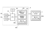
図6は、本実施形態における制御構成を示す要部ブロック図である。
図6に示すように、時計500には、時計各部の動作を制御する制御部6が設けられている。
制御部6は、CPU(Central Processing Unit)61、ROM(Read Only Memory)62、RAM(Random Access Memory)63、発振器(図6において「OSC」と記載)64及びモータ制御部65等を備えている。
制御部6の構成は、特に限定されないが、例えばLSI(Large Scale Integration;大規模集積回路)等で構成されている。
CPU61は、ROM62に記憶された制御プログラムに基づいて、モータ制御部65に対して各種コマンドを出力する。RAM63は、CPU61のワークメモリとして用いられる。また、発振器64は、図示しない振動子との組み合わせにより、固有の周波数信号を生成してCPU61等に対し動作クロックを出力する。
Next, a motor driving device that drives the stepping
As described above, the stepping
FIG. 6 is a principal block diagram showing a control configuration in the present embodiment.
As shown in FIG. 6, the
The
The configuration of the
The
モータ制御部65は、駆動パルスを生成してモータ駆動回路5に対しこの駆動パルスを出力する駆動パルス生成部651と、ロータ15が正常に回転したか否かを判定する回転検出判定部652と、第1のスイッチング部653等を備えている。
駆動パルス生成部651は、ステッピングモータ1を駆動させる際に、スイッチング素子(本実施形態では、スイッチング素子51〜58(後述)を備える第1のスイッチング部653)に駆動パルスを出力するものである。本実施形態では、駆動パルス生成部651は、コイルC1,C2,C3を駆動させるための電流の流れる経路が1つとなるように、スイッチング素子51〜58に対して駆動パルスを出力する。
駆動パルス生成部651がスイッチング素子51〜58に対して駆動パルスを出力することにより、ステッピングモータ1のステータ11におけるロータ15の外周に沿って、当該外周を3分割した位置にそれぞれ磁極(第1磁極、第2磁極及び第3磁極)を出現させるようになっている。
本実施形態では、駆動パルス生成部651は、ステッピングモータ1の3つのコイルC1,C2,C3のうちのいずれか1つを順次駆動させるように適宜スイッチング素子51〜58に対して駆動パルスを出力する。そして、これにより、ロータ15の外周に沿って現れる磁極(第1磁極、第2磁極及び第3磁極)の極性を順次切り替えるようになっている。
また、第1のスイッチング部653は、LSI等で構成される制御部6内に設けられる内部的なスイッチであるスイッチング素子51〜58を備え、コイルC1,C2,C3を駆動させるための電流の流れる経路を制御するものである。
The
When the stepping
When the
In the present embodiment, the
The
また、本実施形態のモータ駆動回路5は、3つのコイルC1,C2,C3を備えるステッピングモータ1を駆動させるブリッジ回路である。モータ駆動回路5には、駆動パルス生成部651から出力される駆動パルスにしたがって適宜スイッチング素子51〜58(後述)のON/OFFが切り替えられることで所定の経路で電流が流れるようになっている。
図9(a)から図9(f)は、本実施形態におけるモータ駆動回路5の構成例を示す回路図である。
図9(a)から図9(f)に示すように、本実施形態のモータ駆動回路5において、電圧入力端59と接地端60との間には、図示しない電源電圧Vccが印加される。そして、電圧入力端59と接地端60との間には、3つのコイルC1,C2,C3と、FET(電界効果トランジスタ)等で構成される複数のスイッチング素子51〜58(LSI等で構成される制御部6内に設けられる内部スイッチ)とが配置されている。
The
FIG. 9A to FIG. 9F are circuit diagrams showing a configuration example of the
As shown in FIGS. 9A to 9F, in the
具体的には、第2のコイルC2と接続されている接続点t1と電圧入力端59との間にスイッチング素子51が配置され、第3のコイルC3と接続されている接続点t2と電圧入力端59との間にスイッチング素子52が配置され、第1のコイルC1と接続されている接続点t3と電圧入力端59との間にスイッチング素子53が配置されている。また、3つのコイルC1,C2,C3と接続され共通化された接続点である接続点t4と電圧入力端59との間にはスイッチング素子54が配置されている。
また、接続点t1と接地端60との間にスイッチング素子55が配置され、接続点t2と接地端60との間にスイッチング素子56が配置され、接続点t3と接地端60との間にスイッチング素子57が配置され、接続点t4と接地端60との間にスイッチング素子58が配置されている。
なお、モータ駆動回路5の構成は、ここに例示したものに限定されず、適宜変更可能である。
Specifically, the switching
A switching
The configuration of the
図7は、実施形態のステッピングモータ1及びモータ駆動装置を腕時計等の時刻表示装置の指針の運針機構(輪列機構)を駆動させる駆動源として適用した場合の構成例を示した模式図である。
本実施形態のステッピングモータ1及びモータ駆動装置は、例えば、図7に示すように、アナログ表示部501を備える時刻表示装置である時計500において、指針502(図7では、時針と分針のみを示している。なお、指針は図示例に限定されない。)を運針させるための運針機構(輪列機構)503を動作させる駆動源として用いられる。
この場合、運針機構(輪列機構)503を構成する歯車にロータ15の回転支軸が連結される。これにより、ステッピングモータ1のロータ15が回転すると、運針機構503を介して指針502が指針軸504を中心にアナログ表示部501において回転する。
このように、本実施形態のステッピングモータ1を時計の運針機構を駆動させる駆動源として適用した場合には、3つのコイルC1,C2,C3のうちのいずれか1つに順次通電されるようにモータ駆動装置による制御を行う。
FIG. 7 is a schematic diagram illustrating a configuration example when the stepping
For example, as shown in FIG. 7, the stepping
In this case, the rotation support shaft of the
As described above, when the stepping
次に、本実施形態におけるステッピングモータ1及びモータ駆動装置の作用について説明する。
ステッピングモータ1を組み立てる際には、まず、ステータ11の直状部111を、張出部112,113の厚み分だけ張出部112,113よりも高さが高くなるように、潰し加工が施した上で、この直状部111に巻き線を施して第1のコイルC1を形成する。また、第1のサイドヨーク12の直状部121に巻き線を施して第2のコイルC2を形成し、第2のサイドヨーク13の直状部131に巻き線を施して第3のコイルC3を形成する。
本実施形態では、3つのコイルC1,C2,C3の巻き線数(ターン数)は同じとする。なお、コイルC1,C2,C3が形成される直状部111,121,131の材質や断面積の大きさ等によっては、コイルC1,C2,C3の巻き線数を適宜変えてもよい。
次に、ステータ11のビス孔119と第1のサイドヨーク12及び第2のサイドヨーク13のビス孔128,138との位置が合うようにして、ステータ11の張出部112の上に第1のサイドヨーク12の張出部122及び第2のサイドヨーク13の張出部132を重ね合わせる。このとき、ステータ11は、第1のサイドヨーク12及び第2のサイドヨーク13よりも低くなるが、ステータ11の直状部111には前述のように潰し加工が施されているため、3つのコイルC1,C2,C3の高さは、ほぼ面一となる(図1(b)参照)。
Next, the operation of the stepping
When assembling the stepping
In this embodiment, the number of windings (number of turns) of the three coils C1, C2, and C3 is the same. Note that the number of windings of the coils C1, C2, and C3 may be appropriately changed depending on the material of the
Next, the screw holes 119 of the
そして、ステータ11の張出部113のほぼ中央部にスペーサ4aを配置し、その上にコイル基板16を載置する。
また、第1のサイドヨーク12の張出部123にスペーサ4aよりも張出部123の厚み分だけ薄いスペーサ4bを配置し、その上にコイル基板17を載置する。同様に、第2のサイドヨーク13の張出部133にスペーサ4aよりも張出部133の厚み分だけ薄いスペーサ4bを配置し、その上にコイル基板18を載置する。これにより、コイル基板16,17,18がコイルC1,C2,C3の高さよりもわずかに高くなるとともに、3つのコイル基板16,17,18がほぼ面一となる位置に揃う(図1(b)参照)。
And the
Further, the
次に、コイル基板16の接続点t3,t4に第1のコイルC1の端子を接続し、コイル基板17の接続点t1,t4に第2のコイルC2の端子を接続し、コイル基板18の接続点t2,t4に第3のコイルC3の端子を接続する。そして、これらの接続部分に保護用の樹脂を塗布して樹脂塗布領域16a,17a,18aを形成する。
ステッピングモータ1各部の接続が完了すると、これを、支柱部材31の位置にビス孔119の位置が合うように位置を調整してメインプレート3の上にステータ11と第1のサイドヨーク12及び第2のサイドヨーク13(ステッピングモータ1)を配置し、さらにメイン基板2の基板側ビス孔219を支柱部材31及びビス孔119の位置に合せて、ステッピングモータ1の上からメイン基板2を配置する。そして、張出部112と張出部113に対応する位置にそれぞれ2か所ずつ設けられている基板側ビス孔219及びステータ11のビス孔119にビス19を挿通させてビス19の先端側がメインプレート3の支柱部材31内に固定されるまで螺入する。これにより、ステータ11と第1のサイドヨーク12及び第2のサイドヨーク13とがビス19によって共締めされるとともに、ステッピングモータ1がメインプレート3及びメイン基板2に固定される。また、ステッピングモータ1がメイン基板2に固定されることにより、各コイル基板16,17,18に接続された各コイルC1,C2,C3の端子が、メイン基板2上のコイル用端子22a〜22dと電気的に接続される。
なお、前述のように、各コイルC1,C2,C3の高さや各コイル基板16,17,18の高さがほぼ面一に揃えられていることで、ステッピングモータ1をメインプレート3及びメイン基板2に固定した際にがたつきを生じにくく、また、無駄な隙間を生じずに効率よく実装することができる。
Next, the terminal of the first coil C1 is connected to the connection points t3 and t4 of the
When the connection of each part of the stepping
As described above, the height of each of the coils C1, C2, and C3 and the height of each of the
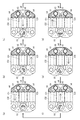
次に、図8(a)〜図8(f)及び図9(a)〜図9(f)を参照して、本実施形態におけるモータ駆動装置によるステッピングモータ1の動作制御について説明する。
図8(a)〜図8(f)は、ロータ15を正転(すなわち図8(a)等に矢印で示す時計回りの方向に回転)させる場合のロータ15の回転方向における位置及び各コイルC1,C2,C3に流れる磁束の流れ(図中矢印で示す)を示す図である。なお、ロータ受容部115の周りに示した「S」「N」は、通電状態においてロータ受容部115の周りに現れる磁極(第1の磁極、第2の磁極、第3の磁極)の極性を示している。
図9(a)〜図9(f)はそれぞれ図8(a)〜図8(f)と対応しており、図中の矢印線は、電流の流れを示している。
Next, with reference to FIG. 8A to FIG. 8F and FIG. 9A to FIG. 9F, operation control of the stepping
8 (a) to 8 (f) show the position and each coil in the rotational direction of the
9 (a) to 9 (f) correspond to FIGS. 8 (a) to 8 (f), respectively, and an arrow line in the drawing indicates a current flow.
まず、駆動パルス生成部651の制御により、モータ駆動回路5のスイッチング素子51,56,57,58をON状態とし、スイッチング素子52,53,54,55をOFF状態とする。これにより、図8(a)及び図9(a)に示すように、第2のコイルC2に電源電圧Vccが印加され、接続点t2から接続点t4に向かう方向に電流が流れる。
このとき、ステータ11には、図8(a)に示すように3つの磁極が現れ、ロータ15は、N極がステータ11側のS極と対向し、分極位置がステータ側静止部116と対向する位置で静止する。なお、これを以下「初期位置」とする。
First, under the control of the
At this time, three magnetic poles appear in the
次に、駆動パルス生成部651の制御により、モータ駆動回路5のスイッチング素子51,53,54,56をON状態とし、スイッチング素子52,55,57,58をOFF状態とする。これにより、図8(b)及び図9(b)に示すように、第3のコイルC3に電源電圧Vccが印加され、接続点t4から接続点t2に向かう方向に電流が流れる。
このとき、ステータ11には、図8(b)に示すように3つの磁極が現れ、ロータ15は、初期位置から60度時計回りに回転し、S極がステータ11側のN極と対向し、分極位置がステータ側静止部116と対向する位置で静止する。
次に、駆動パルス生成部651の制御により、モータ駆動回路5のスイッチング素子53,55,56,58をON状態とし、スイッチング素子51,52,54,57をOFF状態とする。これにより、図8(c)及び図9(c)に示すように、第1のコイルC1に電源電圧Vccが印加され、接続点t3から接続点t4に向かう方向に電流が流れる。
このとき、ステータ11には、図8(c)に示すように3つの磁極が現れ、ロータ15は、初期位置から120度時計回りに回転し、N極がステータ11側のS極と対向し、分極位置がステータ側静止部116と対向する位置で静止する。
Next, under the control of the
At this time, three magnetic poles appear in the
Next, under the control of the
At this time, three magnetic poles appear on the
次に、駆動パルス生成部651の制御により、モータ駆動回路5のスイッチング素子52,53,54,55をON状態とし、スイッチング素子51,56,57,58をOFF状態とする。これにより、図8(d)及び図9(d)に示すように、第2のコイルC2に電源電圧Vccが印加され、接続点t4から接続点t1に向かう方向に電流が流れる。
このとき、ステータ11には、図8(d)に示すように3つの磁極が現れ、ロータ15は、初期位置から180度時計回りに回転し、S極がステータ11側のN極と対向し、分極位置がステータ側静止部116と対向する位置で静止する。
次に、駆動パルス生成部651の制御により、モータ駆動回路5のスイッチング素子52,55,57,58をON状態とし、スイッチング素子51,53,54,56をOFF状態とする。これにより、図8(e)及び図9(e)に示すように、第3のコイルC3に電源電圧Vccが印加され、接続点t2から接続点t4に向かう方向に電流が流れる。
このとき、ステータ11には、図8(e)に示すように3つの磁極が現れ、ロータ15は、初期位置から240度時計回りに回転し、N極がステータ11側のS極と対向し、分極位置がステータ側静止部116と対向する位置で静止する。
Next, under the control of the
At this time, three magnetic poles appear on the
Next, under the control of the drive
At this time, three magnetic poles appear on the
さらに、駆動パルス生成部651の制御により、モータ駆動回路5のスイッチング素子51,52,54,57をON状態とし、スイッチング素子53,55,56,58をOFF状態とする。これにより、図8(f)及び図9(f)に示すように、第1のコイルC1に電源電圧Vccが印加され、接続点t4から接続点t3に向かう方向に電流が流れる。
このとき、ステータ11には、図8(f)に示すように3つの磁極が現れ、ロータ15は、初期位置から300度時計回りに回転し、S極がステータ11側のN極と対向し、分極位置がステータ側静止部116と対向する位置で静止する。
そして、再度駆動パルス生成部651の制御により、モータ駆動回路5のスイッチング素子51,56,57,58をON状態とし、スイッチング素子52,53,54,55をOFF状態とすることにより、図8(a)及び図9(a)に示す状態となり、ロータ15は、初期位置から360度回転して元の位置に戻る。
このように、本実施形態では、ロータ15を1ステップ(本実施形態では60度)ずつ回転させる場合に、駆動パルス生成部651が、コイルC1,C2,C3を駆動させるための電流の流れる経路が1つとなるように、モータ駆動回路5に対して駆動パルスを出力する。具体的には、駆動パルス生成部651は、いずれか1つのコイルC1,C2,C3のみが駆動するようにモータ駆動回路5に対して駆動パルスを出力し、順次いずれか1つのコイルC1,C2,C3が駆動されるようになっている。このため、2つ以上のコイルを並列に通電して駆動させる場合よりも一層の省電力化を実現することができる。
Further, under the control of the
At this time, three magnetic poles appear on the
Then, under the control of the
As described above, in this embodiment, when the
以上のように、本実施形態によれば、ステッピングモータ1に3つのコイルC1,C2,C3を設けるとともに、この3つのコイルC1,C2,C3のうち、少なくとも1つ(本実施形態では第1のコイルC1)はステータ11の一部に巻き線を施すことで一体的に形成された一体型コイルとしている。このため、ステッピングモータ1の構成を複雑化させたり、大型化することなく、最小の実装面積で3つのコイルC1,C2,C3を有するステッピングモータ1を実現することができ、小型の腕時計等における高密度実装にも対応することができる。
また、ステータ11は、直状部111を有しており、ステータ11に一体的に形成された一体型コイルである第1のコイルC1は、この直状部111に巻き線を施すことで形成されている。このため、専用のコイルコアに巻き線を施す場合と同様に均等に巻き線を施すことができる。
また、3つのコイルC1,C2,C3のうちの他のコイル(本実施形態では第2のコイルC2及び第3のコイルC3)は、ステータ11の張出部113に磁気的に結合されている。これにより、3つコイル全てがステッピングモータ1を構成するコイルとして動作することが可能であるとともに、組み立て前の状態ではそれぞれが別個の部材であり、各巻き線部に巻き線を施して各コイルを完成させてから一体化させることができるため、ステッピングモータ1の組み立て作業性を落とすことなく、3つのコイルC1,C2,C3を有するステッピングモータ1を実現することができる。
また、ロータ受容部115には、ロータ15の外周に沿って、ほぼ等間隔にステータ側静止部116が設けられており、ロータ15は、いずれかのステータ側静止部116と、ロータ15の分極位置とが対向する位置で静止するように構成されている.このように、ステータ側静止部116を設けることで、ロータ15を所望の位置で確実に静止させることができ、高精度のモータを実現することができる。
また、本実施形態では、ステータ11と第1のサイドヨーク12及び第2のサイドヨーク13を4つのビス19によって共締めし、メインプレート3及びメイン基板2に固定している。これにより、実装面積のロスを抑えるとともに、部品点数を減少させることによる製品コストの低減及び組み立て作業性の向上を図ることができる。
また、従来3つのコイルを駆動させるためには、各コイルについて2つずつ、6つの端子を設ける必要があり、ICチップのダウンサイジング等において難点があった。この点、本実施形態では、各コイルの片側の端子の接続点を共通として、4つの接続点を設けることで対応している。このため、実装面積を小さく抑え、効率よく高密度な実装を実現することができる。
また、60度等の細かいステップ角を実現しうるステッピングモータのロータとして異型の磁石を用いることも考えられるが、異型の磁石は時計用のモータ等に組み込むことのできる極小サイズに形成することは困難であり、手間やコストがかかるとともに、仮に形成することができたとしても、異型の磁石では形状と着磁の向きを統一させることが極めて困難であり、実現性に乏しい。この点、本実施形態では、ステッピングモータ1のロータ15として、径方向に2極着磁された円盤状の磁石を用いているため、異型の磁石を用いる場合と比べて容易に生産及びモータへの組み込みが可能である。
また、2つのコイルを有するステッピングモータの場合、3箇所のヨーク(センターヨーク及び一対のサイドヨーク)に対する各ステップにはコイルの逆起電力の影響を受けやすいステップと受けにくいステップが存在する。このため、ステップ角が不均一となりやすくロータの回転を円滑にすることが困難で、時計の指針を動作させるためのモータに適用した場合、滑らかな運針を行うことができなかった。この点、本実施形態では、3つのコイルC1,C2,C3を備え、これらを順次駆動させることでロータ15を回転させるため、ステップ角を安定させてロータ15を円滑に回転させることができ、精度のよいステッピングモータを実現することが可能となる。これにより、滑らかな運針を実現することができ、例えば秒針等をスイープ運針させる場合等において特に有効となる。
また、本実施形態では、3つのコイルC1,C2,C3の端子が接続される接続点t1〜t4のうち一部(本実施形態では接続点t4)が共通とされている。このため、配線や回路構成等を単純化することができる。
また、本実施形態では、駆動パルス生成部651は、コイルC1,C2,C3を駆動させるための電流の流れる経路が1つとなるように、適宜第1のスイッチング部653のスイッチング素子51〜58に対して駆動パルスを出力する。具体的には、ステッピングモータ1の3つのコイルC1,C2,C3のうちのいずれか1つを順次駆動させるように駆動パルスを出力する。このため、3つのコイルC1,C2,C3を備える場合でも、2つ以上の経路で電流が流れる場合と比較して、低消費電力化を図ることができる。
そして、駆動パルス生成部651は、適宜スイッチング素子51〜58に3つのコイルC1,C2,C3のうちのいずれか1つを順次駆動させるように駆動パルスを出力することでステータ11に現れる第1磁極、第2磁極及び第3磁極の極性を順次切り替えることができるようになっている。これにより、省電力化を図りつつ、正確なステップ角でロータ15を回転させ、高精度なステッピングモータ1を実現することができる。
As described above, according to the present embodiment, the stepping
Further, the
Further, the other coils (second coil C2 and third coil C3 in the present embodiment) among the three coils C1, C2, and C3 are magnetically coupled to the overhanging
Further, the
In the present embodiment, the
Conventionally, in order to drive three coils, it is necessary to provide six terminals, two for each coil, and there is a difficulty in downsizing of an IC chip. In this respect, in the present embodiment, the connection point of the terminal on one side of each coil is shared, and four connection points are provided. For this reason, a mounting area can be suppressed small and efficient and high-density mounting can be realized.
In addition, it is conceivable to use an irregular magnet as a rotor of a stepping motor that can realize a fine step angle such as 60 degrees. However, an irregular magnet can be formed into a minimum size that can be incorporated into a watch motor or the like. It is difficult, laborious and costly, and even if it can be formed, it is extremely difficult to unify the shape and the direction of magnetization with an atypical magnet, and its feasibility is poor. In this regard, in the present embodiment, since the disk-shaped magnet magnetized in the radial direction as the
In the case of a stepping motor having two coils, each step for three yokes (a center yoke and a pair of side yokes) includes a step that is susceptible to the influence of the back electromotive force of the coil and a step that is difficult to receive. For this reason, the step angle is likely to be uneven and it is difficult to smoothly rotate the rotor, and when applied to a motor for operating a timepiece hand, smooth hand movement cannot be performed. In this regard, in this embodiment, the
In the present embodiment, some of the connection points t1 to t4 to which the terminals of the three coils C1, C2, and C3 are connected (connection point t4 in the present embodiment) are common. For this reason, wiring, a circuit structure, etc. can be simplified.
Further, in the present embodiment, the
Then, the
なお、駆動パルス生成部651によるスイッチング素子51〜58への駆動パルスの出力制御は、本実施形態に例示したものに限定されない。
例えば、駆動させるコイル以外のコイルについてはハイインピーダンス状態としてもよい。
ここで、駆動させるコイル以外のコイルについてはハイインピーダンス状態とする例について、図10(a)〜図10(f)を参照しつつ説明する。なお、図10(a)〜図10(f)は、図8(a)〜図8(f)とそれぞれ対応している。
Note that the drive pulse output control to the
For example, coils other than the coil to be driven may be in a high impedance state.
Here, an example in which the coils other than the coil to be driven are in a high impedance state will be described with reference to FIGS. 10 (a) to 10 (f). 10 (a) to 10 (f) correspond to FIGS. 8 (a) to 8 (f), respectively.
まず、初期状態において、第2のコイルC2のみに通電させる場合、駆動パルス生成部651は、スイッチング素子51,56のみをON状態とし、その他のスイッチング素子をOFF状態とするように適宜第1のスイッチング部653のスイッチング素子51〜58に駆動パルスを出力し、モータ駆動回路5を制御する。これにより、図8(a)及び図10(a)に示すように、第2のコイルC2のみに電源電圧Vccが印加され、その他の第1のコイルC1及び第3のコイルC3については電流経路が断たれて(すなわち、第1のコイルC1及び第3のコイルC3が擬似的にモータ駆動回路5から切り離されて)ハイインピーダンス状態となる。
また、初期状態からロータ15を60度回転させる場合には、第3のコイルC3のみに通電させるため、駆動パルス生成部651は、スイッチング素子53,56のみをON状態とし、その他のスイッチング素子をOFF状態とするように適宜第1のスイッチング部653のスイッチング素子51〜58に駆動パルスを出力し、モータ駆動回路5を制御する。これにより、図8(b)及び図10(b)に示すように、第3のコイルC3のみに電源電圧Vccが印加され、その他の第1のコイルC1及び第2のコイルC2については電流経路が断たれて(すなわち、第1のコイルC1及び第2のコイルC2が擬似的にモータ駆動回路5から切り離されて)ハイインピーダンス状態となる。
First, when only the second coil C2 is energized in the initial state, the
In addition, when the
また、初期状態からロータ15を120度回転させる場合には、第1のコイルC1のみに通電させるため、駆動パルス生成部651は、スイッチング素子53,58のみをON状態とし、その他のスイッチング素子をOFF状態とするように適宜第1のスイッチング部653のスイッチング素子51〜58に駆動パルスを出力し、モータ駆動回路5を制御する。これにより、図8(c)及び図10(c)に示すように、第1のコイルC1のみに電源電圧Vccが印加され、その他の第2のコイルC2及び第3のコイルC3については電流経路が断たれて(すなわち、第2のコイルC2及び第3のコイルC3が擬似的にモータ駆動回路5から切り離されて)ハイインピーダンス状態となる。
また、初期状態からロータ15を180度回転させる場合には、第2のコイルC2のみに通電させるため、駆動パルス生成部651は、スイッチング素子52,55のみをON状態とし、その他のスイッチング素子をOFF状態とするように適宜第1のスイッチング部653のスイッチング素子51〜58に駆動パルスを出力し、モータ駆動回路5を制御する。これにより、図8(d)及び図10(d)に示すように、第2のコイルC2のみに電源電圧Vccが印加され、その他の第1のコイルC1及び第3のコイルC3については電流経路が断たれて(すなわち、第1のコイルC1及び第3のコイルC3が擬似的にモータ駆動回路5から切り離されて)ハイインピーダンス状態となる。
In addition, when the
Further, when the
また、初期状態からロータ15を240度回転させる場合には、第3のコイルC3のみに通電させるため、駆動パルス生成部651は、スイッチング素子52,57のみをON状態とし、その他のスイッチング素子をOFF状態とするように適宜第1のスイッチング部653のスイッチング素子51〜58に駆動パルスを出力し、モータ駆動回路5を制御する。これにより、図8(e)及び図10(e)に示すように、第3のコイルC3のみに電源電圧Vccが印加され、その他の第1のコイルC1及び第2のコイルC2については電流経路が断たれて(すなわち、第1のコイルC1及び第2のコイルC2が擬似的にモータ駆動回路5から切り離されて)ハイインピーダンス状態となる。
また、初期状態からロータ15を300度回転させる場合には、第1のコイルC1のみに通電させるため、駆動パルス生成部651は、スイッチング素子54,57のみをON状態とし、その他のスイッチング素子をOFF状態とするように適宜第1のスイッチング部653のスイッチング素子51〜58に駆動パルスを出力し、モータ駆動回路5を制御する。これにより、図8(f)及び図10(f)に示すように、第1のコイルC1のみに電源電圧Vccが印加され、その他の第2のコイルC2及び第3のコイルC3については電流経路が断たれて(すなわち、第2のコイルC2及び第3のコイルC3が擬似的にモータ駆動回路5から切り離されて)ハイインピーダンス状態となる。
Further, when the
Further, when the
このように、通常接続と状態の異なるハイインピーダンス接続とすることにより低消費電流化も可能となる。
すなわち、通電するコイル(例えば第1のコイルC1)以外のコイル(例えば第2のコイルC2及び第3のコイルC3)をハイインピーダンス状態としながら1つのコイル(例えば第1のコイルC1)を駆動することにより、駆動していないコイル(例えば第2のコイルC2及び第3のコイルC3)から発生するリアクタンスを無くすことが可能となり、低消費電流で駆動させ、低消費電力化を図ることが可能となる。
また、回転検出判定部652がロータ15の回転検出を行う場合、回転検出対象となるコイルで生じた逆起電力を回転検出判定部652において検出する。しかし、複数のコイルを備えるステッピングモータにおいては、回転検出対象となるコイルで生じた逆起電力が駆動していないかった他のコイルも含めた複数のコイル(本実施形態では3つのコイルC1,C2,C3)で分散されたり、吸収しあったりすることにより、逆起電力のピークが低くなってしまい、正確な回転検出が難しいという問題がある。この点、通電するコイル以外のコイルをハイインピーダンス状態とすることにより、逆起電力の分散や吸収をなくすことができ、回転検出判定部652による回転検出の精度を向上させることができる。
In this way, the current consumption can be reduced by making the high impedance connection different from the normal connection.
That is, one coil (for example, the first coil C1) is driven while the coils (for example, the second coil C2 and the third coil C3) other than the coil to be energized (for example, the first coil C1) are in a high impedance state. As a result, it is possible to eliminate reactance generated from the coils that are not driven (for example, the second coil C2 and the third coil C3), and it is possible to drive with low current consumption and to reduce power consumption. Become.
In addition, when the rotation
また、モータ駆動回路5の各部の接続やON/OFF切り替えの仕方は、本実施形態で示したものに限定されない。
例えば、図11(a)に示すように、初期状態において、第2のコイルC2のみに通電させる場合、駆動パルス生成部651は、スイッチング素子51,56,57,58をON状態とし、その他のスイッチング素子をOFF状態とするように適宜第1のスイッチング部653のスイッチング素子51〜58に駆動パルスを出力し、モータ駆動回路5を制御する。これにより、図8(a)及び図11(a)に示すように、第2のコイルC2のみに電源電圧Vccが印加される。
Moreover, the connection of each part of the
For example, as shown in FIG. 11 (a), when only the second coil C2 is energized in the initial state, the
また、初期状態からロータ15を60度回転させる場合には、第3のコイルC3のみに通電させるため、駆動パルス生成部651は、スイッチング素子53,54,55,56のみをON状態とし、その他のスイッチング素子をOFF状態とするように適宜第1のスイッチング部653のスイッチング素子51〜58に駆動パルスを出力し、モータ駆動回路5を制御する。これにより、図8(b)及び図11(b)に示すように、第3のコイルC3のみに電源電圧Vccが印加される。
また、初期状態からロータ15を120度回転させる場合には、第1のコイルC1のみに通電させるため、駆動パルス生成部651は、スイッチング素子51,52,53,58のみをON状態とし、その他のスイッチング素子をOFF状態とするように適宜第1のスイッチング部653のスイッチング素子51〜58に駆動パルスを出力し、モータ駆動回路5を制御する。これにより、図8(c)及び図11(c)に示すように、第1のコイルC1のみに電源電圧Vccが印加される。
また、初期状態からロータ15を180度回転させる場合には、第2のコイルC2のみに通電させるため、駆動パルス生成部651は、スイッチング素子52,53,54,55のみをON状態とし、その他のスイッチング素子をOFF状態とするように適宜第1のスイッチング部653のスイッチング素子51〜58に駆動パルスを出力し、モータ駆動回路5を制御する。これにより、図8(d)及び図11(d)に示すように、第2のコイルC2のみに電源電圧Vccが印加される。
Further, when the
Further, when the
Further, when the
また、初期状態からロータ15を240度回転させる場合には、第3のコイルC3のみに通電させるため、駆動パルス生成部651は、スイッチング素子51,52,57,58のみをON状態とし、その他のスイッチング素子をOFF状態とするように適宜第1のスイッチング部653のスイッチング素子51〜58に駆動パルスを出力し、モータ駆動回路5を制御する。これにより、図8(e)及び図11(e)に示すように、第3のコイルC3のみに電源電圧Vccが印加される。
また、初期状態からロータ15を300度回転させる場合には、第1のコイルC1のみに通電させるため、駆動パルス生成部651は、スイッチング素子54,55,56,57のみをON状態とし、その他のスイッチング素子をOFF状態とするように適宜第1のスイッチング部653のスイッチング素子51〜58に駆動パルスを出力し、モータ駆動回路5を制御する。これにより、図8(f)及び図11(f)に示すように、第1のコイルC1のみに電源電圧Vccが印加される。
Further, when the
Further, when the
このように、配線の仕方やON/OFF切り替えの仕方を適宜変えることによっても、本実施形態と同様に、コイルC1,C2,C3を駆動させるための電流の流れる経路が1つとなるように、適宜第1のスイッチング部653のスイッチング素子51〜58に対して駆動パルスを出力し、3つのコイルC1,C2,C3のうちのいずれか1つを順次駆動させることができる。
これにより、ステッピングモータ1を駆動させる際のエネルギーを抑え、低消費電力化を図ることができる。
As described above, also by appropriately changing the wiring method and the ON / OFF switching method, the current flow for driving the coils C1, C2, and C3 becomes one as in the present embodiment. A drive pulse is output to the
Thereby, the energy at the time of driving the stepping
[第2の実施形態]
次に、図12(a)〜図12(f)から図14を参照しつつ、本発明に係るステッピングモータ及びモータ駆動装置の第2の実施形態について説明する。なお、本実施形態は、コイルの接続の仕方及びその動作制御のみが第1の実施形態と異なるものであるため、以下においては、特に第1の実施形態と異なる点について説明する。
なお、本実施形態のステッピングモータ及びモータ駆動装置を時計等の時刻表示装置に適用した場合の構成は第1の実施形態と同様であることからその説明を省略する。
[Second Embodiment]
Next, a second embodiment of the stepping motor and motor drive device according to the present invention will be described with reference to FIGS. 12 (a) to 12 (f) to FIG. Note that this embodiment is different from the first embodiment only in the way of connecting the coils and the operation control thereof, and therefore, the points that are different from the first embodiment will be described below.
In addition, since the structure at the time of applying the stepping motor and motor drive apparatus of this embodiment to time display apparatuses, such as a timepiece, is the same as that of 1st Embodiment, the description is abbreviate | omitted.
本実施形態において、ステッピングモータ1は第1の実施形態と同様に3つのコイルC1,C2,C3を備えている。
図12(a)〜図12(f)は、ステッピングモータ1のロータ15を1ステップ60度ずつ回転させる場合においてコイルC1,C2,C3に流れる磁束の流れを示したものであり、矢印線は各コイルC1,C2,C3に流れる磁束の向きを示している。
図13(a)〜図13(f)は、モータ駆動回路5を示す回路図であり、図13(a)〜図13(f)はそれぞれ図12(a)〜図12(f)の各状態に対応している。
また、図14は、本実施形態における制御構成を示す要部ブロック図である。
In the present embodiment, the stepping
12 (a) to 12 (f) show the flow of magnetic flux flowing through the coils C1, C2, and C3 when the
13 (a) to 13 (f) are circuit diagrams showing the
FIG. 14 is a principal block diagram showing a control configuration in the present embodiment.
本実施形態において、図13(a)〜図13(f)に示すように、3つのコイルC1,C2,C3は、直列に接続されている。
また、図14に示すように、本実施形態では、第1の実施形態と同様に、LSI等で構成される制御部6内に設けられる内部的なスイッチであるスイッチング素子51〜58を有する第1のスイッチング部653を備える他、直列に接続された第1のコイルC1、第2のコイルC2、第3のコイルC3の間のON/OFF状態を切り替えるスイッチング素子61〜64を有する第2のスイッチング部654を備えている。ここで、スイッチング素子61〜64は、メイン基板2上等に設けられる外部的なスイッチである。
なお、このように、本実施形態では、外部スイッチとして設けられるスイッチング素子61〜64を備えているため、第1の実施形態と異なり、図12(a)〜図12(f)に示すように、電気的、磁気的、機能的接続点であるt1,t2,t3,t4とステッピングモータ1上の物理的なパッドとの対応関係が適宜変化する。
In this embodiment, as shown to Fig.13 (a)-FIG.13 (f), the three coils C1, C2, and C3 are connected in series.
As shown in FIG. 14, in the present embodiment, as in the first embodiment, the switching
As described above, in the present embodiment, since the switching
駆動パルス生成部651は、3つのコイルC1,C2,C3を同時駆動させる駆動パルスを生成し、スイッチング素子51〜58(スイッチング素子51〜58を有する第1のスイッチング部653)及びスイッチング素子61〜64(スイッチング素子61〜64を有する第2のスイッチング部654)に出力する。なお、この場合にも、第1の実施形態と同様に、コイルC1,C2,C3を駆動させるための電流の流れる経路は1つとなるように、適宜スイッチング素子51〜58を有する第1のスイッチング部653及びスイッチング素子61〜64を有する第2のスイッチング部654に対して駆動パルスを出力する。第1のスイッチング部653及び第2のスイッチング部654は、駆動パルスに従い、適宜各スイッチング素子51〜58,61〜64のON/OFF状態の切り替えを行う。
The drive
なお、その他の構成は、第1の実施形態と同様であることから、同一部材には同一の符号を付して、その説明を省略する。 In addition, since the other structure is the same as that of 1st Embodiment, the same code | symbol is attached | subjected to the same member and the description is abbreviate | omitted.
次に、本実施形態におけるステッピングモータ1及びモータ駆動装置の作用について説明する。
まず、初期状態である図12(a)においては、図13(a)に示すように、駆動パルス生成部651は、スイッチング素子51,57,61,64をON状態とし、その他のスイッチング素子をOFF状態とするように第1のスイッチング部653及び第2のスイッチング部654を制御する。これにより、モータ駆動回路5に流れる電流経路は1つであるが、3つのコイルC1,C2,C3全てが同時に駆動し、各コイルC1,C2,C3には図12(a)に示すような磁束の流れが生じる。
Next, the operation of the stepping
First, in FIG. 12A, which is the initial state, as shown in FIG. 13A, the
また、初期状態からロータ15を60度回転させる場合には、図13(b)に示すように、駆動パルス生成部651は、スイッチング素子54,56,62,63をON状態とし、その他のスイッチング素子をOFF状態とするように第1のスイッチング部653及び第2のスイッチング部654を制御する。これにより、モータ駆動回路5に流れる電流経路は1つであるが、3つのコイルC1,C2,C3全てが同時に駆動し、各コイルC1,C2,C3には図12(b)に示すような磁束の流れが生じる。そして、ロータ15の周囲に現れる3つの磁極が切り換えられ、ロータ15が初期状態から60度回転する。
また、初期状態からロータ15を120度回転させる場合には、図13(c)に示すように、駆動パルス生成部651は、スイッチング素子54,55,61,63をON状態とし、その他のスイッチング素子をOFF状態とするように第1のスイッチング部653及び第2のスイッチング部654を制御する。これにより、モータ駆動回路5に流れる電流経路は1つであるが、3つのコイルC1,C2,C3全てが同時に駆動し、各コイルC1,C2,C3には図12(c)に示すような磁束の流れが生じる。そして、ロータ15の周囲に現れる3つの磁極が切り換えられ、ロータ15が初期状態から120度回転する。
When the
When the
また、初期状態からロータ15を180度回転させる場合には、図13(d)に示すように、駆動パルス生成部651は、スイッチング素子53,55,61,64をON状態とし、その他のスイッチング素子をOFF状態とするように第1のスイッチング部653及び第2のスイッチング部654を制御する。これにより、モータ駆動回路5に流れる電流経路は1つであるが、3つのコイルC1,C2,C3全てが同時に駆動し、各コイルC1,C2,C3には図12(d)に示すような磁束の流れが生じる。そして、ロータ15の周囲に現れる3つの磁極が切り換えられ、ロータ15が初期状態から180度回転する。
また、初期状態からロータ15を240度回転させる場合には、図13(e)に示すように、駆動パルス生成部651は、スイッチング素子52,58,62,63をON状態とし、その他のスイッチング素子をOFF状態とするように第1のスイッチング部653及び第2のスイッチング部654を制御する。これにより、モータ駆動回路5に流れる電流経路は1つであるが、3つのコイルC1,C2,C3全てが同時に駆動し、各コイルC1,C2,C3には図12(e)に示すような磁束の流れが生じる。そして、ロータ15の周囲に現れる3つの磁極がさらに切り換えられ、ロータ15が初期状態から240度回転する。
When the
When the
さらに、初期状態からロータ15を300度回転させる場合には、図13(f)に示すように、駆動パルス生成部651は、スイッチング素子51,58,61,63をON状態とし、その他のスイッチング素子をOFF状態とするように第1のスイッチング部653及び第2のスイッチング部654を制御する。これにより、モータ駆動回路5に流れる電流経路は1つであるが、3つのコイルC1,C2,C3全てが同時に駆動し、各コイルC1,C2,C3には図12(f)に示すような磁束の流れが生じる。そして、ロータ15の周囲に現れる3つの磁極が切り換えられ、ロータ15が初期状態から60度回転する。
このように、電流の向きを変えながら全てのコイルC1,C2,C3を同時起動させることで、1つずつコイルを駆動させる場合と比較してさらなる低消費電力化を図ることができる。
Further, when the
In this way, by simultaneously starting all the coils C1, C2, and C3 while changing the direction of the current, it is possible to further reduce power consumption as compared with the case where the coils are driven one by one.
なお、その他の点については、第1の実施形態と同様であることから、その説明を省略する。 Since other points are the same as those in the first embodiment, description thereof is omitted.
以上のように、本実施形態によれば、第1の実施形態と同様の効果を得られる他、以下の効果を得ることができる。
すなわち、本実施形態では、ステッピングモータ1の3つのコイルC1,C2,C3を直列に接続し、全てのコイルC1,C2,C3を同時起動させるようになっている。
この場合、コイルC1,C2,C3の抵抗値は3倍となる。このため、駆動パルス生成部651からモータ駆動回路5に対して同じパルス幅の駆動パルスが入力された場合、消費電流は1つずつコイルを駆動させる場合と比較して1/3となり、かつコイルC1,C2,C3自体に発生する磁束は3倍となる。このため、並列にコイルを接続して、1つずつコイルを駆動させる場合と比較してエネルギー効率が大きく向上する。
このため、同じ消費電流でより大きな出力を得ることが可能となる。また、同じ出力を得るためのコイルの巻き線数を少なくすることも可能であり、この場合にはステッピングモータ1のさらなる小型化を図ることができる。
また、回転検出判定部652においてロータ15の回転検出を行う場合において、本実施形態のように3つのコイルC1,C2,C3を直列に接続した場合には、逆起電力のピークが高くなり、回転検出精度を向上させることも期待できる。
As described above, according to the present embodiment, the following effects can be obtained in addition to the same effects as those of the first embodiment.
That is, in this embodiment, the three coils C1, C2, and C3 of the stepping
In this case, the resistance values of the coils C1, C2, and C3 are tripled. Therefore, when a drive pulse having the same pulse width is input from the
For this reason, a larger output can be obtained with the same current consumption. It is also possible to reduce the number of coil windings for obtaining the same output, and in this case, the stepping
In addition, when the rotation
なお、以上本発明の実施形態について説明したが、本発明は、かかる実施形態に限定されず、その要旨を逸脱しない範囲で、種々変形が可能であることは言うまでもない。 Although the embodiments of the present invention have been described above, the present invention is not limited to such embodiments, and various modifications can be made without departing from the scope of the present invention.
例えば、上記各実施形態では、ステータ11をパーマロイCで形成し、第1のサイドヨーク12及び第2のサイドヨーク13はこのパーマロイCよりも飽和磁束密度の高いパーマロイBで形成する場合を例示したが、ステータ11及び第1のサイドヨーク12、第2のサイドヨーク13を形成する材料は高透磁率材料であればよく、ここに例示したものに限定されない。
例えば、ステータ11及び第1のサイドヨーク12、第2のサイドヨーク13を全てパーマロイCで形成してもよいし、これらすべてをパーマロイBで形成してもよい。
また、これらのいずれか又は全てを純鉄等で形成していてもよい。
なお、ステータ11及び第1のサイドヨーク12、第2のサイドヨーク13を全て同じ材料で形成する場合には、飽和磁束密度の違い等を考慮する必要がない。このため、ステータ11の直状部111の断面積を、第1のサイドヨーク12及び第2のサイドヨーク13の直状部121,131の断面積よりも大きくする等の調整を行う必要がなく、設計及び製造の効率を向上させることができる。
For example, in each of the above embodiments, the
For example, the
Any or all of these may be formed of pure iron or the like.
When the
また、上記各実施形態では、ステッピングモータ1が、センターヨークを構成するステータ11と、2つのサイドヨーク(すなわち、第1のサイドヨーク12及び第2のサイドヨーク13)とを磁気的に結合させることで構成されている場合を例示したが、ステータ11及びサイドヨークの構成はこれに限定されない。
例えば、上記のように、ステッピングモータのセンターヨークを構成するステータ11と、2つのサイドヨークとを全て同じ材料で形成する場合には、これらを一体の部材として形成し、それぞれの直状部の間を通しながら巻き線を施して3つのコイルC1,C2,C3を構成してもよい。
このように、センターヨークを構成するステータ11と、2つのサイドヨークとを物質的に一体に形成した場合には、部材同士の接続部分がなくなる。これにより、接続部分の空気層における損失(ロス)をなくすることができ、ステッピングモータにおいて、より効率的で低消費電流での駆動を実現し、さらなる省電力化を図ることができる。
In each of the above embodiments, the stepping
For example, as described above, when the
As described above, when the
また、第1の実施形態では1つのコイルのみを駆動させる場合を例示し、第2の実施形態では、3つのコイルを直列で接続して3つ同時に駆動させる場合を例示したが、コイルの駆動のさせ方はこれに限定されない。
例えば、3つのコイルC1,C2,C3を備える場合に、これらのうちのいずれか2つ(例えば第1のコイルC1と第2のコイルC2)を同時に駆動させるようにしてもよい。
この場合には、ステータ11に現れる磁極が2つとなり、3つ目は極性のない無極の状態となり、ロータ15の静止する向きが30度ずれることとなる。このため、ロータ15を安定的に停止させるためには、ステータ側静止部116も図1(a)等に示したものからそれぞれ30度ずつずれた位置に配置することが好ましい。
In the first embodiment, only one coil is driven. In the second embodiment, three coils are connected in series and three are driven simultaneously. The method of making is not limited to this.
For example, when three coils C1, C2, and C3 are provided, any two of them (for example, the first coil C1 and the second coil C2) may be driven simultaneously.
In this case, there are two magnetic poles appearing on the
また、上記各実施形態におけるステータ側静止部116は、ロータ15の静止状態を維持するための十分なインデックストルク(保持トルク)を得られるものであればよく、その形状等は、各実施形態において例示したものに限定されない。さらに、ロータ15側にも凹部等の静止部を形成してもよい。
Further, the stator side
また、上記各実施形態では、ステッピングモータ1及びモータ駆動措置が時計500等の時刻表示装置の指針の運針機構を駆動させるものである場合を例として説明しているが、ステッピングモータ1及びモータ駆動措置は時計の運針機構を駆動させるものに限定されない。
例えば、その他指針等を備える時刻表示装置にステッピングモータ1及びモータ駆動措置を適用してもよい。
また、ステッピングモータ1及びモータ駆動措置は時刻表示装置に適用されるものに限定されず、所定のステップ角で駆動するモータによって駆動する各種機器の駆動源として適用することが可能である。
In each of the above embodiments, the case where the stepping
For example, the stepping
Further, the stepping
その他、本発明が上記各実施形態に限定されず、適宜変更可能であることはいうまでもない。 In addition, it cannot be overemphasized that this invention is not limited to said each embodiment, and can be changed suitably.
以上本発明のいくつかの実施形態を説明したが、本発明の範囲は、上述の実施形態に限定するものではなく、特許請求の範囲に記載された発明の範囲とその均等の範囲を含む。
以下に、この出願の願書に最初に添付した特許請求の範囲に記載した発明を付記する。付記に記載した請求項の項番は、この出願の願書に最初に添付した特許請求の範囲の通りである。
〔付記〕
<請求項1>
径方向に2極着磁されたロータと、
前記ロータを受容するロータ受容部を有するステータと、
前記ステータと磁気的に結合して設けられた3つのコイルと、
を備え、
前記3つのコイルのうち、少なくとも1つは前記ステータの一部に巻き線を施すことで一体的に形成された一体型コイルであることを特徴とするステッピングモータ。
<請求項2>
前記ステータは、直状部と、この直状部の一端側から前記直状部の延在方向と直交する方向に張り出す張出部と、を有し、
前記一体型コイルは、前記直状部に巻き線を施すことで形成されており、
前記3つのコイルのうちの他のコイルは、前記ステータの前記張出部に磁気的に結合されていることを特徴とする請求項1に記載のステッピングモータ。
<請求項3>
前記ロータ受容部には、前記ロータの外周に沿って、ほぼ等間隔にステータ側静止部が設けられており、
前記ロータは、いずれかの前記ステータ側静止部と、前記ロータの分極位置とが対向する位置で静止するように構成されている請求項1又は請求項2に記載のステッピングモータ。
<請求項4>
前記3つのコイルの端子が接続される接続点のうち一部が共通していることを特徴とする請求項1から請求項3のいずれか一項に記載のステッピングモータ。
<請求項5>
前記3つのコイルは直列に接続されていることを特徴とする請求項1から請求項4のいずれか一項に記載のステッピングモータ。
<請求項6>
3つのコイルを備えるステッピングモータを駆動させるモータ駆動回路と、
前記コイルを駆動させるための電流の流れる経路を制御するためのスイッチング素子と、
前記スイッチング素子に駆動パルスを出力する駆動パルス生成部と、
を備え、
前記駆動パルス生成部は、前記コイルを駆動させるための電流の流れる経路が1つとなるように、前記スイッチング素子に対して前記駆動パルスを出力することを特徴とするモータ駆動装置。
<請求項7>
前記駆動パルス生成部は、前記スイッチング素子に前記駆動パルスを出力することで前記ステッピングモータのステータにおけるロータの外周に沿って、当該外周を3分割した位置にそれぞれ第1磁極、第2磁極及び第3磁極を出現させるとともに、前記3つのコイルのうちのいずれか1つを順次駆動させるように前記駆動パルスを出力することにより、前記第1磁極、前記第2磁極及び前記第3磁極の極性を順次切り替えることを特徴とする請求項6に記載のモータ駆動装置。
<請求項8>
前記駆動パルス生成部は、前記3つのコイルのうち、駆動させないコイルをハイインピーダンス状態とするように前記スイッチング素子に前記駆動パルスを出力することを特徴とする請求項7に記載のモータ駆動装置。
<請求項9>
請求項1から請求項5のいずれか一項に記載のステッピングモータを備えることを特徴とする時刻表示装置。
<請求項10>
請求項6から請求項8のいずれか一項に記載のモータ駆動装置を備えることを特徴とする時刻表示装置。
Although several embodiments of the present invention have been described above, the scope of the present invention is not limited to the above-described embodiments, but includes the scope of the invention described in the claims and equivalents thereof.
The invention described in the scope of claims attached to the application of this application will be added below. The item numbers of the claims described in the appendix are as set forth in the claims attached to the application of this application.
[Appendix]
<Claim 1>
A rotor with two poles in the radial direction;
A stator having a rotor receiving portion for receiving the rotor;
Three coils provided magnetically coupled to the stator;
With
At least one of the three coils is an integral coil integrally formed by winding a part of the stator.
<Claim 2>
The stator has a straight portion, and an overhang portion that projects from one end side of the straight portion in a direction perpendicular to the extending direction of the straight portion,
The integrated coil is formed by winding the straight portion,
2. The stepping motor according to
<Claim 3>
The rotor receiving portion is provided with stator-side stationary portions at substantially equal intervals along the outer periphery of the rotor,
The stepping motor according to
<Claim 4>
The stepping motor according to any one of
<Claim 5>
The stepping motor according to any one of
<Claim 6>
A motor drive circuit for driving a stepping motor having three coils;
A switching element for controlling a current flow path for driving the coil;
A drive pulse generator for outputting a drive pulse to the switching element;
With
The motor drive device, wherein the drive pulse generation unit outputs the drive pulse to the switching element so that there is a single current path for driving the coil.
<Claim 7>
The drive pulse generation unit outputs the drive pulse to the switching element, thereby forming a first magnetic pole, a second magnetic pole, and a second magnetic pole at positions where the outer periphery is divided into three along the outer periphery of the rotor in the stator of the stepping motor. By causing the three magnetic poles to appear and outputting the driving pulse so as to sequentially drive any one of the three coils, the polarities of the first magnetic pole, the second magnetic pole, and the third magnetic pole are changed. The motor driving device according to
<Claim 8>
The motor drive device according to claim 7, wherein the drive pulse generation unit outputs the drive pulse to the switching element so that a coil that is not driven among the three coils is in a high impedance state.
<Claim 9>
A time display device comprising the stepping motor according to any one of
<Claim 10>
A time display device comprising the motor drive device according to any one of
1 ステッピングモータ
5 モータ駆動回路
11 ステータ
12 第1のサイドヨーク
13 第2のサイドヨーク
15 ロータ
500 時計
651 駆動パルス生成部
C1 第1のコイル
C2 第2のコイル
C3 第3のコイル
DESCRIPTION OF
Claims (10)
第1部材で形成され、前記ロータを受容するロータ受容部を有するステータと、
前記第1部材とは異なる第2部材で形成され、前記ステータを挟んでほぼ左右対称位置に配置されるヨークと、
前記ステータと磁気的に結合して設けられた3つのコイルと、
を備え、
前記3つのコイルのうち、少なくとも1つは前記ステータの一部に巻き線を施すことで一体的に形成された一体型コイルであり、前記3つのコイルのうちの前記一体型コイル以外のコイルは前記ヨークの一部に巻き線を施すことで形成されたコイルであることを特徴とするステッピングモータ。 A rotor with two poles in the radial direction;
A stator formed of a first member and having a rotor receiving portion for receiving the rotor;
A yoke formed of a second member different from the first member, and disposed in a substantially bilaterally symmetric position across the stator;
Three coils provided magnetically coupled to the stator;
With
Wherein of the three coils, at least one Ri Ah with integrated coil integrally formed by performing winding in a part of the stator, said three of the integrated coil other than the coil of the coil a stepping motor, characterized in Oh Rukoto with coils formed by applying winding in a part of the yoke.
前記一体型コイルは、前記直状部に巻き線を施すことで形成されており、
前記3つのコイルのうちの他のコイルは、前記ステータの前記張出部に磁気的に結合されていることを特徴とする請求項1に記載のステッピングモータ。 The stator has a straight portion, and an overhang portion that projects from one end side of the straight portion in a direction perpendicular to the extending direction of the straight portion,
The integrated coil is formed by winding the straight portion,
2. The stepping motor according to claim 1, wherein another coil of the three coils is magnetically coupled to the projecting portion of the stator.
前記ロータは、いずれかの前記ステータ側静止部と、前記ロータの分極位置とが対向する位置で静止するように構成されている請求項1又は請求項2に記載のステッピングモータ。 The rotor receiving portion is provided with stator-side stationary portions at substantially equal intervals along the outer periphery of the rotor,
The stepping motor according to claim 1, wherein the rotor is configured to be stationary at a position where any one of the stator side stationary portions and a polarization position of the rotor are opposed to each other.
前記コイルを駆動させるための電流の流れる経路を制御するためのスイッチング素子と、
前記スイッチング素子に駆動パルスを出力する駆動パルス生成部と、
を備え、
前記駆動パルス生成部は、前記コイルを駆動させるための電流の流れる経路が1つとなるように、前記スイッチング素子に対して前記駆動パルスを出力することを特徴とするモータ駆動装置。 A motor drive circuit for driving a stepping motor having three coils;
A switching element for controlling a current flow path for driving the coil;
A drive pulse generator for outputting a drive pulse to the switching element;
With
The motor drive device, wherein the drive pulse generation unit outputs the drive pulse to the switching element so that there is a single current path for driving the coil.
Priority Applications (5)
| Application Number | Priority Date | Filing Date | Title |
|---|---|---|---|
| JP2016061165A JP6414115B2 (en) | 2016-03-25 | 2016-03-25 | Stepping motor, motor drive device, and time display device |
| US15/391,704 US10511248B2 (en) | 2016-03-25 | 2016-12-27 | Stepping motor, motor drive device and time display device |
| CN201710142013.6A CN107231075B (en) | 2016-03-25 | 2017-03-10 | Stepper motor, motor drive and display device |
| EP17162406.7A EP3223414B1 (en) | 2016-03-25 | 2017-03-22 | Stepping motor, motor drive device and time display device |
| US15/881,284 US10637385B2 (en) | 2016-03-25 | 2018-01-26 | Stepping motor, motor drive device and time display device |
Applications Claiming Priority (1)
| Application Number | Priority Date | Filing Date | Title |
|---|---|---|---|
| JP2016061165A JP6414115B2 (en) | 2016-03-25 | 2016-03-25 | Stepping motor, motor drive device, and time display device |
Publications (3)
| Publication Number | Publication Date |
|---|---|
| JP2017175822A JP2017175822A (en) | 2017-09-28 |
| JP2017175822A5 JP2017175822A5 (en) | 2017-11-24 |
| JP6414115B2 true JP6414115B2 (en) | 2018-10-31 |
Family
ID=58401502
Family Applications (1)
| Application Number | Title | Priority Date | Filing Date |
|---|---|---|---|
| JP2016061165A Active JP6414115B2 (en) | 2016-03-25 | 2016-03-25 | Stepping motor, motor drive device, and time display device |
Country Status (4)
| Country | Link |
|---|---|
| US (2) | US10511248B2 (en) |
| EP (1) | EP3223414B1 (en) |
| JP (1) | JP6414115B2 (en) |
| CN (1) | CN107231075B (en) |
Families Citing this family (4)
| Publication number | Priority date | Publication date | Assignee | Title |
|---|---|---|---|---|
| JP2019047559A (en) * | 2017-08-30 | 2019-03-22 | カシオ計算機株式会社 | Rotation control device, electronic clock and rotation control method |
| JP7081268B2 (en) * | 2018-03-29 | 2022-06-07 | セイコーエプソン株式会社 | Motor control circuit, movement, electronic clock |
| JP7073849B2 (en) * | 2018-03-29 | 2022-05-24 | セイコーエプソン株式会社 | Motor control circuit, movement, electronic clock |
| JP7290527B2 (en) * | 2019-09-24 | 2023-06-13 | セイコーインスツル株式会社 | Stepping motor controller, clock and stepping motor control method |
Family Cites Families (22)
| Publication number | Priority date | Publication date | Assignee | Title |
|---|---|---|---|---|
| JPS53132380A (en) | 1977-04-23 | 1978-11-18 | Seiko Instr & Electronics Ltd | Electronic watch |
| FR2529032A1 (en) * | 1982-06-21 | 1983-12-23 | Omega Brandt & Freres Sa Louis | PROCESS FOR SUPPLYING A STEP-BY-STEP MOTOR FOR A WATCHING PART |
| JP2698801B2 (en) * | 1994-07-28 | 1998-01-19 | セイコープレシジョン株式会社 | Rotating magnetic field type motor |
| JPH0847726A (en) | 1994-08-05 | 1996-02-20 | Daihatsu Motor Co Ltd | Biaxial cross type rotary cam |
| JP2881160B2 (en) * | 1994-12-27 | 1999-04-12 | セイコープレシジョン株式会社 | Rotating magnetic field type motor |
| JP2733824B2 (en) * | 1995-04-19 | 1998-03-30 | 日本サーボ株式会社 | Two-phase permanent magnet rotating electric machine |
| JP2852339B2 (en) * | 1995-07-13 | 1999-02-03 | セイコープレシジョン株式会社 | Step motor drive control device |
| JP3541601B2 (en) | 1997-02-07 | 2004-07-14 | セイコーエプソン株式会社 | Control device for stepping motor, control method thereof, and timing device |
| JP2000069796A (en) | 1998-06-10 | 2000-03-03 | Asmo Co Ltd | Stepping motor drive circuit and apparatus for driving the same |
| CN100495872C (en) * | 2003-06-30 | 2009-06-03 | 精工精密株式会社 | Step motor |
| JP4620590B2 (en) * | 2003-08-29 | 2011-01-26 | セイコープレシジョン株式会社 | Electromagnetic actuator |
| JP4007339B2 (en) | 2003-11-07 | 2007-11-14 | 株式会社デンソー | AC motor and its control device |
| US7050311B2 (en) * | 2003-11-25 | 2006-05-23 | Electric Power Research Institute, Inc. | Multilevel converter based intelligent universal transformer |
| KR100688206B1 (en) * | 2005-03-08 | 2007-03-02 | 엘지전자 주식회사 | Motor |
| KR100663641B1 (en) | 2006-04-06 | 2007-01-05 | 주식회사 아모텍 | Method for making integrated stator, brushless direct current motor of radial core type having a structure of double rotors and method for making the same using the method |
| JP5827026B2 (en) * | 2011-04-07 | 2015-12-02 | トヨタ自動車株式会社 | Rotating electric machine and rotating electric machine drive system |
| JP2012222941A (en) * | 2011-04-07 | 2012-11-12 | Toyota Motor Corp | Rotating electric machine |
| JP6303277B2 (en) | 2013-03-29 | 2018-04-04 | カシオ計算機株式会社 | Stepping motor and clock |
| JP2015061467A (en) * | 2013-09-20 | 2015-03-30 | カシオ計算機株式会社 | Stepping motor and clock |
| JP6515454B2 (en) * | 2013-09-20 | 2019-05-22 | カシオ計算機株式会社 | Stepper motor and watch |
| HUE037882T2 (en) | 2014-09-19 | 2018-09-28 | Siemens Ag | Electric machine with low magnetic groove scattering |
| JP6772500B2 (en) * | 2016-03-22 | 2020-10-21 | カシオ計算機株式会社 | Rotation detector and electronic clock |
-
2016
- 2016-03-25 JP JP2016061165A patent/JP6414115B2/en active Active
- 2016-12-27 US US15/391,704 patent/US10511248B2/en active Active
-
2017
- 2017-03-10 CN CN201710142013.6A patent/CN107231075B/en active Active
- 2017-03-22 EP EP17162406.7A patent/EP3223414B1/en active Active
-
2018
- 2018-01-26 US US15/881,284 patent/US10637385B2/en active Active
Also Published As
| Publication number | Publication date |
|---|---|
| US20170279395A1 (en) | 2017-09-28 |
| JP2017175822A (en) | 2017-09-28 |
| CN107231075A (en) | 2017-10-03 |
| EP3223414B1 (en) | 2023-07-12 |
| EP3223414A3 (en) | 2018-03-07 |
| CN107231075B (en) | 2019-11-05 |
| US10511248B2 (en) | 2019-12-17 |
| US10637385B2 (en) | 2020-04-28 |
| EP3223414A2 (en) | 2017-09-27 |
| US20180152129A1 (en) | 2018-05-31 |
Similar Documents
| Publication | Publication Date | Title |
|---|---|---|
| JP6414115B2 (en) | Stepping motor, motor drive device, and time display device | |
| US9537435B2 (en) | Stepping motor and timepiece provided with stepping motor | |
| US20150084573A1 (en) | Stepping motor and timepiece provided with stepping motor | |
| CN106452233B (en) | Motor driving device and electronic timepiece | |
| JP6303277B2 (en) | Stepping motor and clock | |
| JPH0919117A (en) | Multipolar motor with two rotors | |
| US20120170426A1 (en) | Analogue electronic timepiece | |
| JP6380116B2 (en) | Hand movement mechanism and clock | |
| JP6349662B2 (en) | Stepping motor and clock | |
| US10539927B2 (en) | Timepiece, electronic device, and control method of timepiece | |
| JP5086116B2 (en) | Step motor for watch | |
| JP2018057076A (en) | Stepping motor, rotation detection device, and electronic clock | |
| JP2009081986A (en) | Stepping motor | |
| JP6312078B2 (en) | Step motor, step motor drive control method, timepiece movement, and timepiece | |
| JPS58190271A (en) | Reversible stepping motor | |
| JP2012018080A (en) | Step motor and step motor device using the same | |
| JP6433328B2 (en) | Stepping motor | |
| JP2003248069A (en) | Stepping motor and electronic clock | |
| JP2002238233A (en) | Spindle motor and its rotational index regulating method | |
| JP2013057633A (en) | Analog electronic chronometer | |
| JP2002277565A (en) | Step motor for timepiece | |
| JPH10290559A (en) | Stepping motor, time measuring apparatus and electronic apparatus | |
| JP2003185765A (en) | Stepping motor and electronic timepiece | |
| JP2006071540A (en) | Electronic timepiece provided with contactless switch | |
| JP2003070221A (en) | Head actuator and magnetic recording/reproducing device |
Legal Events
| Date | Code | Title | Description |
|---|---|---|---|
| A521 | Request for written amendment filed |
Free format text: JAPANESE INTERMEDIATE CODE: A523 Effective date: 20171010 |
|
| A621 | Written request for application examination |
Free format text: JAPANESE INTERMEDIATE CODE: A621 Effective date: 20171010 |
|
| A977 | Report on retrieval |
Free format text: JAPANESE INTERMEDIATE CODE: A971007 Effective date: 20180622 |
|
| A131 | Notification of reasons for refusal |
Free format text: JAPANESE INTERMEDIATE CODE: A131 Effective date: 20180703 |
|
| A521 | Request for written amendment filed |
Free format text: JAPANESE INTERMEDIATE CODE: A523 Effective date: 20180830 |
|
| TRDD | Decision of grant or rejection written | ||
| A01 | Written decision to grant a patent or to grant a registration (utility model) |
Free format text: JAPANESE INTERMEDIATE CODE: A01 Effective date: 20180904 |
|
| A61 | First payment of annual fees (during grant procedure) |
Free format text: JAPANESE INTERMEDIATE CODE: A61 Effective date: 20180917 |
|
| R150 | Certificate of patent or registration of utility model |
Ref document number: 6414115 Country of ref document: JP Free format text: JAPANESE INTERMEDIATE CODE: R150 |