EP3223414B1 - Stepping motor, motor drive device and time display device - Google Patents
Stepping motor, motor drive device and time display device Download PDFInfo
- Publication number
- EP3223414B1 EP3223414B1 EP17162406.7A EP17162406A EP3223414B1 EP 3223414 B1 EP3223414 B1 EP 3223414B1 EP 17162406 A EP17162406 A EP 17162406A EP 3223414 B1 EP3223414 B1 EP 3223414B1
- Authority
- EP
- European Patent Office
- Prior art keywords
- coil
- side yoke
- stator
- projecting part
- rotor
- Prior art date
- Legal status (The legal status is an assumption and is not a legal conclusion. Google has not performed a legal analysis and makes no representation as to the accuracy of the status listed.)
- Active
Links
- 238000004804 winding Methods 0.000 claims description 27
- 239000000758 substrate Substances 0.000 description 79
- 230000004907 flux Effects 0.000 description 38
- 125000006850 spacer group Chemical group 0.000 description 27
- 230000007246 mechanism Effects 0.000 description 14
- 229910000889 permalloy Inorganic materials 0.000 description 14
- 238000001514 detection method Methods 0.000 description 12
- 230000004048 modification Effects 0.000 description 12
- 238000012986 modification Methods 0.000 description 12
- 239000000463 material Substances 0.000 description 9
- 230000035699 permeability Effects 0.000 description 7
- 239000011347 resin Substances 0.000 description 7
- 229920005989 resin Polymers 0.000 description 7
- 238000010586 diagram Methods 0.000 description 4
- XEEYBQQBJWHFJM-UHFFFAOYSA-N iron Substances [Fe] XEEYBQQBJWHFJM-UHFFFAOYSA-N 0.000 description 4
- 238000004519 manufacturing process Methods 0.000 description 3
- 229920006395 saturated elastomer Polymers 0.000 description 3
- 239000002699 waste material Substances 0.000 description 3
- 230000001681 protective effect Effects 0.000 description 2
- 238000010521 absorption reaction Methods 0.000 description 1
- 230000003213 activating effect Effects 0.000 description 1
- 230000008859 change Effects 0.000 description 1
- 238000005520 cutting process Methods 0.000 description 1
- 230000000593 degrading effect Effects 0.000 description 1
- 239000006185 dispersion Substances 0.000 description 1
- 230000005669 field effect Effects 0.000 description 1
- 230000010354 integration Effects 0.000 description 1
- 229910052742 iron Inorganic materials 0.000 description 1
- 230000015654 memory Effects 0.000 description 1
- 238000000034 method Methods 0.000 description 1
- 238000003825 pressing Methods 0.000 description 1
- 229910052761 rare earth metal Inorganic materials 0.000 description 1
- 150000002910 rare earth metals Chemical class 0.000 description 1
- 230000009467 reduction Effects 0.000 description 1
- 229910000938 samarium–cobalt magnet Inorganic materials 0.000 description 1
- 238000009738 saturating Methods 0.000 description 1
- 238000003466 welding Methods 0.000 description 1
- 230000003936 working memory Effects 0.000 description 1
Images


Classifications
-
- H—ELECTRICITY
- H02—GENERATION; CONVERSION OR DISTRIBUTION OF ELECTRIC POWER
- H02P—CONTROL OR REGULATION OF ELECTRIC MOTORS, ELECTRIC GENERATORS OR DYNAMO-ELECTRIC CONVERTERS; CONTROLLING TRANSFORMERS, REACTORS OR CHOKE COILS
- H02P25/00—Arrangements or methods for the control of AC motors characterised by the kind of AC motor or by structural details
- H02P25/02—Arrangements or methods for the control of AC motors characterised by the kind of AC motor or by structural details characterised by the kind of motor
- H02P25/06—Linear motors
- H02P25/064—Linear motors of the synchronous type
- H02P25/066—Linear motors of the synchronous type of the stepping type
-
- G—PHYSICS
- G04—HOROLOGY
- G04C—ELECTROMECHANICAL CLOCKS OR WATCHES
- G04C3/00—Electromechanical clocks or watches independent of other time-pieces and in which the movement is maintained by electric means
- G04C3/14—Electromechanical clocks or watches independent of other time-pieces and in which the movement is maintained by electric means incorporating a stepping motor
-
- H—ELECTRICITY
- H02—GENERATION; CONVERSION OR DISTRIBUTION OF ELECTRIC POWER
- H02K—DYNAMO-ELECTRIC MACHINES
- H02K37/00—Motors with rotor rotating step by step and without interrupter or commutator driven by the rotor, e.g. stepping motors
-
- H—ELECTRICITY
- H02—GENERATION; CONVERSION OR DISTRIBUTION OF ELECTRIC POWER
- H02K—DYNAMO-ELECTRIC MACHINES
- H02K1/00—Details of the magnetic circuit
- H02K1/02—Details of the magnetic circuit characterised by the magnetic material
-
- H—ELECTRICITY
- H02—GENERATION; CONVERSION OR DISTRIBUTION OF ELECTRIC POWER
- H02K—DYNAMO-ELECTRIC MACHINES
- H02K1/00—Details of the magnetic circuit
- H02K1/06—Details of the magnetic circuit characterised by the shape, form or construction
- H02K1/12—Stationary parts of the magnetic circuit
- H02K1/14—Stator cores with salient poles
-
- H—ELECTRICITY
- H02—GENERATION; CONVERSION OR DISTRIBUTION OF ELECTRIC POWER
- H02K—DYNAMO-ELECTRIC MACHINES
- H02K1/00—Details of the magnetic circuit
- H02K1/06—Details of the magnetic circuit characterised by the shape, form or construction
- H02K1/22—Rotating parts of the magnetic circuit
- H02K1/27—Rotor cores with permanent magnets
-
- H—ELECTRICITY
- H02—GENERATION; CONVERSION OR DISTRIBUTION OF ELECTRIC POWER
- H02K—DYNAMO-ELECTRIC MACHINES
- H02K37/00—Motors with rotor rotating step by step and without interrupter or commutator driven by the rotor, e.g. stepping motors
- H02K37/10—Motors with rotor rotating step by step and without interrupter or commutator driven by the rotor, e.g. stepping motors of permanent magnet type
- H02K37/12—Motors with rotor rotating step by step and without interrupter or commutator driven by the rotor, e.g. stepping motors of permanent magnet type with stationary armatures and rotating magnets
- H02K37/14—Motors with rotor rotating step by step and without interrupter or commutator driven by the rotor, e.g. stepping motors of permanent magnet type with stationary armatures and rotating magnets with magnets rotating within the armatures
-
- H—ELECTRICITY
- H02—GENERATION; CONVERSION OR DISTRIBUTION OF ELECTRIC POWER
- H02P—CONTROL OR REGULATION OF ELECTRIC MOTORS, ELECTRIC GENERATORS OR DYNAMO-ELECTRIC CONVERTERS; CONTROLLING TRANSFORMERS, REACTORS OR CHOKE COILS
- H02P8/00—Arrangements for controlling dynamo-electric motors of the kind having motors rotating step by step
- H02P8/02—Arrangements for controlling dynamo-electric motors of the kind having motors rotating step by step specially adapted for single-phase or bi-pole stepper motors, e.g. watch-motors, clock-motors
Definitions
- the present invention relates to a stepping motor, a motor drive device and a time display device.
- a stepping motor which is provided with two coils and which can rotate forward and backward by applying driving pulses to the two coils as needed.
- JP 2014-195371 discloses a stepping motor in which driving pulses are applied simultaneously or sequentially to two coils so as to rotate a two-pole magnetized rotor in steps of predetermined degrees.
- Document JP 2 881160 B2 seeks to facilitate the drive of forward and backward rotations by eliminating hunting operation when a rotor stops in a rotary magnetic type motor and enabling rotary motion to converge rapidly.
- a rotor consisting of permanent magnet is constituted by surrounding the rotor with three stator plates which can be excited by coils at an equal angle width.
- three cut-out parts are positioned at an angle of 120 degrees each out-out part is connected by three circular parts consisting of each concentric arc.
- Two arc parts out of three arc parts of the rotor are magnetized to a same pole with the same magnetic flux intensity (N, N), the remaining one arc part is magnetized to a different pole from that of two arc parts, and the rotor magnetic part has the double magnetic flux intensity (2S) that each magnetic flux strength of two arc parts.;
- the stator magnetic pole part is provided with the same center angle width as that of three arc parts and one of them can be excited to the double magnetic flux intensity (S) of the other two stator magnetic pole parts.
- a stepping motor comprising:
- the present invention was made in view of the above problem, and an object is to provide a stepping motor, comprising:
- the stepping motor and the motor drive device according to the embodiment are a small size motor and a drive device for driving the small size motor which are applied to drive the hand moving mechanism which move the hands, the date mechanism and the like of a time display device such as a watch or the like (in the embodiment a time piece 500 is shown as an example, see FIG. 7 ), for example.
- a time piece 500 is shown as an example, see FIG. 7
- the embodiment to which the stepping motor and the motor drive device according to the present invention can be applied is not limited to such example.
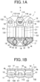
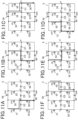
- FIG. 1A is the plan view of the stepping motor according to the embodiment and FIG. 1B is the front view of the stepping motor when seen in the direction indicated by the arrow b in FIG. 1A .
- the stepping motor 1 includes a stator 11, a rotor 15 and three coils C1, C2 and C3 which are magnetically connected to the stator 11.
- the rotor 15 is a magnet which is two-pole magnetized in the radial direction.
- the white part of the rotor 15 is the S polar and the shaded part of the rotor 15 is the N polar.
- the rotor 15 is formed in an approximately disk shape and a rotating shaft (not shown) is provided at the center of the rotor 15.
- a permanent magnet such as a rare earth metal magnet (for example, a samarium-cobalt magnet and the like) or the like is preferably used, for example.
- a rare earth metal magnet for example, a samarium-cobalt magnet and the like
- the type of magnet used for the rotor 15 is not limited to such example.
- the rotor 15 is housed in the after-mentioned rotor receiving section 115 of the stator 11 and is disposed so as to rotate around the rotating shaft, the rotating shaft being the center of rotation.
- the rotor 15 rotates in steps of predetermined degrees (in the embodiment, 60 degrees) in the forward direction (that is, in the clock-wise direction) and in the backward direction (that is, in the counter clock-wide direction) in the rotor receiving section 115 by driving pulses being sequentially applied to the after-mentioned three coils, to one coil at a time (the first coil C1, the second coil C2, the third coil C3) .
- gears or the like (not shown) forming a gear train mechanism for moving the hands of a time display device such as a watch (for example, the after-mentioned time piece 500, see FIG. 7 ) are connected.
- the rotating shaft makes the gears rotate by rotation of the rotor 15.
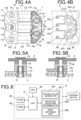
- FIG. 2A is the plan view of the stator
- FIG. 2B is a side view of the stator when seen in the direction indicated by the arrow b in FIG. 2A
- FIG. 2C is the plan view showing the state where the first coil C1 and the coil substrate 16 are mounted on the stator shown in FIG. 2A
- FIG. 2D is the front view of the stator when seen in the direction indicated by the arrow d in FIG. 2C .
- the stator 11 includes a straight part 111, a projecting part 112 which projects in the direction orthogonal to the extending direction of the straight part 111 from one side of the straight part 111 and a projecting part 113 which projects in the direction orthogonal to the extending direction of the straight part 111 from the other side of the straight part 111.
- the straight part 111 forms the center yoke of the stepping motor 1.
- the first coil C1 is formed by winding a coil around the straight part 111.
- At least one is an integrated coil which is integrally formed by winding a coil around a part of the stator 11.
- the first coil C1 which is formed around the straight part 111 of the stator 11 is the integrated coil.
- the first side yoke 12 around which the second coil C2 is formed and the second side yoke 13 around which the third coil C3 is formed are respectively engaged with the projecting parts 112 and 113.
- the three coils C1, C2 and C3 are disposed in parallel as shown in FIG. 1A and the like.
- the heights of the parts where the second coil C2 and the third coil C3 are formed (the after-mentioned the first side yoke straight part 121 and the second side yoke straight part 131) will also be higher comparing to the stator 11 by the thickness of the projecting parts 112 and 113.
- the heights of the three coils C1, C2 and C3 may be adjusted so as to be approximately in flash with each other. Therefore, when mounting the stepping motor 1, it can be disposed in a small mounting space in a compact manner.
- the stator 11 according to the embodiment is formed by a material having a high magnetic permeability such as permalloy C (PC), for example.
- PC permalloy C
- permalloy B whose saturation magnetic flux density is greater than that of permalloy C (PC) and in which saturating the magnetic flux is more difficult in comparison to permalloy C (PC) is used.
- the number of windings in the first coil C1 formed in the stator 11 be the same as the number of windings in the second coil C2 and the third coil C3 respectively formed around the first side yoke 12 and the second side yoke 13, it is preferred to assure a sufficient magnetic path by making the cross section area of the straight part 111 of the stator 11 (the area of the cross section which is orthogonal to the flow of the magnetic flux) be larger (specifically, about times 1.5 to times 2) than that of the first side yoke straight part 121 and the second side yoke straight part 131 of the first side yoke 12 and the second side yoke 13, respectively, so that the magnetic flux which flows through the first coil C1 will not be saturated.
- the rotor receiving section 115 which is an approximately circle hole and in which the rotor 15 is housed is formed.
- the rotor receiving section 115 is provided with stator-side stoppers 116 along the outer circumference of the rotor 15 by having equal spaces therebetween.
- the stator-side stoppers 116 are for maintaining the still state of the rotor 15.
- the stator-side stoppers 116 are six concaves (that are, notches) formed on the inner surface of the rotor receiving section 115 of the stator 11.
- the polar boundary position of the rotor 15 is a position on the surface of the rotor 15 located circumferentially at the center between two magnetic poles of the rotor 15. As shown in FIG. 1A , there are two polar boundary positions on the rotor 15. In case where the rotor 15 has a circular cylindrical shape, each of the polar boundary position forms a straight line on the rotor 15.
- the projecting parts 112 and 113 of the stator 11 are respectively provided with two screw holes 119 through which screws 19 (see FIG. 1A and the like) for fixating the stepping motor 1 to the main plate 3 (see FIGS. 5A and 5B ) and the like are to be inserted.
- the coil substrate 16 is mounted on the projecting part 113 of the stator 11 at the approximately center part thereof in the width direction of the projecting part 113, avoiding the screw holes 119.
- the coil substrate 16 is provided with the connecting point t3 and the connecting point t4 where the terminals of the first coil C1 are connected.
- the coil substrates 17 and 18 which are provided respectively corresponding to the after-mentioned coils C2 and C3 of the first side yoke 12 and the second side yoke 13 cover the one halves of the screw holes 119.
- the coil substrates 17 and 18 are respectively provided with the connecting points t1 and t4 and the connecting points t1 and t4 in shapes that allow connection with the main substrate 2 at around the screw holes 119.
- the coil substrate 16 is formed in a shape that covers the other halves of the screw holes 119 and that compensates the coil substrates 17 and 18. With respect to the coil substrate 16, only the parts corresponding to the screw holes 119 are cut out and the two connecting points t3 and t4 which are to be connected with the first coil C1 extend toward the screw holes 119.
- the stator 11 on which the coil substrate 16 is disposed and the first side yoke 12 and the second side yoke 13 on which the coil substrates 17 and 18 are respectively disposed can be fixated by being screwed by the two screws 19.
- a spacer 4a is disposed between the projecting part 113 and the coil substrate 16.
- the spacer 4a is formed to have a thickness so that the upper surface of the spacer 4a be at roughly the same height as the first coil C1.
- the coil substrate 16 is disposed roughly at the height of the first coil C1 or slightly higher than the first coil C1.
- the terminals of the three coils C1, C2 and C3 in the stepping motor 1 are respectively connected with the connecting points of the coil substrates 16, 17 and 18 (that is, with the connecting points t1 to t4) and are electrically connected with the after-mentioned motor drive circuit 5 (see FIG. 6 ).
- the connecting points provide electrical, magnetic and functional connections.
- the connecting points t1, t2, t3 and t4 are such connecting points.
- a part of the connecting points are commonly used. Specifically, one of the terminals of each of the three coils C1, C2 and C3 is connected to the connecting point t4 and in such way, the connecting point t4 is commonly used by the three coils C1, C2 and C3.
- the three coils C1, C2 and C3 are controlled by the four connecting points. If one coil is to be activated (for example, the first coil C1), the commonly used connecting point t4 and another connecting point to which the other terminal of the coil is connected (for example, the connecting point t3 in the case of the first coil C1) is made to be in the ON state so as to activate the coil (for example, the first coil C1) and the connection points to which the other terminals of the other coils (for example, the second coil C2 and the third coil C3) are connected (for example, the connection point t1 to which the second coil C2 is connected and the connecting point t2 to which the third coil C3 is connected) other than the connecting point t4 are made to be in the OFF state. Thereby, a current can be made to flow only through the activated coil (for example, the first coil C1).
- FIG. 3A is the plan view of the first side yoke and the second side yoke
- FIG. 3B is the plan view showing the state where the second coil C2 and the third coil C3 and the coil substrates 17 and 18 are respectively mounted on the first side yoke and the second side yoke shown in FIG. 3A
- FIG. 3C is the front view of the first side yoke and the second side yoke when seen in the direction indicated by the arrow c in FIG. 2B .
- the first side yoke 12 and the third side yoke 13 are respectively disposed on both sides of the straight part 111 of the stator 11 at approximately bisymmetric positions, the straight part 111 being in the middle (in the embodiment, the first side yoke 12 is disposed on the right side in FIG. 1A and the third side yoke 13 is disposed on the left side in FIG. 1A ).
- the first side yoke 12 and the second side yoke 13 of the embodiment are formed by a material having a high magnetic permeability such as permalloy B (PB) or the like, for example.
- PB permalloy B
- permalloy B which is used to form the first side yoke 12 and the second side yoke 13 has greater saturation magnetic flux density and the magnetic flux does not easily saturate comparing to permalloy C which is used to form the stator 11.
- the number of windings in the first coil C1 formed in the stator 11 be the same as the number of windings in the second coil C2 and the third coil C3 respectively formed around the first side yoke 12 and the second side yoke 13, it is preferred to adjust the cross-section area of the straight part 111 of the stator 11 be larger or in other ways so that the magnetic flux which flows through the first coil C1 will not be saturated.
- a first side yoke 12 includes the first side yoke straight part 121, a first side yoke first projecting part 122 which is disposed on one side of the first side yoke straight part 121, the width thereof being wider than that of the first side yoke straight part 121, and a first side yoke second projecting part 123 which is disposed on the other side of the first side yoke straight part 121, the width thereof being wider than that of the first side yoke straight part 121.
- a coil is wound around the first side yoke straight part 121 to form the second coil C2.
- a screw hole 128 through which a screw 19 is inserted is formed in the first side yoke first projecting part 122 at the position corresponding to the screw hole 119 formed in the projecting part 112 of the stator 11 (in the embodiment, the screw hole 119 on the right side in FIGS. 2A and 2C ).
- a first concave 129 which is cut out so as not to block the inserting of the screw 19 (see FIG. 1A and the like) is formed in the first side yoke second projecting part 123 at the position corresponding to the screw hole 119 formed in the projecting part 113 of the stator 11 (in the embodiment, the screw hole 119 on the right side in FIGS. 2A and 2C ).
- the first side yoke 12 is fixated and integrated to the stator 11 by being screwed by the screw 19 or in other ways in the state where the first side yoke first projecting part 122 being layered on the projecting unit 112 of the stator 11 and the first side yoke second projecting part 123 being layered on the projecting part 113 of the stator 11.
- the second coil C2 is magnetically connected with the projecting parts 112 and 113 of the stator 11.
- the coil substrate 17 in a shape that matches the shape of the first side yoke second projecting part 123 is mounted on the first side yoke second projecting part 123 of the first side yoke 12 so as to cover approximately the entire surface of the first side yoke second projecting part 123. That is, the coil substrate 17 is formed in a shape so as to cover one half of the screw hole 119 and a cut out is formed in a shape that matches the first concave 129 of the first side yoke second projecting part 123 at the position corresponding to the screw hole 119.
- the coil substrate 17 is provided with the connecting point t1 and the connecting point t4 where the terminals of the second coil C2 are connected, the connecting points t1 and t4 being formed in shapes that allow them to come in contact with the main substrate 2 at around the screw hole 119.
- the second coil C2 is electrically connected with the after-mentioned motor drive circuit 5 (see FIG. 9A and the like) by the terminals thereof being connected with the connecting points t1 and t4.
- the connecting point t4 is commonly used by the three coils C1, C2 and C3 as described above.
- a spacer 4b is disposed between the first side yoke second projecting part 123 and the coil substrate 17.
- the spacer 4b is formed to have a thickness so that the upper surface of the spacer 4b be at roughly the same height as the second coil C2.
- the coil substrate 17 be disposed at roughly the same height as the second coil C2 or slightly higher than the second coil C2.
- the spacer 4b is formed to have a thickness that is thinner comparing to the thickness of the spacer 4a which is disposed between the coil substrate 16 and the projecting part 113 in the stator 11 by the thickness of the first side yoke second projecting part 123 of the first side yoke 12.
- the second side yoke 13 similarly to the first side yoke 12, the second side yoke 13 includes a second side yoke straight part 131, a second side yoke first projecting part 132 which is disposed on one side of the second side yoke straight part 131, the width thereof being wider than that of the second side yoke straight part 131, and a second side yoke second projecting part 133 which is disposed on the other side of the second side yoke straight part 131, the width thereof being wider than that of the second side yoke straight part 131.
- a coil is wound around the second side yoke straight part 131 to form the third coil C3.
- a screw hole 138 through which a screw 19 is inserted is formed in the second side yoke first projecting part 132 at the position corresponding to the screw hole 119 formed in the projecting part 112 of the stator 11 (in the embodiment, the screw hole 119 on the left side in FIGS. 2A and 2C ).
- a second concave 139 which is cut out so as not to block the inserting of the screw 19 (see FIG. 1A and the like) is formed in the second side yoke second projecting part 133 at the position corresponding to the screw hole 119 formed in the projecting part 113 of the stator 11 (in the embodiment, the screw hole 119 on the left side in FIGS. 2A and 2C ).
- the second side yoke 13 is fixated and integrated to the stator 11 by being screwed by the screw 19 or in other ways in the state where the second side yoke first projecting part 132 being layered on the projecting unit 112 of the stator 11 and the second side yoke second projecting part 133 being layered on the projecting part 113 of the stator 11.
- the third coil C3 is magnetically connected with the projecting parts 112 and 113 of the stator 11.
- the coil substrate 18 in a shape that matches the shape of the second side yoke second projecting part 133 is mounted on the second side yoke second projecting part 133 of the second side yoke 13 so as to cover approximately the entire surface of the second side yoke second projecting part 133. That is, the coil substrate 18 is formed in a shape so as to cover one half of the screw hole 119 and a cut out is formed in a shape that matches the second concave 139 of the second side yoke second projecting part 133 at the position corresponding to the screw hole 119.
- the coil substrate 18 is provided with the connecting point t2 and the connecting point t4 where the terminals of the third coil C3 are connected, the connecting points t2 and t4 being formed in shapes that allow them to come in contact with the main substrate 2 at around the screw hole 119.
- the third coil C3 is electrically connected with the after-mentioned motor drive circuit 5 by the terminals thereof being connected with the connecting points t2 and t4.
- the connecting point t4 is commonly used by the three coils C1, C2 and C3 as described above.
- a spacer 4b is disposed between the second side yoke second projecting part 133 and the coil substrate 18.
- the spacer 4b is formed to have a thickness so that the upper surface of the spacer 4b be at roughly the same height as the third coil C3.
- the coil substrate 18 be disposed at roughly the same height as the third coil C3 or slightly higher than the third coil C3.
- the spacer 4b is formed to have a thickness that is thinner comparing to the thickness of the spacer 4a which is disposed between the coil substrate 16 and the projecting part 113 in the stator 11 by the thickness of the second side yoke second projecting part 133 of the second side yoke 13 and is formed to have the same thickness as the spacer 4b which is disposed between the coil substrate 17 and the first side yoke second projecting part 123 of the first side yoke 12.
- FIG. 4A is the plan view of the stepping motor 1 in its completed state where the coil substrates 16, 17, 18 and the like are mounted thereon and FIG. 4B shows an example of the main substrate 2 on which the stepping motor 1 is mounted.
- FIG. 4A the main substrate 2 is omitted.
- FIG. 4B only the part in the main substrate 2 where the stepping motor 1 is mounted is shown.
- FIG. 5A is the cross-sectional view cut along the line a-a in FIG. 4A which shows the positional relation of individual components when the stepping motor 1 is mounted on the main substrate 2
- FIG. 5B is a cross-sectional view cut along the line b-b in FIG. 4A which shows the positional relation of individual components when the stepping motor 1 is mounted on the main substrate 2.
- the connecting parts where the terminals of the three coils C1, C2 and C3 connect with the connecting points t1, t2, t3 and t4 in the coil substrates 16, 17 and 18 are resin covered regions 16a, 17a and 18a where the welding protective resin for protecting the connecting parts is applied.
- cutouts 26, 27 and 28 are formed in the main substrate 2 at the positions corresponding to the resin covered regions 16a, 17a and 18a and when the stepping motor 1 is mounted on the main substrate 2, the resin covered regions 16a, 17a and 18a are respectively disposed in the cutouts 26, 27 and 28.
- the main substrate 2 is provided with terminals 22a, 22b, 22c and 22d for coils to be connected.
- the connecting point t1 of the coil-side is connected to the terminal 22a
- the connecting point t2 of the coil-side is connected to the terminal 22b
- the connecting point t3 of the coil-side is connected to the terminal 22c
- the connecting point t4 of the coil side is connected to the terminal 22d.
- the connecting points t1, t2, t3 and t4 being respectively connected with the terminals 22a, 22b, 22c and 22d for the coils to be connected, the three coils C1, C2 and C3 are electrically connected with the main substrate 2.
- the stepping motor 1 is to be fixated between the main substrate 2 and the main plate 3 of a module or the like which is not shown.
- hollow supporting column members 31 in which the tips of the screws 19 are to be inserted are formed.
- fitting screw parts are formed in the supporting column members 31 and on the outer circumferences of the screws 19 and the screws 19 and the supporting column members 31 are respectively screwed to each other, for example.
- the method for fixating the screws 19 in the supporting column members 31 is not limited to such example.
- the screws 19 and the supporting column members 31 can be fixated by pressing the tips of the screws 19 in the supporting column members 31 of the main plate 3.
- FIG. 5A is a cross-sectional view cut along the line a-a in FIG. 4A when the stepping motor 1 is mounted between the main substrate 2 and the main plate 3 and
- FIG. 5B is a cross-sectional view cut along the line b-b in FIG. 4A .
- the stepping motor 1 is fixated to the main substrate 2 by inserting the screws 19 in the substrate-side screw holes 219 of the main substrate 2 toward the stepping motor 1 side and by screwing the tips of the screws 19 in the supporting columns members 31 of the main plate 3.
- the spacers 4b which are disposed between the coil substrate 17 disposed on the first side yoke 12 and the first side yoke second projecting part 123 and between the coil substrate 18 disposed on the second side yoke 13 and the second side yoke second projecting part 133 are thinner comparing to the spacer 4a which is disposed between the coil substrate 16 disposed on the stator 11 and the projecting part 113 by the thickness of the first side yoke second projecting part 123 and the second side yoke second projecting part 133 (see FIG. 5A and 5B ). Therefore, as shown in FIG. 1B , the three coil substrates 16, 17 and 18 are disposed so as to be approximately in flash with each other in the state where the stepping motor 1 is assembled. Thus, the entire stepping motor 1 is formed in a compact form which can be easily mounted.
- the motor drive device for driving the stepping motor 1 according to the embodiment will be described.
- the motor drive device includes the after-mentioned driving pulse generator 651, switching elements 51 to 58 (after-mentioned) and a motor drive circuit 5.
- the stepping motor 1 of the embodiment is for driving the hand moving mechanism which moves the hands 502 (see FIG. 7 ) of the time piece 500 (see FIG. 7 ).
- FIG. 6 is a block diagram of the main components showing the controlling structure according to the embodiment.
- the time piece 500 includes a controller 6 for controlling the operation of individual components of the time piece.
- the controller 6 includes a CPU (Central Processing Unit) 61, a ROM (Read Only Memory) 62, a RAM (Random Access Memory) 63, an oscillator (indicated as "OSC” in FIG. 6 ) 64, a motor controller 65 and the like.
- CPU Central Processing Unit
- ROM Read Only Memory
- RAM Random Access Memory
- OSC oscillator
- controller 6 is not specifically limited, it is configured by including a LSI (Large Scale Integration) or the like, for example.
- LSI Large Scale Integration
- the CPU 61 outputs various types of commands to the motor controller 65 on the basis of the control program stored in the ROM 62.
- the RAM 63 is used as the working memory of the CPU 61.
- the oscillator 64 In combination with an oscillator (not shown), the oscillator 64 generates unique frequency signals and outputs an operation clock to the CPU 61 and the like.
- the motor controller 65 includes a driving pulse generator 651 which generates driving pulses and outputs the driving pulses to the motor drive circuit 5, the rotation detection determinator 652 which determines whether the rotor 15 rotates normally, the first switching unit 653 and the like.
- the driving pulse generator 651 outputs a driving pulse to a switching element (in the embodiment, the first switching unit 653 including switching elements 51 to 58 (after-mentioned)) when driving the stepping motor 1.
- the driving pulse generator 651 outputs driving pulses to the switching elements 51 to 58 so that a current for driving the coils C1, C2 and C3 flows through one path.
- magnetic poles (the first magnetic pole, the second magnetic pole and the third magnetic pole) are generated at positions in the stator 11 of the stepping motor 1 along the outer circumference of the rotor 15, the positions corresponding to the 1/3 positions of the outer circumference of the rotor.
- the driving pulse generator 651 outputs driving pulses to the switching elements 51 to 58 as needed so as to sequentially drive the coils C1, C2 and C3 in the stepping motor 1, one coil at a time.
- the polarities of the magnetic poles (the first magnetic pole, the second magnetic pole and the third magnetic pole) which are generated along the outer circumference of the rotor 15 are sequentially switched.
- the first switching unit 653 includes the switching elements 51 to 58 which are inner switches provided inside the controller 6 which is formed of a LSI or the like and the first switching unit 653 controls the path through which the current for driving the coils C1, C2 and C3 flows.
- the motor drive circuit 5 of the embodiment is a bridge circuit which drives the stepping motor 1 provided with three coils C1, C2 and C3.
- a current flows through a predetermined path by the switching elements 51 to 58 (after-mentioned) being switched between ON and OFF as needed in accordance with the driving pulses which are output from the driving pulse generator 651.
- FIGS. 9A to 9F show circuits showing structure examples of the motor drive circuit 5 according to the embodiment.
- the power voltage Vcc (not shown) is applied between the voltage input terminal 59 and the ground terminal 60.
- three coils C1, C2 and C3 and a plurality of switching elements 51 to 58 are disposed between the voltage input terminal 59 and the ground terminal 60.
- FETs Field Effect Transistors
- the switching element 51 is disposed between the voltage input terminal 59 and the connecting point t1 which is connected with the second coil C2
- the switching element 52 is disposed between the voltage input terminal 59 and the connecting point t2 which is connected with the third coil C3
- the switching element 53 is disposed between the voltage input terminal 59 and the connecting point t3 which is connected with the first coil C1.
- the switching element 54 is disposed between the voltage input terminal 59 and the connecting point t4 which is the commonly used connecting point to which the three coils C1, C2 and C3 are connected.
- the switching element 55 is disposed between the connecting point t1 and the ground terminal 60
- the switching element 56 is disposed between the connecting point t2 and the ground terminal 60
- the switching element 57 is disposed between the connecting point t3 and the ground terminal 60
- the switching element 58 is disposed between the connecting point t4 and the ground terminal 60.
- the configuration of the motor drive circuit 5 is not limited to such example and can be modified as needed.
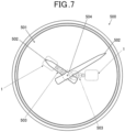
- FIG. 7 is a schematic view showing a structure example of a case where the stepping motor 1 and the motor drive device of the embodiment is applied as the drive source to drive the hand moving mechanism (gear train mechanism) of the hands of a time display device such as a watch.
- the stepping motor 1 and the motor drive device of the embodiment are used as the drive source for making the hand moving mechanism (gear train mechanism) 503 operate so as to move the hands 502 (in FIG. 7 , only the hour hand and the minute hand are shown.
- the hands are not limited to the example shown in the drawing.) of the time piece 500 which is a time display device provided with an analog display 501, for example.
- the rotating shaft of the rotor 15 is connected with a gear in the hand moving mechanism (gear train mechanism) 503.
- the hand moving mechanism gear train mechanism
- the motor drive device controls the stepping motor 1 so that the three coils C1, C2 and C3 sequentially be applied current, one coil at a time.
- the stepping motor 1 When the stepping motor 1 is to be assembled, first, crushing of the straight part 111 of the stator 11 is carried out so that the straight part 111 be higher comparing to the projecting parts 112 and 113 by the thickness of the projecting parts 112 and 113 and then, the first coil C1 is formed by winding a coil around the straight part 111. Thereafter, the second coil C2 is formed by winding a coil around the first side yoke straight part 121 of the first side yoke 12 and the third coil C3 is formed by winding a coil around the second side yoke straight part 131 of the second side yoke 13.
- the three coils C1, C2 and C3 are formed with the same number of windings (the number of turns).
- the number of windings in each of the coils C1, C2 and C3 may be changed as needed according to the material, the cross-section area, etc. of each of the straight part 111, the first side yoke straight part 121, the second side yoke straight part 131 around which the coils C1, C2 and C3 are respectively formed.
- the positions of the screw holes 119 in the stator 11 and the screw holes 128 and 138 in the first side yoke 12 and the second side yoke 13 are matched and the projecting part 112 of the first side yoke 12 and the second side yoke first projecting part 132 of the second side yoke 13 are layered on the projecting part 112 of the stator 11.
- the stator 11 is lower than the first side yoke 12 and the second side yoke 13
- the heights of the three coils C1, C2 and C3 will be approximately in flash with each other (see FIG. 1B ) since crushing is performed on the straight part 111 of the stator 11 as described above.
- the spacer 4a is placed at the approximately center of the projecting part 113 of the stator 11 and place the coil substrate 16 is placed on the spacer 4a.
- the spacer 4b which is thinner comparing to the spacer 4a by the thickness of the first side yoke second projecting part 123 is placed on the first side yoke second projecting part 123 of the first side yoke 12 and the coil substrate 17 is placed on the spacer 4b.
- the spacer 4b which is thinner comparing to the spacer 4a by the thickness of the second side yoke second projecting part 133 is placed on the second side yoke second projecting part 133 of the second side yoke 13 and the coil substrate 18 is placed on the spacer 4b.
- the coil substrates 16, 17 and 18 are slightly higher than the coils C1, C2 and C3 and the three coil substrates 16, 17 and 18 are aligned so as to be approximately in flash with each other (see FIG. 1B ).
- the terminals of the first coil C1 are connected to the connecting points t3 and t4 of the coil substrate 16
- the terminals of the second coil C2 are connected to the connecting points t1 and t4 of the coil substrate 17
- the terminals of the third coil C3 are connected to the connecting points t2 and t4 of the coil substrate 18.
- the protective resin is applied to the connecting parts to form the resin covered regions 16a, 17a and 18a.
- the stepping motor 1 in this state is adjusted so that the positions of the screw holes 119 match the positions of the supporting column members 31 and place the stator 11, the first side yoke 12 and the second side yoke 13 (the stepping motor 1) on the main plate 3. Then, the substrate-side screw holes 219 in the main substrate 2 are matched to the positions of the supporting column members 31 and the screw holes 119 and the main substrate 2 is places on the stepping motor 1 from the above.
- the screws 19 are inserted in the substrate-side screw holes 219 and the screw holes 119 in the stator 11, two of each are formed at the positions corresponding to the projecting part 112 and the projecting part 113, and the screws 19 are screwed in so that the tips of the screws 19 be fixated inside the supporting column members 31 of the main plate 3.
- the stator 11, the first side yoke 12 and the second side yoke 13 are tightened together by the screw 19 and the stepping motor 1 is fixated to the main plate 3 and the main substrate 2.
- the terminals of the coils C1, C2 and C3 connected to the coil substrates 16, 17 and 18 are electrically connected with the terminals 22a to 22d for the coils to be connected on the main substrate 2.
- the stepping motor 1 will not move when it is fixated to the main plate 3 and the main substrate 2 and the stepping motor 1 can be mounted efficiently with no waste in the mounting space.
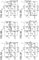
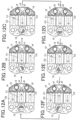
- FIGS. 8A to 8F show the positions of the rotor 15 in its rotating direction and the flow of the magnetic fluxes (indicated by the arrows in the drawings) which flows through the coils C1, C2 and C3 in the case where the rotor 15 rotates in the forward direction (that is, the rotor 15 rotates in the clock-wide direction indicated by the arrows in FIG. 8A and the like).
- "S" and "N" around the rotor receiving section 115 indicate the polarities of the magnetic poles (the first magnetic pole, the second magnetic pole, and the third magnetic pole) which are generated around the rotor receiving section 115 when current is applied.
- FIGS. 9A to 9F correspond to FIGS. 8A to 8F and each of the arrows in the drawings indicates a current flow.
- the switching elements 51, 56, 57 and 58 in the motor drive circuit 5 are made to be in the ON state and the switching elements 52, 53, 54 and 55 are made to be in the OFF state.
- the power voltage Vcc is applied to the second coil C2 and the current flows to the direction toward the connecting point t4 from the connecting point t2.
- the switching element 51, 53, 54 and 56 in the motor drive circuit 5 are made to be in the ON state and the switching elements 52, 55, 57 and 58 are made to be in the OFF state.
- the power voltage Vcc is applied to the third coil C3 and the current flows in the direction toward the connecting point t2 from the connecting point t4.
- the switching elements 53, 55, 56 and 58 are made to be in the ON state and the switching elements 51, 52, 54 and 57 are made to be in the OFF state.
- the power voltage Vcc is applied to the first coil C1 and the current flows in the direction toward the connecting point t4 from the connecting point t3.
- the switching elements 52, 53, 54 and 55 in the motor drive circuit 5 are made to be in the ON state and the switching elements 51, 56, 57 and 58 are made to be in the OFF state.
- the power voltage Vcc is applied to the second coil C2 and the current flows in the direction toward the connecting point t1 from the connecting point t4.
- the switching elements 52, 55, 57 and 58 in the motor drive circuit 5 are made to be in the ON state and the switching elements 51, 53, 54 and 56 are made to be in the OFF state.
- the power voltage Vcc is applied to the third coil C3 and the current flows in the direction toward the connecting point t4 from the connecting point t2.
- the switching elements 51, 52, 54 and 57 in the motor drive circuit 5 are made to be in the ON state and the switching elements 53, 55, 56 and 58 are made to be in the OFF state.
- the power voltage Vcc is applied to the first coil C1 and the current flows in the direction toward the connecting point t3 from the connecting point t4.
- the state returns to the state as shown in FIGS. 8A and 9A and the rotor 15 returns to its original position after rotating 360 degrees from the initial position.
- the driving pulse generator 651 outputs the driving pulses to the motor drive circuit 5 so that the current for driving the coils C1, C2 and C3 flows through one path in the embodiment.
- the driving pulse generator 651 outputs the driving pulses to the motor drive circuit 5 so that only one of the coils C1, C2 and C3 be driven in order to sequentially drive the coils C1, C2 and C3 one coil at a time. Therefore, comparing to a case where two or more coils are in parallel and made to be applied current, the power can be saved even more.
- the stepping motor 1 is provided with three coils C1, C2 and C3 and at least one of the three coils C1, C2 and C3 (in the embodiment, the first coil C1) is the integrated coil which is integrally formed with the stator by winding a coil around a part of the stator 11. Therefore, the stepping motor 1 including three coils C1, C2 and C3 can be made to have the minimum mounting area without complicating or enlarging the configuration of the stepping motor 1. Such stepping motor can be used in a small size watch or the like which requires high density mounting.
- the stator 11 includes the straight part 111 and the first coil C1 which is the integrated coil formed integrally with the stator 11 is formed by winding a coil around the straight part 111. Therefore, similarly to the case where a coil is wound around a coil core which is exclusively used for forming a coil, the winding of a coil can be carried out evenly around the straight part 111.
- the other coils of the three coils C1, C2 and C3 are magnetically connected with the projecting part 113 of the stator 11. In such way, all of the three coils can operate as the coils forming the stepping motor 1.
- the coils are individual components and they can be assembled to be integrated after completing each coil by winding a coil around each winding part. Therefore, the stepping motor 1 including three coils C1, C2 and C3 can be made without degrading the assembling efficiency of the stepping motor 1.
- the rotor receiving section 115 is provided with the stator-side stoppers 116 around the outer circumference of the rotor 15 with approximately equal spaces therebetween and the rotor 15 holds still at the position where the polar boundary position of the rotor 15 and any one of the stator-side stoppers 116 face each other. In such way, by having the stator-side stoppers 116, it can be assured that the rotor 15 holds still at a desired position and a highly precise motor can be made.
- stator 11, the first side yoke 12 and the second side yoke 13 are tightened together by four screws 19 to be fixated to the main plate 3 and the main substrate 2.
- the waste in the mounting area can be cut, the manufacturing cost can be reduced by the number of components being reduced and the assembling efficiency can be improved.
- a rotor of a stepping motor which can realize rotation in small steps such as in steps of 60 degrees or the like
- different types of magnets may be used.
- the embodiment solves such problem by using a disk shaped magnet which is two-pole magnetized in the radius direction as the rotor 15 of the stepping motor 1. Comparing to the case where a different type of magnet is used, manufacturing is easy and can also be easily assembled in a rotor.
- a stepping motor including two coils
- steps which readily receive the influence of the back electromotive force of the coils
- steps which does not receive such influence in the steps with respect to the yokes at three positions (center yoke and a pair or side yokes). Therefore, the step angles easily become uneven and it is difficult to smoothly rotate the rotor.
- the embodiment solves such problem by having three coils C1, C2 and C3 and by sequentially driving the three coils one coil at a time to rotate the rotor 15. In such way, the step angles are stable and the rotor 15 can rotate smoothly and thus, a highly accurate stepping motor can be made. In such way, a smooth hand movement can be realized and this is especially effective in the case of sweep movement of the second hand, for example.
- the driving pulse generator 651 outputs driving pulses to the switching elements 51 to 58 in the first switching unit 653 as needed so that the current for driving the coils C1, C2 and C3 flows through one path.
- the driving pulse generator 651 output driving pulses so as to sequentially drive the three coils C1, C2 and C3 in the stepping motor 1 one coil at a time. Therefore, even though the stepping motor includes three coils C1, C2 and C3, the power can be saved more comparing to the case where a current flows through two or more paths.
- the driving pulse generator 651 outputting driving pulses to the switching elements 51 to 58 as needed so as to sequentially drive the three coils C1, C2 and C3 one coil at a time, the polarities of the first magnetic pole, the second magnetic pole and the third magnetic pole which are generated in the stator 11 can be sequentially switched. In such way, the rotor 15 can be made to rotate in accurate step angles and a highly precise stepping motor 1 can be made while saving the power.
- the controlling of output of driving pulses to the switching elements 51 to 58 by the driving pulse generator 651 is not limited to the example described in the embodiment.
- the coils other than the coil which is driven may be in the high impedance state.
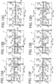
- FIGS. 10A to 10F corresponds to FIGS. 8A to 8F , respectively.
- the driving pulse generator 651 controls the motor drive circuit 5 by outputting driving pulses to the switching elements 51 to 58 in the first switching unit 653 as needed so as to only make the switching elements 51 and 56 be in the ON state and to make the other switching elements be in the OFF state. In such way, as shown in FIGS.
- the power voltage Vcc is applied only to the second coil C2, the current paths are blocked in the other coils which are the first coil C1 and the third coil C3 (that is, the first coil C1 and the third coil C3 are virtually cut off from the motor drive circuit 5) and the first coil C1 and the third coil C3 are made to be in the high impedance state.
- the driving pulse generator 651 controls the motor drive circuit 5 by outputting driving pulses to the switching elements 51 to 58 in the first switching unit 653 as needed so as to only make the switching elements 53 and 56 be in the ON state and the other switching elements be in the OFF state. In such way, as shown in FIGS.
- the power voltage Vcc is applied only to the third coil C3, the current paths are blocked in the other coils which are the first coil C1 and the second coil C2 (that is, the first coil C1 and the second coil C2 are virtually cut off from the motor drive circuit 5) and the first coil C1 and the second coil C2 are made to be in the high impedance state.
- the driving pulse generator 651 controls the motor drive circuit 5 by outputting driving pulses to the switching elements 51 to 58 in the first switching unit 653 as needed so as to only make the switching elements 53 and 58 be in the ON state and the other switching elements be in the OFF state. In such way, as shown in FIGS.
- the power voltage Vcc is applied only to the first coil C1, the current paths are blocked in the other coils which are the second coil C2 and the third coil C3 (that is, the second coil C2 and the third coil C3 are virtually cut off from the motor drive circuit 5) and the second coil C2 and the third coil C3 are made to be in the high impedance state.
- the driving pulse generator 651 controls the motor drive circuit 5 by outputting driving pulses to the switching elements 51 to 58 in the first switching unit 653 as needed so as to only make the switching elements 52 and 55 be in the ON state and the other switching elements be in the OFF state. In such way, as shown in FIGS.
- the power voltage Vcc is applied only to the second coil C2, the current paths are blocked in the other coils which are the first coil C1 and the third coil C3 (that is, the first coil C1 and the third coil C3 are virtually cut off from the motor drive circuit 5) and the first coil C1 and the third coil C3 are made to be in the high impedance state.
- the driving pulse generator 651 controls the motor drive circuit 5 by outputting driving pulses to the switching elements 51 to 58 in the first switching unit 653 as needed so as to only make the switching elements 52 and 57 be in the ON state and the other switching elements be in the OFF state. In such way, as shown in FIGS.
- the power voltage Vcc is applied only to the third coil C3, the current paths are blocked in the other coils which are the first coil C1 and the second coil C2 (that is, the first coil C1 and the second coil C2 are virtually cut off from the motor drive circuit 5) and the first coil C1 and the second coil C2 are made to be in the high impedance state.
- the driving pulse generator 651 controls the motor drive circuit 5 by outputting driving pulses to the switching elements 51 to 58 in the first switching unit 653 as needed so as to only make the switching elements 54 and 57 be in the ON state and the other switching elements be in the OFF state. In such way, as shown in FIGS.
- the power voltage Vcc is applied only to the first coil C1, the current paths are blocked in the other coils which are the second coil C2 and the third coil C3 (that is, the second coil C2 and the third coil C3 are virtually cut off from the motor drive circuit 5) and the second coil C2 and the third coil C3 are made to be in the high impedance state.
- the driving can be carried out with a small current and the power can be saved.
- the rotation detection determinator 652 detects the back electromotive force generated in the coil which is subject to the rotation detection.
- the back electromotive force generated in the coil which is subject to the rotation detection is dispersed to the plurality of coils including the other coils which are not driven (in the embodiment, the three coils C1, C2 and C3) and absorbed by each other causing reduction in the peak of the back electromotive force making it difficult to carry out an accurate rotation detection.
- the coils other than the coil which is made to be applied current be in the high impedance state, dispersion and absorption of the back electromotive force can be prevented from occurring and the accuracy of the rotation detection carried out by the rotation detection determinator 652 can be improved.
- the way of connecting the individual parts in the motor drive circuit 5 and the way to switch the ON/OFF state are not limited to the examples described in the embodiment.
- the driving pulse generator 651 controls the motor drive circuit 5 by outputting the driving pulses to the switching elements 51 to 58 in the first switching unit 653 as needed so as to only make the switching elements 51, 56, 57 and 58 be in the ON state and the other switching elements be in the OFF state as shown in FIG. 11A .
- the power voltage Vcc is only applied to the second coil C2.
- the driving pulse generator 651 controls the motor drive circuit 5 by outputting driving pulses to the switching elements 51 to 58 in the first switching unit 653 as needed so as to only make the switching elements 53, 54, 55 and 56 be in the ON state and the other switching elements be in the OFF state. In such way, as shown in FIG. 8B and 11B , the power voltage Vcc is only applied to the third coil C3.
- the driving pulse generator 651 controls the motor drive circuit 5 by outputting driving pulses to the switching elements 51 to 58 in the first switching unit 653 as needed so as to only make the switching elements 51, 52, 53 and 58 be in the ON state and the other switching elements be in the OFF state. In such way, as shown in FIG. 8C and 11C , the power voltage Vcc is only applied to the first coil C1.
- the driving pulse generator 651 controls the motor drive circuit 5 by outputting driving pulses to the switching elements 51 to 58 in the first switching unit 653 as needed so as to only make the switching elements 52, 53, 54 and 55 be in the ON state and the other switching elements be in the OFF state. In such way, as shown in FIG. 8D and 11D , the power voltage Vcc is only applied to the second coil C2.
- the driving pulse generator 651 controls the motor drive circuit 5 by outputting driving pulses to the switching elements 51 to 58 in the first switching unit 653 as needed so as to only make the switching elements 51, 52, 57 and 58 be in the ON state and the other switching elements be in the OFF state. In such way, as shown in FIG. 8E and 11E , the power voltage Vcc is only applied to the third coil C3.
- the driving pulse generator 651 controls the motor drive circuit 5 by outputting driving pulses to the switching elements 51 to 58 in the first switching unit 653 as needed so as to only make the switching elements 54, 55, 56 and 57 be in the ON state and the other switching elements be in the OFF state. In such way, as shown in FIG. 8F and 11F , the power voltage Vcc is only applied to the first coil C1.
- driving pulses can also be output to the switching elements 51 to 58 in the first switching unit 653 as needed so that the current for driving the coils C1, C2 and C3 flow through one path in order to sequentially drive the three coils C1, C2 and C3 on coil at a time.
- the stepping motor 1 includes the three coils C1, C2 and C3 similarly to the first embodiment.
- FIGS. 12A to 12F show the magnetic flux which flows through each of the coils C1, C2 and C3 in the case where the rotor 15 of the stepping motor 1 is made to rotate in steps of 60 degrees.
- the arrows indicate the directions of the magnetic fluxes which flow in the coils C1, C2 and C3.
- FIGS. 13A to 13F show the circuit in the motor drive circuit 5 and FIGS. 13A to 13F correspond to the conditions shown in FIGS. 12A to 12F , respectively.
- FIG. 14 is a block diagram of main components showing the controlling structure according to the embodiment.
- the three coils C1, C2 and C3 are connected in series.
- the stepping motor 1 is provided with the second switching unit 654 including the switching elements 61 to 64 for switching the ON/OFF state between the first coil C1, the second coil C2 and the third coil C3 being connected in series, in the embodiment.
- the switching elements 61 to 64 are external switches provided on the main substrate 2 or the like.
- the embodiment since the embodiment includes the switching elements 61 to 64 which are provided as external switches, differently from the first embodiment, the relation between the connecting points t1, t2, t3 and t4 which provide electrical connection, magnetic connection and functional connection and the physical pads on the stepping motor 1 change as needed.
- the driving pulse generator 651 generates driving pules for simultaneously driving the three coils C1, C2 and C3 and outputs the driving pulses to the switching elements 51 to 58 (the first switching unit 653 including the switching elements 51 to 58) and the switching elements 61 to 64 (the second switching unit 654 including the switching elements 61 to 64).
- the driving pulse generator 651 outputs driving pulses as needed to the first switching unit 653 including the switching elements 51 to 58 and the second switching unit 654 including the switching element 61 to 64 so that the current for driving the coils C1, C2 and C3 flow through one path.
- the first switching unit 653 and the second switching unit 654 switch the ON/OFF state of the switching elements 51 to 58 and the switching elements 61 to 64 as needed in accordance with driving pulses.
- the driving pulse generator 651 controls the first switching unit 653 and the second switching unit 654 so as to make the switching elements 51, 57, 61 and 64 be in the ON state and the other switching elements be in the OFF state as shown in FIG. 13A .
- the current flows through one path in the motor drive circuit 5
- all of the three coils C1, C2 and C3 are simultaneously driven and the magnetic fluxes flow in the coils C1, C2 and C3 as shown in FIG. 12A .
- the driving pulse generator 651 controls the first switching unit 653 and the second switching unit 654 so as to make the switching elements 54, 56, 62 and 63 be in the ON state and to the other switching elements be in the OFF state.
- the current flows through one path in the motor drive circuit 5
- all of the three coils C1, C2 and C3 are simultaneously driven and the magnetic fluxes flow in the coils C1, C2 and C3 as shown in FIG. 12B .
- the three magnetic poles that are generated around the rotor 15 are switched and the rotor 15 rotates 60 degrees from the initial state.
- the driving pulse generator 651 controls the first switching unit 653 and the second switching unit 654 so as to make the switching elements 54, 55, 61 and 63 be in the ON state and the other switching elements be in the OFF state.
- the current flows through one path in the motor drive circuit 5
- all of the three coils C1, C2 and C3 are simultaneously driven and the magnetic fluxes flow in the coils C1, C2 and C3 as shown in FIG. 12C .
- the three magnetic poles that are generated around the rotor 15 are switched and the rotor 15 rotates 120 degrees from the initial state.
- the driving pulse generator 651 controls the first switching unit 653 and the second switching unit 654 so as to make the switching elements 53, 55, 61 and 64 be in the ON state and the other switching elements be in the OFF state.
- the current flows through one path in the motor drive circuit 5
- all of the three coils C1, C2 and C3 are simultaneously driven and the magnetic fluxes flow in the coils C1, C2 and C3 as shown in FIG. 12D .
- the three magnetic poles that are generated around the rotor 15 are switched and the rotor 15 rotates 180 degrees from the initial state.
- the driving pulse generator 651 controls the first switching unit 653 and the second switching unit 654 so as to make the switching elements 52, 58, 62 and 63 be in the ON state and the other switching elements be in the OFF state.
- the current flows through one path in the motor drive circuit 5
- all of the three coils C1, C2 and C3 are simultaneously driven and the magnetic fluxes flow in the coils C1, C2 and C3 as shown in FIG. 12E .
- the three magnetic poles that are generated around the rotor 15 are switched and the rotor 15 rotates 240 degrees from the initial state.
- the driving pulse generator 651 controls the first switching unit 653 and the second switching unit 654 so as to make the switching elements 51, 58, 61 and 63 be in the ON state and the other switching elements be in the OFF state.
- the current flows through one path in the motor drive circuit 5
- all of the three coils C1, C2 and C3 are simultaneously driven and the magnetic fluxes flow in the coils C1, C2 and C3 as shown in FIG. 12F .
- the three magnetic poles that are generated around the rotor 15 are switched and the rotor 15 rotates 300 degrees from the initial state.
- the three coils C1, C2 and C3 of the stepping motor 1 are connected in series and all of the coils C1, C2 and C3 are simultaneously activated.
- the resistance in the coils C1, C2 and C3 is tripled. Therefore, if the driving pulse generator 651 inputs the driving pulses having the same pulse width to the motor drive circuit 5, the current consumption is 1/3 comparing to the case where the coils are driven one coil at a time and the magnetic fluxes which are generated in the coils C1, C2 and C3 themselves will be tripled. Thus, the energy efficiency is greatly improved comparing to the case where the coils are connected in parallel and they are driven one coil at a time.
- the stepping motor 1 can further be downsized.
- the rotation detection determinator 652 carries out the rotation detection, if the three coils C1, C2 and C3 are connected in series as in the embodiment, this leads to increase in the peak of the back electromotive force and the accuracy in the rotation detection is expected to be improved.
- stator 11 is formed of permalloy C and the first side yoke 12 and the second side yoke 13 are formed of permalloy B whose saturation magnetic flux density is greater than permalloy C are shown.
- any material can be used to form the stator 11, the first side yoke 12 and the second side yoke 13 as long as the material has high magnetic permeability and the material is not limited to the ones mentioned in the embodiments.
- stator 11, the side yoke 12 and the second side yoke 13 can be formed of permalloy C or all the them can be formed of permalloy B.
- any one of or all of them can be formed of pure iron or the like.
- the first side yoke 12 and the second side yoke 13 are to be formed of the same material, there is no need to consider the difference in the saturation magnetic flux density and the like. Therefore, there is no need to make the cross-section area of the straight part 111 of the stator 11 be larger than the cross-section areas of the first side yoke straight part 121 and the second side yoke straight part 131 of the first side yoke 12 and the second side yoke 13 and the efficiency in design and manufacturing can be improved.
- stepping motor 1 is configured by magnetically connecting the stator 11 which forms the center yoke and the two side yokes (that is, the first side yoke 12 and the second side yoke 13) are shown.
- the configuration of the stator 11 and the side yokes is not limited to such configuration.
- stator 11 which forms the center yoke of the stepping motor and the two side yokes thereof are formed of the same material as described above
- these components can be formed as an integrated component and the three coils C1, C2 and C3 can be formed by winding coils around the straight parts, inserting the coils through between the straight parts.
- the first embodiment describes an example where only one coil is driven and the second embodiment describes an example where the three coils are connected in series and they are simultaneously driven.
- the way of driving the coils is not limited to the examples.
- any two of the coils may be simultaneously driven (for example, the first coil C1 and the second coil C2) .
- stator-side stoppers 116 in the position shifted by 30 degrees from the positions shown in FIG. 1A and the like.
- stator-side stoppers 116 in the above embodiments can be any type as long as sufficient index torque (holding torque) for maintaining the still state of the rotor 15 can be obtained and their shapes and the like are not limited to what are shown as examples in the embodiments. Further, stoppers such as concaves may also be formed on the rotor 15 side.
- the cases where the stepping motor 1 and the motor drive device are used to activate the hand moving mechanism for moving the hands of a time display device such as the time piece 500 and the like are described as examples.
- the stepping motor 1 and the motor drive device are not limited to be used to drive the hand moving mechanism of a time piece.
- the stepping motor 1 and the motor drive device may be applied to a time display device which is provided with other hands and the like.
- the stepping motor 1 and the motor drive device are not limited to be applied to a time display device. They can be applied as the drive source of various types of devices which are driven by motors which are driven in steps of predetermined degrees.
Description
- The present invention relates to a stepping motor, a motor drive device and a time display device.
- Traditionally, there is known a stepping motor which is provided with two coils and which can rotate forward and backward by applying driving pulses to the two coils as needed.
- For example,
JP 2014-195371 - However, with respect to the stepping motors such as the one disclosed in
JP 2014-195371 - Therefore, there has been a problem that the amount of power consumption during the latter period become large and there is a need for further power saving.
- Document
JP 2 881160 B2 -
Document JP 2 881160 B2
A stepping motor, comprising: - a rotor (1) which is two-pole (comprising one distributed N-pole,
fig. 3 ) magnetized in a- radius direction (
fig. 3 ); - a stator (41-43, 31-33, 21-23)
- radius direction (
- which includes a straight part (to which coil 32 is attached,
fig. 1a ), a first projecting part (21, 23) which projects from one end (the upper end infig. 1 ) of the straight part in a direction orthogonal to an extending direction of the straight part (fig. 1a ), a second projecting part (5) which projects from another end (the lower end infig. 1 ) of the straight part in a direction orthogonal to the extending direction of the straight part (to which coil 32 is attached,fig. 1a ), - and a rotor receiving section (said section comprising "notch parts" 21a, 22a, 23a, see
fig. 1b ) for receiving the rotor (1) provided to the first projecting part (21, 23); a first side yoke (43) and a second side yoke (41) which are respectively disposed on both sides of the straight part (to which coil 32 is attached,fig. 1a ) of the stator (41-43, 31-33) at approximately bisymmetric positions (fig. 1 ); - the rotor receiving section (comprising "notch parts" 21a, 22a, 23a, see
fig. 1b ) provided at the approximately center in the width direction (fig. 1a ) of the first projecting part (21, 23), which is at the position where the stator (41-43, 31-33) is, the first side yoke (43) and the second side yoke (41) intersect in the state where the stepping motor is assembled (fig. 1a ); the rotor receiving section (comprising "notch parts" 21a, 22a, 23a, seefig. 1b ) being an approximately circle hole in which the rotor (1) is formed (fig. 1b ); - the first side yoke (43) including a first side yoke straight part (to which coil 33 is wound), a first side yoke first projecting part (fixed to part 23,
fig. 1a ) which is disposed on one side (upper) of the first side yoke straight part (to which coil 33 is wound), - and a first side yoke second projecting part (fixed to part 5) which is disposed on the other (lower) side of the first side yoke straight part (to which coil 33 is wound),
- the second side yoke (41) includes a second side yoke straight part (to which
coil 31 is fixed), a second side yoke first projecting part (fixed to part 21,fig. 1a ), which is disposed on one side (upper side) of the second side yoke straight part (to whichcoil 31 is fixed), - and a second side yoke second projecting part (fixed to part 5) which is disposed on the other side (lower side) of the second side yoke straight part (to which
coil 31 is fixed), - a second coil (33) which is formed by winding a coil around the first side yoke straight part (
fig. 1a ) of the first side yoke (43) and magnetically connected (seefig. 1 ) with the first projecting part (21, 23) and the second projecting part (5) of the stator; and a third coil (31) which is formed by winding a coil around the second side yoke straight part (fig. 1a ) of the second side yoke (41) and magnetically connected with the first projecting part (21, 23) and the second projecting part (5) of the stator, - wherein the stepping motor includes:
- a first integrated coil (32) which is integrally formed with the stator by winding a coil around the straight part (22) of the stator;
- the rotor receiving section (
fig. 1b ) is provided with stator-side stoppers (21d, 22d, 23d) along an outer circumference of the rotor by having substantially equal spaces therebetween (fig. 1b ); and the rotor holds still (seefig. 7 showing an example of a stable position of the rotor) at a position where any one of the stator-side stoppers (side stopper 21d or side stopper 22d infig. 7 ) and a polar boundary position (the boundary between the "2S" pole and the upper right "N"pole or the boundary between the "2S" pole and the upper left "N"pole, seefig. 7 ) of the rotor (1) face each other, wherein the polar boundary position is located on a surface of the rotor (1) at a center between two magnetic poles ("2S" and one "N" pole) of the rotor (1).
- The present invention was made in view of the above problem, and an object is to provide a stepping motor, comprising:
- a rotor which is two-pole magnetized in a radius direction;
- a stator which includes a straight part, a first projecting part which projects from one end of the straight part in a direction orthogonal to an extending direction of the straight part, a second projecting part which projects from another end of the straight part in a direction orthogonal to the extending direction of the straight part, wherein the first projecting part and the second projecting part are respectively provided with two screw holes through which screws for fixating the stepping motor to a main plate are to be inserted, and a rotor receiving section for receiving the rotor provided to the first projecting part;
- a first side yoke and a second side yoke which are respectively disposed on both sides of the straight part of the stator at approximately bisymmetric positions;
- the rotor receiving section provided at the approximately center in the width direction of the first projecting part, which is at the position where the stator is, the first side yoke and the second side yoke intersect in the state where the stepping motor is assembled;
- the rotor receiving section being an approximately circle hole in which the rotor is formed;
- the first side yoke including a first side yoke straight part, a first side yoke first projecting part which is disposed on one side of the first side yoke straight part, the width thereof being wider than that of the first side yoke straight part and a first side yoke second projecting part which is disposed on the other side of the first side yoke straight part, the width thereof being wider than that of the first side yoke straight part,
- a screw hole through which a said screw is inserted is formed in the first side yoke first projecting part at the position corresponding to a screw hole formed in the first projecting part of the stator;
- a first concave which is cut out so as not to block the inserting of a said screw, said first concave being formed in the first side yoke second projecting part at the position corresponding to a screw hole formed in the second projecting part of the stator;
- the first side yoke being fixated and integrated to the stator by being screwed in the state where the first side yoke first projecting part is layered on the first projecting part of the stator and the first side yoke second projecting part being layered on the second projecting part of the stator;
- the second side yoke includes a second side yoke straight part, a second side yoke first projecting part, which is disposed on one side of the second side yoke straight part, the width thereof being wider than that of the second side yoke straight part, and a second side yoke second projecting part which is disposed on the other side of the second side yoke straight part, the width thereof being wider than that of the second side yoke straight part;
- a screw hole through which a screw is inserted is formed in the second side yoke first projecting part at the position corresponding to a screw hole formed in the first projecting part of the stator;
- a second concave which is cut out so as not to block the inserting of the screw, said second concave being formed in the second side yoke second projecting part at the position corresponding to a screw hole formed in the second projecting part of the stator;
- the second side yoke being fixated and integrated to the stator by being screwed in the state where the second side yoke first projecting part being layered on the first projecting part of the stator and the second side yoke second projecting part being layered on the second projecting part of the stator;
- a second coil which is formed by winding a coil around the first side yoke straight part of the first side yoke and magnetically connected with the first projecting part and the second projecting part of the stator; and a third coil which is formed by winding a coil around the second side yoke straight part of the second side yoke and magnetically connected with the first projecting part and the second projecting part of the stator, wherein the stepping motor includes:
- a first integrated coil which is integrally formed with the stator by winding a coil around the straight part of the stator;
- the rotor receiving section is provided with stator-side stoppers along an outer circumference of the rotor by having substantially equal spaces therebetween;
and
- The above and other objects, advantages and features of the present invention will become more fully understood from the detailed description given hereinbelow and the appended drawings which are given by way of illustration only, and thus are not intended as a definition of the limits of the present invention, and wherein:
-
FIG. 1A is a plan view of a stepping motor according to an embodiment; -
FIG. 1B is the front view of the stepping motor when seen in the direction indicated by the arrow b inFIG. 1A ; -
FIG. 2A is a plan view of a stator; -
FIG. 2B is a side view of the stator when seen from the direction indicated by the arrow b inFIG. 2A ; -
FIG. 2C is a plan view of the stator where a coil and a coil substrate are mounted thereon; -
FIG. 2D is the front vie of the stator when seen in the direction indicated by the arrow d inFIG. 2C ; -
FIG. 3A is a plan view showing the first side yoke and the second side yoke; -
FIG. 3B is a plan view showing the first side yoke and the second side yoke where coils and coil substrates are mounted thereon; -
FIG. 3C is the front view showing the stator when seen in the direction indicated by the arrow c inFIG. 3B ; -
FIG. 4A is a plan view of a stepping motor which is in the implemented state; -
FIG. 4B is a plan view showing a main substrate; -
FIG. 5A is a cross-sectional view when cut along the line a-a shown inFIG. 4A ; -
FIG. 5B is a cross-sectional view when cut along the line b-b shown inFIG. 4A ; -
FIG. 6 is a block diagram of main components showing the controlling structure according to the first embodiment; -
FIG. 7 is a plan view showing an example of a time piece to which the stepping motor and the motor drive device shown in the embodiment are applied; -
FIG. 8A shows a magnetic flux which flows through a coil in the stepping motor according to the first embodiment and shows the initial state when the first driving pulse is applied; -
FIG. 8B shows a magnetic flux which flows through a coil in the stepping motor according to the first embodiment and shows the state where the second driving pulse is applied; -
FIG. 8C shows a magnetic flux which flows through a coil in the stepping motor according to the first embodiment and shows the state where the third driving pulse is applied; -
FIG. 8D shows a magnetic flux which flows through a coil in the stepping motor according to the first embodiment and shows the state where the fourth driving pulse is applied; -
FIG. 8E shows a magnetic flux which flows through a coil in the stepping motor according to the first embodiment and shows the state where the fifth driving pulse is applied; -
FIG. 8F shows a magnetic flux which flows through a coil in the stepping motor according to the first embodiment and shows the state where the sixth driving pulse is applied; -
FIG. 9A shows a circuit of a current which flows through the motor drive circuit according to the first embodiment and this circuit corresponds toFIG. 8A ; -
FIG. 9B shows a circuit of a current which flows through the motor drive circuit according to the first embodiment and this circuit corresponds toFIG. 8B ; -
FIG. 9C shows a circuit of a current which flows through the motor drive circuit according to the first embodiment and this circuit corresponds toFIG. 8C ; -
FIG. 9D shows a circuit of a current which flows through the motor drive circuit according to the first embodiment and this circuit corresponds toFIG. 8D ; -
FIG. 9E shows a circuit of a current which flows through the motor drive circuit according to the first embodiment and this circuit corresponds toFIG. 8E ; -
FIG. 9F shows a circuit of a current which flows through the motor drive circuit according to the first embodiment and this circuit corresponds toFIG. 8F ; -
FIG. 10A shows a circuit of a current which flows through the motor drive circuit according to a modification of the first embodiment and this circuit corresponds toFIG. 8A ; -
FIG. 10B shows a circuit of a current which flows through the motor drive circuit according to the modification of the first embodiment and this circuit corresponds toFIG. 8B ; -
FIG. 10C shows a circuit of a current which flows through the motor drive circuit according to the modification of the first embodiment and this circuit corresponds toFIG. 8C ; -
FIG. 10D shows a circuit of a current which flows through the motor drive circuit according to the modification of the first embodiment and this circuit corresponds toFIG. 8D ; -
FIG. 10E shows a circuit of a current which flows through the motor drive circuit according to the modification of the first embodiment and this circuit corresponds toFIG. 8E ; -
FIG. 10F shows a circuit of a current which flows through the motor drive circuit according to the embodiment of the first embodiment and this circuit corresponds toFIG. 8F ; -
FIG. 11A shows a circuit of a current which flows through the motor drive circuit according to a modification of the first embodiment and this circuit corresponds toFIG. 8A ; -
FIG. 11B shows a circuit of a current which flows through the motor drive circuit according to the modification of the first embodiment and this circuit corresponds toFIG. 8B ; -
FIG. 11C shows a circuit of a current which flows through the motor drive circuit according to the modification of the first embodiment and this circuit corresponds toFIG. 8C ; -
FIG. 11D shows a circuit of a current which flows through the motor drive circuit according to the modification of the first embodiment and this circuit corresponds toFIG. 8D ; -
FIG. 11E shows a circuit of a current which flows through the motor drive circuit according to the modification of the first embodiment and this circuit corresponds toFIG. 8E ; -
FIG. 11F shows a circuit of a current which flows through the motor drive circuit according to the modification of the first embodiment and this circuit corresponds toFIG. 8F ; - F12A shows a magnetic flux which flows through a coil in the stepping motor according to the second embodiment and shows the initial state where the first driving pulse is applied;
-
FIG. 12B shows a magnetic flux which flows through a coil in the stepping motor according to the second embodiment and shows a state where the second driving pulse is applied; -
FIG. 12C shows a magnetic flux which flows through a coil in the stepping motor according to the second embodiment and shows a state where the third driving pulse is applied; -
FIG. 12D shows a magnetic flux which flows through a coil in the stepping motor according to the second embodiment and shows a state where the fourth driving pulse is applied; -
FIG. 12E shows a magnetic flux which flows through a coil in the stepping motor according to the second embodiment and shows a state where the fifth driving pulse is applied; -
FIG. 12F shows a magnetic flux which flows through a coil in the stepping motor according to the second embodiment and shows a state where the sixth driving pulse is applied; -
FIG. 13A shows a circuit of a current which flows through the motor drive circuit according to the second embodiment and this circuit corresponds toFIG. 12A ; -
FIG. 13B shows a circuit of a current which flows through the motor drive circuit according to the second embodiment and this circuit corresponds toFIG. 12B ; -
FIG. 13C shows a circuit of a current which flows through the motor drive circuit according to the second embodiment and this circuit corresponds toFIG. 12C ; -
FIG. 13D shows a circuit of a current which flows through the motor drive circuit according to the second embodiment and this circuit corresponds toFIG. 12D ; -
FIG. 13E shows a circuit of a current which flows through the motor drive circuit according to the second embodiment and this circuit corresponds toFIG. 12E ; -
FIG. 13F shows a circuit of a current which flows through the motor drive circuit according to the second embodiment and this circuit corresponds toFIG. 12F ; and -
FIG. 14 is a block diagram of main components showing the controlling structure according to the second embodiment. - Hereinafter, with reference to
FIGS. 1A to 9F , the first embodiment of the stepping motor and the motor drive device according to the present invention will be described. The stepping motor and the motor drive device according to the embodiment are a small size motor and a drive device for driving the small size motor which are applied to drive the hand moving mechanism which move the hands, the date mechanism and the like of a time display device such as a watch or the like (in the embodiment atime piece 500 is shown as an example, seeFIG. 7 ), for example. However, the embodiment to which the stepping motor and the motor drive device according to the present invention can be applied is not limited to such example. -
FIG. 1A is the plan view of the stepping motor according to the embodiment andFIG. 1B is the front view of the stepping motor when seen in the direction indicated by the arrow b inFIG. 1A . - As shown in
FIG. 1A , the steppingmotor 1 includes astator 11, arotor 15 and three coils C1, C2 and C3 which are magnetically connected to thestator 11. - According to the invention, the
rotor 15 is a magnet which is two-pole magnetized in the radial direction. InFIG. 1A and the like, the white part of therotor 15 is the S polar and the shaded part of therotor 15 is the N polar. - In the embodiment, the
rotor 15 is formed in an approximately disk shape and a rotating shaft (not shown) is provided at the center of therotor 15. - As for the magnet used for the
rotor 15, a permanent magnet such as a rare earth metal magnet (for example, a samarium-cobalt magnet and the like) or the like is preferably used, for example. However, the type of magnet used for therotor 15 is not limited to such example. - The
rotor 15 is housed in the after-mentionedrotor receiving section 115 of thestator 11 and is disposed so as to rotate around the rotating shaft, the rotating shaft being the center of rotation. In the embodiment, therotor 15 rotates in steps of predetermined degrees (in the embodiment, 60 degrees) in the forward direction (that is, in the clock-wise direction) and in the backward direction (that is, in the counter clock-wide direction) in therotor receiving section 115 by driving pulses being sequentially applied to the after-mentioned three coils, to one coil at a time (the first coil C1, the second coil C2, the third coil C3) . - To the rotating shaft, gears or the like (not shown) forming a gear train mechanism for moving the hands of a time display device such as a watch (for example, the after-mentioned
time piece 500, seeFIG. 7 ) are connected. The rotating shaft makes the gears rotate by rotation of therotor 15. -
FIG. 2A is the plan view of the stator,FIG. 2B is a side view of the stator when seen in the direction indicated by the arrow b inFIG. 2A, FIG. 2C is the plan view showing the state where the first coil C1 and thecoil substrate 16 are mounted on the stator shown inFIG. 2A and FIG. 2D is the front view of the stator when seen in the direction indicated by the arrow d inFIG. 2C . - According to the invention, the
stator 11 includes astraight part 111, a projectingpart 112 which projects in the direction orthogonal to the extending direction of thestraight part 111 from one side of thestraight part 111 and a projectingpart 113 which projects in the direction orthogonal to the extending direction of thestraight part 111 from the other side of thestraight part 111. - The
straight part 111 forms the center yoke of the steppingmotor 1. - As shown in
FIGS. 2C and 2D , the first coil C1 is formed by winding a coil around thestraight part 111. - Among the three coils C1, C2 and C3 of the stepping
motor 1, at least one is an integrated coil which is integrally formed by winding a coil around a part of thestator 11. In the embodiment, the first coil C1 which is formed around thestraight part 111 of thestator 11 is the integrated coil. - As shown in
FIG. 2B , it is preferred that crushing is performed on thestraight part 111 around which the first coil C1 is formed in its wide part where a magnetic flux will not be saturated so that thestraight part 111 be at higher comparing to the projectingparts parts - As described later, the
first side yoke 12 around which the second coil C2 is formed and thesecond side yoke 13 around which the third coil C3 is formed are respectively engaged with the projectingparts motor 1 is assembled, the three coils C1, C2 and C3 are disposed in parallel as shown inFIG. 1A and the like. At this time, since thefirst side yoke 12 and thesecond side yoke 13 are respectively disposed so as to be layered on the projectingparts stator 11, the heights of the parts where the second coil C2 and the third coil C3 are formed (the after-mentioned the first side yokestraight part 121 and the second side yoke straight part 131) will also be higher comparing to thestator 11 by the thickness of the projectingparts straight part 111 of thestator 11 so that the height of thestraight part 111 be higher comparing to the projectingparts parts motor 1 in the thickness direction) may be adjusted so as to be approximately in flash with each other. Therefore, when mounting the steppingmotor 1, it can be disposed in a small mounting space in a compact manner. - The
stator 11 according to the embodiment is formed by a material having a high magnetic permeability such as permalloy C (PC), for example. - Permalloy C includes Ni=45 and Fe=Bal as its components and its initial magnetic permeability is 60000 µi, maximum magnetic permeability is 180000um, saturation magnetic flux density is 0.65BM (T), coercive force is 1.2Hc (A/m) and specific resistance is 0.55µΩ•m or greater.
- In the embodiment, as for the material for forming the after-mentioned
first side yoke 12 and thesecond side yoke 13, permalloy B (PB) whose saturation magnetic flux density is greater than that of permalloy C (PC) and in which saturating the magnetic flux is more difficult in comparison to permalloy C (PC) is used. - Therefore, in order to make the number of windings in the first coil C1 formed in the
stator 11 be the same as the number of windings in the second coil C2 and the third coil C3 respectively formed around thefirst side yoke 12 and thesecond side yoke 13, it is preferred to assure a sufficient magnetic path by making the cross section area of thestraight part 111 of the stator 11 (the area of the cross section which is orthogonal to the flow of the magnetic flux) be larger (specifically, about times 1.5 to times 2) than that of the first side yokestraight part 121 and the second side yokestraight part 131 of thefirst side yoke 12 and thesecond side yoke 13, respectively, so that the magnetic flux which flows through the first coil C1 will not be saturated. - According to the invention, at approximately center in the width direction of the projecting
part 112 which is at the position where thestator 11, thefirst side yoke 12 and thesecond side yoke 13 intersect in the state where the steppingmotor 1 is assembled, therotor receiving section 115 which is an approximately circle hole and in which therotor 15 is housed is formed. - The
rotor receiving section 115 is provided with stator-side stoppers 116 along the outer circumference of therotor 15 by having equal spaces therebetween. The stator-side stoppers 116 are for maintaining the still state of therotor 15. In the embodiment, the stator-side stoppers 116 are six concaves (that are, notches) formed on the inner surface of therotor receiving section 115 of thestator 11. - With respect to the
rotor 15, its index torque (holding torque) reaches its maximum in the state where any one of the stator-side stoppers 16 and the polar boundary position of therotor 15 face each other. Therefore, in the state where a driving pulse is not applied, therotor 15 holds still at the position where any one of the stator-side stoppers 116 and the polar boundary position of therotor 15 face each other as shown inFIG. 1A and the like. The polar boundary position of therotor 15 is a position on the surface of therotor 15 located circumferentially at the center between two magnetic poles of therotor 15. As shown inFIG. 1A , there are two polar boundary positions on therotor 15. In case where therotor 15 has a circular cylindrical shape, each of the polar boundary position forms a straight line on therotor 15. - According to the invention, the projecting
parts stator 11 are respectively provided with twoscrew holes 119 through which screws 19 (seeFIG. 1A and the like) for fixating the steppingmotor 1 to the main plate 3 (seeFIGS. 5A and 5B ) and the like are to be inserted. - The
coil substrate 16 is mounted on the projectingpart 113 of thestator 11 at the approximately center part thereof in the width direction of the projectingpart 113, avoiding the screw holes 119. Thecoil substrate 16 is provided with the connecting point t3 and the connecting point t4 where the terminals of the first coil C1 are connected. - In the embodiment, the
coil substrates first side yoke 12 and thesecond side yoke 13 cover the one halves of the screw holes 119. The coil substrates 17 and 18 are respectively provided with the connecting points t1 and t4 and the connecting points t1 and t4 in shapes that allow connection with themain substrate 2 at around the screw holes 119. Thecoil substrate 16 is formed in a shape that covers the other halves of the screw holes 119 and that compensates thecoil substrates coil substrate 16, only the parts corresponding to the screw holes 119 are cut out and the two connecting points t3 and t4 which are to be connected with the first coil C1 extend toward the screw holes 119. - In such way, by disposing the
coil substrate 16 and thecoil substrates stator 11 on which thecoil substrate 16 is disposed and thefirst side yoke 12 and thesecond side yoke 13 on which thecoil substrates screws 19. - As shown in
FIGS. 2D and the like, aspacer 4a is disposed between the projectingpart 113 and thecoil substrate 16. Thespacer 4a is formed to have a thickness so that the upper surface of thespacer 4a be at roughly the same height as the first coil C1. By disposing thecoil substrate 16 on thespacer 4a, thecoil substrate 16 is disposed roughly at the height of the first coil C1 or slightly higher than the first coil C1. - In the embodiment, the terminals of the three coils C1, C2 and C3 in the stepping
motor 1 are respectively connected with the connecting points of thecoil substrates FIG. 6 ). - Here, the connecting points provide electrical, magnetic and functional connections. Hereinafter, the connecting points t1, t2, t3 and t4 are such connecting points.
- In the embodiment, a part of the connecting points are commonly used. Specifically, one of the terminals of each of the three coils C1, C2 and C3 is connected to the connecting point t4 and in such way, the connecting point t4 is commonly used by the three coils C1, C2 and C3.
- In such way, the three coils C1, C2 and C3 are controlled by the four connecting points. If one coil is to be activated (for example, the first coil C1), the commonly used connecting point t4 and another connecting point to which the other terminal of the coil is connected (for example, the connecting point t3 in the case of the first coil C1) is made to be in the ON state so as to activate the coil (for example, the first coil C1) and the connection points to which the other terminals of the other coils (for example, the second coil C2 and the third coil C3) are connected (for example, the connection point t1 to which the second coil C2 is connected and the connecting point t2 to which the third coil C3 is connected) other than the connecting point t4 are made to be in the OFF state. Thereby, a current can be made to flow only through the activated coil (for example, the first coil C1).
-
FIG. 3A is the plan view of the first side yoke and the second side yoke,FIG. 3B is the plan view showing the state where the second coil C2 and the third coil C3 and thecoil substrates FIG. 3A and FIG. 3C is the front view of the first side yoke and the second side yoke when seen in the direction indicated by the arrow c inFIG. 2B . - According to the invention, as shown in
FIG. 1A and the like, in the embodiment, thefirst side yoke 12 and thethird side yoke 13 are respectively disposed on both sides of thestraight part 111 of thestator 11 at approximately bisymmetric positions, thestraight part 111 being in the middle (in the embodiment, thefirst side yoke 12 is disposed on the right side inFIG. 1A and thethird side yoke 13 is disposed on the left side inFIG. 1A ). - The
first side yoke 12 and thesecond side yoke 13 of the embodiment are formed by a material having a high magnetic permeability such as permalloy B (PB) or the like, for example. - Permalloy B includes Ni=77 to 78, Mo=5, Cu=4 and Fe=Bal as its components and its initial magnetic permeability is 4500 µi, maximum magnetic permeability is 45000pm, saturation magnetic flux density is 1.50Bm (T), coercive force is 12Hc (A/m) and specific resistance is 0.45µΩ•m or greater.
- As described above, permalloy B which is used to form the
first side yoke 12 and thesecond side yoke 13 has greater saturation magnetic flux density and the magnetic flux does not easily saturate comparing to permalloy C which is used to form thestator 11. - Therefore, in order to make the number of windings in the first coil C1 formed in the
stator 11 be the same as the number of windings in the second coil C2 and the third coil C3 respectively formed around thefirst side yoke 12 and thesecond side yoke 13, it is preferred to adjust the cross-section area of thestraight part 111 of thestator 11 be larger or in other ways so that the magnetic flux which flows through the first coil C1 will not be saturated. - According to the invention, as shown in
FIG. 3A , afirst side yoke 12 includes the first side yokestraight part 121, a first side yoke first projectingpart 122 which is disposed on one side of the first side yokestraight part 121, the width thereof being wider than that of the first side yokestraight part 121, and a first side yoke second projectingpart 123 which is disposed on the other side of the first side yokestraight part 121, the width thereof being wider than that of the first side yokestraight part 121. - As shown in
FIGS. 3B and 3C , a coil is wound around the first side yokestraight part 121 to form the second coil C2. - According to the invention, a
screw hole 128 through which ascrew 19 is inserted (seeFIG. 1A ) is formed in the first side yoke first projectingpart 122 at the position corresponding to thescrew hole 119 formed in the projectingpart 112 of the stator 11 (in the embodiment, thescrew hole 119 on the right side inFIGS. 2A and 2C ). - According to the invention, a first concave 129 which is cut out so as not to block the inserting of the screw 19 (see
FIG. 1A and the like) is formed in the first side yoke second projectingpart 123 at the position corresponding to thescrew hole 119 formed in the projectingpart 113 of the stator 11 (in the embodiment, thescrew hole 119 on the right side inFIGS. 2A and 2C ). - According to the invention, the
first side yoke 12 is fixated and integrated to thestator 11 by being screwed by thescrew 19 or in other ways in the state where the first side yoke first projectingpart 122 being layered on the projectingunit 112 of thestator 11 and the first side yoke second projectingpart 123 being layered on the projectingpart 113 of thestator 11. In such way, the second coil C2 is magnetically connected with the projectingparts stator 11. - The
coil substrate 17 in a shape that matches the shape of the first side yoke second projectingpart 123 is mounted on the first side yoke second projectingpart 123 of thefirst side yoke 12 so as to cover approximately the entire surface of the first side yoke second projectingpart 123. That is, thecoil substrate 17 is formed in a shape so as to cover one half of thescrew hole 119 and a cut out is formed in a shape that matches the first concave 129 of the first side yoke second projectingpart 123 at the position corresponding to thescrew hole 119. - The
coil substrate 17 is provided with the connecting point t1 and the connecting point t4 where the terminals of the second coil C2 are connected, the connecting points t1 and t4 being formed in shapes that allow them to come in contact with themain substrate 2 at around thescrew hole 119. The second coil C2 is electrically connected with the after-mentioned motor drive circuit 5 (seeFIG. 9A and the like) by the terminals thereof being connected with the connecting points t1 and t4. Among the connecting points, the connecting point t4 is commonly used by the three coils C1, C2 and C3 as described above. - As shown in
FIG. 3C and the like, aspacer 4b is disposed between the first side yoke second projectingpart 123 and thecoil substrate 17. Thespacer 4b is formed to have a thickness so that the upper surface of thespacer 4b be at roughly the same height as the second coil C2. By disposing thecoil substrate 17 on thespacer 4b, thecoil substrate 17 be disposed at roughly the same height as the second coil C2 or slightly higher than the second coil C2. - The
spacer 4b is formed to have a thickness that is thinner comparing to the thickness of thespacer 4a which is disposed between thecoil substrate 16 and the projectingpart 113 in thestator 11 by the thickness of the first side yoke second projectingpart 123 of thefirst side yoke 12. - According to the invention, similarly to the
first side yoke 12, thesecond side yoke 13 includes a second side yokestraight part 131, a second side yoke first projectingpart 132 which is disposed on one side of the second side yokestraight part 131, the width thereof being wider than that of the second side yokestraight part 131, and a second side yoke second projectingpart 133 which is disposed on the other side of the second side yokestraight part 131, the width thereof being wider than that of the second side yokestraight part 131. - As shown in
FIGS. 3B and 3C , a coil is wound around the second side yokestraight part 131 to form the third coil C3. - According to the invention, a
screw hole 138 through which ascrew 19 is inserted (seeFIG. 1A and the like) is formed in the second side yoke first projectingpart 132 at the position corresponding to thescrew hole 119 formed in the projectingpart 112 of the stator 11 (in the embodiment, thescrew hole 119 on the left side inFIGS. 2A and 2C ). - According to the invention, a second concave 139 which is cut out so as not to block the inserting of the screw 19 (see
FIG. 1A and the like) is formed in the second side yoke second projectingpart 133 at the position corresponding to thescrew hole 119 formed in the projectingpart 113 of the stator 11 (in the embodiment, thescrew hole 119 on the left side inFIGS. 2A and 2C ). - According to the invention, the
second side yoke 13 is fixated and integrated to thestator 11 by being screwed by thescrew 19 or in other ways in the state where the second side yoke first projectingpart 132 being layered on the projectingunit 112 of thestator 11 and the second side yoke second projectingpart 133 being layered on the projectingpart 113 of thestator 11. In such way, the third coil C3 is magnetically connected with the projectingparts stator 11. - The
coil substrate 18 in a shape that matches the shape of the second side yoke second projectingpart 133 is mounted on the second side yoke second projectingpart 133 of thesecond side yoke 13 so as to cover approximately the entire surface of the second side yoke second projectingpart 133. That is, thecoil substrate 18 is formed in a shape so as to cover one half of thescrew hole 119 and a cut out is formed in a shape that matches the second concave 139 of the second side yoke second projectingpart 133 at the position corresponding to thescrew hole 119. - The
coil substrate 18 is provided with the connecting point t2 and the connecting point t4 where the terminals of the third coil C3 are connected, the connecting points t2 and t4 being formed in shapes that allow them to come in contact with themain substrate 2 at around thescrew hole 119. The third coil C3 is electrically connected with the after-mentionedmotor drive circuit 5 by the terminals thereof being connected with the connecting points t2 and t4. Among the connecting points, the connecting point t4 is commonly used by the three coils C1, C2 and C3 as described above. - As shown in
FIG. 3C and the like, aspacer 4b is disposed between the second side yoke second projectingpart 133 and thecoil substrate 18. Thespacer 4b is formed to have a thickness so that the upper surface of thespacer 4b be at roughly the same height as the third coil C3. By disposing thecoil substrate 18 on thespacer 4b, thecoil substrate 18 be disposed at roughly the same height as the third coil C3 or slightly higher than the third coil C3. - The
spacer 4b is formed to have a thickness that is thinner comparing to the thickness of thespacer 4a which is disposed between thecoil substrate 16 and the projectingpart 113 in thestator 11 by the thickness of the second side yoke second projectingpart 133 of thesecond side yoke 13 and is formed to have the same thickness as thespacer 4b which is disposed between thecoil substrate 17 and the first side yoke second projectingpart 123 of thefirst side yoke 12. -
FIG. 4A is the plan view of the steppingmotor 1 in its completed state where thecoil substrates FIG. 4B shows an example of themain substrate 2 on which the steppingmotor 1 is mounted. InFIG. 4A , themain substrate 2 is omitted. InFIG. 4B , only the part in themain substrate 2 where the steppingmotor 1 is mounted is shown. -
FIG. 5A is the cross-sectional view cut along the line a-a inFIG. 4A which shows the positional relation of individual components when the steppingmotor 1 is mounted on themain substrate 2 andFIG. 5B is a cross-sectional view cut along the line b-b inFIG. 4A which shows the positional relation of individual components when the steppingmotor 1 is mounted on themain substrate 2. - As shown in
FIG. 4A , the connecting parts where the terminals of the three coils C1, C2 and C3 connect with the connecting points t1, t2, t3 and t4 in thecoil substrates regions FIG. 4B ,cutouts main substrate 2 at the positions corresponding to the resin coveredregions motor 1 is mounted on themain substrate 2, the resin coveredregions cutouts regions main substrate 2 and thecoil substrates motor 1, and the steppingmotor 1 can be mounted efficiently by cutting waste in the mounting space. - The
main substrate 2 is provided withterminals motor 1 is mounted on themain substrate 2, the connecting point t1 of the coil-side is connected to the terminal 22a, the connecting point t2 of the coil-side is connected to the terminal 22b, the connecting point t3 of the coil-side is connected to the terminal 22c and the connecting point t4 of the coil side is connected to the terminal 22d. - In such way, by the connecting points t1, t2, t3 and t4 being respectively connected with the
terminals main substrate 2. - In the embodiment, the stepping
motor 1 is to be fixated between themain substrate 2 and themain plate 3 of a module or the like which is not shown. - In the
main substrate 2 at the position corresponding to the screw holes 119 of thestator 11, substrate-side screw holes 219 in which thescrews 19 are to be inserted are formed. - In the
main plate 3 at the position corresponding to the screw holes 119 of thestator 11, hollow supportingcolumn members 31 in which the tips of thescrews 19 are to be inserted are formed. With respect to the fixation of thescrews 19 in the supportingcolumn members 31, fitting screw parts (not shown) are formed in the supportingcolumn members 31 and on the outer circumferences of thescrews 19 and thescrews 19 and the supportingcolumn members 31 are respectively screwed to each other, for example. However, the method for fixating thescrews 19 in the supportingcolumn members 31 is not limited to such example. For example, thescrews 19 and the supportingcolumn members 31 can be fixated by pressing the tips of thescrews 19 in the supportingcolumn members 31 of themain plate 3. -
FIG. 5A is a cross-sectional view cut along the line a-a inFIG. 4A when the steppingmotor 1 is mounted between themain substrate 2 and themain plate 3 andFIG. 5B is a cross-sectional view cut along the line b-b inFIG. 4A . - As shown in
FIGS. 5A and 5B , the steppingmotor 1 is fixated to themain substrate 2 by inserting thescrews 19 in the substrate-side screw holes 219 of themain substrate 2 toward the steppingmotor 1 side and by screwing the tips of thescrews 19 in the supportingcolumns members 31 of themain plate 3. - As described above, the
spacers 4b which are disposed between thecoil substrate 17 disposed on thefirst side yoke 12 and the first side yoke second projectingpart 123 and between thecoil substrate 18 disposed on thesecond side yoke 13 and the second side yoke second projectingpart 133 are thinner comparing to thespacer 4a which is disposed between thecoil substrate 16 disposed on thestator 11 and the projectingpart 113 by the thickness of the first side yoke second projectingpart 123 and the second side yoke second projecting part 133 (seeFIG. 5A and 5B ). Therefore, as shown inFIG. 1B , the threecoil substrates motor 1 is assembled. Thus, theentire stepping motor 1 is formed in a compact form which can be easily mounted. - Next, the motor drive device for driving the stepping
motor 1 according to the embodiment will be described. In the embodiment, the motor drive device includes the after-mentioneddriving pulse generator 651, switchingelements 51 to 58 (after-mentioned) and amotor drive circuit 5. - As described above, the stepping
motor 1 of the embodiment is for driving the hand moving mechanism which moves the hands 502 (seeFIG. 7 ) of the time piece 500 (seeFIG. 7 ). -
FIG. 6 is a block diagram of the main components showing the controlling structure according to the embodiment. - As shown in
FIG. 6 , thetime piece 500 includes acontroller 6 for controlling the operation of individual components of the time piece. - The
controller 6 includes a CPU (Central Processing Unit) 61, a ROM (Read Only Memory) 62, a RAM (Random Access Memory) 63, an oscillator (indicated as "OSC" inFIG. 6 ) 64, amotor controller 65 and the like. - Although the configuration of the
controller 6 is not specifically limited, it is configured by including a LSI (Large Scale Integration) or the like, for example. - The
CPU 61 outputs various types of commands to themotor controller 65 on the basis of the control program stored in theROM 62. TheRAM 63 is used as the working memory of theCPU 61. In combination with an oscillator (not shown), theoscillator 64 generates unique frequency signals and outputs an operation clock to theCPU 61 and the like. - The
motor controller 65 includes a drivingpulse generator 651 which generates driving pulses and outputs the driving pulses to themotor drive circuit 5, therotation detection determinator 652 which determines whether therotor 15 rotates normally, thefirst switching unit 653 and the like. - The driving
pulse generator 651 outputs a driving pulse to a switching element (in the embodiment, thefirst switching unit 653 including switchingelements 51 to 58 (after-mentioned)) when driving the steppingmotor 1. In the embodiment, the drivingpulse generator 651 outputs driving pulses to theswitching elements 51 to 58 so that a current for driving the coils C1, C2 and C3 flows through one path. - By the driving
pulse generator 651 outputting the driving pulses to theswitching elements 51 to 58, magnetic poles (the first magnetic pole, the second magnetic pole and the third magnetic pole) are generated at positions in thestator 11 of the steppingmotor 1 along the outer circumference of therotor 15, the positions corresponding to the 1/3 positions of the outer circumference of the rotor. - In the embodiment, the driving
pulse generator 651 outputs driving pulses to theswitching elements 51 to 58 as needed so as to sequentially drive the coils C1, C2 and C3 in the steppingmotor 1, one coil at a time. In such way, the polarities of the magnetic poles (the first magnetic pole, the second magnetic pole and the third magnetic pole) which are generated along the outer circumference of therotor 15 are sequentially switched. - The
first switching unit 653 includes the switchingelements 51 to 58 which are inner switches provided inside thecontroller 6 which is formed of a LSI or the like and thefirst switching unit 653 controls the path through which the current for driving the coils C1, C2 and C3 flows. - The
motor drive circuit 5 of the embodiment is a bridge circuit which drives the steppingmotor 1 provided with three coils C1, C2 and C3. In themotor drive circuit 5, a current flows through a predetermined path by the switchingelements 51 to 58 (after-mentioned) being switched between ON and OFF as needed in accordance with the driving pulses which are output from the drivingpulse generator 651. -
FIGS. 9A to 9F show circuits showing structure examples of themotor drive circuit 5 according to the embodiment. - As shown in
FIGS. 9A to 9F , in themotor drive circuit 5 of the embodiment, the power voltage Vcc (not shown) is applied between thevoltage input terminal 59 and theground terminal 60. Between thevoltage input terminal 59 and theground terminal 60, three coils C1, C2 and C3 and a plurality of switchingelements 51 to 58 (inner switches provided inside thecontroller 6 which is formed of a LSI or the like) which are formed of FETs (Field Effect Transistors) or the like are disposed. - In particular, the switching
element 51 is disposed between thevoltage input terminal 59 and the connecting point t1 which is connected with the second coil C2, the switchingelement 52 is disposed between thevoltage input terminal 59 and the connecting point t2 which is connected with the third coil C3 and the switchingelement 53 is disposed between thevoltage input terminal 59 and the connecting point t3 which is connected with the first coil C1. The switchingelement 54 is disposed between thevoltage input terminal 59 and the connecting point t4 which is the commonly used connecting point to which the three coils C1, C2 and C3 are connected. - The switching
element 55 is disposed between the connecting point t1 and theground terminal 60, the switchingelement 56 is disposed between the connecting point t2 and theground terminal 60, the switchingelement 57 is disposed between the connecting point t3 and theground terminal 60 and the switchingelement 58 is disposed between the connecting point t4 and theground terminal 60. - The configuration of the
motor drive circuit 5 is not limited to such example and can be modified as needed. -
FIG. 7 is a schematic view showing a structure example of a case where the steppingmotor 1 and the motor drive device of the embodiment is applied as the drive source to drive the hand moving mechanism (gear train mechanism) of the hands of a time display device such as a watch. - As shown in
FIG. 7 , the steppingmotor 1 and the motor drive device of the embodiment are used as the drive source for making the hand moving mechanism (gear train mechanism) 503 operate so as to move the hands 502 (inFIG. 7 , only the hour hand and the minute hand are shown. The hands are not limited to the example shown in the drawing.) of thetime piece 500 which is a time display device provided with ananalog display 501, for example. - In such case, the rotating shaft of the
rotor 15 is connected with a gear in the hand moving mechanism (gear train mechanism) 503. In such way, when therotor 15 of the steppingmotor 1 rotates, ahand 502 rotates in theanalog display 501, with thehand shaft 504 being the center, via thehand moving mechanism 503. - In such way, in a case where the stepping
motor 1 of the embodiment is applied as the drive source to drive the hand moving mechanism of a time piece, the motor drive device controls the steppingmotor 1 so that the three coils C1, C2 and C3 sequentially be applied current, one coil at a time. - Next, the operation of the stepping
motor 1 and the motor drive device according to the embodiment will be described. - When the stepping
motor 1 is to be assembled, first, crushing of thestraight part 111 of thestator 11 is carried out so that thestraight part 111 be higher comparing to the projectingparts parts straight part 111. Thereafter, the second coil C2 is formed by winding a coil around the first side yokestraight part 121 of thefirst side yoke 12 and the third coil C3 is formed by winding a coil around the second side yokestraight part 131 of thesecond side yoke 13. - In the embodiment, the three coils C1, C2 and C3 are formed with the same number of windings (the number of turns). The number of windings in each of the coils C1, C2 and C3 may be changed as needed according to the material, the cross-section area, etc. of each of the
straight part 111, the first side yokestraight part 121, the second side yokestraight part 131 around which the coils C1, C2 and C3 are respectively formed. - Next, the positions of the screw holes 119 in the
stator 11 and the screw holes 128 and 138 in thefirst side yoke 12 and thesecond side yoke 13 are matched and the projectingpart 112 of thefirst side yoke 12 and the second side yoke first projectingpart 132 of thesecond side yoke 13 are layered on the projectingpart 112 of thestator 11. At this time, although thestator 11 is lower than thefirst side yoke 12 and thesecond side yoke 13, the heights of the three coils C1, C2 and C3 will be approximately in flash with each other (seeFIG. 1B ) since crushing is performed on thestraight part 111 of thestator 11 as described above. - Then, the
spacer 4a is placed at the approximately center of the projectingpart 113 of thestator 11 and place thecoil substrate 16 is placed on thespacer 4a. - The
spacer 4b which is thinner comparing to thespacer 4a by the thickness of the first side yoke second projectingpart 123 is placed on the first side yoke second projectingpart 123 of thefirst side yoke 12 and thecoil substrate 17 is placed on thespacer 4b. Similarly, thespacer 4b which is thinner comparing to thespacer 4a by the thickness of the second side yoke second projectingpart 133 is placed on the second side yoke second projectingpart 133 of thesecond side yoke 13 and thecoil substrate 18 is placed on thespacer 4b. In such way, thecoil substrates coil substrates FIG. 1B ). - Next, the terminals of the first coil C1 are connected to the connecting points t3 and t4 of the
coil substrate 16, the terminals of the second coil C2 are connected to the connecting points t1 and t4 of thecoil substrate 17 and the terminals of the third coil C3 are connected to the connecting points t2 and t4 of thecoil substrate 18. Thereafter, the protective resin is applied to the connecting parts to form the resin coveredregions - When connecting of the individual parts of the stepping
motor 1 is completed, the steppingmotor 1 in this state is adjusted so that the positions of the screw holes 119 match the positions of the supportingcolumn members 31 and place thestator 11, thefirst side yoke 12 and the second side yoke 13 (the stepping motor 1) on themain plate 3. Then, the substrate-side screw holes 219 in themain substrate 2 are matched to the positions of the supportingcolumn members 31 and the screw holes 119 and themain substrate 2 is places on the steppingmotor 1 from the above. Thereafter, thescrews 19 are inserted in the substrate-side screw holes 219 and the screw holes 119 in thestator 11, two of each are formed at the positions corresponding to the projectingpart 112 and the projectingpart 113, and thescrews 19 are screwed in so that the tips of thescrews 19 be fixated inside the supportingcolumn members 31 of themain plate 3. In such way, thestator 11, thefirst side yoke 12 and thesecond side yoke 13 are tightened together by thescrew 19 and the steppingmotor 1 is fixated to themain plate 3 and themain substrate 2. Further, by the steppingmotor 1 being fixated to themain substrate 2, the terminals of the coils C1, C2 and C3 connected to thecoil substrates terminals 22a to 22d for the coils to be connected on themain substrate 2. - As described above, since the heights of the coils C1, C2 and C3 are approximately in flash with each other and the heights of the
coil substrates motor 1 will not move when it is fixated to themain plate 3 and themain substrate 2 and the steppingmotor 1 can be mounted efficiently with no waste in the mounting space. - Next, with reference to
FIGS. 8A to 8F andFIGS. 9A to 9F , the operation control of the steppingmotor 1 carried out by the motor drive device according to the embodiment will be described. -
FIGS. 8A to 8F show the positions of therotor 15 in its rotating direction and the flow of the magnetic fluxes (indicated by the arrows in the drawings) which flows through the coils C1, C2 and C3 in the case where therotor 15 rotates in the forward direction (that is, therotor 15 rotates in the clock-wide direction indicated by the arrows inFIG. 8A and the like). Here, "S" and "N" around therotor receiving section 115 indicate the polarities of the magnetic poles (the first magnetic pole, the second magnetic pole, and the third magnetic pole) which are generated around therotor receiving section 115 when current is applied. -
FIGS. 9A to 9F correspond toFIGS. 8A to 8F and each of the arrows in the drawings indicates a current flow. - First, under the control of the driving
pulse generator 651, the switchingelements motor drive circuit 5 are made to be in the ON state and theswitching elements FIGS. 8A and9A , the power voltage Vcc is applied to the second coil C2 and the current flows to the direction toward the connecting point t4 from the connecting point t2. - At this time, three magnetic poles are generated in the
stator 11 as shown inFIG. 8A and the N pole of therotor 15 faces the S pole on thestator 11 side, the polar boundary position of therotor 15 faces one of the stator-side stoppers 116 and therotor 15 holds still at this position. Hereinafter, this position is called the "initial position". - Next, under the control of the driving
pulse generator 651, the switchingelement motor drive circuit 5 are made to be in the ON state and theswitching elements FIGS. 8B and9B , the power voltage Vcc is applied to the third coil C3 and the current flows in the direction toward the connecting point t2 from the connecting point t4. - At this time, three magnetic poles are generated in the
stator 11 as shown inFIG. 8B and therotor 15 rotate 60 degrees in the clock-wise direction from the initial position, the S pole of therotor 15 faces the N pole on thestator 11 side, the polar boundary position of therotor 15 faces one of the stator-side stoppers 116 and therotor 15 holds still at this position. - Next, under the control of the driving
pulse generator 651, the switchingelements switching elements FIGS. 8C and9C , the power voltage Vcc is applied to the first coil C1 and the current flows in the direction toward the connecting point t4 from the connecting point t3. - At this time, three magnetic poles are generated in the
stator 11 as shown inFIG. 8C and therotor 15 rotate 120 degrees in the clock-wise direction from the initial position, the N pole of therotor 15 faces the S pole on thestator 11 side, the polar boundary position of therotor 15 faces one of the stator-side stoppers 116 and therotor 15 holds still at this position. - Next, under the control of the driving
pulse generator 651, the switchingelements motor drive circuit 5 are made to be in the ON state and theswitching elements FIGS. 8D and9D , the power voltage Vcc is applied to the second coil C2 and the current flows in the direction toward the connecting point t1 from the connecting point t4. - At this time, three magnetic poles are generated in the
stator 11 as shown inFIG. 8D and therotor 15 rotate 180 degrees in the clock-wise direction from the initial position, the S pole of therotor 15 faces the N pole on thestator 11 side, the polar boundary position of therotor 15 faces one of the stator-side stoppers 116 and therotor 15 holds still at this position. - Next, under the control of the driving
pulse generator 651, the switchingelements motor drive circuit 5 are made to be in the ON state and theswitching elements FIGS. 8E and9E , the power voltage Vcc is applied to the third coil C3 and the current flows in the direction toward the connecting point t4 from the connecting point t2. - At this time, three magnetic poles are generated in the
stator 11 as shown inFIG. 8E and therotor 15 rotate 240 degrees in the clock-wise direction from the initial position, the N pole of therotor 15 faces the S pole on thestator 11 side, the polar boundary position of therotor 15 faces one of the stator-side stoppers 116 and therotor 15 holds still at this position. - Further, under the control of the driving
pulse generator 651, the switchingelements motor drive circuit 5 are made to be in the ON state and theswitching elements FIGS. 8F and9F , the power voltage Vcc is applied to the first coil C1 and the current flows in the direction toward the connecting point t3 from the connecting point t4. - At this time, three magnetic poles are generated in the
stator 11 as shown inFIG. 8F and therotor 15 rotate 300 degrees in the clock-wise direction from the initial position, the S pole of therotor 15 faces the N pole on thestator 11 side, the polar boundary position of therotor 15 faces one of the stator-side stoppers 116 and therotor 15 holds still at this position. - Further, by making the switching
elements motor drive circuit 5 be in the ON state and theswitching elements pulse generator 651 again, the state returns to the state as shown inFIGS. 8A and9A and therotor 15 returns to its original position after rotating 360 degrees from the initial position. - In such way, in a case where the
rotor 15 is made to rotate one step at a time (in the embodiment, in units of 60 degrees), the drivingpulse generator 651 outputs the driving pulses to themotor drive circuit 5 so that the current for driving the coils C1, C2 and C3 flows through one path in the embodiment. In particular, the drivingpulse generator 651 outputs the driving pulses to themotor drive circuit 5 so that only one of the coils C1, C2 and C3 be driven in order to sequentially drive the coils C1, C2 and C3 one coil at a time. Therefore, comparing to a case where two or more coils are in parallel and made to be applied current, the power can be saved even more. - As described above, according to the embodiment, the stepping
motor 1 is provided with three coils C1, C2 and C3 and at least one of the three coils C1, C2 and C3 (in the embodiment, the first coil C1) is the integrated coil which is integrally formed with the stator by winding a coil around a part of thestator 11. Therefore, the steppingmotor 1 including three coils C1, C2 and C3 can be made to have the minimum mounting area without complicating or enlarging the configuration of the steppingmotor 1. Such stepping motor can be used in a small size watch or the like which requires high density mounting. - The
stator 11 includes thestraight part 111 and the first coil C1 which is the integrated coil formed integrally with thestator 11 is formed by winding a coil around thestraight part 111. Therefore, similarly to the case where a coil is wound around a coil core which is exclusively used for forming a coil, the winding of a coil can be carried out evenly around thestraight part 111. - Further, the other coils of the three coils C1, C2 and C3 (in the embodiment, the second coil C2 and the third coil C3) are magnetically connected with the projecting
part 113 of thestator 11. In such way, all of the three coils can operate as the coils forming the steppingmotor 1. In the state before the steppingmotor 1 is assembled, the coils are individual components and they can be assembled to be integrated after completing each coil by winding a coil around each winding part. Therefore, the steppingmotor 1 including three coils C1, C2 and C3 can be made without degrading the assembling efficiency of the steppingmotor 1. - Moreover, the
rotor receiving section 115 is provided with the stator-side stoppers 116 around the outer circumference of therotor 15 with approximately equal spaces therebetween and therotor 15 holds still at the position where the polar boundary position of therotor 15 and any one of the stator-side stoppers 116 face each other. In such way, by having the stator-side stoppers 116, it can be assured that therotor 15 holds still at a desired position and a highly precise motor can be made. - Further, in the embodiment, the
stator 11, thefirst side yoke 12 and thesecond side yoke 13 are tightened together by fourscrews 19 to be fixated to themain plate 3 and themain substrate 2. In such way, the waste in the mounting area can be cut, the manufacturing cost can be reduced by the number of components being reduced and the assembling efficiency can be improved. - Traditionally, in order to drive three coils, total of six terminals, two terminals per coil, were required and this has been a problem in downsizing of an IC chip, for example. The embodiment solves such problem by having four connecting points where one terminal of each coil is commonly connected to one of the connecting points. Therefore, the mounting area can be made smaller and an efficient and highly precise mounting can be realized.
- As for a rotor of a stepping motor which can realize rotation in small steps such as in steps of 60 degrees or the like, different types of magnets may be used. However, it is difficult to form a different type of magnet in an extremely small size that can be embedded in a motor of a watch or the like and leads to creating a great deal of burden and increase in the cost. Even if a different type of magnet could be formed in such extremely small size, it is extremely difficult to match the magnetizing directions in a different type of magnet and this is not realistic. The embodiment solves such problem by using a disk shaped magnet which is two-pole magnetized in the radius direction as the
rotor 15 of the steppingmotor 1. Comparing to the case where a different type of magnet is used, manufacturing is easy and can also be easily assembled in a rotor. - In a case of a stepping motor including two coils, there are steps which readily receive the influence of the back electromotive force of the coils and steps which does not receive such influence in the steps with respect to the yokes at three positions (center yoke and a pair or side yokes). Therefore, the step angles easily become uneven and it is difficult to smoothly rotate the rotor. If such stepping motor is used in the motor for operating the hands of a time piece, smooth hand movement cannot be realized. The embodiment solves such problem by having three coils C1, C2 and C3 and by sequentially driving the three coils one coil at a time to rotate the
rotor 15. In such way, the step angles are stable and therotor 15 can rotate smoothly and thus, a highly accurate stepping motor can be made. In such way, a smooth hand movement can be realized and this is especially effective in the case of sweep movement of the second hand, for example. - Further, in the embodiment, a part of the connecting points t1 to t4 to which the terminals of the three coils C1, C2 and C3 are connected (in the embodiment t4) is commonly used. Therefore, the wiring, the circuit structure and the like can be simplified.
- Moreover, in the embodiment, the driving
pulse generator 651 outputs driving pulses to theswitching elements 51 to 58 in thefirst switching unit 653 as needed so that the current for driving the coils C1, C2 and C3 flows through one path. In particular, the drivingpulse generator 651 output driving pulses so as to sequentially drive the three coils C1, C2 and C3 in the steppingmotor 1 one coil at a time. Therefore, even though the stepping motor includes three coils C1, C2 and C3, the power can be saved more comparing to the case where a current flows through two or more paths. - Further, by the driving
pulse generator 651 outputting driving pulses to theswitching elements 51 to 58 as needed so as to sequentially drive the three coils C1, C2 and C3 one coil at a time, the polarities of the first magnetic pole, the second magnetic pole and the third magnetic pole which are generated in thestator 11 can be sequentially switched. In such way, therotor 15 can be made to rotate in accurate step angles and a highlyprecise stepping motor 1 can be made while saving the power. - The controlling of output of driving pulses to the
switching elements 51 to 58 by the drivingpulse generator 651 is not limited to the example described in the embodiment. - For example, the coils other than the coil which is driven may be in the high impedance state.
- Here, the example where the coils other than the coil which is driven are in the high impedance state will be described with reference to
FIGS. 10A to 10F. FIGS. 10A to 10F corresponds toFIGS. 8A to 8F , respectively. - First, in a case where only the second coil C2 is made to be applied current in the initial state, the driving
pulse generator 651 controls themotor drive circuit 5 by outputting driving pulses to theswitching elements 51 to 58 in thefirst switching unit 653 as needed so as to only make theswitching elements FIGS. 8A and10A , the power voltage Vcc is applied only to the second coil C2, the current paths are blocked in the other coils which are the first coil C1 and the third coil C3 (that is, the first coil C1 and the third coil C3 are virtually cut off from the motor drive circuit 5) and the first coil C1 and the third coil C3 are made to be in the high impedance state. - In the case where the
rotor 15 is made to rotate 60 degrees from the initial state, in order to only make the third coil C3 be applied current, the drivingpulse generator 651 controls themotor drive circuit 5 by outputting driving pulses to theswitching elements 51 to 58 in thefirst switching unit 653 as needed so as to only make theswitching elements FIGS. 8B and10B , the power voltage Vcc is applied only to the third coil C3, the current paths are blocked in the other coils which are the first coil C1 and the second coil C2 (that is, the first coil C1 and the second coil C2 are virtually cut off from the motor drive circuit 5) and the first coil C1 and the second coil C2 are made to be in the high impedance state. - In the case where the
rotor 15 is made to rotate 120 degrees from the initial state, in order to only make the first coil C1 be applied current, the drivingpulse generator 651 controls themotor drive circuit 5 by outputting driving pulses to theswitching elements 51 to 58 in thefirst switching unit 653 as needed so as to only make theswitching elements FIGS. 8C and10C , the power voltage Vcc is applied only to the first coil C1, the current paths are blocked in the other coils which are the second coil C2 and the third coil C3 (that is, the second coil C2 and the third coil C3 are virtually cut off from the motor drive circuit 5) and the second coil C2 and the third coil C3 are made to be in the high impedance state. - In the case where the
rotor 15 is made to rotate 180 degrees from the initial state, in order to only make the second coil C2 be applied current, the drivingpulse generator 651 controls themotor drive circuit 5 by outputting driving pulses to theswitching elements 51 to 58 in thefirst switching unit 653 as needed so as to only make theswitching elements FIGS. 8D and10D , the power voltage Vcc is applied only to the second coil C2, the current paths are blocked in the other coils which are the first coil C1 and the third coil C3 (that is, the first coil C1 and the third coil C3 are virtually cut off from the motor drive circuit 5) and the first coil C1 and the third coil C3 are made to be in the high impedance state. - In the case where the
rotor 15 is made to rotate 240 degrees from the initial state, in order to only make the third coil C3 be applied current, the drivingpulse generator 651 controls themotor drive circuit 5 by outputting driving pulses to theswitching elements 51 to 58 in thefirst switching unit 653 as needed so as to only make theswitching elements FIGS. 8E and10E , the power voltage Vcc is applied only to the third coil C3, the current paths are blocked in the other coils which are the first coil C1 and the second coil C2 (that is, the first coil C1 and the second coil C2 are virtually cut off from the motor drive circuit 5) and the first coil C1 and the second coil C2 are made to be in the high impedance state. - In the case where the
rotor 15 is made to rotate 300 degrees from the initial state, in order to only make the first coil C1 be applied current, the drivingpulse generator 651 controls themotor drive circuit 5 by outputting driving pulses to theswitching elements 51 to 58 in thefirst switching unit 653 as needed so as to only make theswitching elements FIGS. 8F and10F , the power voltage Vcc is applied only to the first coil C1, the current paths are blocked in the other coils which are the second coil C2 and the third coil C3 (that is, the second coil C2 and the third coil C3 are virtually cut off from the motor drive circuit 5) and the second coil C2 and the third coil C3 are made to be in the high impedance state. - In such way, by making the other coils be in the high impedance connection state which is different from the normal connection, the power can be saved.
- That is, by driving one coil (for example, the first coil C1) while making the coils (for example, the second coil C2 and the third coil C3) other than the coil which is made to be applied current (for example, the first coil C1) be in the high impedance state, the coils which are not driven (for example the second coil C2 and the third coil C3) can be prevented from generating reactance. Thus, the driving can be carried out with a small current and the power can be saved.
- Further, in the case where the
rotation detection determinator 652 carries out the rotation detection, therotation detection determinator 652 detects the back electromotive force generated in the coil which is subject to the rotation detection. However, in the stepping motor including a plurality of coils, the back electromotive force generated in the coil which is subject to the rotation detection is dispersed to the plurality of coils including the other coils which are not driven (in the embodiment, the three coils C1, C2 and C3) and absorbed by each other causing reduction in the peak of the back electromotive force making it difficult to carry out an accurate rotation detection. In this aspect, by making the coils other than the coil which is made to be applied current be in the high impedance state, dispersion and absorption of the back electromotive force can be prevented from occurring and the accuracy of the rotation detection carried out by therotation detection determinator 652 can be improved. - The way of connecting the individual parts in the
motor drive circuit 5 and the way to switch the ON/OFF state are not limited to the examples described in the embodiment. - For example, in the case where only the second coil C2 is made to be applied current in the initial state, the driving
pulse generator 651 controls themotor drive circuit 5 by outputting the driving pulses to theswitching elements 51 to 58 in thefirst switching unit 653 as needed so as to only make theswitching elements FIG. 11A . In such way, as shown inFIG. 8A and11A , the power voltage Vcc is only applied to the second coil C2. - In the case where the
rotor 15 is made to rotate 60 degrees from the initial state, in order to only make the third coil C3 be applied current, the drivingpulse generator 651 controls themotor drive circuit 5 by outputting driving pulses to theswitching elements 51 to 58 in thefirst switching unit 653 as needed so as to only make theswitching elements FIG. 8B and11B , the power voltage Vcc is only applied to the third coil C3. - In the case where the
rotor 15 is made to rotate 120 degrees from the initial state, in order to only make the first coil C1 be applied current, the drivingpulse generator 651 controls themotor drive circuit 5 by outputting driving pulses to theswitching elements 51 to 58 in thefirst switching unit 653 as needed so as to only make theswitching elements FIG. 8C and11C , the power voltage Vcc is only applied to the first coil C1. - In the case where the
rotor 15 is made to rotate 180 degrees from the initial state, in order to only make the second coil C2 be applied current, the drivingpulse generator 651 controls themotor drive circuit 5 by outputting driving pulses to theswitching elements 51 to 58 in thefirst switching unit 653 as needed so as to only make theswitching elements FIG. 8D and11D , the power voltage Vcc is only applied to the second coil C2. - In the case where the
rotor 15 is made to rotate 240 degrees from the initial state, in order to only make the third coil C3 be applied current, the drivingpulse generator 651 controls themotor drive circuit 5 by outputting driving pulses to theswitching elements 51 to 58 in thefirst switching unit 653 as needed so as to only make theswitching elements FIG. 8E and11E , the power voltage Vcc is only applied to the third coil C3. - In the case where the
rotor 15 is made to rotate 300 degrees from the initial state, in order to only make the first coil C1 be applied current, the drivingpulse generator 651 controls themotor drive circuit 5 by outputting driving pulses to theswitching elements 51 to 58 in thefirst switching unit 653 as needed so as to only make theswitching elements FIG. 8F and11F , the power voltage Vcc is only applied to the first coil C1. - In such way, by changing the way of wiring and the way of switching the ON/OFF state as needed, similarly to the embodiment, driving pulses can also be output to the
switching elements 51 to 58 in thefirst switching unit 653 as needed so that the current for driving the coils C1, C2 and C3 flow through one path in order to sequentially drive the three coils C1, C2 and C3 on coil at a time. - In such way, the energy required to drive the stepping
motor 1 can be reduced and the power can be saved. - Next, with reference to
FIGS. 12A to 12F ,FIG. 13 andFIG. 14 , the second embodiment of the stepping motor and the motor drive device according to the present invention will be described. In the embodiment, only the way the coils are connected and their operation control are different from the first embodiment. Therefore, in the following description, only the aspects which are different from the first embodiment will be described. - The configuration of when the stepping motor and the motor drive device according to the embodiment are applied to a time display device such as a time piece is the same as that described in the first embodiment. Therefore, the description is omitted.
- In the embodiment, the stepping
motor 1 includes the three coils C1, C2 and C3 similarly to the first embodiment. -
FIGS. 12A to 12F show the magnetic flux which flows through each of the coils C1, C2 and C3 in the case where therotor 15 of the steppingmotor 1 is made to rotate in steps of 60 degrees. The arrows indicate the directions of the magnetic fluxes which flow in the coils C1, C2 and C3. -
FIGS. 13A to 13F show the circuit in themotor drive circuit 5 andFIGS. 13A to 13F correspond to the conditions shown inFIGS. 12A to 12F , respectively. -
FIG. 14 is a block diagram of main components showing the controlling structure according to the embodiment. - In the embodiment, as shown in
FIGS. 13A to 13F , the three coils C1, C2 and C3 are connected in series. - As shown in
FIG. 14 , similarly to the first embodiment, in addition to being provided with thefirst switching unit 653 including theswitching elements 51 to 58 which are inner switches provided in thecontroller 6 which is configured by including a LSI or the like, the steppingmotor 1 is provided with thesecond switching unit 654 including theswitching elements 61 to 64 for switching the ON/OFF state between the first coil C1, the second coil C2 and the third coil C3 being connected in series, in the embodiment. The switchingelements 61 to 64 are external switches provided on themain substrate 2 or the like. - In such way, since the embodiment includes the switching
elements 61 to 64 which are provided as external switches, differently from the first embodiment, the relation between the connecting points t1, t2, t3 and t4 which provide electrical connection, magnetic connection and functional connection and the physical pads on the steppingmotor 1 change as needed. - The driving
pulse generator 651 generates driving pules for simultaneously driving the three coils C1, C2 and C3 and outputs the driving pulses to theswitching elements 51 to 58 (thefirst switching unit 653 including theswitching elements 51 to 58) and theswitching elements 61 to 64 (thesecond switching unit 654 including theswitching elements 61 to 64). In such case, similarly to the first embodiment, the drivingpulse generator 651 outputs driving pulses as needed to thefirst switching unit 653 including theswitching elements 51 to 58 and thesecond switching unit 654 including the switchingelement 61 to 64 so that the current for driving the coils C1, C2 and C3 flow through one path. Thefirst switching unit 653 and thesecond switching unit 654 switch the ON/OFF state of the switchingelements 51 to 58 and theswitching elements 61 to 64 as needed in accordance with driving pulses. - Other configurations are the same as those in the first embodiment. Therefore, the same symbols are used for the same components and their description is omitted.
- Next, the operation of the stepping
motor 1 and the motor drive device according to the embodiment will be described. - First, in
FIG. 12A which shows the initial state, the drivingpulse generator 651 controls thefirst switching unit 653 and thesecond switching unit 654 so as to make theswitching elements FIG. 13A . In such way, although the current flows through one path in themotor drive circuit 5, all of the three coils C1, C2 and C3 are simultaneously driven and the magnetic fluxes flow in the coils C1, C2 and C3 as shown inFIG. 12A . - In the case where the
rotor 15 is made to rotate 60 degrees from the initial state, as shown inFIG. 13B , the drivingpulse generator 651 controls thefirst switching unit 653 and thesecond switching unit 654 so as to make theswitching elements motor drive circuit 5, all of the three coils C1, C2 and C3 are simultaneously driven and the magnetic fluxes flow in the coils C1, C2 and C3 as shown inFIG. 12B . Then, the three magnetic poles that are generated around therotor 15 are switched and therotor 15 rotates 60 degrees from the initial state. - In the case where the
rotor 15 is made to rotate 120 degrees from the initial state, as shown inFIG. 13C , the drivingpulse generator 651 controls thefirst switching unit 653 and thesecond switching unit 654 so as to make theswitching elements motor drive circuit 5, all of the three coils C1, C2 and C3 are simultaneously driven and the magnetic fluxes flow in the coils C1, C2 and C3 as shown inFIG. 12C . Then, the three magnetic poles that are generated around therotor 15 are switched and therotor 15 rotates 120 degrees from the initial state. - In the case where the
rotor 15 is made to rotate 180 degrees from the initial state, as shown inFIG. 13D , the drivingpulse generator 651 controls thefirst switching unit 653 and thesecond switching unit 654 so as to make theswitching elements motor drive circuit 5, all of the three coils C1, C2 and C3 are simultaneously driven and the magnetic fluxes flow in the coils C1, C2 and C3 as shown inFIG. 12D . Then, the three magnetic poles that are generated around therotor 15 are switched and therotor 15 rotates 180 degrees from the initial state. - In the case where the
rotor 15 is made to rotate 240 degrees from the initial state, as shown inFIG. 13E , the drivingpulse generator 651 controls thefirst switching unit 653 and thesecond switching unit 654 so as to make theswitching elements motor drive circuit 5, all of the three coils C1, C2 and C3 are simultaneously driven and the magnetic fluxes flow in the coils C1, C2 and C3 as shown inFIG. 12E . Then, the three magnetic poles that are generated around therotor 15 are switched and therotor 15 rotates 240 degrees from the initial state. - In the case where the
rotor 15 is made to rotate 300 degrees from the initial state, as shown inFIG. 13F , the drivingpulse generator 651 controls thefirst switching unit 653 and thesecond switching unit 654 so as to make theswitching elements motor drive circuit 5, all of the three coils C1, C2 and C3 are simultaneously driven and the magnetic fluxes flow in the coils C1, C2 and C3 as shown inFIG. 12F . Then, the three magnetic poles that are generated around therotor 15 are switched and therotor 15 rotates 300 degrees from the initial state. - In such way, by simultaneously activating all of the coils C1, C2 and C3 while changing the direction of the current, the power can be saved even more comparing to the case where the coils are driven one coil at a time.
- Other aspects are the same as those in the first embodiment. Therefore, the description is omitted.
- As described above, the advantages similar to that can be obtained in the first embodiment can also be obtained in the embodiment and further, the following advantages can also be obtained.
- That is, in the embodiment, the three coils C1, C2 and C3 of the stepping
motor 1 are connected in series and all of the coils C1, C2 and C3 are simultaneously activated. - In such case, the resistance in the coils C1, C2 and C3 is tripled. Therefore, if the driving
pulse generator 651 inputs the driving pulses having the same pulse width to themotor drive circuit 5, the current consumption is 1/3 comparing to the case where the coils are driven one coil at a time and the magnetic fluxes which are generated in the coils C1, C2 and C3 themselves will be tripled. Thus, the energy efficiency is greatly improved comparing to the case where the coils are connected in parallel and they are driven one coil at a time. - Therefore, a great output can be obtained with the same current consumption. Moreover, the number of windings in the coils required for obtaining the same output can also be reduced. In such case, the stepping
motor 1 can further be downsized. - In the case where the
rotation detection determinator 652 carries out the rotation detection, if the three coils C1, C2 and C3 are connected in series as in the embodiment, this leads to increase in the peak of the back electromotive force and the accuracy in the rotation detection is expected to be improved. - Although embodiments of the present invention are described above, the present invention is not limited to the above embodiments and various modifications can be made to the present invention within the scope of the embodiment.
- For example, in the above described embodiments, examples where the
stator 11 is formed of permalloy C and thefirst side yoke 12 and thesecond side yoke 13 are formed of permalloy B whose saturation magnetic flux density is greater than permalloy C are shown. However, any material can be used to form thestator 11, thefirst side yoke 12 and thesecond side yoke 13 as long as the material has high magnetic permeability and the material is not limited to the ones mentioned in the embodiments. - For example, all of the
stator 11, theside yoke 12 and thesecond side yoke 13 can be formed of permalloy C or all the them can be formed of permalloy B. - Further, any one of or all of them can be formed of pure iron or the like.
- In the case where all of the
stator 11, thefirst side yoke 12 and thesecond side yoke 13 are to be formed of the same material, there is no need to consider the difference in the saturation magnetic flux density and the like. Therefore, there is no need to make the cross-section area of thestraight part 111 of thestator 11 be larger than the cross-section areas of the first side yokestraight part 121 and the second side yokestraight part 131 of thefirst side yoke 12 and thesecond side yoke 13 and the efficiency in design and manufacturing can be improved. - Further, in the above described embodiments, examples where the stepping
motor 1 is configured by magnetically connecting thestator 11 which forms the center yoke and the two side yokes (that is, thefirst side yoke 12 and the second side yoke 13) are shown. However, the configuration of thestator 11 and the side yokes is not limited to such configuration. - For example, in the case where all of the
stator 11 which forms the center yoke of the stepping motor and the two side yokes thereof are formed of the same material as described above, these components can be formed as an integrated component and the three coils C1, C2 and C3 can be formed by winding coils around the straight parts, inserting the coils through between the straight parts. - In such way, if the
stator 11 which forms the center yoke and the two side yokes are physically integrated, the connecting parts between the components do not exist. Therefore, loss will not occur in the air layers at the connecting parts and the stepping motor can be driven more efficiently and lower current consumption can be realized and further, the power can be saved. - The first embodiment describes an example where only one coil is driven and the second embodiment describes an example where the three coils are connected in series and they are simultaneously driven. However, the way of driving the coils is not limited to the examples.
- For example, in the case where three coils C1, C2 and C3 are provided, any two of the coils may be simultaneously driven (for example, the first coil C1 and the second coil C2) .
- In such case, two magnetic poles are generated in the
stator 11 and the third is a non-polar state, and this causes the direction in which therotor 15 holds still be shifted by 30 degrees. Therefore, in order to make therotor 15 stop stably, it is preferable to dispose each of the stator-side stoppers 116 in the position shifted by 30 degrees from the positions shown inFIG. 1A and the like. - The stator-
side stoppers 116 in the above embodiments can be any type as long as sufficient index torque (holding torque) for maintaining the still state of therotor 15 can be obtained and their shapes and the like are not limited to what are shown as examples in the embodiments. Further, stoppers such as concaves may also be formed on therotor 15 side. - In the above embodiments, the cases where the stepping
motor 1 and the motor drive device are used to activate the hand moving mechanism for moving the hands of a time display device such as thetime piece 500 and the like are described as examples. However, the steppingmotor 1 and the motor drive device are not limited to be used to drive the hand moving mechanism of a time piece. - For example, the stepping
motor 1 and the motor drive device may be applied to a time display device which is provided with other hands and the like. - Further, the stepping
motor 1 and the motor drive device are not limited to be applied to a time display device. They can be applied as the drive source of various types of devices which are driven by motors which are driven in steps of predetermined degrees. - The scope is defined by the claims.
Claims (6)
- A stepping motor, comprising:a rotor (15) which is two-pole magnetized in a radius direction;a stator (11) which includes a straight part (111), a first projecting part (112) which projects from one end of the straight part (111) in a direction orthogonal to an extending direction of the straight part (111), a second projecting part (113) which projects from another end of the straight part (111) in a direction orthogonal to the extending direction of the straight part (111), wherein the first projecting part (112) and the second projecting part (113) are respectively provided with two screw holes (119) through which screws (19) for fixating the stepping motor to a main plate (3) are to be inserted, and a rotor receiving section (115) for receiving the rotor (15) provided to the first projecting part (112);a first side yoke (12) and a second side yoke (13) which are respectively disposed on both sides of the straight part (111) of the stator (11) at approximately bisymmetric positions;the rotor receiving section (115) provided at the approximately center in the width direction of the first projecting part (112), which is at the position where the stator (11) is, the first side yoke (12) and the second side yoke (13) intersect in the state where the stepping motor (1) is assembled;the rotor receiving section (115) being an approximately circle hole in which the rotor (15) is formed;the first side yoke (12) including a first side yoke straight part (121), a first side yoke first projecting part (122) which is disposed on one side of the first side yoke straight part (121), the width thereof being wider than that of the first side yoke straight part (121) and a first side yoke second projecting part (123) which is disposed on the other side of the first side yoke straight part (121), the width thereof being wider than that of the first side yoke straight part (121),a screw hole (128) through which a said screw (19) is inserted is formed in the first side yoke first projecting part (122) at the position corresponding to a screw hole (119) formed in the first projecting part (112) of the stator (11);a first concave (129) which is cut out so as not to block the inserting of a said screw (19), said first concave (129) being formed in the first side yoke second projecting part (123) at the position corresponding to a screw hole (119) formed in the second projecting part (113) of the stator (11);the first side yoke (12) being fixated and integrated to the stator (11) by being screwed in the state where the first side yoke first projecting part (122) is layered on the first projecting part (112) of the stator (11) and the first side yoke second projecting part (123) being layered on the second projecting part (113) of the stator (11);the second side yoke (13) includes a second side yoke straight part (131), a second side yoke first projecting part (132), which is disposed on one side of the second side yoke straight part (131), the width thereof being wider than that of the second side yoke straight part (131), and a second side yoke second projecting part (133) which is disposed on the other side of the second side yoke straight part (131), the width thereof being wider than that of the second side yoke straight part (131);a screw hole (138) through which a screw (19) is inserted is formed in the second side yoke first projecting part (132) at the position corresponding to a screw hole (119) formed in the first projecting part (112) of the stator (11);a second concave (139) which is cut out so as not to block the inserting of the screw (19), said second concave (139) being formed in the second side yoke second projecting part (133) at the position corresponding to a screw hole (119) formed in the second projecting part (113) of the stator (11);the second side yoke (13) being fixated and integrated to the stator (11) by being screwed in the state where the second side yoke first projecting part (132) being layered on the first projecting part (112) of the stator (11) and the second side yoke second projecting part (133) being layered on the second projecting part (113) of the stator (11) ;a second coil (C2) which is formed by winding a coil around the first side yoke straight part (121) of the first side yoke (12) and magnetically connected with the first projecting part (112) and the second projecting part (113) of the stator (11); anda third coil (C3) which is formed by winding a coil around the second side yoke straight part (131) of the second side yoke (13) and magnetically connected with the first projecting part (112) and the second projecting part (113) of the stator (11), whereinthe stepping motor includes:a first integrated coil (C1) which is integrally formed with the stator by winding a coil around the straight part (111) of the stator (11);the rotor receiving section (115) is provided with stator-side stoppers (116) along an outer circumference of the rotor by having substantially equal spaces therebetween; andthe rotor holds still at a position where any one of the stator-side stoppers (116) and a polar boundary position of the rotor (15) face each other, wherein the polar boundary position is located on a surface of the rotor (15) at a center between two magnetic poles of the rotor (15).
- The stepping motor of claim 1, wherein each of the first integrated coil, the second coil and the third coil includes two terminals which are a first terminal and a second terminal, and
the second terminal of the first integrated coil, the second terminal of the second coil and the second terminal of the third coil are electrically connected with each other. - The stepping motor of claims 1 or 2, wherein the first integrated coil, the second coil and the third coil are connected in series.
- A motor drive device, comprising:the stepping motor of any one of claims 1 to 3;a motor drive circuit (5) which drives the stepping motor;a switching element (51 to 58) for controlling a path through which a current for driving the first integrated coil, the second coil and the third coil flows; anda driving pulse generator (651) which outputs a driving pulse to the switching element, whereinthe driving pulse generator outputs the driving pulse to the switching element so that the current for driving at least one of the coils flows through one path.
- A time display device (500) comprising the stepping motor of any one of claims 1 to 3.
- A time display device (500) comprising the motor drive device of claim 4.
Applications Claiming Priority (1)
| Application Number | Priority Date | Filing Date | Title |
|---|---|---|---|
| JP2016061165A JP6414115B2 (en) | 2016-03-25 | 2016-03-25 | Stepping motor, motor drive device, and time display device |
Publications (3)
| Publication Number | Publication Date |
|---|---|
| EP3223414A2 EP3223414A2 (en) | 2017-09-27 |
| EP3223414A3 EP3223414A3 (en) | 2018-03-07 |
| EP3223414B1 true EP3223414B1 (en) | 2023-07-12 |
Family
ID=58401502
Family Applications (1)
| Application Number | Title | Priority Date | Filing Date |
|---|---|---|---|
| EP17162406.7A Active EP3223414B1 (en) | 2016-03-25 | 2017-03-22 | Stepping motor, motor drive device and time display device |
Country Status (4)
| Country | Link |
|---|---|
| US (2) | US10511248B2 (en) |
| EP (1) | EP3223414B1 (en) |
| JP (1) | JP6414115B2 (en) |
| CN (1) | CN107231075B (en) |
Families Citing this family (4)
| Publication number | Priority date | Publication date | Assignee | Title |
|---|---|---|---|---|
| JP2019047559A (en) * | 2017-08-30 | 2019-03-22 | カシオ計算機株式会社 | Rotation control device, electronic clock and rotation control method |
| JP7081268B2 (en) * | 2018-03-29 | 2022-06-07 | セイコーエプソン株式会社 | Motor control circuit, movement, electronic clock |
| JP7073849B2 (en) * | 2018-03-29 | 2022-05-24 | セイコーエプソン株式会社 | Motor control circuit, movement, electronic clock |
| JP7290527B2 (en) * | 2019-09-24 | 2023-06-13 | セイコーインスツル株式会社 | Stepping motor controller, clock and stepping motor control method |
Family Cites Families (22)
| Publication number | Priority date | Publication date | Assignee | Title |
|---|---|---|---|---|
| JPS53132380A (en) | 1977-04-23 | 1978-11-18 | Seiko Instr & Electronics Ltd | Electronic watch |
| FR2529032A1 (en) * | 1982-06-21 | 1983-12-23 | Omega Brandt & Freres Sa Louis | PROCESS FOR SUPPLYING A STEP-BY-STEP MOTOR FOR A WATCHING PART |
| JP2698801B2 (en) * | 1994-07-28 | 1998-01-19 | セイコープレシジョン株式会社 | Rotating magnetic field type motor |
| JPH0847726A (en) | 1994-08-05 | 1996-02-20 | Daihatsu Motor Co Ltd | Biaxial cross type rotary cam |
| JP2881160B2 (en) * | 1994-12-27 | 1999-04-12 | セイコープレシジョン株式会社 | Rotating magnetic field type motor |
| JP2733824B2 (en) * | 1995-04-19 | 1998-03-30 | 日本サーボ株式会社 | Two-phase permanent magnet rotating electric machine |
| JP2852339B2 (en) * | 1995-07-13 | 1999-02-03 | セイコープレシジョン株式会社 | Step motor drive control device |
| JP3541601B2 (en) | 1997-02-07 | 2004-07-14 | セイコーエプソン株式会社 | Control device for stepping motor, control method thereof, and timing device |
| JP2000069796A (en) | 1998-06-10 | 2000-03-03 | Asmo Co Ltd | Stepping motor drive circuit and apparatus for driving the same |
| CN100495872C (en) * | 2003-06-30 | 2009-06-03 | 精工精密株式会社 | Step motor |
| KR100695256B1 (en) * | 2003-08-29 | 2007-03-14 | 세이코 프레시죤 가부시키가이샤 | Electromagnetic actuator |
| JP4007339B2 (en) | 2003-11-07 | 2007-11-14 | 株式会社デンソー | AC motor and its control device |
| US7050311B2 (en) * | 2003-11-25 | 2006-05-23 | Electric Power Research Institute, Inc. | Multilevel converter based intelligent universal transformer |
| KR100688206B1 (en) * | 2005-03-08 | 2007-03-02 | 엘지전자 주식회사 | Motor |
| KR100663641B1 (en) | 2006-04-06 | 2007-01-05 | 주식회사 아모텍 | Method for making integrated stator, brushless direct current motor of radial core type having a structure of double rotors and method for making the same using the method |
| JP2012222941A (en) * | 2011-04-07 | 2012-11-12 | Toyota Motor Corp | Rotating electric machine |
| JP5827026B2 (en) * | 2011-04-07 | 2015-12-02 | トヨタ自動車株式会社 | Rotating electric machine and rotating electric machine drive system |
| JP6303277B2 (en) | 2013-03-29 | 2018-04-04 | カシオ計算機株式会社 | Stepping motor and clock |
| JP6515454B2 (en) | 2013-09-20 | 2019-05-22 | カシオ計算機株式会社 | Stepper motor and watch |
| JP2015061467A (en) * | 2013-09-20 | 2015-03-30 | カシオ計算機株式会社 | Stepping motor and clock |
| SI2999087T1 (en) | 2014-09-19 | 2018-02-28 | Siemens Aktiengesellschaft | Electric machine with low magnetic groove scattering |
| JP6772500B2 (en) * | 2016-03-22 | 2020-10-21 | カシオ計算機株式会社 | Rotation detector and electronic clock |
-
2016
- 2016-03-25 JP JP2016061165A patent/JP6414115B2/en active Active
- 2016-12-27 US US15/391,704 patent/US10511248B2/en active Active
-
2017
- 2017-03-10 CN CN201710142013.6A patent/CN107231075B/en active Active
- 2017-03-22 EP EP17162406.7A patent/EP3223414B1/en active Active
-
2018
- 2018-01-26 US US15/881,284 patent/US10637385B2/en active Active
Also Published As
| Publication number | Publication date |
|---|---|
| CN107231075B (en) | 2019-11-05 |
| EP3223414A2 (en) | 2017-09-27 |
| US10637385B2 (en) | 2020-04-28 |
| EP3223414A3 (en) | 2018-03-07 |
| US10511248B2 (en) | 2019-12-17 |
| JP2017175822A (en) | 2017-09-28 |
| US20170279395A1 (en) | 2017-09-28 |
| US20180152129A1 (en) | 2018-05-31 |
| JP6414115B2 (en) | 2018-10-31 |
| CN107231075A (en) | 2017-10-03 |
Similar Documents
| Publication | Publication Date | Title |
|---|---|---|
| US10637385B2 (en) | Stepping motor, motor drive device and time display device | |
| JP6049940B2 (en) | Electric power steering device | |
| US9537435B2 (en) | Stepping motor and timepiece provided with stepping motor | |
| US7332842B2 (en) | Fan motor | |
| US20150084573A1 (en) | Stepping motor and timepiece provided with stepping motor | |
| US5751086A (en) | Multipolar motor with two rotors | |
| US20150137639A1 (en) | Motor | |
| KR20210097165A (en) | adjustable power unit | |
| US20120170426A1 (en) | Analogue electronic timepiece | |
| CN109541927B (en) | Timepiece, electronic device, and timepiece control method | |
| JP2009189080A (en) | Step motor for watch | |
| US10447095B2 (en) | Simplified motor module | |
| KR19980063648A (en) | Single-phase electromechanical transducers and electromechanical devices including such transducers | |
| JP6312078B2 (en) | Step motor, step motor drive control method, timepiece movement, and timepiece | |
| JP2852339B2 (en) | Step motor drive control device | |
| JP2018074811A (en) | Motor device | |
| JP5694884B2 (en) | Actuator and vehicle headlamp device | |
| EP1260884A2 (en) | Analog electronic timepiece | |
| JP2003248069A (en) | Stepping motor and electronic clock | |
| JPH0731124A (en) | Stepping motor and pole tooth thereof | |
| JP2006087210A (en) | Stepping motor, drive module, and electronic equipment | |
| JP2003284287A (en) | Geared motor | |
| JP2008054393A (en) | Driving device and assembling method therefor | |
| JPH01101526A (en) | Electromagnetically driven exposure adjusting device | |
| JP2006217733A (en) | Driver |
Legal Events
| Date | Code | Title | Description |
|---|---|---|---|
| PUAI | Public reference made under article 153(3) epc to a published international application that has entered the european phase |
Free format text: ORIGINAL CODE: 0009012 |
|
| STAA | Information on the status of an ep patent application or granted ep patent |
Free format text: STATUS: THE APPLICATION HAS BEEN PUBLISHED |
|
| AK | Designated contracting states |
Kind code of ref document: A2 Designated state(s): AL AT BE BG CH CY CZ DE DK EE ES FI FR GB GR HR HU IE IS IT LI LT LU LV MC MK MT NL NO PL PT RO RS SE SI SK SM TR |
|
| AX | Request for extension of the european patent |
Extension state: BA ME |
|
| PUAL | Search report despatched |
Free format text: ORIGINAL CODE: 0009013 |
|
| AK | Designated contracting states |
Kind code of ref document: A3 Designated state(s): AL AT BE BG CH CY CZ DE DK EE ES FI FR GB GR HR HU IE IS IT LI LT LU LV MC MK MT NL NO PL PT RO RS SE SI SK SM TR |
|
| AX | Request for extension of the european patent |
Extension state: BA ME |
|
| RIC1 | Information provided on ipc code assigned before grant |
Ipc: G04C 3/14 20060101ALI20180129BHEP Ipc: H02K 37/14 20060101AFI20180129BHEP Ipc: H02P 8/02 20060101ALI20180129BHEP |
|
| STAA | Information on the status of an ep patent application or granted ep patent |
Free format text: STATUS: REQUEST FOR EXAMINATION WAS MADE |
|
| 17P | Request for examination filed |
Effective date: 20180907 |
|
| RBV | Designated contracting states (corrected) |
Designated state(s): AL AT BE BG CH CY CZ DE DK EE ES FI FR GB GR HR HU IE IS IT LI LT LU LV MC MK MT NL NO PL PT RO RS SE SI SK SM TR |
|
| STAA | Information on the status of an ep patent application or granted ep patent |
Free format text: STATUS: EXAMINATION IS IN PROGRESS |
|
| 17Q | First examination report despatched |
Effective date: 20201001 |
|
| STAA | Information on the status of an ep patent application or granted ep patent |
Free format text: STATUS: EXAMINATION IS IN PROGRESS |
|
| GRAP | Despatch of communication of intention to grant a patent |
Free format text: ORIGINAL CODE: EPIDOSNIGR1 |
|
| STAA | Information on the status of an ep patent application or granted ep patent |
Free format text: STATUS: GRANT OF PATENT IS INTENDED |
|
| INTG | Intention to grant announced |
Effective date: 20230201 |
|
| GRAS | Grant fee paid |
Free format text: ORIGINAL CODE: EPIDOSNIGR3 |
|
| GRAA | (expected) grant |
Free format text: ORIGINAL CODE: 0009210 |
|
| STAA | Information on the status of an ep patent application or granted ep patent |
Free format text: STATUS: THE PATENT HAS BEEN GRANTED |
|
| AK | Designated contracting states |
Kind code of ref document: B1 Designated state(s): AL AT BE BG CH CY CZ DE DK EE ES FI FR GB GR HR HU IE IS IT LI LT LU LV MC MK MT NL NO PL PT RO RS SE SI SK SM TR |
|
| REG | Reference to a national code |
Ref country code: CH Ref legal event code: EP |
|
| REG | Reference to a national code |
Ref country code: IE Ref legal event code: FG4D |
|
| REG | Reference to a national code |
Ref country code: DE Ref legal event code: R096 Ref document number: 602017071120 Country of ref document: DE |
|
| REG | Reference to a national code |
Ref country code: LT Ref legal event code: MG9D |
|
| REG | Reference to a national code |
Ref country code: NL Ref legal event code: MP Effective date: 20230712 |
|
| REG | Reference to a national code |
Ref country code: AT Ref legal event code: MK05 Ref document number: 1588155 Country of ref document: AT Kind code of ref document: T Effective date: 20230712 |
|
| PG25 | Lapsed in a contracting state [announced via postgrant information from national office to epo] |
Ref country code: NL Free format text: LAPSE BECAUSE OF FAILURE TO SUBMIT A TRANSLATION OF THE DESCRIPTION OR TO PAY THE FEE WITHIN THE PRESCRIBED TIME-LIMIT Effective date: 20230712 |
|
| PG25 | Lapsed in a contracting state [announced via postgrant information from national office to epo] |
Ref country code: GR Free format text: LAPSE BECAUSE OF FAILURE TO SUBMIT A TRANSLATION OF THE DESCRIPTION OR TO PAY THE FEE WITHIN THE PRESCRIBED TIME-LIMIT Effective date: 20231013 |
|
| PG25 | Lapsed in a contracting state [announced via postgrant information from national office to epo] |
Ref country code: ES Free format text: LAPSE BECAUSE OF FAILURE TO SUBMIT A TRANSLATION OF THE DESCRIPTION OR TO PAY THE FEE WITHIN THE PRESCRIBED TIME-LIMIT Effective date: 20230712 |
|
| PG25 | Lapsed in a contracting state [announced via postgrant information from national office to epo] |
Ref country code: IS Free format text: LAPSE BECAUSE OF FAILURE TO SUBMIT A TRANSLATION OF THE DESCRIPTION OR TO PAY THE FEE WITHIN THE PRESCRIBED TIME-LIMIT Effective date: 20231112 |
|
| PG25 | Lapsed in a contracting state [announced via postgrant information from national office to epo] |
Ref country code: SE Free format text: LAPSE BECAUSE OF FAILURE TO SUBMIT A TRANSLATION OF THE DESCRIPTION OR TO PAY THE FEE WITHIN THE PRESCRIBED TIME-LIMIT Effective date: 20230712 Ref country code: RS Free format text: LAPSE BECAUSE OF FAILURE TO SUBMIT A TRANSLATION OF THE DESCRIPTION OR TO PAY THE FEE WITHIN THE PRESCRIBED TIME-LIMIT Effective date: 20230712 Ref country code: PT Free format text: LAPSE BECAUSE OF FAILURE TO SUBMIT A TRANSLATION OF THE DESCRIPTION OR TO PAY THE FEE WITHIN THE PRESCRIBED TIME-LIMIT Effective date: 20231113 Ref country code: NO Free format text: LAPSE BECAUSE OF FAILURE TO SUBMIT A TRANSLATION OF THE DESCRIPTION OR TO PAY THE FEE WITHIN THE PRESCRIBED TIME-LIMIT Effective date: 20231012 Ref country code: LV Free format text: LAPSE BECAUSE OF FAILURE TO SUBMIT A TRANSLATION OF THE DESCRIPTION OR TO PAY THE FEE WITHIN THE PRESCRIBED TIME-LIMIT Effective date: 20230712 Ref country code: LT Free format text: LAPSE BECAUSE OF FAILURE TO SUBMIT A TRANSLATION OF THE DESCRIPTION OR TO PAY THE FEE WITHIN THE PRESCRIBED TIME-LIMIT Effective date: 20230712 Ref country code: IS Free format text: LAPSE BECAUSE OF FAILURE TO SUBMIT A TRANSLATION OF THE DESCRIPTION OR TO PAY THE FEE WITHIN THE PRESCRIBED TIME-LIMIT Effective date: 20231112 Ref country code: HR Free format text: LAPSE BECAUSE OF FAILURE TO SUBMIT A TRANSLATION OF THE DESCRIPTION OR TO PAY THE FEE WITHIN THE PRESCRIBED TIME-LIMIT Effective date: 20230712 Ref country code: GR Free format text: LAPSE BECAUSE OF FAILURE TO SUBMIT A TRANSLATION OF THE DESCRIPTION OR TO PAY THE FEE WITHIN THE PRESCRIBED TIME-LIMIT Effective date: 20231013 Ref country code: FI Free format text: LAPSE BECAUSE OF FAILURE TO SUBMIT A TRANSLATION OF THE DESCRIPTION OR TO PAY THE FEE WITHIN THE PRESCRIBED TIME-LIMIT Effective date: 20230712 Ref country code: ES Free format text: LAPSE BECAUSE OF FAILURE TO SUBMIT A TRANSLATION OF THE DESCRIPTION OR TO PAY THE FEE WITHIN THE PRESCRIBED TIME-LIMIT Effective date: 20230712 Ref country code: AT Free format text: LAPSE BECAUSE OF FAILURE TO SUBMIT A TRANSLATION OF THE DESCRIPTION OR TO PAY THE FEE WITHIN THE PRESCRIBED TIME-LIMIT Effective date: 20230712 |
|
| PG25 | Lapsed in a contracting state [announced via postgrant information from national office to epo] |
Ref country code: PL Free format text: LAPSE BECAUSE OF FAILURE TO SUBMIT A TRANSLATION OF THE DESCRIPTION OR TO PAY THE FEE WITHIN THE PRESCRIBED TIME-LIMIT Effective date: 20230712 |
|
| PG25 | Lapsed in a contracting state [announced via postgrant information from national office to epo] |
Ref country code: SM Free format text: LAPSE BECAUSE OF FAILURE TO SUBMIT A TRANSLATION OF THE DESCRIPTION OR TO PAY THE FEE WITHIN THE PRESCRIBED TIME-LIMIT Effective date: 20230712 Ref country code: RO Free format text: LAPSE BECAUSE OF FAILURE TO SUBMIT A TRANSLATION OF THE DESCRIPTION OR TO PAY THE FEE WITHIN THE PRESCRIBED TIME-LIMIT Effective date: 20230712 Ref country code: EE Free format text: LAPSE BECAUSE OF FAILURE TO SUBMIT A TRANSLATION OF THE DESCRIPTION OR TO PAY THE FEE WITHIN THE PRESCRIBED TIME-LIMIT Effective date: 20230712 Ref country code: DK Free format text: LAPSE BECAUSE OF FAILURE TO SUBMIT A TRANSLATION OF THE DESCRIPTION OR TO PAY THE FEE WITHIN THE PRESCRIBED TIME-LIMIT Effective date: 20230712 Ref country code: CZ Free format text: LAPSE BECAUSE OF FAILURE TO SUBMIT A TRANSLATION OF THE DESCRIPTION OR TO PAY THE FEE WITHIN THE PRESCRIBED TIME-LIMIT Effective date: 20230712 Ref country code: SK Free format text: LAPSE BECAUSE OF FAILURE TO SUBMIT A TRANSLATION OF THE DESCRIPTION OR TO PAY THE FEE WITHIN THE PRESCRIBED TIME-LIMIT Effective date: 20230712 |
|
| PGFP | Annual fee paid to national office [announced via postgrant information from national office to epo] |
Ref country code: DE Payment date: 20240130 Year of fee payment: 8 Ref country code: GB Payment date: 20240201 Year of fee payment: 8 |