JP6412089B2 - motor - Google Patents
motor Download PDFInfo
- Publication number
- JP6412089B2 JP6412089B2 JP2016234237A JP2016234237A JP6412089B2 JP 6412089 B2 JP6412089 B2 JP 6412089B2 JP 2016234237 A JP2016234237 A JP 2016234237A JP 2016234237 A JP2016234237 A JP 2016234237A JP 6412089 B2 JP6412089 B2 JP 6412089B2
- Authority
- JP
- Japan
- Prior art keywords
- output shaft
- shaft side
- rotor
- side bearing
- pair
- Prior art date
- Legal status (The legal status is an assumption and is not a legal conclusion. Google has not performed a legal analysis and makes no representation as to the accuracy of the status listed.)
- Active
Links
Images


Classifications
-
- H—ELECTRICITY
- H02—GENERATION; CONVERSION OR DISTRIBUTION OF ELECTRIC POWER
- H02K—DYNAMO-ELECTRIC MACHINES
- H02K5/00—Casings; Enclosures; Supports
- H02K5/04—Casings or enclosures characterised by the shape, form or construction thereof
- H02K5/10—Casings or enclosures characterised by the shape, form or construction thereof with arrangements for protection from ingress, e.g. water or fingers
-
- F—MECHANICAL ENGINEERING; LIGHTING; HEATING; WEAPONS; BLASTING
- F16—ENGINEERING ELEMENTS AND UNITS; GENERAL MEASURES FOR PRODUCING AND MAINTAINING EFFECTIVE FUNCTIONING OF MACHINES OR INSTALLATIONS; THERMAL INSULATION IN GENERAL
- F16C—SHAFTS; FLEXIBLE SHAFTS; ELEMENTS OR CRANKSHAFT MECHANISMS; ROTARY BODIES OTHER THAN GEARING ELEMENTS; BEARINGS
- F16C33/00—Parts of bearings; Special methods for making bearings or parts thereof
- F16C33/02—Parts of sliding-contact bearings
- F16C33/04—Brasses; Bushes; Linings
- F16C33/06—Sliding surface mainly made of metal
- F16C33/10—Construction relative to lubrication
- F16C33/1025—Construction relative to lubrication with liquid, e.g. oil, as lubricant
- F16C33/1045—Details of supply of the liquid to the bearing
-
- F—MECHANICAL ENGINEERING; LIGHTING; HEATING; WEAPONS; BLASTING
- F16—ENGINEERING ELEMENTS AND UNITS; GENERAL MEASURES FOR PRODUCING AND MAINTAINING EFFECTIVE FUNCTIONING OF MACHINES OR INSTALLATIONS; THERMAL INSULATION IN GENERAL
- F16C—SHAFTS; FLEXIBLE SHAFTS; ELEMENTS OR CRANKSHAFT MECHANISMS; ROTARY BODIES OTHER THAN GEARING ELEMENTS; BEARINGS
- F16C3/00—Shafts; Axles; Cranks; Eccentrics
- F16C3/02—Shafts; Axles
-
- F—MECHANICAL ENGINEERING; LIGHTING; HEATING; WEAPONS; BLASTING
- F16—ENGINEERING ELEMENTS AND UNITS; GENERAL MEASURES FOR PRODUCING AND MAINTAINING EFFECTIVE FUNCTIONING OF MACHINES OR INSTALLATIONS; THERMAL INSULATION IN GENERAL
- F16C—SHAFTS; FLEXIBLE SHAFTS; ELEMENTS OR CRANKSHAFT MECHANISMS; ROTARY BODIES OTHER THAN GEARING ELEMENTS; BEARINGS
- F16C33/00—Parts of bearings; Special methods for making bearings or parts thereof
- F16C33/30—Parts of ball or roller bearings
- F16C33/66—Special parts or details in view of lubrication
- F16C33/6637—Special parts or details in view of lubrication with liquid lubricant
- F16C33/6659—Details of supply of the liquid to the bearing, e.g. passages or nozzles
- F16C33/6677—Details of supply of the liquid to the bearing, e.g. passages or nozzles from radial inside, e.g. via a passage through the shaft and/or inner ring
-
- H—ELECTRICITY
- H02—GENERATION; CONVERSION OR DISTRIBUTION OF ELECTRIC POWER
- H02K—DYNAMO-ELECTRIC MACHINES
- H02K5/00—Casings; Enclosures; Supports
- H02K5/04—Casings or enclosures characterised by the shape, form or construction thereof
- H02K5/16—Means for supporting bearings, e.g. insulating supports or means for fitting bearings in the bearing-shields
- H02K5/161—Means for supporting bearings, e.g. insulating supports or means for fitting bearings in the bearing-shields radially supporting the rotary shaft at both ends of the rotor
-
- F—MECHANICAL ENGINEERING; LIGHTING; HEATING; WEAPONS; BLASTING
- F16—ENGINEERING ELEMENTS AND UNITS; GENERAL MEASURES FOR PRODUCING AND MAINTAINING EFFECTIVE FUNCTIONING OF MACHINES OR INSTALLATIONS; THERMAL INSULATION IN GENERAL
- F16C—SHAFTS; FLEXIBLE SHAFTS; ELEMENTS OR CRANKSHAFT MECHANISMS; ROTARY BODIES OTHER THAN GEARING ELEMENTS; BEARINGS
- F16C19/00—Bearings with rolling contact, for exclusively rotary movement
- F16C19/54—Systems consisting of a plurality of bearings with rolling friction
-
- F—MECHANICAL ENGINEERING; LIGHTING; HEATING; WEAPONS; BLASTING
- F16—ENGINEERING ELEMENTS AND UNITS; GENERAL MEASURES FOR PRODUCING AND MAINTAINING EFFECTIVE FUNCTIONING OF MACHINES OR INSTALLATIONS; THERMAL INSULATION IN GENERAL
- F16C—SHAFTS; FLEXIBLE SHAFTS; ELEMENTS OR CRANKSHAFT MECHANISMS; ROTARY BODIES OTHER THAN GEARING ELEMENTS; BEARINGS
- F16C2380/00—Electrical apparatus
- F16C2380/26—Dynamo-electric machines or combinations therewith, e.g. electro-motors and generators
-
- F—MECHANICAL ENGINEERING; LIGHTING; HEATING; WEAPONS; BLASTING
- F16—ENGINEERING ELEMENTS AND UNITS; GENERAL MEASURES FOR PRODUCING AND MAINTAINING EFFECTIVE FUNCTIONING OF MACHINES OR INSTALLATIONS; THERMAL INSULATION IN GENERAL
- F16C—SHAFTS; FLEXIBLE SHAFTS; ELEMENTS OR CRANKSHAFT MECHANISMS; ROTARY BODIES OTHER THAN GEARING ELEMENTS; BEARINGS
- F16C33/00—Parts of bearings; Special methods for making bearings or parts thereof
- F16C33/72—Sealings
- F16C33/723—Shaft end sealing means, e.g. cup-shaped caps or covers
-
- H—ELECTRICITY
- H02—GENERATION; CONVERSION OR DISTRIBUTION OF ELECTRIC POWER
- H02K—DYNAMO-ELECTRIC MACHINES
- H02K1/00—Details of the magnetic circuit
- H02K1/06—Details of the magnetic circuit characterised by the shape, form or construction
- H02K1/22—Rotating parts of the magnetic circuit
- H02K1/32—Rotating parts of the magnetic circuit with channels or ducts for flow of cooling medium
Description
本発明は、モータに関する。 The present invention relates to a motor.
従来より、軸受によりロータを支持するモータが広く知られている。通常、軸受は、摩擦及び摩耗の低下や、摩擦熱の排出等の観点から、潤滑剤を用いるように構成される。潤滑剤を用いることにより、軸受の寿命を延ばすことができる。潤滑剤を封入した軸受として、水ポンプの回転軸に中空部を設け、中空部にグリース(潤滑剤)を貯留して、中空部から回転軸の外周へ貫通する連通孔を用いてグリース(潤滑剤)を軸受に圧入する水ポンプが提案されている(例えば、特許文献1参照)。 Conventionally, motors that support a rotor with bearings are widely known. Usually, the bearing is configured to use a lubricant from the viewpoint of reducing friction and wear, discharging frictional heat, and the like. By using a lubricant, the life of the bearing can be extended. As a bearing filled with lubricant, a hollow part is provided on the rotating shaft of the water pump, grease (lubricant) is stored in the hollow part, and grease (lubricated) is formed using a communication hole penetrating from the hollow part to the outer periphery of the rotating shaft. There has been proposed a water pump for press-fitting an agent into a bearing (see, for example, Patent Document 1).
ところで、潤滑剤は、酸化や異物の混入等により、使用に従って劣化する。劣化した潤滑剤を使用し続けると、モータの損傷等に繋がるため、劣化した潤滑剤は交換されることが好ましい。特許文献1の水ポンプでは、潤滑剤を交換する機構がないため、潤滑剤を交換することができない。 By the way, the lubricant is deteriorated according to use due to oxidation, contamination of foreign matters, and the like. Continuing to use the deteriorated lubricant leads to damage to the motor and the like, so that the deteriorated lubricant is preferably replaced. In the water pump of Patent Document 1, since there is no mechanism for replacing the lubricant, the lubricant cannot be replaced.
一方、潤滑剤を交換するにあたり、軸受がハウジング等に組み込まれてしまっている場合、軸部を露出させるべく、モータを全分解する(大掛かりに分解する)必要があった。そのため、潤滑剤の交換が困難である場合があり、より容易に潤滑剤を交換できるモータが望まれている。 On the other hand, when replacing the lubricant, if the bearing has been incorporated in the housing or the like, the motor has to be completely disassembled (disassembled on a large scale) to expose the shaft portion. Therefore, it may be difficult to replace the lubricant, and a motor that can replace the lubricant more easily is desired.
本発明は、より容易に潤滑剤を交換可能なモータを提供することを目的とする。 An object of this invention is to provide the motor which can replace | exchange a lubricant more easily.
本発明のモータ(例えば、後述するモータ10)は、出力軸側軸受(例えば、後述する出力軸側軸受11)と反出力軸側軸受(例えば、後述する反出力軸側軸受12)とによって支えられたロータ(例えば、後述するロータ20)と、前記出力軸側軸受を支える前部ハウジング(例えば、後述する前部ハウジング40)と、前記反出力軸側軸受を支える後部ハウジング(例えば、後述する後部ハウジング60)と、前記前部ハウジング及び前記後部ハウジングが両端に取り付けられ、前記ロータを囲うステータ(例えば、ステータ30)と、前記ロータの前記後部ハウジング側の面に開口(例えば、後述する開口17a,17b)を有し、前記ロータの内部に設けられる一対の管路(例えば、後述する一対の管路16a,16b)であって、前記出力軸側軸受及び前記反出力軸側軸受の少なくとも一方へ共に連通し、潤滑液を流通可能な一対の管路と、を備える。
The motor of the present invention (for example, a
また、前記開口は、前記ロータの前記後部ハウジング側の端面に設けられることが好ましい。 Moreover, it is preferable that the said opening is provided in the end surface at the side of the said rear housing of the said rotor.
また、前記一対の管路は、前記ロータの軸に対して対称となる位置に配置されることが好ましい。 Moreover, it is preferable that the pair of pipe lines is disposed at positions symmetrical with respect to the axis of the rotor.
本発明によれば、より容易に潤滑剤を交換可能なモータを提供することができる。 ADVANTAGE OF THE INVENTION According to this invention, the motor which can replace | exchange a lubricant more easily can be provided.
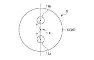
図1〜図4を参照して、本発明のモータの一実施形態について説明する。図1は、本発明の一実施形態に係るモータを概略的に示す縦断面図である。図2は、図1についてモータの出力軸側付近を拡大して示す部分拡大図である。図3は、図1についてモータの反出力軸側付近を拡大して示す部分拡大図である。図4は、図3のA矢示図である。 With reference to FIGS. 1-4, one Embodiment of the motor of this invention is described. FIG. 1 is a longitudinal sectional view schematically showing a motor according to an embodiment of the present invention. FIG. 2 is a partially enlarged view showing the vicinity of the output shaft side of the motor in FIG. FIG. 3 is a partially enlarged view showing the vicinity of the counter-output shaft side of the motor in FIG. FIG. 4 is an arrow A view of FIG.
本実施形態のモータ10は、主な構成として、ロータ20(回転子)と、ステータ30(固定子)と、前部ハウジング40と、後部ハウジング60と、出力軸側軸受11と、反出力軸側軸受12と、一対の管路16,16と、を備える。
The
ロータ20は、出力軸側軸受11と反出力軸側軸受12とによって支えられている。詳細には、ロータ20は、回転軸13を備え、回転軸13は、出力軸側軸受11及び反出力軸側軸受12によって、両端部を支持され、且つ、回転軸線X回りに回転可能に支持される。ロータ20は、回転軸線X軸周りに回転軸13と一体的に回転する。
The
回転軸13は、回転軸13に対しての出力軸側軸受11側の方向(以下、「出力軸側」ともいう)の端部に位置する前方端13aと、回転軸13に対しての反出力軸側軸受12側の方向(以下、「反出力軸側」ともいう)の端部に位置する後方端13bと、を有する。後方端13bには、回転軸13の回転位置及び回転速度等を検出するエンコーダ14が取付けられている。
The
ステータ30は、ロータ20を囲う部材である。詳細には、ステータ30は、ロータ20を包囲するように回転軸線Xに沿って延在する概ね円筒形状の部材である。ステータ30は、積層された多数の電磁鋼板からなるステータコア31と、ステータコア31の内周面に形成される突出部(図示せず)に巻回された巻線32と、を備えている。
The
ステータコア31は、出力軸側軸受11側の端部に位置する前端面31aと、反出力軸側軸受12側の端部に位置する後端面31bと、を有する。
The
巻線32は、樹脂等によってステータコア31に固定されている。巻線32は、ステータコア31の両端から突出するように回転軸線Xに沿って延在している。巻線32には、端子箱15(後述)から延出されたリード線(図示せず)が接続されている。巻線32は、リード線を介して供給される電流によって回転磁界を発生させる。ロータ20は、ステータ30によって発生される回転磁界に従って、回転軸13と一体的に回転するようになっている。
前部ハウジング40は出力軸側軸受11を支える。後部ハウジング60は反出力軸側軸受12を支える。
前部ハウジング40は、前部ハウジング部品41と、前方カバー45とを有する。また、後部ハウジング60は、後部ハウジング部品42と、支持環43と、後方カバー44と、中間カバー46と、ファン47と、を有する。
The
The
前部ハウジング部品41及び後部ハウジング部品42は、ステータコア31から突出する巻線32を包囲している。
The
前部ハウジング部品41は、ステータコア31の前端面31aにネジ留めされている。前部ハウジング部品41は、出力軸側軸受11を支持している。前部ハウジング部品41は、ステータコア31の前端面31aから回転軸13の前方端13aに向かって延在しており、回転軸13の一部及び出力軸側軸受11を包囲している。また、前部ハウジング部品41には、概ね円環形状を有する前方カバー45が取付けられている。
The
前方カバー45は、回転軸13に向かって半径方向内側に突出している。回転軸13の前方端13aは、前部ハウジング部品41及び前方カバー45から突出している。
前部ハウジング部品41及び前方カバー45から突出した回転軸13の前方端13aは、例えば工作機械の主軸に直接的に又は間接的に連結される出力軸として作用する。
The
The
後部ハウジング部品42は、ステータコア31の後端面31bにネジ留めされている。後部ハウジング部品42は、ステータコア31の後端面31bから回転軸13の後方端13bに向かって延在しており、回転軸13の一部及び反出力軸側軸受12を包囲している。
The
支持環43は、後部ハウジング部品42にネジ留めされている。支持環43は、反出力軸側軸受12を支持している。
後方カバー44は、後部ハウジング部品42に取付けられている。後方カバー44は、後部ハウジング部品42から突出する回転軸13の後方端13bを包囲している。
端子箱15は、内部空間を有する部材であり、後部ハウジング部品42に連結されている。
The
The
The terminal box 15 is a member having an internal space and is connected to the
中間カバー46は、支持環43にネジ留めされている。中間カバー46は、支持環43と後方カバー44との間に配置される。
ファン47は、後方カバー44の内面側に固定されている。ファン47は、回転軸13と軸心を一致させて配置される。
The
The
出力軸側軸受11は、回転軸13の前方端13aの近傍に配置されている。出力軸側軸受11は、回転軸13の前方端13aを支持する。出力軸側軸受11は、内部に、粘度の高い潤滑剤を保持する。出力軸側軸受11は、図2に示すように、出力軸側内環111と、出力軸側外環112と、出力軸側転動体113と、一対の貫通孔114a,114bと、を備える。
The output shaft side bearing 11 is disposed in the vicinity of the
出力軸側内環111は、回転軸13の前方端13aに係止可能な径で環状に形成される。出力軸側内環111の内周面は、前方端13aの外周面に係止される。出力軸側内環111は、周方向に沿って延びる溝を外周面に有する。
The output shaft side inner ring 111 is formed in an annular shape with a diameter that can be locked to the
出力軸側外環112は、出力軸側内環111の径よりも大きな内径をもつ環状に形成される。出力軸側外環112は、内周面を出力軸側内環111の外周面に対向するように配置される。即ち、出力軸側外環112は、出力軸側内環111と合わせて二重環となるように配置される。出力軸側外環112は、周方向に沿って延びる溝を内周面に有する。また、出力軸側外環112は、出力軸側内環111との間に潤滑剤を保持する。
The output shaft side
出力軸側転動体113は、球体であり、出力軸側内環111及び出力軸側外環112に設けられる溝によって自転及び公転可能に支持される。出力軸側転動体113は、溝に沿って複数設けられる。出力軸側転動体113は、自転及び公転することにより、出力軸側外環112に対する出力軸側内環111の回転を可能にする。
The output shaft
一対の貫通孔114a,114bのそれぞれは、出力軸側内環111の内周面から外周面へ貫通する。一対の貫通孔114a,114bのそれぞれは、回転軸13の軸(回転軸線X)に対して対称となる位置に配置される。また、一方の貫通孔114aは、出力軸側内環111の軸方向中央位置よりも前方端13aよりに配置される。そして、他方の貫通孔114bは、出力軸側内環111の軸方向中央位置よりも後方端13bよりに配置される。
Each of the pair of through
反出力軸側軸受12は、回転軸13の後方端13bの近傍に配置されている。反出力軸側軸受12は、回転軸13の後方端13bを支持する。反出力軸側軸受12は、内部に、粘度の高い潤滑剤を保持する。出力軸側軸受11は、図3に示すように、反出力軸側内環121と、反出力軸側外環122と、反出力軸側転動体123と、一対の貫通孔124a,124bと、を備える。
The non-output shaft side bearing 12 is disposed in the vicinity of the rear end 13 b of the
反出力軸側内環121は、回転軸13の後方端13bに係止可能な径で環状に形成される。反出力軸側内環121の内周面は、後方端13bの外周面に係止される。反出力軸側内環121は、周方向に沿って延びる溝を外周面に有する。
The non-output shaft side
反出力軸側外環122は、反出力軸側内環121の径よりも大きな内径をもつ環状に形成される。反出力軸側外環122は、内周面を反出力軸側内環121の外周面に対向するように配置される。即ち、反出力軸側外環122は、反出力軸側内環121と合わせて二重環となるように配置される。反出力軸側外環122は、周方向に沿って延びる溝を内周面に有する。また、反出力軸側外環122は、反出力軸側内環121との間に潤滑剤を保持する。
The counter-output shaft side
反出力軸側転動体123は、球体であり、反出力軸側内環121及び反出力軸側外環122に設けられる溝によって自転及び公転可能に支持される。反出力軸側転動体123は、溝に沿って複数設けられる。反出力軸側転動体123は、自転及び公転することにより、反出力軸側外環122に対する反出力軸側内環121の回転を可能にする。
The non-output shaft
一対の貫通孔124a,124bのそれぞれは、反出力軸側内環121の内周面から外周面へ貫通する。一対の貫通孔124a,124bのそれぞれは、回転軸13の軸(回転軸線X)に対して対称となる位置に配置される。また、一方の貫通孔124aは、反出力軸側内環121の軸方向中央位置よりも前方端13aよりに配置される。そして、他方の貫通孔124bは、反出力軸側内環121の軸方向中央位置よりも後方端13bよりに配置される。
Each of the pair of through
一対の管路16a,16bのそれぞれは、ロータ20の後部ハウジング60側の面に開口17a,17bを有し、ロータ20の内部に設けられる。具体的に、一対の管路16a,16bのそれぞれは、回転軸13の後部ハウジング60側の面に開口17a,17bを有し、回転軸13の内部に設けられる。一対の管路16a,16bは、出力軸側軸受11及び反出力軸側軸受12の少なくとも一方へ共に連通し、潤滑液を流通可能になっている。一対の管路16a,16bのそれぞれは、ロータ20の軸に対して対称となる位置に配置される。本実施形態において、一対の管路16a,16bのそれぞれは、回転軸13の内部で分岐し、出力軸側軸受11及び反出力軸側軸受12の両方に連通する。
Each of the pair of
また、一対の管路16a,16bのそれぞれの開口17a,17bは、図4に示すように、ロータ20(回転軸13)の後部ハウジング60側の端面Sに設けられる。そして、一対の管路16a,16bのそれぞれの開口17a,17bは、回転軸13の軸(回転軸線X)に対して対称となる位置に配置される。具体的には、一対の管路16a,16bの開口17a,17bのそれぞれは、回転軸13の軸(回転軸線X)に対して対称であり、軸(回転軸線X)に対して距離Tだけ離間して配置される。また、一対の管路16a,16bのそれぞれの開口17a,17bは、通常時(潤滑剤を交換しない間)には、栓(図示せず)により閉鎖される。
Moreover, each
一方の管路16aは、回転軸13の後部ハウジング60側の端面Sに設けられる開口17aから、回転軸13の軸心に沿って直線状に延びる。一方の管路16aは、分岐して、出力軸側軸受11の一対の貫通孔114a,114bの一方と、反出力軸側軸受12の一対の貫通孔124a,124bの一方とに連通する。本実施形態では、一方の管路16aは、いずれも前方端13a側よりに位置する貫通孔114a,124aに連通する。これにより、一方の管路16aは、例えば、潤滑剤の供給路として機能する。
One
他方の管路16bは、回転軸13の後部ハウジング60側の端面Sに設けられる開口17bから、回転軸13の軸心に沿って直線状に延びる。他方の管路16bは、分岐して、出力軸側軸受11の一対の貫通孔114a,114bの他方と、反出力軸側軸受12の一対の貫通孔124a,124bの他方とに連通する。本実施形態では、他方の管路16bは、いずれも後方端13bよりに位置する貫通孔114b,124bに連通する。これにより、他方の管路16は、例えば、潤滑剤の排出路として機能する。
The
以上のようなモータ10の潤滑剤の交換は、以下のように行われる。
まず、ロータ20(回転軸13)の回転が停止される。そして、後方カバー44及び中間カバー46が取り外される。これにより、ロータ20(回転軸13)の後部ハウジング60側が、外部に露出する。即ち、ロータ20(回転軸13)の後部ハウジング60側の端面Sが、外部に露出する。従って、一対の管路16a,16bの開口17a,17bが、外部に露出する。
The replacement of the lubricant in the
First, the rotation of the rotor 20 (rotating shaft 13) is stopped. Then, the
次に、一対の管路16a,16bの開口17a,17bのそれぞれから、栓(図示せず)が取り外される。そして、一方の管路16aの開口17aから、潤滑剤が供給されることにより、一方の貫通孔114a,124aのそれぞれを介して、出力軸側軸受11及び反出力軸側軸受12の内部に潤滑剤が注入される。潤滑剤が注入されることにより、出力軸側軸受11及び反出力軸側軸受12に既に保持されている潤滑剤(劣化した潤滑剤)が、注入された潤滑剤とほぼ同量分、他方の貫通孔114b,124bのそれぞれを介して排出される。排出された潤滑剤は、他方の管路16bを流通して、開口17bから排出される。
Next, a plug (not shown) is removed from each of the
ここで、一対の貫通孔114a,114b及び一対の貫通孔124a,124bがロータ20(回転軸13)の軸(回転軸線X)に対して対称である。また、一方の貫通孔114a,124a(供給側)が前方端13aよりに位置し、他方の貫通孔124a,124b(排出側)が後方端13bよりに位置する。即ち、一対の貫通孔114a,114bについて、一方の貫通孔114aから他方の貫通孔114bに至る経路が最も遠くなるように配置されている。また、一対の貫通孔124a,124bについて、一方の貫通孔124aから他方の貫通孔124bに至る経路が最も遠くなるように配置されている。これにより、出力軸側軸受11及び反出力軸側軸受12の内部に既に保持されている潤滑剤が優先的に排出される。
Here, the pair of through
そして、十分な量の潤滑剤が供給されることにより、出力軸側軸受11及び反出力軸側軸受12に保持されている潤滑剤の全てが新たな潤滑剤に交換される。潤滑剤の交換が終了した後、一対の管路16a,16bの開口17a,17bは、栓(図示せず)により再び閉鎖される。そして、中間カバー46及び後方カバー44が再び取り付けられることにより、ロータ20(回転軸13)の後部ハウジング60側の端面Sが露出しなくなる。
Then, by supplying a sufficient amount of lubricant, all of the lubricant held in the output shaft side bearing 11 and the non-output shaft side bearing 12 is replaced with a new lubricant. After the replacement of the lubricant is completed, the
本実施形態のモータ10によれば、例えば以下の効果が奏される。
本実施形態のモータを、出力軸側軸受11と反出力軸側軸受12とによって支えられたロータ20と、出力軸側軸受11を支える前部ハウジング40と、反出力軸側軸受12を支える後部ハウジング60と、前部ハウジング40及び後部ハウジング60が両端に取り付けられ、ロータ20を囲うステータ30と、ロータ20の後部ハウジング60側の面に開口17a,17bを有し、ロータ20の内部に設けられる一対の管路16a,16bであって、出力軸側軸受11及び反出力軸側軸受12の少なくとも一方へ共に連通する一対の管路16a,16bと、により構成した。従って、出力軸側軸受11及び反出力軸側軸受12が前部ハウジング40及び後部ハウジング60により囲われていたとしても、大掛かりに分解することなく開口17a,17bを露出させることができる。そして、一方の開口17aから潤滑剤を供給することにより、一対の管路16a,16bを介して、他方の開口17bから劣化した潤滑剤を排出することができるので、潤滑剤の交換を容易にすることができる。
According to the
The motor of this embodiment includes a
また、開口17a,17bを、ロータ20の後部ハウジング60側の端面に設けた。従って、ロータ20を露出させるために外す部分をより少なくすることができ、潤滑剤の交換をより容易にすることができる。
The
また、一対の管路16a,16bを、ロータ20の軸(回転軸線X)に対して対称となる位置に配置した。従って、出力軸側軸受11及び反出力軸側軸受12の少なくとも一方において、潤滑剤の供給位置と、潤滑剤の排出位置とはロータ20の軸(回転軸線X)に対して対称となる位置に配置される。即ち、潤滑剤の供給位置と、潤滑剤の排出位置とが最も遠くなる位置に配置される。これにより、新たな潤滑剤の供給が供給位置から開始されると、供給位置から最も遠い位置の使用済み潤滑剤から排出が開始される。そして、使用済みの全ての潤滑剤が新たな潤滑剤に交換されるまで、使用済み潤滑剤を優先的に排出させることができる。このように、潤滑剤の交換の効率を向上させることができる。
Further, the pair of
本発明は、上記実施形態に限定されるものではなく、種々の変更及び変形が可能である。例えば、上記実施形態において、一対の管路16a,16bの開口17a,17bをロータ20(回転軸13)の後部ハウジング60側の端面に設けるとしたが、これに限定されない。一対の管路16a,16bの開口17a,17bは、反出力軸側軸受12に支持される周面よりも後部ハウジング60側の周面に設けられてもよい。
The present invention is not limited to the above embodiment, and various changes and modifications can be made. For example, in the above embodiment, the
また、上記実施形態において、一対の管路16a,16bのそれぞれは、分岐して、出力軸側軸受11及び反出力軸側軸受12の両方に連通するとしたが、これに限定されない。例えば、一対の管路16a,16bのそれぞれは、出力軸側軸受11及び反出力軸側軸受12のいずれか一方に共に連通するようになっていてもよい。また、さらに一対の管路(図示せず)がロータ20の内部に設けられ、一対の管路16a,16bと併せて、それぞれの管路が出力軸側軸受11の一対の貫通孔114a,114b、及び、反出力軸側軸受12の一対の貫通孔124a,124bに連通してもよい。このとき、それぞれの管路の開口は、端面Sの径方向に並ぶことが好適である。出力軸側軸受11の供給管としての管路の開口と、排出側としての管路の開口は、端面Sにおいて、軸(回転軸線X)に対して対称であり、軸(回転軸線X)から等距離であるのが好適である。反出力軸側軸受12の供給管としての管路の開口と、排出側としての管路の開口は、端面Sにおいて、軸(回転軸線X)に対して対称であり、軸(回転軸線X)から等距離であるのが好適である。
Moreover, in the said embodiment, although each of a pair of
また、上記実施形態において、一対の貫通孔114a,114bのうち、前方端13aよりに位置する貫通孔114aを供給側、後方端13bよりに位置する貫通孔114bを排出側としたが、逆であってもよい。また、例えば、出力軸側軸受11では、前方端13aよりに位置する貫通孔114aが供給側であり、反出力軸側軸受12では、後方端13bよりに位置する貫通孔124bが供給側であるように、互い違いになっていてもよい。一対の管路16a,16bのそれぞれは、一方が供給側、他方が排出側となっていれば、上記効果を奏する限り、種々の組み合わせで構成可能である。
Moreover, in the said embodiment, although the through-
10 モータ
11 出力軸側軸受
12 反出力軸側軸受
16 管路
17 開口
20 ロータ
30 ステータ
40 前部ハウジング
60 後部ハウジング
S 端面
DESCRIPTION OF
Claims (3)
前記出力軸側軸受を支える前部ハウジングと、
前記反出力軸側軸受を支える後部ハウジングと、
前記前部ハウジング及び前記後部ハウジングが両端に取り付けられ、前記ロータを囲うステータと、
前記ロータの前記後部ハウジング側の面に開口を有し、前記ロータの内部に設けられる一対の管路であって、前記ロータの軸に対して対称となる位置に配置され、前記出力軸側軸受及び前記反出力軸側軸受の少なくとも一方へ共に連通し、潤滑液を流通可能な一対の管路と、
を備え、
前記出力軸側軸受は、
前記ロータの前方端に係止可能な出力軸側内環と、
前記出力軸側内環の内周面から外周面に貫通し、一対の前記管路のそれぞれに連通する一対の貫通孔と、
を備え、
一方の貫通孔は、前記出力軸側内環の軸方向中央位置よりも前方端寄りに配置され、
他方の貫通孔は、前記出力軸側内環の軸方向中央位置よりも後方端寄りに配置されることを特徴とするモータ。 A rotor supported by the output shaft side bearing and the non-output shaft side bearing;
A front housing for supporting the output shaft side bearing;
A rear housing for supporting the non-output shaft side bearing;
The front housing and the rear housing are attached to both ends, and the stator surrounds the rotor;
The output shaft side bearing is a pair of pipes provided in the rotor having an opening on a surface on the rear housing side of the rotor, and arranged at positions symmetrical with respect to the axis of the rotor. And a pair of conduits that communicate with at least one of the counter-output shaft side bearings and allow the lubricating liquid to flow therethrough,
Equipped with a,
The output shaft side bearing is
An output shaft side inner ring that can be locked to the front end of the rotor;
A pair of through holes penetrating from the inner peripheral surface of the output shaft side inner ring to the outer peripheral surface and communicating with each of the pair of pipes;
With
One through hole is arranged closer to the front end than the axial center position of the output shaft side inner ring,
The other through hole, the motor characterized by Rukoto disposed rearward end nearer the axial center of the output in the shaft side ring.
Priority Applications (5)
| Application Number | Priority Date | Filing Date | Title |
|---|---|---|---|
| JP2016234237A JP6412089B2 (en) | 2016-12-01 | 2016-12-01 | motor |
| DE102017010966.4A DE102017010966B4 (en) | 2016-12-01 | 2017-11-27 | engine |
| US15/823,660 US10385917B2 (en) | 2016-12-01 | 2017-11-28 | Motor |
| CN201711230639.9A CN108134471B (en) | 2016-12-01 | 2017-11-29 | Motor |
| CN201721629457.4U CN207559735U (en) | 2016-12-01 | 2017-11-29 | Motor |
Applications Claiming Priority (1)
| Application Number | Priority Date | Filing Date | Title |
|---|---|---|---|
| JP2016234237A JP6412089B2 (en) | 2016-12-01 | 2016-12-01 | motor |
Publications (2)
| Publication Number | Publication Date |
|---|---|
| JP2018093601A JP2018093601A (en) | 2018-06-14 |
| JP6412089B2 true JP6412089B2 (en) | 2018-10-24 |
Family
ID=62163882
Family Applications (1)
| Application Number | Title | Priority Date | Filing Date |
|---|---|---|---|
| JP2016234237A Active JP6412089B2 (en) | 2016-12-01 | 2016-12-01 | motor |
Country Status (4)
| Country | Link |
|---|---|
| US (1) | US10385917B2 (en) |
| JP (1) | JP6412089B2 (en) |
| CN (2) | CN108134471B (en) |
| DE (1) | DE102017010966B4 (en) |
Family Cites Families (18)
| Publication number | Priority date | Publication date | Assignee | Title |
|---|---|---|---|---|
| JP2524077Y2 (en) * | 1990-09-14 | 1997-01-29 | 神鋼電機株式会社 | Bearing lubrication device for outer rotor type motor |
| US5106209A (en) * | 1991-08-07 | 1992-04-21 | General Electric Company | Multi-plane lubricated bearing assembly |
| JP3625884B2 (en) * | 1994-12-05 | 2005-03-02 | 日本電産株式会社 | Motor with hydrodynamic bearing |
| JP3000344B2 (en) * | 1996-08-06 | 2000-01-17 | 株式会社久保田鉄工所 | Water pump and manufacturing method thereof |
| US6727609B2 (en) * | 2001-08-08 | 2004-04-27 | Hamilton Sundstrand Corporation | Cooling of a rotor for a rotary electric machine |
| JP3925145B2 (en) * | 2001-10-12 | 2007-06-06 | 日産自動車株式会社 | Bearing lubrication structure of rotating shaft |
| JP4096858B2 (en) * | 2002-10-23 | 2008-06-04 | 日産自動車株式会社 | Cooling device for electric motor for vehicle |
| EP1655259B1 (en) | 2003-08-05 | 2011-06-15 | Mitsubishi Denki Kabushiki Kaisha | Hoist for elevator |
| JP4680584B2 (en) * | 2004-12-24 | 2011-05-11 | 住友電気工業株式会社 | Superconducting motor cooling structure |
| EP1984602B1 (en) * | 2006-02-02 | 2015-10-21 | Frank Eckert | Organic rankine cycle (orc) turbogenerator |
| US7834492B2 (en) * | 2006-07-31 | 2010-11-16 | Caterpillar Inc | Electric machine having a liquid-cooled rotor |
| JP4363479B2 (en) * | 2007-11-09 | 2009-11-11 | トヨタ自動車株式会社 | Rotating electric machine and driving device |
| DE102009051002A1 (en) * | 2009-10-28 | 2011-05-05 | Schaeffler Technologies Gmbh & Co. Kg | Drive unit for motor vehicles with an electric motor |
| US8928195B2 (en) * | 2010-04-23 | 2015-01-06 | Ihi Corporation | Rotary machine |
| DE102012203697A1 (en) * | 2012-03-08 | 2013-09-12 | Siemens Aktiengesellschaft | Electric machine with a rotor for cooling the electric machine |
| JP6229331B2 (en) * | 2013-07-02 | 2017-11-15 | 日本電産株式会社 | motor |
| US9929614B2 (en) | 2013-07-02 | 2018-03-27 | Nidec Corporation | Motor with integrated slot liner and bobbin with guides for conductor coils |
| DE102013226851A1 (en) * | 2013-12-20 | 2015-06-25 | Siemens Aktiengesellschaft | Rotary dynamoelectric machine with a cooling system |
-
2016
- 2016-12-01 JP JP2016234237A patent/JP6412089B2/en active Active
-
2017
- 2017-11-27 DE DE102017010966.4A patent/DE102017010966B4/en active Active
- 2017-11-28 US US15/823,660 patent/US10385917B2/en active Active
- 2017-11-29 CN CN201711230639.9A patent/CN108134471B/en active Active
- 2017-11-29 CN CN201721629457.4U patent/CN207559735U/en active Active
Also Published As
| Publication number | Publication date |
|---|---|
| DE102017010966A1 (en) | 2018-06-07 |
| DE102017010966B4 (en) | 2021-03-25 |
| US10385917B2 (en) | 2019-08-20 |
| CN207559735U (en) | 2018-06-29 |
| CN108134471B (en) | 2019-07-09 |
| JP2018093601A (en) | 2018-06-14 |
| CN108134471A (en) | 2018-06-08 |
| US20180156272A1 (en) | 2018-06-07 |
Similar Documents
| Publication | Publication Date | Title |
|---|---|---|
| JP6118633B2 (en) | Electric motor | |
| WO2016067352A1 (en) | Dynamo-electric machine | |
| JP2012105487A (en) | Cooling device for electric motor | |
| JP2010263696A (en) | Motor cooling structure | |
| CN101619724A (en) | Pump apparatus | |
| JP2016146704A (en) | Rotary electric machine | |
| CN107979208B (en) | Electric motor | |
| JP2015104214A (en) | Rotary electric machine | |
| JP6397867B2 (en) | Rotating electric machine | |
| JP5589419B2 (en) | Bearing device and spindle device for machine tool | |
| JP2020145782A (en) | Rotor and rotary electric machine | |
| JP6382913B2 (en) | Electric motor with labyrinth | |
| JP5776753B2 (en) | Bearing device and spindle device for machine tool | |
| JP2014064433A (en) | Rotor shaft of rotary electric machine | |
| JP6412089B2 (en) | motor | |
| JP2018068087A (en) | Rotary electric machine and manufacturing method of rotary electric machine | |
| JP2019154156A (en) | Outer rotor type rotary electric machine | |
| JP6332876B2 (en) | Rotating electric machine rotor and method of manufacturing rotating electric machine rotor | |
| JP5730740B2 (en) | Rotating electric machine | |
| JP6825227B2 (en) | Rotating machine | |
| JP2016001974A (en) | Multi-gap rotary electric machine | |
| JP2015113787A (en) | Scroll type fluid machinery | |
| JP7131220B2 (en) | vehicle power transmission | |
| JP2019004557A (en) | Motor generator device | |
| JP2014212586A (en) | Rotary electric machine |
Legal Events
| Date | Code | Title | Description |
|---|---|---|---|
| A975 | Report on accelerated examination |
Free format text: JAPANESE INTERMEDIATE CODE: A971005 Effective date: 20180425 |
|
| A131 | Notification of reasons for refusal |
Free format text: JAPANESE INTERMEDIATE CODE: A131 Effective date: 20180508 |
|
| A521 | Request for written amendment filed |
Free format text: JAPANESE INTERMEDIATE CODE: A523 Effective date: 20180704 |
|
| TRDD | Decision of grant or rejection written | ||
| A01 | Written decision to grant a patent or to grant a registration (utility model) |
Free format text: JAPANESE INTERMEDIATE CODE: A01 Effective date: 20180904 |
|
| A61 | First payment of annual fees (during grant procedure) |
Free format text: JAPANESE INTERMEDIATE CODE: A61 Effective date: 20180927 |
|
| R150 | Certificate of patent or registration of utility model |
Ref document number: 6412089 Country of ref document: JP Free format text: JAPANESE INTERMEDIATE CODE: R150 |