JP6408327B2 - Friction type continuously variable transmission - Google Patents
Friction type continuously variable transmission Download PDFInfo
- Publication number
- JP6408327B2 JP6408327B2 JP2014200991A JP2014200991A JP6408327B2 JP 6408327 B2 JP6408327 B2 JP 6408327B2 JP 2014200991 A JP2014200991 A JP 2014200991A JP 2014200991 A JP2014200991 A JP 2014200991A JP 6408327 B2 JP6408327 B2 JP 6408327B2
- Authority
- JP
- Japan
- Prior art keywords
- rolling element
- shaft
- planetary roller
- continuously variable
- variable transmission
- Prior art date
- Legal status (The legal status is an assumption and is not a legal conclusion. Google has not performed a legal analysis and makes no representation as to the accuracy of the status listed.)
- Active
Links
- 230000005540 biological transmission Effects 0.000 title claims description 104
- 238000005096 rolling process Methods 0.000 claims description 427
- 230000002093 peripheral effect Effects 0.000 claims description 17
- 230000007423 decrease Effects 0.000 description 3
- 238000010586 diagram Methods 0.000 description 3
- 230000007812 deficiency Effects 0.000 description 2
- 238000004519 manufacturing process Methods 0.000 description 2
- 238000012795 verification Methods 0.000 description 1
Images


Classifications
-
- F—MECHANICAL ENGINEERING; LIGHTING; HEATING; WEAPONS; BLASTING
- F16—ENGINEERING ELEMENTS AND UNITS; GENERAL MEASURES FOR PRODUCING AND MAINTAINING EFFECTIVE FUNCTIONING OF MACHINES OR INSTALLATIONS; THERMAL INSULATION IN GENERAL
- F16H—GEARING
- F16H15/00—Gearings for conveying rotary motion with variable gear ratio, or for reversing rotary motion, by friction between rotary members
- F16H15/48—Gearings for conveying rotary motion with variable gear ratio, or for reversing rotary motion, by friction between rotary members with members having orbital motion
- F16H15/50—Gearings providing a continuous range of gear ratios
- F16H15/52—Gearings providing a continuous range of gear ratios in which a member of uniform effective diameter mounted on a shaft may co-operate with different parts of another member
-
- F—MECHANICAL ENGINEERING; LIGHTING; HEATING; WEAPONS; BLASTING
- F16—ENGINEERING ELEMENTS AND UNITS; GENERAL MEASURES FOR PRODUCING AND MAINTAINING EFFECTIVE FUNCTIONING OF MACHINES OR INSTALLATIONS; THERMAL INSULATION IN GENERAL
- F16H—GEARING
- F16H15/00—Gearings for conveying rotary motion with variable gear ratio, or for reversing rotary motion, by friction between rotary members
- F16H15/02—Gearings for conveying rotary motion with variable gear ratio, or for reversing rotary motion, by friction between rotary members without members having orbital motion
- F16H15/04—Gearings providing a continuous range of gear ratios
-
- F—MECHANICAL ENGINEERING; LIGHTING; HEATING; WEAPONS; BLASTING
- F16—ENGINEERING ELEMENTS AND UNITS; GENERAL MEASURES FOR PRODUCING AND MAINTAINING EFFECTIVE FUNCTIONING OF MACHINES OR INSTALLATIONS; THERMAL INSULATION IN GENERAL
- F16H—GEARING
- F16H13/00—Gearing for conveying rotary motion with constant gear ratio by friction between rotary members
- F16H13/06—Gearing for conveying rotary motion with constant gear ratio by friction between rotary members with members having orbital motion
- F16H13/08—Gearing for conveying rotary motion with constant gear ratio by friction between rotary members with members having orbital motion with balls or with rollers acting in a similar manner
-
- F—MECHANICAL ENGINEERING; LIGHTING; HEATING; WEAPONS; BLASTING
- F16—ENGINEERING ELEMENTS AND UNITS; GENERAL MEASURES FOR PRODUCING AND MAINTAINING EFFECTIVE FUNCTIONING OF MACHINES OR INSTALLATIONS; THERMAL INSULATION IN GENERAL
- F16H—GEARING
- F16H15/00—Gearings for conveying rotary motion with variable gear ratio, or for reversing rotary motion, by friction between rotary members
- F16H15/48—Gearings for conveying rotary motion with variable gear ratio, or for reversing rotary motion, by friction between rotary members with members having orbital motion
- F16H15/50—Gearings providing a continuous range of gear ratios
- F16H15/506—Gearings providing a continuous range of gear ratios in which two members of non-uniform effective diameter directly co-operate with one another
Landscapes
- Engineering & Computer Science (AREA)
- General Engineering & Computer Science (AREA)
- Mechanical Engineering (AREA)
- Friction Gearing (AREA)
Description
本発明は、摩擦式無段変速機に係る。 The present invention relates to a friction type continuously variable transmission.
複数の遊星ローラを有する無段変速機が従来から知られている(例えば、特許文献1)。特許文献1に記載された無段変速機は、シャフト(105)に直交する平面上に複数の球(101)が分散されている。各球(101)は、片側に入力ディスクが接触し、反対側に出力ディスクが接触し、球(101)を介して、入力ディスク(110)から出力ディスク(134)へトルクが伝達される。 A continuously variable transmission having a plurality of planetary rollers is conventionally known (for example, Patent Document 1). In the continuously variable transmission described in Patent Document 1, a plurality of spheres (101) are dispersed on a plane orthogonal to the shaft (105). In each sphere (101), the input disk contacts one side and the output disk contacts the other side, and torque is transmitted from the input disk (110) to the output disk (134) via the sphere (101).
各球(101)は、傾斜可変の球軸(102)を有し、シャフト(105)に対する球軸(102)の傾斜角を変化させることにより、入力ディスク(110)及び出力ディスク(134)の速度比を調整することができる。球(101)は、一対のアーム(103)により傾斜可変に支持され、球軸(102)の両端を支持する一対のアーム(103)は、ともに変速ローラ(126)に取り付けられている。このため、変速ローラ(126)をシャフト(105)に沿って変位させれば、シャフト(105)に対する球軸(102)の傾斜角が変化し、入力ディスク(110)に対する出力ディスク(134)の速度比が変化する。 Each sphere (101) has a variable tilting spherical axis (102), and by changing the inclination angle of the spherical axis (102) with respect to the shaft (105), the input disk (110) and the output disk (134) The speed ratio can be adjusted. The sphere (101) is supported by a pair of arms (103) so as to be inclined, and the pair of arms (103) supporting both ends of the sphere axis (102) are both attached to the speed change roller (126). Therefore, if the speed change roller (126) is displaced along the shaft (105), the inclination angle of the spherical axis (102) with respect to the shaft (105) changes, and the output disk (134) with respect to the input disk (110) changes. The speed ratio changes.
このような従来の無段変速機は、変速機構が複雑であるため、部品点数が多くなり、変速機の重量が重くなるという問題があった。また、製造コストを低減することが難しいという問題があった。 Such a conventional continuously variable transmission has a problem that the number of parts increases and the weight of the transmission increases because the speed change mechanism is complicated. In addition, there is a problem that it is difficult to reduce the manufacturing cost.
本発明は、上記事情に鑑みてなされたものであり、摩擦式無段変速機の伝達性能の向上と部品点数の削減を目的とする。 The present invention has been made in view of the above circumstances, and aims to improve the transmission performance and reduce the number of parts of a friction type continuously variable transmission.
本発明による摩擦式無段変速機は、上下方向に延びる主軸を中心とする環状の第1転動体と、前記主軸を中心とする環状の第2転動体と、前記主軸を中心とする環状の第3転動体と、前記主軸の周方向に配置される複数の遊星ローラと、前記遊星ローラを回転可能にそれぞれ支持する複数の支持ピンと、前記主軸を含む断面上において前記支持ピンを傾斜自在に支持する遊星ローラ支持部とを有している。前記遊星ローラは、前記支持ピンを中心とする外周上に円環形状の凹部を有する。前記第1転動体は、前記凹部よりも軸方向下側において、径方向の一方から前記遊星ローラの転動面に接触し、前記第3転動体に対し、軸受を介して相対回転可能に支持される。前記第2転動体は、前記凹部よりも軸方向上側において、径方向の前記一方から前記遊星ローラの転動面に接触し、前記第3転動体に対し、軸受を介して相対回転可能に支持される。前記第3転動体は、径方向の他方から、前記遊星ローラの前記凹部に接触し、前記遊星ローラ支持部に対し、上下方向に相対移動可能に支持される。前記第3転動体は、前記遊星ローラの前記凹部の内面に接触する円弧形状の接触部を有する。前記凹部の内面は、前記主軸を含む断面上において円弧である。前記凹部の断面の曲率半径は、前記第3転動体の前記接触部の曲率半径よりも大きい。
A friction type continuously variable transmission according to the present invention includes an annular first rolling element centered on a main shaft extending in the vertical direction, an annular second rolling element centered on the main shaft, and an annular second rolling element centered on the main shaft. A third rolling element, a plurality of planetary rollers disposed in a circumferential direction of the main shaft, a plurality of support pins for rotatably supporting the planetary roller, and the support pin tiltable on a cross section including the main shaft; And a planetary roller support portion for supporting. The planetary roller has an annular recess on the outer periphery centered on the support pin. The first rolling element is in contact with the rolling surface of the planetary roller from one of the radial directions on the lower side in the axial direction than the recess , and is supported so as to be relatively rotatable with respect to the third rolling element via a bearing. Is done. The second rolling element comes into contact with the rolling surface of the planetary roller from the one side in the radial direction above the concave portion in the axial direction, and is supported so as to be relatively rotatable with respect to the third rolling element via a bearing. Is done. The third rolling element comes into contact with the concave portion of the planetary roller from the other radial direction, and is supported so as to be relatively movable in the vertical direction with respect to the planetary roller support portion. The third rolling element has an arc-shaped contact portion that contacts an inner surface of the concave portion of the planetary roller. The inner surface of the recess is an arc on a cross section including the main axis. The radius of curvature of the cross section of the recess is larger than the radius of curvature of the contact portion of the third rolling element.
このような構成を採用することにより、第3転動体を上下方向に移動させると、支持ピンが傾き、ともに遊星ローラの転動面に接触する第1転動体に対する第2転動体の回転数の比が変化する。このため、複雑な機構を採用することなく、変速比を連続して変化させることができる。 By adopting such a configuration, when the third rolling element is moved in the vertical direction, the support pin is inclined, and the rotational speed of the second rolling element with respect to the first rolling element that contacts the rolling surface of the planetary roller is determined. The ratio changes. For this reason, a gear ratio can be changed continuously, without employ | adopting a complicated mechanism.
本発明によれば、複雑な機構を採用することなく、速度比を連続して変化させることができ、摩擦式無段変速機の部品点数を削減することができる。 According to the present invention, the speed ratio can be continuously changed without employing a complicated mechanism, and the number of parts of the friction type continuously variable transmission can be reduced.
以下、本発明の実施の形態について、図面を参照して説明する。本明細書では、便宜上、無段変速機の主軸Jの方向を上下方向として説明するが、本発明による無段変速機の使用時における姿勢を限定するものではない。また、主軸Jの方向を単に「軸方向」と呼び、主軸Jを中心とする径方向及び周方向を単に「径方向」及び「周方向」と呼ぶことにする。 Embodiments of the present invention will be described below with reference to the drawings. In the present specification, for the sake of convenience, the direction of the main shaft J of the continuously variable transmission is described as the vertical direction, but the posture of the continuously variable transmission according to the present invention is not limited. Further, the direction of the main axis J is simply referred to as “axial direction”, and the radial direction and the circumferential direction around the main axis J are simply referred to as “radial direction” and “circumferential direction”.
実施の形態1.
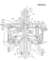
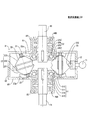
図1は、本発明の実施の形態1による無段変速機100の一構成例を示した図であり、主軸Jを含む平面で切断したときの断面が示されている。なお、図1は、説明の便宜上、主軸Jを挟んで左側と右側に、それぞれ異なる動作状態の断面が示されている。
Embodiment 1 FIG.
FIG. 1 is a view showing a configuration example of a continuously variable transmission 100 according to Embodiment 1 of the present invention, and shows a cross section when cut along a plane including a main shaft J. In FIG. 1, for convenience of explanation, cross sections in different operating states are shown on the left side and the right side across the main axis J.
無段変速機100は、自転車用の摩擦式無段変速機であり、変速機能を有するハブとして、自転車の車輪に組み込まれる。なお、本発明に係る無段変速機は、自転車用に限定されず、また、ハブとして車輪に組み込まれるものにも限定されない。 The continuously variable transmission 100 is a friction type continuously variable transmission for a bicycle, and is incorporated in a bicycle wheel as a hub having a speed change function. The continuously variable transmission according to the present invention is not limited to a bicycle, and is not limited to a hub incorporated in a wheel as a hub.
無段変速機100は、シャフト10、調整ロッド12、遊星ローラ20、第1転動体31、第2転動体32及び第3転動体33を備えている。以下、これらの各部品について詳しく説明する。
The continuously variable transmission 100 includes a
[シャフト10]
シャフト10は、軸方向(上下方向)に延びる略円柱形状の部材である。シャフト10は、主軸Jと一致する中心軸を有し、両端が一対のドロップアウト11によって支持される。ドロップアウト11は、自転車フレームに設けられたハブ取付部である。また、シャフト10内には、調整ロッド12を収容するための軸方向に延びる中空部13が設けられている。例えば、シャフト10内において軸方向に延びる円柱形状の空間が中空部13として形成される。この場合、シャフト10は、軸方向の少なくとも一部において円筒形状となる。
[Shaft 10]
The
[調整ロッド12]
調整ロッド12は、軸方向に延びる部材であり、例えば、略円柱形状を有し、シャフト10の中空部13内に配置されている。第3転動体33は、ピン33Pを介して、調整ロッド12に支持され、調整ロッド12とともに軸方向に移動する。このため、調整ロッド12は、シャフト10に対し、相対回転することはできないが、軸方向に相対移動することができる。
[Adjusting rod 12]
The
[遊星ローラ20]
遊星ローラ20は、主軸Jを中心とする周方向に配置される転動体である。無段変速機100は、複数の遊星ローラ20を有し、これらの遊星ローラ20は、主軸Jと直交する平面内において周方向に等間隔で配列される。各遊星ローラ20は、同一形状の2つの円錐台の底面を接合したダブルコーン形状の接合部の外周に凹部230を形成した形状を有する。
[Planetary roller 20]
The
支持ピン21は、遊星ローラ20を回転可能に支持する。また、支持ピン21は、遊星ローラ支持部22により、主軸Jを含む平面内において傾斜自在に支持される。
The
遊星ローラ支持部22は、支持ピン21を傾斜自在に支持する。また、遊星ローラ支持部22は、シャフト10に固定されている。遊星ローラ支持部22は、支持ピン21の両端をそれぞれ支持する一対のガイド部22gを有する。一対のガイド部22gは、例えば、主軸Jを含む平面上において同心に配置された円弧形状を有し、支持ピン21の両端は、これらのガイド部22gに沿って移動自在に支持される。
The planetary
[転動面23]
転動面23は、遊星ローラ20の外周面であり、支持ピン21を中心とする円で構成される。転動面23は、円環形状の凹部230と、凹部230よりも軸方向下方の第1円錐面231と、凹部230よりも軸方向上方の第2円錐面232とにより構成される。
[Rolling surface 23]
The rolling
凹部230は、第3転動体33が接触する転動面である。凹部230は、遊星ローラ20の外周面を支持ピン21に向かって窪ませた断面を有し、当該断面は円弧で構成される。また、凹部230は、支持ピン21の長手方向の略中央に配置され、支持ピン21を中心とする円環形状を有する。つまり、凹部230は、支持ピン21と同軸の円環形状を有する溝部である。
The
第1円錐面231は、第1転動体31が接触する転動面である。第1円錐面231は、支持ピン21と同軸の円錐面であり、凹部230よりも下方に配置され、凹部230から遠ざかるほど窄まる形状を有する。また、第1円錐面231は、凹部230と隣接して配置され、第1円錐面231の上端は、凹部230の下端と一致する。
The first
第2円錐面232は、第2転動体32が接触する転動面である。第2円錐面232は、支持ピン21と同軸の円錐面であり、凹部230よりも上方に配置され、凹部230から遠ざかるほど窄まる形状を有する。また、第2円錐面232は、凹部230と隣接して配置され、第2円錐面232の下端は、凹部230の上端と一致する。
The second
[第1転動体31]
第1転動体31は、シャフト10に対し、相対回転可能に支持され、遊星ローラ20に対し、主軸Jの径方向外側から接触する。第1転動体31は、主軸Jを中心とする環状形状を有する。より具体的には、第1転動体31は、第1転動体支持部310、第1転動体環状部311及び第1転動体円筒部312により構成される。
[First rolling element 31]
The
第1転動体支持部310は、径方向に延びる略円板形状を有する。第1転動体支持部310は、さらに小径支持部310A、円環部310B及びボルト310Cによって構成される。円環部310Bは、小径支持部310Aよりも大きな外径を有し、小径支持部310Aに対しボルト310Cで固定されている。
The first rolling
第1転動体環状部311は、環状形状を有し、第1転動体支持部310の径方向外端から軸方向上方に延びる。第1転動体環状部311の下端は、調圧カム31Aを介して、第1転動体支持部310の円環部310Bに支持される。第1転動体環状部311は、その上端近傍の内周面に遊星ローラ20に接触する接触部31Cを有する。当該接触部31Cは、遊星ローラ20の第1円錐面231に対し、主軸Jの径方向外側から接触する。調圧カム31Aは、主軸Jを中心とする回転トルクを利用して、軸方向の付勢力を発生する。このため、第1転動体環状部311は、遊星ローラ20の転動面23に押しつけられ、過不足のない適切な接触圧が確保される。
The first rolling element
第1転動体円筒部312は、円筒形状を有し、第1転動体支持部310の径方向内端から軸方向下方へ延びる。第1転動体円筒部312は、軸受41を介してシャフト10に支持される。第1転動体円筒部312の外周面には、スプロケット50が固定されている。スプロケット50は、図示しない動力伝達チェーンと連結されるチェーンホイールである。
The first rolling element
[第2転動体32]
第2転動体32は、無段変速機100のハウジングであり、遊星ローラ20、第1転動体31及び第3転動体33を収容する。第2転動体32は、シャフト10及び第1転動体31に対し、相対回転可能に支持され、遊星ローラ20に対し、主軸Jの径方向外側から接触する。
[Second rolling element 32]
The
第2転動体32は、主軸Jを中心とする環状形状を有する。より具体的には、第2転動体32は、第2転動体上支持部320、第2転動体下支持部321、第2転動体円筒部322及び第2転動体環状部323により構成される。
The
第2転動体上支持部320は、径方向に延びる略円板形状を有し、遊星ローラ20よりも軸方向上方に配置される。また、第2転動体上支持部320は、軸受42Aを介して、シャフト10に支持される。
The second rolling element
第2転動体下支持部321は、径方向に延びる略円板形状を有し、遊星ローラ20よりも軸方向下方に配置される。また、第2転動体下支持部321は、第1転動体支持部310よりも軸方向下方に配置され、軸受42Bを介して、第1転動体円筒部312に支持される。
The second rolling element
第2転動体円筒部322は、円筒形状を有し、第2転動体上支持部320の径方向外端及び第2転動体下支持部321の径方向外端を繋いでいる。第2転動体円筒部322は、車輪ハブの外周面に相当する。
The second rolling element cylindrical portion 322 has a cylindrical shape and connects the radial outer end of the second rolling element
第2転動体環状部323は、円環形状を有し、第2転動体円筒部322の内周面に固定される。第2転動体環状部323は、その下端近傍の内周面に遊星ローラ20に接触する接触部32Cを有する。当該接触部32Cは、遊星ローラ20の第2円錐面232に対し、主軸Jの径方向外側から接触する。
The second rolling element
[第3転動体33]
第3転動体33は、主軸Jを中心とする環状形状を有し、軸受43を介して、調整ロッド12に支持される。つまり、第3転動体33は、シャフト10に対して軸方向に相対移動可能に支持されるとともに、シャフト10に対して相対回転可能に支持されている。
[Third rolling element 33]
The
第3転動体33は、遊星ローラ20に接触する接触部33Cを有する。当該接触部33Cは、遊星ローラ20の凹部230の内面に対し、主軸Jの径方向内側から接触する。当該接触部33Cは、主軸Jを含む断面において、径方向外方に向かって凸となる円弧形状を有する。
The
[無段変速機100の動作]
次に、無段変速機100の動作について説明する。無段変速機100では、第1転動体31が入力側、第2転動体32が出力側として用いられる。第1転動体31は、スプロケット50を介して、図示しない動力伝達チェーンから回転トルクが与えられる。当該回転トルクは、遊星ローラ20を介して、第2転動体32に伝達される。
[Operation of continuously variable transmission 100]
Next, the operation of the continuously variable transmission 100 will be described. In the continuously variable transmission 100, the first rolling
第1転動体31及び第2転動体32の回転数の比は、シャフト10に対する支持ピン21の傾斜角に応じて変化する。従って、調整ロッド12を軸方向に移動させ、支持ピン21の傾きを変化させることにより、無段変速機100の変速比を変化させることができる。
The ratio of the rotational speeds of the first rolling
調整ロッド12は、シャフト10に対し、軸方向に相対移動可能であり、第3転動体33は、調整ロッド12とともに軸方向に移動する。これに対し、遊星ローラ支持部22はシャフト10に固定されている。このため、調整ロッド12を軸方向に移動させることにより、第3転動体33は、遊星ローラ支持部22に対し、軸方向に相対移動する。
The
ここで、支持ピン21は、遊星ローラ支持部22により傾斜自在に支持されている。また、第3転動体33の接触部33Cは、遊星ローラの凹部230の内面に接触している。このため、第3転動体33が、遊星ローラ支持部22に対し、軸方向に相対移動すれば、支持ピン21が傾き、無段変速機100の変速比が変化する。
Here, the
[接触部31C,32Cの形状]
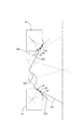
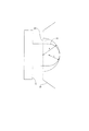
図2及び図3は、第1転動体31及び第2転動体32の接触部31C,32Cの形状についての説明図である。図2には、主軸Jに対する支持ピン21の傾斜角が異なる3つの遊星ローラ20が重複して記載されている。図3は、図2の一部を拡大して示した拡大図である。
[Shapes of
2 and 3 are explanatory views of the shapes of the
図中のa1〜a3は、第1転動体31と遊星ローラ20との接触点の一例であり、支持ピン21の傾斜角に応じて、第1転動体31の接触部31C上を移動する。また、図中のb1〜b3は、第2転動体32と遊星ローラ20との接触点の一例であり、支持ピン21の傾斜角に応じて、第2転動体32の接触部32C上を移動する。
In the drawing, a1 to a3 are examples of contact points between the first rolling
遊星ローラ20の転動面23は、球面ではなく、第1円錐面231及び第2円錐面232を含んでいる。このため、主軸Jに対する支持ピン21の傾斜角が変化すれば、主軸Jに対する転動面23の傾斜角も変化する。一方、転動面23と接触する接触部31C,32Cの形状は、支持ピン21の傾斜角を変化させたときの転動面23の包絡線と一致している。
The rolling
支持ピン21の傾斜角にかかわらず、第1転動体31及び第2転動体32の位置及び傾きは一定である。このため、接触部31C,32Cの形状を上記包絡線と一致させることにより、支持ピン21の傾斜角に応じて、転動面23との接触点を接触部31C,32C上において移動させることができる。その結果、支持ピン21の傾斜角にかかわらず、遊星ローラ20に対し、第1転動体31及び第2転動体32が良好に接触している状態を維持することができ、適切な接触圧を確保することができる。
Regardless of the inclination angle of the
第1転動体31の接触部31Cの形状について、より具体的に説明する。遊星ローラ20の第1円錐面231の主軸Jに対する傾斜角は、支持ピン21の傾斜角に応じて変化する。一方、主軸Jを含む切断面における接触部31Cの断面形状は、支持ピン21の傾斜角を変化させたときの第1円錐面231の母線の包絡線と一致する。このような構成により、支持ピン21の傾斜角に応じて、遊星ローラ20との接触点a1〜a3が接触部31C上を移動することができる。従って、支持ピン21の傾斜角にかかわらず、遊星ローラ20の第1円錐面231に対し、第1転動体31が良好に接触している状態を維持することができる。なお、第1円錐面231の母線とは、第1転動体31との接触点を含む母線であり、支持ピン21を含む平面と、第1円錐面231との交線である。
The shape of the
また、第2転動体32の接触部32Cの形状について、より具体的に説明する。遊星ローラ20の第2円錐面232の主軸Jに対する傾斜角は、支持ピン21の傾斜角に応じて変化する。一方、主軸Jを含む切断面における接触部32Cの外形は、支持ピン21の傾斜角を変化させたときの第2円錐面232の母線の包絡線と一致する。このような構成により、支持ピン21の傾斜角に応じて、遊星ローラ20との接触点b1〜b3が接触部32C上を移動することができる。従って、支持ピン21の傾斜角にかかわらず、遊星ローラ20の第2円錐面232に対し、第2転動体32が良好に接触している状態を維持することができる。なお、第2円錐面232の母線とは、第2転動体32との接触点を含む母線であり、支持ピン21を含む平面と、第2円錐面232との交線である。
The shape of the
図4の(a)〜(c)は、変速比と回転トルクについての説明図である。図中の(a)〜(c)には、低速回転時、中速回転時、高速回転時の様子がそれぞれ示されている。まず、図4を用いて、支持ピン21の傾斜角と変速比との関係について説明する。次に、図4を用いて、支持ピン21の傾斜角と回転トルクとの関係について説明する。
(A)-(c) of FIG. 4 is explanatory drawing about a gear ratio and rotational torque. (A) to (c) in the figure show states during low-speed rotation, medium-speed rotation, and high-speed rotation, respectively. First, the relationship between the inclination angle of the
[支持ピン21の傾斜と変速比の関係]
図4(b)では、支持ピン21が主軸Jと平行に配置されている。このため、第1転動体31及び第2転動体32は、回転半径が略一致する遊星ローラ20の外周上に接触する。その結果、第1転動体31及び第2転動体32の回転数は略一致し、第2転動体32は中速で回転する。
[Relationship between inclination of
In FIG. 4B, the support pins 21 are arranged in parallel with the main axis J. For this reason, the
図4(a)では、支持ピン21が主軸Jに対して傾斜し、支持ピン21の上端が下端よりも径方向外方に位置する。このため、第2転動体32は、図4(b)のときよりも回転半径がより小さな遊星ローラ20の外周上に接触し、第1転動体31は、図4(b)のときよりも回転半径がより大きな遊星ローラ20の外周上に接触する。その結果、第2転動体32の回転数は、第1転動体31よりも小さくなり、第2転動体32は低速で回転する。
In FIG. 4A, the
図4(c)では、支持ピン21が主軸Jに対し(a)の場合とは反対方向に傾斜し、支持ピン21の上端が下端よりも径方向内方に位置する。このため、第2転動体32は、図4(b)のときよりも回転半径がより大きな遊星ローラ20の外周上に接触し、第1転動体31は、図4(b)のときよりも回転半径がより小さな遊星ローラ20の外周上に接触する。その結果、第2転動体32の回転数は、第1転動体31より大きくなり、第2転動体32は、高速で回転する。
In FIG.4 (c), the
[支持ピン21の傾斜と回転トルクの関係]
第1転動体31及び第2転動体32は、軸方向において、遊星ローラ20を挟んで配置される。また、第1転動体31及び第2転動体32は、調圧カム31Aによって軸方向に付勢され、当該付勢力が法線力31F,32Fに変換され、当該法線力31F,32Fによって第1転動体31及び第2転動体32が遊星ローラ20の転動面23に押しつけられる。つまり、転動体31の法線力31Fの軸方向成分31fと、第2転動体32の法線力32Fの軸方向成分32fとは、ともに一定であり、互いに逆向きで大きさが略一致する。
[Relationship between inclination of
The
法線力31F,32Fは、遊星ローラ20の転動面23に対し、第1転動体31及び第2転動体32を押しつける力であり、第1転動体31及び第2転動体32の接触点における転動面23の法線方向に作用する。このため、法線力31F,32Fの向きは、支持ピン21の傾きに応じて変化し、法線力31F,32Fの大きさも、支持ピン21の傾きに応じて変化する。つまり、第1転動体31及び第2転動体32と、遊星ローラ20との間で伝達される回転トルクは、支持ピン21の主軸Jに対する傾きに応じて変化する。
The
より具体的には、主軸Jに対する第1円錐面231の母線の傾斜角が小さくなるほど、第1転動体31の法線力31Fは大きくなる。同様にして、主軸Jに対する第2円錐面232の母線の傾斜角が小さくなるほど、第2転動体32の法線力32Fは大きくなる。つまり、第1転動体31及び第2転動体32は、変速比に応じて回転数が小さくなるほど、遊星ローラ20との間で伝達される回転トルクが大きくなる。従って、変速比にかかわらず、常に最適な法線力31F,32Fの比が得られ、回転トルクの比が得られる。その結果、無段変速機100の伝達性能を向上させ、高効率化することができる。
More specifically, the
また、第1転動体31及び第2転動体32と、第3転動体33とは、径方向において遊星ローラ20を挟んで配置される。このため、第3転動体33は、遊星ローラ20を介して、第1転動体31の法線力31Fと、第2転動体32の法線力32Fとの合力を受け、第3転動体33の法線力33Fは、当該合力の反力となる。
Moreover, the
図4(b)では、支持ピン21が主軸Jと平行に配置されているため、第1円錐面231及び第2円錐面232の母線は、傾斜する向きが異なるが、主軸Jに対する傾斜角は略一致している。従って、第1転動体31及び第2転動体32の法線力31F,32Fの大きさも略一致する。つまり、第1転動体31及び第2転動体32は、互いの回転数が略一致すれば、遊星ローラ20に対する伝達トルクも略一致する。
In FIG. 4B, since the support pins 21 are arranged in parallel with the main axis J, the generating lines of the first
図4(a)では、第1円錐面231の母線の主軸Jに対する傾斜角が、第2円錐面232の母線の主軸Jに対する傾斜角よりも大きい。このため、第1転動体31の法線力31Fは、図4(b)のときよりも小さくなる一方、第2転動体32の法線力32Fは、図4(b)のときよりも大きくなる。つまり、図4(b)の場合と比較すれば、回転数が大きな第1転動体31は、遊星ローラ20に対する伝達トルクが小さくなり、回転数が小さな第2転動体32は、遊星ローラ20に対する伝達トルクが大きくなる。
In FIG. 4A, the inclination angle of the first
図4(c)では、第1円錐面231の母線の主軸Jに対する傾斜角が、第2円錐面232の母線の主軸Jに対する傾斜角よりも小さい。このため、第1転動体31の法線力31Fは、図4(b)のときよりも大きくなる一方、第2転動体32の法線力32Fは、図4(b)のときよりも小さくなる。つまり、図4(b)の場合と比較すれば、回転数が小さな第1転動体31は、遊星ローラ20に対する伝達トルクが大きくなり、回転数が大きな第2転動体32は、遊星ローラ20に対する伝達トルクが小さくなる。
In FIG. 4C, the inclination angle of the first
発明者らの検証結果によれば、第1円錐面231及び第2円錐面232の母線が、支持ピン21に対し略45度の角度を有している場合に、無段変速機100の効率が最も良好になることがわかった。
According to the verification results of the inventors, the efficiency of the continuously variable transmission 100 is obtained when the buses of the first
[凹部230/接触部33Cの形状]
図5は、遊星ローラ20の凹部230及び第3転動体33の接触部33Cの形状の一例を示した図であり、主軸Jを含む断面が示されている。
[Shape of
FIG. 5 is a view showing an example of the shape of the
第3転動体33の接触部33Cは円弧からなる。つまり、互いに接触する遊星ローラ20の凹部230及び第3転動体33の接触部33Cは、いずれも主軸Jを含む断面上において円弧となる。このため、接触部33C及び凹部230が損傷又は摩耗するのを抑制することができる。
The
また、接触部33Cの曲率半径Rは、凹部230の曲率半径Rと略一致するが、接触部33Cの円弧の長さは、凹部230の円弧の長さよりも長い。つまり、接触部33Cが凹部230の内面に接触している状態において、凹部230の円弧は、接触部33Cの円弧の一部と一致している。このため、接触部33Cが凹部230の内面に接触している状態を維持しつつ、軸方向の一定の範囲内において、第3転動体33をスムーズに移動させることができる。
Further, the curvature radius R of the
図6は、遊星ローラ20の凹部230及び第3転動体33の接触部33Cの形状の他の例を示した図であり、主軸Jを含む断面が示されている。
FIG. 6 is a view showing another example of the shape of the
第3転動体33の接触部33Cは円弧からなる。つまり、互いに接触する凹部230及び接触部33Cは、ともに、主軸Jを含む断面上において円弧になる。このため、接触部33C及び凹部230が、損傷又は摩耗するのを抑制することができる。
The
また、接触部33Cの曲率半径rは、凹部230の曲率半径Rよりも小さい。つまり、接触部33Cの先端が凹部230の内面の最深部に接触している状態において、接触部33Cと凹部230との間には、上下方向に隙間が形成される。このため、接触部33Cが凹部230の内面に接触している状態を維持しつつ、軸方向の一定の範囲内において、第3転動体33をスムーズに移動させることができる。また、図5の場合に比べて、第3転動体33の移動可能な距離が長くなり、主軸Jに対する支持ピン21の傾斜角の変化範囲が広くなる。このため、実現できる変速比の範囲が広くなる。
Further, the radius of curvature r of the
本実施の形態による無段変速機100は、遊星ローラ20が円環状の凹部230を有し、第3転動体33が当該凹部230の内面に接触している。このため、第3転動体33を軸方向に移動させれば、遊星ローラ20の支持ピン21を傾け、変速比を変化させることができる。このため、従来のような複雑な変速機構を有することなく、無段変速機を実現することができる。従って、無段変速機の部品点数を削減することができる。その結果、無段変速機を小型化し、あるいは、軽量化することができる。また、無段変速機の製造コストを低減して安価に提供することができる。
In the continuously variable transmission 100 according to the present embodiment, the
また、本実施の形態による無段変速機100は、遊星ローラ20の転動面23が、第1円錐面231及び第2円錐面232を有し、第1転動体31が第1円錐面231に接触し、第2転動体32が第2円錐面232に接触している。このため、第1転動体31及び第2転動体32は、変速比に応じて回転数が小さくなれば、回転トルクが大きくなる。このため、無段変速機の効率を向上させることができる。
In the continuously variable transmission 100 according to this embodiment, the rolling
また、本実施の形態による無段変速機100は、遊星ローラ20に接触する第1転動体31の接触部31Cの形状を、支持ピン21の傾きを変化させたときの第1円錐面231の母線の包絡線に一致させている。同様にして、遊星ローラ20に接触する第2転動体32の接触部32Cの形状を、支持ピン21の傾きを変化させたときの第2円錐面232の母線の包絡線に一致させている。このため、支持ピン21の傾きが変化しても、第1転動体31及び第2転動体32が遊星ローラ20の転動面23に接触している状態を維持することができる。従って、転動面23として第1円錐面231及び第2円錐面232を有する遊星ローラ20を採用することができる。
Further, the continuously variable transmission 100 according to the present embodiment has the shape of the
また、本実施の形態によれば、径方向外側から遊星ローラ20に接触する第1転動体31を入力側とし、径方向外側から遊星ローラ20に接触する第2転動体32を出力側として動作する無段変速機100を実現することができる。なお、入力側と出力側とを入れ替え可能であることは言うまでもない。
Further, according to the present embodiment, the first rolling
なお、本実施の形態では、遊星ローラ20が、第1円錐面231及び第2円錐面232を含む場合の例について説明したが、本発明は、このような構成のみに限定されない。例えば、遊星ローラ20は、環状形状の凹部230が設けられた球であってもよい。この場合、凹部230より上方の球面に第1転動体31が接触し、凹部230より下方の球面に第2転動体32が接触する。
In the present embodiment, an example in which the
実施の形態2.
実施の形態1では、遊星ローラ20が、円環状の凹部230を有する場合について説明した。これに対し、本実施の形態では、遊星ローラ20が、円環状の凸部233を有する場合について説明する。
Embodiment 2. FIG.
In Embodiment 1, the case where the
図7は、本発明の実施の形態2による無段変速機101の要部についての一構成例を示した図であり、遊星ローラ20及びその周辺に配置された構成要素のみが示されている。本実施の形態による無段変速機101は、図1の無段変速機100と比べれば、遊星ローラ20及び第3転動体33の形状が異なっている。なお、その他の構成は、図1の無段変速機100(実施の形態1)の場合と同様であるため、重複する説明を省略する。
FIG. 7 is a diagram showing a configuration example of a main part of the continuously variable transmission 101 according to the second embodiment of the present invention, and shows only the
遊星ローラ20の転動面23は、円環形状の凸部233と、凸部233よりも軸方向下方の第1円錐面231と、凸部233よりも軸方向上方の第2円錐面232とにより構成される。凸部233は、第3転動体33が接触する転動面である。凸部233は、遊星ローラ20の外周面を突出させた断面を有し、当該断面は円弧で構成される。また、凸部233は、支持ピン21の長手方向の略中央に配置され、支持ピン21を中心とする円環形状を有する。
The rolling
第3転動体33は、遊星ローラ20に対し、主軸Jの径方向内側から接触する。第3転動体33は、遊星ローラ20の凸部233が接触する接触部33Cを有する。当該接触部33Cは、径方向内方に向かって窪ませた円弧形状の断面を有する。つまり、接触部33Cの内面に遊星ローラ20の凸部233が接触する。
The
本実施の形態によれば、実施の形態1の場合と同様にして、第3転動体33を軸方向に移動させ、支持ピン21の傾きを変化させることにより、無段変速機101の変速比を変化させることができる。
According to the present embodiment, the gear ratio of the continuously variable transmission 101 is changed by moving the third rolling
実施の形態3.
実施の形態1では、モータを有しない無段変速機100について説明した。これに対し、本実施の形態では、モータを有する無段変速機102について説明する。
Embodiment 3 FIG.
In the first embodiment, the continuously variable transmission 100 having no motor has been described. In contrast, in this embodiment, a continuously variable transmission 102 having a motor will be described.
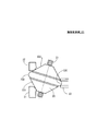
図8は、本発明の実施の形態3による無段変速機102の一構成例を示した図である。本実施の形態による無段変速機102は、図1の無段変速機100と比べれば、モータ6を有する点が異なっている。なお、その他の構成は、図1の無段変速機100(実施の形態1)の場合と同様であるため、重複する説明を省略する。 FIG. 8 is a diagram illustrating a configuration example of the continuously variable transmission 102 according to the third embodiment of the present invention. The continuously variable transmission 102 according to the present embodiment is different from the continuously variable transmission 100 of FIG. Other configurations are the same as those of the continuously variable transmission 100 (Embodiment 1) of FIG.
モータ6は、第2転動体下支持部321とスプロケット50の間に設けられ、第1転動体円筒部312を回転駆動する。モータ6は、モータ静止部及びモータ回転部により構成される。モータ静止部は、モータ支持部51を介して、ドロップアウト11に支持される。つまり、モータ静止部は、シャフト10に固定されている。一方、モータ回転部は、主軸Jを中心として回転可能に支持される。
The
モータ回転部は、ロータ62及びマグネット63を有する。ロータ62は、径方向に延びる円板形状を有し、第1転動体円筒部312に固定されている。マグネット63は、ロータ62の上面及び下面に取り付けられている。
The motor rotating unit includes a
モータ静止部は、ハウジング60及びステータ61を有する。ハウジング60は、モータ蓋部601、モータ底部602及びモータ円筒部603を有する。モータ蓋部601及びモータ底部602は、いずれも径方向に延びる円板形状を有し、軸受64を介して、第1転動体円筒部312に支持される。また、モータ蓋部601は、ロータ62よりも軸方向上方に配置され、モータ底部602は、ロータ62よりも軸方向下方に配置されている。モータ円筒部603は、円筒形状を有し、モータ蓋部601の径方向外端と、モータ底部602の径方向外端とを繋いでいる。ステータ61は、モータ蓋部601の下面及びモータ底部602の上面に取り付けられた電機子であり、マグネット63と対向する。
The motor stationary part has a
モータ6は、ステータ61に駆動電流を供給することにより、ステータ61とマグネット63との間に周方向のトルクが発生し、シャフト10に対し、第1転動体円筒部312を相対回転させることができる。
By supplying a drive current to the
本実施の形態によれば、プロスケットに付加される駆動トルクを補助するためのモータを有する無段変速機において、複雑な変速機構を採用することなく、部品点数を削減することができる。 According to the present embodiment, the continuously variable transmission having a motor for assisting the driving torque applied to the prosket can reduce the number of parts without adopting a complicated transmission mechanism.
実施の形態4.
図9は、本発明の実施の形態4による無段変速機103の一構成例を示した図であり、主軸Jを含む平面で切断したときの断面が示されている。
Embodiment 4 FIG.
FIG. 9 is a view showing a configuration example of a continuously variable transmission 103 according to the fourth embodiment of the present invention, and shows a cross section when cut along a plane including the main shaft J.
無段変速機103は、第1シャフト15、第2シャフト16、遊星ローラ20、第1転動体31、第2転動体32、第3転動体33及び歯車機構70を有している。以下、これらの各部品について詳しく説明する。なお、図1の無段変速機100と同一の構成部分については、同一の符号を付して重複する説明を省略する。
The continuously variable transmission 103 includes a
[第1シャフト15・第2シャフト16]
第1シャフト15及び第2シャフト16は、いずれも軸方向(上下方向)に延びる略円柱状の部材であり、主軸Jを中心として互いに同軸に配置されている。第1シャフト15は、第2シャフト16の下方に配置されている。また、第1シャフト15及び第2シャフト16は、第2転動体32を介して、相対回転可能に連結されている。
[
The
[遊星ローラ20]
遊星ローラ20及び支持ピン21は、図1の無段変速機100の場合と同一である。遊星ローラ支持部22は、第1シャフト15及び第2シャフト16に対し、相対回転可能に支持される。遊星ローラ支持部22は、上支持部22u、下支持部22d及び固定ピン22pにより構成される。上支持部22uは、環状形状を有し、軸受47を介して、シャフト15に支持される。下支持部22dは、上支持部22uと同軸の環状形状を有し、上支持部22uよりも軸方向下方に配置され、シャフト15が貫通する貫通孔22hを有する。固定ピン22pは、軸方向に延びる形状を有し、周方向において遊星ローラ20とは異なる位置に配置される。固定ピン22pの上端は、上支持部22uに連結され、固定ピン22pの下端は、下支持部22dに連結される。つまり、下支持部22dは、固定ピン22pを介して、上支持部22uに固定されている。上支持部22u及び下支持部22dは、周方向における遊星ローラ20に対応する位置に、ガイド部22gをそれぞれ有する。
[Planetary roller 20]
The
[第1転動体31]
第1転動体31は、無段変速機103のハウジングであり、遊星ローラ20、第2転動体32、第3転動体33及び歯車機構70を収容する。第1転動体31は、第1シャフト15及び第2シャフト16を相対回転可能に支持し、遊星ローラ20に対し、主軸Jの径方向外側から接触する。
[First rolling element 31]
The
第1転動体31は、主軸Jを中心とする環状形状を有する。より具体的には、第1転動体31は、第1転動体環状部311、第1転動体上支持部313、第1転動体下支持部314及び第1転動体円筒部315により構成される。
The
第1転動体上支持部313は、径方向に延びる略円板形状を有し、遊星ローラ20よりも軸方向上方に配置される。また、第1転動体上支持部313は、軸受45Aを介して、第2転動体円筒部325を支持する。
The first rolling element
第1転動体下支持部314は、径方向に延びる略円板形状を有し、遊星ローラ20よりも軸方向下方に配置される。また、第1転動体下支持部314は、軸受45Bを介して、第1シャフト15を支持する。
The first rolling element
第1転動体円筒部315は、円筒形状を有し、第1転動体上支持部313の径方向外端及び第1転動体下支持部314の径方向外端を繋いでいる。
The first rolling element
第1転動体環状部311は、環状形状を有し、第1転動体円筒部315の内周面に沿って軸方向上方に延びる。第1転動体環状部311の下端は、調圧カム31Aを介して、第1転動体下支持部314に支持される。第1転動体環状部311は、その上端近傍の内周面に遊星ローラ20に接触する接触部31Cを有する。当該接触部31Cは、遊星ローラ20の第1円錐面231に対し、主軸Jの径方向外側から接触する。調圧カム31Aは、主軸Jを中心とする回転トルクを利用して、軸方向の付勢力を発生する。このため、第1転動体環状部311は、遊星ローラ20の転動面23に押しつけられ、適切な接触圧が確保される。
The first rolling element
[第2転動体32]
第2転動体32は、第2シャフト16に固定され、遊星ローラ20に対し、主軸Jの径方向外側から接触する。また、第2転動体32は、主軸Jを中心とする環状形状を有する。より具体的には、第2転動体32は、第2転動体支持部324、第2転動体環状部323及び第2転動体円筒部325により構成される。
[Second rolling element 32]
The
第2転動体支持部324は、径方向に延びる略円板形状を有する。
The second rolling
第2転動体環状部323は、環状形状を有し、第2転動体支持部324の径方向外端から軸方向下方に延びる。第2転動体環状部323の上端は、調圧カム32Aを介して、第2転動体支持部324に支持される。第2転動体環状部323は、その下端近傍の内周面に遊星ローラ20に接触する接触部32Cを有する。当該接触部32Cは、遊星ローラ20の第2円錐面232に対し、主軸Jの径方向外側から接触する。調圧カム32Aは、主軸Jを中心とする回転トルクを利用して、軸方向の付勢力を発生する。このため、第2転動体環状部323は、遊星ローラ20の転動面23に押しつけられ、適切な接触圧が確保される。
The second rolling element
第2転動体円筒部325は、円筒形状を有し、第2転動体支持部324の径方向内端から軸方向上方へ延びる。第2転動体円筒部325内には、軸方向上側から第2シャフト16が圧入され、軸方向下側から第1シャフト15が嵌合される。第1シャフト15は、軸受48を介して、第2転動体支持部324に支持される。つまり、第2転動体円筒部325は、第2シャフト16に対し固定され、第1シャフト15に対し相対回転可能に支持される。
The second rolling element
[第3転動体33]
第3転動体33は、第1シャフト15に対し、軸方向に相対移動可能に支持され、遊星ローラ20に対し、主軸Jの径方向内側から接触する。また、第3転動体33は、主軸Jを中心とする環状形状を有する。より具体的には、第3転動体33は、第3転動体支持部330及び第3転動体円筒部331により構成される。
[Third rolling element 33]
The
第3転動体支持部330は、径方向に延びる略円板形状を有する。第3転動体支持部330は、その外周面上に、遊星ローラ20に接触する接触部33Cを有する。当該接触部33Cは、遊星ローラ20の凹部230の内面に対し、主軸Jの径方向内側から接触する。当該接触部33Cは、主軸Jを含む断面において、径方向外方に向かって凸となる円弧形状を有する。
The 3rd rolling
第3転動体円筒部331は、円筒形状を有し、第3転動体支持部330の径方向内端から軸方向下方に延びる。第3転動体円筒部331は、その内部に第1シャフト15が配置され、第1シャフト15に対してスプライン嵌合されている。このため、第3転動体33は、第1シャフト15に対し、相対回転することはできないが、軸方向に相対移動することができる。
The third rolling element
[歯車機構70]
歯車機構70は、軸受46を介して第3転動体円筒部331に支持される。歯車機構70は、図示しない外部の駆動源により駆動され、第3転動体33を軸方向に移動させる。例えば、歯車機構70としてラックアンドピニオンを採用すれば、駆動源の回転動作を利用して、第3転動体33を軸方向に移動させることができる。
[Gear mechanism 70]
The
[無段変速機103の動作]
次に、無段変速機103の動作について説明する。無段変速機103では、第1転動体31が固定され、第1シャフト15が入力側、第2シャフト16が出力側として用いられる。第3転動体33は、第1シャフト15とともに回転する。第3転動体33の回転トルクは、遊星ローラ20を介して、第2転動体32に伝達される。その結果、第2シャフト16が、第2転動体32とともに回転する。
[Operation of continuously variable transmission 103]
Next, the operation of the continuously variable transmission 103 will be described. In the continuously variable transmission 103, the first rolling
図1の無段変速機100の場合(実施の形態1)と同様、第1転動体31及び第2転動体32の相対的な回転数の比が、シャフト10に対する支持ピン21の傾斜角に応じて変化する。従って、支持ピン21の傾きを変化させることにより、無段変速機103の変速比を変化させることができる。
As in the case of the continuously variable transmission 100 of FIG. 1 (Embodiment 1), the ratio of the relative rotational speeds of the first rolling
本実施の形態によれば、第1転動体31が固定され、径方向内側から遊星ローラ20に接触する第3転動体33を入力側とし、径方向外側から遊星ローラ20に接触する第2転動体32を出力側とする無段変速機において、変速比にゼロを含む正逆転が可能になり、かつ、複雑な変速機構を採用することなく、部品点数を削減することができる。
According to the present embodiment, the first rolling
実施の形態5.
上記実施の形態では、遊星ローラ20に対し、第1転動体31及び第2転動体32が径方向外側から接触し、第3転動体33が径方向内側から接触する無段変速機100〜103の例について説明した。これに対し、実施の形態では、遊星ローラ20に対し、第1転動体31及び第2転動体32が径方向内側から接触し、第3転動体33が径方向外側から接触する無段変速機104について説明する。
Embodiment 5. FIG.
In the above embodiment, the continuously variable transmissions 100 to 103 in which the first rolling
図10は、本発明の実施の形態5による無段変速機104の一構成例を示した図であり、主軸Jを含む平面で切断したときの断面が示されている。 FIG. 10 is a view showing a configuration example of a continuously variable transmission 104 according to the fifth embodiment of the present invention, and shows a cross section when cut along a plane including the main shaft J.
無段変速機104は、第1シャフト15、第2シャフト16、遊星ローラ20、第1転動体31、第2転動体32、第3転動体33、調整レバー71及びハウジング8を有している。以下、これらの各部品について詳しく説明する。なお、図1の無段変速機100と同一の構成部分については、同一の符号を付して重複する説明を省略する。
The continuously variable transmission 104 includes a
[第1シャフト15/第2シャフト16]
第1シャフト15及び第2シャフト16は、いずれも軸方向(上下方向)に延びる略円柱状の部材であり、主軸Jを中心として互いに同軸に配置されている。第1シャフト15は、第2シャフト16の下方に配置されている。第1シャフト15は、軸受46Aを介して、ハウジング8に支持され、第2シャフト16は、軸受46Bを介して、ハウジング8に支持される。
[
The
[遊星ローラ支持部22]
遊星ローラ支持部22は、ハウジング8に固定されている。遊星ローラ支持部22を構成する一対のガイド部22gは、例えば、同心に配置された円弧形状を有し、支持ピン21の両端は、これらのガイド部22gに沿って移動自在に支持される。ガイド部22gは、ハウジング下支持部80の上面及びハウジング上支持部81の下面にそれぞれ固定されている。
[Planet roller support 22]
The planetary
[第1転動体31]
第1転動体31は、第1シャフト15に係合され、遊星ローラ20に対し、主軸Jの径方向内側から接触する。また、第1転動体31は、主軸Jを中心とする環状形状を有する。より具体的には、第1転動体31は、第1転動体支持部310及び第1転動体環状部311により構成される。
[First rolling element 31]
The
第1転動体支持部310は、径方向に延びる略円板形状を有し、第1シャフト15に固定される。
The first rolling
第1転動体環状部311は、環状形状を有し、第1転動体支持部310の軸方向上方に配置される。第1転動体環状部311の下端は、調圧カム31Aを介して、第1転動体支持部310に支持される。第1転動体環状部311は、その上端近傍の外周面に遊星ローラ20に接触する接触部31Cを有する。当該接触部31Cは、遊星ローラ20の第1円錐面231に対し、主軸Jの径方向内側から接触する。調圧カム31Aは、主軸Jを中心とする回転トルクを利用して、当該回転トルクに比例する軸方向の付勢力を発生する。このため、第1転動体環状部311は、遊星ローラ20の転動面23に押しつけられ、過不足のない適切な接触圧が確保される。
The first rolling element
[第2転動体32]
第2転動体32は、第2シャフト16に係合され、遊星ローラ20に対し、主軸Jの径方向内側から接触する。また、第2転動体32は、主軸Jを中心とする環状形状を有する。より具体的には、第2転動体32は、第2転動体支持部324及び第2転動体環状部323により構成される。
[Second rolling element 32]
The
第2転動体支持部324は、径方向に延びる略円板形状を有し、第2シャフト16に固定される。
The second rolling
第2転動体環状部323は、環状形状を有し、第2転動体支持部324の軸方向下方に配置される。第2転動体環状部323の上端は、調圧カム32Aを介して、第2転動体支持部324に支持される。第2転動体環状部323は、その下端近傍の外周面に遊星ローラ20に接触する接触部32Cを有する。当該接触部32Cは、遊星ローラ20の第2円錐面232に対し、主軸Jの径方向内側から接触する。調圧カム32Aは、主軸Jを中心とする回転トルクを利用して、当該回転トルクに比例する軸方向の付勢力を発生する。このため、第2転動体環状部323は、遊星ローラ20の転動面23に押しつけられ、適切な接触圧が確保される。
The second rolling element
[第3転動体33]
第3転動体33は、ハウジング8に対し、軸方向に相対移動可能に支持され、遊星ローラ20に対し、主軸Jの径方向外側から接触する。また、第3転動体33は、主軸Jを中心とする環状形状を有する。
[Third rolling element 33]
The
第3転動体33の内周面には、遊星ローラ20に接触する接触部33Cを有する。当該接触部33Cは、遊星ローラ20の凹部230の内面に対し、主軸Jの径方向外側から接触する。当該接触部33Cは、主軸Jを含む断面において、径方向内方に向かって凸となる円弧形状を有する。
A
[調整レバー71]
調整レバー71は、径方向に延びる形状を有し、第3転動体33の上下端面を挟むように構成される。このため、第3転動体33は、調整レバー71に対し、相対回転可能に支持されつつ、軸方向の位置が調整レバー71によって規制される。調整レバー71は、ハウジング円筒部82の貫通孔72を通り、径方向外端は、ハウジング8の外側に位置する。調整レバー71は、人が操作する操作子であってもよいし、駆動源により軸方向に駆動されるものであってもよい。
[Adjustment lever 71]
The
[ハウジング8]
ハウジング8は、遊星ローラ20、第1転動体31、第2転動体32及び第3転動体33を収容する。ハウジング8は、ハウジング下支持部80、ハウジング上支持部81、ハウジング円筒部82、ハウジング下円筒部83及びハウジング上円筒部84により構成される。
[Housing 8]
The housing 8 accommodates the
ハウジング下支持部80及びハウジング上支持部81は、いずれも径方向に延びる略円板形状を有する。ハウジング下支持部80は、遊星ローラ20よりも軸方向下方に配置され、ハウジング上支持部81は、遊星ローラ20よりも軸方向上方に配置される。ハウジング円筒部82は、遊星ローラ20及び第3転動体33を収容する円筒形状を有し、ハウジング下支持部80の径方向外端と、ハウジング上支持部81の径方向外端とを繋いでいる。また、ハウジング円筒部82は、調整レバー71のための貫通孔72を有する。ハウジング下円筒部83は、円筒形状を有し、ハウジング下支持部80の径方向内端から軸方向下方に延びる。ハウジング上円筒部84は、円筒形状を有し、ハウジング上支持部81の径方向内端から軸方向上方に延びる。
Both the housing
[無段変速機104の動作]
次に、無段変速機104の動作について説明する。ハウジング8が固定され、第1シャフト15が入力側、第2シャフト16が出力側として用いられる。第1転動体31は、第1シャフト15とともに回転する。第1転動体31の回転トルクは、遊星ローラ20を介して、第2転動体32に伝達される。その結果、第2シャフト16が、第2転動体32とともに回転する。
[Operation of continuously variable transmission 104]
Next, the operation of the continuously variable transmission 104 will be described. The housing 8 is fixed, and the
図1の無段変速機100の場合(実施の形態1)と同様、第1転動体31及び第2転動体32の相対的な回転数の比が、シャフト10に対する支持ピン21の傾斜角に応じて変化する。従って、調整レバー71を軸方向に移動させ、支持ピン21の傾きを変化させることにより、無段変速機103の変速比を変化させることができる。
As in the case of the continuously variable transmission 100 of FIG. 1 (Embodiment 1), the ratio of the relative rotational speeds of the first rolling
本実施の形態によれば、遊星ローラ20に対し、第1転動体31及び第2転動体32が径方向内側から接触し、第3転動体33が径方向外側から接触する無段変速機において、複雑な変速機構を採用することなく、変速比範囲を大きくすることができ、高効率化することができ、部品点数を大幅に削減することができる。
According to the present embodiment, in the continuously variable transmission in which the first rolling
100〜104 無段変速機
10 シャフト
11 ドロップアウト
12 調整ロッド
13 中空部
15 第1シャフト
16 第2シャフト
20 遊星ローラ
21 支持ピン
22 遊星ローラ支持部
22d 下支持部
22g ガイド部
22h 貫通孔
22p 固定ピン
22u 上支持部
23 転動面
230 凹部
231 第1円錐面
232 第2円錐面
233 凸部
31 第1転動体
310 第1転動体支持部
310A 小径支持部
310B 円環部
310C ボルト
311 第1転動体環状部
312、315 第1転動体円筒部
313 第1転動体上支持部
314 第1転動体下支持部
31A 調圧カム
31C 接触部
31F 法線力
31f 法線力の軸方向成分
32 第2転動体
320 第2転動体上支持部
321 第2転動体下支持部
322,325 第2転動体円筒部
323 第2転動体環状部
324 第2転動体支持部
32A 調圧カム
32C 接触部
32F 法線力
32f 法線力の軸方向成分
33 第3転動体
330 転動体支持部
331 転動体円筒部
33C 接触部
41,42A,42B,43,45,46,46A,46B,47,48 軸受
50 スプロケット
51 モータ支持部
6 モータ
64 軸受
70 歯車機構
71 調整レバー
72 貫通孔
8 ハウジング
80 ハウジング下支持部
81 ハウジング上支持部
82 ハウジング円筒部
83 ハウジング下円筒部
84 ハウジング上円筒部
a1〜a3,b1〜b3 接触点
J 主軸
100 to 104 continuously variable transmission 10 shaft 11 dropout 12 adjustment rod 13 hollow portion 15 first shaft 16 second shaft 20 planetary roller 21 support pin 22 planetary roller support portion 22d lower support portion 22g guide portion 22h through hole 22p fixing pin 22u upper support portion 23 rolling surface 230 concave portion 231 first conical surface 232 second conical surface 233 convex portion 31 first rolling element 310 first rolling element support portion 310A small diameter support portion 310B annular portion 310C bolt 311 first rolling element Annular portions 312, 315 First rolling element cylindrical portion 313 First rolling element upper support portion 314 First rolling element lower support portion 31A Pressure adjusting cam 31C Contact portion 31F Normal force 31f Axial component 32 of normal force Second rotation Moving body 320 Second rolling element upper support part 321 Second rolling element lower support part 322, 325 Second rolling element cylindrical part 323 Second rolling element ring Part 324 second rolling element support part 32A pressure adjusting cam 32C contact part 32F normal force 32f normal force axial component 33 third rolling element 330 rolling element support part 331 rolling element cylindrical part 33C contact parts 41, 42A, 42B , 43, 45, 46, 46A, 46B, 47, 48 Bearing 50 Sprocket 51 Motor support portion 6 Motor 64 Bearing 70 Gear mechanism 71 Adjustment lever 72 Through hole 8 Housing 80 Housing lower support portion 81 Housing upper support portion 82 Housing cylindrical portion 83 Housing lower cylindrical portion 84 Housing upper cylindrical portions a1 to a3, b1 to b3 Contact point J Spindle
Claims (17)
前記主軸を中心とする環状の第2転動体と、
前記主軸を中心とする環状の第3転動体と、
前記主軸の周方向に配置される複数の遊星ローラと、
前記遊星ローラを回転可能にそれぞれ支持する複数の支持ピンと、
前記主軸を含む断面上において前記支持ピンを傾斜自在に支持する遊星ローラ支持部とを有し、
前記遊星ローラは、前記支持ピンを中心とする外周上に円環形状の凹部を有し、
前記第1転動体は、前記凹部よりも軸方向下側において、径方向の一方から前記遊星ローラの転動面に接触し、前記第3転動体に対し、軸受を介して相対回転可能に支持され、
前記第2転動体は、前記凹部よりも軸方向上側において、径方向の前記一方から前記遊星ローラの転動面に接触し、前記第3転動体に対し、軸受を介して相対回転可能に支持され、
前記第3転動体は、径方向の他方から、前記遊星ローラの前記凹部に接触し、前記遊星ローラ支持部に対し、上下方向に相対移動可能に支持され、
前記第3転動体は、前記遊星ローラの前記凹部の内面に接触する円弧形状の接触部を有し、
前記凹部の内面は、前記主軸を含む断面上において円弧であり、
前記凹部の断面の曲率半径は、前記第3転動体の前記接触部の曲率半径よりも大きいことを特徴とする摩擦式無段変速機。 An annular first rolling element centered on a main axis extending in the vertical direction;
An annular second rolling element centered on the main axis;
An annular third rolling element centered on the main axis;
A plurality of planetary rollers arranged in a circumferential direction of the main shaft;
A plurality of support pins for rotatably supporting the planetary rollers,
A planetary roller support portion that tiltably supports the support pin on a cross section including the main shaft,
The planetary roller has an annular recess on the outer periphery centered on the support pin,
The first rolling element is in contact with the rolling surface of the planetary roller from one of the radial directions on the lower side in the axial direction than the recess , and is supported so as to be relatively rotatable with respect to the third rolling element via a bearing. And
The second rolling element comes into contact with the rolling surface of the planetary roller from the one side in the radial direction above the concave portion in the axial direction, and is supported so as to be relatively rotatable with respect to the third rolling element via a bearing. And
The third rolling element comes into contact with the concave portion of the planetary roller from the other in the radial direction, and is supported so as to be relatively movable in the vertical direction with respect to the planetary roller support portion .
The third rolling element has an arc-shaped contact portion that contacts an inner surface of the concave portion of the planetary roller,
The inner surface of the recess is an arc on a cross section including the main axis,
The friction type continuously variable transmission , wherein a radius of curvature of a cross section of the recess is larger than a radius of curvature of the contact portion of the third rolling element .
前記第3転動体は、前記遊星ローラに対し径方向内方から接触することを特徴とする請求項1に記載の摩擦式無段変速機。 The first rolling element and the second rolling element are in contact with the planetary roller from the radially outer side,
2. The friction type continuously variable transmission according to claim 1, wherein the third rolling element contacts the planetary roller from an inner side in a radial direction.
前記遊星ローラ支持部は、前記シャフトに固定され、
前記第1転動体及び前記第2転動体は、前記シャフトに対して相対回転可能に支持され、
前記第3転動体は、前記シャフトに対して上下方向に相対移動可能に支持されることを特徴とする請求項2に記載の摩擦式無段変速機。 A shaft disposed along the main axis;
The planetary roller support is fixed to the shaft;
The first rolling element and the second rolling element are supported so as to be rotatable relative to the shaft,
The friction type continuously variable transmission according to claim 2, wherein the third rolling element is supported so as to be relatively movable in the vertical direction with respect to the shaft.
前記第3転動体は、前記遊星ローラに対し径方向外方から接触することを特徴とする請求項1に記載の摩擦式無段変速機。 The first rolling element and the second rolling element are in contact with the planetary roller from the radially inner side,
2. The friction type continuously variable transmission according to claim 1, wherein the third rolling element contacts the planetary roller from an outer side in a radial direction.
前記第1転動体は、前記第1シャフトに固定され、
前記第2転動体は、前記第2シャフトに固定され、
前記遊星ローラ支持部は、前記第1シャフト及び前記第2シャフトに対して相対回転可能に支持されることを特徴とする請求項4に記載の摩擦式無段変速機。 A first shaft and a second shaft that are coaxially disposed along the main axis and are rotatable relative to each other;
The first rolling element is fixed to the first shaft;
The second rolling element is fixed to the second shaft;
The friction type continuously variable transmission according to claim 4, wherein the planetary roller support portion is supported so as to be rotatable relative to the first shaft and the second shaft.
径方向に延びる第1転動体支持部と、
前記第1転動体支持部の径方向外端に支持され、前記第1転動体支持部よりも軸方向上側に位置する第1転動体環状部と、
前記第1転動体支持部の径方向内端から軸方向下方へ延びる第1転動体円筒部とを有し、
前記第1転動体環状部が、前記遊星ローラに接触し、
前記第1転動体円筒部が、軸受を介して前記シャフトに支持されることを特徴とする請求項3に記載の摩擦式無段変速機。 The first rolling element is:
A first rolling element support portion extending in a radial direction;
A first rolling element annular portion that is supported at a radially outer end of the first rolling element support portion and is positioned on an axially upper side than the first rolling element support portion;
A first rolling element cylindrical portion extending axially downward from a radially inner end of the first rolling element support portion;
The first rolling element annular portion is in contact with the planetary roller;
The friction-type continuously variable transmission according to claim 3, wherein the first rolling element cylindrical portion is supported by the shaft via a bearing.
前記遊星ローラよりも軸方向下方において径方向に延びる第2転動体下支持部と、
前記遊星ローラよりも軸方向上方において径方向に延びる第2転動体上支持部と、
前記第2転動体下支持部の径方向外端及び前記第2転動体上支持部の径方向外端を繋ぐ第2転動体円筒部と、
前記第2転動体円筒部の内周面に固定される第2転動体環状部とを有し、
前記第2転動体環状部が、前記遊星ローラに接触し、
前記第2転動体上支持部が、軸受を介して前記シャフトに支持され、
前記第2転動体下支持部が、軸受を介して前記第1転動体円筒部に支持されることを特徴とする特徴とする請求項6に記載の摩擦式無段変速機。 The second rolling element is
A second rolling element lower support portion extending in a radial direction below the planetary roller in the axial direction;
A second rolling element upper support portion extending radially in the axial direction above the planetary roller;
A second rolling element cylindrical portion connecting the radially outer end of the second rolling element lower support part and the radial outer end of the second rolling element upper support part;
A second rolling element annular portion fixed to the inner peripheral surface of the second rolling element cylindrical portion;
The second rolling element annular portion is in contact with the planetary roller;
The second rolling element upper support portion is supported by the shaft via a bearing;
The friction type continuously variable transmission according to claim 6 , wherein the second rolling element lower support portion is supported by the first rolling element cylindrical portion via a bearing.
前記第3転動体は、前記ロッドに対し回転可能に支持されることを特徴とする請求項3に記載の摩擦式無段変速機。 A rod disposed within the shaft and movable relative to the shaft in a vertical direction;
The friction type continuously variable transmission according to claim 3, wherein the third rolling element is supported rotatably with respect to the rod.
前記モータ静止部は、前記シャフトに固定され、
前記モータ回転部は、前記第1転動体に固定されることを特徴とする請求項3に記載の摩擦式無段変速機。 A motor having a motor rotating part and a motor stationary part;
The motor stationary part is fixed to the shaft,
The friction type continuously variable transmission according to claim 3, wherein the motor rotating portion is fixed to the first rolling element.
前記遊星ローラ支持部は、前記第1シャフト及び前記第2シャフトに対して相対回転可能に支持され、
前記第1転動体は、前記第1シャフト及び前記第2シャフトに対して相対回転可能に支持され、
前記第2転動体は、前記第2シャフトに固定され、
前記第3転動体は、前記第1シャフトに対して上下方向に相対移動可能に支持されることを特徴とする請求項2に記載の摩擦式無段変速機。 The first shaft and the second shaft are disposed coaxially with each other along the main axis and are relatively rotatable,
The planetary roller support portion is supported to be rotatable relative to the first shaft and the second shaft,
The first rolling element is supported so as to be rotatable relative to the first shaft and the second shaft,
The second rolling element is fixed to the second shaft;
The friction type continuously variable transmission according to claim 2, wherein the third rolling element is supported so as to be movable relative to the first shaft in the vertical direction.
前記遊星ローラよりも軸方向下方において径方向に延びる第1転動体下支持部と、
前記遊星ローラよりも軸方向上方において径方向に延びる第1転動体上支持部と、
前記第1転動体下支持部の径方向外端及び前記第1転動体上支持部の径方向外端とを繋ぐ第1転動体円筒部と、
前記第1転動体円筒部の内周面に固定される第1転動体環状部とを有し、
前記第1転動体環状部が、前記遊星ローラに接触し、
前記第1転動体下支持部が、軸受を介して前記第1シャフトを支持し、
前記第1転動体上支持部が、軸受を介して前記第2シャフトを支持することを特徴とする特徴とする請求項15に記載の摩擦式無段変速機。 The first rolling element is:
A first rolling element lower support portion extending radially in the axial direction below the planetary roller;
A first rolling element upper support portion extending radially in the axial direction above the planetary roller;
A first rolling element cylindrical portion connecting the radially outer end of the first rolling element lower support portion and the radial outer end of the first rolling element upper support portion;
A first rolling element annular portion fixed to an inner peripheral surface of the first rolling element cylindrical portion;
The first rolling element annular portion is in contact with the planetary roller;
The first rolling element lower support portion supports the first shaft via a bearing;
The friction type continuously variable transmission according to claim 15 , wherein the first rolling element upper support portion supports the second shaft via a bearing.
径方向に延びる第2転動体支持部と、
前記第2転動体支持部の径方向外端に支持され、前記第2転動体支持部よりも軸方向下側に配置される第2転動体環状部と、
前記第2転動体支持部の径方向内端から軸方向上方へ延びる第2転動体円筒部とを有し、
前記第2転動体環状部が、前記遊星ローラに接触し、
前記第2転動体円筒部が、前記第2シャフトに嵌合されることを特徴とする請求項15又は16に記載の摩擦式無段変速機。
The second rolling element is
A second rolling element support portion extending in the radial direction;
A second rolling element annular portion that is supported at a radially outer end of the second rolling element support portion and is disposed on the lower side in the axial direction than the second rolling element support portion;
A second rolling element cylindrical portion extending axially upward from a radially inner end of the second rolling element support portion;
The second rolling element annular portion is in contact with the planetary roller;
The friction-type continuously variable transmission according to claim 15 or 16 , wherein the second rolling element cylindrical portion is fitted to the second shaft.
Priority Applications (7)
| Application Number | Priority Date | Filing Date | Title |
|---|---|---|---|
| JP2014200991A JP6408327B2 (en) | 2014-09-30 | 2014-09-30 | Friction type continuously variable transmission |
| EP15847419.7A EP3203114A4 (en) | 2014-09-30 | 2015-08-31 | Friction-type stepless transmission |
| PCT/JP2015/074647 WO2016052044A1 (en) | 2014-09-30 | 2015-08-31 | Friction-type stepless transmission |
| US15/515,284 US10145455B2 (en) | 2014-09-30 | 2015-08-31 | Friction-type continuously variable transmission |
| CN201510624160.8A CN105465305B (en) | 2014-09-30 | 2015-09-25 | Friction type stepless speed changer |
| CN201520755627.8U CN205350236U (en) | 2014-09-30 | 2015-09-25 | Friction formula buncher |
| TW104132120A TWI615564B (en) | 2014-09-30 | 2015-09-30 | Friction type continuously variable transmission |
Applications Claiming Priority (1)
| Application Number | Priority Date | Filing Date | Title |
|---|---|---|---|
| JP2014200991A JP6408327B2 (en) | 2014-09-30 | 2014-09-30 | Friction type continuously variable transmission |
Publications (2)
| Publication Number | Publication Date |
|---|---|
| JP2016070393A JP2016070393A (en) | 2016-05-09 |
| JP6408327B2 true JP6408327B2 (en) | 2018-10-17 |
Family
ID=55603326
Family Applications (1)
| Application Number | Title | Priority Date | Filing Date |
|---|---|---|---|
| JP2014200991A Active JP6408327B2 (en) | 2014-09-30 | 2014-09-30 | Friction type continuously variable transmission |
Country Status (6)
| Country | Link |
|---|---|
| US (1) | US10145455B2 (en) |
| EP (1) | EP3203114A4 (en) |
| JP (1) | JP6408327B2 (en) |
| CN (2) | CN105465305B (en) |
| TW (1) | TWI615564B (en) |
| WO (1) | WO2016052044A1 (en) |
Families Citing this family (7)
| Publication number | Priority date | Publication date | Assignee | Title |
|---|---|---|---|---|
| JP6408327B2 (en) * | 2014-09-30 | 2018-10-17 | 日本電産シンポ株式会社 | Friction type continuously variable transmission |
| JP6773297B2 (en) * | 2016-10-14 | 2020-10-21 | 日本電産シンポ株式会社 | Continuously variable transmission and bicycle |
| CN108068989A (en) * | 2016-11-18 | 2018-05-25 | 杨明芳 | The bicycle of stepless speed change device is installed |
| CN108068988A (en) * | 2016-11-18 | 2018-05-25 | 杨明芳 | Realize the stepless speed change device of bicycle variable speed |
| CN108068987B (en) * | 2016-11-18 | 2020-10-16 | 杨明芳 | Method for realizing stepless speed change of bicycle and stepless speed change structure |
| US11867262B2 (en) * | 2019-03-20 | 2024-01-09 | Nsk, Ltd. | Frictional roller reducer |
| CN111396522A (en) * | 2020-03-19 | 2020-07-10 | 吉安市瑞鹏飞精密科技有限公司 | Steel ring type friction transmission stepless speed changer |
Family Cites Families (21)
| Publication number | Priority date | Publication date | Assignee | Title |
|---|---|---|---|---|
| GB592320A (en) * | 1945-03-13 | 1947-09-15 | Frederick Whigham Mcconnel | Improvements in or relating to variable speed-gears |
| US2209497A (en) * | 1938-08-23 | 1940-07-30 | Guy H Hall | Variable ratio transmission |
| US2359540A (en) * | 1941-06-30 | 1944-10-03 | Falk Corp | Variable speed transmission |
| US2469653A (en) * | 1945-02-01 | 1949-05-10 | Kopp Jean | Stepless variable change-speed gear with roller bodies |
| US2860530A (en) * | 1954-10-29 | 1958-11-18 | Curtiss Wright Corp | Ball speed changers |
| US2826938A (en) * | 1956-08-23 | 1958-03-18 | Curtiss Wright Corp | Speed changer |
| US3407687A (en) * | 1967-03-27 | 1968-10-29 | Hayashi Tadashi | Variable ratio power transmission device |
| JPS57184351U (en) * | 1981-05-18 | 1982-11-22 | ||
| JPS5969565A (en) * | 1982-10-13 | 1984-04-19 | Mitsubishi Electric Corp | Stepless speed change gear |
| CN2221688Y (en) * | 1994-04-23 | 1996-03-06 | 胡奥利 | Steel ball conical pulley variable-speed device |
| USRE41892E1 (en) * | 1997-09-02 | 2010-10-26 | Fallbrook Technologies Inc. | Continuously variable transmission |
| JP2003021212A (en) * | 2001-07-05 | 2003-01-24 | Ntn Corp | Friction type continuously variable transmission |
| ATE550573T1 (en) * | 2004-10-05 | 2012-04-15 | Fallbrook Technologies Inc | CONTINUOUSLY ADJUSTABLE GEARBOX |
| JP2009041582A (en) * | 2007-08-06 | 2009-02-26 | Toyota Motor Corp | Planetary roller type power transmission device |
| US8469856B2 (en) * | 2008-08-26 | 2013-06-25 | Fallbrook Intellectual Property Company Llc | Continuously variable transmission |
| US20120025644A1 (en) * | 2009-04-21 | 2012-02-02 | Toyota Jidosha Kabushiki Kaisha | Electric motor having speed change function |
| JP2012122567A (en) * | 2010-12-09 | 2012-06-28 | Toyota Motor Corp | Continuously variable transmission |
| US20140094339A1 (en) * | 2011-06-10 | 2014-04-03 | Toyota Jidosha Kabushiki Kaisha | Continuously variable transmission |
| JP6408327B2 (en) * | 2014-09-30 | 2018-10-17 | 日本電産シンポ株式会社 | Friction type continuously variable transmission |
| JP2018118546A (en) * | 2017-01-23 | 2018-08-02 | トヨタ自動車株式会社 | vehicle |
| TWI610038B (en) * | 2017-02-07 | 2018-01-01 | Motive Power Industry Co Ltd | Stepless shifting ring seat drive mechanism |
-
2014
- 2014-09-30 JP JP2014200991A patent/JP6408327B2/en active Active
-
2015
- 2015-08-31 WO PCT/JP2015/074647 patent/WO2016052044A1/en active Application Filing
- 2015-08-31 US US15/515,284 patent/US10145455B2/en active Active
- 2015-08-31 EP EP15847419.7A patent/EP3203114A4/en not_active Withdrawn
- 2015-09-25 CN CN201510624160.8A patent/CN105465305B/en not_active Expired - Fee Related
- 2015-09-25 CN CN201520755627.8U patent/CN205350236U/en not_active Expired - Fee Related
- 2015-09-30 TW TW104132120A patent/TWI615564B/en active
Also Published As
| Publication number | Publication date |
|---|---|
| EP3203114A4 (en) | 2018-06-27 |
| EP3203114A1 (en) | 2017-08-09 |
| TW201612439A (en) | 2016-04-01 |
| JP2016070393A (en) | 2016-05-09 |
| CN205350236U (en) | 2016-06-29 |
| CN105465305A (en) | 2016-04-06 |
| US20170219069A1 (en) | 2017-08-03 |
| CN105465305B (en) | 2018-05-18 |
| US10145455B2 (en) | 2018-12-04 |
| WO2016052044A1 (en) | 2016-04-07 |
| TWI615564B (en) | 2018-02-21 |
Similar Documents
| Publication | Publication Date | Title |
|---|---|---|
| JP6408327B2 (en) | Friction type continuously variable transmission | |
| JP5131353B2 (en) | Continuously variable transmission | |
| WO2011101991A1 (en) | Power transmission device | |
| WO2013125041A1 (en) | Continuously variable transmission | |
| JP6356514B2 (en) | Decelerator | |
| JP5077834B2 (en) | Toroidal continuously variable transmission | |
| WO2018070372A1 (en) | Continuously variable transmission and bicycle | |
| JP6265061B2 (en) | Planetary roller traction drive device | |
| JP6154873B2 (en) | Linear transmission mechanism | |
| JP2005265089A (en) | Friction type transmission | |
| JP4947492B2 (en) | Toroidal continuously variable transmission | |
| JP5761445B2 (en) | Continuously variable transmission | |
| JP2017210035A (en) | Wheel, friction type drive device and omnidirectional movement device | |
| JP2020100369A (en) | Hub device, and vehicle including the hub device | |
| JP4734892B2 (en) | Toroidal continuously variable transmission | |
| JP2016080117A (en) | Toroidal type continuously variable transmission | |
| JP6364961B2 (en) | Toroidal continuously variable transmission | |
| JP6347122B2 (en) | Toroidal continuously variable transmission | |
| JP2007146873A (en) | Toroidal type continuously variable transmission | |
| JP2016205562A (en) | Continuously variable transmission | |
| JP2013190019A (en) | Continuously variable transmission | |
| JP2012127457A (en) | Continuously variable transmission | |
| JP2007071350A (en) | Continuously variable transmission | |
| JP2014077467A (en) | Continuously variable transmission | |
| JP2007309402A (en) | Toroidal type non-stage transmission |
Legal Events
| Date | Code | Title | Description |
|---|---|---|---|
| RD02 | Notification of acceptance of power of attorney |
Free format text: JAPANESE INTERMEDIATE CODE: A7422 Effective date: 20150722 |
|
| A621 | Written request for application examination |
Free format text: JAPANESE INTERMEDIATE CODE: A621 Effective date: 20170922 |
|
| A625 | Written request for application examination (by other person) |
Free format text: JAPANESE INTERMEDIATE CODE: A625 Effective date: 20170922 |
|
| A131 | Notification of reasons for refusal |
Free format text: JAPANESE INTERMEDIATE CODE: A131 Effective date: 20180522 |
|
| A521 | Request for written amendment filed |
Free format text: JAPANESE INTERMEDIATE CODE: A523 Effective date: 20180720 |
|
| TRDD | Decision of grant or rejection written | ||
| A01 | Written decision to grant a patent or to grant a registration (utility model) |
Free format text: JAPANESE INTERMEDIATE CODE: A01 Effective date: 20180911 |
|
| A61 | First payment of annual fees (during grant procedure) |
Free format text: JAPANESE INTERMEDIATE CODE: A61 Effective date: 20180920 |
|
| R150 | Certificate of patent or registration of utility model |
Ref document number: 6408327 Country of ref document: JP Free format text: JAPANESE INTERMEDIATE CODE: R150 |
|
| R250 | Receipt of annual fees |
Free format text: JAPANESE INTERMEDIATE CODE: R250 |
|
| R250 | Receipt of annual fees |
Free format text: JAPANESE INTERMEDIATE CODE: R250 |
|
| R250 | Receipt of annual fees |
Free format text: JAPANESE INTERMEDIATE CODE: R250 |
|
| R250 | Receipt of annual fees |
Free format text: JAPANESE INTERMEDIATE CODE: R250 |