JP2007146873A - Toroidal type continuously variable transmission - Google Patents

Toroidal type continuously variable transmission Download PDF

Info

Publication number
JP2007146873A
JP2007146873A JP2005338061A JP2005338061A JP2007146873A JP 2007146873 A JP2007146873 A JP 2007146873A JP 2005338061 A JP2005338061 A JP 2005338061A JP 2005338061 A JP2005338061 A JP 2005338061A JP 2007146873 A JP2007146873 A JP 2007146873A
Authority
JP
Japan
Prior art keywords
sleeve
cam
input
input shaft
continuously variable
Prior art date
Legal status (The legal status is an assumption and is not a legal conclusion. Google has not performed a legal analysis and makes no representation as to the accuracy of the status listed.)
Withdrawn
Application number
JP2005338061A
Other languages
Japanese (ja)
Inventor
Yasunori Oishi
保徳 大石
Current Assignee (The listed assignees may be inaccurate. Google has not performed a legal analysis and makes no representation or warranty as to the accuracy of the list.)
NSK Ltd
Original Assignee
NSK Ltd
Priority date (The priority date is an assumption and is not a legal conclusion. Google has not performed a legal analysis and makes no representation as to the accuracy of the date listed.)
Filing date
Publication date
Application filed by NSK Ltd filed Critical NSK Ltd
Priority to JP2005338061A priority Critical patent/JP2007146873A/en
Publication of JP2007146873A publication Critical patent/JP2007146873A/en
Withdrawn legal-status Critical Current

Links

Images

Abstract

<P>PROBLEM TO BE SOLVED: To provide a toroidal type continuously variable transmission capable of feeding lubricating oil into a fitting part of a sleeve of a thrust bearing and a loading cam and a belleville spring for pressing the loading cam without reducing strength and increasing size of the sleeve of the thrust bearing provided between the loading cam and an input shaft. <P>SOLUTION: Lubricating oil passages 102a, 102b are provided on a fitting face between a cam plate 7 and the sleeve. The oil passage 102a is formed along the peripheral direction on an inner peripheral face 7e of a cylindrical part 7b of the cam plate 7 fitted into an outer peripheral face of a cylindrical part of the sleeve, and a plurality of oil passages 102b extending in the radial direction by providing the same phase as that of a cam bottom 7a of the cam plate 7 connected with a driving shaft 22 are formed on an inner side end face 7c of the cylindrical part 7b. Consequently, since it is unnecessary to provide the oil passage by passing through the sleeve, lubricating oil can be fed into the fitting face without reducing strength and increasing size of the sleeve, and fretting in the fitting part of the sleeve and the cam plate 7 can be effectively prevented. <P>COPYRIGHT: (C)2007,JPO&INPIT

Description

本発明は、自動車や各種産業機械の変速機などに利用可能なトロイダル型無段変速機に関する。   The present invention relates to a toroidal continuously variable transmission that can be used for transmissions of automobiles and various industrial machines.

例えば自動車用変速機として用いるダブルキャビティ式トロイダル型無段変速機は、図4および図5に示すように構成されている。図4に示すように、ケーシング50の内側には入力軸(中心軸)1が回転自在に支持されており、この入力軸1の外周には、2つの入力側ディスク2,2と2つの出力側ディスク3,3とが取り付けられている。また、入力軸1の中間部の外周には出力歯車4が回転自在に支持されている。この出力歯車4の中心部に設けられた円筒状のフランジ部4a,4aには、出力側ディスク3,3がスプライン結合によって連結されている。   For example, a double-cavity toroidal continuously variable transmission used as a transmission for an automobile is configured as shown in FIGS. As shown in FIG. 4, an input shaft (center shaft) 1 is rotatably supported inside the casing 50, and two input side disks 2, 2 and two outputs are provided on the outer periphery of the input shaft 1. Side disks 3 and 3 are attached. An output gear 4 is rotatably supported on the outer periphery of the intermediate portion of the input shaft 1. Output side disks 3 and 3 are connected to cylindrical flange portions 4a and 4a provided at the center of the output gear 4 by spline coupling.

入力軸1は、図中左側に位置する入力側ディスク2とカム板7との間に設けられたローディングカム式の押圧装置12を介して、駆動軸22により回転駆動されるようになっている。また、出力歯車4は、2つの部材の結合によって構成された仕切壁13を介してケーシング50内に支持されており、これにより、入力軸1の軸線Oを中心に回転できる一方で、軸線O方向の変位が阻止されている。   The input shaft 1 is rotationally driven by a drive shaft 22 via a loading cam type pressing device 12 provided between an input side disk 2 and a cam plate 7 located on the left side in the drawing. . The output gear 4 is supported in the casing 50 via a partition wall 13 formed by coupling two members, so that the output gear 4 can rotate around the axis O of the input shaft 1 while the axis O. Directional displacement is prevented.

出力側ディスク3,3は、入力軸1との間に介在されたニードル軸受5,5によって、入力軸1の軸線Oを中心に回転自在に支持されている。また、図中左側の入力側ディスク2は、入力軸1にボールスプライン6を介して支持され、図中右側の入力側ディスク2は、入力軸1にスプライン結合されており、これら入力側ディスク2は入力軸1と共に回転するようになっている。また、入力側ディスク2,2の内側面(凹面)2a,2aと出力ディスク3,3の内側面(凹面)3a,3aとの間には、パワーローラ11(図5参照)が回転自在に挟持されている。   The output side disks 3 and 3 are supported by needle bearings 5 and 5 interposed between the input shaft 1 so as to be rotatable about the axis O of the input shaft 1. Further, the left input side disk 2 in the figure is supported on the input shaft 1 via a ball spline 6, and the right side input disk 2 in the figure is splined to the input shaft 1. Rotates with the input shaft 1. A power roller 11 (see FIG. 5) is rotatable between the inner side surfaces (concave surfaces) 2a and 2a of the input side disks 2 and 2 and the inner side surfaces (concave surfaces) 3a and 3a of the output disks 3 and 3. It is pinched.

図4中右側に位置する入力側ディスク2の内周面2cには、段差部2bが設けられ、この段差部2bに、入力軸1の外周面1aに設けられた段差部1bが突き当てられるとともに、入力側ディスク2の背面(図4の右面)がローディングナット9に突き当てられている。これによって、入力側ディスク2の入力軸1に対する軸線O方向の変位が実質的に阻止されている。また、カム板7と入力軸1の鍔部1dとの間には、皿ばね8が設けられており、この皿ばね8は、各ディスク2,2,3,3の凹面2a,2a,3a,3aとパワーローラ11,11の周面11a,11aとの当接部に押圧力を付与する。   A step 2b is provided on the inner peripheral surface 2c of the input disk 2 located on the right side in FIG. 4, and the step 1b provided on the outer peripheral surface 1a of the input shaft 1 is abutted against the step 2b. At the same time, the back surface (the right surface in FIG. 4) of the input side disk 2 is abutted against the loading nut 9. Thereby, the displacement of the input side disk 2 in the direction of the axis O with respect to the input shaft 1 is substantially prevented. Further, a disc spring 8 is provided between the cam plate 7 and the flange 1d of the input shaft 1, and this disc spring 8 is a concave surface 2a, 2a, 3a of each disk 2, 2, 3, 3. , 3a and the contact surface between the peripheral surfaces 11a and 11a of the power rollers 11 and 11 are applied with a pressing force.

図4のA−A線に沿う断面図である図5に示すように、ケーシング50の内側であって、出力側ディスク3,3の側方位置には、両ディスク3,3を両側から挟む状態で一対のヨーク23A,23Bが支持されている。これら一対のヨーク23A,23Bは、鋼等の金属のプレス加工あるいは鍛造加工により矩形状に形成されている。そして、後述するトラニオン15の両端部に設けられた枢軸14を揺動自在に支持するため、ヨーク23A,23Bの四隅には、円形の支持孔18が設けられるとともに、ヨーク23A,23Bの幅方向の中央部には、円形の係止孔19が設けられている。   As shown in FIG. 5, which is a cross-sectional view taken along the line AA in FIG. 4, both discs 3, 3 are sandwiched from both sides inside the casing 50 and at the side positions of the output side discs 3, 3. The pair of yokes 23A and 23B is supported in the state. The pair of yokes 23A and 23B are formed in a rectangular shape by pressing or forging a metal such as steel. In order to support pivots 14 provided at both ends of the trunnion 15 to be described later in a swingable manner, circular support holes 18 are provided at the four corners of the yokes 23A and 23B, and the width direction of the yokes 23A and 23B. A circular locking hole 19 is provided at the center of the.

一対のヨーク23A,23Bは、ケーシング50の内面の互いに対向する部分に形成された支持ポスト64,68により、僅かに変位できるように支持されている。これらの支持ポスト64,68はそれぞれ、入力側ディスク2の内側面2aと出力側ディスク3の内側面3aとの間にある第1のキャビティ221および第2のキャビティ222にそれぞれ対向する状態で設けられている。   The pair of yokes 23 </ b> A and 23 </ b> B are supported so as to be slightly displaceable by support posts 64 and 68 formed on portions of the inner surface of the casing 50 facing each other. These support posts 64 and 68 are provided so as to face the first cavity 221 and the second cavity 222, respectively, between the inner side surface 2a of the input side disk 2 and the inner side surface 3a of the output side disk 3. It has been.

したがって、ヨーク23A,23Bは、各支持ポスト54,68に支持された状態で、その一端部が第1のキャビティ221の外周部分に対向するとともに、その他端部が第2のキャビティ222の外周部分に対向している。   Accordingly, the yokes 23 </ b> A and 23 </ b> B are supported by the support posts 54 and 68, one end thereof faces the outer peripheral portion of the first cavity 221, and the other end is the outer peripheral portion of the second cavity 222. Opposite to.

第1および第2のキャビティ221,222は同一構造であるため、以下、第1のキャビティ221のみについて説明する。   Since the first and second cavities 221 and 222 have the same structure, only the first cavity 221 will be described below.

図5に示すように、ケーシング50の内側において、第1のキャビティ221には、入力軸1に対し捻れの位置にある一対の枢軸14,14を中心として揺動する一対のトラニオン15,15が設けられている。なお、図5においては、入力軸1の図示は省略している。各トラニオン15,15は、その本体部である支持板部16の長手方向(図5の上下方向)の両端部に、この支持板部16の内側面側に折れ曲がる状態で形成された一対の折れ曲がり壁部20,20を有している。そして、この折れ曲がり壁部20,20によって、各トラニオン15,15には、パワーローラ11を収容するための凹状のポケット部Pが形成される。また、各折れ曲がり壁部20,20の外側面には、各枢軸14,14が互いに同心的に設けられている。   As shown in FIG. 5, inside the casing 50, the first cavity 221 has a pair of trunnions 15, 15 that swing about a pair of pivots 14, 14 that are twisted with respect to the input shaft 1. Is provided. In addition, illustration of the input shaft 1 is abbreviate | omitted in FIG. Each trunnion 15, 15 is a pair of bent portions formed at both ends in the longitudinal direction (vertical direction in FIG. 5) of the support plate portion 16 that is the main body portion in a state of being bent toward the inner side surface of the support plate portion 16. Wall portions 20 and 20 are provided. The bent wall portions 20 and 20 form concave pocket portions P for accommodating the power rollers 11 in the trunnions 15 and 15. Further, the pivot shafts 14 and 14 are concentrically provided on the outer side surfaces of the bent wall portions 20 and 20, respectively.

支持板部16の中央部には円孔21が形成され、この円孔21には変位軸23の基端部(第1の軸部)23aが支持されている。そして、各枢軸14,14を中心として各トラニオン15,15を揺動させることにより、これら各トラニオン15,15の中央部に支持された変位軸23の傾斜角度を調節できるようになっている。また、各トラニオン15,15の内側面から突出する変位軸23の先端部(第2の軸部)23bの周囲には、各パワーローラ11が回転自在に支持されており、各パワーローラ11,11は、各入力側ディスク2,2および各出力側ディスク3,3の間に挟持されている。なお、各変位軸23,23の基端部23aと先端部23bとは、互いに偏心している。   A circular hole 21 is formed in the center portion of the support plate portion 16, and a base end portion (first shaft portion) 23 a of the displacement shaft 23 is supported in the circular hole 21. Then, by swinging each trunnion 15, 15 about each pivot 14, 14, the inclination angle of the displacement shaft 23 supported at the center of each trunnion 15, 15 can be adjusted. In addition, each power roller 11 is rotatably supported around the tip end portion (second shaft portion) 23b of the displacement shaft 23 protruding from the inner surface of each trunnion 15, 15. 11 is sandwiched between the input disks 2 and 2 and the output disks 3 and 3. In addition, the base end part 23a and the front-end | tip part 23b of each displacement shaft 23 and 23 are mutually eccentric.

また、前述したように、各トラニオン15,15の枢軸14,14はそれぞれ、一対のヨーク23A,23Bに対して揺動自在および軸方向(図5の上下方向)に変位自在に支持されており、各ヨーク23A,23Bにより、トラニオン15,15はその水平方向の移動を規制されている。前述したように、各ヨーク23A,23Bの四隅には円形の支持孔18が4つ設けられており、これら支持孔18にはそれぞれ、トラニオン15の両端部に設けた枢軸14がラジアルニードル軸受30を介して揺動自在に支持されている。また、前述したように、ヨーク23A,23Bの幅方向(図5の左右方向)の中央部には、円形の係止孔19が設けられており、この係止孔19の内周面は球状凹面として、支持ポスト64,68を内嵌している。すなわち、上側のヨーク23Aは、ケーシング50に固定部材52を介して支持されている球面ポスト64によって揺動自在に支持されており、下側のヨーク23Bは、球面ポスト68およびこれを支持する駆動シリンダ31の上側シリンダボディ61によって揺動自在に支持されている。   As described above, the pivot shafts 14 and 14 of the trunnions 15 and 15 are supported so as to be swingable with respect to the pair of yokes 23A and 23B and displaceable in the axial direction (vertical direction in FIG. 5). The trunnions 15 and 15 are restricted from moving in the horizontal direction by the yokes 23A and 23B. As described above, four circular support holes 18 are provided at the four corners of each of the yokes 23 </ b> A and 23 </ b> B. The pivot shafts 14 provided at both ends of the trunnion 15 are respectively provided in the support holes 18 with the radial needle bearings 30. It is supported so as to be able to swing through. Further, as described above, the circular locking hole 19 is provided in the central portion of the yokes 23A and 23B in the width direction (left-right direction in FIG. 5), and the inner peripheral surface of the locking hole 19 is spherical. Support posts 64 and 68 are internally fitted as concave surfaces. That is, the upper yoke 23A is swingably supported by the spherical post 64 supported by the casing 50 via the fixing member 52, and the lower yoke 23B is supported by the spherical post 68 and the drive for supporting the same. The upper cylinder body 61 of the cylinder 31 is swingably supported.

なお、各トラニオン15,15に設けられた各変位軸23,23は、入力軸1に対し、互いに180度反対側の位置に設けられている。また、これらの各変位軸23,23の先端部23bが基端部23aに対して偏心している方向は、両ディスク2,2,3,3の回転方向に対して同方向(図5で上下逆方向)となっている。また、偏心方向は、入力軸1の配設方向に対して略直交する方向となっている。したがって、各パワーローラ11,11は、入力軸1の長手方向に若干変位できるように支持される。その結果、押圧装置12が発生するスラスト荷重に基づく各構成部材の弾性変形等に起因して、各パワーローラ11,11が入力軸1の軸方向に変位する傾向となった場合でも、各構成部材に無理な力が加わらず、この変位が吸収される。   The displacement shafts 23 and 23 provided in the trunnions 15 and 15 are provided at positions 180 degrees opposite to the input shaft 1. Further, the direction in which the distal end portion 23b of each of the displacement shafts 23, 23 is eccentric with respect to the base end portion 23a is the same direction as the rotational direction of both the disks 2, 2, 3, 3 (in FIG. (Reverse direction). Further, the eccentric direction is a direction substantially orthogonal to the direction in which the input shaft 1 is disposed. Accordingly, the power rollers 11 and 11 are supported so that they can be slightly displaced in the longitudinal direction of the input shaft 1. As a result, even if each power roller 11, 11 tends to be displaced in the axial direction of the input shaft 1 due to elastic deformation of each component member based on the thrust load generated by the pressing device 12, each component This displacement is absorbed without applying an excessive force to the member.

また、パワーローラ11の外側面とトラニオン15の支持板部16の内側面との間には、パワーローラ11の外側面の側から順に、スラスト転がり軸受であるスラスト玉軸受24と、スラストニードル軸受25とが設けられている。このうち、スラスト玉軸受24は、各パワーローラ11に加わるスラスト方向の荷重を支承しつつ、これら各パワーローラ11の回転を許容するものである。このようなスラスト玉軸受24はそれぞれ、複数個ずつの玉26,26と、これら各玉26,26を転動自在に保持する円環状の保持器27と、円環状の外輪28とから構成されている。また、各スラスト玉軸受24の内輪軌道は各パワーローラ11の外側面(大端面)に、外輪軌道は各外輪28の内側面にそれぞれ形成されている。   Further, between the outer surface of the power roller 11 and the inner surface of the support plate portion 16 of the trunnion 15, a thrust ball bearing 24, which is a thrust rolling bearing, and a thrust needle bearing are sequentially arranged from the outer surface side of the power roller 11. 25. Among these, the thrust ball bearing 24 supports the rotation of each power roller 11 while supporting the load in the thrust direction applied to each power roller 11. Each of the thrust ball bearings 24 is composed of a plurality of balls 26, 26, an annular retainer 27 for holding the balls 26, 26 in a freely rolling manner, and an annular outer ring 28. ing. Further, the inner ring raceway of each thrust ball bearing 24 is formed on the outer side surface (large end surface) of each power roller 11, and the outer ring raceway is formed on the inner side surface of each outer ring 28.

また、スラストニードル軸受25は、トラニオン15の支持板部16の内側面と外輪28の外側面との間に挟持されている。このようなスラストニードル軸受25は、パワーローラ11から各外輪28に加わるスラスト荷重を支承しつつ、これらパワーローラ11および外輪28が各変位軸23の基端部23aを中心として揺動することを許容する。   The thrust needle bearing 25 is sandwiched between the inner surface of the support plate portion 16 of the trunnion 15 and the outer surface of the outer ring 28. Such a thrust needle bearing 25 supports the thrust load applied to each outer ring 28 from the power roller 11, while the power roller 11 and the outer ring 28 swing around the base end portion 23 a of each displacement shaft 23. Allow.

さらに、各トラニオン15,15の一端部(図5の下端部)にはそれぞれ駆動ロッド(枢軸14から延びる軸部)29,29が設けられており、各駆動ロッド29,29の中間部外周面に駆動ピストン(油圧ピストン)33,33が固設されている。そして、これら各駆動ピストン33,33はそれぞれ、上側シリンダボディ61と下側シリンダボディ62とによって構成された駆動シリンダ31内に油密に嵌装されている。これら各駆動ピストン33,33と駆動シリンダ31とで、各トラニオン15,15を、これらトラニオン15,15の枢軸14,14の軸方向に変位させる駆動装置32を構成している。   Further, drive rods (shaft portions extending from the pivot shaft) 29 and 29 are provided at one end portions (lower end portions in FIG. 5) of the trunnions 15 and 15, respectively, and outer peripheral surfaces of intermediate portions of the drive rods 29 and 29 are provided. The drive pistons (hydraulic pistons) 33, 33 are fixedly provided. Each of these drive pistons 33 and 33 is oil-tightly fitted in a drive cylinder 31 constituted by an upper cylinder body 61 and a lower cylinder body 62. The drive pistons 33 and 33 and the drive cylinder 31 constitute a drive device 32 that displaces the trunnions 15 and 15 in the axial direction of the pivots 14 and 14 of the trunnions 15 and 15.

このように構成されたトロイダル型無段変速機の場合、駆動軸22の回転は、押圧装置12を介して、各入力側ディスク2,2および入力軸1に伝えられる。そして、これら入力側ディスク2,2の回転が、一対のパワーローラ11,11を介して各出力側ディスク3,3に伝えられ、更にこれら各出力側ディスク3,3の回転が、出力歯車4より取り出される。   In the case of the toroidal continuously variable transmission configured as described above, the rotation of the drive shaft 22 is transmitted to the input side disks 2 and 2 and the input shaft 1 via the pressing device 12. Then, the rotation of the input side disks 2 and 2 is transmitted to the output side disks 3 and 3 via the pair of power rollers 11 and 11, and the rotation of the output side disks 3 and 3 is further transmitted to the output gear 4. It is taken out more.

入力軸1と出力歯車4との間の回転速度比を変える場合には、一対の駆動ピストン33,33を互いに逆方向に変位させる。これら各駆動ピストン33,33の変位に伴って、一対のトラニオン15,15が互いに逆方向に変位する。例えば、図5の左側のパワーローラ11が同図の下側に、同図の右側のパワーローラ11が同図の上側にそれぞれ変位する。その結果、これら各パワーローラ11,11の周面11a,11aと各入力側ディスク2,2および各出力側ディスク3,3の内側面2a,2a,3a,3aとの当接部に作用する接線方向の力の向きが変化する。そして、この力の向きの変化に伴って、各トラニオン15,15が、ヨーク23A,23Bに枢支された枢軸14,14を中心として、互いに逆方向に揺動する。   When changing the rotational speed ratio between the input shaft 1 and the output gear 4, the pair of drive pistons 33, 33 are displaced in opposite directions. As the drive pistons 33 and 33 are displaced, the pair of trunnions 15 and 15 are displaced in directions opposite to each other. For example, the power roller 11 on the left side in FIG. 5 is displaced to the lower side in the figure, and the power roller 11 on the right side in the figure is displaced to the upper side in the figure. As a result, the peripheral surfaces 11a and 11a of the power rollers 11 and 11 act on contact portions of the input side disks 2 and 2 and the inner side surfaces 2a, 2a, 3a and 3a of the output side disks 3 and 3, respectively. The direction of the tangential force changes. As the force changes, the trunnions 15 and 15 swing in opposite directions around the pivots 14 and 14 pivotally supported by the yokes 23A and 23B.

その結果、各パワーローラ11,11の周面11a,11aと各内側面2a,3aとの当接位置が変化し、入力軸1と出力歯車4との間の回転速度比が変化する。また、これら入力軸1と出力歯車4との間で伝達するトルクが変動し、各構成部材の弾性変形量が変化すると、各パワーローラ11,11およびこれら各パワーローラ11,11に付属の外輪28,28が、各変位軸23,23の基端部23a、23aを中心として僅かに回動する。これら各外輪28,28の外側面と各トラニオン15,15を構成する支持板部16の内側面との間には、それぞれスラストニードル軸受25,25が存在するため、前記回動は円滑に行われる。したがって、前述のように各変位軸23,23の傾斜角度を変化させるための力が小さくて済む。   As a result, the contact position between the peripheral surfaces 11a and 11a of the power rollers 11 and 11 and the inner surfaces 2a and 3a changes, and the rotational speed ratio between the input shaft 1 and the output gear 4 changes. Further, when the torque transmitted between the input shaft 1 and the output gear 4 fluctuates and the amount of elastic deformation of each component changes, the power rollers 11 and 11 and the outer rings attached to the power rollers 11 and 11 will be described. 28 and 28 slightly rotate around the base end portions 23a and 23a of the displacement shafts 23 and 23, respectively. Since the thrust needle bearings 25 and 25 exist between the outer side surfaces of the outer rings 28 and 28 and the inner side surfaces of the support plate portions 16 constituting the trunnions 15 and 15, respectively, the rotation is performed smoothly. Is called. Therefore, as described above, the force for changing the inclination angle of each displacement shaft 23, 23 can be small.

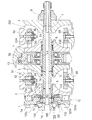
ところで、以上のようなトロイダル型無段変速機の中には、図6に示すように、入力軸1の鍔部1dとローディングカム装置12を構成するカム板7との間にスラスト荷重を支承するスラスト玉軸受166が設けられた構造のものもある(例えば、特許文献1参照)。このような構造の一例を具体的に説明すると、入力軸1の鍔部1dの片側面にアンギュラ型の内輪軌道156が形成されるとともに、この内輪軌道156と外輪であるスリーブ120の内周面に形成されたアンギュラ型の外輪軌道120eとの間に複数個の玉(転動体)165が配置されることによりアンギュラ型の玉軸受166が構成されている。スリーブ120は、円筒部120bと、この円筒部120bの左側の端部に一体形成された外向鍔部120cと、円筒部120bの右側の端部に一体形成された嵌入部120aとを備えている。そして、スリーブ120の円筒部120bの外周面がカム板7の径方向中間部に設けられた円筒部7bの内周面7eとガタつきなく軸方向に変位自在に外嵌されて、カム板7の円筒部7bの内側端面7cにスリーブ120の円筒部120bの端面が突き当てられるとともに、スリーブ120の嵌入部120aがカム板7の中心孔7dに嵌入され、また、スリーブ120の外向鍔部120cとカム板7の中間部外側面との間に皿ばね(予圧ばね)170が配置されている。   Incidentally, in the toroidal type continuously variable transmission as described above, a thrust load is supported between the flange 1d of the input shaft 1 and the cam plate 7 constituting the loading cam device 12, as shown in FIG. There is a structure in which a thrust ball bearing 166 is provided (see, for example, Patent Document 1). An example of such a structure will be described in detail. An angular inner ring raceway 156 is formed on one side surface of the flange portion 1d of the input shaft 1, and the inner peripheral face of the sleeve 120 which is the inner ring raceway 156 and the outer ring is formed. An angular ball bearing 166 is configured by disposing a plurality of balls (rolling elements) 165 between the annular outer ring raceway 120e formed on the outer ring 120e. The sleeve 120 includes a cylindrical portion 120b, an outward flange portion 120c integrally formed at the left end portion of the cylindrical portion 120b, and a fitting portion 120a integrally formed at the right end portion of the cylindrical portion 120b. . The outer peripheral surface of the cylindrical portion 120b of the sleeve 120 is externally fitted to the inner peripheral surface 7e of the cylindrical portion 7b provided at the intermediate portion in the radial direction of the cam plate 7 so as to be freely displaceable in the axial direction. The end surface of the cylindrical portion 120b of the sleeve 120 is abutted against the inner end surface 7c of the cylindrical portion 7b, the fitting portion 120a of the sleeve 120 is fitted into the center hole 7d of the cam plate 7, and the outward flange portion 120c of the sleeve 120 is also fitted. And a disc spring (preload spring) 170 is disposed between the outer surface of the cam plate 7 and the intermediate portion.

また、スリーブ120の径方向内側部分と入力側ディスク2との間には、スリーブ120側から順に、スラストニードル軸受155と皿ばね(予圧ばね)142とが軸方向に互いに直列に配置されている。皿ばね142は、図7に拡大して示すように、円錐台形状の4枚の皿ばね170a,170b,170c,170dで構成されている。そして、2枚の皿ばね170a,170b同士を互いの表面および裏面が面接触するように重ね合わせて一方の組の皿ばね群172aとし、他の2枚の皿ばね170c,170d同士も互いの表面および裏面が面接触するように重ね合わせて他方の組の皿ばね群172bとし、これら一方の組の皿ばね群172aと他方の組の皿ばね群172bとの裏面同士を対向させて入力軸1の外周に配置している。これにより、皿ばね142は、一方の組の皿ばね群172aと他方の組の皿ばね群172bとの間の径方向内側に、軸方向長さがS1の隙間を有している。この隙間S1は、皿ばね142が軸方向に弾性変形する際の余裕代となる。   In addition, a thrust needle bearing 155 and a disc spring (preload spring) 142 are arranged in series in the axial direction between the radially inner portion of the sleeve 120 and the input side disk 2 in this order from the sleeve 120 side. . As shown in FIG. 7 in an enlarged manner, the disc spring 142 includes four disc springs 170a, 170b, 170c, and 170d having a truncated cone shape. Then, the two disc springs 170a and 170b are overlapped so that the front and back surfaces of each other are in surface contact with each other to form one set of disc spring groups 172a, and the other two disc springs 170c and 170d are also mutually connected. The other pair of disc spring groups 172b are overlapped so that the front surface and the back surface are in surface contact, and the input shaft is configured such that the back surfaces of the one set of disc spring groups 172a and the other set of disc spring groups 172b face each other. 1 is arranged on the outer periphery. Accordingly, the disc spring 142 has a gap having an axial length of S1 on the radially inner side between the one set of disc spring groups 172a and the other set of disc spring groups 172b. This gap S1 becomes a margin when the disc spring 142 is elastically deformed in the axial direction.

また、図7に示すように、カム板7の円筒部7bから径方向内側に延在する内側端面7cとスリーブ120の円筒部120bの端面との間には隙間S2が形成されており、この隙間S2よりも皿ばね142の前記余裕代S1が大きく設定される(S2<S1)ことにより、無負荷時の変速による入力側ディスク2の軸方向移動によって皿ばね142が完全に押し潰されることがなく、また、入力側ディスク2の移動が妨げられることもなくなり、変速不可能な状態が発生しないで済むようになっている。更に、前記隙間S2は、負荷時に、ローディングカム装置12に予圧を付与する皿ばね170が完全に押し潰される前に、カム板7の内側端面7cとスリーブ120の円筒部120bの端面とが当接するように寸法が設定されており、これにより、皿ばね170の耐久性が確保されるようになっている。すなわち、カム板7とスリーブ120との間に設けられた隙間S2は、無負荷時の変速による入力側ディスク2の移動(各部品の寸法ばらつきや組立誤差によって生じる)を許容するとともに、負荷時にローディングカムガタ防止用の皿ばね170が完全に押し潰される前にこの隙間S2がなくなり皿ばね170の耐久性を確保するようになっている。   As shown in FIG. 7, a gap S2 is formed between the inner end surface 7c extending radially inward from the cylindrical portion 7b of the cam plate 7 and the end surface of the cylindrical portion 120b of the sleeve 120. By setting the margin S1 of the disc spring 142 to be larger than the gap S2 (S2 <S1), the disc spring 142 is completely crushed by the axial movement of the input-side disc 2 due to a shift at no load. In addition, the movement of the input-side disk 2 is not hindered, so that a state in which shifting is not possible does not occur. Further, the gap S2 is in contact with the inner end surface 7c of the cam plate 7 and the end surface of the cylindrical portion 120b of the sleeve 120 before the disc spring 170 that applies preload to the loading cam device 12 is completely crushed during loading. The dimensions are set so as to be in contact with each other, whereby the durability of the disc spring 170 is ensured. In other words, the gap S2 provided between the cam plate 7 and the sleeve 120 allows the input-side disk 2 to move (due to dimensional variations and assembly errors of each part) due to a shift at no load, and at the time of load. The gap S2 is eliminated before the disc spring 170 for preventing the loading cam rattle is completely crushed, so that the durability of the disc spring 170 is ensured.

特開2000−35099号公報JP 2000-35099 A

図6および図7に示す構造のトロイダル型無段変速機では、負荷が加わると、カム板7とスリーブ120との間の隙間S2が無くなるため、入力軸1の中心孔1gから径方向外側に延びる油路200へと供給される潤滑油が、カム板7とスリーブ120との嵌合部(インロー部)およびカム板7を押圧する皿ばね170まで供給されなくなる。また、負荷が加わってカム板7とスリーブ120との間の隙間S2が無くなると、カム板7とスリーブ120との間に相対回転が殆ど生じないが、負荷によってローディングカム装置12で推力が発生すると、カム板7が変形し、前記嵌合部がその変形を受ける。また、図6および図7の構造の場合、カム板7の中心軸の位置は前記嵌合部によって決まる。したがって、前記嵌合部の隙間は数ミクロン以内である必要がある。   In the toroidal type continuously variable transmission having the structure shown in FIGS. 6 and 7, when a load is applied, the gap S2 between the cam plate 7 and the sleeve 120 disappears, so that the center hole 1g of the input shaft 1 is radially outward. The lubricating oil supplied to the extending oil passage 200 is not supplied to the fitting portion (inlay portion) between the cam plate 7 and the sleeve 120 and the disc spring 170 that presses the cam plate 7. Further, when a load is applied and the gap S2 between the cam plate 7 and the sleeve 120 disappears, there is almost no relative rotation between the cam plate 7 and the sleeve 120, but a thrust is generated in the loading cam device 12 by the load. Then, the cam plate 7 is deformed, and the fitting portion receives the deformation. 6 and 7, the position of the central axis of the cam plate 7 is determined by the fitting portion. Accordingly, the gap between the fitting portions needs to be within a few microns.

以上のことから、前記嵌合部ではフレッチングが発生し、皿ばね170では摩耗が生じ易い。そのため、図8に示すように、スリーブ120の径方向内側から外側の嵌合面に向けて延びる油穴190を設けることが考えられる。しかしながら、このようにすると、アンギュラ軸受166の近傍に油穴190が存在することとなるため、スリーブ120の強度が低下してしまう。また、この強度低下を避けるために油穴190をアンギュラ軸受166から遠ざけると、スリーブ120を軸方向に延在させる必要があり、そのためのスペースを確保することが難しくなる。   From the above, fretting occurs in the fitting portion, and the disc spring 170 is easily worn. Therefore, as shown in FIG. 8, it is conceivable to provide an oil hole 190 extending from the radially inner side of the sleeve 120 toward the outer fitting surface. However, if it does in this way, since the oil hole 190 exists in the vicinity of the angular bearing 166, the intensity | strength of the sleeve 120 will fall. Further, if the oil hole 190 is moved away from the angular bearing 166 in order to avoid this strength reduction, it is necessary to extend the sleeve 120 in the axial direction, and it is difficult to secure a space for that purpose.

本発明は、前記事情に鑑みて為されたもので、ローディングカムと入力軸との間に設けられたスラスト軸受のスリーブの強度低下および大型化を招くことなく、前記スリーブと前記ローディングカムとの嵌合部およびローディングカムを押圧する皿ばねに潤滑油を供給できるトロイダル型無段変速機を提供することを目的とする。   The present invention has been made in view of the above circumstances, and without reducing the strength and increasing the size of the sleeve of the thrust bearing provided between the loading cam and the input shaft, the sleeve and the loading cam It is an object of the present invention to provide a toroidal continuously variable transmission that can supply lubricating oil to a disc spring that presses a fitting portion and a loading cam.

前記目的を達成するために、本発明のトロイダル型無段変速機は、回転トルクが入力される入力軸と、この入力軸に結合されて入力軸と一体で回転する入力側ディスクと、この入力側ディスクとの間に設けられたパワーローラを介して入力側ディスクの回転力を所定の変速比で受ける出力側ディスクと、前記入力側ディスクの背面に配置され且つ前記入力側ディスクを軸方向へ押圧するローディングカム式の押圧装置とを備え、前記押圧装置は、前記入力軸と共に回転するローディングカムを有して成り、前記ローディングカムと前記入力軸との間にはスラスト荷重を支承する軸受が設けられ、この軸受は、前記ローディングカムと嵌合する外輪としてのスリーブと、前記入力軸の端部によって形成される内輪軌道と前記スリーブとの間に転動自在に支持された転動体とを有しているトロイダル型無段変速機において、前記ローディングカムと前記スリーブとの間の嵌合面には、潤滑油が供給される油路が形成されていることを特徴とする。   In order to achieve the above object, a toroidal continuously variable transmission according to the present invention includes an input shaft to which rotational torque is input, an input side disk coupled to the input shaft and rotating integrally with the input shaft, and the input An output-side disk that receives the rotational force of the input-side disk at a predetermined gear ratio via a power roller provided between the input-side disk and the rear surface of the input-side disk, and the input-side disk in the axial direction A loading cam type pressing device that presses, and the pressing device includes a loading cam that rotates together with the input shaft, and a bearing that supports a thrust load is provided between the loading cam and the input shaft. The bearing is provided between a sleeve as an outer ring fitted to the loading cam and an inner ring raceway formed by an end of the input shaft and the sleeve. In a toroidal-type continuously variable transmission having a freely supported rolling element, an oil passage for supplying lubricating oil is formed on a fitting surface between the loading cam and the sleeve. It is characterized by that.

上記構成において、前記油路は、前記スリーブと嵌合する前記ローディングカムの嵌合面に形成されていても良く、あるいは、前記ローディングカムと嵌合する前記スリーブの嵌合面に形成されていても良い。   In the above configuration, the oil passage may be formed on a fitting surface of the loading cam that fits the sleeve, or formed on a fitting surface of the sleeve that fits the loading cam. Also good.

また、上記構成においては、前記ローディングカムを押圧するための皿ばねが設けられ、この皿ばねは、前記嵌合面に形成された油路を通じて潤滑油が供給されるように配設されていることが好ましい。   In the above configuration, a disc spring for pressing the loading cam is provided, and the disc spring is arranged so that lubricating oil is supplied through an oil passage formed in the fitting surface. It is preferable.

本発明のトロイダル型無段変速機においては、前記ローディングカムと前記スリーブとの間の嵌合面に潤滑油路が設けられているため、スリーブを貫いて油路を設けないで済み、そのため、スリーブの強度低下および大型化を招くことなく前記嵌合面に潤滑油を供給することが可能になる。したがって、前記スリーブと前記ローディングカムとの嵌合部でのフレッチングを有効に防止できる。また、ローディングカムを押圧する皿ばねが設けられている場合には、前記嵌合部を通じて皿ばねに潤滑油を供給する構造を成すようにすれば、皿ばねの摩耗を防止することもできる。   In the toroidal type continuously variable transmission of the present invention, since a lubricating oil path is provided on the fitting surface between the loading cam and the sleeve, it is not necessary to provide an oil path through the sleeve. Lubricating oil can be supplied to the fitting surface without reducing the strength and increasing the size of the sleeve. Therefore, fretting at the fitting portion between the sleeve and the loading cam can be effectively prevented. Further, when a disc spring for pressing the loading cam is provided, the disc spring can be prevented from being worn if a structure for supplying lubricating oil to the disc spring through the fitting portion is formed.

以下、図面を参照しながら、本発明の実施形態について説明する。なお、本発明の特徴は、ローディングカムとスラスト軸受のスリーブとの間の嵌合部に対する潤滑油の供給構造にあり、その他の構成および作用は前述した従来の構成および作用と同様であるため、以下においては、本発明の特徴部分についてのみ言及し、それ以外の部分については、図4〜図8と同一の符号を付して簡潔に説明するに留める。   Hereinafter, embodiments of the present invention will be described with reference to the drawings. The feature of the present invention lies in the structure for supplying lubricating oil to the fitting portion between the loading cam and the sleeve of the thrust bearing, and the other configuration and operation are the same as the conventional configuration and operation described above. In the following, only the characteristic part of the present invention will be referred to, and other parts will be simply described with the same reference numerals as those in FIGS.

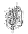
図1は本発明の実施形態を示している。本実施形態においては、前述した図6および図7の構成に加えて、図ローディングカム装置12のカム板(ローディングカム)7と、カム板7と嵌合する外輪としてのスリーブ120との間の嵌合面に、潤滑油が供給される油路が形成されている。具体的には、図1に示すように、スリーブ120と嵌合するカム板7の嵌合面に複数の油路が形成されている。さらに具体的には、スリーブ120の円筒部120bの外周面と嵌合するカム板7の円筒部7bの内周面7eに周方向に沿って油路102aが形成されるとともに、駆動軸22と結合するカム板7のカム底7aと位相を同じくして径方向に延びる複数の油路102bが円筒部7bの内側端面7cに形成されている。これらの油路102a,102bには、入力軸1の中心孔1gから径方向外側に延びる油路200を介して(更には、例えばカム板7とスリーブ120の嵌入部120aとの間に形成される隙間を介して)潤滑油が供給されるようになっている。したがって、カム板7を押圧する皿ばね170にも、これらの油路102a,102bを介して潤滑油が供給される。   FIG. 1 shows an embodiment of the present invention. In the present embodiment, in addition to the configuration of FIGS. 6 and 7 described above, the cam plate (loading cam) 7 of the loading cam device 12 and a sleeve 120 as an outer ring fitted to the cam plate 7 are provided. An oil passage to which lubricating oil is supplied is formed on the fitting surface. Specifically, as shown in FIG. 1, a plurality of oil passages are formed on the fitting surface of the cam plate 7 that fits the sleeve 120. More specifically, an oil passage 102a is formed along the circumferential direction on the inner peripheral surface 7e of the cylindrical portion 7b of the cam plate 7 fitted to the outer peripheral surface of the cylindrical portion 120b of the sleeve 120, and the drive shaft 22 A plurality of oil passages 102b extending in the radial direction in phase with the cam bottom 7a of the cam plate 7 to be coupled are formed on the inner end surface 7c of the cylindrical portion 7b. These oil passages 102 a and 102 b are formed via an oil passage 200 extending radially outward from the center hole 1 g of the input shaft 1 (further, for example, formed between the cam plate 7 and the fitting portion 120 a of the sleeve 120. Lubricating oil is supplied through a gap. Therefore, the lubricating oil is also supplied to the disc spring 170 that presses the cam plate 7 through these oil passages 102a and 102b.

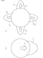
一般的なラジアル滑り軸受は、図3の(a)に示すように1方向のラジアル荷重F1を受ける(軸受の荷重分布が図中にL1で示されている)が、カム板7とスリーブ120との嵌め合い部分では、カム推力によりカム板7が変形を受けるため、図3の(b)に示すようにカムの数だけ荷重を受けることとなる(図中、F2はカム板7の変形による力(カムの数だけ荷重を受けている)、L2は嵌め合い部分の荷重分布を示している)。変形の最も大きい部分はカム板7のカム底7aの位相であるため、この部分に本実施形態のごとく油路102a,102bを設けることで、フレッチングの発生し易い部分に潤滑油を供給することができる。   A general radial plain bearing receives a radial load F1 in one direction as shown in FIG. 3A (the load distribution of the bearing is indicated by L1 in the figure), but the cam plate 7 and the sleeve 120 Since the cam plate 7 is deformed by the cam thrust at the fitting portion, a load corresponding to the number of cams is received as shown in FIG. 3B (F2 is a deformation of the cam plate 7 in the figure). (The load by the number of cams is received), L2 indicates the load distribution of the fitting portion). Since the most deformed portion is the phase of the cam bottom 7a of the cam plate 7, by providing the oil passages 102a and 102b in this portion as in this embodiment, the lubricating oil is supplied to the portion where fretting is likely to occur. Can do.

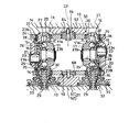
また、カム板7とスリーブ120との間の嵌合面に油路を設ける他の形態として、カム板7と嵌合するスリーブ120の嵌合面に油路を形成することも考えられる。そのような例が図2に示されている。図示のように、この例では、カム板7の円筒部7bの内周面7eと嵌合するスリーブ120の円筒部120bの外周面に沿って螺旋状に油路130aが形成されるとともに、カム板7の円筒部7bの内側端面7cと当接するスリーブ120の円筒部120bの端面に径方向に沿って油路130bが形成されている。   Further, as another mode in which an oil passage is provided on the fitting surface between the cam plate 7 and the sleeve 120, it is conceivable to form an oil passage on the fitting surface of the sleeve 120 that fits the cam plate 7. Such an example is shown in FIG. As shown in the figure, in this example, an oil passage 130a is formed in a spiral shape along the outer peripheral surface of the cylindrical portion 120b of the sleeve 120 that fits with the inner peripheral surface 7e of the cylindrical portion 7b of the cam plate 7, and the cam An oil passage 130b is formed along the radial direction on the end surface of the cylindrical portion 120b of the sleeve 120 that contacts the inner end surface 7c of the cylindrical portion 7b of the plate 7.

以上のように、本実施形態では、カム板7とスリーブ120との間の嵌合面に潤滑油路102a,102b(130a,130b)が設けられているため、スリーブ120を貫いて油路を設けないで済み、そのため、スリーブ120の強度低下および大型化を招くことなく前記嵌合面に潤滑油を供給することが可能になる。したがって、スリーブ120とカム板7との嵌合部でのフレッチングを有効に防止できる。また、カム板7を押圧する皿ばね170にも前記嵌合部(油路)を通じて潤滑油を供給することができるため、皿ばね170の摩耗を防止することもできる。また、図1および図2の構成を組み合わせれば、更に潤滑効果が向上し、高負荷容量化および長寿命化が可能となる。   As described above, in this embodiment, since the lubricating oil passages 102a and 102b (130a and 130b) are provided on the fitting surface between the cam plate 7 and the sleeve 120, the oil passage passes through the sleeve 120. Therefore, the lubricating oil can be supplied to the fitting surface without reducing the strength and increasing the size of the sleeve 120. Therefore, fretting at the fitting portion between the sleeve 120 and the cam plate 7 can be effectively prevented. Further, since the lubricating oil can be supplied to the disc spring 170 that presses the cam plate 7 through the fitting portion (oil passage), the disc spring 170 can be prevented from being worn. Further, by combining the configurations shown in FIGS. 1 and 2, the lubrication effect is further improved, and a high load capacity and a long life can be achieved.

本発明は、シングルキャビティ型やダブルキャビティ型などの様々なハーフトロイダル型無段変速機の他、トラニオンが無いフルトロイダル型無段変速機に適用することができる。   The present invention can be applied to a full toroidal continuously variable transmission without a trunnion, in addition to various half toroidal continuously variable transmissions such as a single cavity type and a double cavity type.

(a)は本発明の実施形態に係るカム板の正面図、(b)はカム板の側断面図である。(A) is a front view of the cam plate which concerns on embodiment of this invention, (b) is a sectional side view of a cam plate. (a)は本発明の他の実施形態に係るスリーブの側面図、(b)はスリーブの正面図である。(A) is a side view of the sleeve which concerns on other embodiment of this invention, (b) is a front view of a sleeve. (a)は一般的なラジアル滑り軸受の荷重分布を示す図、(b)はカム板とスリーブとの嵌め合い部分の荷重分布を示す図である。(A) is a figure which shows the load distribution of a general radial sliding bearing, (b) is a figure which shows the load distribution of the fitting part of a cam board and a sleeve. 従来から知られているトロイダル型無段変速機の具体的構造の一例を示す断面図である。It is sectional drawing which shows an example of the specific structure of the toroidal type continuously variable transmission conventionally known. 図4のA−A線に沿う断面図である。It is sectional drawing which follows the AA line of FIG. 従来の他の構造に係る図4に対応する図である。It is a figure corresponding to Drawing 4 concerning other conventional structures. 図6の要部拡大断面図である。It is a principal part expanded sectional view of FIG. 従来の更に他の構造に係る図7に対応する図である。It is a figure corresponding to Drawing 7 concerning other conventional structures.

符号の説明Explanation of symbols

1 入力軸
2 入力側ディスク
3 出力側ディスク
7 カム板(ローディングカム)
11 パワーローラ
12 ローディングカム装置(押圧装置)
102,102b 油路
120 スリーブ
130a,130b 油路
166 スラスト玉軸受
170 皿ばね
1 Input shaft 2 Input disk 3 Output disk 7 Cam plate (loading cam)
11 Power Roller 12 Loading Cam Device (Pressing Device)
102, 102b Oil passage 120 Sleeve 130a, 130b Oil passage 166 Thrust ball bearing 170 Belleville spring

Claims (4)

回転トルクが入力される入力軸と、この入力軸に結合されて入力軸と一体で回転する入力側ディスクと、この入力側ディスクとの間に設けられたパワーローラを介して入力側ディスクの回転力を所定の変速比で受ける出力側ディスクと、前記入力側ディスクの背面に配置され且つ前記入力側ディスクを軸方向へ押圧するローディングカム式の押圧装置とを備え、前記押圧装置は、前記入力軸と共に回転するローディングカムを有して成り、前記ローディングカムと前記入力軸との間にはスラスト荷重を支承する軸受が設けられ、この軸受は、前記ローディングカムと嵌合する外輪としてのスリーブと、前記入力軸の端部によって形成される内輪軌道と前記スリーブとの間に転動自在に支持された転動体とを有しているトロイダル型無段変速機において、
前記ローディングカムと前記スリーブとの間の嵌合面には、潤滑油が供給される油路が形成されていることを特徴とするトロイダル型無段変速機。
Rotation of the input disk via an input shaft to which rotational torque is input, an input disk coupled to the input shaft and rotating integrally with the input shaft, and a power roller provided between the input disk An output side disk that receives a force at a predetermined gear ratio; and a loading cam type pressing device that is disposed on the back surface of the input side disk and presses the input side disk in the axial direction. A bearing cam that rotates with the shaft, and a bearing for supporting a thrust load is provided between the loading cam and the input shaft; the bearing is a sleeve as an outer ring that fits the loading cam; A toroidal-type continuously variable transmission having an inner ring raceway formed by an end of the input shaft and a rolling element supported between the sleeve and the sleeve. Oite,
A toroidal continuously variable transmission characterized in that an oil passage to which lubricating oil is supplied is formed on a fitting surface between the loading cam and the sleeve.
前記油路は、前記スリーブと嵌合する前記ローディングカムの嵌合面に形成されていることを特徴とする請求項1に記載のトロイダル型無段変速機。   The toroidal continuously variable transmission according to claim 1, wherein the oil passage is formed on a fitting surface of the loading cam that fits the sleeve. 前記油路は、前記ローディングカムと嵌合する前記スリーブの嵌合面に形成されていることを特徴とする請求項1または請求項2に記載のトロイダル型無段変速機。   The toroidal continuously variable transmission according to claim 1, wherein the oil passage is formed on a fitting surface of the sleeve that is fitted with the loading cam. 前記ローディングカムを押圧するための皿ばねを更に備え、この皿ばねは、前記嵌合面に形成された油路を通じて潤滑油が供給されるように配設されていることを特徴とする請求項1ないし請求項3のいずれか1項に記載のトロイダル型無段変速機。   The disc spring according to claim 1, further comprising a disc spring for pressing the loading cam, wherein the disc spring is arranged so that lubricating oil is supplied through an oil passage formed in the fitting surface. The toroidal continuously variable transmission according to any one of claims 1 to 3.
JP2005338061A 2005-11-24 2005-11-24 Toroidal type continuously variable transmission Withdrawn JP2007146873A (en)

Priority Applications (1)

Application Number Priority Date Filing Date Title
JP2005338061A JP2007146873A (en) 2005-11-24 2005-11-24 Toroidal type continuously variable transmission

Applications Claiming Priority (1)

Application Number Priority Date Filing Date Title
JP2005338061A JP2007146873A (en) 2005-11-24 2005-11-24 Toroidal type continuously variable transmission

Publications (1)

Publication Number Publication Date
JP2007146873A true JP2007146873A (en) 2007-06-14

Family

ID=38208524

Family Applications (1)

Application Number Title Priority Date Filing Date
JP2005338061A Withdrawn JP2007146873A (en) 2005-11-24 2005-11-24 Toroidal type continuously variable transmission

Country Status (1)

Country Link
JP (1) JP2007146873A (en)

Cited By (1)

* Cited by examiner, † Cited by third party
Publication number Priority date Publication date Assignee Title
JP2017003042A (en) * 2015-06-12 2017-01-05 日本精工株式会社 Toroidal type continuously variable transmission

Cited By (1)

* Cited by examiner, † Cited by third party
Publication number Priority date Publication date Assignee Title
JP2017003042A (en) * 2015-06-12 2017-01-05 日本精工株式会社 Toroidal type continuously variable transmission

Similar Documents

Publication Publication Date Title
WO2012111562A1 (en) Toroidal type continuously variable transmission
JP2007162897A (en) Toroidal type continuously variable transmission
JP5007600B2 (en) Toroidal continuously variable transmission
JP4758809B2 (en) Toroidal continuously variable transmission
JP4706920B2 (en) Toroidal continuously variable transmission
JP4923989B2 (en) Toroidal continuously variable transmission
JP2008032084A (en) Toroidal continuously variable transmission
JP2007146873A (en) Toroidal type continuously variable transmission
JP4968082B2 (en) Toroidal continuously variable transmission
JP4947492B2 (en) Toroidal continuously variable transmission
JP4587119B2 (en) Toroidal continuously variable transmission
JP4972931B2 (en) Toroidal continuously variable transmission
JP4894178B2 (en) Toroidal continuously variable transmission
JP4587120B2 (en) Toroidal continuously variable transmission
JP4626883B2 (en) Toroidal continuously variable transmission
JP2007240004A (en) Power roller unit for toroidal continuously variable transmission
JP6183163B2 (en) Toroidal continuously variable transmission
JP4706959B2 (en) Toroidal continuously variable transmission
JP6390187B2 (en) Toroidal continuously variable transmission
JP6364961B2 (en) Toroidal continuously variable transmission
JP5115712B2 (en) Toroidal continuously variable transmission
JP5003140B2 (en) Toroidal continuously variable transmission
JP4513008B2 (en) Continuously variable transmission
JP2007170591A (en) Toroidal continuously variable transmission
JP2007292154A (en) Toroidal continuously variable transmission

Legal Events

Date Code Title Description
A300 Withdrawal of application because of no request for examination

Free format text: JAPANESE INTERMEDIATE CODE: A300

Effective date: 20090203