JP6401034B2 - Hollow motor - Google Patents
Hollow motor Download PDFInfo
- Publication number
- JP6401034B2 JP6401034B2 JP2014244398A JP2014244398A JP6401034B2 JP 6401034 B2 JP6401034 B2 JP 6401034B2 JP 2014244398 A JP2014244398 A JP 2014244398A JP 2014244398 A JP2014244398 A JP 2014244398A JP 6401034 B2 JP6401034 B2 JP 6401034B2
- Authority
- JP
- Japan
- Prior art keywords
- cover
- motor
- hollow shaft
- lock
- encoder
- Prior art date
- Legal status (The legal status is an assumption and is not a legal conclusion. Google has not performed a legal analysis and makes no representation as to the accuracy of the status listed.)
- Active
Links
Images


Landscapes
- Motor Or Generator Frames (AREA)
Description
本発明は、中空モータに関するものである。 The present invention relates to a hollow motor.
例えば、産業用機械の駆動源として用いられるモータの場合、モータシャフトの回転角度検出を高精度に行う必要があり、高精度の回転角度検出手段として光学式のエンコーダが用いられることが多い。また、モータシャフトを中空シャフトとして構成し、中空シャフトの内部にケーブルやチューブ等を通せるようにすることで、ケーブルやチューブ等の配索スペースを省スペース化したモータが用いられることも多い(例えば、特許文献1及び特許文献2参照)。 For example, in the case of a motor used as a drive source for an industrial machine, it is necessary to detect the rotation angle of the motor shaft with high accuracy, and an optical encoder is often used as high-precision rotation angle detection means. In addition, a motor that saves space for cables and tubes by using a motor shaft as a hollow shaft and allowing cables and tubes to pass through the hollow shaft is often used ( For example, see Patent Literature 1 and Patent Literature 2).
この種のモータでは、通常、モータの反負荷側(モータシャフトから回転出力を取り出す負荷側に対しその反対側)にエンコーダが配置され、そのエンコーダを覆うように環状カップ型のエンコーダカバーが取り付けられている。また、エンコーダカバーの内部(エンコーダを収容したカバー内部空間)に外部から塵埃などの異物が侵入しないようにする対策が必要であり、特許文献1及び特許文献2に、その対策が講じられたエンコーダ付きモータが開示されている。
In this type of motor, an encoder is usually arranged on the opposite side of the motor (on the opposite side to the load side where the rotational output is extracted from the motor shaft), and an annular cup-type encoder cover is attached to cover the encoder. ing. In addition, it is necessary to take measures to prevent foreign matters such as dust from entering the inside of the encoder cover (the cover internal space in which the encoder is housed) from the outside. Patent Document 1 and
図10は、特許文献1に記載されたエンコーダ付きモータの断面図である。
図10に示すように、このエンコーダ付きモータ501は、モータ本体部502と、モータ本体部502の反負荷側(図10中の右側)に配置されたエンコーダ部503と、からなる。
FIG. 10 is a cross-sectional view of an encoder-equipped motor described in Patent Document 1.
As shown in FIG. 10, the encoder-equipped
モータ本体部502は、ステータ534を内装した中空環状のモータケーシング530に、外周にロータマグネット518を装着した中空シャフト510を回転自在に貫通させたブラシレスモータとして構成されている。
The motor
モータケーシング530は、円筒状の中央部ハウジング531と、その中央部ハウジング531の軸方向両端開口を塞ぐように連結された負荷側と反負荷側の一対の環状の側部ハウジング532、533とからなる。モータケーシング530を貫通する中空シャフト510は、負荷側と反負荷側の側部ハウジング532、533の中央開口部(貫通孔)の内周に嵌合された2つの軸受541、542により回転自在に支持されている。
The
ステータ534は、円筒状の中央部ハウジング531の内周に嵌合されたステータコア535と、ステータコア535の各ティースにインシュレータ536を介して巻回されたコイル537とからなる。リングマグネットであるロータマグネット518は、中空シャフト510の外周上の各ティースに対応する位置に保持されている。
The
このように構成されたモータ本体部502の反負荷側の側部に、エンコーダ部503の主要素であるエンコーダ600が配置されている。エンコーダ600は、中空シャフト510の反負荷側の端部外周にハブ部611が嵌合されたエンコーダディスク部材610と、エンコーダディスク部材610のディスク本体部613のコード形成面614に対し空隙を介して対向配置されたコード読み取り用の光学素子602及びその支持部材(例えば基板)601とからなる。
An
モータ本体部502の反負荷側には、環状カップ型のエンコーダカバー(モータカバー)570が装着されており、そのカバー内部空間580にエンコーダ600が収容されている。また、エンコーダカバー570の径方向中央部には、中空シャフト510の内部に非接触で挿入されるカバーパイプ520が一体に形成されている。カバーパイプ520は、反負荷側から負荷側まで延びており、このカバーパイプ620の内部にケーブル等を挿通させることにより、ケーブル等が、回転する中空シャフト510に干渉しないようにすることができる。
An annular cup-type encoder cover (motor cover) 570 is mounted on the non-load side of the
また、カバーパイプ520が、中空シャフト510の内部に反負荷側から負荷側に向かって挿入されていることにより、カバーパイプ520の外周と中空シャフト510の内周との間に、軸方向に沿った長い環状の隙間210が確保されている。これにより、カバー内部空間580に外部から塵埃を伴う空気の流れが侵入するには、前記の長い隙間210を通らなくてはならなくなる。そのため、カバーパイプ520があることによって、外部からカバー内部空間580への塵埃等の侵入を防ぐことができる。その結果、ディスク本体部613に塵埃等が付着して、エンコーダ600の検出精度が落ちたり、それにより、モータが誤作動したりするのを防ぐことができる。
Further, since the
図11は、特許文献2に記載されたエンコーダ付きモータの要部断面図である。
図11に示すように、このエンコーダ付きモータ701では、図示しないモータ本体部の反負荷側の側方にエンコーダ部703が配置されている。エンコーダ部703には、エンコーダ800を覆うようにエンコーダカバー(モータカバー)770が配置されている。エンコーダ800は、中空シャフト710側に固定されたエンコーダディスク810と、モータケーシング及びエンコーダカバー770側に固定された光学素子802及びその支持部801とから構成されている。
FIG. 11 is a cross-sectional view of a main part of the motor with an encoder described in
As shown in FIG. 11, in this
エンコーダディスク810は、ハブ711を介して、モータ本体部及びエンコーダ部703を貫通する中空シャフト710の反負荷側の端部外周に固定されている。エンコーダディスク810にはコード形成部が設けられており、そのコード形成部に対応して、光学的にコードを読み取る光学素子802及びその支持部801が設けられている。
The
エンコーダ800はエンコーダカバー770のカバー内部空間780に収容されており、エンコーダカバー770の側壁部の径方向中央には、内周が非接触で、中空シャフト710の反負荷側の端部外周に微小隙間を介して対向するシャフト貫通孔774が設けられている。そして、このシャフト貫通孔774の内周と中空シャフト710の端部の外周との隙間からカバー内部空間780に塵埃等が侵入するのを防止する対策として、ハブ711の反負荷側の端面と、エンコーダカバー770のシャフト貫通孔774の周縁部とを微小隙間を介して軸方向に対向させ、且つ、その対向面に、互いに非接触で嵌まり合う凹部776と凸部750とを形成して、両者の対向面間にラビリンスを確保している。
The
ところで、図10に示したエンコーダ付きモータ501では、エンコーダカバー570に、中空シャフト510の内部に挿入されるカバーパイプ520を一体に設けている。従って、エンコーダカバー570のカバー内部空間580に外部の空気が侵入する経路は、中空シャフト510とカバーパイプ520との間の長く狭い隙間となり、侵入経路が長くなる分だけ、カバー内部空間580への塵埃等の侵入防止効果を高めることができる。しかし、中空シャフト510とカバーパイプ520との間の隙間を狭くするには限度があり、その隙間を通って塵埃等が侵入するおそれが依然としてあった。また、エンコーダカバー570にカバーパイプ520が一体に付いていると、組立時の取り扱いがしづらいという問題もあった。
By the way, in the
一方、図11に示したエンコーダ付きモータ701では、ハブ711の端面とエンコーダカバー770のシャフト貫通孔774の周縁部とを微小隙間を介して軸方向に対向させ、且つ、その対向面に、互いに非接触で嵌合する凹部776と凸部750を形成して、両者の対向面間にラビリンスを確保している。しかし、凹部776と凸部750を対向面に形成してラビリンスを確保するだけでは、外部からカバー内部空間780への塵埃等の侵入を充分に防ぐことはできない可能性がある。また、ハブ711やエンコーダカバー770に凹部776と凸部750を微細加工する面倒もある。
On the other hand, in the
本発明は、上述した事情に鑑みてなされたものであって、加工上の面倒や組立時の取り扱い難さを解消しつつ、モータカバー内部への塵埃等の侵入をより確実に防ぐことのできる中空モータを提供することを目的とする。 The present invention has been made in view of the above-described circumstances, and can more reliably prevent entry of dust and the like into the motor cover while eliminating troublesome processing and difficulty in handling during assembly. An object is to provide a hollow motor.
上記課題を解決するために、本発明に係る中空モータは、ステータを内装した中空環状のモータケーシングに、外周にロータマグネットを装着した中空シャフトを回転自在に貫通させ、前記モータケーシングの両端から突出した前記中空シャフトの軸方向両端のうち一端側を負荷側とすると共に他端側を反負荷側とし、前記ステータのコイルに通電することで、前記中空シャフトを前記モータケーシングに対して回転させるモータ本体部と、前記モータケーシングの前記反負荷側の端部に配置され、径方向中央の開口の周縁を前記中空シャフトの前記反負荷側の端部に微小隙間を持って対向させ、その状態で前記モータケーシングに固定されることで、前記モータケーシングの前記反負荷側の端部を外部から覆う環状のモータカバーと、前記モータカバーに、前記中空シャフトの前記反負荷側の端部を包囲するように気密に連結され、前記中空シャフトの内部に非接触で挿通されることで、前記負荷側においては、前記中空シャフトの内周と前記カバーパイプの外周との間に環状のスペースが形成されて、前記中空シャフトの露出を制限するカバーパイプと、を備え、互いに相対回転する前記モータカバー及びカバーパイプと前記中空シャフトの前記反負荷側の端部との間に、前記中空シャフトの前記内周と前記カバーパイプの前記外周との間の隙間を通って前記負荷側から前記反負荷側に流入し、その上で前記モータカバーのカバー内部空間へ侵入しようとする空気の流通を抑制する屈曲形状を有すると共に前記中空シャフトの前記内周と前記カバーパイプの前記外周との間の前記隙間より狭く形成され、前記モータケーシングの外部と連通する狭流路を確保したことを特徴とする。 In order to solve the above-mentioned problems, a hollow motor according to the present invention has a hollow annular motor casing having a stator embedded therein, and a hollow shaft having a rotor magnet mounted on the outer periphery thereof, which freely rotates, and projects from both ends of the motor casing. A motor that rotates the hollow shaft relative to the motor casing by energizing the coil of the stator with one end side as a load side and the other end side as an anti-load side among both axial ends of the hollow shaft. The main body is disposed at the end of the motor casing on the anti-load side, and the peripheral edge of the opening in the center in the radial direction is opposed to the end of the hollow shaft on the anti-load side with a minute gap. By fixing to the motor casing, an annular motor cover that covers the end of the motor casing on the side opposite to the load from the outside, To Takaba, said hollow shaft being connected in an airtight so as to surround the end of the anti-load side, the by being inserted in a non-contact manner within the hollow shaft, in the load side, of the hollow shaft An annular space is formed between the periphery and the outer periphery of the cover pipe, and the cover pipe restricts the exposure of the hollow shaft, and the motor cover and the cover pipe that rotate relative to each other and the hollow shaft between the end of the anti-load side, the through the inner circumference of the hollow shaft and the gap between the outer periphery of the cover pipe flows into the non-load side from the load side, the motor on its before between the outer periphery of the inner peripheral and the cover pipe of the hollow shaft and having a suppressing bent shape the flow of air to be intruding into the space inside the cover of the cover It is narrower than the gap, characterized in that securing a narrow channel which communicates with the outside of the motor casing.
このように構成することで、モータカバーのカバー内部空間への塵埃等の侵入をより確実に防ぐことができる。このため、カバー内部空間に塵埃等が侵入してモータ動作に不具合が生じることを防ぐことができる。さらに、例えば、カバー内部空間にエンコーダ等を配置した場合であっても、エンコーダに塵埃等が付着して検出精度が落ちたり、その結果、モータの誤動作が起きたりするのを防ぐことができる。
また、モータカバー及びカバーパイプと中空シャフトの反負荷側の端部との間に、塵埃等の流入を阻止する屈曲形状の狭流路を確保しているので、中空シャフトの内周とカバーパイプの外周との間の隙間を全長に渡って極力狭くする必要がなくなる。このため、特に負荷側において中空シャフトの内周とカバーパイプの外周との間の隙間を、余裕を持って設定することができる。よって、寸法管理が容易になると共に、片持ち支持するカバーパイプの長さを長くしたりすることも容易になる。
また、互いに相対回転するモータカバー及びカバーパイプと中空シャフトの反負荷側の端部との間に狭流路を確保するので、特に部品同士の対向面に凹部や凸部を設ける面倒を要することなく、部品の外形形状の単純な組み合わせで狭流路を構成することができる。従って、凹部や凸部を形成するような面倒な微細加工が不要となり、加工コストの低減を図ることができると共に、組立時の取り扱い難さを解消できる。
By comprising in this way, the penetration | invasion of the dust etc. to the cover internal space of a motor cover can be prevented more reliably. For this reason, it can prevent that dust etc. penetrate | invade into a cover internal space, and a malfunction arises in motor operation. Furthermore, for example, even when an encoder or the like is disposed in the cover internal space, it is possible to prevent dust from adhering to the encoder to reduce detection accuracy and, as a result, malfunction of the motor.
In addition, since a narrow narrow flow path that prevents inflow of dust and the like is secured between the motor cover and the cover pipe and the end on the opposite side of the hollow shaft, the inner periphery of the hollow shaft and the cover pipe It is no longer necessary to narrow the gap between the outer circumference of the rim as much as possible over the entire length. For this reason, especially on the load side, the gap between the inner periphery of the hollow shaft and the outer periphery of the cover pipe can be set with a margin. Therefore, it becomes easy to manage the dimensions, and it is easy to increase the length of the cover pipe that is cantilevered.
In addition, since a narrow flow path is secured between the motor cover and cover pipe that rotate relative to each other and the end portion on the opposite side of the hollow shaft, it is particularly troublesome to provide recesses and protrusions on the facing surfaces of the components. The narrow flow path can be configured with a simple combination of the external shapes of the components. Therefore, troublesome fine processing such as forming concave portions and convex portions is not required, and processing costs can be reduced, and handling difficulties during assembly can be eliminated.
本発明に係る中空モータでは、前記モータカバーは、前記径方向中央の開口の周縁壁として、前記負荷側に向けて延在し且つ内周面が前記中空シャフトの前記反負荷側の端部の外周面に隙間を持って対向する円筒状の袖筒部を有し、前記カバーパイプは、前記モータカバーに連結する際に、前記モータカバーの前記袖筒部の内周面に外周面が嵌合するボス部と、該ボス部から径方向外方へ延出し前記モータカバーの外側面に当接した状態で該モータカバーの外側面に結合されるフランジ部と、前記ボス部から軸方向に沿って前記負荷側に向けて延在し前記中空シャフトの内部に非接触で挿通される直線パイプ部と、を有し、前記狭流路は、前記中空シャフトの前記反負荷側の端面と、該端面に対して軸方向に対向する前記カバーパイプの前記ボス部の端面との間に確保された径方向に沿う第1の狭流路と、該第1の狭流路に連続し且つ前記モータカバーの前記袖筒部の内周面と前記中空シャフトの前記反負荷側の端部の外周面との間に確保された軸方向に沿う第2の狭流路と、を備えており、前記中空シャフトと前記カバーパイプの直線パイプ部との間の隙間から前記第1の狭流路にかけて直角に流路が屈曲し、前記第1の狭流路から第2の狭流路にかけて流路が屈曲していることを特徴とする。 In the hollow motor according to the present invention, the motor cover extends toward the load side as a peripheral wall of the opening in the center in the radial direction, and an inner peripheral surface of the end portion on the opposite side of the hollow shaft. The outer peripheral surface has a cylindrical sleeve tube portion facing each other with a gap, and when the cover pipe is connected to the motor cover, the outer peripheral surface is fitted to the inner peripheral surface of the sleeve tube portion of the motor cover. A boss portion, a flange portion extending radially outward from the boss portion and coupled to the outer surface of the motor cover in contact with the outer surface of the motor cover; and an axial direction from the boss portion A straight pipe portion extending toward the load side and inserted in a non-contact manner inside the hollow shaft, and the narrow flow path includes an end surface on the anti-load side of the hollow shaft, and the end surface The cover pipe facing in the axial direction with respect to the A first narrow passage along the radial direction secured between the end surface of the sleeve portion, an inner peripheral surface of the sleeve cylinder portion of the motor cover, which is continuous with the first narrow passage, and the hollow shaft. A second narrow flow path along the axial direction secured between the outer peripheral surface of the end portion on the opposite load side, and a gap between the hollow shaft and the straight pipe portion of the cover pipe The flow path is bent at right angles from the first narrow flow path to the first narrow flow path, and the flow path is bent from the first narrow flow path to the second narrow flow path.
このように構成することで、単純な構造でモータカバーの内部に塵埃等がより侵入しにくくなる。 With this configuration, dust and the like are less likely to enter the motor cover with a simple structure.
本発明に係る中空モータでは、前記モータケーシングの前記反負荷側の外部に配置され、前記モータケーシングに対する前記中空シャフトの回転角度を検出するエンコーダを備え、前記モータカバーは、前記モータケーシングの前記反負荷側の端部及び前記エンコーダを外部から覆うように形成されており、前記エンコーダは、前記中空シャフトの前記反負荷側の端部の外周に該中空シャフトと一体回転するように嵌合されたハブ部を有するエンコーダディスク部材を備え、前記エンコーダディスク部材のハブ部に形成された凹部に、前記モータカバーの前記袖筒部の先端が挿入されることで、前記袖筒部の外面と前記凹部の内面との間に、前記狭流路の一部として、前記第2の狭流路に連続する第3の狭流路が確保されていることを特徴とする。 In the hollow motor according to the present invention, the hollow motor includes an encoder that is disposed outside the anti-load side of the motor casing and detects a rotation angle of the hollow shaft with respect to the motor casing. The load side end and the encoder are formed so as to cover from the outside, and the encoder is fitted to the outer periphery of the end portion on the opposite side of the hollow shaft so as to rotate integrally with the hollow shaft. An encoder disk member having a hub portion is provided, and an outer surface of the sleeve cylinder portion and an inner surface of the recess are inserted into a recess formed in the hub portion of the encoder disk member by inserting a tip of the sleeve cylinder portion of the motor cover. And a third narrow channel continuous to the second narrow channel is secured as a part of the narrow channel. That.
このように構成することで、狭流路がさらに複雑に屈曲されることになり、モータカバーの内部に塵埃等がより一層侵入しにくくなる。 With this configuration, the narrow flow path is bent in a more complicated manner, and dust or the like is less likely to enter the inside of the motor cover.
本発明に係る中空モータでは、前記カバーパイプのフランジ部と、該フランジ部が結合される前記モータカバーの外側面との間に、前記ボス部の外周を前記袖筒部の内周に嵌合させながら、前記フランジ部を所定の回転位置で前記モータカバーの外側面に当接させ、その状態で、前記フランジ部を所定方向に回転させることで、前記カバーパイプを前記モータカバーに対して軸方向に抜け止めロックし且つ周方向に回転止めロックする回転スライド式ロック機構が設けられ、これにより、前記モータカバーに対して前記カバーパイプを着脱自在としたことを特徴とする。 In the hollow motor according to the present invention, the outer periphery of the boss portion is fitted to the inner periphery of the sleeve tube portion between the flange portion of the cover pipe and the outer surface of the motor cover to which the flange portion is coupled. However, the flange portion is brought into contact with the outer surface of the motor cover at a predetermined rotational position, and in this state, the flange portion is rotated in a predetermined direction, whereby the cover pipe is axially oriented with respect to the motor cover. A rotation slide type lock mechanism that locks against slipping and locks against rotation in the circumferential direction is provided, whereby the cover pipe can be attached to and detached from the motor cover.
このように構成することで、モータカバーに対するカバーパイプの脱着が容易にできるようになり、長いカバーパイプの場合であっても、モータカバーやカバーパイプの取り扱いがやりやすくなる。
また、ボス部の外周をエンコーダカバーの袖筒部の内周に嵌合させた状態でロックするので、片持ちであってもカバーパイプを安定支持することができる。
With this configuration, the cover pipe can be easily attached to and detached from the motor cover, and the motor cover and the cover pipe can be easily handled even in the case of a long cover pipe.
Further, since the outer periphery of the boss portion is locked in a state of being fitted to the inner periphery of the sleeve tube portion of the encoder cover, the cover pipe can be stably supported even if it is cantilevered.
本発明に係る中空モータでは、前記回転スライド式ロック機構は、前記フランジ部の外周縁に周方向に間隔をおいて配置され且つそれぞれが径方向外向きに突設された複数のロック板と、前記モータカバーの外側面に前記ロック板に対応して突設された複数のロック枠との組み合わせとして構成され、前記フランジ部に設けられた各ロック板は、前記フランジ部の外周縁から径方向外向きに突出し外周縁が円弧状に形成された基部と、該基部の周方向一端から周方向一方側に延設され、外周縁が前記基部の外周縁と連続した円弧状に形成され、径方向に撓み可能とされたロックアームと、該ロックアームの先端部の外周縁に突設されロック突起と、を有し、前記モータカバーに設けられた各ロック枠は、前記ロック板が前記モータカバーの外側面に当接した状態で周方向他方側に回転したとき、前記ロック板の前記基部を受け入れる溝部を背後に有すると共に、該溝部に前記ロック板の前記基部を受け入れているときに前記ロック板の軸方向への抜けを阻止する係止壁と、前記ロック板が周方向他方側に回転して、前記ロック板の前記基部が前記溝部に受け入れられる際に前記ロックアームの外周縁が摺接し、且つ、前記ロックアームのロック突起が摺接することにより、前記ロックアームを撓ませるガイド壁と、該ガイド壁の内周に形成され、前記ロックアームのロック突起と係合することで、前記ロック板を周方向に係止するロック凹部と、を有していることを特徴とする。 In the hollow motor according to the present invention, the rotary slide type locking mechanism includes a plurality of lock plates that are arranged on the outer peripheral edge of the flange portion at intervals in the circumferential direction and project radially outward. The lock cover is configured as a combination with a plurality of lock frames projecting from the outer surface of the motor cover so as to correspond to the lock plate. A base portion that protrudes outward and has an outer peripheral edge formed in an arc shape, and extends from one circumferential end of the base portion to one side in the circumferential direction, and the outer peripheral edge is formed in an arc shape that is continuous with the outer peripheral edge of the base portion. Each of the lock frames provided on the motor cover includes a lock arm that can be bent in a direction, and a lock protrusion that protrudes from the outer peripheral edge of the tip of the lock arm. Outside the cover When rotating to the other side in the circumferential direction in contact with the surface, a groove portion for receiving the base portion of the lock plate is provided in the back, and the base portion of the lock plate is received in the groove portion. A locking wall that prevents the locking plate from coming off in an axial direction, and the lock plate rotates to the other side in the circumferential direction, and when the base portion of the lock plate is received in the groove portion, the outer peripheral edge of the lock arm is in sliding contact, The lock projection of the lock arm is formed on the inner periphery of the guide wall, and the lock plate is engaged with the lock projection of the lock arm by slidingly contacting the lock projection of the lock arm. And a locking concave portion for locking in the circumferential direction.
このように構成することで、ロック板とロック枠の組み合わせにより、エンコーダカバーに対するカバーパイプの脱着が容易にできるようになる。 With this configuration, the cover pipe can be easily attached to and detached from the encoder cover by a combination of the lock plate and the lock frame.
本発明に係る中空モータでは、前記回転スライド式ロック機構は、前記フランジ部の外周縁に周方向に間隔をおいて配置され且つそれぞれが径方向外向きに突設された複数のストッパ片と、前記ロック板を前記モータカバーの外側面に当接させた状態で前記ロック枠に係合させるために前記フランジ部を周方向他方側に回転させる際に、前記ストッパ片と係合することで、前記フランジ部の周方向一方側への回転を阻止し、且つ、前記フランジ部を周方向他方側に回転させて、前記ロック板を前記ロック枠に係合させたとき、前記ロック板の前記基部と係合することで、前記フランジ部の周方向一方側へのそれ以上の回転を阻止するストッパ凸部と、を含むことを特徴とする。 In the hollow motor according to the present invention, the rotary slide type locking mechanism includes a plurality of stopper pieces that are arranged on the outer peripheral edge of the flange portion at intervals in the circumferential direction and project outwardly in the radial direction. By engaging the stopper piece when rotating the flange portion to the other side in the circumferential direction in order to engage the lock frame with the lock plate being in contact with the outer surface of the motor cover, When the flange portion is prevented from rotating to one side in the circumferential direction, and the flange portion is rotated to the other side in the circumferential direction to engage the lock plate with the lock frame, the base portion of the lock plate And a stopper convex portion that prevents further rotation of the flange portion toward one side in the circumferential direction.
このように構成することで、ロックのための回転方向を間違わずに組立作業が容易にできるようになる。また、ロック状態になったところで、フランジ部が回転阻止されるので、ロック作業が容易にできるようになる。 With this configuration, the assembling work can be easily performed without changing the rotation direction for locking. In addition, since the flange portion is prevented from rotating when the locked state is reached, the locking operation can be easily performed.
本発明に係る中空モータは、前記狭流路の途中に、該狭流路の断面積を制限する流路制限部材が介装されていることを特徴とする。 The hollow motor according to the present invention is characterized in that a flow path limiting member that limits a cross-sectional area of the narrow flow path is interposed in the middle of the narrow flow path.
このように構成することで、エンコーダカバーの内部に塵埃等がより一層侵入しにくくなる。 With this configuration, dust and the like are less likely to enter the encoder cover.
本発明によれば、モータカバーのカバー内部空間への塵埃等の侵入をより確実に防ぐことができる。このため、カバー内部空間に塵埃等が侵入してモータ動作に不具合が生じることを防ぐことができる。さらに、例えば、カバー内部空間にエンコーダ等を配置した場合であっても、エンコーダに塵埃等が付着して検出精度が落ちたり、その結果、モータの誤動作が起きたりするのを防ぐことができる。 According to the present invention, it is possible to more reliably prevent dust and the like from entering the interior space of the motor cover. For this reason, it can prevent that dust etc. penetrate | invade into a cover internal space, and a malfunction arises in motor operation. Furthermore, for example, even when an encoder or the like is disposed in the cover internal space, it is possible to prevent dust from adhering to the encoder to reduce detection accuracy and, as a result, malfunction of the motor.
また、モータカバー及びカバーパイプと中空シャフトの反負荷側の端部との間に、塵埃等の流入を阻止する屈曲形状の狭流路を確保しているので、中空シャフトの内周とカバーパイプの外周との間の隙間を全長に渡って極力狭くする必要がなくなる。このため、特に負荷側において中空シャフトの内周とカバーパイプの外周との間の隙間を、余裕を持って設定することができる。よって、寸法管理が容易になると共に、片持ち支持するカバーパイプの長さを長くしたりすることも容易になる。 In addition, since a narrow narrow flow path that prevents inflow of dust and the like is secured between the motor cover and the cover pipe and the end on the opposite side of the hollow shaft, the inner periphery of the hollow shaft and the cover pipe It is no longer necessary to narrow the gap between the outer circumference of the rim as much as possible over the entire length. For this reason, especially on the load side, the gap between the inner periphery of the hollow shaft and the outer periphery of the cover pipe can be set with a margin. Therefore, it becomes easy to manage the dimensions, and it is easy to increase the length of the cover pipe that is cantilevered.
また、互いに相対回転するモータカバー及びカバーパイプと中空シャフトの反負荷側の端部との間に狭流路を確保するので、特に部品同士の対向面に凹部や凸部を設ける面倒を要することなく、部品の外形形状の単純な組み合わせで狭流路を構成することができる。従って、凹部や凸部を形成するような面倒な微細加工が不要となり、加工コストの低減を図ることができると共に、組立時の取り扱い難さを解消できる。 In addition, since a narrow flow path is secured between the motor cover and cover pipe that rotate relative to each other and the end portion on the opposite side of the hollow shaft, it is particularly troublesome to provide recesses and protrusions on the facing surfaces of the components. The narrow flow path can be configured with a simple combination of the external shapes of the components. Therefore, troublesome fine processing such as forming concave portions and convex portions is not required, and processing costs can be reduced, and handling difficulties during assembly can be eliminated.
以下、本発明の実施形態に係るエンコーダ付きモータ(中空モータ)を、図面を参照して説明する。
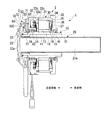
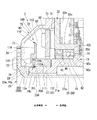
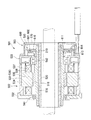
図1は、実施形態におけるエンコーダ付きモータの断面図、図2は、図1の部分拡大図である。
Hereinafter, a motor with an encoder (hollow motor) according to an embodiment of the present invention will be described with reference to the drawings.
FIG. 1 is a sectional view of a motor with an encoder in the embodiment, and FIG. 2 is a partially enlarged view of FIG.
図1に示すように、このエンコーダ付きモータ1は、モータ本体部2と、モータ本体部2の反負荷側(図1中の左側)の外部に配置されたエンコーダ部3と、からなる。
As shown in FIG. 1, the motor 1 with an encoder includes a motor
(モータ本体部)
モータ本体部2は、ステータ34を内装した中空環状のモータケーシング30に、外周にロータマグネット18を装着した中空シャフト10を回転自在に貫通させたブラシレスモータとして構成されている。
なお、モータケーシング30の両端から突出した中空シャフト10の軸方向両端のうち、一端側(図1中の右側)を負荷側とすると共に、他端側(図1中の左側)を反負荷側とする。
(Motor body)
The
Of the axial ends of the
モータケーシング30は、円筒状の中央部ハウジング31と、その円筒状の中央部ハウジング31の軸方向両端開口を塞ぐように連結された負荷側と反負荷側の一対の環状の側部ハウジング32、33と、からなる。モータケーシング30を貫通する中空シャフト10は、負荷側と反負荷側の側部ハウジング32、33の中央開口部(貫通孔)の内周に嵌合された2つのころがり軸受41、42により回転自在に支持されている。
The
反負荷側の側部ハウジング33には、負荷側端部が中央部ハウジング31の反負荷側端部に結合された外周円筒壁33aが設けられている。外周円筒壁33aの反負荷側端部には、径方向内方に垂直に延在する円板壁33bが連設されている。円板壁33bの内周端には、軸方向に平行に負荷側に延在する内周円筒壁33cが連設されている。内周円筒壁33cの負荷側端部には、径方向内方に垂直に折れ曲がる軸受ストッパ壁33dが連設されている。
The
モータケーシング30の内部に収容されたステータ34は、円筒状の中央部ハウジング31の内周に嵌合されたステータコア35と、ステータコア35の各ティースにインシュレータ36を介して巻回されたコイル37と、からなる。ロータマグネット18としてのリングマグネットは、中空シャフト10の外周上の各ティースに対応する位置に保持されている。そして、このように構成されたモータ本体部2は、ステータ34のコイル37に通電することで、中空シャフト10をモータケーシング30に対して回転させることができるようになっている。
A
(中空シャフト)
中空シャフト10は、モータ本体部2に含まれる部分から負荷側に突出した部分までが、大径部11として形成されている。また、モータ本体部2から反負荷側に突出した部分が、小径部12として形成されている。大径部11上には、軸方向の中央に、ロータマグネット18を保持するマグネット保持部13が設けられている。このマグネット保持部13の負荷側には、負荷側のころがり軸受41の嵌合支持部15が設けられている。一方、マグネット保持部13の反負荷側には、径大の軸受ストッパ部14を介して、反負荷側のころがり軸受42の嵌合支持部16が設けられている。
(Hollow shaft)
The
(軸受)
負荷側のころがり軸受41は、中空シャフト10の外周に嵌合されたスリーブ17によって軸方向の位置決めがなされている。
図2に示すように、反負荷側のころがり軸受42は、内輪42aと、外輪42bと、内輪42a及び外輪42b間に挟まれた転動体(玉)42cよりなる。内輪42aは、嵌合支持部16に嵌合された状態で、中空シャフト10の軸受ストッパ部14の端面と中空シャフト10の外周に圧入された軸受内輪固定リング45の端面との間で軸方向に位置決めされている。また、外輪42bは、モータケーシング30の反負荷側の側部ハウジング33の軸受ストッパ壁33dと、側部ハウジング33の内周円筒壁33cに圧入された軸受外輪固定リング46との間で軸方向に位置決めされている。
(bearing)
The load-side rolling bearing 41 is axially positioned by a sleeve 17 fitted to the outer periphery of the
As shown in FIG. 2, the anti-load-side rolling bearing 42 includes an
中空シャフト10の小径部12は、エンコーダ部3の内部に挿入されている。エンコーダ部3には、エンコーダ100と、モータ本体部2を制御する回路基板50と、それらを覆うようにモータケーシング30の側部ハウジング33にボルトで固定されたエンコーダカバー(モータカバー)70と、が設けられている。回路基板50は、ステータ34のコイル37に制御信号を与えるためのもので、側部ハウジング33の円板壁33bの外面に設けられた取付座51に、ボルト52で固定されている。
The
(エンコーダ)
図1、図2に示すように、エンコーダ100は、中空シャフト10の回転角度検出用の光学式エンコーダである。
エンコーダ100は、中空シャフト10の小径部12の外周に取り付けられたエンコーダディスク部材110を備えている。エンコーダディスク部材110は、中空シャフト10の小径部12の外周に、スプライン112を介して嵌合された円筒状のハブ部111を有している。ハブ部111の外周面には、ディスク本体部113が一体成形されている。
(Encoder)
As shown in FIGS. 1 and 2, the
The
ディスク本体部113は、円筒状のハブ部111に対して垂直に設けられた厚肉円板部115の外周側に環状の薄肉部として設けられている。ディスク本体部113の負荷側の面、つまり、回路基板50と軸方向で対向する面は、コード形成面114とされている。
回路基板50には、ディスク本体部113と対向する面で、且つコード形成面114に対応する位置に、発光手段・受光手段を備えたコード読み取り用の光学素子(光学読み取り手段)102が実装されている。
The disk
On the
(エンコーダカバー)
エンコーダカバー70は、径方向中央の開口(後述する袖筒部74の内周面74aで囲われた貫通孔)の周縁を、中空シャフト10における小径部12の反負荷側の端部12a(以下、単に小径部12の端部12aという)に微小隙間を持って対向させた環状カップ型のカバー部材である。エンコーダカバー70は、モータケーシング30に固定されることで、エンコーダ100を収容したカバー内部空間80を外部から覆っている。
(Encoder cover)
The
エンコーダカバー70の外周部には、側部ハウジング33に固定するための固定フランジ71が設けられている。固定フランジ71の内周側には、反負荷側に膨らんだ円錐状のカップ壁72が連設されている。そのカップ壁72の内周側には軸方向に垂直な側壁73が設けられ、その側壁73の径方向の中央に、軸線方向に沿って平行に延在する袖筒部74が連設されている。この袖筒部74は、径方向中央の開口の周縁壁として負荷側に向けて延在しており、その先端側の内周面74aが、小径部12の端部12aの外周面に微小隙間を持って径方向に対向している。
A fixing
(カバーパイプ)
エンコーダカバー70には、小径部12の端部12aを包囲するように気密に且つ着脱自在にカバーパイプ20が連結されている。カバーパイプ20には、エンコーダカバー70に連結する際に、エンコーダカバー70の袖筒部74の内周面74aに外周面23aが嵌合するボス部23が設けられている。このボス部23には、径方向外方へ延出し、エンコーダカバー70の側壁73の外側面に当接した状態で、該外側面に着脱自在に結合されるフランジ部22が設けられている。また、ボス部23には、軸方向に沿って負荷側に向けて延在し、中空シャフト10の内部に非接触で挿通される長い直線パイプ部21が設けられている。
(Cover pipe)
The
直線パイプ部21は、反負荷側から負荷側まで延びており、中空シャフト10の内部に非接触で挿通されることにより、中空シャフト10の内方への露出を制限している。直線パイプ部21の内部は、ケーブル等を挿通させる空間として有効利用できるように、負荷側から反負荷側まで貫通して開放されている。このカバーパイプ21の内部にケーブル等を挿通させることにより、ケーブル等が、回転する中空シャフト10に触れないようにすることができる。
The
また、直線パイプ部21の外周面21bは、中空シャフト10の内周面と対向している。この場合、中空シャフト10の大径部11の内径は、直線パイプ部21の外径に対してかなり大きめに形成されている。従って、負荷側においては、中空シャフト10の内周面と直線パイプ部21の外周面21bとの間に大きな環状のスペースがあいている。
Further, the outer
一方、中空シャフト10の小径部12の内径は、直線パイプ部21の外径に対して僅かに大きめに形成されているだけである。そのため、反負荷側においては、中空シャフト10の内周面と直線パイプ部21の外周面21bとの間に僅かな環状の隙間しかあいていない。そして、この中空シャフト10の小径部12の内周面と直線パイプ部21の外周面21bとの間に確保された環状の僅かな隙間201が、後述する狭流路200の入口となっている。
On the other hand, the inner diameter of the
このように、カバーパイプ20が中空シャフト10の内部に反負荷側から負荷側に向かって挿入されていることにより、カバーパイプ20の外周と中空シャフト10の内周との間に、軸方向に沿った長い環状の隙間が確保されている。これにより、カバー内部空間80に向けて外部から空気が侵入するには、前記の長い隙間を通らなくてはならなくなる。そのため、侵入経路が長くなる分だけ、外部からカバー内部空間80への塵埃等の侵入を防ぐことができる。
Thus, the
しかし、それだけだと、カバーパイプ20と中空シャフト10の間の隙間を通って、塵埃がカバー内部空間80側に運ばれる可能性が依然としてある。特に、中空シャフト10の大径部11側は前記の隙間が大きくなっているので、塵埃等が侵入しやすくなる。
However, with that alone, there is still a possibility that dust will be carried to the cover
そこで、互いに相対回転するエンコーダカバー70及びカバーパイプ20と中空シャフト10の小径部12との間に、ラビリンス効果の高い屈曲形状の狭流路200を確保している。即ち、この狭流路200を設けることによって、中空シャフト10とカバーパイプ20との間の隙間201を通って負荷側から反負荷側に流入し、その上でカバー内部空間80へ侵入しようとする空気の流通を抑制することができるようにしている。
Therefore, a bent
(狭流路)
次に狭流路200の詳細について述べる。
エンコーダカバー70及びカバーパイプ20と中空シャフト10の小径部12との間に確保された狭流路200は、第1の狭流路202と、この第1の狭流路202に連続する第2の狭流路203と、この第2の狭流路203に連続する第3の狭流路204、205とから構成されている。
(Narrow channel)
Next, details of the
A
第1の狭流路202は、小径部12の端部12aと、この端部12aに対して軸方向に対向するカバーパイプ20のボス部23の端面との間に確保された径方向に沿う流路である。第1の狭流路202は、中空シャフト10の小径部12の内周とカバーパイプ20と外周との間の隙間201に連通している。
The first
また、第2の狭流路203は、第1の狭流路202に連通し、且つエンコーダカバー70の袖筒部74の内周面と小径部12の端部12aの外周面との間に確保された軸方向に沿う流路である。従って、中空シャフト10の小径部12の内周とカバーパイプ20の直線パイプ部21の外周との間の隙間201から第1の狭流路202にかけての範囲では、直角に流路が屈曲している。また、第1の狭流路202から第2の狭流路203にかけての範囲でも、直角に流路が屈曲している。
The second
また、第2の狭流路203に連通する第3の狭流路204、205は、エンコーダディスク部材110のハブ部111の反負荷側の端面に形成されたL型の凹部111aに、エンコーダカバー70の袖筒部74の先端74bが挿入されることで、袖筒部74の外面と凹部111aの内面との間に形成されている。
Further, the third
(ロック機構)
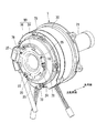
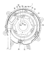
次に、エンコーダカバー70とエンコーダカバー70に着脱自在に結合されるカバーパイプ20のフランジ部22との間に設けられたロック機構について、図3〜図8を参照して説明する。
(Lock mechanism)
Next, a lock mechanism provided between the
ロック機構は、カバーパイプ20をエンコーダカバー70の側壁73の外側面に対して軸方向に抜け止めロックし且つ周方向に回転止めロックする回転スライド式ロック機構90として構成されている。この回転スライド式ロック機構90は、ボス部23の外周を袖筒部74の内周74aに嵌合させながら、フランジ部22を所定の回転位置でエンコーダカバー70の側壁73の外側面に当接させ、その状態で、フランジ部22を所定方向に回転させることで、カバーパイプ20をエンコーダカバー70に対して軸方向に抜け止めロックし且つ周方向に回転止めロックするものである。
The lock mechanism is configured as a rotary slide
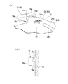
具体的に説明すると、図3〜図8に示すように、この回転スライド式ロック機構90は、フランジ部22の外周縁に周方向に間隔をおいて一定ピッチで配置され、且つそれぞれが径方向外向きに突設された複数のロック板24と、エンコーダカバー70の側壁73の外側面に前記ロック板24に対応して突設された複数のロック枠76との組み合わせとして構成されている。
More specifically, as shown in FIGS. 3 to 8, the rotary slide
フランジ部22に設けられた各ロック板24は、図6に拡大して示すように、フランジ部22の外周縁から径方向外向きに突出し外周縁が円弧状に形成された基部24aと、該基部24aの周方向一端(カバーパイプ20(ロック板24)の回転方向と反対側端)から周方向一方側(カバーパイプ20(ロック板24)の回転方向と反対側)に延設されているロックアーム24bと、ロックアーム24bの内周縁とフランジ部22の外周縁との間に確保された撓み空間24cと、ロックアーム24bの先端部の外周縁に突設されロック突起24dと、を備えている。
ロックアーム24bは、外周縁が基部24aの外周縁と連続した円弧状に形成され、径方向に撓み可能とされている。撓み空間24cは、ロックアーム24bの撓みを許容するための空間である。
As shown in an enlarged view in FIG. 6, each
The
一方、エンコーダカバー70に設けられた各ロック枠76は、前記ロック板24がエンコーダカバー70の側壁73の外側面に当接した状態で周方向他方側に回転したとき、ロック板24の基部24aを受け入れる溝部76bを背後に有するように、断面略L字状に形成されている。すなわち、各ロック枠76は、エンコーダカバー70の側壁73から立ち上がるガイド壁76cと、このガイド壁76cの先端における周方向他方側から直交する方向に延出する係止壁76aとが一体成形されたものである。そして、エンコーダカバー70の側壁73、係止壁76a及びガイド壁76cによって、ロック板24の基部24aを受け入れる溝部76bが形成される。
On the other hand, each
係止壁76aは、溝部76bにロック板24の基部24aを受け入れているときにロック板24の軸方向への抜けを阻止する役割を有する。
ガイド壁76cは、ロック板24が周方向他方側に回転して、ロック板24の基部24aが溝部76bに受け入れられる際にロックアーム24bの外周縁が摺接し、且つ、ロックアーム24bのロック突起24dが摺接することにより、ロックアーム24bを撓ませる。また、ガイド壁76cの内周には、周方向一端側にロック凹部76dが形成されている。ロック凹部76dは、ロックアーム24bのロック突起24dと係合することで、ロック板24を周方向に係止する。
The locking
The
また、回転スライド式ロック機構90は、図4や図7に示すように、フランジ部22の外周縁に周方向に間隔をおいて配置され、且つそれぞれが径方向外向きに突設された複数のストッパ片25と、エンコーダカバー70の側壁73の外側面に突設されたストッパ凸部78と、を備えている。
Further, as shown in FIGS. 4 and 7, the rotary slide
ストッパ凸部78は、ロック板24をエンコーダカバー70の側壁73に当接させた状態でロック枠76に係合させるためにフランジ部22を周方向他方側(図7中矢印R側)に回転させる際に、ストッパ片25と係合することで、フランジ部22の周方向一方側(図7中矢印Rと反対側)への回転を阻止する。また、ストッパ凸部78は、フランジ部22を周方向他方側に回転させて、ロック板24をロック枠76に係合させたとき、ロック板24の基部24aと係合することで、フランジ部22の周方向一方側へのそれ以上の回転を阻止する。
The
(ロック機構の作用)
カバーパイプ20を、モータ本体部2に装着したエンコーダカバー70に取り付ける際には、図3に示すように、カバーパイプ20を矢印X方向に移動して、直線パイプ部21の先端をエンコーダカバー70の中央開口に挿入し、モータ本体部2の中空シャフト10の内部に貫通させる。
(Operation of locking mechanism)
When the
その際、図2に示すように、カバーパイプ20のボス部23の外周面23aを、エンコーダカバー70の袖筒部74の内周面74aに嵌合させながら、直線パイプ部21の先端をエンコーダカバー7の中央開口に挿入する。そして、図4及び図5に示すように、カバーパイプ20のフランジ部22をエンコーダカバー70の側壁73の外側面に当接させる。このとき、カバーパイプ20側のロック板24とエンコーダカバー70側のロック枠76とが重ならない回転位置でフランジ部22をエンコーダカバー70の側壁73の外側面に当接させる。
At this time, as shown in FIG. 2, the end of the
次に、その状態で、フランジ部22を図7の矢印R方向に回転させる。この際、矢印R方向と反対方向にフランジ部22を回転させようとすると、図5に示すように、ストッパ凸部78にストッパ片25が衝突するので、ロックのための回転方向を間違わずに組立作業を行うことができる。
Next, in this state, the
フランジ部22を図7の矢印R方向に回転させると、図8にも示すように、フランジ部22側のロック板24の基部24aが、エンコーダカバー70側のロック枠76の溝部76bに入り込む。それと同時に、ロック板24のロックアーム24bの外周縁がガイド壁76cの内周縁に摺動し、ロック突起24dがガイド壁76cの内周縁に摺動するようになった段階で、ロックアーム24bが径方向内方に撓む。
When the
そして、更にフランジ部22を同じ方向に回転させると、ロックアーム24bが撓みから復帰しながら、ロック突起24dが、ガイド壁76cのロック凹部76dに係合する。これにより、ロック突起24dとロック凹部76dの係合される(ロック枠76とロック板24とがスナップフィット固定される)ことによって、フランジ部22が回転ロックされる。同時に、係止壁76aにロック板24の基部24aが係止されることで、フランジ部22が軸方向に抜け止めロックされる。
When the
また、このロック状態になったところで、フランジ部22に設けたロック板24の基部24aがストッパ片25に当たることで、フランジ部22が余計に回転しないように止められるので、ロック作業が容易にできるようになる。
以上のように、カバーパイプ20の脱着ができるので、長いカバーパイプ20の場合であっても、エンコーダカバー70やカバーパイプ20の取り扱いがやりやすくなる。
Further, when the locked state is reached, the
As described above, since the
(狭流路の作用)
次に、外部からエンコーダカバー70のカバー内部空間80に塵埃が入り込みにくくなる点について説明する。
(Operation of narrow flow path)
Next, the point that dust hardly enters the cover
まず、外部から異物がエンコーダカバー70の内部に入り込む経路は、カバーパイプ20と中空シャフト10との間の隙間を通って狭流路200に至り、狭流路200を通ってカバー内部空間80に到達する経路である。しかし、狭流路200の入口にまで至ったとしても、狭流路200が屈曲したラビリンスとして存在するので、カバー内部空間80への塵埃等の侵入が確実に防止される。従って、エンコーダ100の特にディスク本体部113に塵埃等が付着して検出精度が落ちたり、その結果、エンコーダディスク部材110のコード成形面114や光学素子102に油分が付着したりする等、モータ本体部2の誤動作が起きたりするのを防ぐことができる。
First, a path through which foreign matter enters the inside of the
また、エンコーダカバー70及びカバーパイプ20と中空シャフト10の反負荷側の端部12aとの間に、塵埃等の流入を阻止する屈曲形状の狭流路200を確保しているので、中空シャフト10の内周とカバーパイプ20の外周との間の隙間を全長に渡って極力狭くする必要がない。よって、本実施形態のように、特に負荷側において中空シャフト10の内周とカバーパイプ20の外周との間の隙間を余裕を持って設定することができる。それにより、寸法管理が容易になると共に、片持ち支持するカバーパイプ20の長さを長くしたりすることも容易にできるようになる。
Further, since the bent
また、互いに相対回転するエンコーダカバー70及びカバーパイプ20と中空シャフト10の反負荷側の端部12aとの間に狭流路200を確保するので、特に部品同士の対向面に凹部や凸部を設ける面倒を要することがない。このため、部品の外形形状の単純な組み合わせで狭流路200を構成することができる。従って、凹部や凸部を形成するような面倒な微細加工が不要となり、加工コストの低減を図ることができる。
Moreover, since the
このように構成することで、エンコーダカバーに対するカバーパイプの脱着が容易にできるようになる。また、ボス部の外周をエンコーダカバーの袖筒部の内周に嵌合させた状態でロックするので、片持ちであってもカバーパイプを安定支持することができる。 With this configuration, the cover pipe can be easily attached to and detached from the encoder cover. Further, since the outer periphery of the boss portion is locked in a state of being fitted to the inner periphery of the sleeve tube portion of the encoder cover, the cover pipe can be stably supported even if it is cantilevered.
なお、本発明は上述の実施形態に限られるものではなく、本発明の趣旨を逸脱しない範囲において、上述の実施形態に種々の変更を加えたものを含む。
例えば、上述の実施形態では、中空モータとしてエンコーダ付きモータ1を例に説明したが、これに限られるものではなく、エンコーダが取り付けられていない中空モータにも、同様の効果を奏することができる。すなわち、モータ内部への塵埃等の侵入を防ぐことにより、塵埃等によるコイル37の短絡等を防ぎ、モータを安定動作させることができる。
The present invention is not limited to the above-described embodiment, and includes various modifications made to the above-described embodiment without departing from the spirit of the present invention.
For example, in the above-described embodiment, the motor 1 with an encoder has been described as an example of the hollow motor. However, the present invention is not limited to this, and the same effect can be obtained for a hollow motor to which no encoder is attached. That is, by preventing dust and the like from entering the motor, it is possible to prevent the
また、上述の実施形態では、エンコーダカバー70及びカバーパイプ20に回転スライド式ロック機構90を設け、エンコーダカバー70にカバーパイプ20を固定するにあたって、ロック枠76とロック板24とをスナップフィット固定させる場合について説明した。しかしながら、これに限られるものではなく、エンコーダカバー70にカバーパイプ20を取り付けるためにさまざまな構造を適用することができる。
例えば、エンコーダカバー70の側壁73と係止壁76aとの間の溝部76bの幅(図6(b)参照)を、ロック板24の板厚よりも若干狭く設定し、エンコーダカバー70の側壁73と係止壁76aとの間に、ロック板24を圧入することにより、ロック板24を周方向に係止するように構成してもよい。また、エンコーダカバー70にカバーパイプ20のフランジ部22をボルト等を用いて締結固定してもよい。
In the above-described embodiment, the
For example, the width of the
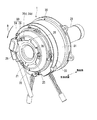
(他の実施形態)
また、図9に示すように、狭流路200の途中に、狭流路200の断面積を制限する流路制限部材(例えば、Oリング230)を介装してもよい。このように構成することで、エンコーダカバー70内部への塵埃等の侵入を、さらに確実に防ぐことができる。
(Other embodiments)
Further, as shown in FIG. 9, a flow path limiting member (for example, an O-ring 230) that limits the cross-sectional area of the
1…エンコーダ付きモータ(中空モータ)
2…モータ本体部
3…エンコーダ部
10…中空シャフト
12a…反負荷側の端部
18…ロータマグネット
20…カバーパイプ
21…直線パイプ部
22…フランジ部
23…ボス部
23a…外周面
24…ロック板
24a…基部
24b…ロックアーム
24d…ロック突起
25…ストッパ片
30…モータケーシング
34…ステータ
37…コイル
70…エンコーダカバー(モータカバー)
73…側壁
74…袖筒部
74a…内周面
74b…先端
76…ロック枠
76a…係止壁
76b…溝部
76c…ガイド壁
76d…ロック凹部
78…ストッパ凸部
80…カバー内部空間
90…回転スライド式ロック機構
100…エンコーダ
102…光学素子(光学読み取り手段)
110…エンコーダディスク部材
111…ハブ部
111a…凹部
113…ディスク本体部
114…コード形成面
200…狭流路
201…中空シャフトの内周と前記カバーパイプの外周との間の隙間
202…第1の狭流路
203…第2の狭流路
204,205…第3の狭流路
230…Oリング(流路制限部材)
1. Motor with encoder (hollow motor)
DESCRIPTION OF
73 ...
DESCRIPTION OF
Claims (7)
前記モータケーシングの前記反負荷側の端部に配置され、径方向中央の開口の周縁を前記中空シャフトの前記反負荷側の端部に微小隙間を持って対向させ、その状態で前記モータケーシングに固定されることで、前記モータケーシングの前記反負荷側の端部を外部から覆う環状のモータカバーと、
前記モータカバーに、前記中空シャフトの前記反負荷側の端部を包囲するように気密に連結され、前記中空シャフトの内部に非接触で挿通されることで、前記負荷側においては、前記中空シャフトの内周と前記カバーパイプの外周との間に環状のスペースが形成されて、前記中空シャフトの露出を制限するカバーパイプと、を備え、
互いに相対回転する前記モータカバー及びカバーパイプと前記中空シャフトの前記反負荷側の端部との間に、前記中空シャフトの前記内周と前記カバーパイプの前記外周との間の隙間を通って前記負荷側から前記反負荷側に流入し、その上で前記モータカバーのカバー内部空間へ侵入しようとする空気の流通を抑制する屈曲形状を有すると共に前記中空シャフトの前記内周と前記カバーパイプの前記外周との間の前記隙間より狭く形成され、前記モータケーシングの外部と連通する狭流路を確保したことを特徴とする中空モータ。 A hollow shaft with a rotor magnet mounted on the outer periphery is rotatably passed through a hollow annular motor casing with a built-in stator, and one end side of the axial ends of the hollow shaft protruding from both ends of the motor casing is defined as a load side. And the other end side as the anti-load side, and energizing the coil of the stator, thereby rotating the hollow shaft relative to the motor casing,
The motor casing is disposed at the end on the opposite side of the motor casing, and the peripheral edge of the central opening in the radial direction is opposed to the end on the opposite side of the hollow shaft with a minute gap. By being fixed, an annular motor cover that covers the opposite end of the motor casing from the outside, and
The motor cover is hermetically connected so as to surround the end portion of the hollow shaft on the side opposite to the load, and is inserted into the hollow shaft in a non-contact manner. An annular space is formed between the inner periphery of the cover pipe and the outer periphery of the cover pipe, and the cover pipe restricts the exposure of the hollow shaft.
Between the non-load-side end portion of the motor cover and the cover pipe and the hollow shaft to rotate relative to each other, wherein through the gap between the inner periphery of the hollow shaft and the outer periphery of the cover pipe It has a bent shape that suppresses the flow of air that flows from the load side to the anti-load side and then enters the cover internal space of the motor cover, and the inner periphery of the hollow shaft and the cover pipe A hollow motor characterized in that a narrow flow path is formed which is narrower than the gap between the outer periphery and communicates with the outside of the motor casing .
前記カバーパイプは、
前記モータカバーに連結する際に、前記モータカバーの前記袖筒部の内周面に外周面が嵌合するボス部と、
該ボス部から径方向外方へ延出し前記モータカバーの外側面に当接した状態で該モータカバーの外側面に結合されるフランジ部と、
前記ボス部から軸方向に沿って前記負荷側に向けて延在し前記中空シャフトの内部に非接触で挿通される直線パイプ部と、を有し、
前記狭流路は、
前記中空シャフトの前記反負荷側の端面と、該端面に対して軸方向に対向する前記カバーパイプの前記ボス部の端面との間に確保された径方向に沿う第1の狭流路と、
該第1の狭流路に連続し且つ前記モータカバーの前記袖筒部の内周面と前記中空シャフトの前記反負荷側の端部の外周面との間に確保された軸方向に沿う第2の狭流路と、を備えており、
前記中空シャフトと前記カバーパイプの直線パイプ部との間の隙間から前記第1の狭流路にかけて直角に流路が屈曲し、前記第1の狭流路から第2の狭流路にかけて流路が屈曲していることを特徴とする請求項1に記載の中空モータ。 The motor cover, as a peripheral wall of the opening in the center in the radial direction, extends toward the load side, and an inner peripheral surface thereof is opposed to an outer peripheral surface of the end portion on the opposite side of the hollow shaft with a gap. Has a cylindrical sleeve portion to
The cover pipe is
When connecting to the motor cover, a boss part whose outer peripheral surface is fitted to the inner peripheral surface of the sleeve tube part of the motor cover;
A flange portion extending radially outward from the boss portion and coupled to the outer surface of the motor cover in a state of being in contact with the outer surface of the motor cover;
A straight pipe portion extending from the boss portion along the axial direction toward the load side and inserted through the hollow shaft in a non-contact manner;
The narrow channel is
A first narrow flow path along a radial direction secured between the end surface of the hollow shaft on the side opposite to the load and the end surface of the boss portion of the cover pipe facing the end surface in the axial direction;
A second axial line that is continuous with the first narrow flow path and is secured between the inner peripheral surface of the sleeve tube portion of the motor cover and the outer peripheral surface of the end portion on the opposite side of the hollow shaft. A narrow flow path, and
The flow path bends at right angles from the gap between the hollow shaft and the straight pipe portion of the cover pipe to the first narrow flow path, and from the first narrow flow path to the second narrow flow path. The hollow motor according to claim 1, wherein the motor is bent.
前記モータカバーは、前記モータケーシングの前記反負荷側の端部及び前記エンコーダを外部から覆うように形成されており、
前記エンコーダは、
前記中空シャフトの前記反負荷側の端部の外周に該中空シャフトと一体回転するように嵌合されたハブ部を有するエンコーダディスク部材を備え、
前記エンコーダディスク部材のハブ部に形成された凹部に、前記モータカバーの前記袖筒部の先端が挿入されることで、前記袖筒部の外面と前記凹部の内面との間に、前記狭流路の一部として、前記第2の狭流路に連続する第3の狭流路が確保されていることを特徴とする請求項2に記載の中空モータ。 An encoder disposed outside the motor casing on the opposite side of the load and detecting a rotation angle of the hollow shaft relative to the motor casing;
The motor cover is formed so as to cover the opposite end of the motor casing and the encoder from the outside,
The encoder is
An encoder disk member having a hub portion fitted so as to rotate integrally with the hollow shaft on an outer periphery of the end portion on the opposite side of the hollow shaft;
The tip of the sleeve tube portion of the motor cover is inserted into the recess formed in the hub portion of the encoder disk member, so that the narrow flow path is between the outer surface of the sleeve tube portion and the inner surface of the recess. 3. The hollow motor according to claim 2, wherein a third narrow flow path continuous to the second narrow flow path is secured as a part.
前記フランジ部の外周縁に周方向に間隔をおいて配置され且つそれぞれが径方向外向きに突設された複数のロック板と、前記モータカバーの外側面に前記ロック板に対応して突設された複数のロック枠との組み合わせとして構成され、
前記フランジ部に設けられた各ロック板は、
前記フランジ部の外周縁から径方向外向きに突出し外周縁が円弧状に形成された基部と、
該基部の周方向一端から周方向一方側に延設され、外周縁が前記基部の外周縁と連続した円弧状に形成され、径方向に撓み可能とされたロックアームと、
該ロックアームの先端部の外周縁に突設されロック突起と、を有し、
前記モータカバーに設けられた各ロック枠は、
前記ロック板が前記モータカバーの外側面に当接した状態で周方向他方側に回転したとき、前記ロック板の前記基部を受け入れる溝部を背後に有すると共に、該溝部に前記ロック板の前記基部を受け入れているときに前記ロック板の軸方向への抜けを阻止する係止壁と、
前記ロック板が周方向他方側に回転して、前記ロック板の前記基部が前記溝部に受け入れられる際に前記ロックアームの外周縁が摺接し、且つ、前記ロックアームのロック突起が摺接することにより、前記ロックアームを撓ませるガイド壁と、
該ガイド壁の内周に形成され、前記ロックアームのロック突起と係合することで、前記ロック板を周方向に係止するロック凹部と、を有していることを特徴とする請求項4に記載の中空モータ。 The rotary slide type locking mechanism is
A plurality of lock plates disposed on the outer peripheral edge of the flange portion at intervals in the circumferential direction and projecting radially outward, and projecting from the outer surface of the motor cover corresponding to the lock plate Configured as a combination with multiple lock frames,
Each lock plate provided in the flange portion,
A base portion that protrudes radially outward from the outer peripheral edge of the flange portion and the outer peripheral edge is formed in an arc shape;
A lock arm extending from one end in the circumferential direction of the base to one side in the circumferential direction, an outer peripheral edge formed in an arc shape that is continuous with the outer peripheral edge of the base, and capable of bending in the radial direction;
A lock protrusion protruding from the outer peripheral edge of the tip of the lock arm,
Each lock frame provided on the motor cover,
When the lock plate is rotated to the other side in the circumferential direction while being in contact with the outer surface of the motor cover, the lock plate has a groove portion for receiving the base portion of the lock plate in the back, and the base portion of the lock plate is disposed in the groove portion. A locking wall that prevents the locking plate from coming off in the axial direction when receiving,
When the lock plate rotates to the other side in the circumferential direction, when the base portion of the lock plate is received in the groove portion, the outer peripheral edge of the lock arm is in sliding contact, and the lock protrusion of the lock arm is in sliding contact A guide wall for bending the lock arm;
5. A lock recess formed on an inner periphery of the guide wall and engaged with a lock protrusion of the lock arm to lock the lock plate in a circumferential direction. The hollow motor described in 1.
前記フランジ部の外周縁に周方向に間隔をおいて配置され且つそれぞれが径方向外向きに突設された複数のストッパ片と、
前記ロック板を前記モータカバーの外側面に当接させた状態で前記ロック枠に係合させるために前記フランジ部を周方向他方側に回転させる際に、前記ストッパ片と係合することで、前記フランジ部の周方向一方側への回転を阻止し、且つ、前記フランジ部を周方向他方側に回転させて、前記ロック板を前記ロック枠に係合させたとき、前記ロック板の前記基部と係合することで、前記フランジ部の周方向一方側へのそれ以上の回転を阻止するストッパ凸部と、
を含むことを特徴とする請求項5に記載の中空モータ。 The rotary slide type locking mechanism is
A plurality of stopper pieces arranged on the outer peripheral edge of the flange portion at intervals in the circumferential direction and each projecting radially outward;
By engaging the stopper piece when rotating the flange portion to the other side in the circumferential direction in order to engage the lock frame with the lock plate being in contact with the outer surface of the motor cover, When the flange portion is prevented from rotating to one side in the circumferential direction, and the flange portion is rotated to the other side in the circumferential direction to engage the lock plate with the lock frame, the base portion of the lock plate A stopper projection that prevents further rotation of the flange portion toward one side in the circumferential direction by engaging with
The hollow motor according to claim 5, comprising:
Priority Applications (1)
| Application Number | Priority Date | Filing Date | Title |
|---|---|---|---|
| JP2014244398A JP6401034B2 (en) | 2014-12-02 | 2014-12-02 | Hollow motor |
Applications Claiming Priority (1)
| Application Number | Priority Date | Filing Date | Title |
|---|---|---|---|
| JP2014244398A JP6401034B2 (en) | 2014-12-02 | 2014-12-02 | Hollow motor |
Publications (2)
| Publication Number | Publication Date |
|---|---|
| JP2016111740A JP2016111740A (en) | 2016-06-20 |
| JP6401034B2 true JP6401034B2 (en) | 2018-10-03 |
Family
ID=56125164
Family Applications (1)
| Application Number | Title | Priority Date | Filing Date |
|---|---|---|---|
| JP2014244398A Active JP6401034B2 (en) | 2014-12-02 | 2014-12-02 | Hollow motor |
Country Status (1)
| Country | Link |
|---|---|
| JP (1) | JP6401034B2 (en) |
Cited By (1)
| Publication number | Priority date | Publication date | Assignee | Title |
|---|---|---|---|---|
| CN111934464A (en) * | 2020-08-18 | 2020-11-13 | 绍兴集知汇信息科技有限公司 | Improved motor |
Families Citing this family (6)
| Publication number | Priority date | Publication date | Assignee | Title |
|---|---|---|---|---|
| KR102564743B1 (en) * | 2018-05-11 | 2023-08-08 | 엘지이노텍 주식회사 | Motor |
| CN109450146B (en) * | 2018-12-13 | 2023-10-27 | 歌尔股份有限公司 | Rotary motor |
| JP7512560B2 (en) * | 2019-06-14 | 2024-07-09 | ニデックドライブテクノロジー株式会社 | Rotary Actuator and Robot |
| JP6937967B1 (en) * | 2020-12-01 | 2021-09-22 | 三菱電機株式会社 | Rotating machine |
| JP7674922B2 (en) * | 2021-06-15 | 2025-05-12 | ニデック株式会社 | Motor |
| JPWO2023135688A1 (en) * | 2022-01-12 | 2023-07-20 |
Family Cites Families (2)
| Publication number | Priority date | Publication date | Assignee | Title |
|---|---|---|---|---|
| JP2007288870A (en) * | 2006-04-13 | 2007-11-01 | Yaskawa Electric Corp | Hollow actuator |
| JP2009261149A (en) * | 2008-04-17 | 2009-11-05 | Mitsuba Corp | Brushless motor |
-
2014
- 2014-12-02 JP JP2014244398A patent/JP6401034B2/en active Active
Cited By (1)
| Publication number | Priority date | Publication date | Assignee | Title |
|---|---|---|---|---|
| CN111934464A (en) * | 2020-08-18 | 2020-11-13 | 绍兴集知汇信息科技有限公司 | Improved motor |
Also Published As
| Publication number | Publication date |
|---|---|
| JP2016111740A (en) | 2016-06-20 |
Similar Documents
| Publication | Publication Date | Title |
|---|---|---|
| JP6401034B2 (en) | Hollow motor | |
| JP5085568B2 (en) | Shaft support device for electric motor and its mounting method | |
| KR101591320B1 (en) | Rotary connector with sensor assembled thereto | |
| JP6385347B2 (en) | mechanical seal | |
| CN109923029B (en) | Torque index sensor and steering device including the same | |
| JPWO2018147012A1 (en) | motor | |
| JP6382913B2 (en) | Electric motor with labyrinth | |
| CN109923769B (en) | Rotational position detecting device | |
| JP2005256880A (en) | Bearing with sensor | |
| EP1850094A2 (en) | Rotation sensor | |
| CN107533966B (en) | Motor with hydrostatic seal | |
| JP2014180107A (en) | Dynamo-electric machine | |
| JP4804843B2 (en) | Motor with magnetic encoder | |
| JP5852162B2 (en) | Rotating speed detector for motorcycle | |
| JP2000065847A (en) | Rolling bearing unit with rotation speed detector | |
| JP2013007411A (en) | Sliding bearing device with rotation detection function | |
| JP2006207750A (en) | Bearing with sensor and bearing device | |
| JP7153998B2 (en) | motor | |
| EP3640579B1 (en) | Rotation detection device | |
| JP4851381B2 (en) | Rolling bearing with rotation sensor | |
| JP2005106653A (en) | Rotation amount detection device | |
| KR102865159B1 (en) | Motor | |
| WO2019065717A1 (en) | Magnetic rotation sensor, bearing with magnetic rotation sensor, and method for attaching actuator and magnetic rotation sensor | |
| JP4963928B2 (en) | Bearing with sensor | |
| CN116025634A (en) | Sensor bearing units and associated equipment |
Legal Events
| Date | Code | Title | Description |
|---|---|---|---|
| A621 | Written request for application examination |
Free format text: JAPANESE INTERMEDIATE CODE: A621 Effective date: 20170403 |
|
| A977 | Report on retrieval |
Free format text: JAPANESE INTERMEDIATE CODE: A971007 Effective date: 20180209 |
|
| A131 | Notification of reasons for refusal |
Free format text: JAPANESE INTERMEDIATE CODE: A131 Effective date: 20180220 |
|
| A521 | Request for written amendment filed |
Free format text: JAPANESE INTERMEDIATE CODE: A523 Effective date: 20180412 |
|
| TRDD | Decision of grant or rejection written | ||
| A01 | Written decision to grant a patent or to grant a registration (utility model) |
Free format text: JAPANESE INTERMEDIATE CODE: A01 Effective date: 20180807 |
|
| A61 | First payment of annual fees (during grant procedure) |
Free format text: JAPANESE INTERMEDIATE CODE: A61 Effective date: 20180906 |
|
| R150 | Certificate of patent or registration of utility model |
Ref document number: 6401034 Country of ref document: JP Free format text: JAPANESE INTERMEDIATE CODE: R150 |
|
| R250 | Receipt of annual fees |
Free format text: JAPANESE INTERMEDIATE CODE: R250 |
|
| R250 | Receipt of annual fees |
Free format text: JAPANESE INTERMEDIATE CODE: R250 |
|
| R250 | Receipt of annual fees |
Free format text: JAPANESE INTERMEDIATE CODE: R250 |
|
| R250 | Receipt of annual fees |
Free format text: JAPANESE INTERMEDIATE CODE: R250 |
|
| R250 | Receipt of annual fees |
Free format text: JAPANESE INTERMEDIATE CODE: R250 |