JP6388273B2 - Bus duct plug-in hole protection structure - Google Patents

Bus duct plug-in hole protection structure Download PDF

Info

Publication number
JP6388273B2
JP6388273B2 JP2013228723A JP2013228723A JP6388273B2 JP 6388273 B2 JP6388273 B2 JP 6388273B2 JP 2013228723 A JP2013228723 A JP 2013228723A JP 2013228723 A JP2013228723 A JP 2013228723A JP 6388273 B2 JP6388273 B2 JP 6388273B2
Authority
JP
Japan
Prior art keywords
plug
hole
bus duct
shutter member
shutter
Prior art date
Legal status (The legal status is an assumption and is not a legal conclusion. Google has not performed a legal analysis and makes no representation as to the accuracy of the status listed.)
Active
Application number
JP2013228723A
Other languages
Japanese (ja)
Other versions
JP2014103845A5 (en
JP2014103845A (en
Inventor
吉田 稔
稔 吉田
幸彦 山田
幸彦 山田
Current Assignee (The listed assignees may be inaccurate. Google has not performed a legal analysis and makes no representation or warranty as to the accuracy of the list.)
Kyodo Ky Tec Corp
Original Assignee
Kyodo Ky Tec Corp
Priority date (The priority date is an assumption and is not a legal conclusion. Google has not performed a legal analysis and makes no representation as to the accuracy of the date listed.)
Filing date
Publication date
Application filed by Kyodo Ky Tec Corp filed Critical Kyodo Ky Tec Corp
Priority to JP2013228723A priority Critical patent/JP6388273B2/en
Publication of JP2014103845A publication Critical patent/JP2014103845A/en
Publication of JP2014103845A5 publication Critical patent/JP2014103845A5/en
Application granted granted Critical
Publication of JP6388273B2 publication Critical patent/JP6388273B2/en
Active legal-status Critical Current
Anticipated expiration legal-status Critical

Links

Images

Description

発明の詳細な説明Detailed Description of the Invention

本発明は、バスダクトプラグインホール保護構造に関し、例えば、バスダクトに設けられたプラグインホールの保護構造に関する。  The present invention relates to a bus duct plug-in hole protection structure, for example, a plug-in hole protection structure provided in a bus duct.

従来、バスダクトのプラグインホールの保護構造として、特許文献1に示すようなプラグイン接続部保護装置がある。このプラグイン接続部保護装置では、プラグイン接続部の回りに電気絶縁物製のカバーを取り付け、そのカバーのプラグイン端子挿入口に一対の弾性唇片を対向するように設けて常時密着させるようにしており、プラグイン器具の接続端片を挿し込む際に弾性唇片が押し広げられることで開口し、接続端片を引き出す際に弾性唇片が元に戻ることで閉塞するようになされている。これにより、プラグインホール内に塵埃が入ることを防ぐようになっている。  Conventionally, as a protection structure for a plug-in hole of a bus duct, there is a plug-in connection part protection device as shown in Patent Document 1. In this plug-in connection protection device, a cover made of an electric insulator is attached around the plug-in connection, and a pair of elastic lip pieces are provided so as to face each other at the plug-in terminal insertion port of the cover so that they always adhere to each other. The elastic lip piece is opened when the connecting end piece of the plug-in device is inserted and opened, and when the connecting end piece is pulled out, the elastic lip piece is returned to the original position to close it. Yes. This prevents dust from entering the plug-in hole.

実公昭49−20295号公報Japanese Utility Model Publication No. 49-20295

しかしながら、上述した特許文献1に記載されたプラグインホール保護構造は、塵埃といった空気中を浮遊する程度の軽い物質の侵入を防ぐ目的であるため、弾性力によって全体が変形する電気絶縁物製樹脂のカバー(弾性唇片)によってプラグインホールを保護できるようになされているが、電気幹線の全体に多くのプラグインホールを予め設けているバスダクトにおいて、例えば作業者を感電等から保護することを目的とした場合の保護強度としては不安があるという技術的課題を有している。  However, since the plug-in hole protection structure described in Patent Document 1 described above is for the purpose of preventing the entry of a light substance that floats in the air, such as dust, an electrically insulating resin that is deformed entirely by elasticity. The cover (elastic lip piece) can be used to protect the plug-in hole. In the bus duct in which many plug-in holes are provided in advance on the entire electric trunk line, for example, the operator can be protected from electric shock. There is a technical problem that there is anxiety about the protection strength when it is aimed.

この点を解決するため、上述した特許文献1における電気絶縁物製樹脂カバーを厚くしたり、剛性の強い材料に変更したりすることが考えられるが、その分だけ弾性力が強くなるため、プラグイン器具の挿入に支障が出るという問題がある。すなわち、特許文献1に記載されたプラグインホール保護構造では、保護の強固さとプラグイン器具の挿入のし易さ(施工性)との間にトレードオフの関係があるため、作業者の感電等を防ぐことを目的とした強固な保護とプラグイン時の施工性との両立が困難である。  In order to solve this point, it is conceivable to increase the thickness of the electrical insulating resin cover in Patent Document 1 described above or to change the material to a material having high rigidity. There is a problem that the insertion of the in-instrument is hindered. That is, in the plug-in hole protection structure described in Patent Document 1, there is a trade-off relationship between the strength of protection and the ease of insertion of plug-in equipment (constructability). It is difficult to achieve both strong protection aimed at preventing the damage and workability during plug-in.

本発明は、上記技術的課題に鑑みてなされたものであり、バスダクトのプラグインホールにおいて、作業者の感電等を防ぐための強固な保護とプラグイン時の施工性とを両立可能な保護構造を提供することを目的とする。  The present invention has been made in view of the above technical problem, and in a plug-in hole of a bus duct, a protective structure capable of achieving both strong protection for preventing an electric shock of an operator and workability during plug-in. The purpose is to provide.

上記技術的課題を解決するためになされた本発明は、バスダクトのハウジングに設けられたプラグインホールに対してプラグイン装置を着脱する際のバスダクトプラグインホール保護構造において、前記バスダクトには、前記プラグインホールを開閉可能に閉塞するシャッタ部材と、前記プラグインホールを閉塞する方向に前記シャッタ部材を付勢するバネ部材とが設けられ、前記プラグイン装置には、前記プラグインホールへ前記プラグイン装置を近づける動作に応じ、前記シャッタ部材を開放方向へ動かす(スライドさせる、回動させる、等)シャッタ開放部が形成されていることを特徴としている。  The present invention made to solve the above technical problem is a bus duct plug-in hole protection structure when a plug-in device is attached to and detached from a plug-in hole provided in a housing of a bus duct. A shutter member that closes the plug-in hole so as to be openable and closable and a spring member that urges the shutter member in a direction to close the plug-in hole are provided, and the plug-in device includes the plug into the plug-in hole. A shutter opening portion is formed which moves (slides, rotates, etc.) the shutter member in the opening direction in accordance with the operation of bringing the in-apparatus closer.

このように、本発明のバスダクトプラグインホール保護構造では、プラグインホールを閉塞するシャッタ部材とシャッタ部材を閉塞方向に付勢するバネ部材とを別部材によって形成しているため、シャッタ部材の強度とバネ部材の強度とを別個に設定することができる。すなわち、本発明によれば、プラグイン時の施工性を悪化させることなくシャッタ部材の強度を上げて強固な保護構造を提供することができるため、バスダクトのプラグインホールにおいて、作業者の感電等を防ぐための強固な保護とプラグイン時の施工性とを両立可能な保護構造を提供することができる。
また、本発明は、電気幹線を形成し少なくとも1つの導体を有するバスダクトのハウジングに設けられたプラグインホールに対してプラグイン装置の接触子を挿入しつつ該導体に接続する際のバスダクトプラグインホール保護構造において、前記バスダクトには、前記プラグインホールを開閉可能に閉塞する扉部材が設けられ、前記プラグイン装置には、前記プラグインホールへ前記プラグイン装置を近づける動作に応じ、前記扉部材を開方向へ動かす扉開放部が設けられていることを特徴としている。
さらに、本発明によれば、開口を有する枠体が、該開口を前記プラグインホールに重ねるようにして前記バスダクトに設けられ、前記扉部材は、前記枠体に対して前記開口を開閉可能に閉塞するように取り付けられることで、前記プラグインホールを開閉可能に閉塞することを特徴としている。
Thus, in the bus duct plug-in hole protection structure of the present invention, since the shutter member that closes the plug-in hole and the spring member that biases the shutter member in the closing direction are formed by separate members, the strength of the shutter member And the strength of the spring member can be set separately. That is, according to the present invention, it is possible to provide a strong protection structure by increasing the strength of the shutter member without deteriorating the workability at the time of plug-in. Therefore, it is possible to provide a protective structure capable of achieving both strong protection for preventing the damage and workability during plug-in.
Further, the present invention provides a bus duct plug-in for connecting to a conductor of a plug-in device while inserting a contact of the plug-in device into a plug-in hole formed in a housing of the bus duct that forms an electric trunk line and has at least one conductor. In the hole protection structure, the bus duct is provided with a door member that closes the plug-in hole so that the plug-in hole can be opened and closed, and the plug-in device has the door in accordance with an operation of bringing the plug-in device close to the plug-in hole. The door opening part which moves a member to an opening direction is provided, It is characterized by the above-mentioned.
Further, according to the present invention, a frame having an opening is provided in the bus duct so that the opening overlaps the plug-in hole, and the door member can open and close the opening with respect to the frame. The plug-in hole is closed so that it can be opened and closed by being attached so as to be closed.

また、本発明によれば、前記ハウジングには、断面視で略ロ字形状の空間の内方から外方に略凸形状に突出する突出部が形成されることで前記突出部の内側に略凹形状の突出空間が形成されており、前記プラグインホールを閉塞することに関わる部材の一部が、前記突出空間に配置されることを特徴としている。さらに、本発明によれば、前記バネ部材が前記突出空間に配置されることを特徴としている。 Further, according to the present invention, the housing is formed with a protruding portion that protrudes in a substantially convex shape from the inside to the outside of the substantially square-shaped space in a cross-sectional view, so that the housing is substantially inside the protruding portion. A concave protruding space is formed, and a part of a member related to closing the plug-in hole is arranged in the protruding space. Furthermore, according to the present invention, the spring member is characterized Rukoto disposed in the protruding space.

このため、バスダクトの内部に収納されているバスダクト導体とハウジングとの間の空間絶縁距離や沿面距離等を極力阻害することなく、シャッタ部材の一部やバネ部材といったプラグインホールを閉塞することに関わる部材の一部をバスダクトのハウジング内部に収納することができる。すなわち、シャッタ部材等のプラグインホールを閉塞することに関わる部材を設けることに起因して空間絶縁距離や沿面距離等を確保するためにバスダクトが巨大化してしまうような事態を極力回避し得る。また、ハウジング11に取り付けられた状態において、突出空間に配置されたバネ部材が仮に何らかの不測の事態により切断するような事態が発生したとしても、切断したバネ部材が垂れ下がってハウジング内の導体に触れてしまうことをバネ移動規制部によって回避できる。  For this reason, the plug-in hole such as a part of the shutter member or the spring member is closed without hindering the space insulation distance or creepage distance between the bus duct conductor housed inside the bus duct and the housing as much as possible. Part of the members involved can be housed inside the housing of the bus duct. That is, it is possible to avoid as much as possible a situation in which the bus duct becomes enormous in order to secure a space insulation distance, a creepage distance, and the like due to providing a member related to closing the plug-in hole such as a shutter member. In addition, even if a situation occurs in which the spring member disposed in the protruding space is disconnected due to some unforeseen situation in the state where it is attached to the housing 11, the cut spring member hangs down and touches the conductor in the housing. Can be avoided by the spring movement restricting portion.

また、本発明によれば、前記シャッタ部材(扉部材)が、第1シャッタ部材(第1扉部材)と第2シャッタ部材(第2扉部材)とを有し、前記第1シャッタ部材(第1扉部材)および前記第2シャッタ部材(第2扉部材)の端部同士が向かい合わせにして配置され、両開き式に前記プラグインホールを開閉することを特徴としている。According to the present invention, the shutter member (door member) includes a first shutter member (first door member) and a second shutter member (second door member), and the first shutter member ( first door member) . Ends of the first door member and the second shutter member (second door member) are arranged to face each other, and the plug-in hole is opened and closed in a double-open manner.

このため、一方のシャッタ部材が開く方向の力が加えられても他方のシャッタ部材が開くことはなく、つまりは、例えば作業者が不用意にシャッタ部材に触れてしまうような場合に、第1シャッタ部材と第2シャッタ部材の両方が一度に開いてしまう危険性を極力回避でき、その分、プラグインホールの保護が強固なものとなる。  For this reason, even if a force in the direction in which one shutter member opens is applied, the other shutter member does not open. That is, for example, when the operator touches the shutter member inadvertently, the first shutter member does not open. The risk of both the shutter member and the second shutter member opening at once can be avoided as much as possible, and the protection of the plug-in hole is strengthened accordingly.

また、本発明によれば、前記第1シャッタ部材および前記第2シャッタ部材の相互が前記バネ部材により連結されることで、プラグインホールの閉塞方向に付勢されていることを特徴としている。  Further, according to the present invention, the first shutter member and the second shutter member are connected to each other by the spring member, and are biased in the closing direction of the plug-in hole.

このため、第1シャッタ部材と第2シャッタ部材とがバネ部材によって連結されることによってユニット化され、組立時の取り扱いが容易となる。さらに、一つのバネ部材で第1シャッタ部材と第2シャッタ部材の両方を付勢しているため、それぞれにバネ部材を設けるよりもバネ部材の数が半分になり構造が簡単で部品数も少なく、コストがかからなくて済む。  For this reason, the first shutter member and the second shutter member are connected by the spring member to be unitized, and handling during assembly becomes easy. Furthermore, since both the first shutter member and the second shutter member are urged by one spring member, the number of spring members is halved and the structure is simple and the number of components is smaller than providing spring members for each. , No cost.

また、本発明によれば、前記シャッタ部材(扉部材)が、バスダクト導体の長手方向に沿ってスライドすることで前記プラグインホールを開閉することを特徴としている。
さらに、本発明は、電気幹線を形成し少なくとも1つの導体を有するバスダクトのハウジングに設けられたプラグインホールに対してプラグイン装置の接触子を挿入しつつ該導体に接続する際のバスダクトプラグインホール保護構造において、前記バスダクトには、前記バスダクトの前記導体の長手方向に沿ってスライドすることで前記プラグインホールを開閉可能に閉塞する扉部材が設けられ、前記プラグイン装置には、前記プラグインホールへ前記プラグイン装置を近づける動作に応じ、前記扉部材を開方向へスライドさせる扉開放部が設けられ、前記扉開放部は、前記プラグインホールへの前記接触子の挿入の際に前記扉部材の端部に当接する開放片を有し、前記開放片の斜辺が、前記扉部材の端部に対して斜めに当接して前記扉部材を開方向へスライドさせることを特徴とする。
According to the present invention, the shutter member (door member) opens and closes the plug-in hole by sliding along the longitudinal direction of the bus duct conductor.
Furthermore, the present invention provides a bus duct plug-in when a contact of a plug-in device is inserted into a plug-in hole provided in a housing of a bus duct that forms an electric main line and has at least one conductor, and is connected to the conductor. In the hole protection structure, the bus duct is provided with a door member that closes the plug-in hole so that the plug-in hole can be opened and closed by sliding along a longitudinal direction of the conductor of the bus duct. A door opening part that slides the door member in an opening direction according to an operation of bringing the plug-in device close to the in-hole is provided, and the door opening part is inserted when the contactor is inserted into the plug-in hole. The door member has an open piece that comes into contact with an end portion of the door member, and the oblique side of the open piece comes into contact with the end portion of the door member obliquely. And wherein the sliding in the opening direction.

このため、例えば作業者が不用意にシャッタ部材に触れてしまうような場合に、プラグインホールに直交する方向の力が加えられてもシャッタ部材が開くことはなく、その分、プラグインホールの保護が強固なものとなる。  For this reason, for example, when an operator inadvertently touches the shutter member, the shutter member does not open even if a force in a direction orthogonal to the plug-in hole is applied. Protection is strong.

また、本発明によれば、前記バネ部材の付勢により所定位置を越えて前記シャッタ部材が移動することを規制する規制部が設けられていることを特徴としている。  Further, according to the present invention, there is provided a restricting portion that restricts the movement of the shutter member beyond a predetermined position by the biasing of the spring member.

このため、シャッタ部材が所定位置を越えて移動してしまうような事態を簡易な構造で回避できる。  For this reason, the situation where the shutter member moves beyond a predetermined position can be avoided with a simple structure.

また、本発明によれば、前記バスタクトには、前記シャッタ部材(扉部材)が開放方向に動くことを係止するロック部材が設けられ、前記プラグイン装置には、前記プラグインホールへ前記プラグイン装置を近づける動作に応じて前記ロック部材を動かして該ロック部材による前記シャッタ部材(扉部材)の係止を解除するロック解除部が設けられていることを特徴としている。
また、本発明は、電気幹線を形成し少なくとも1つの導体を有するバスダクトのハウジングに設けられたプラグインホールに対してプラグイン装置の接触子を挿入しつつ該導体に接続する際のバスダクトプラグインホール保護構造において、前記バスダクトには、前記プラグインホールを開閉可能に閉塞する扉部材と、前記扉部材を閉塞方向へ付勢するバネ部材と、前記扉部材が開放方向に動くことを係止するロック部材とが設けられ、前記プラグイン装置には、前記プラグインホールへ前記プラグイン装置を近づける動作に応じ、前記扉部材を開方向へ動かす扉開放部と、前記プラグインホールへ前記プラグイン装置を近づける動作に応じて前記ロック部材を動かして該ロック部材による前記扉部材の係止を解除するロック解除部とが設けられることを特徴としている。
Further, according to the present invention, the bastact is provided with a lock member for locking the shutter member (door member) to move in the opening direction, and the plug-in device includes the plug into the plug-in hole. An unlocking unit is provided that moves the lock member in accordance with the operation of moving the in-apparatus closer to release the shutter member (door member) from being locked by the lock member.
Further, the present invention provides a bus duct plug-in for connecting to a conductor of a plug-in device while inserting a contact of the plug-in device into a plug-in hole formed in a housing of the bus duct that forms an electric trunk line and has at least one conductor. In the hole protection structure, the bus duct is locked with a door member that closes the plug-in hole so that the plug-in hole can be opened, a spring member that urges the door member in the closing direction, and the door member that moves in the opening direction. And a locking member that moves the door member in an opening direction in response to an operation of bringing the plug-in device closer to the plug-in hole, and the plug-in device includes a plug opening to the plug-in hole. An unlocking portion that moves the lock member in accordance with the operation of bringing the in-apparatus closer to unlock the door member by the lock member; It is characterized in that.

このため、例えば作業者が不用意にシャッタ部材に触れてしまうような場合には、ロックが解除されないためシャッタ部材が開くことはなく、プラグインホールの保護がより一層強固なものとなる。その一方で、プラグインホールにプラグイン装置を近づけて挿入する際に、シャッタ部材のロックが自動で解除されるため、施工性を極力損なうことなく容易に挿入可能である。  For this reason, for example, when an operator inadvertently touches the shutter member, the lock is not released, so the shutter member does not open, and the plug-in hole is further protected. On the other hand, since the shutter member is automatically unlocked when the plug-in device is inserted close to the plug-in hole, it can be easily inserted without impairing workability as much as possible.

また、本発明によれば、前記ロック部材の少なくとも一部が外部へ露出していることを特徴としている。このため、ロックされているか否かが一目で判別でき、例えば、仮に何らかの要因によってロック部材に不具合があってロックされているべき状況においてロックされていないような状態が生じたとしても、シャッタ部材を押して確認する等の作業をすることなく目視だけで不具合を判別することができる。  According to the present invention, at least a part of the lock member is exposed to the outside. For this reason, it is possible to determine at a glance whether or not the shutter is locked. For example, even if the lock member has a problem due to some reason and the lock member is not locked in a situation where it should be locked, the shutter member It is possible to determine a defect by visual inspection without performing an operation such as checking by pressing.

また、本発明によれば、シャッタ部材(扉部材)が回動軸を有し、回動軸の回動によりプラグインホールを開閉する(扉開放部に押圧されるとこの回動軸が回動してプラグインホールを開放する)ことを特徴としている。また、プラグイン装置のシャッタ開放部(扉開放部)が、シャッタ部材(扉部材)のうち回動軸に近い部分を垂直若しくは垂直に近い角度で押圧することでシャッタ部材(扉部材)を回動させることを特徴としている。このため、プラグイン装置の挿入長さに対するシャッタ部材(扉部材)の開放方向への回動量、及び、挿入状態のプラグイン装置の引き抜き長さに対するシャッタ部材(扉部材)の閉塞方向への回動量が大きくなり、迅速な開閉が可能になる。その結果、シャッタ部材(扉部材)を開閉させるためのプラグイン装置の移動距離を短縮できる。これにより、例えば、プラグイン装置の着脱を考慮してバスダクトの周囲に予め確保する施工用スペースを縮小することも可能となる。
さらに、本発明は、電気幹線を形成し少なくとも1つの導体を有するバスダクトのハウジングに設けられたプラグインホールに対してプラグイン装置の接触子を挿入しつつ該導体に接続する際のバスダクトプラグインホール保護構造において、前記バスダクトには、前記プラグインホールを開閉可能に閉塞する扉部材が設けられ、前記プラグイン装置には、前記プラグインホールへ前記プラグイン装置を近づける動作に応じ、前記扉部材を開方向へ動かす扉開放部が設けられ、前記扉部材は回動軸を有し、前記扉開放部に押圧されると、該回動軸が回動して前記プラグインホールを開放し、前記回動軸が、前記バスダクトの前記ハウジングの上面よりも上側に配置されることを特徴とする。
Further, according to the present invention, the shutter member (door member) has the rotation shaft, and the plug-in hole is opened and closed by the rotation of the rotation shaft (when the door is pressed by the door opening portion, the rotation shaft rotates). To open the plug-in hole). Further, the shutter opening portion (door opening portion) of the plug-in device rotates the shutter member (door member) by pressing a portion close to the rotating shaft of the shutter member (door member) at a vertical or near vertical angle. It is characterized by moving. Therefore, the amount of rotation of the shutter member (door member) in the opening direction with respect to the insertion length of the plug-in device, and the rotation of the shutter member (door member) in the closing direction with respect to the insertion length of the plug-in device in the inserted state. The amount of movement becomes large, and quick opening and closing becomes possible. As a result, the moving distance of the plug-in device for opening and closing the shutter member (door member) can be shortened. As a result, for example, it is possible to reduce the construction space secured in advance around the bus duct in consideration of attachment / detachment of the plug-in device.
Furthermore, the present invention provides a bus duct plug-in when a contact of a plug-in device is inserted into a plug-in hole provided in a housing of a bus duct that forms an electric main line and has at least one conductor, and is connected to the conductor. In the hole protection structure, the bus duct is provided with a door member that closes the plug-in hole so that the plug-in hole can be opened and closed, and the plug-in device has the door in accordance with an operation of bringing the plug-in device close to the plug-in hole. A door opening portion for moving the member in the opening direction is provided, and the door member has a rotation shaft. When the door member is pressed by the door opening portion, the rotation shaft rotates to open the plug-in hole. The rotating shaft is arranged above the upper surface of the housing of the bus duct.

また、本発明によれば、前記ロック部材において、前記ロック解除部の押圧を受ける被ロック解除部が、前記ハウジングの内側に設けられていることを特徴としている。すなわち、前記ロック部材が、前記扉部材の上面よりも上側に突出しないように設けられていることを特徴とする。
さらに、本発明において、前記ロック部材には、前記ロック解除部の押圧を受ける被ロック解除部が設けられており、前記被ロック解除部の少なくとも一部が前記扉部材の下側に配置されることにより、前記扉部材が開放方向に動くことが係止されることを特徴としている。
According to the present invention, in the lock member, the unlocked portion to be pressed by the unlocking portion is provided inside the housing. That is, the lock member is provided so as not to protrude above the upper surface of the door member.
Furthermore, in the present invention, the lock member is provided with an unlocked portion that receives the pressure of the unlocking portion, and at least a part of the unlocked portion is disposed below the door member. Thus, the movement of the door member in the opening direction is locked.

このため、例えば作業者が不用意にシャッタ部材に触れてしまうような場合においても、被ロック解除部に作業者が触れることが無く、すなわち、不用意にロックが解除されることがないため、プラグインホールの保護がより一層強固なものとなる。  For this reason, for example, even when the operator touches the shutter member inadvertently, the operator does not touch the unlocked portion, that is, the lock is not inadvertently released. Plug-in hole protection becomes even stronger.

また、本発明によれば、前記ロック部材において、前記ロック解除部の押圧を受ける被ロック解除部の少なくとも一部が、前記プラグインホールの平面視において該プラグインホールの内側に位置していることを特徴としている。  According to the invention, in the lock member, at least a part of the unlocked portion to be pressed by the unlocking portion is located inside the plug-in hole in a plan view of the plug-in hole. It is characterized by that.

このため、ロック機能を有しつつも、メンテナンス等でシャッタ部材を開けたい場合には、被ロック解除部を直接操作することにより、容易にロックを解除してシャッタ部材を開放することができる。  For this reason, when it is desired to open the shutter member for maintenance or the like while having a lock function, the shutter member can be easily released by releasing the lock by directly operating the unlocked portion.

また、本発明によれば、前記ロック部材には、前記ロック解除部の押圧によりロックが解除される被ロック解除部が設けられており、前記被ロック解除部の少なくとも一部が、前記プラグインホールの平面視において該プラグインホールの内側に位置していることを特徴としている。
さらに、本発明において、前記ロック部材には、前記ロック解除部の押圧を受ける被ロック解除部が設けられており、前記扉部材が前記プラグインホールを閉塞した状態において、前記被ロック解除部の少なくとも一部が、平面視において前記プラグインホールが占める領域の内側に配置されることにより、前記扉部材が開放方向に動くことが係止されることを特徴としている。
According to the invention, the lock member is provided with the unlocked portion that is unlocked by pressing the unlocking portion, and at least a part of the unlocked portion is the plug-in. It is characterized by being located inside the plug-in hole in a plan view of the hole.
Furthermore, in the present invention, the lock member is provided with an unlocked portion that receives the pressure of the unlocking portion, and in the state where the door member closes the plug-in hole , At least a part of the door member is disposed inside a region occupied by the plug-in hole in a plan view, whereby the door member is locked from moving in the opening direction.

このため、プラグインホールの平面視において被ロック解除部がプラグインホールの外部に位置している場合に比べてバスダクトプラグインホール保護構造がコンパクトになる。  For this reason, the bus duct plug-in hole protection structure is more compact than when the unlocked portion is located outside the plug-in hole in a plan view of the plug-in hole.

また、本発明によれば、前記ロック解除部は、前記シャッタ部材と前記プラグインホールとの間の微小な隙間を介してハウジング内部に挿入され、若しくは、前記第1シャッタ部材の端部と第2シャッタ部材の端部との間の微小な隙間を介してハウジング内部に挿入され、前記ロック部材による前記シャッタ部材のロックを解除することを特徴としている。  Further, according to the present invention, the lock release portion is inserted into the housing through a minute gap between the shutter member and the plug-in hole, or the end portion of the first shutter member is (2) The shutter member is inserted into the housing through a minute gap with the end of the shutter member, and the shutter member is unlocked by the lock member.

このため、プラグインホールの平面視において被ロック解除部がプラグインホールの内側に位置していても、ロック解除部で被ロック解除部を押圧することが可能となる。  For this reason, even if the unlocked part is located inside the plug-in hole in a plan view of the plug-in hole, the unlocked part can be pressed by the unlocking part.

また、本発明によれば、前記隙間の周囲の部材には、前記隙間へ向けて傾斜するロック解除ガイド部が形成されていることを特徴としている。  Further, according to the present invention, the member around the gap is formed with a lock release guide portion that is inclined toward the gap.

このため、プラグイン装置の挿入時において位置が多少ずれたとしても、ロック解除部の位置がガイドによって隙間まで矯正されることにより、スムーズに挿入することが可能となる。  For this reason, even when the position of the plug-in device is slightly shifted, the position of the lock release portion is corrected to the gap by the guide, so that the insertion can be smoothly performed.

また、本発明によれば、前記プラグイン装置には、分岐用の接触子と前記接触子のホルダとが設けられ、前記ホルダが前記ロック解除部および前記シャッタ開放部の少なくとも一方の機能を有する、若しくは、前記接触子が前記ロック解除部および前記シャッタ開放部の少なくとも一方の機能を有することを特徴としている。
さらに、本発明は、電気幹線を形成し少なくとも1つの導体を有するバスダクトのハウジングに設けられたプラグインホールに対してプラグイン装置の接触子を挿入しつつ該導体に接続する際のバスダクトプラグインホール保護構造において、前記バスダクトには、前記プラグインホールを開閉可能に閉塞する扉部材と前記扉部材を閉塞方向へ付勢するバネ部材と、が設けられ、前記プラグイン装置の前記接触子は、前記プラグインホールへ前記プラグイン装置を近づける動作に応じ、前記扉部材を開方向へ動かす扉開放部としても機能することを特徴としている。
Further, according to the present invention, the plug-in device is provided with a branching contact and a holder for the contact, and the holder has at least one function of the unlocking portion and the shutter opening portion. Alternatively, the contact has a function of at least one of the unlocking part and the shutter opening part.
Furthermore, the present invention provides a bus duct plug-in when a contact of a plug-in device is inserted into a plug-in hole provided in a housing of a bus duct that forms an electric main line and has at least one conductor, and is connected to the conductor. In the hole protection structure, the bus duct is provided with a door member that closes the plug-in hole so that the plug-in hole can be opened and closed, and a spring member that urges the door member in the closing direction, and the contact of the plug-in device includes The plug-in device also functions as a door opening portion that moves the door member in the opening direction in accordance with the operation of bringing the plug-in device closer to the plug-in hole.

このため、ロック解除部やシャッタ開放部(扉開放部)を別部材として形成する必要が無いため、構造がシンプルとなり製造コストも安くなる。
また、前記バスダクトは、前記ハウジング内に複数のバスダクト導体を有し、前記プラグイン装置には、前記バスダクトに取り付けられた際に複数の前記バスダクト導体に接触する複数の接触子が突設され、前記バスダクトの前記プラグインホールは、複数の前記接触子をまとめて挿通可能な大きさに形成されていることを特徴としている。
For this reason, since it is not necessary to form a lock release part or a shutter opening part (door opening part) as a separate member, the structure becomes simple and the manufacturing cost is reduced.
Further, the bus duct has a plurality of bus duct conductors in the housing, and the plug-in device is provided with a plurality of contacts that contact the plurality of bus duct conductors when attached to the bus duct, The plug-in hole of the bus duct is formed to have a size that allows the plurality of contacts to be inserted together.

本発明によれば、バスダクトのプラグインホールにおいて、作業者の感電等を防ぐための強固な保護とプラグイン時の施工性とを両立可能な保護構造を提供することができる。  ADVANTAGE OF THE INVENTION According to this invention, in the plug-in hole of a bus duct, the protection structure which can make the strong protection for preventing an electric shock etc. of an operator compatible with the workability at the time of plug-in can be provided.

また、ハウジングの略凹形状の突出空間に対し、プラグインホールを閉塞することに関わる部材の一部を収容することで、バスダクトの内部に収納されているバスダクト導体とハウジングとの間の空間絶縁距離や沿面距離等を極力阻害することなく、バスダクトのハウジング内部にプラグインホールを閉塞することに関わる部材の一部を収納することができる。すなわち、シャッタ部材等を設けることに起因して空間絶縁距離や沿面距離等を確保するためにバスダクトが巨大化してしまうような事態を極力回避し得る。  Further, by accommodating a part of the member involved in closing the plug-in hole with respect to the substantially concave protruding space of the housing, the space insulation between the bus duct conductor housed in the bus duct and the housing is accommodated. A part of the member involved in closing the plug-in hole can be accommodated in the housing of the bus duct without hindering the distance, the creepage distance, and the like as much as possible. That is, it is possible to avoid as much as possible the situation where the bus duct becomes enormous in order to secure the space insulation distance, creepage distance, etc. due to the provision of the shutter member and the like.

さらに、ロック部材を設けることで、例えば作業者が不用意にシャッタ部材に触れてしまうような場合には、ロックが解除されないためシャッタ部材が開くことはなく、プラグインホールの保護がより一層強固なものとなる。その一方で、プラグインホールにプラグイン装置を近づけて挿入する際にシャッタ部材のロックが自動で解除されるため、施工性を極力損なうことなく容易に挿入可能である。  Further, by providing the lock member, for example, when an operator inadvertently touches the shutter member, the lock is not released, so the shutter member does not open, and the plug-in hole is further protected. It will be something. On the other hand, since the lock of the shutter member is automatically released when the plug-in device is inserted close to the plug-in hole, it can be easily inserted without losing the workability as much as possible.

本発明の第1実施形態のバスダクトプラグインホール保護構造のバスダクトを示す図であり、(a)が平面図であり、(b)が側面図である。It is a figure which shows the bus duct of the bus duct plug-in-hole protection structure of 1st Embodiment of this invention, (a) is a top view, (b) is a side view. 本発明の第1実施形態のバスダクトプラグインホール保護構造及びバスダクトの詳細を示す図であり、(a)がA−Aの模式断面図であり、(b)がB−Bの模式断面図であり、(c)がC−Cの模式断面図である。It is a figure which shows the detail of the bus duct plug-in-hole protection structure and bus duct of 1st Embodiment of this invention, (a) is a schematic cross section of AA, (b) is a schematic cross section of BB. (C) is a schematic cross-sectional view of CC. 本発明の第1実施形態のバスダクトプラグインホール保護構造のプラグインホールにプラグイン装置を挿入する過程を示す模式図であり、(a)が挿入前の図、(b)が指示円S1部分の拡大図(挿入前)、(c)が指示円S1部分の拡大図(挿入中)、(d)が指示円S1部分の拡大図(挿入後)である。It is a schematic diagram which shows the process of inserting a plug-in apparatus into the plug-in hole of the bus duct plug-in hole protection structure of 1st Embodiment of this invention, (a) is a figure before insertion, (b) is instruction | indication circle S1 part (C) is an enlarged view of the indicated circle S1 portion (during insertion), and (d) is an enlarged view of the indicated circle S1 portion (after insertion). 本発明の第2実施形態のバスダクトプラグインホール保護構造及びバスダクトの詳細を示す図であり、(a)が模式断面図であり、(b)がD−Dの模式断面図であり、(c)がE−Eの模式断面図である。It is a figure which shows the detail of the bus duct plug-in-hole protection structure and bus duct of 2nd Embodiment of this invention, (a) is a schematic cross section, (b) is a schematic cross section of DD, (c ) Is a schematic cross-sectional view of EE. 本発明の第2実施形態のバスダクトプラグインホール保護構造のプラグインホールにプラグイン装置を挿入する過程を示す模式図であり、(a)が挿入前の拡大図、(b)が挿入中の拡大図、(c)が挿入後の拡大図である。It is a schematic diagram which shows the process which inserts a plug-in apparatus into the plug-in hole of the bus duct plug-in hole protection structure of 2nd Embodiment of this invention, (a) is an enlarged view before insertion, (b) is in insertion An enlarged view, (c) is an enlarged view after insertion. 本発明の第3実施形態のバスダクトプラグインホール保護構造及びバスダクトの詳細を示す図であり、(a)が平面図であり、(b)がF−Fの模式断面図であり、(c)がG−Gの模式断面図である。It is a figure which shows the detail of the bus duct plug-in-hole protection structure and bus duct of 3rd Embodiment of this invention, (a) is a top view, (b) is a schematic cross section of FF, (c) Is a schematic cross-sectional view of GG. 本発明の第3実施形態のバスダクトプラグインホール保護構造のロック部材の詳細を示す図であり、(a)が平面図であり、(b)が正面図であり、(c)が側面図である。It is a figure which shows the detail of the lock member of the bus duct plug-in-hole protection structure of 3rd Embodiment of this invention, (a) is a top view, (b) is a front view, (c) is a side view. is there. 本発明の第3実施形態のバスダクトプラグインホール保護構造のロック部材収納部の詳細を示す図であり、(a)が平面図であり、(b)が正面図であり、(c)がH−Hの模式断面図である。It is a figure which shows the detail of the lock member accommodating part of the bus duct plug-in-hole protection structure of 3rd Embodiment of this invention, (a) is a top view, (b) is a front view, (c) is H It is a schematic cross section of -H. 本発明の第3実施形態のバスダクトプラグインホール保護構造におけるロック構造の詳細を示す図であり、(a)がロック状態を示す図であり、(b)がロック解除状態を示す図である。It is a figure which shows the detail of the lock structure in the bus duct plug-in hole protection structure of 3rd Embodiment of this invention, (a) is a figure which shows a locked state, (b) is a figure which shows a lock release state. 本発明の第3実施形態のバスダクトプラグインホール保護構造におけるシャッタ部材のロック状態の詳細を示す平面図である。It is a top view which shows the detail of the locked state of the shutter member in the bus duct plug-in hole protection structure of 3rd Embodiment of this invention. 本発明の第3実施形態のバスダクトプラグインホール保護構造のプラグインホールにプラグイン装置を挿入する過程を示す模式図であり、(a)が挿入前の図、(b)が指示円S2部分の拡大図(挿入前)、(c)が指示円S2部分の拡大図(ロック解除)、(d)が指示円S2部分の拡大図(挿入後)である。It is a schematic diagram which shows the process of inserting a plug-in apparatus into the plug-in hole of the bus duct plug-in hole protection structure of 3rd Embodiment of this invention, (a) is a figure before insertion, (b) is instruction | indication circle S2 part (C) is an enlarged view of the indicated circle S2 portion (unlocked), and (d) is an enlarged view of the indicated circle S2 portion (after insertion). 本発明の第4実施形態のバスダクトプラグインホール保護構造及びバスダクトの詳細を示す図であり、(a)が平面図であり、(b)がI−Iの模式断面図であり、(c)がJ−Jの模式断面図である。It is a figure which shows the detail of the bus duct plug-in-hole protection structure and bus duct of 4th Embodiment of this invention, (a) is a top view, (b) is a schematic cross section of II, (c) Is a schematic cross-sectional view of JJ. 本発明の第4実施形態のバスダクトプラグインホール保護構造のプラグインホールにプラグイン装置を挿入する過程を示す模式図であり、(a)が挿入前の図、(b)が指示円S3部分の拡大図(挿入前)、(c)が指示円S3部分の拡大図(ロック解除状態)、(d)が指示円S3部分の拡大図(挿入後)である。It is a schematic diagram which shows the process of inserting a plug-in apparatus into the plug-in hole of the bus duct plug-in hole protection structure of 4th Embodiment of this invention, (a) is a figure before insertion, (b) is instruction | indication circle S3 part (C) is an enlarged view of the indicated circle S3 portion (unlocked state), and (d) is an enlarged view of the indicated circle S3 portion (after insertion). 本発明の第5実施形態のバスダクトプラグインホール保護構造のバスダクトを示す図であり、(a)が平面図であり、(b)が側面図である。It is a figure which shows the bus duct of the bus duct plug-in-hole protection structure of 5th Embodiment of this invention, (a) is a top view, (b) is a side view. 本発明の第5実施形態のバスダクトプラグインホール保護構造及びバスダクト(バスダクト接続部)の詳細を示す図であり、(a)が平面図であり、(b)がK−Kの模式断面図であり、(c)がL−Lの模式断面図である。It is a figure which shows the detail of the bus duct plug-in-hole protection structure and bus duct (bus duct connection part) of 5th Embodiment of this invention, (a) is a top view, (b) is a schematic cross section of KK. (C) is a schematic cross-sectional view of LL. 本発明の第5実施形態のバスダクトプラグインホール保護構造のプラグインホールにプラグイン装置を挿入する過程を示す模式図であり、(a)が挿入前の図、(b)が指示円S4部分の拡大図(挿入前)、(c)が指示円S4部分の拡大図(ロック解除状態)、(d)が指示円S4部分の拡大図(挿入後)である。It is a schematic diagram which shows the process which inserts a plug-in apparatus into the plug-in hole of the bus duct plug-in hole protection structure of 5th Embodiment of this invention, (a) is a figure before insertion, (b) is instruction | indication circle S4 part (C) is an enlarged view of the instruction circle S4 portion (unlocked state), and (d) is an enlarged view of the instruction circle S4 portion (after insertion). 本発明の変形例1のバスダクトプラグインホール保護構造及びバスダクトの詳細を示す図であり、(a)が模式断面図であり、(b)がM−Mの模式断面図であり、(c)がN−Nの模式断面図である。It is a figure which shows the detail of the bus duct plug-in-hole protection structure and bus duct of the modification 1 of this invention, (a) is a schematic cross section, (b) is a schematic cross section of MM, (c) Is a schematic cross-sectional view of NN. 本発明の変形例1のバスダクトプラグインホール保護構造のプラグインホールにプラグイン装置を挿入する過程を示す模式図であり、(a)が挿入前の図、(b)が挿入中の図、(c)が挿入後の図である。It is a schematic diagram which shows the process of inserting a plug-in apparatus in the plug-in hole of the bus duct plug-in hole protection structure of the modification 1 of this invention, (a) is the figure before insertion, (b) is the figure in insertion. (C) is the figure after insertion. 本発明の変形例2のバスダクトプラグインホール保護構造及びバスダクトの詳細を示す図であり、(a)が平面図であり、(b)がO−Oの模式断面図であり、(c)がP−Pの模式断面図である。It is a figure which shows the detail of the bus duct plug-in-hole protection structure and bus duct of the modification 2 of this invention, (a) is a top view, (b) is a schematic cross section of OO, (c) is It is a schematic cross section of PP. 本発明の他の実施形態のロック部材の詳細を示す図であり、(a)が平面図であり、(b)が正面図であり、(c)が側面図である。It is a figure which shows the detail of the locking member of other embodiment of this invention, (a) is a top view, (b) is a front view, (c) is a side view. 本発明の他の実施形態のロック部材とロックバネ部材の動きの説明に用いる模式図であり、(a)がロックバネ部材圧縮前の図であり、(b)がロックバネ部材圧縮後の図である。It is a schematic diagram used for description of the movement of the lock member and lock spring member of other embodiment of this invention, (a) is a figure before lock spring member compression, (b) is a figure after lock spring member compression. 本発明の他の実施形態(変形例3)のロック部材の詳細を示す斜視図である。It is a perspective view which shows the detail of the lock member of other embodiment (modification 3) of this invention. 本発明の変形例3のシャッタ部材の詳細を示す斜視図であり、(a)がシャッタ閉塞状態の上方斜視図であり、(b)がシャッタ閉塞状態の下方斜視図であり、(c)がシャッタ開放態の上方斜視図であり、(d)がシャッタ開放状態の下方斜視図ある。It is a perspective view which shows the detail of the shutter member of the modification 3 of this invention, (a) is an upper perspective view of a shutter obstruction | occlusion state, (b) is a lower perspective view of a shutter obstruction | occlusion state, (c) is. It is an upper perspective view of a shutter open state, (d) is a lower perspective view of a shutter open state. 本発明の変形例3のプラグイン装置を挿入する過程を示す斜視図であり、(a)が挿入前の図、(b)が挿入中の図である。It is a perspective view which shows the process of inserting the plug-in apparatus of the modification 3 of this invention, (a) is a figure before insertion, (b) is a figure in insertion. 本発明の変形例4のバスダクトプラグインホール保護構造の模式断面図である。It is a schematic cross section of the bus duct plug-in hole protection structure of Modification 4 of the present invention. 本発明の変形例4のバスダクトプラグインホール保護構造のシャッタ部材の詳細を示す図であり、(a)がシャッタ閉塞時の平面図であり、(b)がシャッタ閉塞時の側面図であり、(c)がシャッタ閉塞時の底面図であり、(d)がシャッタ開放時の平面図であり、(e)がシャッタ開放時の側面図であり、(f)がシャッタ開放時の底面図である。It is a figure which shows the detail of the shutter member of the bus duct plug-in-hole protection structure of the modification 4 of this invention, (a) is a top view at the time of shutter closing, (b) is a side view at the time of shutter closing, (C) is a bottom view when the shutter is closed, (d) is a plan view when the shutter is opened, (e) is a side view when the shutter is opened, and (f) is a bottom view when the shutter is opened. is there.

以下、本発明のバスダクトプラグインホール保護構造について図面に基づいて説明する。尚、本発明は、以下で説明する各実施形態に限定されるものではなく、それぞれ実施形態を部分的に組み合わせる、不要箇所を削除するなど、本発明の要旨の範囲内で適用可能である。  Hereinafter, the bus duct plug-in hole protection structure of the present invention will be described with reference to the drawings. Note that the present invention is not limited to the embodiments described below, and can be applied within the scope of the gist of the present invention, such as partially combining the embodiments and deleting unnecessary portions.

《第1実施形態》
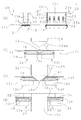
先ず、本発明の第1実施形態のバスダクトプラグインホール保護構造について、図1乃至図3を用いて説明する。尚、図1は、本発明の第1実施形態のバスダクトプラグインホール保護構造のバスダクトを示す図であり、(a)が平面図であり、(b)が側面図である。また、図2は、本発明の第1実施形態のバスダクトプラグインホール保護構造及びバスダクトの詳細を示す図であり、(a)がA−Aの模式断面図であり、(b)がB−Bの模式断面図であり、(c)がC−Cの模式断面図である。また、図3は、本発明の第1実施形態のバスダクトプラグインホール保護構造のプラグインホールにプラグイン装置を挿入する過程を示す模式図であり、(a)が挿入前の図、(b)が指示円S1部分の拡大図(挿入前)、(c)が指示円S1部分の拡大図(挿入中)、(d)が指示円S1部分の拡大図(挿入後)である。
<< First Embodiment >>
First, the bus duct plug-in hole protection structure according to the first embodiment of the present invention will be described with reference to FIGS. 1 to 3. 1A and 1B are views showing a bus duct having a bus duct plug-in hole protection structure according to the first embodiment of the present invention, wherein FIG. 1A is a plan view and FIG. 1B is a side view. Moreover, FIG. 2 is a figure which shows the detail of the bus duct plug-in-hole protection structure and bus duct of 1st Embodiment of this invention, (a) is a schematic cross section of AA, (b) is B- It is a schematic cross section of B, (c) is a schematic cross section of CC. FIG. 3 is a schematic view showing a process of inserting the plug-in device into the plug-in hole of the bus duct plug-in hole protection structure according to the first embodiment of the present invention. FIG. ) Is an enlarged view of the instruction circle S1 part (before insertion), (c) is an enlarged view of the instruction circle S1 part (during insertion), and (d) is an enlarged view of the instruction circle S1 part (after insertion).

第1実施形態のバスダクトプラグインホール保護構造1は、例えば空気層によって絶縁された空気絶縁型の複数(この場合、一例としてRST三相+中性相の四本)のバスダクト導体2をハウジング11内部に収容したバスダクト10と、バスダクト10の各バスダクト導体2それぞれに対応する複数(この場合、一例として四個)の接触子21を有するプラグイン装置20を具えている(図3参照)。そして、バスダクト10に設けられたプラグインホール12に対してプラグイン装置20の接触子21が挿入(プラグイン)されてバスダクト導体2と接続されることにより、電気幹線の主幹としてのバスダクト10に対してプラグイン装置20が電気的に接続されるようになっている。以下、第1実施形態のバスダクトプラグインホール保護構造1の詳細を説明していく。  The bus duct plug-in-hole protection structure 1 according to the first embodiment includes, for example, a plurality of air-insulated bus duct conductors 2 (in this case, four RST three-phase plus four neutral phases) that are insulated by an air layer. There is provided a plug-in device 20 having a bus duct 10 housed therein and a plurality of (in this case, four) contacts 21 corresponding to each bus duct conductor 2 of the bus duct 10 (see FIG. 3). The contact 21 of the plug-in device 20 is inserted (plugged in) into the plug-in hole 12 provided in the bus duct 10 and connected to the bus duct conductor 2, so that the bus duct 10 as the main trunk of the electric trunk line is connected. On the other hand, the plug-in device 20 is electrically connected. Hereinafter, the details of the bus duct plug-in hole protection structure 1 of the first embodiment will be described.

先ず、第1実施形態のバスダクトプラグインホール保護構造1を構成するバスダクト10について説明する。図1及び図2に示すように、バスダクト10は、空気層によって絶縁された空気絶縁型の四本のバスダクト導体2が、図示しない絶縁ホルダによって支持されてハウジング11の内部に配置されている。ハウジング11は、全体として断面視で中空の略直方体形状(すなわち略ロ字形状)であり、一対のハウジング半体を組み合わせて形成されている。尚、バスダクト10の絶縁は空気絶縁型だけに限らず、絶縁性のシートで覆うことで絶縁する絶縁被覆型のものでも良い。  First, the bus duct 10 constituting the bus duct plug-in hole protection structure 1 of the first embodiment will be described. As shown in FIGS. 1 and 2, the bus duct 10 includes four air-insulated bus duct conductors 2 insulated by an air layer, supported by an insulating holder (not shown) and disposed inside the housing 11. The housing 11 as a whole has a hollow, substantially rectangular parallelepiped shape (that is, a substantially rectangular shape) in a sectional view, and is formed by combining a pair of housing halves. The insulation of the bus duct 10 is not limited to the air insulation type, but may be an insulation coating type that is insulated by covering with an insulating sheet.

一対のハウジング半体は、断面視で下側に開放した略コ字形状の上側ハウジング半体11aと、断面視で上側に開放した略コ字形状の下側ハウジング半体11bとからなる。これら上側ハウジング半体11aおよび下側ハウジング半体11bには、その両側壁を、断面視で内方から外方に略凸形状に突出変形させることで形成された突出部としての補強部14がバスダクト10の長手方向に沿って設けられ、電気幹線を形成するバスダクト10全体の強度を向上するようになされている。  The pair of housing halves includes a substantially U-shaped upper housing half 11a opened downward in a sectional view and a substantially U-shaped lower housing half 11b opened upward in a sectional view. The upper housing half body 11a and the lower housing half body 11b have reinforcing portions 14 as projecting portions formed by projecting and deforming both side walls so as to project substantially inwardly from the inside in a sectional view. It is provided along the longitudinal direction of the bus duct 10 to improve the strength of the entire bus duct 10 forming the electric trunk line.

また、下側ハウジング半体11bは、その幅(側壁同士の間隔)が上側ハウジング半体11aの幅よりも僅かに狭く形成されている。これにより、下側ハウジング半体11bの開放端を上にして配置し、その上から上側ハウジング反対11aの開放端を覆い被せると、側壁の補強部14同士が嵌合することになり、側壁の嵌合部分をビス留め等して固定することでハウジング11が組み立てられるようになされている。そして、組み立て後のハウジング11における両側壁の補強部14の内側には、側壁を略凸形状に突出変形させることに伴い、略凹形状の突出空間としての補強空間15(上から順に15a・15b・15c)が形成される。  Further, the lower housing half 11b is formed such that its width (interval between the side walls) is slightly narrower than the width of the upper housing half 11a. As a result, when the open end of the lower housing half 11b is placed upward and the open end of the upper housing opposite 11a is covered from above, the side wall reinforcing portions 14 are fitted together, and the side wall The housing 11 is assembled by fixing the fitting portion with screws or the like. And the reinforcement space 15 (15a and 15b in order from the top) as a substantially concave-shaped protruding space is formed inside the reinforcing portion 14 on both side walls in the assembled housing 11 as the side walls protrude and deform into a substantially convex shape. 15c) is formed.

上側ハウジング半体11aは、図1に示すように、その上面にプラグインホール12が所定間隔で複数形成されており、上側ハウジング半体11aの内側に配置されたシャッタ部材13によって閉塞されている。尚、ここでは一例として、プラグインホール12を上側ハウジング半体11aに複数形成するようにした場合について述べるが、プラグインホール12が形成されるのは下側ハウジング半体11bでも良いし、上側ハウジング半体11aと下側ハウジング半体11bの両方でも良く、その数や配置も特に限定しない。  As shown in FIG. 1, a plurality of plug-in holes 12 are formed on the upper surface of the upper housing half 11a at a predetermined interval, and are closed by a shutter member 13 disposed inside the upper housing half 11a. . Here, as an example, a case where a plurality of plug-in holes 12 are formed in the upper housing half 11a will be described. However, the plug-in holes 12 may be formed in the lower housing half 11b or the upper housing half 11a. Both the housing half 11a and the lower housing half 11b may be used, and the number and arrangement thereof are not particularly limited.

プラグインホール12を閉塞する扉部材あるいは開閉部材としてのシャッタ部材13は、図2に示すように、プラグインホール12をバスダクト10の長手方向に二分して閉塞するかのようにしてお互いに対向して配置された一対の第1シャッタ部材13a及び第2シャッタ部材13bとからなり、これら第1シャッタ部材13a及び第2シャッタ部材13bのそれぞれに、両側壁の補強空間15a同士の間を架け渡せる長さの閉塞部13cが形成されている。また、この閉塞部13cの両端側には、補強空間15aの高さよりも僅かに低いスライド部13dが形成されている。すなわち、これら第1シャッタ部材13a及び第2シャッタ部材13bは、ハウジング11の両側壁の補強空間15a・15aに閉塞部13cが架け渡されると、補強空間15aの内部に位置決めされると共に、スライド部13dがスライド可能な状態で補強空間15a内に収納されるようになされている。これにより、第1シャッタ部材13a及び第2シャッタ部材13bは、プラグインホール12を両開き式にスライド開閉できるようになされている。  As shown in FIG. 2, the shutter member 13 serving as a door member or an opening / closing member that closes the plug-in hole 12 faces each other as if the plug-in hole 12 was divided in the longitudinal direction of the bus duct 10. A pair of first shutter member 13a and second shutter member 13b arranged in this manner, and each of the first shutter member 13a and second shutter member 13b can span between the reinforcing spaces 15a on both side walls. A length of the blocking portion 13c is formed. Further, slide portions 13d that are slightly lower than the height of the reinforcing space 15a are formed on both ends of the closing portion 13c. In other words, the first shutter member 13a and the second shutter member 13b are positioned inside the reinforcing space 15a and slidable when the closing portion 13c is bridged over the reinforcing spaces 15a and 15a on both side walls of the housing 11. 13d is slidably accommodated in the reinforcing space 15a. Thus, the first shutter member 13a and the second shutter member 13b can slide open and close the plug-in hole 12 in a double-open manner.

このように、第1実施形態のシャッタ部材13がスライド開閉式であるため、例えば作業者が不用意にシャッタ部材13に触れてしまうような場合に、プラグインホール12に直交する方向の力が加えられてもシャッタ部材13が開くことはなく、その分、プラグインホール12の保護が強固なものとなる。また、シャッタ部材13が第1シャッタ部材13a及び第2シャッタ部材13bからなる両開きのスライド開閉式であるため、一方のシャッタ部材が開く方向の力が加えられても他方のシャッタ部材が開くことはなく、つまりは、例えば作業者が不用意にシャッタ部材に触れてしまうような場合に、第1シャッタ部材13aと第2シャッタ部材13bの両方が一度に開いてしまう危険性を極力回避でき、その分、プラグインホール12の保護が強固なものとなる。  Thus, since the shutter member 13 of the first embodiment is a slide opening / closing type, for example, when an operator carelessly touches the shutter member 13, a force in a direction perpendicular to the plug-in hole 12 is generated. Even if added, the shutter member 13 does not open, and the protection of the plug-in hole 12 is strengthened accordingly. Further, since the shutter member 13 is a double-opening slide opening type composed of the first shutter member 13a and the second shutter member 13b, even if a force in the direction in which one shutter member opens is applied, the other shutter member does not open. In other words, for example, when an operator inadvertently touches the shutter member, the risk of both the first shutter member 13a and the second shutter member 13b opening at once can be avoided as much as possible. Therefore, the protection of the plug-in hole 12 becomes strong.

また、第1シャッタ部材13a及び第2シャッタ部材13bには、プラグインホール12の閉塞時に相互に接触する閉塞部13cの端辺の全域に亘って、プラグインホール12の外方から内方に向けて傾斜するシャッタ開放ガイド部13eが設けられている。このシャッタ開放ガイド部13eに対し、後述するプラグイン装置20のシャッタ開放部(扉開放部)が押し当てられることによって、プラグイン装置20を挿入する方向の動きが第1シャッタ部材13a及び第2シャッタ部材13bを開放方向にスライドさせる動きに変換されるようになされている。尚、シャッタ開放ガイド部13eは、プラグインホール12の閉塞時に相互に接触する閉塞部13cの端辺のうち、少なくとも後述するシャッタ開放部が接触する部分に形成されていれば良い。  Further, the first shutter member 13a and the second shutter member 13b are provided from the outer side to the inner side of the plug-in hole 12 over the entire end side of the closing part 13c that contacts each other when the plug-in hole 12 is closed. A shutter opening guide portion 13e that is inclined toward the surface is provided. When a shutter opening portion (door opening portion) of the plug-in device 20 described later is pressed against the shutter opening guide portion 13e, the movement in the direction in which the plug-in device 20 is inserted changes the first shutter member 13a and the second shutter member 13a. The shutter member 13b is converted into a movement that slides in the opening direction. The shutter opening guide portion 13e may be formed in at least a portion where the shutter opening portion to be described later contacts among the end sides of the closing portion 13c that contact each other when the plug-in hole 12 is closed.

さらに、これら第1シャッタ部材13a及び第2シャッタ部材13bは、螺旋(コイル)状のバネ部材16によって相互に連結されている。具体的には、第1シャッタ部材13aのスライド部13dの近傍で閉塞部13cにおける第2シャッタ部材13bの反対側の位置にバネ係止部13fが設けられており、また、第2シャッタ部材13bの両側のスライド部13dの近傍で閉塞部13cにおける第1シャッタ部材13aの反対側の位置に、バネ係止部13fが設けられている。そして、第1シャッタ部材13aのバネ係止部13fと第2シャッタ部材13bのバネ係止部13fとを連結するようにして、バネ部材16が係止されている。  Further, the first shutter member 13 a and the second shutter member 13 b are connected to each other by a spiral (coil) spring member 16. Specifically, a spring engaging portion 13f is provided in the vicinity of the slide portion 13d of the first shutter member 13a at a position opposite to the second shutter member 13b in the closing portion 13c, and the second shutter member 13b. A spring locking portion 13f is provided at a position on the opposite side of the first shutter member 13a in the closing portion 13c in the vicinity of the slide portions 13d on both sides. The spring member 16 is locked so as to connect the spring locking portion 13f of the first shutter member 13a and the spring locking portion 13f of the second shutter member 13b.

これにより、第1シャッタ部材13a及び第2シャッタ部材13bは、バネ部材16によって相互に引き付けられるため、相互に近づく方向、すなわちプラグインホール12を閉塞する方向にお互いが付勢されるようになっている。このとき、一つのバネ部材16で第1シャッタ部材13aと第2シャッタ部材13bの両方を付勢しているため、それぞれにバネ部材を別個に設ける場合よりもバネ部材の数が半分になり、その分だけ構造が簡単で部品数も少なくコストがかからなくて済む。  Thereby, since the first shutter member 13a and the second shutter member 13b are attracted to each other by the spring member 16, the first shutter member 13a and the second shutter member 13b are biased toward each other, that is, in a direction to close the plug-in hole 12. ing. At this time, since both the first shutter member 13a and the second shutter member 13b are urged by one spring member 16, the number of spring members is halved as compared with the case where the spring members are separately provided, Therefore, the structure is simple, the number of parts is small, and cost is not required.

また、第1シャッタ部材13aの一方の端と第2シャッタ部材13bの一方の端がバネ部材16によって連結されると共に、第1シャッタ部材13aの他方の端と第2シャッタ部材13bの他方の端がバネ部材16によって連結されるため、これら第1シャッタ部材13a及び第2シャッタ部材13bと二本のバネ部材16とがユニット化された状態となる(図2(b))。すなわち、ハウジング11の組み立て時において、このユニット化された第1シャッタ部材13a及び第2シャッタ部材13bと二本のバネ部材16を取り付けるだけで済むことになるため、個々の部材を別個に取り付ける場合に比べて組み立て作業が容易になるという利点がある。  One end of the first shutter member 13a and one end of the second shutter member 13b are connected by a spring member 16, and the other end of the first shutter member 13a and the other end of the second shutter member 13b. Are connected by the spring member 16, the first shutter member 13 a and the second shutter member 13 b and the two spring members 16 are unitized (FIG. 2B). That is, when the housing 11 is assembled, it is only necessary to attach the unitized first shutter member 13a and second shutter member 13b and the two spring members 16, so that individual members are attached separately. There is an advantage that the assembling work becomes easier compared to.

ここで、補強空間15aには、上側ハウジング半体11aの外側から上板を貫通するようにして、ボルトやビスを締結したりリベット等を打ち込むことにより、第1シャッタ部材13a及び第2シャッタ部材13bの移動を規制する規制部17が設けられている。この規制部17は、例えば、プラグインホール12のバスダクト10の長手方向における略中央に設けられることにより、第1シャッタ部材13aが規制部17を越えて第2シャッタ部材13b側へ移動することを規制すると共に、第2シャッタ部材13bが規制部17を越えて第1シャッタ部材13a側へ移動することを規制するようになされている。尚、この規制部17は、第1シャッタ部材13a用と第2シャッタ部材13b用とに別に設けても良い。  Here, the first shutter member 13a and the second shutter member are inserted into the reinforcing space 15a by fastening bolts or screws or driving rivets or the like so as to penetrate the upper plate from the outside of the upper housing half 11a. A restricting portion 17 for restricting the movement of 13b is provided. For example, the restricting portion 17 is provided at substantially the center of the plug-in hole 12 in the longitudinal direction of the bus duct 10, so that the first shutter member 13 a moves beyond the restricting portion 17 to the second shutter member 13 b side. In addition to the restriction, the movement of the second shutter member 13b beyond the restriction portion 17 to the first shutter member 13a side is restricted. The restricting portion 17 may be provided separately for the first shutter member 13a and the second shutter member 13b.

これにより、第1実施形態のバスダクトプラグインホール保護構造1のようにバネ部材16がバスダクト10のハウジング11に固定されていない状態においても、第1シャッタ部材13a及び第2シャッタ部材13bが所定位置を越えて移動してしまうような事態、すなわち第1シャッタ部材13a及び第2シャッタ部材13bがずれてプラグインホール12が不用意に開放されてしまうような事態を、規制部17を補強空間15aに設けるという簡易な構造だけで容易に回避できる。  Thus, even when the spring member 16 is not fixed to the housing 11 of the bus duct 10 as in the bus duct plug-in hole protection structure 1 of the first embodiment, the first shutter member 13a and the second shutter member 13b are in a predetermined position. If the first shutter member 13a and the second shutter member 13b are displaced and the plug-in hole 12 is inadvertently opened, the restricting portion 17 is provided in the reinforcing space 15a. This can be easily avoided with only a simple structure.

このように、第1実施形態のバスダクトプラグインホール保護構造1のバスダクト10は形成されており、プラグインホール2を閉塞するシャッタ部材13(第1シャッタ部材13a及び第2シャッタ部材13b)と、シャッタ部材13を閉塞方向に付勢するバネ部材16とを別部材によって形成しているため、シャッタ部材13の強度とバネ部材16の強度とを別個に設定することができる。すなわち、本発明によれば、プラグイン装置20のプラグイン時の施工性を悪化させることなく強固な保護構造を提供することができるため、作業者の感電等を防ぐための強固な保護とプラグイン時の施工性とを両立可能な保護構造を提供することができる。  Thus, the bus duct 10 of the bus duct plug-in hole protection structure 1 of the first embodiment is formed, and the shutter member 13 (the first shutter member 13a and the second shutter member 13b) that closes the plug-in hole 2, and Since the spring member 16 that biases the shutter member 13 in the closing direction is formed by a separate member, the strength of the shutter member 13 and the strength of the spring member 16 can be set separately. That is, according to the present invention, since a strong protective structure can be provided without deteriorating the workability at the time of plug-in of the plug-in device 20, it is possible to provide a strong protection and plug for preventing an electric shock of an operator. It is possible to provide a protective structure capable of achieving both workability during in-run.

また、第1実施形態のバスダクトプラグインホール保護構造1のバスダクト10において、断面視略ロ字形状のハウジング11には、断面視で内方から外方に略凸形状に突出する突出部としての補強部14が形成されており、シャッタ部材13を構成する部材の一部とバネ部材16と規制部17とが(すなわち、プラグインホールを閉塞することに関わる部材の一部が)、補強部14の内側の略凹形状の突出空間としての補強空間15aに配置されている。このため、バスダクト10の内部に収納されているバスダクト導体2とハウジング11との間の空間絶縁距離や沿面距離等を極力阻害することなく、シャッタ部材13の一部やバネ部材16といったプラグインホールを閉塞することに関わる部材の一部をハウジング11の内部に収納することができる。すなわち、シャッタ部材13等のプラグインホールを閉塞することに関わる部材を設けることに起因して空間絶縁距離や沿面距離等を確保するためにバスダクト10が巨大化してしまうような事態を極力回避し得る。  Further, in the bus duct 10 of the bus duct plug-in-hole protection structure 1 according to the first embodiment, the housing 11 having a substantially rectangular shape in cross section has a protruding portion that protrudes in a substantially convex shape from the inside to the outside in the cross sectional view. The reinforcing part 14 is formed, and a part of the member constituting the shutter member 13, the spring member 16, and the restricting part 17 (that is, a part of the member related to closing the plug-in hole) are included in the reinforcing part. 14 is disposed in a reinforcing space 15a as a substantially concave protruding space inside. For this reason, a plug-in hole such as a part of the shutter member 13 and the spring member 16 is provided without hindering the space insulation distance, creepage distance, and the like between the bus duct conductor 2 housed inside the bus duct 10 and the housing 11 as much as possible. A part of the member involved in closing the housing can be accommodated in the housing 11. That is, the situation where the bus duct 10 becomes enormous in order to secure a space insulation distance, a creepage distance, and the like due to providing a member related to closing the plug-in hole such as the shutter member 13 is avoided as much as possible. obtain.

次に、第1実施形態のバスダクトプラグインホール保護構造1を構成するプラグイン装置20について説明する。プラグイン装置20は、図3に示すように、遮断器等(図示せず)を内部に収納した箱形状の本体部22と、バスダクト10の各バスダクト導体2それぞれに対応して本体部22から突設された複数(この場合、一例として四個)のクリップ状の接触子21と、この接触子21を支持すると共に保護するための絶縁樹脂製の絶縁ホルダ23と、シャッタ部材13を開放するためのシャッタ開放部24とを有している。  Next, the plug-in device 20 constituting the bus duct plug-in hole protection structure 1 of the first embodiment will be described. As shown in FIG. 3, the plug-in device 20 includes a box-shaped main body 22 in which a circuit breaker or the like (not shown) is housed, and a main body 22 corresponding to each bus duct conductor 2 of the bus duct 10. A plurality of (in this case, for example, four) clip-like contacts 21 that are provided in a protruding manner, an insulating holder 23 made of an insulating resin for supporting and protecting the contacts 21, and the shutter member 13 are opened. And a shutter opening 24 for the purpose.

ここで、絶縁ホルダ23は、プラグイン時にバスダクト導体2を受け入れる溝23aがバスダクト10のバスダクト導体2の位置に合わせて複数個並べて形成され、この溝23aに接触子21が配置されるようになされている。また、絶縁ホルダ23は、全体として略直方体形状をしており、底面視においてプラグインホール12よりも僅かに小さい略相似形状に形成されている。  Here, in the insulating holder 23, a plurality of grooves 23a for receiving the bus duct conductor 2 at the time of plug-in are formed side by side in accordance with the position of the bus duct conductor 2 of the bus duct 10, and the contact 21 is arranged in the groove 23a. ing. The insulating holder 23 has a substantially rectangular parallelepiped shape as a whole, and is formed in a substantially similar shape slightly smaller than the plug-in hole 12 in a bottom view.

シャッタ開放部24は、絶縁ホルダ23の両側の側壁23bに沿って設けられ、側壁23bと同じ幅、あるいは側壁23bよりも幅広に形成されている。これにより、プラグイン挿入時、シャッタ開放部24によって第1シャッタ部材13a及び第2シャッタ部材13bを開放する際、絶縁ホルダ23に第1シャッタ部材13a及び第2シャッタ部材13bが引っかかることなく挿入することができる。尚、シャッタ開放部24を主として、各部材を導電性の部材で形成することで、このシャッタ開放部24を介してバスダクト10とプラグイン装置20とをアース接続することも可能である。また、シャッタ開放部24には、絶縁ホルダ23よりも下方に突出する左右対称で略二等辺三角形状の開放片24aが形成されている。この開放片24aは、絶縁ホルダ23側に僅かに屈曲形成されている。これにより、プラグイン挿入時、シャッタ開放部24の開放片24aがプラグインホール12に挿入し易くなる。  The shutter opening portion 24 is provided along the side wall 23b on both sides of the insulating holder 23, and is formed to have the same width as the side wall 23b or wider than the side wall 23b. Accordingly, when the plug-in is inserted, when the first shutter member 13a and the second shutter member 13b are opened by the shutter opening portion 24, the first shutter member 13a and the second shutter member 13b are inserted into the insulating holder 23 without being caught. be able to. Note that the bus duct 10 and the plug-in device 20 can be grounded via the shutter opening portion 24 by forming the shutter opening portion 24 as a main component and using conductive members. Further, the shutter opening portion 24 is formed with a bilaterally symmetrical isosceles triangle-shaped opening piece 24 a that protrudes downward from the insulating holder 23. The open piece 24a is slightly bent toward the insulating holder 23 side. This facilitates insertion of the opening piece 24a of the shutter opening portion 24 into the plug-in hole 12 when the plug-in is inserted.

このように、第1実施形態のバスダクトプラグインホール保護構造1のプラグイン装置20は形成されており、シャッタ開放部24が設けられている点に特徴がある。  Thus, the plug-in device 20 of the bus duct plug-in hole protection structure 1 according to the first embodiment is formed and is characterized in that the shutter opening portion 24 is provided.

以下、第1実施形態のバスダクトプラグインホール保護構造1において、プラグインホール12に対してプラグイン装置20を挿入する際の動作について図3を用いて説明する。  Hereinafter, the operation when the plug-in device 20 is inserted into the plug-in hole 12 in the bus duct plug-in hole protection structure 1 of the first embodiment will be described with reference to FIG.

図3(a)及び(b)は、バスダクト10のプラグインホール12に対してプラグイン装置20を挿入する前の状態を示す図であり、シャッタ開放部24の略二等辺三角形状の開放片24aの先端が、第1シャッタ部材13aのシャッタ開放ガイド部13eと第2シャッタ部材13bのシャッタ開放ガイド部13eとが接する部分の略直上に位置するようにプラグイン装置20が配置されている。  FIGS. 3A and 3B are views showing a state before the plug-in device 20 is inserted into the plug-in hole 12 of the bus duct 10, and an opening piece having a substantially isosceles triangular shape of the shutter opening portion 24. The plug-in device 20 is disposed so that the tip of 24a is positioned substantially immediately above the portion where the shutter opening guide portion 13e of the first shutter member 13a and the shutter opening guide portion 13e of the second shutter member 13b are in contact.

図3(c)は、プラグインホール12に対してプラグイン装置20を近づけて挿入する動作が開始された状態を示す図であり、シャッタ開放部24の略二等辺三角形状の開放片24aの先端が第1シャッタ部材13aのシャッタ開放ガイド部13eと第2シャッタ部材13bのシャッタ開放ガイド部13eとに接触し、第1シャッタ部材13a及び第2シャッタ部材13bを相互に離間する方向にスライドさせている。すなわち、シャッタ開放ガイド部13eに対してシャッタ開放部24の略三角形状の開放片24aが押し当てられることによって、プラグイン装置20を近づけて挿入する方向の動作が第1シャッタ部材13a及び第2シャッタ部材13bを開放方向にスライドさせる動作に変換されており、その力がバネ部材16の付勢力を越えたときに、プラグインホール12が開放されていくようになされている。  FIG. 3C is a diagram showing a state in which the operation of inserting the plug-in device 20 closer to the plug-in hole 12 is started, and the opening piece 24a of the substantially isosceles triangular shape of the shutter opening portion 24 is shown. The tip is in contact with the shutter opening guide portion 13e of the first shutter member 13a and the shutter opening guide portion 13e of the second shutter member 13b, and the first shutter member 13a and the second shutter member 13b are slid in a direction away from each other. ing. In other words, when the substantially triangular opening piece 24a of the shutter opening portion 24 is pressed against the shutter opening guide portion 13e, the operation in the direction in which the plug-in device 20 is inserted closer is the first shutter member 13a and the second shutter member 13a. The operation is converted into an operation of sliding the shutter member 13b in the opening direction, and the plug-in hole 12 is opened when the force exceeds the urging force of the spring member 16.

図3(d)は、プラグインホール12に対してプラグイン装置20を挿入する動作が完了した状態を示す図であり、シャッタ開放部24の略二等辺三角形状の開放片24aによって第1シャッタ部材13aと第2シャッタ部材13bとが開放され、絶縁ホルダ23とこの絶縁ホルダ23に保護された接触子21とがプラグインホール12の内部に挿入されている。その結果、クリップ状の各接触子21が対応するバスダクト導体2を挟持することになり、バスダクト10とプラグイン装置20との電気的接続が達成される。  FIG. 3D is a diagram illustrating a state in which the operation of inserting the plug-in device 20 into the plug-in hole 12 is completed. The first shutter is opened by the substantially isosceles triangular opening piece 24 a of the shutter opening portion 24. The member 13 a and the second shutter member 13 b are opened, and the insulating holder 23 and the contact 21 protected by the insulating holder 23 are inserted into the plug-in hole 12. As a result, each clip-shaped contact 21 sandwiches the corresponding bus duct conductor 2, and electrical connection between the bus duct 10 and the plug-in device 20 is achieved.

尚、絶縁ホルダ23の正面側の略中央には誤挿入防止リブ23cが形成されている(図3(a)参照)。また、プラグインホール12の縁には、プラグイン時にこの誤挿入防止リブ23cを通過させるための誤挿入防止切欠12aが形成されている(図1(a)及び図2(b)参照)。これにより、バスダクトプラグインホール保護構造1では、プラグイン時において、プラグインホール12の誤挿入防止切欠12aを通過する方向以外のプラグイン装置20の挿入が絶縁ホルダ23の誤挿入防止リブ23cにより防止される。  In addition, an erroneous insertion preventing rib 23c is formed in the approximate center of the front side of the insulating holder 23 (see FIG. 3A). Further, an incorrect insertion prevention notch 12a is formed at the edge of the plug-in hole 12 for allowing the erroneous insertion prevention rib 23c to pass during plug-in (see FIGS. 1A and 2B). Thereby, in the bus duct plug-in hole protection structure 1, the plug-in device 20 is inserted by the erroneous insertion prevention rib 23 c of the insulating holder 23 in the direction other than passing through the erroneous insertion prevention notch 12 a of the plug-in hole 12 at the time of plug-in. Is prevented.

このように、第1実施形態のバスダクトプラグインホール保護構造1は、バスダクト10のプラグインホール12に対してプラグイン装置20を挿入する(近づける)動作により、図3(b)→(c)→(d)のように、第1シャッタ部材13a及び第2シャッタ部材13bが自動で開放されるようになされている。  As described above, the bus duct plug-in hole protection structure 1 according to the first embodiment performs the operation of inserting (approaching) the plug-in device 20 into the plug-in hole 12 of the bus duct 10 as shown in FIG. → As shown in (d), the first shutter member 13a and the second shutter member 13b are automatically opened.

また、第1実施形態のバスダクトプラグインホール保護構造1において、プラグインホール12からプラグイン装置20を引き抜く際のシャッタ部材13の動作については、第1シャッタ部材13a及び第2シャッタ部材13bがバネ部材16によってプラグインホール12の閉塞方向に常に付勢されているため、単純に挿入時とは逆の動作となり、図3(d)→(c)→(b)のように、第1シャッタ部材13a及び第2シャッタ部材13bが自動で閉塞されるようになされている。  In the bus duct plug-in hole protection structure 1 according to the first embodiment, the first shutter member 13a and the second shutter member 13b are springs for the operation of the shutter member 13 when the plug-in device 20 is pulled out from the plug-in hole 12. Since the member 16 is always urged in the closing direction of the plug-in hole 12, the operation is simply the reverse of the insertion, and the first shutter as shown in FIG. 3 (d) → (c) → (b). The member 13a and the second shutter member 13b are automatically closed.

以上説明したように、第1実施形態のバスダクトプラグインホール保護構造1は、プラグイン装置20の未接続時にはシャッタ部材13でプラグインホール12を閉塞し、バスダクト10のプラグインホール12に対するプラグイン装置20の着脱の際にはその動作に応じてシャッタ部材13が自動で開閉されるようになされており、作業者の感電等を防ぐための強固な保護とプラグイン時の施工性との両方を提供できる。  As described above, the bus duct plug-in hole protection structure 1 of the first embodiment closes the plug-in hole 12 with the shutter member 13 when the plug-in device 20 is not connected, and plugs in the plug-in hole 12 of the bus duct 10. When the apparatus 20 is attached / detached, the shutter member 13 is automatically opened and closed according to the operation thereof, and both strong protection for preventing an electric shock of the operator and workability at the time of plug-in are provided. Can provide.

《第2実施形態》
次に、本発明の第2実施形態のバスダクトプラグインホール保護構造100について、図4及び図5を用いて説明する。尚、図4は、本発明の第2実施形態のバスダクトプラグインホール保護構造及びバスダクトの詳細を示す図であり、(a)が模式断面図であり、(b)がD−Dの模式断面図であり、(c)がE−Eの模式断面図である。また、図5は、本発明の第2実施形態のバスダクトプラグインホール保護構造のプラグインホールにプラグイン装置を挿入する過程を示す模式図であり、(a)が挿入前の拡大図、(b)が挿入中の拡大図、(c)が挿入後の拡大図である。
<< Second Embodiment >>
Next, a bus duct plug-in hole protection structure 100 according to a second embodiment of the present invention will be described with reference to FIGS. 4A and 4B are diagrams showing details of the bus duct plug-in hole protection structure and the bus duct according to the second embodiment of the present invention, wherein FIG. 4A is a schematic cross-sectional view, and FIG. 4B is a schematic cross-section taken along DD. It is a figure and (c) is a schematic cross section of EE. FIG. 5 is a schematic diagram showing a process of inserting the plug-in device into the plug-in hole of the bus duct plug-in hole protection structure according to the second embodiment of the present invention, and (a) is an enlarged view before insertion. b) is an enlarged view during insertion, and (c) is an enlarged view after insertion.

尚、第2実施形態のバスダクトプラグインホール保護構造100は、シャッタ部材及びバネ部材の構造が、第1実施形態のバスダクトプラグインホール保護構造1とは異なる。よって、この第2実施形態では、説明の便宜上、第1実施形態と同様の構成又は相当する部分となるものには同じ符号を付すと共に、第1実施形態と異なる部分(すなわちシャッタ部材及びバネ部材の構造)を詳細に説明し、同様の構成の部分については説明を省略する。  The bus duct plug-in hole protection structure 100 of the second embodiment differs from the bus duct plug-in hole protection structure 1 of the first embodiment in the structure of the shutter member and the spring member. Therefore, in this second embodiment, for convenience of explanation, the same reference numerals are given to components that are the same as or correspond to those in the first embodiment, and different parts from the first embodiment (that is, shutter members and spring members). The structure of the same structure) will be described in detail, and the description of the same configuration will be omitted.

第2実施形態のシャッタ部材13は、図4に示すように、第1実施形態と同様にプラグインホール12を両開き式にスライド開閉可能な一対の第1シャッタ部材13a及び第2シャッタ部材13bとからなり、螺旋(コイル)状のバネ部材116と例えばボルトおよびナットからなる連結部材18とによって相互に連結されている。  As shown in FIG. 4, the shutter member 13 of the second embodiment includes a pair of first shutter member 13 a and second shutter member 13 b that can slide open and close the plug-in hole 12 in a double-open manner, as in the first embodiment. And are connected to each other by a spiral (coil) spring member 116 and a connecting member 18 made of, for example, a bolt and a nut.

具体的には、第1シャッタ部材13aのスライド部13dにおける第2シャッタ部材13b側の位置に、スライド部13dを内側に屈曲延設するようにしてバネ止部113fが設けられており、また、第2シャッタ部材13bのスライド部13dにおける第1シャッタ部材13a側の位置に、スライド部13dを内側に屈曲延設するようにしてバネ止部113fが設けられている。また、第1シャッタ部材13a及び第2シャッタ部材13bそれぞれのバネ止部113fには、連結部材18を挿通可能であると共にバネ部材116を挿通不可能な大きさの挿通孔113gが設けられている。  Specifically, a spring stopper 113f is provided at a position on the second shutter member 13b side of the slide portion 13d of the first shutter member 13a so as to bend and extend the slide portion 13d inward. A spring stopper 113f is provided at a position on the first shutter member 13a side of the slide portion 13d of the second shutter member 13b so as to bend and extend the slide portion 13d inward. The spring stoppers 113f of the first shutter member 13a and the second shutter member 13b are each provided with an insertion hole 113g that can be inserted through the connecting member 18 and cannot be inserted through the spring member 116. .

そして、第1シャッタ部材13aの挿通孔113gと第2シャッタ部材13bの挿通孔113gとを連結するように連結部材18が挿通され、第1シャッタ部材13aのバネ止部113fと連結部材18の一方の端部18aとの間に一本目のバネ部材116が収まるように、この螺旋状のバネ部材116に連結部材18が挿通されており、同様に、第2シャッタ部材13bのバネ止部113fと連結部材18の他方の端部18bとの間に二本目のバネ部材116が収まるように、この螺旋状のバネ部材116に連結部材18が挿通されている。  Then, the connecting member 18 is inserted so as to connect the insertion hole 113g of the first shutter member 13a and the insertion hole 113g of the second shutter member 13b, and one of the spring stopper 113f of the first shutter member 13a and one of the connecting members 18 is connected. The connecting member 18 is inserted into the spiral spring member 116 so that the first spring member 116 is accommodated between the end 18a of the second shutter member 13b and the spring stopper 113f of the second shutter member 13b. The connecting member 18 is inserted into the spiral spring member 116 so that the second spring member 116 is accommodated between the other end 18 b of the connecting member 18.

その結果、第1シャッタ部材13a側のバネ部材116は、その一端側で連結部材18の一方の端部18aを押圧すると共に他端側でバネ止部113fを押圧するようになされている。同様に、第2シャッタ部材13a側のバネ部材116は、その他端側で連結部材18の他方の端部18bを押圧すると共に一端側でバネ止部113fを押圧するようになされている。  As a result, the spring member 116 on the first shutter member 13a side is configured to press one end portion 18a of the connecting member 18 at one end side and press the spring stopper 113f on the other end side. Similarly, the spring member 116 on the second shutter member 13a side presses the other end portion 18b of the connecting member 18 on the other end side and presses the spring stopper 113f on one end side.

このようにして、第2実施形態のバスダクトプラグインホール保護構造100において、第1シャッタ部材13a及び第2シャッタ部材13bは、バネ部材116によって相互に近づく方向、すなわちプラグインホール12を閉塞する方向にお互いが付勢されるようになっている。その結果、この第2実施形態のバスダクトプラグインホール保護構造100においても、上述した第1実施形態のバスダクトプラグインホール保護構造1と同様の効果を得ることができる。  Thus, in the bus duct plug-in hole protection structure 100 according to the second embodiment, the first shutter member 13a and the second shutter member 13b approach each other by the spring member 116, that is, the direction in which the plug-in hole 12 is closed. Each other is energized. As a result, also in the bus duct plug-in hole protection structure 100 of the second embodiment, the same effect as the bus duct plug-in hole protection structure 1 of the first embodiment described above can be obtained.

一方で、第2実施形態のバスダクトプラグインホール保護構造100において、バネ部材116が第1シャッタ部材13a及び第2シャッタ部材13bのそれぞれに別個に設けられ、螺旋状のバネ部材116の中に連結部材18が挿通されている点が、第1実施形態のバスダクトプラグインホール保護構造1の第1シャッタ部材13a及び第2シャッタ部材13bとは異なる。  On the other hand, in the bus duct plug-in hole protection structure 100 according to the second embodiment, the spring member 116 is provided separately for each of the first shutter member 13a and the second shutter member 13b and is connected to the spiral spring member 116. The point where the member 18 is inserted is different from the first shutter member 13a and the second shutter member 13b of the bus duct plug-in hole protection structure 1 of the first embodiment.

これにより、仮に、何らかの原因によってバネ部材116が断線した場合であっても、バネ部材116が連結部材18に挿通されているため、断線したバネ部材116が垂下して、バスダクト導体2とハウジング11との間の空間絶縁距離や沿面距離等を阻害したり、バスダクト導体2と短絡してしまったりといった事態が発生することを回避できるようになされている。  As a result, even if the spring member 116 is disconnected due to some cause, the spring member 116 is inserted into the connecting member 18, so that the disconnected spring member 116 hangs down, and the bus duct conductor 2 and the housing 11. It is possible to avoid the occurrence of situations such as obstructing the space insulation distance and creepage distance between the two and the short circuit with the bus duct conductor 2.

また、第2実施形態のバスダクトプラグインホール保護構造100においても、シャッタ部材13を構成する部材の一部とバネ部材116と規制部17と連結部材18、すなわちプラグインホール12を閉塞することに関わる部材の一部が、補強部14の内側の略凹形状の補強空間15(この場合、特に補強部15a)に配置されている。このため、バスダクト10の内部に収納されているバスダクト導体2とハウジング11との間の空間絶縁距離や沿面距離等を極力阻害することなく、プラグインホール12を閉塞することに関わる部材の一部をハウジング11の内に収納することができる。すなわち、第2実施形態のバスダクトプラグインホール保護構造100においても、第1実施形態と同様に、シャッタ部材13を設けることに起因して空間絶縁距離や沿面距離等を確保するためにバスダクト10が巨大化してしまうような事態を極力回避し得る。  In the bus duct plug-in hole protection structure 100 according to the second embodiment, part of the members constituting the shutter member 13, the spring member 116, the restricting portion 17, and the connecting member 18, that is, the plug-in hole 12 is closed. A part of the member concerned is arrange | positioned in the substantially concave reinforcement space 15 (in this case, especially reinforcement part 15a) inside the reinforcement part 14. FIG. For this reason, some of the members involved in closing the plug-in hole 12 without hindering the space insulation distance, creepage distance, etc. between the bus duct conductor 2 and the housing 11 housed inside the bus duct 10 as much as possible. Can be stored in the housing 11. That is, also in the bus duct plug-in hole protection structure 100 of the second embodiment, the bus duct 10 is provided in order to ensure a space insulation distance, a creepage distance, and the like due to the provision of the shutter member 13 as in the first embodiment. It is possible to avoid the situation that becomes huge as much as possible.

以下、第2実施形態のバスダクトプラグインホール保護構造100において、プラグインホール12に対してプラグイン装置20を近づけて挿入する際のシャッタ部材13の動作について図5を用いて説明する。  Hereinafter, the operation of the shutter member 13 when the plug-in device 20 is inserted close to the plug-in hole 12 in the bus duct plug-in hole protection structure 100 of the second embodiment will be described with reference to FIG.

図5(a)は、バスダクト10のプラグインホール12に対してプラグイン装置20の接触子21を近づけて挿入する直前の状態を示す図であり、シャッタ開放部24の略二等辺三角形状の開放片24aの先端が、第1シャッタ部材13aのシャッタ開放ガイド部13eと第2シャッタ部材13bのシャッタ開放ガイド部13eとが接する部分の略直上に位置するようにプラグイン装置20が配置されている。  FIG. 5A is a diagram showing a state immediately before the contact 21 of the plug-in device 20 is inserted close to the plug-in hole 12 of the bus duct 10. The shutter opening 24 has a substantially isosceles triangular shape. The plug-in device 20 is arranged so that the tip of the opening piece 24a is positioned almost directly above the portion where the shutter opening guide portion 13e of the first shutter member 13a and the shutter opening guide portion 13e of the second shutter member 13b are in contact. Yes.

図5(b)は、プラグインホール12に対してプラグイン装置20を近づけて挿入する動作が開始された状態を示す図であり、シャッタ開放部24の略二等辺三角形状の開放片24aの先端が第1シャッタ部材13aのシャッタ開放ガイド部13eと第2シャッタ部材13bのシャッタ開放ガイド部13eとに接触し、第1シャッタ部材13a及び第2シャッタ部材13bが相互に離間する方向にスライドさせている。すなわち、シャッタ開放ガイド部13eに対してシャッタ開放部24の略三角形状の開放片24aが押し当てられることによって、プラグイン装置20を挿入する方向の動作が第1シャッタ部材13a及び第2シャッタ部材13bを開放方向にスライドさせる動作に変換されており、その力がバネ部材116の付勢力を越えたときに、プラグインホール12が開放されていくようになされている。  FIG. 5B is a diagram illustrating a state in which the operation of inserting the plug-in device 20 closer to the plug-in hole 12 is started, and the opening piece 24a having a substantially isosceles triangular shape of the shutter opening portion 24 is illustrated. The tip is in contact with the shutter opening guide portion 13e of the first shutter member 13a and the shutter opening guide portion 13e of the second shutter member 13b, and the first shutter member 13a and the second shutter member 13b are slid in a direction away from each other. ing. That is, when the substantially triangular opening piece 24a of the shutter opening portion 24 is pressed against the shutter opening guide portion 13e, the operation in the direction in which the plug-in device 20 is inserted is the first shutter member 13a and the second shutter member. It is converted into an operation of sliding 13b in the opening direction, and when the force exceeds the urging force of the spring member 116, the plug-in hole 12 is opened.

図5(c)は、プラグインホール12に対してプラグイン装置20を挿入する動作が完了した状態を示す図であり、シャッタ開放部24の略二等辺三角形状の開放片24aによって第1シャッタ部材13aと第2シャッタ部材13bとが開放され、絶縁ホルダ23とこの絶縁ホルダ23に保護された接触子21とがプラグインホール12の内部に挿入されている。その結果、クリップ状の各接触子21が対応するバスダクト導体2を挟持することになり、バスダクト10とプラグイン装置20との電気的接続が達成される。  FIG. 5C is a diagram illustrating a state in which the operation of inserting the plug-in device 20 into the plug-in hole 12 is completed. The first shutter is opened by the substantially isosceles triangular opening piece 24 a of the shutter opening portion 24. The member 13 a and the second shutter member 13 b are opened, and the insulating holder 23 and the contact 21 protected by the insulating holder 23 are inserted into the plug-in hole 12. As a result, each clip-shaped contact 21 sandwiches the corresponding bus duct conductor 2, and electrical connection between the bus duct 10 and the plug-in device 20 is achieved.

このように、第2実施形態のバスダクトプラグインホール保護構造100も、第1実施形態のバスダクトプラグインホール保護構造1と同様に、バスダクト10のプラグインホール12に対するプラグイン装置20の挿入動作により、図5(a)→(b)→(c)のように、第1シャッタ部材13a及び第2シャッタ部材13bが自動で開放されるようになされている。  As described above, the bus duct plug-in hole protection structure 100 of the second embodiment is also provided by the insertion operation of the plug-in device 20 into the plug-in hole 12 of the bus duct 10, similarly to the bus duct plug-in hole protection structure 1 of the first embodiment. As shown in FIGS. 5 (a) → (b) → (c), the first shutter member 13a and the second shutter member 13b are automatically opened.

また、第2実施形態のバスダクトプラグインホール保護構造100において、プラグインホール12からプラグイン装置20を引き抜く際のシャッタ部材13の動作についても、第1実施形態のバスダクトプラグインホール保護構造1と同様に、第1シャッタ部材13a及び第2シャッタ部材13bがバネ部材116によってプラグインホール12の閉塞方向に常に付勢されているため、単純に挿入時とは逆の動作となり、図5(c)→(b)→(a)のように、第1シャッタ部材13a及び第2シャッタ部材13bが自動で閉塞されるようになされている。  Further, in the bus duct plug-in hole protection structure 100 of the second embodiment, the operation of the shutter member 13 when the plug-in device 20 is pulled out from the plug-in hole 12 is the same as that of the bus duct plug-in hole protection structure 1 of the first embodiment. Similarly, since the first shutter member 13a and the second shutter member 13b are always urged in the closing direction of the plug-in hole 12 by the spring member 116, the operation is simply the reverse of the insertion, and FIG. ) → (b) → (a), the first shutter member 13a and the second shutter member 13b are automatically closed.

以上説明したように、第2実施形態のバスダクトプラグインホール保護構造100も、プラグイン装置20の未接続時にはシャッタ部材13でプラグインホール12を閉塞し、バスダクト10のプラグインホール12に対するプラグイン装置20の着脱の際にはその動作に応じてシャッタ部材13が自動で開閉されるようになされており、作業者の感電等を防ぐための強固な保護とプラグイン時の施工性との両方を提供できる。  As described above, the bus duct plug-in hole protection structure 100 of the second embodiment also closes the plug-in hole 12 with the shutter member 13 when the plug-in device 20 is not connected, and plugs in the plug-in hole 12 of the bus duct 10. When the apparatus 20 is attached / detached, the shutter member 13 is automatically opened and closed according to the operation thereof, and both strong protection for preventing an electric shock of the operator and workability at the time of plug-in are provided. Can provide.

《第3実施形態》
次に、本発明の第3実施形態のバスダクトプラグインホール保護構造200について、図6乃至図11を用いて説明する。尚、図6は、本発明の第3実施形態のバスダクトプラグインホール保護構造及びバスダクトの詳細を示す図であり、(a)が平面図であり、(b)がF−Fの模式断面図であり、(c)がG−Gの模式断面図である。図7は、本発明の第3実施形態のバスダクトプラグインホール保護構造のロック部材の詳細を示す図であり、(a)が平面図であり、(b)が正面図であり、(c)が側面図である。また、図8は、本発明の第3実施形態のバスダクトプラグインホール保護構造のロック部材収納部の詳細を示す図であり、(a)が平面図であり、(b)が正面図であり、(c)がH−Hの模式断面図である。また、図9は、本発明の第3実施形態のバスダクトプラグインホール保護構造におけるロック構造の詳細を示す図であり、(a)がロック状態を示す図であり、(b)がロック解除状態を示す図である。尚、この図9においては、構成が判り易くなるようロック部材30を特に斜線で示している。また、図10は、本発明の第3実施形態のバスダクトプラグインホール保護構造におけるシャッタ部材のロック状態の詳細を示す平面図である。また、図11は、本発明の第3実施形態のバスダクトプラグインホール保護構造のプラグインホールにプラグイン装置を挿入する過程を示す模式図であり、(a)が挿入前の図、(b)が指示円S2部分の拡大図(挿入前)、(c)が指示円S2部分の拡大図(ロック解除)、(d)が指示円S2部分の拡大図(挿入後)である。
<< Third Embodiment >>
Next, a bus duct plug-in hole protection structure 200 according to a third embodiment of the present invention will be described with reference to FIGS. FIG. 6 is a diagram showing details of the bus duct plug-in hole protection structure and the bus duct according to the third embodiment of the present invention, where (a) is a plan view and (b) is a schematic cross-sectional view of FF. (C) is a schematic cross-sectional view of GG. FIG. 7 is a diagram showing details of the lock member of the bus duct plug-in hole protection structure according to the third embodiment of the present invention, (a) is a plan view, (b) is a front view, and (c). Is a side view. FIG. 8 is a diagram showing details of the lock member storage portion of the bus duct plug-in hole protection structure according to the third embodiment of the present invention, where (a) is a plan view and (b) is a front view. (C) is a schematic cross section of HH. Moreover, FIG. 9 is a figure which shows the detail of the lock structure in the bus duct plug-in hole protection structure of 3rd Embodiment of this invention, (a) is a figure which shows a locked state, (b) is an unlocked state FIG. In FIG. 9, the lock member 30 is particularly shown with diagonal lines so that the configuration can be easily understood. FIG. 10 is a plan view showing details of the locked state of the shutter member in the bus duct plug-in hole protection structure of the third embodiment of the present invention. FIG. 11 is a schematic view showing a process of inserting the plug-in device into the plug-in hole of the bus duct plug-in hole protection structure according to the third embodiment of the present invention. FIG. ) Is an enlarged view of the instruction circle S2 portion (before insertion), (c) is an enlarged view of the instruction circle S2 portion (unlocked), and (d) is an enlarged view of the instruction circle S2 portion (after insertion).

尚、第3実施形態のバスダクトプラグインホール保護構造200は、シャッタ部材(扉部材あるいは開閉部材)の開閉機構が第1実施形態及び第2実施形態とは異なる上、ロック機構およびロック解除機構も有する。よって、この第3実施形態では、説明の便宜上、第1実施形態及び第2実施形態と同様の構成又は相当する部分となるものには同じ符号を付すと共に、第1実施形態及び第2実施形態と異なる部分(すなわちシャッタ部材の構造とロック機構およびロック解除機構)を詳細に説明し、同様の構成の部分については説明を省略する。  The bus duct plug-in hole protection structure 200 of the third embodiment is different from the first and second embodiments in the opening / closing mechanism of the shutter member (door member or opening / closing member), and also has a lock mechanism and a lock release mechanism. Have. Therefore, in the third embodiment, for convenience of explanation, the same reference numerals are given to components that are the same as or correspond to those in the first embodiment and the second embodiment, and the first embodiment and the second embodiment. (Ie, the structure of the shutter member, the lock mechanism, and the lock release mechanism) will be described in detail, and the description of the same configuration will be omitted.

先ず、第3実施形態のバスダクトプラグインホール保護構造200のシャッタ部材213は、図6に示すように、プラグインホール12をバスダクト10の長手方向に二分するかのようにしてお互いに対向して配置された一対の第1シャッタ部材213a及び第2シャッタ部材213bと、これらシャッタ部材213a及び第2シャッタ部材213bを囲うように設けられた枠体213hを有しており、全体としてユニット化され、バスダクト10の上側ハウジング半体11aの外側からプラグインホール12に嵌合されている。  First, as shown in FIG. 6, the shutter members 213 of the bus duct plug-in hole protection structure 200 according to the third embodiment face each other as if the plug-in holes 12 were divided in the longitudinal direction of the bus duct 10. It has a pair of first shutter member 213a and second shutter member 213b arranged, and a frame body 213h provided so as to surround these shutter member 213a and second shutter member 213b, and is unitized as a whole. The bus duct 10 is fitted into the plug-in hole 12 from the outside of the upper housing half 11a.

第1シャッタ部材213a及び第2シャッタ部材213bのそれぞれは、枠体213hによって囲まれた領域(以下、これも便宜的にプラグインホール12とする)を閉塞した際に上面に位置する閉塞部213cと、第1シャッタ部材213a及び第2シャッタ部材213bをプラグインホール12に対して観音開きするように回動可能に保持させるための一対の円柱状の回動軸213iとを有している(図6及び図11参照)。  Each of the first shutter member 213a and the second shutter member 213b has a closed portion 213c positioned on the upper surface when a region surrounded by the frame body 213h (hereinafter also referred to as a plug-in hole 12 for convenience) is closed. And a pair of columnar rotation shafts 213i for rotatably holding the first shutter member 213a and the second shutter member 213b so as to open the door to the plug-in hole 12 (FIG. 6 and FIG. 11).

また、枠体213hの内壁には、これら回動軸213iに対応する位置に、回動軸213iよりも僅かに径が大きい円柱状の回動穴(図示せず)が形成されている。これにより、第1シャッタ部材213a及び第2シャッタ部材213bは、回動軸213iが枠体213hの回動穴に回動可能な状態で保持され、プラグインホール12を観音開き式に開閉できるようになされている。尚、この回動式(この場合両開きなので観音開き式)の開閉は、ヒンジ部材を別途取り付けるものでも、薄肉部を形成することによるものでも、どんな構造でもよい。  In addition, a cylindrical rotation hole (not shown) having a diameter slightly larger than that of the rotation shaft 213i is formed on the inner wall of the frame body 213h at a position corresponding to the rotation shaft 213i. As a result, the first shutter member 213a and the second shutter member 213b are held in a state where the rotation shaft 213i is rotatable in the rotation hole of the frame body 213h, so that the plug-in hole 12 can be opened and closed in a double door manner. Has been made. It should be noted that the opening and closing of this pivoting type (in this case, double-spreading type) may be of any structure, whether by attaching a hinge member separately or by forming a thin portion.

また、閉塞部213cは、回動軸213i側から先端側にかけての中程で厚みが1/2程度に薄くなり、先端側で更に1/2程度に薄くなるように形成されている。そして、閉塞部213cの先端側において厚みが変化する部分に、第1及び第2実施形態のシャッタ開放ガイド部13eに相当するシャッタ開放ガイド部213eが設けられている。  Further, the closing portion 213c is formed so that its thickness is reduced to about ½ in the middle from the rotation shaft 213i side to the tip side, and further reduced to about ½ on the tip side. A shutter opening guide portion 213e corresponding to the shutter opening guide portion 13e of the first and second embodiments is provided at a portion where the thickness changes on the distal end side of the closing portion 213c.

また、第1シャッタ部材213a及び第2シャッタ部材213bの閉塞部213cにおいて、厚み1/2程度になっている部分の上部には、枠体213hの内壁上端からシャッタ係止部213jが延設されている(図6参照)。これにより、第1シャッタ部材213a及び第2シャッタ部材213bは、プラグインホール12を閉塞した状態よりもハウジング11の内側方向には回動して開くことができるものの、プラグインホール12を閉塞した状態よりもハウジング11の外側方向には開くことができないようになされている。尚、プラグインホール12を閉塞した状態よりもハウジング11の外側方向に第1シャッタ部材213a及び第2シャッタ部材213bを開けないように係止できるのであれば、シャッタ係止部213jを設ける位置や大きさ、個数については適宜である。  In addition, in the closing portion 213c of the first shutter member 213a and the second shutter member 213b, a shutter locking portion 213j extends from the upper end of the inner wall of the frame 213h at the upper portion of the portion having a thickness of about ½. (See FIG. 6). Thereby, although the 1st shutter member 213a and the 2nd shutter member 213b can be rotated and opened in the inner direction of the housing 11 rather than the state which closed the plug-in hole 12, it blocked the plug-in hole 12 It cannot be opened outward of the housing 11 from the state. If the first shutter member 213a and the second shutter member 213b can be locked so as not to be opened in the outer direction of the housing 11 from the state in which the plug-in hole 12 is closed, the position where the shutter locking portion 213j is provided, The size and number are appropriate.

さらに、第1シャッタ部材213aの回動軸213iには、螺旋(コイル)状のバネ部材216が挿通され、その一端が第1シャッタ部材213aの裏面に係止されると共に、その他端が枠体213hの内壁に係止されるようになされている。また、第2シャッタ部材213bの回動軸213iについても、同様にバネ部材216は挿通されてその一端が第2シャッタ部材213bの裏面に係止されると共に、その他端が枠体213hの内壁に係止されるようになされている。  Further, a spiral (coil) spring member 216 is inserted through the rotation shaft 213i of the first shutter member 213a, one end of which is locked to the back surface of the first shutter member 213a, and the other end is a frame body. The inner wall of 213h is locked. Similarly, with respect to the rotation shaft 213i of the second shutter member 213b, the spring member 216 is similarly inserted and one end thereof is locked to the back surface of the second shutter member 213b, and the other end is attached to the inner wall of the frame 213h. It is designed to be locked.

これにより、第3実施形態のバスダクトプラグインホール保護構造200のシャッタ部材213は、第1シャッタ部材213aおよび第2シャッタ部材213bのそれぞれを、ハウジング11の内側から外側へ回動するように付勢している。  Thereby, the shutter member 213 of the bus duct plug-in hole protection structure 200 of the third embodiment biases each of the first shutter member 213a and the second shutter member 213b so as to rotate from the inside to the outside of the housing 11. doing.

これにより、第1シャッタ部材213a及び第2シャッタ部材213bは、プラグイン装置が接続されていない状態においてプラグインホール12を常に閉塞し続けるようになされており、また、バネ部材216の付勢力を越える力でプラグイン装置が挿入されるとプラグインホール12を開放し、そして、接続されていたプラグイン装置を引き抜く際には、自動でプラグインホール12を閉塞するようになされている。  As a result, the first shutter member 213a and the second shutter member 213b are configured to always block the plug-in hole 12 in a state where the plug-in device is not connected, and the biasing force of the spring member 216 is increased. When the plug-in device is inserted with a force exceeding, the plug-in hole 12 is opened, and when the connected plug-in device is pulled out, the plug-in hole 12 is automatically closed.

次に、第3実施形態のバスダクトプラグインホール保護構造200における、シャッタ部材213のロック機構について説明する。このロック機構は、ロック状態において第1シャッタ部材213a及び第2シャッタ部材213bが観音開き式に回動してプラグインホール12を開放しないようにしつつ、ロックが解除された場合には開放できるようにするためのものであり、第1シャッタ部材213a及び第2シャッタ部材213bが閉塞状態において突き合わされている端辺の端部近傍に設けられ(図6の指示円S2の部分)、図7乃至図10に示すように、ロック部材30を、シャッタ部材213の枠体213hに穿たれたロック部材収納部40に対してスライド可能な状態に設けることによって実現される。  Next, a lock mechanism for the shutter member 213 in the bus duct plug-in hole protection structure 200 according to the third embodiment will be described. This locking mechanism is configured so that the first shutter member 213a and the second shutter member 213b rotate in a double-opening manner in the locked state so as not to open the plug-in hole 12, but can be opened when the lock is released. The first shutter member 213a and the second shutter member 213b are provided in the vicinity of the end of the end where the first shutter member 213a and the second shutter member 213b are abutted in the closed state (the portion of the instruction circle S2 in FIG. 6). As shown in FIG. 10, the lock member 30 is realized by being slidable with respect to the lock member storage portion 40 formed in the frame body 213 h of the shutter member 213.

具体的には、ロック部材30は、図7に示すように、平板状で平面視略方形のロック基部31と、ロック基部31の上面の略中央付近から上方に略四角柱状に突出したロック頭部32とを有している。一方、ロック部材収納部40は、図8に示すように、シャッタ部材213の枠体213hの内部に形成され、ロック部材30の正面図と略同形状でこのロック部材30を挿入可能な正面側開口41と、挿入されたロック部材30をスライド可能に収納するスライド室42と、挿入されたロック部材30が所定位置より正面側開口41側にスライドしないように保持し続けるための係止部43と、挿入されたロック部材30のロック頭部32の上面を上方に露出するための上面側開口44と、挿入されたロック部材30を正面側開口41の方に付勢する板バネ形状のロックバネ部材50(図9参照)を収納するためのバネ保持室45とを備えている。  Specifically, as shown in FIG. 7, the lock member 30 includes a flat plate-like lock base portion 31 that is substantially square in plan view, and a lock head that protrudes upward from a substantially central portion of the upper surface of the lock base portion 31 in a substantially square column shape. Part 32. On the other hand, as shown in FIG. 8, the lock member storage portion 40 is formed inside a frame body 213 h of the shutter member 213, and has a shape substantially the same as the front view of the lock member 30 and can be inserted into the lock member 30. An opening 41, a slide chamber 42 in which the inserted lock member 30 is slidably accommodated, and an engaging portion 43 for continuously holding the inserted lock member 30 so as not to slide from the predetermined position toward the front side opening 41. An upper surface side opening 44 for exposing the upper surface of the lock head 32 of the inserted lock member 30 upward, and a leaf spring-shaped lock spring that biases the inserted lock member 30 toward the front side opening 41. And a spring holding chamber 45 for housing the member 50 (see FIG. 9).

尚、ロック部材30及びロック部材収納部40は、シャッタ部材213の枠体213hに穿設されたロック部材収納部40にロック部材30がスライド可能な状態で設置できるのであれば、各部位の形状や大きさは適宜である。  As long as the lock member 30 and the lock member storage portion 40 can be installed in a state in which the lock member 30 is slidable in the lock member storage portion 40 formed in the frame body 213h of the shutter member 213, the shape of each part is determined. The size is appropriate.

そして、第3実施形態のバスダクトプラグインホール保護構造200のロック機構は、ロック部材収納部40のバネ保持室45にロックバネ部材50が下の開口からセットされた状態で正面側開口41からロック部材30が挿入されると、図9(a)に示すように、ロックバネ部材50の付勢力によってロック部材30が係止部43に押し付けられた状態となる。この状態において、ロック基部31の一部が枠体213hの内壁からプラグインホール12側に突出するようになされており(以下、ここを突出部分33とする)、図10に示すように、この突出部分33が、第1シャッタ部材213a及び第2シャッタ部材213bが閉塞状態において突き合わされている端辺の端部の下側に配置されることで、第1シャッタ部材213a及び第2シャッタ部材213bがハウジング11の内側方向に回動して開くことを係止(すなわちロック)するようになされている。すなわちこれがロック状態である。  The lock mechanism of the bus duct plug-in hole protection structure 200 according to the third embodiment is configured such that the lock spring member 50 is set from the front side opening 41 to the spring holding chamber 45 of the lock member storage portion 40 from the lower opening. When 30 is inserted, as shown in FIG. 9A, the lock member 30 is pressed against the engaging portion 43 by the urging force of the lock spring member 50. In this state, a part of the lock base 31 protrudes from the inner wall of the frame body 213h to the plug-in hole 12 side (hereinafter referred to as the protruding portion 33). As shown in FIG. The protruding portion 33 is disposed below the end of the end where the first shutter member 213a and the second shutter member 213b are in contact with each other in the closed state, so that the first shutter member 213a and the second shutter member 213b are disposed. Is configured to lock (that is, lock) the opening of the housing 11 by rotating in the inner direction of the housing 11. That is, this is a locked state.

一方、第3実施形態のバスタクトプラグインホール保護構造200のロック機構は、ロック基部31の突出部分33がロックバネ部材50の付勢力を越える力で枠体213h側に押されると、図9(b)に示すように、ロック部材30がスライド室42をスライドしてロック部材収納部40の奥に移動し、突出部分33がロック部材収納部40に収納された状態となる。この状態において、図示しない第1シャッタ部材213a及び第2シャッタ部材213bがハウジング11の内側方向に観音開き式に回動して開くことができるようになる。すなわちロック解除状態となる。  On the other hand, in the lock mechanism of the bastact plug-in hole protection structure 200 of the third embodiment, when the protruding portion 33 of the lock base 31 is pushed toward the frame body 213h with a force exceeding the urging force of the lock spring member 50, FIG. As shown in b), the lock member 30 slides in the slide chamber 42 and moves to the back of the lock member storage portion 40, and the protruding portion 33 is stored in the lock member storage portion 40. In this state, the first shutter member 213a and the second shutter member 213b (not shown) can be rotated and opened in a double-sided manner toward the inner side of the housing 11. That is, the lock is released.

このようにして、第3実施形態のバスダクトプラグインホール保護構造200では、第1シャッタ部材213a及び第2シャッタ部材213bがハウジング11の内側方向に回動して開くことをロックしたり解除したり(すなわち、ロックのON/OFF)できるようになされている。尚、第1シャッタ部材213a及び第2シャッタ部材213bは、補強部として図示しないリブを形成したり補強部材を貼り付けて強度を向上してもよい。特に、第1シャッタ部材213a及び第2シャッタ部材213bそれぞれの長手方向に沿って補強部を設けることで、例えば指による不測の押圧によって第1シャッタ部材213a及び第2シャッタ部材213bが反ってしまうことを抑えることができる、すなわち、第1シャッタ部材213a及び第2シャッタ部材213bが反ってロック部材30による係止が外れてロックが解除されてしまうような事態を極力回避できる。  In this way, in the bus duct plug-in hole protection structure 200 according to the third embodiment, the first shutter member 213a and the second shutter member 213b can be locked or released from rotating and opening in the inner direction of the housing 11. (That is, the lock can be turned ON / OFF). The first shutter member 213a and the second shutter member 213b may be improved in strength by forming a rib (not shown) as a reinforcing portion or attaching a reinforcing member. In particular, by providing a reinforcing portion along the longitudinal direction of each of the first shutter member 213a and the second shutter member 213b, the first shutter member 213a and the second shutter member 213b warp due to, for example, unexpected pressing by a finger. That is, the situation where the first shutter member 213a and the second shutter member 213b are warped and the locking by the lock member 30 is released and the lock is released can be avoided as much as possible.

次に、第3実施形態のバスタクトプラグインホール保護構造200における、ロック解除機構について説明する。このロック解除機構に関し、まず、第3実施形態のバスダクトプラグインホール保護構造200を構成するプラグイン装置220について、第1実施形態及び第2実施形態のプラグイン装置20とは異なる部分を説明する。  Next, the lock release mechanism in the bastact plug-in hole protection structure 200 of the third embodiment will be described. Regarding this unlocking mechanism, first, the plug-in device 220 constituting the bus duct plug-in hole protection structure 200 of the third embodiment will be described with respect to the parts different from the plug-in device 20 of the first embodiment and the second embodiment. .

プラグイン装置220は、図11に示すように、絶縁ホルダ23と一体に成形されたシャッタ開放部224が、絶縁ホルダ23の両側の側壁23bから下方に延設するように設けられており、絶縁ホルダ23よりも下方に突出する略二等辺三角形状の開放片224aが形成されている。この開放片224aは、先端がより鋭角的に形成されており、第1シャッタ部材213aのシャッタ開放ガイド部213eと第2シャッタ部材213bのシャッタ開放ガイド部213eとの間(図10参照s)に挿入し易いようになされている。  As shown in FIG. 11, the plug-in device 220 is provided with shutter opening portions 224 formed integrally with the insulating holder 23 so as to extend downward from the side walls 23 b on both sides of the insulating holder 23. A substantially isosceles triangular open piece 224 a that protrudes downward from the holder 23 is formed. The opening piece 224a has a sharper tip, and is located between the shutter opening guide portion 213e of the first shutter member 213a and the shutter opening guide portion 213e of the second shutter member 213b (see FIG. 10s). Easy to insert.

シャッタ開放部224の略中央付近からは、バスダクト10の長手方向に幅狭で平板状のロック解除部60が、平面視で絶縁ホルダ23の両側壁よりも外側の位置に下方に向けて突設されている。さらに、ロック解除部60は、下端にかけて先細りの略三角形状の解除片61が形成されていると共に、上端にかけても先細りの略三角形状の解除片62が形成されている。  From substantially the vicinity of the center of the shutter opening portion 224, a flat plate-like unlocking portion 60 that is narrow in the longitudinal direction of the bus duct 10 protrudes downward at a position outside the both side walls of the insulating holder 23 in plan view. Has been. Further, the unlocking portion 60 has a tapered substantially triangular releasing piece 61 which is tapered toward the lower end, and a tapered substantially triangular releasing piece 62 which is also tapered toward the upper end.

一方で、第3実施形態のバスダクトプラグインホール保護構造200において、シャッタ部材213には、図10に示すように、第1シャッタ部材213a及び第2シャッタ部材213bが閉塞状態において突き合わされている部分の端部に、板状のロック解除部60が挿通可能なスリット213sが形成されている。このスリット213sは、第1シャッタ部材213aと第2シャッタ部材213bとが対向する端辺の両角がそれぞれ矩形に切り欠かれることにより形成された微小な隙間である。  On the other hand, in the bus duct plug-in hole protection structure 200 according to the third embodiment, as shown in FIG. 10, the shutter member 213 is a portion where the first shutter member 213 a and the second shutter member 213 b are abutted in the closed state. A slit 213s through which the plate-like unlocking portion 60 can be inserted is formed at the end of the plate. The slit 213s is a minute gap formed by cutting out both corners of the end sides where the first shutter member 213a and the second shutter member 213b face each other into a rectangle.

そして、このスリット213sに対し、プラグイン装置220のロック解除部60が挿入されると、ロック部材30の被ロック解除部としての突出部33に対して解除片61が押し当てられることで、ロック解除部60を挿入する方向の動作がロック基部31の突出部分33を枠体213h側に押し込む動作に変換され、これにより、ロック部材30がロック部材収納部40に収納されて、第1シャッタ部材213a及び第2シャッタ部材213bのロックが解除されるようになされている。  When the lock release portion 60 of the plug-in device 220 is inserted into the slit 213 s, the release piece 61 is pressed against the protruding portion 33 as the lock release portion of the lock member 30. The operation in the direction of inserting the release portion 60 is converted into an operation of pushing the protruding portion 33 of the lock base portion 31 toward the frame body 213h, whereby the lock member 30 is stored in the lock member storage portion 40, and the first shutter member The lock of 213a and the second shutter member 213b is released.

このようにして、第3実施形態のバスダクトプラグインホール保護構造200では、第1シャッタ部材213a及び第2シャッタ部材213bのロックが、プラグイン装置220を近づけて挿入することに伴って解除されるようになされている。  In this way, in the bus duct plug-in hole protection structure 200 of the third embodiment, the lock of the first shutter member 213a and the second shutter member 213b is released as the plug-in device 220 is inserted closer. It is made like that.

すなわち、第3実施形態のバスダクトプラグインホール保護構造200では、ロック部材30が設けられて第1シャッタ部材213a及び第2シャッタ部材213bが開くことを防止する一方で、プラグインホール12へプラグイン装置220を近づけて挿入する動作に応じ、ロック部材30によるロックを解除できるようになされている。これにより、例えば作業者が不用意にシャッタ部材213に触れてしまうような場合には、ロックされているためシャッタ部材が開くことはなく、プラグインホール12の保護がより一層強固なものとなる。その一方で、プラグインホール12にプラグイン装置220を近づけて挿入する際、シャッタ部材213のロックが自動で解除されるため、施工性に何ら影響することなくスムーズな挿入が可能である。  That is, in the bus duct plug-in hole protection structure 200 according to the third embodiment, the lock member 30 is provided to prevent the first shutter member 213a and the second shutter member 213b from being opened, while the plug-in hole 12 is plugged in. The lock by the lock member 30 can be released in accordance with the operation of inserting the device 220 close. Thereby, for example, when an operator inadvertently touches the shutter member 213, the shutter member does not open because it is locked, and the protection of the plug-in hole 12 becomes even stronger. . On the other hand, when the plug-in device 220 is inserted close to the plug-in hole 12, the lock of the shutter member 213 is automatically released, so that smooth insertion is possible without affecting the workability.

また、第3実施形態のバスダクトプラグインホール保護構造200では、ロック部材30のロック頭部32の上面がロック部材収納部40の上面側開口44から、外部(上方)へと露出しており、容易に視認できるようになっている。これにより、ロックされているか否かが一目で判別でき、例えば、仮に何らかの要因によってロック部材に不具合があって、ロックされているべき状況においてロックされていないような状態が生じたとしても、シャッタ部材を押して確認する等の作業をすることなく目視だけで不具合を判別することができる。  Further, in the bus duct plug-in hole protection structure 200 of the third embodiment, the upper surface of the lock head 32 of the lock member 30 is exposed to the outside (upward) from the upper surface side opening 44 of the lock member storage portion 40, It can be easily seen. As a result, it can be determined at a glance whether or not it is locked. For example, even if there is a problem with the lock member due to some factor and a state where the lock member is not locked in a situation where it should be locked occurs, the shutter A defect can be determined only by visual inspection without performing an operation such as confirming by pressing a member.

また、第3実施形態のバスダクトプラグインホール保護構造200では、ロック部材30の被ロック解除部としての突出部33が、第1シャッタ部材213a及び第2シャッタ部材213bよりもハウジング11の内側、すなわち、ハウジング11の外部へ露出しない位置に設けられている。このため、例えば作業者が不用意にシャッタ部材に触れてしまうような場合においても、被ロック解除部に作業者が触れることが無く、すなわち、不用意にロックが解除されることがないため、プラグインホールの保護がより一層強固なものとなる。尚、突出部33がハウジング11の外部へ露出しない状態とは、完全に塞がれて外方から完全に視認できないものだけでなく、微小な隙間(例えば指やドライバーが入らない程度の隙間)はあっても容易には視認できなかったり容易には触れられないものも含むものとする。  Further, in the bus duct plug-in hole protection structure 200 according to the third embodiment, the protruding portion 33 as the unlocked portion of the lock member 30 is located inside the housing 11, that is, inside the housing 11 than the first shutter member 213 a and the second shutter member 213 b. , Provided at a position not exposed to the outside of the housing 11. For this reason, for example, even when the operator touches the shutter member inadvertently, the operator does not touch the unlocked portion, that is, the lock is not inadvertently released. Plug-in hole protection becomes even stronger. Note that the state in which the protruding portion 33 is not exposed to the outside of the housing 11 is not only a state where the protrusion 33 is completely blocked and cannot be completely seen from the outside, but also a minute gap (for example, a gap that does not allow a finger or a driver to enter). Including those that are not easily visible or easily touched.

また、第3実施形態のバスダクトプラグインホール保護構造200では、プラグインホール12の平面視において、ロック部材30の被ロック解除部としての突出部分33がプラグインホール12の領域の内側に配置されている。このため、プラグインホール12の平面視において被ロック解除部がプラグインホールの領域の外側になるように配置する場合に比べてバスダクトプラグインホール保護構造200を設けるのに必要なスペースを小さくすることができ、その結果、バスダクトプラグインホール保護構造がコンパクトになる。  Further, in the bus duct plug-in hole protection structure 200 according to the third embodiment, in the plan view of the plug-in hole 12, the protruding portion 33 as the unlocked portion of the lock member 30 is disposed inside the region of the plug-in hole 12. ing. For this reason, the space required for providing the bus duct plug-in hole protection structure 200 is reduced as compared with the case where the unlocked portion is arranged outside the plug-in hole region in plan view of the plug-in hole 12. As a result, the bus duct plug-in hole protection structure becomes compact.

また、第3実施形態のバスダクトプラグインホール保護構造200では、第1シャッタ部材213a及び第2シャッタ部材213bが端部同士を向かい合わせにして配置された両開き式であり、第1シャッタ部材213aの端部と第2シャッタ部材213bの端部との間のスリット213sを介してロック解除部60がハウジング11内部に挿入され、ロック部材30による第1シャッタ部材213a及び第2シャッタ部材213bのロックを解除するようになされている。このため、プラグインホール12の平面視においてロック部材30の被ロック解除部としての突出部分33がプラグインホール12の領域の内側に位置していても、ロック解除部60で被ロック解除部(突出部分33)を押圧することが可能となる。  Further, in the bus duct plug-in hole protection structure 200 according to the third embodiment, the first shutter member 213a and the second shutter member 213b are of the double-open type in which the end portions are arranged to face each other, and the first shutter member 213a The unlocking portion 60 is inserted into the housing 11 through a slit 213s between the end and the end of the second shutter member 213b, and the lock member 30 locks the first shutter member 213a and the second shutter member 213b. It is made to cancel. Therefore, even if the protruding portion 33 as the unlocked portion of the lock member 30 is located inside the region of the plug-in hole 12 in a plan view of the plug-in hole 12, the unlocked portion ( The protruding part 33) can be pressed.

また、第3実施形態のバスダクトプラグインホール保護構造200は、換言すれば、第1シャッタ部材213aとプラグインホール12との間の微小な隙間としてのスリット213s、若しくは、第2シャッタ部材213bとプラグインホール12との間の微小な隙間としてのスリット213sを介してロック解除部60がハウジング11内部に挿入され、ロック部材30による第1シャッタ部材213a及び第2シャッタ部材213bのロックを解除するようになされているとも解することもできる。このため、プラグインホール12の平面視においてロック部材30の被ロック解除部としての突出部分33がプラグインホール12の領域の内側に位置していても、ロック解除部60で被ロック解除部(突出部分33)を押圧することが可能となる。  In other words, the bus duct plug-in hole protection structure 200 according to the third embodiment is, in other words, a slit 213s as a minute gap between the first shutter member 213a and the plug-in hole 12 or the second shutter member 213b. The lock release portion 60 is inserted into the housing 11 through a slit 213s as a minute gap between the plug-in hole 12 and the lock member 30 unlocks the first shutter member 213a and the second shutter member 213b. It can also be understood that this is done. Therefore, even if the protruding portion 33 as the unlocked portion of the lock member 30 is located inside the region of the plug-in hole 12 in a plan view of the plug-in hole 12, the unlocked portion ( The protruding part 33) can be pressed.

かかる構成に加え、第3実施形態のバスダクトプラグインホール保護構造200では、第1シャッタ部材213a及び第2シャッタ部材213bにおいて、スリット213sへ向けて傾斜するロック解除ガイド部213kがシャッタ開放ガイド部213eをそのまま延設するように設けられている(図10参照)。このため、プラグイン装置220の挿入時においてプラグインホール12に対する位置、すなわちスリット213sに対するロック解除部60の位置が多少ずれたとしても、ロック解除部60の位置がガイド213kによって矯正されることにより、スムーズに挿入することが可能となる。  In addition to this configuration, in the bus duct plug-in hole protection structure 200 according to the third embodiment, in the first shutter member 213a and the second shutter member 213b, the lock release guide portion 213k that is inclined toward the slit 213s is provided as the shutter release guide portion 213e. Are extended as they are (see FIG. 10). For this reason, even when the position with respect to the plug-in hole 12, that is, the position of the unlocking part 60 with respect to the slit 213s is slightly shifted when the plug-in device 220 is inserted, the position of the unlocking part 60 is corrected by the guide 213k. It becomes possible to insert smoothly.

以下、第3実施形態のバスダクトプラグインホール保護構造200において、プラグインホール12に対してプラグイン装置220を近づけて挿入する際のシャッタ部材213及びロック部材30の動作について図11を用いて説明する。  Hereinafter, in the bus duct plug-in hole protection structure 200 according to the third embodiment, the operation of the shutter member 213 and the lock member 30 when the plug-in device 220 is inserted close to the plug-in hole 12 will be described with reference to FIG. To do.

図11(a)及び(b)は、バスダクト10のプラグインホール12に対してプラグイン装置220を挿入する前の状態を示す図であり、ロック解除部60の略三角形状の解除片61の先端が、第1シャッタ部材213a及び第2シャッタ部材213bの間のスリット213sの略直上に位置するようにプラグイン装置220が配置されている。  FIGS. 11A and 11B are views showing a state before the plug-in device 220 is inserted into the plug-in hole 12 of the bus duct 10, in which the substantially triangular release piece 61 of the lock release unit 60 is shown. The plug-in device 220 is disposed so that the tip is located almost immediately above the slit 213s between the first shutter member 213a and the second shutter member 213b.

図11(c)は、ロック解除部60によってロック部材30が枠体213h側に押し込まれ、ロック部材収納部40に収納された状態を示している。これにより、第1シャッタ部材213a及び第2シャッタ部材213bのロックが解除され、ハウジング11の内側方向に観音開き式に開くことができるようになっている。  FIG. 11C shows a state in which the lock member 30 is pushed into the frame body 213 h side by the lock release unit 60 and stored in the lock member storage unit 40. Thereby, the lock | rock of the 1st shutter member 213a and the 2nd shutter member 213b is cancelled | released, and it can open in a double-speech type to the inner side direction of the housing 11. FIG.

図11(d)は、プラグインホール12に対してプラグイン装置220を挿入する動作がほぼ完了した状態を示す図であり、シャッタ開放部224の略三角形状の開放片224aによって第1シャッタ部材213aと第2シャッタ部材213bとがハウジング11の内側方向に観音開き式に回動され、絶縁ホルダ23とこの絶縁ホルダ23に保護された接触子21とがプラグインホール12の内部に挿入されている。その結果、クリップ状の各接触子21が対応するバスダクト導体2を挟持することになり、バスダクト10とプラグイン装置220との電気的接続が達成される。  FIG. 11D is a diagram showing a state in which the operation of inserting the plug-in device 220 into the plug-in hole 12 is almost completed, and the first shutter member is formed by the substantially triangular opening piece 224a of the shutter opening portion 224. 213a and the second shutter member 213b are rotated in a double-sided manner toward the inside of the housing 11, and the insulating holder 23 and the contact 21 protected by the insulating holder 23 are inserted into the plug-in hole 12. . As a result, each clip-shaped contact 21 sandwiches the corresponding bus duct conductor 2, and electrical connection between the bus duct 10 and the plug-in device 220 is achieved.

尚、プラグイン装置220の挿入が完了した状態においては、ロック解除部60がバスダクト導体2の下方にまで挿入されてしまうため、ロック部材30は再びロック部材収納部40の係止部43に係止される位置まで戻っている。これにより、バスダクト10にプラグイン装置220を装着し続けている間、ロックバネ部材50を圧縮した状態にし続けることを回避できるようになされており、長期の使用の後にロックバネ部材50の弾性力が悪化して、第1シャッタ部材213a及び第2シャッタ部材213bのロックに不具合を起こしてしまうような事態を極力回避できるようになされている。また、ロック部材60を絶縁ホルダ23の高さの分だけ形成する必要もないため、その分部材が少なくて済みコストも低減できる。  In the state where the insertion of the plug-in device 220 is completed, the lock release portion 60 is inserted to the lower side of the bus duct conductor 2, so that the lock member 30 is again engaged with the locking portion 43 of the lock member storage portion 40. It has returned to the position where it can be stopped. Accordingly, it is possible to avoid keeping the lock spring member 50 in a compressed state while the plug-in device 220 is continuously attached to the bus duct 10, and the elastic force of the lock spring member 50 deteriorates after long-term use. Thus, it is possible to avoid as much as possible a situation that causes a problem in locking the first shutter member 213a and the second shutter member 213b. Further, since it is not necessary to form the lock member 60 by the height of the insulating holder 23, the number of members is reduced, and the cost can be reduced.

このように、第3実施形態のバスダクトプラグインホール保護構造200は、バスダクト10のプラグインホール12に対するプラグイン装置220の挿入動作により、図11(b)→(c)→(d)のように、第1シャッタ部材213a及び第2シャッタ部材213bのロックを自動で解除しつつ、これら、第1シャッタ部材213a及び第2シャッタ部材213bを自動で開放するようになされている。  As described above, the bus duct plug-in hole protection structure 200 according to the third embodiment is configured as shown in FIGS. 11B to 11C by inserting the plug-in device 220 into the plug-in hole 12 of the bus duct 10. In addition, the first shutter member 213a and the second shutter member 213b are automatically opened while the first shutter member 213a and the second shutter member 213b are automatically unlocked.

また、第3実施形態のバスダクトプラグインホール保護構造200において、プラグインホール12からプラグイン装置220を引き抜く際のシャッタ部材213の動作については、第1シャッタ部材213a及び第2シャッタ部材213bがバネ部材216によってプラグインホール12の閉塞方向に常に付勢されているため、単純に挿入時とは逆の動作となり、図11(d)→(c)→(b)のように、第1シャッタ部材213a及び第2シャッタ部材213bが自動で閉塞した後に、ロック部材30がロックバネ部材50によって元の位置に戻ることで自動にロックされるようになされている。  In the bus duct plug-in hole protection structure 200 according to the third embodiment, regarding the operation of the shutter member 213 when the plug-in device 220 is pulled out from the plug-in hole 12, the first shutter member 213a and the second shutter member 213b are springs. Since the member 216 is always urged in the closing direction of the plug-in hole 12, the operation is simply the reverse of the insertion, and the first shutter as shown in FIG. 11 (d) → (c) → (b). After the member 213a and the second shutter member 213b are automatically closed, the lock member 30 is automatically locked by returning to the original position by the lock spring member 50.

尚、上述したように、このプラグイン装置220を装着した状態においてロック部材30はロック時と同じ位置に戻っている。従って、プラグイン装置220を引き抜く際、ロック解除部60の上部に設けられた解除片62でロック部材30をロック部材収納部40に収納し、その後に第1シャッタ部材213a及び第2シャッタ部材213bが閉塞され、さらにその後にロック部材30がロック状態に戻ってロックされる、という動作が、プラグイン装置220を引き抜く動作に応じて自動でなされるようになっている。  As described above, in the state where the plug-in device 220 is mounted, the lock member 30 is returned to the same position as that at the time of locking. Therefore, when the plug-in device 220 is pulled out, the lock member 30 is housed in the lock member housing portion 40 by the release piece 62 provided on the upper portion of the lock release portion 60, and then the first shutter member 213a and the second shutter member 213b. Is closed, and then the lock member 30 returns to the locked state and is locked automatically in response to the operation of pulling out the plug-in device 220.

以上説明したように、第3実施形態のバスダクトプラグインホール保護構造200は、第1シャッタ部材213a及び第2シャッタ部材213bがハウジング11の内側方向に観音開き式に回動して開くことがロックされているため、例えば作業者が不用意にシャッタ部材213に触れてしまうような場合においても、シャッタ部材が開くことはなく、プラグインホール12の保護がより一層強固なものとなる。その一方で、プラグインホール12にプラグイン装置220を近づけて挿入する際に、シャッタ部材213のロックが自動で解除されるため、施工性を損なうことなく容易に挿入可能である。  As described above, the bus duct plug-in-hole protection structure 200 according to the third embodiment is locked so that the first shutter member 213a and the second shutter member 213b are rotated in a double-sided manner toward the inner side of the housing 11 and opened. Therefore, for example, even when an operator inadvertently touches the shutter member 213, the shutter member is not opened, and the plug-in hole 12 is further protected. On the other hand, when the plug-in device 220 is inserted close to the plug-in hole 12, the shutter member 213 is automatically unlocked, and therefore can be easily inserted without impairing workability.

《第4実施形態》
次に、本発明の第4実施形態のバスダクトプラグインホール保護構造300について、図12及び図13を用いて説明する。尚、図12は、本発明の第4実施形態のバスダクトプラグインホール保護構造及びバスダクトの詳細を示す図であり、(a)が平面図であり、(b)がI−Iの模式断面図であり、(c)がJ−Jの模式断面図である。また、図13は、本発明の第4実施形態のバスダクトプラグインホール保護構造のプラグインホールにプラグイン装置を挿入する過程を示す模式図であり、(a)が挿入前の図、(b)が指示円S3部分の拡大図(挿入前)、(c)が指示円S3部分の拡大図(ロック解除状態)、(d)が指示円S3部分の拡大図(挿入後)である。
<< 4th Embodiment >>
Next, a bus duct plug-in hole protection structure 300 according to a fourth embodiment of the present invention will be described with reference to FIGS. FIG. 12 is a diagram showing details of the bus duct plug-in hole protection structure and the bus duct according to the fourth embodiment of the present invention, where (a) is a plan view and (b) is a schematic cross-sectional view taken along II. (C) is a schematic sectional view of JJ. FIG. 13 is a schematic view showing a process of inserting the plug-in device into the plug-in hole of the bus duct plug-in hole protection structure according to the fourth embodiment of the present invention. FIG. ) Is an enlarged view of the instruction circle S3 portion (before insertion), (c) is an enlarged view of the instruction circle S3 portion (unlocked state), and (d) is an enlarged view of the instruction circle S3 portion (after insertion).

尚、第4実施形態のバスダクトプラグインホール保護構造300は、ロック機構およびロック解除機構が第1実施形態乃至第3実施形態とは異なる。よって、この第4実施形態では、説明の便宜上、第1実施形態乃至第3実施形態と同様の構成又は相当する部分となるものには同じ符号を付すと共に、第1実施形態乃至第3実施形態と異なる部分(すなわちロック機構およびロック解除機構)を詳細に説明し、同様の構成の部分については説明を省略する。  The bus duct plug-in hole protection structure 300 according to the fourth embodiment is different from the first to third embodiments in the lock mechanism and the lock release mechanism. Therefore, in the fourth embodiment, for convenience of explanation, the same reference numerals are given to components that are the same as or correspond to those in the first to third embodiments, and the first to third embodiments. The parts different from the above (namely, the lock mechanism and the unlock mechanism) will be described in detail, and the description of the parts having the same configuration will be omitted.

先ず、第4実施形態のバスダクトプラグインホール保護構造300における、シャッタ部材313のロック機構について説明する。このロック機構は、ロック状態において第1シャッタ部材313a及び第2シャッタ部材313bがプラグインホール12を開放しないように維持しつつ、ロックが解除された場合には開放できるようにするためのものであり、図12及び図13に示すように、第1シャッタ部材313a及び第2シャッタ部材313bが閉塞状態において突き合わされている端辺の端部近傍において、ロック部材330を枠体313hから延設するように一体に設けることによって実現される。  First, the lock mechanism of the shutter member 313 in the bus duct plug-in hole protection structure 300 of the fourth embodiment will be described. This lock mechanism is for maintaining the first shutter member 313a and the second shutter member 313b so as not to open the plug-in hole 12 in the locked state, and allowing the first shutter member 313a and the second shutter member 313b to be opened when the lock is released. As shown in FIGS. 12 and 13, the lock member 330 extends from the frame body 313h in the vicinity of the end of the end where the first shutter member 313a and the second shutter member 313b are abutted in the closed state. This is realized by providing them integrally.

具体的には、ロック部材330は、図13に示すように、例えば幅狭で薄い略短冊状で枠体313hの内壁の中程から上方に向けて弾性変形可能な程度の強度で延設されておりその先端には、第1シャッタ部材313a及び第2シャッタ部材313bが閉塞状態において突き合わされている部分の端部の上側を係止するように配置される係止部331が設けられている。  Specifically, as shown in FIG. 13, the lock member 330 is, for example, a narrow and thin, substantially strip shape, and is extended with a strength that allows elastic deformation upward from the middle of the inner wall of the frame body 313 h. A locking portion 331 is provided at the tip of the first shutter member 313a and the second shutter member 313b. The locking portion 331 is arranged to lock the upper side of the end of the portion where the first shutter member 313a and the second shutter member 313b are in a closed state. .

係止部331は、第1シャッタ部材313a及び第2シャッタ部材313bがバネ部材216によってプラグインホール12の内側から外側へ回動すること、すなわち観音開きにプラグインホール12を開放することを防止するようになされている。  The locking portion 331 prevents the first shutter member 313a and the second shutter member 313b from rotating from the inner side to the outer side of the plug-in hole 12 by the spring member 216, that is, opening the plug-in hole 12 in a double door. It is made like that.

また、ロック部材330には、第1シャッタ部材313a及び第2シャッタ部材313bが閉塞状態において突き合わされている部分の端部の下側を係止するように配置されるロック部332が設けられている。ここで、第1シャッタ部材313a及び第2シャッタ部材313b側へのロック部332の突出幅は、係止部331の突出幅より短く形成されている。  In addition, the lock member 330 is provided with a lock portion 332 that is disposed so as to engage the lower side of the end of the portion where the first shutter member 313a and the second shutter member 313b are in a closed state. Yes. Here, the protrusion width of the lock portion 332 toward the first shutter member 313a and the second shutter member 313b is formed shorter than the protrusion width of the locking portion 331.

ロック部332は、第1シャッタ部材313a及び第2シャッタ部材313bが閉塞状態において突き合わされている部分の端部の下側に配置されることで、第1シャッタ部材313a及び第2シャッタ部材313bを係止し、ハウジング11の内側方向に観音開き式に開くことを防止(すなわちロック)するようになされている。すなわちこれがロック状態である。  The lock portion 332 is disposed below the end of the portion where the first shutter member 313a and the second shutter member 313b are in contact with each other in the closed state, so that the first shutter member 313a and the second shutter member 313b are disposed. It locks and prevents (that is, locks) the door 11 from opening inside the housing 11 in a double-spread manner. That is, this is a locked state.

かかる構成に加え、シャッタ部材313において枠体313hとロック部材330との間には、ロック部材330が枠体313h側へ押されたときに変形して反ることができるようにするためのロック部材収納空間340が形成されている。  In addition to such a configuration, a lock is provided between the frame member 313h and the lock member 330 in the shutter member 313 so that the shutter member 313 can be deformed and warped when the lock member 330 is pushed toward the frame member 313h. A member storage space 340 is formed.

これにより、第4実施形態のバスダクトプラグインホール保護構造300は、ロック部材330の弾性力を越える力で係止部331が枠体313h側に押されると、ロック部材330が変形して枠体313h側へ反ってロック部材収納空間340に収容された状態になる。このとき、ロック部材330のロック部332も枠体313h側へ反ることにより、ロック部332による係止が外れ、第1シャッタ部材313a及び第2シャッタ部材313bがハウジング11の内側方向に観音開きできるようになされている。すなわちこれがロック解除状態である。  Accordingly, in the bus duct plug-in-hole protection structure 300 according to the fourth embodiment, when the locking portion 331 is pushed toward the frame body 313h with a force exceeding the elastic force of the lock member 330, the lock member 330 is deformed and the frame body is deformed. It will be in the state accommodated in the lock member accommodation space 340, warping to 313h side. At this time, the lock portion 332 of the lock member 330 is also warped toward the frame body 313h, so that the lock portion 332 is unlocked, and the first shutter member 313a and the second shutter member 313b can be opened in the inner direction of the housing 11. It is made like that. That is, this is the unlocked state.

このようにして、第4実施形態のバスダクトプラグインホール保護構造300においても、第3実施形態と同様に、第1シャッタ部材313a及び第2シャッタ部材313bがハウジング11の内側方向に観音開き式に開くことのロックと解除(すなわちロックのON/OFF)ができるようになされている。  In this way, also in the bus duct plug-in hole protection structure 300 of the fourth embodiment, the first shutter member 313a and the second shutter member 313b open in a double-sided manner toward the inner side of the housing 11 as in the third embodiment. Can be locked and released (that is, the lock can be turned ON / OFF).

尚、シャッタ部材313には、ハウジング11内部のバスダクト導体2を保持する導体保持溝313mが形成されており、バスダクト導体2を支持する支持ホルダとしても機能している。  The shutter member 313 is formed with a conductor holding groove 313m for holding the bus duct conductor 2 inside the housing 11, and also functions as a support holder for supporting the bus duct conductor 2.

次に、第4実施形態のバスダクトプラグインホール保護構造300における、ロック解除機構について説明する。このロック解除機構に関し、まず、第4実施形態のバスダクトプラグインホール保護構造300を構成するプラグイン装置320について、第1実施形態乃至第3実施形態のプラグイン装置とは異なる部分を説明する。  Next, the lock release mechanism in the bus duct plug-in hole protection structure 300 according to the fourth embodiment will be described. Regarding this unlocking mechanism, first, the plug-in device 320 constituting the bus duct plug-in hole protection structure 300 according to the fourth embodiment will be described with respect to the parts different from the plug-in devices according to the first to third embodiments.

プラグイン装置320は、図13に示すように、絶縁ホルダ23の両側壁23b側には、第1乃至第3実施形態のようなシャッタ開放部が形成されていないと共に、第3実施形態のようなロック解除部も形成されていない。このプラグイン装置320において、ロック解除部として機能するのは絶縁ホルダ23の両側壁23b側の下端部23dであり、シャッタ開放部として機能するのは絶縁ホルダ23の前壁23e及び後壁23f側の下端部23gである。  As shown in FIG. 13, the plug-in device 320 is not formed with the shutter opening portion on the both side walls 23b side of the insulating holder 23 as in the first to third embodiments, and as in the third embodiment. No lock releasing part is formed. In the plug-in device 320, the lower end portion 23d on the both side walls 23b side of the insulating holder 23 functions as a lock releasing portion, and the front wall 23e and rear wall 23f side of the insulating holder 23 function as shutter opening portions. It is the lower end part 23g.

一方で、第4実施形態のバスダクトプラグインホール保護構造300において、ロック部材330の係止部331には、第1シャッタ部材313a及び第2シャッタ部材313b側に向けて上部が丸みを帯びた斜辺を形成するようにして、被ロック解除部333が形成されている。  On the other hand, in the bus duct plug-in hole protection structure 300 according to the fourth embodiment, the engaging portion 331 of the lock member 330 has a hypotenuse whose upper portions are rounded toward the first shutter member 313a and the second shutter member 313b. The unlocked portion 333 is formed so as to form.

この被ロック解除部333に対し、プラグイン装置320の絶縁ホルダ23の両側壁23b側の下端部23d(ロック解除部)がプラグイン装置320の挿入方向に押し当てられると、プラグイン装置320を挿入する方向の動作がロック部材330の係止部331を枠体313h側に押圧する動作に変換され、これにより、ロック部材330が変形して枠体313h側へ反ってロック部材収納空間340に収容される。このとき、第1シャッタ部材313a及び第2シャッタ部材313bの下側に配置されていたロック部332も枠体313h側へ移動することになり、その結果、ロックが解除されるようになされている。  When the lower end portions 23d (lock release portions) on both side walls 23b of the insulating holder 23 of the plug-in device 320 are pressed against the unlocked portion 333 in the insertion direction of the plug-in device 320, the plug-in device 320 is moved. The operation in the inserting direction is converted into an operation of pressing the locking portion 331 of the lock member 330 toward the frame body 313h, whereby the lock member 330 is deformed and warps toward the frame body 313h to enter the lock member storage space 340. Be contained. At this time, the lock portion 332 disposed below the first shutter member 313a and the second shutter member 313b also moves to the frame body 313h side, and as a result, the lock is released. .

このようにして、第4実施形態のバスダクトプラグインホール保護構造300では、第1シャッタ部材313a及び第2シャッタ部材313bのロックが、プラグイン装置320の挿入によって解除されるようになされている。  Thus, in the bus duct plug-in hole protection structure 300 of the fourth embodiment, the lock of the first shutter member 313a and the second shutter member 313b is released by the insertion of the plug-in device 320.

すなわち、第4実施形態のバスダクトプラグインホール保護構造300では、ロック部材330が設けられて第1シャッタ部材313a及び第2シャッタ部材313bが開くことを防止する一方で、プラグインホール12へのプラグイン装置320の挿入動作に応じ、ロック部材330によるロックを解除できるようになされている。これにより、プラグインホール12にプラグイン装置320を近づけて挿入する際に、第1シャッタ部材313a及び第2シャッタ部材313bのロックが自動で解除されるため、施工性に何ら影響することなくスムーズな挿入が可能である。その一方で、例えば作業者が不用意にシャッタ部材313に触れてしまうような場合には、ロックされているため第1シャッタ部材313a及び第2シャッタ部材313bが開くことはなく、プラグインホール12の保護がより一層強固なものとなる。  That is, in the bus duct plug-in hole protection structure 300 according to the fourth embodiment, the lock member 330 is provided to prevent the first shutter member 313a and the second shutter member 313b from opening, while the plug to the plug-in hole 12 is plugged. The lock by the lock member 330 can be released in accordance with the insertion operation of the in-device 320. As a result, when the plug-in device 320 is inserted close to the plug-in hole 12, the first shutter member 313a and the second shutter member 313b are automatically unlocked, so that the workability is not affected smoothly. Insertion is possible. On the other hand, for example, when an operator inadvertently touches the shutter member 313, the first shutter member 313a and the second shutter member 313b are not opened because they are locked. Protection is further strengthened.

また、第4実施形態のバスダクトプラグインホール保護構造300では、ロック部材330の被ロック解除部333が外部(上方)へと露出しており、容易に視認できるようになっている。これにより、ロックされているか否かが一目で判別でき、例えば、仮に何らかの要因によってロック部材330に不具合があって、ロックされているべき状況においてロックされていないような状態が生じたとしても、シャッタ部材を押して確認する等の作業をすることなく目視だけで不具合を判別することができる。  In the bus duct plug-in hole protection structure 300 according to the fourth embodiment, the unlocked portion 333 of the lock member 330 is exposed to the outside (upward) and can be easily visually recognized. Thereby, it can be determined at a glance whether or not it is locked.For example, even if there is a problem with the lock member 330 due to some factor, and a state where it is not locked in a situation where it should be locked occurs, A defect can be determined by visual observation without performing an operation such as checking by pressing the shutter member.

これに加え、第4実施形態のバスダクトプラグインホール保護構造300では、ロック部材330の被ロック解除部333が、第1シャッタ部材313a及び第2シャッタ部材313bよりも外部(上方)に配置されている。これにより、ロック機能を有しつつも、メンテナンス等でシャッタ部材を開けたい場合には、被ロック解除部333を直接操作して容易にロックを解除でき、シャッタ部材を開放することができる。  In addition, in the bus duct plug-in hole protection structure 300 of the fourth embodiment, the unlocked portion 333 of the lock member 330 is disposed outside (above) the first shutter member 313a and the second shutter member 313b. Yes. Accordingly, when it is desired to open the shutter member for maintenance or the like while having a lock function, the lock can be easily released by directly operating the unlocked portion 333 and the shutter member can be opened.

また、第4実施形態のバスダクトプラグインホール保護構造300では、プラグインホール12の平面視において、ロック部材330の被ロック解除部333がプラグインホール12の領域の内側に配置されている。このため、プラグインホール12の平面視において被ロック解除部333がプラグインホールの領域の外側になるように配置する場合に比べてバスダクトプラグインホール保護構造300を設けるのに必要なスペースを小さくすることができ、その結果、バスダクトプラグインホール保護構造がコンパクトになる。  Further, in the bus duct plug-in hole protection structure 300 according to the fourth embodiment, the unlocked portion 333 of the lock member 330 is disposed inside the region of the plug-in hole 12 in a plan view of the plug-in hole 12. For this reason, the space required for providing the bus duct plug-in hole protection structure 300 is reduced as compared with the case where the unlocked portion 333 is arranged outside the plug-in hole region in the plan view of the plug-in hole 12. As a result, the bus duct plug-in hole protection structure becomes compact.

また、第4実施形態のバスダクトプラグインホール保護構造300では、プラグイン装置320には、分岐用の接触子21とこの接触子21の絶縁ホルダ23とが設けられ、絶縁ホルダ23の両側壁23b側の下端部23dがロック解除部の機能を有するようにしていると共に、絶縁ホルダ23の前壁23e側及び後壁23f側の下端部23gがシャッタ開放部の機能を有するようにしている。このため、ロック解除部やシャッタ開放部を別部材や別形状として形成する必要が無いため、構造がシンプルとなり製造コストも安くなる。  Further, in the bus duct plug-in hole protection structure 300 according to the fourth embodiment, the plug-in device 320 is provided with the branch contact 21 and the insulation holder 23 of the contact 21, and both side walls 23 b of the insulation holder 23. The lower end portion 23d on the side has a function of an unlocking portion, and the lower end portions 23g on the front wall 23e side and the rear wall 23f side of the insulating holder 23 have a function of a shutter opening portion. For this reason, it is not necessary to form the unlocking portion and the shutter opening portion as separate members or shapes, so that the structure is simple and the manufacturing cost is reduced.

以下、第4実施形態のバスダクトプラグインホール保護構造300において、プラグインホール12に対してプラグイン装置320を挿入する際のシャッタ部材313及びロック部材330の動作について図13を用いて説明する。  Hereinafter, the operation of the shutter member 313 and the lock member 330 when the plug-in device 320 is inserted into the plug-in hole 12 in the bus duct plug-in hole protection structure 300 of the fourth embodiment will be described with reference to FIG.

図13(a)及び(b)は、バスダクト10のプラグインホール12に対してプラグイン装置320を挿入する前の状態を示す図であり、絶縁ホルダ23の両側壁23b側の下端部23dのそれぞれが被ロック解除部333の略直上に位置するようにプラグイン装置320が配置されている。  FIGS. 13A and 13B are views showing a state before the plug-in device 320 is inserted into the plug-in hole 12 of the bus duct 10, and the lower end 23 d of the insulating holder 23 on the side walls 23 b side. The plug-in devices 320 are arranged so that each is positioned almost immediately above the unlocked portion 333.

図13(c)は、プラグインホール12に対してプラグイン装置320を挿入する動作が開始された結果、絶縁ホルダ23の両側壁23b側の下端部23d(ロック解除部)それぞれが被ロック解除部333を押圧してロック部材330全体を枠体313h側へ反らせてロック部材収納空間340に収容させた状態を示す図であり、第1シャッタ部材313a及び第2シャッタ部材313bの下側に配置されていたロック部332もロック部材330の変形に伴って枠体313h側へ移動し、ロックが解除されている。  FIG. 13C shows that as a result of starting the operation of inserting the plug-in device 320 into the plug-in hole 12, the lower end portions 23d (unlocking portions) on the side walls 23b side of the insulating holder 23 are unlocked. FIG. 6 is a view showing a state in which the entire lock member 330 is bent toward the frame body 313h by being pressed by the portion 333 and is housed in the lock member housing space 340, and is disposed below the first shutter member 313a and the second shutter member 313b. The lock portion 332 that has been moved also moves to the frame body 313h side with the deformation of the lock member 330, and the lock is released.

図13(d)は、プラグインホール12に対してプラグイン装置320を挿入する動作によって、絶縁ホルダ23の前壁23e側及び後壁23f側の下端部23g(シャッタ開放部)それぞれが第1シャッタ部材313a及び第2シャッタ部材313bの閉塞部313cを押圧して回動させることで開放し、プラグインホール12に対してプラグイン装置320を挿入する動作が完了した状態を示す図であり、絶縁ホルダ23とこの絶縁ホルダ23に保護された接触子21とがプラグインホール12の内部に挿入されている。その結果、クリップ状の各接触子21が対応するバスダクト導体2を挟持することになり、バスダクト10とプラグイン装置320との電気的接続が達成される  In FIG. 13D, the operation of inserting the plug-in device 320 into the plug-in hole 12 causes the lower end 23g (shutter opening portion) on the front wall 23e side and the rear wall 23f side of the insulating holder 23 to be first. FIG. 5 is a diagram illustrating a state in which the operation of inserting the plug-in device 320 into the plug-in hole 12 is completed by pressing and rotating the closing portions 313c of the shutter member 313a and the second shutter member 313b to release the plug member. An insulating holder 23 and a contact 21 protected by the insulating holder 23 are inserted into the plug-in hole 12. As a result, each clip-shaped contact 21 sandwiches the corresponding bus duct conductor 2, and electrical connection between the bus duct 10 and the plug-in device 320 is achieved.

このように、第4実施形態のバスダクトプラグインホール保護構造300は、バスダクト10のプラグインホール12に対するプラグイン装置320の挿入動作により、図13(b)→(c)→(d)のように、第1シャッタ部材313a及び第2シャッタ部材313bのロックを自動で解除しつつ、これら、第1シャッタ部材313a及び第2シャッタ部材313bを自動で開放するようになされている。  As described above, the bus duct plug-in hole protection structure 300 according to the fourth embodiment is configured as shown in FIGS. 13B to 13D by inserting the plug-in device 320 into the plug-in hole 12 of the bus duct 10. In addition, the first shutter member 313a and the second shutter member 313b are automatically released while the first shutter member 313a and the second shutter member 313b are automatically unlocked.

また、第4実施形態のバスダクトプラグインホール保護構造300において、プラグインホール12からプラグイン装置320を引き抜く際のシャッタ部材313の動作については、第1シャッタ部材313a及び第2シャッタ部材313bがバネ部材316によってプラグインホール12の閉塞方向に常に付勢されているため、単純に挿入時とは逆の動作となり、図13(d)→(c)→(b)のように、第1シャッタ部材313a及び第2シャッタ部材313bが自動で閉塞した後に、ロック部材330が弾性力によって元の位置に戻ることで自動にロックされるようになされている。  In the bus duct plug-in hole protection structure 300 according to the fourth embodiment, regarding the operation of the shutter member 313 when the plug-in device 320 is pulled out from the plug-in hole 12, the first shutter member 313a and the second shutter member 313b are springs. Since the plug 316 is always biased by the member 316 in the closing direction of the plug-in hole 12, the operation is simply the reverse of the insertion, and the first shutter as shown in FIGS. 13 (d) → (c) → (b). After the member 313a and the second shutter member 313b are automatically closed, the lock member 330 is automatically locked by returning to the original position by elastic force.

以上説明したように、第4実施形態のバスダクトプラグインホール保護構造300は、例えば作業者が不用意にシャッタ部材313に触れてしまうような場合には、ロックされているためシャッタ部材が開くことはなく、プラグインホール12の保護がより一層強固なものとなる。その一方で、プラグインホール12にプラグイン装置320を近づけて挿入する際には、シャッタ部材313のロックが自動で解除されるため、施工性に何ら影響することなくスムーズな挿入が可能である。  As described above, the bus duct plug-in hole protection structure 300 according to the fourth embodiment is locked when the operator inadvertently touches the shutter member 313, for example, so that the shutter member opens. No, the protection of the plug-in hole 12 becomes even stronger. On the other hand, when the plug-in device 320 is inserted close to the plug-in hole 12, the shutter member 313 is automatically unlocked, so that smooth insertion is possible without affecting the workability. .

また、第4実施形態のバスダクトプラグインホール保護構造300は、枠体313hとロック部材330とが一体に成形されているため、構造としてシンプルであり、容易に形成できるという利点もある。  Further, the bus duct plug-in hole protection structure 300 of the fourth embodiment has an advantage that the frame body 313h and the lock member 330 are integrally formed, so that the structure is simple and can be easily formed.

尚、上述した第1乃至第4実施形態において、空気層によって絶縁された空気絶縁型のバスダクト導体2を有するバスダクト10に対してシャッタ部材を設ける構成を説明したが、本発明はこれに限らず、各導体を絶縁物で被覆して密着並設した絶縁型バスダクトに対してシャッタ部材を設けるようにしても良い。以下、絶縁型バスダクトに対してシャッタ部材を設ける場合について第5実施例として説明する。  In the first to fourth embodiments described above, the configuration in which the shutter member is provided for the bus duct 10 having the air-insulated bus duct conductor 2 insulated by the air layer has been described, but the present invention is not limited thereto. In addition, a shutter member may be provided for an insulated bus duct in which each conductor is covered with an insulator and closely arranged. Hereinafter, a case where a shutter member is provided for an insulated bus duct will be described as a fifth embodiment.

《第5実施形態》
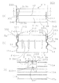
次に、本発明の第5施形態のバスダクトプラグインホール保護構造400について、図14乃至図16を用いて説明する。尚、図14は、本発明の第5実施形態のバスダクトプラグインホール保護構造のバスダクトを示す図であり、(a)が平面図であり、(b)が側面図である。また、図15は、本発明の第5実施形態のバスダクトプラグインホール保護構造及びバスダクトの詳細を示す図であり、(a)が平面図であり、(b)がK−Kの模式断面図であり、(c)がL−Lの模式断面図である。また、図16は、本発明の第5実施形態のバスダクトプラグインホール保護構造のプラグインホールにプラグイン装置を挿入する過程を示す模式図であり、(a)が挿入前の図、(b)が指示円S4部分の拡大図(挿入前)、(c)が指示円S4部分の拡大図(ロック解除状態)、(d)が指示円S4部分の拡大図(挿入後)である。
<< 5th Embodiment >>
Next, a bus duct plug-in hole protection structure 400 according to a fifth embodiment of the present invention will be described with reference to FIGS. FIG. 14 is a view showing a bus duct having a bus duct plug-in hole protection structure according to a fifth embodiment of the present invention, wherein (a) is a plan view and (b) is a side view. FIGS. 15A and 15B are diagrams showing details of the bus duct plug-in hole protection structure and the bus duct according to the fifth embodiment of the present invention, wherein FIG. 15A is a plan view and FIG. 15B is a schematic cross-sectional view of KK. (C) is a schematic cross-sectional view of L-L. FIG. 16 is a schematic view showing a process of inserting the plug-in device into the plug-in hole of the bus duct plug-in hole protection structure according to the fifth embodiment of the present invention. FIG. ) Is an enlarged view of the instruction circle S4 (before insertion), (c) is an enlarged view of the instruction circle S4 (unlocked state), and (d) is an enlarged view of the instruction circle S4 (after insertion).

尚、第5実施形態のバスダクトプラグインホール保護構造400は、バスダクトおよびシャッタ部材の構造が第1実施形態乃至第4実施形態とは異なる。よって、この第5実施形態では、説明の便宜上、第1実施形態乃至第4実施形態と同様の構成又は相当する部分となるものには同じ符号を付すと共に、第1実施形態乃至第4実施形態と異なる部分(すなわちバスダクトおよびシャッタ部材)を詳細に説明し、同様の構成の部分については説明を省略する。  The bus duct plug-in hole protection structure 400 according to the fifth embodiment is different from the first to fourth embodiments in the structure of the bus duct and the shutter member. Therefore, in the fifth embodiment, for convenience of explanation, the same reference numerals are given to components that are the same as or correspond to those in the first to fourth embodiments, and the first to fourth embodiments. The parts different from the above (that is, the bus duct and the shutter member) will be described in detail, and the description of the parts having the same configuration will be omitted.

第5実施形態のバスダクトプラグインホール保護構造400は、例えば図示しない絶縁性の樹脂シートで被覆されて密着並設した絶縁被覆型の複数(この場合、一例としてRST三相分の三本)のバスダクト導体402をハウジング411内部に収容したバスダクト410と、バスダクト410同士を電気的に接続するバスダクト接続部419(すなわち、接続用のバスダクト)と、バスダクト410の各バスダクト導体402それぞれに対応する複数(この場合、一例として三個)の接触子421を有するプラグイン装置420を具えている(図16参照)。  The bus duct plug-in hole protection structure 400 according to the fifth embodiment includes, for example, a plurality of insulating coating types (in this case, three RSTs for three phases) that are covered with an insulating resin sheet (not shown) and arranged in close contact with each other. A bus duct 410 accommodating the bus duct conductor 402 inside the housing 411, a bus duct connecting portion 419 for electrically connecting the bus ducts 410 (that is, a bus duct for connection), and a plurality of bus duct conductors 402 corresponding to the respective bus duct conductors 402 of the bus duct 410 ( In this case, a plug-in device 420 having three contacts 421 as an example is provided (see FIG. 16).

バスダクト接続部419では、図15に示すように、対向して配置されたバスダクト410の各相のバスダクト導体402の端部を二枚の接続導体419aで挟み、両外側にハウジングとしての側板419bを配置して、相間や側板419bとの間を絶縁セパレータ419eで絶縁し、ボルト419cで一括に締結することでバスダクト410同士を電気的に接続するようになされている。このとき、二枚の接続導体419aはバスダクト導体402よりも幅広に形成されているため、ボルト419cで締結したときにバスダクト導体402よりも上方(下方)に突き出るようになされており、この突き出た部分において、二枚の接続導体419aに挟まれたプラグイン空間419dが形成されるようになされている。  In the bus duct connecting portion 419, as shown in FIG. 15, the end portions of the bus duct conductor 402 of each phase of the bus duct 410 arranged to face each other are sandwiched between two connecting conductors 419a, and side plates 419b as housings are provided on both outer sides. The bus ducts 410 are electrically connected to each other by being arranged, insulated from each other and between the side plates 419b by an insulating separator 419e, and fastened together by a bolt 419c. At this time, since the two connection conductors 419a are formed wider than the bus duct conductor 402, the two connection conductors 419a protrude upward (downward) from the bus duct conductor 402 when fastened with the bolts 419c. In the portion, a plug-in space 419d sandwiched between two connection conductors 419a is formed.

また、バスダクト接続部419では、その上部および下部をハウジングとしての上下板419fで覆っており、この上下板にプラグインホール12が形成され、ここにシャッタ部材413が取り付けられる(この場合は一例として上側のみに形成)。そして、シャッタ部材413を介したプラグインホール12にプラグイン装置420の接触子421が挿入され、且つ、プラグイン空間419dに挿入(プラグイン)されると、接続導体419aに接続されることにより、電気幹線の主幹としてのバスダクト410に対してプラグイン装置420が電気的に接続されるようになっている。  Further, the upper and lower portions of the bus duct connecting portion 419 are covered with upper and lower plates 419f as housings, and plug-in holes 12 are formed on the upper and lower plates, and a shutter member 413 is attached thereto (in this case, as an example) Formed only on the upper side). Then, when the contact 421 of the plug-in device 420 is inserted into the plug-in hole 12 via the shutter member 413 and is inserted into the plug-in space 419d (plug-in), it is connected to the connection conductor 419a. The plug-in device 420 is electrically connected to the bus duct 410 as the main trunk of the electric trunk line.

ここで、先ず、第5実施形態のバスダクトプラグインホール保護構造400における、シャッタ部材413について説明する。シャッタ部材413は、図15に示すように、プラグインホール12をバスダクト410の長手方向に二分するかのようにしてお互いに対向して配置された一対の第1シャッタ部材413a及び第2シャッタ部材413bとからなり、これら第1シャッタ部材413a及び第2シャッタ部材413bのそれぞれに、プラグインホール12を覆うための閉塞部413cが形成されている。また、シャッタ部材413の枠体413hにおけるバスダクト410の長手方向の両側には、第1シャッタ部材413a及び第2シャッタ部材413bの閉塞部413cをスライドして収容可能なスライド穴413dが枠体413hに囲まれた内側の領域に穿設されている。尚、枠体413hで囲まれた領域も便宜的にプラグインホール12とする。  First, the shutter member 413 in the bus duct plug-in hole protection structure 400 of the fifth embodiment will be described. As shown in FIG. 15, the shutter member 413 includes a pair of first shutter member 413 a and second shutter member that are arranged to face each other as if the plug-in hole 12 is divided into two in the longitudinal direction of the bus duct 410. The first shutter member 413a and the second shutter member 413b are each formed with a closing portion 413c for covering the plug-in hole 12. In addition, on both sides of the bus duct 410 in the longitudinal direction of the frame body 413h of the shutter member 413, there are slide holes 413d in the frame body 413h that can be accommodated by sliding the closing portions 413c of the first shutter member 413a and the second shutter member 413b. It is drilled in the enclosed inner area. The region surrounded by the frame body 413h is also referred to as a plug-in hole 12 for convenience.

従って、第1シャッタ部材413a及び第2シャッタ部材413bの閉塞部413cそれぞれを、スライド穴413dに挿入することで、第1シャッタ部材413a及び第2シャッタ部材413bは、プラグインホール12を両開き式にスライド開閉できるようになされている。  Therefore, by inserting the closing portions 413c of the first shutter member 413a and the second shutter member 413b into the slide holes 413d, the first shutter member 413a and the second shutter member 413b open the plug-in hole 12 in a double-open manner. The slide can be opened and closed.

また、第1シャッタ部材413a及び第2シャッタ部材413bには、プラグインホール12の閉塞時に相互に接触する閉塞部413cの端辺の少なくとも一部に、プラグインホール12の外方から内方に向けて傾斜するシャッタ開放ガイド部413eが設けられている。このシャッタ開放ガイド部413eに対し、後述するプラグイン装置420の接触子421(シャッタ開放部)が押し当てられることによって、プラグイン装置420を挿入する方向の動きが第1シャッタ部材413a及び第2シャッタ部材413bを開放方向にスライドさせる動きに変換されるようになされている。  In addition, the first shutter member 413a and the second shutter member 413b have at least a part of the end sides of the closing portion 413c that contact each other when the plug-in hole 12 is closed, from the outside of the plug-in hole 12 to the inside. A shutter opening guide portion 413e that is inclined toward the surface is provided. A contact 421 (shutter opening portion) of the plug-in device 420 described later is pressed against the shutter opening guide portion 413e, so that the movement in the direction in which the plug-in device 420 is inserted changes the first shutter member 413a and the second shutter member 413a. The shutter member 413b is converted into a movement that slides in the opening direction.

尚、スライド穴413dの中には、プラグインホール12を閉塞する方向に第1シャッタ部材413a及び第2シャッタ部材413bを付勢するための例えば螺旋(コイル)状のバネ部材416が設けられており、これにより、第1シャッタ部材413a及び第2シャッタ部材413bが付勢されてプラグインホール12を閉塞するようになされている。  In the slide hole 413d, for example, a spiral (coil) spring member 416 for biasing the first shutter member 413a and the second shutter member 413b in a direction to close the plug-in hole 12 is provided. Accordingly, the first shutter member 413a and the second shutter member 413b are urged to close the plug-in hole 12.

次に、第5実施形態のバスダクトプラグインホール保護構造400における、シャッタ部材413のロック機構について説明する。このロック機構は、ロック状態において第1シャッタ部材413a及び第2シャッタ部材413bが両開きにスライドしてプラグインホール12を開放しないように維持しつつ、ロックが解除された場合には開放できるようにするためのものであり、図15及び図16に示すように、第1シャッタ部材413a及び第2シャッタ部材413bが閉塞状態において突き合わされている部分の端部近傍において、ロック部材430を枠体413hから延設するように一体に設けることによって実現される。  Next, a lock mechanism for the shutter member 413 in the bus duct plug-in hole protection structure 400 of the fifth embodiment will be described. This lock mechanism can be opened when the lock is released while the first shutter member 413a and the second shutter member 413b are not slid to open in the locked state to keep the plug-in hole 12 open. 15 and 16, as shown in FIGS. 15 and 16, in the vicinity of the end of the portion where the first shutter member 413a and the second shutter member 413b are in a closed state, the lock member 430 is attached to the frame body 413h. It implement | achieves by providing integrally so that it may extend from.

具体的には、ロック部材430は、枠体413hの内壁の下方から上方に向けて弾性変形可能な程度の強度で延設されており、その先端には、第1シャッタ部材413a及び第2シャッタ部材413bが閉塞状態において突き合わされている部分の端部の上側に配置される被ロック解除部431が設けられている。  Specifically, the lock member 430 is extended with a strength that can be elastically deformed from the lower side to the upper side of the inner wall of the frame 413h, and the first shutter member 413a and the second shutter are provided at the tip thereof. There is provided an unlocked portion 431 disposed above the end of the portion where the member 413b is abutted in the closed state.

また、ロック部材430には、閉塞状態における第1シャッタ部材413a及び第2シャッタ部材413bそれぞれの閉塞部413cの下側でシャッタ開放ガイド部413eの裏側の部分を係止するように、一対のロック部432が設けられており、第1シャッタ部材413a及び第2シャッタ部材413b側へのロック部432の突出幅は、被ロック解除部431の突出幅より短く形成されている。  In addition, the lock member 430 has a pair of locks so that the back side portion of the shutter opening guide portion 413e is locked below the closing portion 413c of each of the first shutter member 413a and the second shutter member 413b in the closed state. A portion 432 is provided, and the protruding width of the lock portion 432 toward the first shutter member 413 a and the second shutter member 413 b is formed shorter than the protruding width of the unlocked portion 431.

ロック部432は、閉塞状態における第1シャッタ部材413a及び第2シャッタ部材413bのシャッタ開放ガイド部413eの裏側の部分に配置されることで、開放ガイド部413eを係止し、第1シャッタ部材413a及び第2シャッタ部材413bがスライドしてプラグインホール12を開放することを防止(すなわちロック)するようになされている。すなわちこれがロック状態である。  The lock part 432 is disposed on the back side of the shutter opening guide part 413e of the first shutter member 413a and the second shutter member 413b in the closed state, thereby locking the opening guide part 413e and locking the first shutter member 413a. The second shutter member 413b is prevented from sliding (ie, locked) by opening the plug-in hole 12. That is, this is a locked state.

かかる構成に加え、シャッタ部材413において枠体413hとロック部材430との間には、ロック部材430が枠体413h側へ押されたときに変形して反ることができるようにするためのロック部材収納空間440が形成されている。  In addition to such a configuration, a lock is provided between the frame member 413h and the lock member 430 in the shutter member 413 so that the lock member 430 can be deformed and warped when the lock member 430 is pushed toward the frame member 413h. A member storage space 440 is formed.

これにより、第5実施形態のバスダクトプラグインホール保護構造400は、ロック部材430の弾性力を越える力で被ロック解除部431が枠体413h側に押されると、ロック部材430が変形して枠体413h側へ反ってロック部材収納空間440に収容された状態になる。このとき、ロック部材430のロック部432も枠体413h側へ反ることにより、ロック部432による係止が外れ、第1シャッタ部材413a及び第2シャッタ部材413bがスライドして開くことができるようになされている。すなわちこれがロック解除状態である。  Accordingly, in the bus duct plug-in hole protection structure 400 according to the fifth embodiment, when the unlocked portion 431 is pushed toward the frame body 413h by a force exceeding the elastic force of the lock member 430, the lock member 430 is deformed and the frame It will be in the state accommodated in the lock member accommodation space 440 while warping to the body 413h side. At this time, the lock portion 432 of the lock member 430 is also warped toward the frame body 413h, so that the lock portion 432 is unlocked, and the first shutter member 413a and the second shutter member 413b can be slid and opened. Has been made. That is, this is the unlocked state.

このようにして、第5実施形態のバスダクトプラグインホール保護構造400においても、第3実施形態及び第4実施形態と同様に、第1シャッタ部材413a及び第2シャッタ部材413bがスライドしてプラグインホール12を開放することのロックと解除(すなわち、ロックのON/OFF)ができるようになされている。  As described above, also in the bus duct plug-in hole protection structure 400 of the fifth embodiment, the first shutter member 413a and the second shutter member 413b slide and plug in as in the third and fourth embodiments. The opening and closing of the hole 12 can be locked and released (that is, the lock is turned on / off).

次に、第5実施形態のバスダクトプラグインホール保護構造400における、ロック解除機構について説明する。このロック解除機構に関し、まず、第4実施形態のバスダクトプラグインホール保護構造400を構成するプラグイン装置420について、第1実施形態乃至第4実施形態のプラグイン装置とは異なる部分を説明する。  Next, the lock release mechanism in the bus duct plug-in hole protection structure 400 of the fifth embodiment will be described. Regarding this unlocking mechanism, first, the plug-in device 420 constituting the bus duct plug-in hole protection structure 400 of the fourth embodiment will be described with respect to the parts different from the plug-in devices of the first to fourth embodiments.

プラグイン装置420は、図16に示すように、遮断器等(図示せず)を内部に収納した箱形状の本体部422と、バスダクト410の各バスダクト導体402それぞれに対応して本体部422から突設された複数(この場合、一例として三個)の接触子421と、この接触子421を支持すると共に保護するための絶縁樹脂製の絶縁ホルダ423とを有している。そして、この第5実施形態のバスダクトプラグインホール保護構造400におけるプラグイン装置420では、接触子421がロック解除部として機能すると共に、シャッタ開放部としても機能するようになされている。  As shown in FIG. 16, the plug-in device 420 includes a box-shaped main body 422 in which a circuit breaker (not shown) is housed and a main body 422 corresponding to each bus duct conductor 402 of the bus duct 410. A plurality of (in this case, three as an example) contactors 421 provided in a projecting manner and an insulating resin-made insulating holder 423 for supporting and protecting the contactors 421 are provided. In the plug-in device 420 in the bus duct plug-in hole protection structure 400 according to the fifth embodiment, the contact 421 functions as an unlocking unit and also functions as a shutter opening unit.

具体的には、接触子421は、バスダクト410の長手方向に沿って見たときに、一対の端子が先細りで中央付近が外側に丸く膨らむような形状になるように横並びで配置されている。この一対の端子が、二枚の接続導体419aの間のプラグイン空間419dに接触子421を挿入し易いように挿入ガイド421aとして形成されている。そして、三個並んだ接触子421の挿入ガイド421aのうち、両外側に位置する挿入ガイド421aがロック解除部としても機能するようになされている。  Specifically, the contacts 421 are arranged side by side so that when viewed along the longitudinal direction of the bus duct 410, the pair of terminals are tapered and the vicinity of the center bulges outward. The pair of terminals is formed as an insertion guide 421a so that the contact 421 can be easily inserted into the plug-in space 419d between the two connection conductors 419a. Of the insertion guides 421a of the three contact elements 421 arranged side by side, the insertion guides 421a located on both outer sides function as a lock release portion.

また、接触子421は、バスダクト410の長手方向に直交する方向に沿って見たときに、端子が下方の先端に向けて先細りの逆三角形状に形成されており、この部分がシャッタ開放部421bとして機能する。  Further, when the contact 421 is viewed along a direction orthogonal to the longitudinal direction of the bus duct 410, the terminal is formed in an inverted triangular shape that tapers toward the lower end, and this portion is the shutter opening portion 421b. Function as.

一方で、第5実施形態のバスダクトプラグインホール保護構造400において、ロック部材430の被ロック解除部431は、その端部に上方から下方に傾斜する斜辺が形成されている。  On the other hand, in the bus duct plug-in hole protection structure 400 of the fifth embodiment, the unlocked portion 431 of the lock member 430 is formed with a hypotenuse that slopes downward from above at the end thereof.

この被ロック解除部431に対し、プラグイン装置420の接触子421の挿入ガイド421a(ロック解除部)がプラグイン装置420の挿入方向に押し当てられると、プラグイン装置420を挿入する方向の動作が被ロック解除部431を枠体413h側に押圧する動作に変換され、これにより、ロック部材430が変形して枠体413h側へ反ってロック部材収納空間440に収容される。このとき、ロック部材430のロック部432も枠体413h側へ反ることにより、ロック部432による係止が外れ、その結果、ロックが解除されるようになされている。  When the insertion guide 421a (lock release portion) of the contact 421 of the plug-in device 420 is pressed against the unlocked portion 431 in the insertion direction of the plug-in device 420, the operation in the direction of inserting the plug-in device 420 is performed. Is converted into an operation of pressing the unlocked portion 431 toward the frame body 413h, whereby the lock member 430 is deformed and warped toward the frame body 413h and accommodated in the lock member storage space 440. At this time, the lock portion 432 of the lock member 430 is also warped toward the frame body 413h, so that the lock portion 432 is disengaged, and as a result, the lock is released.

このようにして、第5実施形態のバスダクトプラグインホール保護構造400では、第1シャッタ部材413a及び第2シャッタ部材413bのロックが、プラグイン装置420の挿入によって解除されるようになされている。  Thus, in the bus duct plug-in hole protection structure 400 according to the fifth embodiment, the lock of the first shutter member 413a and the second shutter member 413b is released by inserting the plug-in device 420.

すなわち、第5実施形態のバスダクトプラグインホール保護構造400では、ロック部材430が設けられて第1シャッタ部材413a及び第2シャッタ部材413bが開くことを防止する一方で、プラグインホール12へのプラグイン装置420の挿入動作に応じ、ロック部材430によるロックを解除できるようになされている。これにより、例えば作業者が不用意にシャッタ部材413に触れてしまうような場合には、ロックされているため第1シャッタ部材413a及び第2シャッタ部材413bが開くことはなく、プラグインホール12の保護がより一層強固なものとなる。その一方で、プラグインホール12にプラグイン装置420を近づけて挿入する際に、第1シャッタ部材413a及び第2シャッタ部材413bのロックが自動で解除されるため、施工性に何ら影響することなくスムーズな挿入が可能である。  That is, in the bus duct plug-in hole protection structure 400 of the fifth embodiment, the lock member 430 is provided to prevent the first shutter member 413a and the second shutter member 413b from opening, while the plug to the plug-in hole 12 is plugged. The lock by the lock member 430 can be released in accordance with the insertion operation of the in-device 420. As a result, for example, when an operator inadvertently touches the shutter member 413, the first shutter member 413a and the second shutter member 413b are not opened because they are locked, and the plug-in hole 12 Protection becomes even stronger. On the other hand, when the plug-in device 420 is inserted close to the plug-in hole 12, the first shutter member 413a and the second shutter member 413b are automatically unlocked without affecting the workability. Smooth insertion is possible.

また、第5実施形態のバスダクトプラグインホール保護構造400では、ロック部材430の被ロック解除部431が外部(上方)へと露出しており、容易に視認できるようになっている。これにより、ロックされているか否かが一目で判別でき、例えば、仮に何らかの要因によってロック部材430に不具合があって、ロックされているべき状況においてロックされていないような状態が生じたとしても、シャッタ部材を押して確認する等の作業をすることなく目視だけで不具合を判別することができる。  In the bus duct plug-in hole protection structure 400 of the fifth embodiment, the unlocked portion 431 of the lock member 430 is exposed to the outside (upward) so that it can be easily seen. As a result, it can be determined at a glance whether or not it is locked.For example, even if there is a problem with the lock member 430 due to some factor, and a state where the lock member 430 is not locked in a situation where it should be locked occurs, A defect can be determined by visual observation without performing an operation such as checking by pressing the shutter member.

これに加え、第5実施形態のバスダクトプラグインホール保護構造400では、ロック部材430の被ロック解除部431が、第1シャッタ部材413a及び第2シャッタ部材413bよりも外部(上方)に配置されている。これにより、ロック機能を有しつつも、メンテナンス等でシャッタ部材を開けたい場合には、被ロック解除部431を直接操作して容易にロックを解除でき、シャッタ部材を開放することができる。  In addition, in the bus duct plug-in hole protection structure 400 of the fifth embodiment, the unlocked portion 431 of the lock member 430 is disposed outside (above) the first shutter member 413a and the second shutter member 413b. Yes. Accordingly, when it is desired to open the shutter member for maintenance or the like while having a lock function, the lock can be easily released by directly operating the unlocked portion 431 and the shutter member can be opened.

また、第5実施形態のバスダクトプラグインホール保護構造400では、プラグインホール12の平面視において、ロック部材430の被ロック解除部431がプラグインホール12の領域の内側に配置されている。このため、プラグインホール12の平面視において被ロック解除部431がプラグインホールの領域の外側になるように配置する場合に比べてバスダクトプラグインホール保護構造400を設けるのに必要なスペースを小さくすることができ、その結果、バスダクトプラグインホール保護構造がコンパクトになる。  Further, in the bus duct plug-in hole protection structure 400 according to the fifth embodiment, the unlocked portion 431 of the lock member 430 is disposed inside the region of the plug-in hole 12 in the plan view of the plug-in hole 12. For this reason, the space required for providing the bus duct plug-in hole protection structure 400 is reduced as compared with the case where the unlocked portion 431 is disposed outside the plug-in hole region in plan view of the plug-in hole 12. As a result, the bus duct plug-in hole protection structure becomes compact.

また、第5実施形態のバスダクトプラグインホール保護構造400では、プラグイン装置420に分岐用の接触子421が設けられ、この接触子421の挿入ガイド421aがロック解除部の機能を有するようにしていると共に、接触子421のシャッタ開放部421bがシャッタ開放部の機能を有するようにしている。このため、ロック解除部やシャッタ開放部を別部材や別形状として形成する必要が無いため、構造がシンプルとなり製造コストも安くなる。  Further, in the bus duct plug-in hole protection structure 400 according to the fifth embodiment, the plug-in device 420 is provided with a branching contact 421, and the insertion guide 421a of the contact 421 has a function of an unlocking portion. In addition, the shutter opening portion 421b of the contact 421 has a function of a shutter opening portion. For this reason, it is not necessary to form the unlocking portion and the shutter opening portion as separate members or shapes, so that the structure is simple and the manufacturing cost is reduced.

かかる構成に加え、第5実施形態のバスダクトプラグインホール保護構造400では、プラグイン装置420に分岐用の接触子421を保護する絶縁ホルダ423にも、ロック解除部として機能する第1斜辺423aが形成されていると共に、シャッタ開放部として機能する第2斜辺423bが形成されている。すなわち、第5実施形態のバスダクトプラグインホール保護構造400では、プラグイン装置420の接触子421と絶縁ホルダ423との両方が、ロック解除部の機能を有すると共にシャッタ開放部の機能を有するようにもなされている。尚、接触子421及び絶縁ホルダ423の形状や寸法を選定することで、接触子421だけにロック解除部の機能およびシャッタ開放部の機能の少なくとも一方を付与するようにしても良い。  In addition to this configuration, in the bus duct plug-in hole protection structure 400 of the fifth embodiment, the insulating holder 423 that protects the branching contact 421 in the plug-in device 420 also has a first oblique side 423a that functions as an unlocking portion. A second oblique side 423b that functions as a shutter opening portion is formed. That is, in the bus duct plug-in hole protection structure 400 of the fifth embodiment, both the contact 421 and the insulating holder 423 of the plug-in device 420 have a function of an unlocking part and a function of a shutter opening part. It has also been made. Note that by selecting the shapes and dimensions of the contact 421 and the insulating holder 423, at least one of the function of the unlocking portion and the function of the shutter opening portion may be given only to the contact 421.

以下、第5実施形態のバスダクトプラグインホール保護構造400において、プラグインホール12に対してプラグイン装置420を挿入する際のシャッタ部材413及びロック部材430の動作について図16を用いて説明する。  Hereinafter, the operation of the shutter member 413 and the lock member 430 when the plug-in device 420 is inserted into the plug-in hole 12 in the bus duct plug-in hole protection structure 400 of the fifth embodiment will be described with reference to FIG.

図16(a)及び(b)は、プラグインホール12に対してプラグイン装置420を挿入する前の状態を示す図であり、三個並んだ接触子421の挿入ガイド421aのうちの両外側に位置する挿入ガイド421a(ロック解除部)が被ロック解除部431の略直上に位置するようにプラグイン装置420が配置されている。  FIGS. 16A and 16B are views showing a state before the plug-in device 420 is inserted into the plug-in hole 12, and both outer sides of the insertion guides 421a of the three contact elements 421 arranged side by side. The plug-in device 420 is arranged so that the insertion guide 421a (unlocking part) located at the position is located almost directly above the unlocked part 431.

図16(c)は、プラグインホール12に対してプラグイン装置420を挿入する動作が開始された結果、三個並んだ接触子421の挿入ガイド421aのうちの両外側に位置する挿入ガイド421aそれぞれが被ロック解除部431を押圧してロック部材430全体を枠体413h側へ反らせてロック部材収納空間440に収容させた状態を示す図であり、ロック部材430のロック部432も枠体413h側へ反ることにより、ロック部432による係止が外れてロックが解除され、第1シャッタ部材413a及び第2シャッタ部材413bがスライドして開くことができる状態となっている。  FIG. 16C shows the insertion guides 421a located on both outer sides of the insertion guides 421a of the three contacts 421 arranged as a result of the operation of inserting the plug-in device 420 into the plug-in hole 12 being started. Each of the drawings shows a state in which the unlocked portion 431 is pressed and the entire lock member 430 is bent toward the frame body 413h and accommodated in the lock member storage space 440. The lock portion 432 of the lock member 430 is also the frame body 413h. By warping to the side, the locking by the lock portion 432 is released and the lock is released, and the first shutter member 413a and the second shutter member 413b can be slid and opened.

図16(d)は、プラグインホール12に対してプラグイン装置420を挿入する動作が完了した状態を示す図であり、接触子421の略三角形状のシャッタ開放部421bの先端が第1シャッタ部材413aのシャッタ開放ガイド部413eと第2シャッタ部材413bのシャッタ開放ガイド部413eとに接触し、第1シャッタ部材413aと第2シャッタ部材413bとが離間する方向にスライドさせている。すなわち、シャッタ開放ガイド部413eに対して略三角形状のシャッタ開放部421bが押し当てられることによって、プラグイン装置420を挿入する方向の動作が第1シャッタ部材413a及び第2シャッタ部材413bを開放方向にスライドさせる動作に変換されており、その力がバネ部材416の付勢力を越えたときに、プラグインホール12が開放されていくようになされている。  FIG. 16D is a diagram illustrating a state in which the operation of inserting the plug-in device 420 into the plug-in hole 12 is completed, and the tip of the substantially triangular shutter opening 421b of the contact 421 is the first shutter. The shutter opening guide portion 413e of the member 413a and the shutter opening guide portion 413e of the second shutter member 413b are in contact with each other, and the first shutter member 413a and the second shutter member 413b are slid in a direction away from each other. That is, when the substantially triangular shutter opening portion 421b is pressed against the shutter opening guide portion 413e, the operation in the direction in which the plug-in device 420 is inserted opens the first shutter member 413a and the second shutter member 413b. The plug-in hole 12 is opened when the force exceeds the urging force of the spring member 416.

このように、第5実施形態のバスダクトプラグインホール保護構造400は、バスダクト410(バスダクト接続部419)のプラグインホール12に対するプラグイン装置420の挿入動作により、図16(b)→(c)→(d)のように、第1シャッタ部材413a及び第2シャッタ部材413bのロックを自動で解除しつつ、これら、第1シャッタ部材413a及び第2シャッタ部材413bを自動で開放するようになされている。  As described above, the bus duct plug-in hole protection structure 400 according to the fifth embodiment is configured so that the plug-in device 420 is inserted into the plug-in hole 12 of the bus duct 410 (bus duct connection portion 419) as shown in FIG. → As shown in (d), the first shutter member 413a and the second shutter member 413b are automatically opened while the first shutter member 413a and the second shutter member 413b are automatically unlocked. Yes.

また、第5実施形態のバスダクトプラグインホール保護構造400において、プラグインホール12からプラグイン装置420を引き抜く際のシャッタ部材413の動作については、第1シャッタ部材413a及び第2シャッタ部材413bがバネ部材416によってプラグインホール12の閉塞方向に常に付勢されているため、単純に挿入時とは逆の動作となり、図16(d)→(c)→(b)のように、第1シャッタ部材413a及び第2シャッタ部材413bが自動で閉塞した後に、ロック部材430が弾性力によって元の位置に戻ることで自動にロックされるようになされている。  In the bus duct plug-in hole protection structure 400 according to the fifth embodiment, regarding the operation of the shutter member 413 when the plug-in device 420 is pulled out from the plug-in hole 12, the first shutter member 413a and the second shutter member 413b are springs. Since the member 416 always urges the plug-in hole 12 in the closing direction, the operation is simply the reverse of the insertion, and the first shutter as shown in FIGS. 16 (d) → (c) → (b). After the member 413a and the second shutter member 413b are automatically closed, the lock member 430 is automatically locked by returning to the original position by elastic force.

以上説明したように、第5実施形態のバスダクトプラグインホール保護構造400は、プラグインホール12にプラグイン装置420を近づけて挿入する際に、シャッタ部材413のロックが自動で解除されるため、施工性に何ら影響することなくスムーズな挿入が可能である。その一方で、例えば作業者が不用意にシャッタ部材413に触れてしまうような場合には、ロックされているためシャッタ部材が開くことはなく、プラグインホール12の保護がより一層強固なものとなる。  As described above, the bus duct plug-in hole protection structure 400 of the fifth embodiment automatically releases the lock of the shutter member 413 when the plug-in device 420 is inserted close to the plug-in hole 12. Smooth insertion is possible without affecting the workability. On the other hand, for example, when an operator inadvertently touches the shutter member 413, the shutter member does not open because it is locked, and the plug-in hole 12 is further protected. Become.

《他の実施形態》
尚、上述した実施の形態では、RST三相+中性相の四本のバスダクト導体(三相四線)や、RST三相だけの三本のバスダクト導体(三相三線)を有するバスダクトについて説明したが、本発明はこれに限らず、単相一線・単相二線・単相三線・三相六線・三相八線、等、バスダクト導体の相数や導体の線数は適宜であるものとする。
<< Other embodiments >>
In the embodiment described above, a bus duct having four bus duct conductors (three-phase four-wire) of RST three-phase + neutral phase and three bus duct conductors (three-phase three-wire) having only RST three-phase is described. However, the present invention is not limited to this, and the number of phases of the bus duct conductor and the number of conductors are appropriate, such as single-phase one-wire, single-phase two-wire, single-phase three-wire, three-phase six-wire, three-phase eight-wire, etc. Shall.

また、上述した第1乃至第4実施形態では、突出部としてハウジング11の補強部14を適用し、突出空間としてハウジング11の補強空間15(15a・15b・15c)を適用するようにした場合について述べたが、本発明はこれに限らず、例えば意匠用や部材セット用の凹部といった、補強用途ではない突出部及び突出空間を用いるようにしても良い。  In the first to fourth embodiments described above, the reinforcing portion 14 of the housing 11 is applied as the protruding portion, and the reinforcing space 15 (15a, 15b, 15c) of the housing 11 is applied as the protruding space. Although described above, this invention is not restricted to this, For example, you may make it use the protrusion part and protrusion space which are not a reinforcement use, such as a recessed part for designs or a member set.

また、上述した第1及び第2実施形態では、上側ハウジング半体11aおよび下側ハウジング半体11bの両側壁に補強部14および補強空間15を形成するようにした場合について述べたが、本発明はこれに限らず、上側ハウジング半体11aの上板や下側ハウジング半体11bの下板を略凸形状に突出変形させることによって補強部や補強空間を形成するようにしても良く、そのようにして形成された補強空間にシャッタ部材の一部やバネ部材が収納されるようにシャッタ部材を配置しても良い。  In the first and second embodiments described above, the case where the reinforcing portion 14 and the reinforcing space 15 are formed on both side walls of the upper housing half 11a and the lower housing half 11b has been described. However, the present invention is not limited to this, and the reinforcing plate and the reinforcing space may be formed by projecting and deforming the upper plate of the upper housing half 11a and the lower plate of the lower housing half 11b into a substantially convex shape. The shutter member may be arranged so that a part of the shutter member or the spring member is accommodated in the reinforcing space formed as described above.

また、上述した第1及び第2実施形態では、補強空間15a・補強空間15b・補強空間15cのうちの補強空間15aに対してプラグインホール12を閉塞することに関わる部材の一部を配置するようにした場合について述べたが、本発明はこれに限らず、補強空間15bや補強空間15cを利用する構成であってもよい。また、ハウジング11の両側壁の補強空間15aにそれぞれバネ部材や規制部を設けるようにした場合について述べたが、片側だけに設けるようにしても良い。また、一方にはバネ部材を他方には規制部を設けるようにしても良い。  In the first and second embodiments described above, a part of the member related to closing the plug-in hole 12 with respect to the reinforcing space 15a among the reinforcing space 15a, the reinforcing space 15b, and the reinforcing space 15c is disposed. Although the case where it did in this way was described, this invention is not restricted to this, The structure using the reinforcement space 15b and the reinforcement space 15c may be sufficient. Moreover, although the case where the spring member and the restricting portion are provided in the reinforcing spaces 15a on the both side walls of the housing 11 has been described, it may be provided only on one side. Further, a spring member may be provided on one side and a restricting portion may be provided on the other side.

また、上述した第1及び第2実施形態では、プラグインホール12を閉塞することに関わる部材として、シャッタ部材13の一部、バネ部材16(116)及び規制部17を補強空間15aに収容するようにした場合について述べたが、その全体を収容してもよいし、一部を収容してもよいし、いずれかの部材だけを収容してもよく、要は、プラグインホール12を閉塞することに関わる部材の一部が補強空間15a(突出空間)に収容されていれば、バスダクト導体2とハウジング11との間の空間絶縁距離や沿面距離等を阻害しにくくなる。  In the first and second embodiments described above, a part of the shutter member 13, the spring member 16 (116), and the restricting portion 17 are housed in the reinforcing space 15 a as members involved in closing the plug-in hole 12. Although the case where it did so was described, the whole may be accommodated, a part may be accommodated, and only one of the members may be accommodated. In short, the plug-in hole 12 is closed. If a part of the members involved in the operation is accommodated in the reinforcing space 15a (projecting space), it is difficult to hinder the space insulation distance, the creepage distance, and the like between the bus duct conductor 2 and the housing 11.

また、上述した第1乃至第5実施形態では、螺旋(コイル)状のバネ部材や板状のバネ部材を用いるようにした場合について述べたが、本発明はこれに限らず、バネ部材としては弾性を有する部材を用いればよく、金属材料、ゴム状の物質や軟質樹脂、木片や竹片等の植物材料品及びその加工物、等何でもよいし、その形状も蛇腹状等でもよい。また、このバネ部材とシャッタ部材とを連結する部位やその構造についても、特に限定しない。  In the first to fifth embodiments described above, the case where a spiral (coil) -like spring member or a plate-like spring member is used has been described. However, the present invention is not limited thereto, and the spring member may be used as a spring member. An elastic member may be used, and any material such as a metal material, a rubber-like substance, a soft resin, a plant material product such as a piece of wood or bamboo, and a processed product thereof may be used. Also, there is no particular limitation on the portion connecting the spring member and the shutter member and the structure thereof.

また、上述した第1乃至第5実施形態では、プラグインホール12の略中央付近で第1シャッタ部材と第2シャッタ部材とが突き合わされるようにした場合について述べたが、本発明はこれに限らず、第1シャッタ部材と第2シャッタ部材とが突き合わされた部分が、第1シャッタ部材及び第2シャッタ部材のどちらかに偏っていても良い。  In the first to fifth embodiments described above, the case where the first shutter member and the second shutter member are brought into contact with each other in the vicinity of the approximate center of the plug-in hole 12 has been described. Not limited to this, the portion where the first shutter member and the second shutter member are abutted may be biased to either the first shutter member or the second shutter member.

また、上述した第1乃至第5実施形態では、遮断器等を内部に収納した箱形状のプラグイン装置を用いるようにした場合について述べたが、本発明はこれに限らず、プラグイン装置の形状は特に限定しないし、遮断器等を内部に備えていなくてもよい。  In the first to fifth embodiments described above, the case of using a box-shaped plug-in device in which a circuit breaker and the like are housed is described. However, the present invention is not limited to this, and the plug-in device The shape is not particularly limited, and a circuit breaker or the like may not be provided inside.

また、上述した第1乃至第3実施形態では、略三角形状のシャッタ開放部によって第1シャッタ部材及び第2シャッタ部材を開放するようにした場合について述べたが、本発明はこれに限らず、下方が先細りの台形状や円弧形状等、挿入時に第1シャッタ部材及び第2シャッタ部材に引っかからない形状であれば何でも良いものとする。  In the first to third embodiments described above, the case where the first shutter member and the second shutter member are opened by the substantially triangular shutter opening portion is described. However, the present invention is not limited to this. Any shape that does not catch on the first shutter member and the second shutter member at the time of insertion, such as a tapered trapezoidal shape or an arc shape below, may be used.

また、上述した第1及び第2実施形態では、図4及び図6に示すように、シャッタ開放部24の略三角形状の開放片24aの斜辺の角度よりも第1シャッタ部材13a及び第2シャッタ部材13bのシャッタ開放ガイド部13eの傾斜角度の方が急勾配にした場合について述べたが、本発明はこれに限らず、開放片24aの斜辺の角度の方を急勾配にしても良いし、角度を合わせるようにしても良い。すなわち、開放片24aの斜辺の角度よりもシャッタ開放ガイド部13eの傾斜角度の方が急勾配にした場合は、少ない挿入量で第1シャッタ部材13a及び第2シャッタ部材13bを開放できるという利点がある。また、開放片24aの斜辺の角度をシャッタ開放ガイド部13eの傾斜角度よりも急勾配にした場合は、より少ない力で第1シャッタ部材13a及び第2シャッタ部材13bを開放できるという利点がある。さらに、開放片24aの斜辺の角度とシャッタ開放ガイド部13eの傾斜角度とを合わせた場合は、開放片24aの斜辺全体でシャッタ開放ガイド部13eを押圧できるため、挿入の力が安定して第1シャッタ部材13a及び第2シャッタ部材13bに伝わるという利点がある。  In the first and second embodiments described above, as shown in FIGS. 4 and 6, the first shutter member 13 a and the second shutter are more inclined than the angle of the oblique side of the substantially triangular opening piece 24 a of the shutter opening portion 24. Although the case where the inclination angle of the shutter opening guide portion 13e of the member 13b is steeper has been described, the present invention is not limited to this, and the angle of the oblique side of the opening piece 24a may be steeper, You may make it match an angle. That is, when the inclination angle of the shutter opening guide portion 13e is steeper than the angle of the oblique side of the opening piece 24a, there is an advantage that the first shutter member 13a and the second shutter member 13b can be opened with a small insertion amount. is there. Further, when the angle of the oblique side of the opening piece 24a is made steeper than the inclination angle of the shutter opening guide portion 13e, there is an advantage that the first shutter member 13a and the second shutter member 13b can be opened with less force. Further, when the angle of the oblique side of the opening piece 24a and the inclination angle of the shutter opening guide part 13e are matched, the shutter opening guide part 13e can be pressed by the entire oblique side of the opening piece 24a, so that the insertion force is stabilized and There is an advantage that it is transmitted to the first shutter member 13a and the second shutter member 13b.

また、上述した第3乃至第5実施形態では、バスダクト及びバスダクト接続部のハウジングに形成されたプラグインホール12に対し、枠体としてユニット化されたシャッタ部材を取付けるようにした場合について述べたが、本発明はこれに限らず、第1及び第2実施形態のように枠体を設けずにハウジングの内側にシャッタ部材を埋め込むようにしても良い。同様に、第1及び第2実施形態のシャッタ部材を、第3乃至第5実施形態のシャッタ部材のように枠体を設けてハウジングの外部に取り付けるようにしても良い。  In the third to fifth embodiments described above, the case where the shutter member unitized as a frame is attached to the plug-in hole 12 formed in the housing of the bus duct and the bus duct connecting portion has been described. The present invention is not limited to this, and a shutter member may be embedded inside the housing without providing a frame as in the first and second embodiments. Similarly, the shutter members of the first and second embodiments may be provided outside the housing by providing a frame like the shutter members of the third to fifth embodiments.

また、上述した第3実施形態では、ロック解除部60の解除片61及び解除片62を略三角形状にしてロック部材30のロック基部31の突出部分33を横断面視で矩形とするようにした場合について述べたが、本発明はこれに限らず、解除片61及び解除片62を矩形にして突出部分33を横断面視で略三角形状等にしても良いし、解除片61及び解除片62を略三角形状のままにして突出部分33を横断面視で略三角形状等にしても良い。要は、プラグイン装置220を挿入する方向の動きを、ロック部材30を枠体213h側に押圧する方向の動きに変換できるのであれば、ロック解除部60やロック部材30の各部位の形状は適宜選択可能であるものとする。第1乃至第5実施形態におけるシャッタ開放ガイド部とシャッタ開放部との関係や、被ロック解除部とロック解除部との関係も同様である。  Further, in the third embodiment described above, the release piece 61 and the release piece 62 of the lock release portion 60 are substantially triangular, and the protruding portion 33 of the lock base 31 of the lock member 30 is rectangular in a cross-sectional view. However, the present invention is not limited to this, and the release piece 61 and the release piece 62 may be rectangular, and the protruding portion 33 may have a substantially triangular shape in a cross-sectional view, or the release piece 61 and the release piece 62. May remain in a substantially triangular shape, and the protruding portion 33 may have a substantially triangular shape or the like in a cross-sectional view. In short, if the movement in the direction in which the plug-in device 220 is inserted can be converted into the movement in the direction in which the lock member 30 is pressed toward the frame body 213h, the shape of each part of the lock release portion 60 and the lock member 30 is It can be selected as appropriate. The same applies to the relationship between the shutter opening guide portion and the shutter opening portion and the relationship between the unlocked portion and the unlocking portion in the first to fifth embodiments.

また、上述した第3実施形態では、第1シャッタ部材213a及び第2シャッタ部材213bが閉塞状態において突き合わされている部分の端部にスリット213sを形成するようにした場合について述べたが、このスリット213sを裏側から閉塞できるように、第1シャッタ部材213a及び第2シャッタ部材213bの少なくとも一方の裏側に軟質樹脂製の閉塞シートを設置するようにしても良い。そうすることで、第1シャッタ部材213a及び第2シャッタ部材213bの閉塞時にはこのスリット213sも閉塞シートによって閉塞された状態となり安全性を向上でき、その一方で、プラグイン装置220のロック解除部60がスリット213sに挿入される際には、閉塞シートが変形してロック解除部60を容易に通すことが可能となり、施工性も確保できる。  In the third embodiment described above, the case where the slit 213s is formed at the end of the portion where the first shutter member 213a and the second shutter member 213b face each other in the closed state has been described. A blocking sheet made of a soft resin may be installed on at least one back side of the first shutter member 213a and the second shutter member 213b so that 213s can be closed from the back side. By doing so, when the first shutter member 213a and the second shutter member 213b are closed, the slit 213s is also closed by the closing sheet, and the safety can be improved. On the other hand, the unlocking portion 60 of the plug-in device 220 can be improved. Is inserted into the slit 213s, the closing sheet is deformed and can be easily passed through the unlocking portion 60, and workability can be ensured.

また、上述した第3実施形態では、第2シャッタ部材213bに対向する第1シャッタ部材213aの端辺の両角を矩形に切り欠くと共に、第1シャッタ部材213aに対向する第2シャッタ部材213bの端辺の両角を矩形に切り欠くことにより、その切欠き同士が合わさることでスリット213sを形成するようにした場合について述べたが、本発明はこれに限らず、第1シャッタ部材213aと第2シャッタ部材213bとのどちらかだけを切り欠くことでスリットを形成しても良いし、閉塞状態における第1シャッタ部材213aと第2シャッタ部材213bとを僅かに離間させることで微小な隙間としてのスリットを形成するようにしても良い。また、第1シャッタ部材213a及び第2シャッタ部材213bがつき合わされている部分の端部に隣接する枠体213hの内側部分を僅かに切り欠くことで、スリットを形成しても良い。  In the third embodiment described above, both corners of the edge of the first shutter member 213a facing the second shutter member 213b are cut out into a rectangular shape, and the end of the second shutter member 213b facing the first shutter member 213a. Although the case where the slits 213s are formed by cutting both corners into a rectangular shape and the cutouts are combined with each other has been described, the present invention is not limited thereto, and the first shutter member 213a and the second shutter are formed. A slit may be formed by cutting out only one of the members 213b, or a slit as a minute gap may be formed by slightly separating the first shutter member 213a and the second shutter member 213b in the closed state. You may make it form. In addition, the slit may be formed by slightly notching the inner part of the frame body 213h adjacent to the end of the part where the first shutter member 213a and the second shutter member 213b are brought together.

また、上述した第3実施形態では、ロック部材30のロック頭部32の上面が、ロック部材収納部40の上面側開口44から外部(上方)へと露出するようにした場合について述べたが、本発明はこれに限らず、例えば上面側開口44を設けないことでロック頭部32の上面を外部に露出しないようにしても良い。そうすることで、ロックされているか否かを一目で判別することはできなくなるものの、外部からロック部材30へ直接触れる可能性がある部位を減らすことができるため、その分だけ安全性を向上することができる。  In the third embodiment described above, the case where the upper surface of the lock head 32 of the lock member 30 is exposed from the upper surface side opening 44 of the lock member storage portion 40 to the outside (upward) has been described. The present invention is not limited to this. For example, the upper surface side opening 44 may not be provided so that the upper surface of the lock head 32 is not exposed to the outside. By doing so, although it becomes impossible to determine at a glance whether or not it is locked, it is possible to reduce the portion that may directly touch the lock member 30 from the outside, thus improving the safety accordingly. be able to.

また、上述した第3乃至第5実施形態では、プラグインホール12の平面視において、ロック部材の被ロック解除部がプラグインホール12の領域の内側に配置されるようにした場合について述べたが、本発明はこれに限らず、被ロック解除部の少なくとも一部がプラグインホール12の領域の内側に配置されるのであれば、その構造は特に限定しない。  In the third to fifth embodiments described above, the case where the unlocked portion of the lock member is arranged inside the region of the plug-in hole 12 in the plan view of the plug-in hole 12 has been described. The present invention is not limited to this, and the structure is not particularly limited as long as at least a part of the unlocked portion is disposed inside the region of the plug-in hole 12.

また、上述した第4実施形態では、第1シャッタ部材313a及び第2シャッタ部材313b側へのロック部332の突出幅を係止部331の突出幅より短く形成するようにした場合について述べたが、本発明はこれに限らず、係止部331が絶縁ホルダ23によって押し退けられたときに、ロック部332によるロックが解除される寸法や位置関係であるのならば、ロック部332の突出幅および係止部331の突出幅は、同じ幅でも良いしどちらが長くても良く、適宜設定できるものとする。第5実施形態についても同様である。  In the above-described fourth embodiment, the case where the protruding width of the lock portion 332 toward the first shutter member 313a and the second shutter member 313b is formed to be shorter than the protruding width of the locking portion 331 has been described. However, the present invention is not limited to this, and the protrusion width of the lock portion 332 and the lock portion 332 are determined so long as the lock portion 332 is unlocked when the locking portion 331 is pushed away by the insulating holder 23. The protrusion width of the locking portion 331 may be the same width or may be longer, and can be set as appropriate. The same applies to the fifth embodiment.

また、上述した第4実施形態では、絶縁ホルダ23の両側壁23b側の下端部23dがロック解除部の機能を有するようにしていると共に、絶縁ホルダ23の前壁23e側及び後壁23f側の下端部23gがシャッタ開放部の機能を有するようにした場合について述べたが、本発明はこれに限らず、絶縁ホルダ23の両側壁23b側の下端部23dがロック解除部の機能を有する一方でシャッタ解放部を別部材として設けるようにしても良いし、絶縁ホルダ23の前壁23e側及び後壁23f側の下端部23gがシャッタ開放部の機能を有する一方でロック解除部を別部材として設けるようにしても良い。要は、絶縁ホルダ23が有するのは、ロック解除部の機能とシャッタ解放部の機能との少なくとも一方であればよい。  Further, in the above-described fourth embodiment, the lower end portion 23d on the both side walls 23b side of the insulating holder 23 has a function of an unlocking portion, and the front wall 23e side and the rear wall 23f side of the insulating holder 23 are also provided. Although the case where the lower end portion 23g has the function of the shutter opening portion has been described, the present invention is not limited to this, while the lower end portion 23d on the both side walls 23b side of the insulating holder 23 has the function of the unlocking portion. The shutter release portion may be provided as a separate member, or the lower end portion 23g on the front wall 23e side and the rear wall 23f side of the insulating holder 23 functions as a shutter release portion, while the lock release portion is provided as a separate member. You may do it. In short, the insulating holder 23 only needs to have at least one of the function of the unlocking part and the function of the shutter releasing part.

また、上述した第5実施形態では、接触子421の挿入ガイド421aがロック解除部の機能を有するようにしていると共に、接触子421のシャッタ開放部421bがシャッタ開放部の機能を有するようにした場合について述べたが、本発明はこれに限らず、接触子421の挿入ガイド421aがロック解除部の機能を有する一方でシャッタ解放部を別部材として設けるようにしても良いし、接触子421のシャッタ開放部421bがシャッタ開放部の機能を有する一方でロック解除部を別部材として設けるようにしても良い。要は、接触子421が有するのは、ロック解除部の機能とシャッタ解放部の機能との少なくとも一方であればよい。  Further, in the fifth embodiment described above, the insertion guide 421a of the contact 421 has a function of the unlocking portion, and the shutter opening portion 421b of the contact 421 has the function of the shutter opening portion. Although the present invention is not limited to this, the insertion guide 421a of the contact 421 may function as an unlocking portion while the shutter release portion may be provided as a separate member. While the shutter opening portion 421b functions as a shutter opening portion, the unlocking portion may be provided as a separate member. In short, the contactor 421 may have at least one of the function of the unlocking part and the function of the shutter releasing part.

また、上述した第3実施形態では、スリット213sへ向けて傾斜するロック解除ガイド部213kを第1シャッタ部材213a及び第2シャッタ部材213bに形成するようにした場合について述べたが、本発明はこれに限らず、枠体213hに形成されていてもよい。すなわち、ロック解除部60が挿入されるスリット213sの周囲にロック解除ガイド部213kが形成されていれば、プラグイン装置220の挿入時においてプラグインホール12に対する位置、すなわちスリット213sに対するロック解除部60の位置が多少ずれたとしても、ロック解除部60の位置がガイド213kによって矯正されることにより、スムーズに挿入することが可能となる。  In the third embodiment described above, the case where the lock release guide portion 213k inclined toward the slit 213s is formed in the first shutter member 213a and the second shutter member 213b has been described. Not limited to this, the frame body 213h may be formed. That is, if the unlocking guide part 213k is formed around the slit 213s into which the unlocking part 60 is inserted, the position with respect to the plug-in hole 12 when the plug-in device 220 is inserted, that is, the unlocking part 60 with respect to the slit 213s. Even if the position is slightly shifted, the position of the unlocking portion 60 is corrected by the guide 213k, so that it can be inserted smoothly.

また、上述した第3実施形態では、シャッタ係止部213jを設けることによって、プラグインホール12を閉塞した状態よりもハウジング11の外側方向に第1シャッタ部材213a及び第2シャッタ部材213bを開くことができないようにした場合について述べたが、本発明はこれに限らず、第1シャッタ部材213a及び第2シャッタ部材213bが突き合わされてプラグインホール12を閉塞する位置で付勢力が無くなるような設計でバネ部材216を設置するようにすれば、シャッタ係止部を設けなくても、第1シャッタ部材213a及び第2シャッタ部材213bが枠体213hを越えてハウジング11の外側方向に勝手に開くことを防止できる。  In the third embodiment described above, by providing the shutter locking portion 213j, the first shutter member 213a and the second shutter member 213b are opened toward the outer side of the housing 11 rather than the plug-in hole 12 being closed. However, the present invention is not limited to this, and the first shutter member 213a and the second shutter member 213b are butted against each other so that the urging force is eliminated at the position where the plug-in hole 12 is closed. If the spring member 216 is installed, the first shutter member 213a and the second shutter member 213b can freely open in the outward direction of the housing 11 beyond the frame 213h without providing the shutter locking portion. Can be prevented.

また、上述した第1乃至第5実施形態では、第1シャッタ部材と第2シャッタ部材とでプラグインホール12を閉塞するようにした場合について述べたが、本発明はこれに限らず、プラグインホール12を一枚のシャッタ部材(すなわち第1シャッタ部材のみ)で閉塞するようにしても良い。以下、具体例として、第1実施形態のバスダクトプラグインホール保護構造1においてプラグインホール12を一枚の第1シャッタ部材で閉塞した場合について、変形例1のバスダクトプラグインホール保護構造500として説明する。  In the first to fifth embodiments described above, the case where the plug-in hole 12 is closed by the first shutter member and the second shutter member has been described. However, the present invention is not limited to this and the plug-in hole 12 is not limited thereto. The hole 12 may be closed with a single shutter member (that is, only the first shutter member). Hereinafter, as a specific example, the case where the plug-in hole 12 is closed by a single first shutter member in the bus duct plug-in hole protection structure 1 of the first embodiment will be described as the bus duct plug-in hole protection structure 500 of Modification 1. To do.

変形例1のバスダクトプラグインホール保護構造500は、図17及び図18に示すように、シャッタ部材の構造が第1実施形態のバスダクトプラグインホール保護構造1とは異なる。よって、この変形例1では、説明の便宜上、第1実施形態と同様の構成又は相当する部分となるものには同じ符号を付すと共に、第1実施形態と異なる部分のみを詳細に説明し、同様の構成の部分については説明を省略する。  As shown in FIGS. 17 and 18, the bus duct plug-in hole protection structure 500 of Modification 1 is different from the bus duct plug-in hole protection structure 1 of the first embodiment in the structure of the shutter member. Therefore, in this modification 1, for convenience of explanation, the same reference numerals are given to components that are the same as or correspond to those in the first embodiment, and only the portions that are different from the first embodiment are described in detail. The description of the configuration part is omitted.

変形例1のバスダクトプラグインホール保護構造500には、シャッタ部材513において第1シャッタ部材513aだけが設けられており、この第1シャッタ部材513aは、一枚でプラグインホール12を閉塞できる大きさの閉塞部513cを有している。  In the bus duct plug-in hole protection structure 500 according to the first modification, only the first shutter member 513a is provided in the shutter member 513, and the first shutter member 513a is large enough to close the plug-in hole 12. The closed portion 513c is provided.

また、変形例1のバスダクトプラグインホール保護構造500では、補強空間15aにおいて、プラグインホール12を基準として第1シャッタ部材513aのバネ係止部13fとは反対側の位置に、バネ部材16を係止するための断面視で略L字形状のバネ係止部材590が設けられている。そして、第1シャッタ部材513aのバネ係止部13fとバネ係止部材590とを連結するようにして、バネ部材16が係止されている。  Further, in the bus duct plug-in hole protection structure 500 according to the first modification, the spring member 16 is disposed at a position opposite to the spring locking portion 13f of the first shutter member 513a with respect to the plug-in hole 12 in the reinforcing space 15a. A substantially L-shaped spring locking member 590 is provided in a sectional view for locking. The spring member 16 is locked so as to connect the spring locking portion 13f of the first shutter member 513a and the spring locking member 590.

また、補強空間15aにおいて、バネ係止部材590と第1シャッタ部材513aとの間には規制部17が設けられており、これにより、第1シャッタ部材513aがバネ部材16によって付勢される際、バネ係止部材590側へスライドし過ぎないようになされている。  In the reinforcing space 15a, a restricting portion 17 is provided between the spring locking member 590 and the first shutter member 513a, whereby the first shutter member 513a is urged by the spring member 16. The spring locking member 590 is prevented from sliding too much.

また、変形例1のバスダクトプラグインホール保護構造500では、プラグイン装置20のシャッタ開放部524の開放片524aの形状が左右非対称の略直角三角形形状である点が、左右対称の略二等辺三角形状のシャッタ開放片24aを有していた第1実施形態のバスダクトプラグインホール保護構造1とは異なる。  Further, in the bus duct plug-in hole protection structure 500 of the first modification, the shape of the opening piece 524a of the shutter opening portion 524 of the plug-in device 20 is a substantially right-angled asymmetrical right triangle shape. This is different from the bus duct plug-in hole protection structure 1 of the first embodiment having the shape of the shutter opening piece 24a.

これにより、この変形例1のバスダクトプラグインホール保護構造500は、第1シャッタ部材のみの片開きスライド式という違いはあるものの、第1実施形態のバスダクトプラグインホール保護構造1と同様の動作をすることができるようになされている。  As a result, the bus duct plug-in hole protection structure 500 according to the first modification operates in the same manner as the bus duct plug-in hole protection structure 1 according to the first embodiment, although there is a difference that it is a single-open slide type with only the first shutter member. Has been made to be able to.

以下、変形例1のバスダクトプラグインホール保護構造500において、プラグインホール12に対してプラグイン装置20を挿入する際の第1シャッタ部材513aの動作について図18を用いて説明する。  Hereinafter, the operation of the first shutter member 513a when the plug-in device 20 is inserted into the plug-in hole 12 in the bus duct plug-in hole protection structure 500 of Modification 1 will be described with reference to FIG.

図18(a)は、バスダクト10のプラグインホール12に対してプラグイン装置20を挿入する前の状態を示す図であり、シャッタ開放部524の略直角三角形状の開放片524aの先端が、第1シャッタ部材513aのシャッタ開放ガイド部513eとプラグインホール12のホール縁512aとが接する部分の略直上に位置するようにプラグイン装置20が配置されている。尚、この場合、ホール縁512aが第1シャッタ部材513aの規制部としても機能することも可能である。すなわち、ホール縁512aを、バスダクト10の幅方向に拡張してもよい。  FIG. 18A is a diagram showing a state before the plug-in device 20 is inserted into the plug-in hole 12 of the bus duct 10, and the tip of the substantially right triangular triangular opening piece 524 a of the shutter opening portion 524 is The plug-in device 20 is disposed so as to be positioned substantially immediately above a portion where the shutter opening guide portion 513e of the first shutter member 513a and the hole edge 512a of the plug-in hole 12 are in contact with each other. In this case, the hole edge 512a can also function as a restricting portion of the first shutter member 513a. That is, the hole edge 512a may be expanded in the width direction of the bus duct 10.

図18(b)は、プラグインホール12に対してプラグイン装置20を挿入する動作が開始された状態を示す図であり、シャッタ開放部524の略直角三角形状の開放片524aの先端が第1シャッタ部材513aのシャッタ開放ガイド部513eとプラグインホール12のホール縁512aとに接触し、第1シャッタ部材513aをホール縁512aから離間する方向にスライドさせている。すなわち、第1シャッタ部材513aのシャッタ開放ガイド部513eに対してシャッタ開放部524の略直角三角形状の開放片524aの斜辺が押し当てられることによって、プラグイン装置20を挿入する方向の動作が第1シャッタ部材513aを開放方向にスライドさせる動作に変換されており、その力がバネ部材16の付勢力を越えたときに、プラグインホール12が開放されていくようになされている。  FIG. 18B is a diagram showing a state in which the operation of inserting the plug-in device 20 into the plug-in hole 12 is started, and the tip of the opening piece 524a having a substantially right triangle shape of the shutter opening portion 524 is the first. The shutter opening guide portion 513e of the first shutter member 513a and the hole edge 512a of the plug-in hole 12 are in contact with each other, and the first shutter member 513a is slid in a direction away from the hole edge 512a. That is, the operation in the direction of inserting the plug-in device 20 is performed by pressing the oblique side of the substantially right-angled triangular opening piece 524a of the shutter opening portion 524 against the shutter opening guide portion 513e of the first shutter member 513a. 1 is converted into an operation of sliding the shutter member 513a in the opening direction, and when the force exceeds the urging force of the spring member 16, the plug-in hole 12 is opened.

図18(c)は、プラグインホール12が完全に開放された状態を示す図であり、シャッタ開放部524の略直角三角形状の開放片524aによって第1シャッタ部材513aが開放され、絶縁ホルダ23とこの絶縁ホルダ23に保護された接触子(図示せず)とがプラグインホール12の内部に挿入されている。その結果、クリップ状の各接触子が対応するバスダクト導体を挟持することになり、バスダクト10とプラグイン装置20との電気的接続が達成される。  FIG. 18C is a view showing a state in which the plug-in hole 12 is completely opened. The first shutter member 513a is opened by the substantially right-angled triangular opening piece 524a of the shutter opening portion 524, and the insulating holder 23 A contact (not shown) protected by the insulating holder 23 is inserted into the plug-in hole 12. As a result, the clip-shaped contacts sandwich the corresponding bus duct conductor, and electrical connection between the bus duct 10 and the plug-in device 20 is achieved.

このようにして、変形例1のバスダクトプラグインホール保護構造500も、第1実施形態のバスダクトプラグインホール保護構造1と同様に動作するようになされており、その結果、同様の効果が得られる。  In this way, the bus duct plug-in hole protection structure 500 according to the first modification is also configured to operate in the same manner as the bus duct plug-in hole protection structure 1 according to the first embodiment. As a result, the same effect can be obtained. .

これに加え、変形例1のバスダクトプラグインホール保護構造500では、図17に示すように、シャッタ開放ガイド部513eが、プラグインホール12の閉塞時に第1シャッタ部材513aがプラグインホール12のホール縁512aに接触する端辺の全域ではなく、シャッタ開放部524の略直角三角形状の開放片524aが接触する周囲にのみ形成されている。これにより、作業者が不用意にシャッタ開放ガイド部513eを押圧することに起因して第1シャッタ部材513aが開いてしまうような状況を極力回避できるようになされており、その分、プラグインホール12の保護が強固なものとなる。  In addition, in the bus duct plug-in hole protection structure 500 of the first modification, as shown in FIG. 17, when the shutter opening guide portion 513 e is closed, the first shutter member 513 a is the hole of the plug-in hole 12. It is formed not only in the entire area of the edge that contacts the edge 512a, but only around the area where the open piece 524a having a substantially right triangle shape of the shutter opening 524 contacts. As a result, it is possible to avoid as much as possible the situation where the first shutter member 513a opens due to the operator inadvertently pressing the shutter opening guide portion 513e. The protection of 12 becomes strong.

変形例1のバスダクトプラグインホール保護構造500では、突出空間としての補強空間15aにバネ係止部材590も配置されている。すなわち、このバネ係止部材590もプラグインホール12を閉塞することに関わる部材であり、補強空間15aに配置されているため、空間絶縁距離や沿面距離等を確保するためにバスダクト10が巨大化してしまうような事態を極力回避し得る。  In the bus duct plug-in hole protection structure 500 according to the first modification, the spring locking member 590 is also disposed in the reinforcing space 15a as the protruding space. That is, the spring locking member 590 is also a member related to closing the plug-in hole 12 and is disposed in the reinforcing space 15a. Therefore, the bus duct 10 is enlarged to ensure a space insulation distance and a creepage distance. Can be avoided as much as possible.

また、上述した第3乃至第5実施形態では、枠体を有するシャッタ部材をバスダクトのハウジングの外側に取り付けるようにした場合について述べたが、本発明はこれに限らず、ハウジングの内側にシャッタ部材を収納するようにしても良い。以下、具体例として、第3実施形態のバスダクトプラグインホール保護構造200において、ハウジング11の内側にシャッタ部材を収納した場合について、変形例2のバスダクトプラグインホール保護構造600として説明する。  In the third to fifth embodiments described above, the case where the shutter member having the frame is attached to the outside of the housing of the bus duct has been described. However, the present invention is not limited to this, and the shutter member is provided inside the housing. May be stored. Hereinafter, as a specific example, a case where a shutter member is housed inside the housing 11 in the bus duct plug-in hole protection structure 200 of the third embodiment will be described as a bus duct plug-in hole protection structure 600 of Modification 2.

変形例2のバスダクトプラグインホール保護構造600は、図19に示すように、シャッタ部材がハウジング11の内側に収納されている点が第3実施形態のバスダクトプラグインホール保護構造200とは異なる。よって、この変形例2では、説明の便宜上、第3実施形態と同様の構成又は相当する部分となるものには同じ符号を付すと共に、第3実施形態と異なる部分のみを詳細に説明し、同様の構成の部分については説明を省略する。  As shown in FIG. 19, the bus duct plug-in hole protection structure 600 of Modification 2 is different from the bus duct plug-in hole protection structure 200 of the third embodiment in that the shutter member is housed inside the housing 11. Therefore, in the second modification, for the sake of convenience of explanation, the same reference numerals are assigned to components that are the same as or correspond to those in the third embodiment, and only the portions that are different from the third embodiment are described in detail. The description of the configuration part is omitted.

シャッタ部材613は、図19に示すように、プラグインホール12をバスダクト10の長手方向に二分するかのようにしてお互いに対向して配置された一対の第1シャッタ部材613a及び第2シャッタ部材613bと、これら第1シャッタ部材613a及び第2シャッタ部材613bを囲うように設けられた枠体613hと、枠体613hの両端から下方に延設された係合片613iを有しており、全体としてユニット化され、バスダクト10の上側ハウジング半体11aの内側からプラグインホール12に嵌合されている。  As shown in FIG. 19, the shutter member 613 is a pair of first shutter member 613 a and second shutter member that are arranged to face each other as if the plug-in hole 12 is divided into two in the longitudinal direction of the bus duct 10. 613b, a frame body 613h provided so as to surround the first shutter member 613a and the second shutter member 613b, and an engagement piece 613i extending downward from both ends of the frame body 613h. And is fitted into the plug-in hole 12 from the inside of the upper housing half 11a of the bus duct 10.

このとき、係合片613iの高さが、ハウジング11の補強空間15aの高さよりも僅かに低く設定されている。これにより、シャッタ部材613は、枠体613hの両端の係合片613iをハウジング11の両側壁の補強空間15a・15aに架け渡して係合させることにより、プラグインホール12の内側に位置決めされて容易に取り付けることができる。  At this time, the height of the engagement piece 613 i is set slightly lower than the height of the reinforcing space 15 a of the housing 11. Thereby, the shutter member 613 is positioned inside the plug-in hole 12 by engaging the engaging pieces 613i at both ends of the frame body 613h over the reinforcing spaces 15a and 15a on both side walls of the housing 11 to be engaged. Easy to install.

このようして変形例2のバスダクトプラグインホール保護構造600のシャッタ部材613は、ハウジング11の内側に取り付けることができるようになされており、それ以外については第3実施形態と何ら変わる部分がない。その結果、変形例2のバスダクトプラグインホール保護構造600のシャッタ部材613も、上述の第3実施形態と同様の動作及び効果を得ることができるようになされている。  As described above, the shutter member 613 of the bus duct plug-in hole protection structure 600 according to the modified example 2 can be attached to the inside of the housing 11, and there is no difference from the third embodiment except for the above. . As a result, the shutter member 613 of the bus duct plug-in hole protection structure 600 according to Modification 2 can also obtain the same operations and effects as those of the third embodiment described above.

かかる構成に加え、変形例2のバスダクトプラグインホール保護構造600では、プラグインホール12を閉塞することに関わる部材として、ロック機構(ロック部材30、ロック部材収納部40、ロックバネ部材50)とシャッタ部材613の係合片613iとが、補強部14の内側の略凹形状の補強空間15(この場合、補強部15a)に配置されている。このため、バスダクト10の内部に収納されているバスダクト導体2とハウジング11との間の空間絶縁距離や沿面距離等を極力阻害することなく、プラグインホール12を閉塞することに関わる部材をハウジング11の内部に収納することができる。すなわち、シャッタ部材613をハウジング11の内部に設けることに起因して空間絶縁距離や沿面距離等を確保するためにバスダクト10が巨大化してしまうような事態を極力回避し得る。  In addition to such a configuration, in the bus duct plug-in hole protection structure 600 according to the second modified example, as a member related to closing the plug-in hole 12, a lock mechanism (lock member 30, lock member storage portion 40, lock spring member 50) and a shutter are provided. The engaging piece 613i of the member 613 is disposed in a substantially concave reinforcing space 15 (in this case, the reinforcing portion 15a) inside the reinforcing portion 14. For this reason, the member related to closing the plug-in hole 12 without obstructing the space insulation distance, the creepage distance, and the like between the bus duct conductor 2 and the housing 11 housed in the bus duct 10 as much as possible. Can be stored inside. That is, a situation in which the bus duct 10 becomes enormous in order to secure a space insulation distance, a creepage distance, and the like due to the provision of the shutter member 613 inside the housing 11 can be avoided as much as possible.

また、変形例2のバスダクトプラグインホール保護構造600では、平面視でロック部材30は外部に露出しない位置に設けられている。これにより、ロックされているか否かを一目で判別することはできなくなるものの、外部からロック部材30へ直接触れる可能性がある部位を減らすことができるため、その分だけ安全性を向上することができる。  In the bus duct plug-in hole protection structure 600 according to the second modification, the lock member 30 is provided at a position where it is not exposed to the outside in plan view. Thereby, although it becomes impossible to determine at a glance whether or not it is locked, it is possible to reduce the parts that may directly touch the lock member 30 from the outside, so that safety can be improved accordingly. it can.

また、上述の第3実施形態では、ロック部材30を板バネ形状のロックバネ部材50で付勢する場合について述べたが、本発明はこれに限らず、ロック部材の構成は限定しないし、ロック羽部材もコイルバネ等の他のバネ部材で良い。すなわち、図20及び図21に示すようなロック部材730に、コイルバネ状のロックバネ部材750を組み合わせても良い。  In the third embodiment described above, the case where the lock member 30 is urged by the plate spring-shaped lock spring member 50 has been described. However, the present invention is not limited to this, and the configuration of the lock member is not limited. The member may be another spring member such as a coil spring. That is, a lock spring 750 having a coil spring shape may be combined with the lock member 730 as shown in FIGS.

このロック部材730は、図示しないロック解除部の押圧を受けるための被ロック解除部としての突出部分733と、ロック部材730がセットされたときにロックバネ部材750に付勢されて所定位置より突出部分733側にスライドしないように図示しない枠体に係止するための係止部736と、内部にロックバネ部材750を収容するバネ収容空間735を有する。そして、ロック部材730は、バネ収容空間735を有するため、少ないスペースにおいても比較的長い形状のロックバネ部材750を取付けることができる。その結果、バネ収容空間735を有しないロック部材730に短いバネ部材を組み合わせた場合に比べて、ロック解除時におけるロック部材730の移動量に対するロックバネ部材750の長さの変化の割合が小さくなるため(図21参照)、移動量に対するバネの付勢力の変化の割合も小さくなり、ロック解除をスムーズに行うことができる。  The lock member 730 includes a projecting portion 733 serving as an unlocked portion for receiving a pressure of an unlocking portion (not shown), and a portion projecting from a predetermined position by being urged by the lock spring member 750 when the lock member 730 is set. A locking portion 736 for locking to a frame (not shown) so as not to slide toward the 733 side, and a spring accommodating space 735 for accommodating the lock spring member 750 therein are provided. Since the lock member 730 has the spring accommodating space 735, the lock spring member 750 having a relatively long shape can be attached even in a small space. As a result, the ratio of the change in the length of the lock spring member 750 to the amount of movement of the lock member 730 when unlocked is smaller than when a short spring member is combined with the lock member 730 having no spring accommodating space 735. (Refer to FIG. 21), the rate of change in the biasing force of the spring with respect to the amount of movement is also reduced, and unlocking can be performed smoothly.

さらに、図22に示すようなロック部材930に、コイル状のロックバネ部材を組み合わせても良い。この場合のロック部材930は、図示しないロック解除部の押圧を受けるための被ロック解除部としての突出部分933と、ロック部材930がセットされたときにロックバネ部材に付勢されて所定位置より突出部分933側にスライドしないように枠体の突起がスライド可能に挿入されるための長孔936と、内部にロックバネ部材を収容するバネ収容空間935を有する。そして、ロック部材930もバネ収容空間935を有するため、少ないスペースにおいても比較的長い形状のロックバネ部材を取り付け可能な点は、上述したロック部材730及びロックバネ部材750の関係と同じである。  Further, a coil-shaped lock spring member may be combined with the lock member 930 as shown in FIG. In this case, the lock member 930 is protruded from a predetermined position by being urged by a lock spring member when the lock member 930 is set, and a protruding portion 933 as an unlocked portion for receiving a pressure of an unlocking portion (not shown). A long hole 936 into which the projection of the frame body is slidably inserted so as not to slide toward the portion 933 side, and a spring accommodating space 935 in which a lock spring member is accommodated are provided. Since the lock member 930 also has the spring accommodating space 935, the point that the lock spring member having a relatively long shape can be attached even in a small space is the same as the relationship between the lock member 730 and the lock spring member 750 described above.

次に、ロック部材930を用いたバスダクトプラグインホール保護構造900を、変形例3として図23及び図24を用いて説明する。尚、図23において(a)がシャッタ閉塞状態の上方斜視図であり、(b)がシャッタ閉塞状態の下方斜視図であり、(c)がシャッタ開放態の上方斜視図であり、(d)がシャッタ開放状態の下方斜視図ある。また、図24は、変形例3においてプラグインホールにプラグイン装置を挿入する過程を示す模式図であり、(a)が挿入前の図、(b)が挿入中の図である。  Next, a bus duct plug-in hole protection structure 900 using the lock member 930 will be described as a third modification with reference to FIGS. 23 and 24. 23A is an upper perspective view in the shutter closed state, FIG. 23B is a lower perspective view in the shutter closed state, FIG. 23C is an upper perspective view in the shutter open state, and FIG. FIG. 6 is a lower perspective view of the shutter open state. FIG. 24 is a schematic diagram illustrating a process of inserting the plug-in device into the plug-in hole in the third modification, where (a) is a diagram before insertion, and (b) is a diagram during insertion.

このバスダクトプラグインホール保護構造900のシャッタ部材は、第1シャッタ部材213a及び第2シャッタ部材213bが枠体213hに取り付けられてユニット化され、バスダクト10の上側ハウジング半体11aの外側からプラグインホール12に合わせて取り付けられている点において、上述した第3実施形態のバスダクトプラグインホール保護構造と同じである。よって、この変形例3では、説明の便宜上、第3実施形態と同様の構成又は相当する部分となるものには同じ符号を付すと共に、第3実施形態と異なる部分を詳細に説明し、同様の構成の部分については説明を省略する。  The shutter member of the bus duct plug-in hole protection structure 900 is a unit in which the first shutter member 213a and the second shutter member 213b are attached to the frame body 213h, and the plug-in hole is formed from the outside of the upper housing half 11a of the bus duct 10. 12 is the same as the bus duct plug-in hole protection structure of the third embodiment described above in that it is attached in accordance with 12. Therefore, in this modified example 3, for convenience of explanation, the same reference numerals are given to components that are the same as or equivalent to those in the third embodiment, and different parts from the third embodiment are described in detail, The description of the configuration part is omitted.

第1シャッタ部材213a及び第2シャッタ部材213bのそれぞれは、図23(b)(d)に示すように、枠体213hによって囲まれた領域(すなわちプラグインホール12)に対して回動可能に保持させるための一対の円柱状の回動軸913iを有している。また、枠体213hの裏側には、これら回動軸913iに対応する位置に、回動軸913iよりも僅かに径が大きい円筒状の回動穴913kが形成されている。これにより、第1シャッタ部材213a及び第2シャッタ部材213bは、回動軸913iが枠体213hの回動穴913kに回動可能な状態で保持され、プラグインホール12を回動して開閉できるようになされている。  As shown in FIGS. 23B and 23D, each of the first shutter member 213a and the second shutter member 213b is rotatable with respect to a region surrounded by the frame body 213h (that is, the plug-in hole 12). It has a pair of columnar rotation shafts 913i for holding. Further, on the back side of the frame body 213h, a cylindrical rotation hole 913k having a diameter slightly larger than that of the rotation shaft 913i is formed at a position corresponding to the rotation shaft 913i. Accordingly, the first shutter member 213a and the second shutter member 213b are held in a state where the rotation shaft 913i is rotatable in the rotation hole 913k of the frame body 213h, and the plug-in hole 12 can be rotated to open and close. It is made like that.

そして、回動軸913iは、螺旋(コイル)状のバネ部材916に挿通され、バネ部材916の一端が第1シャッタ部材213a及び第2シャッタ部材213bの裏側に係止されると共に、その他端が枠体213hの裏側に係止されるようになされている。これにより、変形例3のバスダクトプラグインホール保護構造900では、第1シャッタ部材213aおよび第2シャッタ部材213bのそれぞれを、ハウジング11の内側から外側へ回動するように付勢している。  The rotating shaft 913i is inserted into a spiral (coil) spring member 916, and one end of the spring member 916 is locked to the back side of the first shutter member 213a and the second shutter member 213b, and the other end thereof. The frame 213h is locked on the back side. As a result, in the bus duct plug-in hole protection structure 900 according to the third modification, each of the first shutter member 213a and the second shutter member 213b is urged so as to rotate from the inside to the outside of the housing 11.

また、バスダクトプラグインホール保護構造900におけるシャッタ係止部213jは、第1シャッタ部材213a及び第2シャッタ部材213bの短辺の上部全体を係止するよう枠体213hの内壁上端から延設されている。これにより、第3実施形態のシャッタ係止部213jと同様に、第1シャッタ部材213a及び第2シャッタ部材213bは、プラグインホール12を閉塞した状態よりもハウジング11の外側方向には開くことができないようになされている。  In addition, the shutter locking portion 213j in the bus duct plug-in hole protection structure 900 extends from the upper end of the inner wall of the frame 213h so as to lock the entire upper portions of the short sides of the first shutter member 213a and the second shutter member 213b. Yes. Thereby, like the shutter latching | locking part 213j of 3rd Embodiment, the 1st shutter member 213a and the 2nd shutter member 213b can open to the outer side direction of the housing 11 rather than the state which obstruct | occluded the plug-in hole 12. FIG. It is made impossible.

さらに、バスダクトプラグインホール保護構造900におけるロック解除ガイド部213kは、スリット213sへ向けて傾斜するように枠体213h及びシャッタ係止部213jに形成されている。これにより、第3実施形態のロック解除ガイド部213kと同様に、プラグイン装置920の挿入時において、プラグインホール12に対する位置、すなわちスリット213sに対するロック解除部60の位置が多少ずれたとしても、ロック解除部60の位置がガイド213kによって矯正されることにより、スムーズに挿入することが可能となる。  Furthermore, the unlocking guide portion 213k in the bus duct plug-in hole protection structure 900 is formed in the frame body 213h and the shutter locking portion 213j so as to be inclined toward the slit 213s. Thereby, similarly to the unlocking guide part 213k of the third embodiment, even when the position with respect to the plug-in hole 12, that is, the position of the unlocking part 60 with respect to the slit 213s is slightly shifted when the plug-in device 920 is inserted, Since the position of the unlocking portion 60 is corrected by the guide 213k, it can be inserted smoothly.

ここで、変形例3のバスダクトプラグインホール保護構造900において、ロック部材930は、第3実施形態のバスダクトプラグインホール保護構造200のロック部材30と同様の動作を行う。すなわち、ロック部材930は、図22及び図23に示すように、突出部分933が、第1シャッタ部材213a及び第2シャッタ部材213bが閉塞状態において突き合わされている端辺の端部の下側に配置され、ロックバネ部材950によりプラグインホール12の内側方向へ付勢されることで、第1シャッタ部材213a及び第2シャッタ部材213bがハウジング11の内側方向に回動して開くことを係止(すなわちロック)するようになされている(ロック状態)。  Here, in the bus duct plug-in hole protection structure 900 of Modification 3, the lock member 930 performs the same operation as the lock member 30 of the bus duct plug-in hole protection structure 200 of the third embodiment. That is, as shown in FIGS. 22 and 23, the lock member 930 has a projecting portion 933 below the end of the end where the first shutter member 213a and the second shutter member 213b are abutted in the closed state. The first shutter member 213a and the second shutter member 213b are pivoted in the inner direction of the housing 11 to be opened by being biased inward by the lock spring member 950 by the lock spring member 950 ( That is, it is locked (locked state).

尚、ロック部材930は、枠体213hから突設される突起213xがスライド可能に長孔936内に挿入されるため、ロックバネ部材950に付勢されても突起213xに係止され、所定位置より突出部分933側(プラグインホール12の内側方向)にスライドしないようになされている。また、ロック部材930は、図23(b)でいうところのその上方に図示しない保持プレートを配置してビス固定する等により、枠体213hから離脱しないように、且つ枠体213hに対してスライド可能に保持される。  The lock member 930 is inserted into the elongated hole 936 so that the protrusion 213x protruding from the frame 213h is slidable. Therefore, even if the lock member 930 is urged by the lock spring member 950, the lock member 930 is locked to the protrusion 213x. It does not slide to the protruding portion 933 side (inward direction of the plug-in hole 12). Further, the lock member 930 is slid with respect to the frame body 213h so as not to be detached from the frame body 213h by, for example, disposing a holding plate (not shown) as shown in FIG. Held possible.

そして、ロック部材930は、図23(c)(d)に示すように、突出部分933がロックバネ部材950の付勢力を越える力で枠体213h側に押されると移動し、第1シャッタ部材213a及び第2シャッタ部材213bがハウジング11の内側方向に回動して開くことができるようになる(ロック解除状態)。  Then, as shown in FIGS. 23C and 23D, the lock member 930 moves when the protruding portion 933 is pushed toward the frame body 213h with a force exceeding the urging force of the lock spring member 950, and the first shutter member 213a is moved. The second shutter member 213b can be rotated and opened in the inner direction of the housing 11 (unlocked state).

一方、変形例3のバスダクトプラグインホール保護構造900におけるプラグイン装置920(ここでは、説明のため便宜的に本体部や接触子を省略し、絶縁ホルダ923のみを表示する)は、図24に示すように、プラグイン装置920の挿入時にロック解除部材60によってロック部材930によるロックを自動で解除してから第1シャッタ部材213a及び第2シャッタ部材213bを開放する点では第3実施形態のプラグイン装置220と同様であるものの、絶縁ホルダ923の下端自体がそのまま略矩形状のシャッタ開放部となっている点が、略二等辺三角形状のシャッタ開放部224を有する第3実施形態のプラグイン装置320とは異なる。すなわち、変形例3のプラグイン装置920は、第4実施形態のプラグイン装置320のシャッタ開放部(下端部23g)に第3実施形態のプラグイン装置220のロック解除部材60を組み合わせたような構造をしている。  On the other hand, a plug-in device 920 in the bus duct plug-in hole protection structure 900 of Modification 3 (here, for convenience of explanation, the main body and contacts are omitted and only the insulating holder 923 is displayed) is shown in FIG. As shown, the plug of the third embodiment is that the first shutter member 213a and the second shutter member 213b are opened after the lock member 930 is automatically unlocked by the lock release member 60 when the plug-in device 920 is inserted. Although the same as the in-device 220, the plug-in according to the third embodiment has a substantially isosceles triangular shutter opening 224 in that the lower end of the insulating holder 923 itself is a substantially rectangular shutter opening. Different from the device 320. That is, in the plug-in device 920 of the third modification, the unlocking member 60 of the plug-in device 220 of the third embodiment is combined with the shutter opening portion (lower end portion 23g) of the plug-in device 320 of the fourth embodiment. Has a structure.

これにより、変形例3のバスダクトプラグインホール保護構造900では、プラグイン装置920をプラグインホール12に挿入する際、第1シャッタ部材213a及び第2シャッタ部材213bがまだ開き始めていない段階において、絶縁ホルダ923の前壁23e側及び後壁23f側の下端部23g(すなわちシャッタ開放部)によって、第1シャッタ部材213a及び第2シャッタ部材213bの上面における回動軸913iにより近い部分を垂直若しくは垂直に近い角度で押圧することになる。その結果、プラグイン装置920の挿入長さに対する第1シャッタ部材213a及び第2シャッタ部材213bの開放方向への回動量が大きくなるため、迅速な開放が可能となる。また、プラグイン装置920をプラグインホール12から引き抜く際については、挿入時と逆の動作となるため、プラグイン装置920の引き抜き長さに対する第1シャッタ部材213a及び第2シャッタ部材213bの閉塞方向への回動量が大きくなり、迅速な閉塞が可能となる。  As a result, in the bus duct plug-in hole protection structure 900 according to the third modified example, when the plug-in device 920 is inserted into the plug-in hole 12, the first shutter member 213a and the second shutter member 213b are not yet opened. By the lower end portion 23g (that is, the shutter opening portion) on the front wall 23e side and the rear wall 23f side of the holder 923, a portion closer to the rotation shaft 913i on the upper surface of the first shutter member 213a and the second shutter member 213b is made vertical or vertical. It will press at a close angle. As a result, the amount of rotation of the first shutter member 213a and the second shutter member 213b in the opening direction with respect to the insertion length of the plug-in device 920 is increased, so that quick opening is possible. Further, when the plug-in device 920 is pulled out from the plug-in hole 12, the operation is reverse to that at the time of insertion. Therefore, the closing direction of the first shutter member 213a and the second shutter member 213b with respect to the pull-out length of the plug-in device 920. The amount of rotation is increased, and quick closure is possible.

よって、変形例3のバスダクトプラグインホール保護構造900では、第1シャッタ部材213a及び第2シャッタ部材213bを開閉させるためのプラグイン装置920の移動距離(以下、着脱距離ともいう)を短縮できる。これにより、例えば、プラグイン装置920の着脱距離を考慮してバスダクトの周囲に予め確保する施工用スペースを縮小することも可能となる。また、バスダクトプラグインホール保護構造900では、プラグイン装置920を引き抜く際において、第1シャッタ部材213a及び第2シャッタ部材213bが閉塞してからロック部材930がロック状態に戻るまでの間に、構造的(動作タイミング的)な余裕をもたせることが可能となる。これにより、例えば、挿入状態のプラグイン装置920を作業者が素早く引き抜くような場合でも、第1シャッタ部材213a及び第2シャッタ部材213bが閉塞位置に完全に戻るよりも前にロック部材930が先にロック位置に戻ってしまうような事態、すなわち、ロック部材930が第1シャッタ部材213a及び第2シャッタ部材213bの閉塞を阻害してしまうような事態を、プラグイン装置920の着脱距離を延長することなく確実に防ぐことが可能となる。  Therefore, in the bus duct plug-in hole protection structure 900 according to the third modification, the moving distance (hereinafter, also referred to as “detaching distance”) of the plug-in device 920 for opening and closing the first shutter member 213a and the second shutter member 213b can be shortened. Thereby, for example, it is possible to reduce the construction space secured in advance around the bus duct in consideration of the attachment / detachment distance of the plug-in device 920. Further, in the bus duct plug-in hole protection structure 900, when the plug-in device 920 is pulled out, the structure is between the first shutter member 213a and the second shutter member 213b being closed and the lock member 930 returning to the locked state. It is possible to provide an appropriate margin (operation timing). Thereby, for example, even when the operator quickly pulls out the plug-in device 920 in the inserted state, the lock member 930 is moved before the first shutter member 213a and the second shutter member 213b are completely returned to the closed position. The situation in which the plug-in device 920 is attached to the plug-in device 920 is extended in such a situation that the lock member 930 obstructs the blocking of the first shutter member 213a and the second shutter member 213b. It is possible to prevent it without fail.

尚、絶縁ホルダ923は、図示しない複数相(図24の場合、3相+中性相)のクリップ状の接触子を固定するという役割だけでなく、これら接触子間を絶縁するための沿面距離や空間絶縁距離を確保する役割も有しており、絶縁ホルダ923それ自体の構造を縮小したり短縮したりすることに構造的な限界がある。すなわち、絶縁ホルダ923に上述の第3実施形態のようにテーパー状のシャッタ開放部を設けると、テーパーの分だけ着脱距離が延長することになる。したがって、本変形例3の絶縁ホルダ923の開放片224aのようにテーパー状のシャッタ開放部を有さない(若しくは、わずかに有する)構造とすることは、プラグイン装置920の着脱距離を短縮する上で数少ない有効手段であり、さらに、第1シャッタ部材213a及び第2シャッタ部材213bの上面における回動軸913iにより近い部分を押圧することで、より着脱距離を短縮できることになる。  The insulating holder 923 not only serves to fix a plurality of clip-shaped contacts (not shown) (three phases + neutral phase in the case of FIG. 24), but also a creepage distance for insulating the contacts. In addition, it has a role of securing a space insulation distance, and there is a structural limit in reducing or shortening the structure of the insulation holder 923 itself. That is, if the insulating holder 923 is provided with a tapered shutter opening portion as in the third embodiment described above, the attachment / detachment distance is extended by the taper. Therefore, a structure that does not have (or slightly has) a tapered shutter opening portion like the opening piece 224a of the insulating holder 923 according to the third modification shortens the attachment / detachment distance of the plug-in device 920. The number of effective means is few, and the detachment distance can be further shortened by pressing a portion closer to the rotation shaft 913i on the upper surface of the first shutter member 213a and the second shutter member 213b.

また、この変形例3では、第1シャッタ部材213a及び第2シャッタ部材213bがまだ開き始めていない段階において、回動軸913iに近い部分を下端部23g(すなわちシャッタ開放部)によって垂直若しくは垂直に近い角度で押圧する場合について述べたが、垂直に近い角度(例えば、80°〜100°)で押圧することができるのであれば、回動軸913iに近い部分を押圧するのは第1シャッタ部材213a及び第2シャッタ部材213bが開き始めた後の段階であってもよく、押圧するためのシャッタ開放部の構造も特に限定しない(僅かにテーパーを有するようにしてもよいし、絶縁ホルダとは別に設けてもよい)。また、垂直若しくは垂直に近い角度で押圧するとは、第1シャッタ部材213a及び第2シャッタ部材213b全体に対する角度を意味し、例えばその表面(閉塞部213c)に補強リブ等が設けられていることに起因して、シャッタ開放部による押圧部位が局所的に傾斜している場合であっても、第1シャッタ部材213a及び第2シャッタ部材213b全体に対する押圧角度が垂直若しくは垂直に近い角度であるならば効果が得られるものである。  Further, in the third modification, when the first shutter member 213a and the second shutter member 213b have not yet begun to open, the portion close to the rotation shaft 913i is close to vertical or vertical by the lower end portion 23g (that is, the shutter opening portion). Although the case of pressing at an angle has been described, if the pressing can be performed at an angle close to vertical (for example, 80 ° to 100 °), it is the first shutter member 213a that presses the portion close to the rotation shaft 913i. And the stage after the second shutter member 213b starts to open, and the structure of the shutter opening portion for pressing is not particularly limited (a slight taper may be used, or separately from the insulating holder). May be provided). Further, pressing at a vertical or near-vertical angle means an angle with respect to the entire first shutter member 213a and the second shutter member 213b. For example, a reinforcing rib or the like is provided on the surface (blocking portion 213c). As a result, even if the pressing portion by the shutter opening portion is locally inclined, if the pressing angle with respect to the entire first shutter member 213a and the second shutter member 213b is vertical or nearly perpendicular, An effect is obtained.

かかる構成に加え、ロック状態において第1シャッタ部材213a及び第2シャッタ部材213bの裏側でロック部材930が配置される部分の周囲には、防壁960が立設されている。これにより、バスダクトプラグインホール保護構造900では、第1シャッタ部材213a及び第2シャッタ部材213bの閉塞部213cとロック部材930との間に形成される微小な隙間を防壁960により確実に塞ぐことができ、仮にスリット213sにドライバー等の工具が近付くような場合があったとしても、工具がハウジング11内に入って内部の導体2に触れて作業者が感電するような事態を未然に防ぐことができる。  In addition to such a configuration, a barrier 960 is erected around the portion where the lock member 930 is disposed on the back side of the first shutter member 213a and the second shutter member 213b in the locked state. Thereby, in the bus duct plug-in hole protection structure 900, the minute gap formed between the blocking member 213c of the first shutter member 213a and the second shutter member 213b and the lock member 930 can be reliably closed by the barrier 960. Even if there is a case where a tool such as a screwdriver approaches the slit 213s, it is possible to prevent a situation in which the operator enters the housing 11 and touches the internal conductor 2 to cause an electric shock. it can.

そして、変形例3のバスダクトプラグインホール保護構造900も、図24に示すように、第3実施形態と同様に、プラグインホール12に対してプラグイン装置920を近づけて挿入する際に、ロックを自動で解除しつつ、これら、第1シャッタ部材213a及び第2シャッタ部材213bを自動で開放するようになされていると共に、プラグイン装置920をプラグインホール12から引き抜けば、第1シャッタ部材213a及び第2シャッタ部材213bが自動で閉塞すると共に、自動にロックされるようになされている。  As shown in FIG. 24, the bus duct plug-in hole protection structure 900 of Modification 3 is also locked when the plug-in device 920 is inserted close to the plug-in hole 12 as in the third embodiment. The first shutter member 213a and the second shutter member 213b are automatically opened while the automatic shutter release is performed, and when the plug-in device 920 is pulled out from the plug-in hole 12, the first shutter member is released. The 213a and the second shutter member 213b are automatically closed and locked automatically.

尚、変形例3のバスダクトプラグインホール保護構造900では、プラグイン装置920の後壁23fに誤挿入防止切欠切欠923aが形成されると共に、プラグイン時において誤挿入防止切欠切欠923aに対応する枠体213hの部分に誤挿入防止リブ923bが形成されている。これにより、バスダクトプラグインホール保護構造900では、プラグイン時において、誤挿入防止切欠切欠923aと誤挿入防止リブ923bとが一致しない場合の誤挿入が防止される。  In the bus duct plug-in hole protection structure 900 according to the modified example 3, the rear wall 23f of the plug-in device 920 is formed with an erroneous insertion prevention notch 923a and a frame corresponding to the erroneous insertion prevention notch 923a at the time of plug-in. An erroneous insertion prevention rib 923b is formed in the body 213h. Thereby, in the bus duct plug-in hole protection structure 900, erroneous insertion when the erroneous insertion prevention notch 923a and the erroneous insertion prevention rib 923b do not coincide with each other at the time of plug-in is prevented.

このようして変形例3のバスダクトプラグインホール保護構造900も、上述の第3及び第4実施形態と同様の動作及び効果を得ることができるようになされている。  As described above, the bus duct plug-in hole protection structure 900 according to the third modification can also obtain the same operations and effects as those of the third and fourth embodiments described above.

尚、上述した第1及び第2実施形態では、スライド開閉タイプの第1シャッタ部材及び第2シャッタ部材を、バネ部材で連結することでユニット化するようにした場合について述べたが、本発明はこれに限らず、例えば、第1シャッタ部材及び第2シャッタ部材を枠体に対してスライド開閉可能に取り付けることにより、ユニット化しても良い。以下、具体例を、図25及び図26に示す変形例4として説明する。  In the first and second embodiments described above, the case where the slide opening / closing type first shutter member and second shutter member are united by connecting them with a spring member has been described. For example, the first shutter member and the second shutter member may be slidably attached to the frame so as to be unitized. Hereinafter, a specific example will be described as Modification 4 shown in FIGS. 25 and 26.

変形例4のバスダクトプラグインホール保護構造800におけるシャッタ部材813は、図26に示すように、第1シャッタ部材13a及び第2シャッタ部材13bが、枠体813hにスライド可能に取り付けられている点が第1実施形態のバスダクトプラグインホール保護構造1とは異なる。よって、この変形例4では、説明の便宜上、第1実施形態と同様の構成又は相当する部分となるものには同じ符号を付すと共に、第1実施形態と異なる部分のみを詳細に説明し、同様の構成の部分については説明を省略する。  As shown in FIG. 26, the shutter member 813 in the bus duct plug-in-hole protection structure 800 of Modification 4 has a feature that the first shutter member 13a and the second shutter member 13b are slidably attached to the frame body 813h. It is different from the bus duct plug-in hole protection structure 1 of the first embodiment. Therefore, in this modified example 4, for convenience of explanation, the same reference numerals are given to components that are the same as or correspond to those in the first embodiment, and only the portions that are different from the first embodiment are described in detail. The description of the configuration part is omitted.

まず、第1シャッタ部材13a及び第2シャッタ部材13bには、図26に示すように閉塞部13cの両端を一部延長するようにしてスライド部810が形成されている。一方、枠体813hは、全体としてハウジング11の両側壁の補強空間15a同士の間を架け渡せる長さの平板部813pを有し、この平板部813pにはプラグインホール12と同程度の大きさ及び形状の開口812が形成されている(以下、この開口812を便宜的にプラグインホール12と呼ぶこともある)。  First, slide portions 810 are formed on the first shutter member 13a and the second shutter member 13b so as to partially extend both ends of the closing portion 13c, as shown in FIG. On the other hand, the frame body 813h has a flat plate portion 813p having a length capable of spanning between the reinforcing spaces 15a on both side walls of the housing 11 as a whole, and the flat plate portion 813p has the same size as the plug-in hole 12. And an opening 812 having a shape (hereinafter, the opening 812 may be referred to as a plug-in hole 12 for convenience).

また、平板部813pの幅方向の両端側には、ハウジング11の補強空間15aの高さと同程度の高さの側壁813dが形成されている。この側壁813dには、第1シャッタ部材13aのスライド部810を挿通してスライド可能に保持する第1レール孔813qが、側壁813dを貫通する長孔として設けられていると共に、第2シャッタ部材13bのスライド部810を挿通してスライド可能に保持する第2レール孔813rが、側壁813dを貫通する長孔として設けられている  Further, side walls 813d having a height substantially the same as the height of the reinforcing space 15a of the housing 11 are formed on both ends in the width direction of the flat plate portion 813p. The side wall 813d is provided with a first rail hole 813q that is slidably held through the slide portion 810 of the first shutter member 13a as a long hole that penetrates the side wall 813d, and the second shutter member 13b. The second rail hole 813r that is slidably held through the slide portion 810 is provided as a long hole that penetrates the side wall 813d.

これにより、第1シャッタ部材13aは、閉塞部13cの両端のスライド部810を、枠体813hの両側壁813dの第1レール孔813qに挿入するようにして配置されることで、枠体813hに対してスライド可能に取り付けられる。同様に、第2シャッタ部材13bも、閉塞部13cの両端のスライド部810を、枠体813hの両側壁813dの第2レール孔813rに挿入するようにして配置されることで、枠体813hに対してスライド可能に取り付けられる。  Thus, the first shutter member 13a is arranged so that the slide portions 810 at both ends of the closing portion 13c are inserted into the first rail holes 813q of the both side walls 813d of the frame body 813h, so that the frame body 813h On the other hand, it is slidably attached. Similarly, the second shutter member 13b is also arranged so that the slide portions 810 at both ends of the closing portion 13c are inserted into the second rail holes 813r of the both side walls 813d of the frame body 813h. On the other hand, it is slidably attached.

このとき、第1シャッタ部材13a及び第2シャッタ部材13bにはシャッタ開放ガイド部13eが設けられているため、閉塞部13cまで第1レール孔813q及び第2レール孔813rに侵入してしまうことがシャッタ開放ガイド部13eによって規制され、第1レール孔813q及び第2レール孔813rに対して挿入されるのはスライド部810のみとなる。これにより第1シャッタ部材13a及び第2シャッタ部材13bは、第1レール孔813q及び第2レール孔813rから離脱することなく、枠体813hの両側壁813dの間に保持されるようになされている。  At this time, since the first shutter member 13a and the second shutter member 13b are provided with the shutter opening guide portion 13e, they may enter the first rail hole 813q and the second rail hole 813r up to the closing portion 13c. Only the slide portion 810 is inserted into the first rail hole 813q and the second rail hole 813r, which is regulated by the shutter opening guide portion 13e. As a result, the first shutter member 13a and the second shutter member 13b are held between the side walls 813d of the frame body 813h without being separated from the first rail hole 813q and the second rail hole 813r. .

さらに、これら第1シャッタ部材13a及び第2シャッタ部材13bは、螺旋(コイル)状のバネ部材816によって相互に連結されている。具体的には、第1シャッタ部材13aの両側のスライド部810における第2シャッタ部材13b側とは反対側の位置にバネ係止部813fが設けられており、また、第2シャッタ部材13bの両側のスライド部810における第1シャッタ部材13a側とは反対側の位置に、バネ係止部813fが設けられている。そして、第1シャッタ部材13aのバネ係止部813fと第2シャッタ部材13bのバネ係止部813fとを連結するようにして、バネ部材816が係止されている。  Further, the first shutter member 13 a and the second shutter member 13 b are connected to each other by a spiral (coil) spring member 816. Specifically, spring locking portions 813f are provided at positions opposite to the second shutter member 13b side in the slide portions 810 on both sides of the first shutter member 13a, and both sides of the second shutter member 13b. A spring locking portion 813f is provided at a position opposite to the first shutter member 13a side in the slide portion 810. The spring member 816 is locked so as to connect the spring locking portion 813f of the first shutter member 13a and the spring locking portion 813f of the second shutter member 13b.

これにより、第1シャッタ部材13a及び第2シャッタ部材13bは、バネ部材816によって相互に引き付けられるため、相互に近づく方向、すなわち開口812(プラグインホール12)を閉塞する方向にお互いが付勢されるようになっている。また、第1シャッタ部材13a及び第2シャッタ部材13bは、第1レール孔813q及び第2レール孔813rにスライド部810が挿入されていることにより、このスライド部810がスライドする範囲においてのみ移動可能になされている。すなわち、第1レール孔813q及び第2レール孔813rの端が、上述した第1実施形態の規制部17と同じ役割を果たしている。  Thereby, since the first shutter member 13a and the second shutter member 13b are attracted to each other by the spring member 816, the first shutter member 13a and the second shutter member 13b are urged to approach each other, that is, in a direction to close the opening 812 (plug-in hole 12). It has become so. Further, the first shutter member 13a and the second shutter member 13b are movable only within a range in which the slide portion 810 slides by inserting the slide portion 810 into the first rail hole 813q and the second rail hole 813r. Has been made. That is, the ends of the first rail hole 813q and the second rail hole 813r play the same role as the restricting portion 17 of the first embodiment described above.

このように、変形例4のシャッタ部材813は形成されており、図25に示すように、枠体813hの開口812がハウジング11のプラグインホール12と重なるように、且つ、枠体813hの平板部813pがハウジング11の両側壁の補強空間15aに架け渡されるように配置され、ハウジング11とビス等によって固定される。これにより、変形例3のバスダクトプラグインホール保護構造800は、図示しないプラグイン装置の着脱に対して、第1及び第2実施形態のバスダクトプラグインホール保護構造と同様に動作すると共に、同様の効果を得ることが可能である。  As described above, the shutter member 813 of the modified example 4 is formed, and as shown in FIG. 25, the opening 812 of the frame body 813h is overlapped with the plug-in hole 12 of the housing 11, and the flat plate of the frame body 813h. The portion 813p is arranged so as to span the reinforcing space 15a on both side walls of the housing 11, and is fixed to the housing 11 by screws or the like. As a result, the bus duct plug-in hole protection structure 800 of Modification 3 operates in the same manner as the bus duct plug-in hole protection structure of the first and second embodiments with respect to the attachment / detachment of a plug-in device (not shown), and the same An effect can be obtained.

これに加え、変形例4のシャッタ部材813は、ハウジング11に取り付けられた状態において、平板部813p両端の側壁813dがハウジング11の内部空間(断面視で略ロ字形状の空間)と補強空間15aとの間に存在するため、補強空間15aに配置されたバネ部材816が仮に何らかの不測の事態により切断するような事態が発生したとしても、切断したバネ部材816が垂れ下がってバスダクト導体2とハウジング11との間の空間絶縁距離や沿面距離等を阻害したり、バスダクト導体2と短絡したりといった事態が発生することを確実に回避できる。すなわち、平板部813p両端の側壁813dは、補強空間15aに配置されたバネ部材816がハウジング11の内部空間に移動することを規制するバネ移動規制部として機能し、機能を発揮できるのであればその形状も壁だけに限らず、柵状部材、所定間隔ごと設置されたビスやボルト、バスダクトの長手方向に沿って配置される柱状部材等、何でも良く、隙間の有無や寸法も特に限定しない。  In addition, when the shutter member 813 of the modification 4 is attached to the housing 11, the side walls 813d at both ends of the flat plate portion 813p have an internal space of the housing 11 (a space having a substantially rectangular shape in a sectional view) and a reinforcing space 15a. Therefore, even if a situation occurs in which the spring member 816 disposed in the reinforcing space 15a is cut due to some unforeseen circumstances, the cut spring member 816 hangs down and the bus duct conductor 2 and the housing 11 are dropped. It is possible to reliably avoid the occurrence of a situation such as obstructing the space insulation distance or creepage distance between the bus duct conductor 2 and the bus duct conductor 2. That is, the side walls 813d at both ends of the flat plate portion 813p function as a spring movement restricting portion that restricts movement of the spring member 816 arranged in the reinforcing space 15a to the internal space of the housing 11, and if the function can be exhibited, The shape is not limited to the wall, and any member such as a fence-like member, screws and bolts installed at predetermined intervals, and a columnar member arranged along the longitudinal direction of the bus duct may be used.

以上、本発明のバスダクトプラグインホール保護構造について各実施形態および変形例に基づいて説明したが、本発明は、上述した各実施形態や変形例に限定されるものではなく、それぞれ実施形態を部分的に組み合わせる、不要箇所を削除するなど、本発明の要旨の範囲内で適用可能である。例えば、第5実施形態の第1シャッタ部材413aと第2シャッタ部材413bとを、第1実施形態のバネ部材16で相互に連結することで、これら第5実施形態の第1シャッタ部材413aと第2シャッタ部材413bとでプラグインホール12を閉塞するようにしても良い。また、第3乃至第5実施形態や変形例においてプラグインホール12に対して二箇所ずつ設けていたロック部材を、片側だけにしても同様の効果を得ることができる。さらに、ロック機構を有する第3乃至第5実施形態や変形例においてプラグインホール12を第1シャッタ部材と第2シャッタ部材とで閉塞するようにしていた構成を、片方のシャッタ部材だけで閉塞するようにしても良い。さらに、スライド式に開閉する第1及び第2実施形態の第1シャッタ部材13a及び第2シャッタ部材13b(開閉部材)を、回動して開閉する構成としても良い。  As described above, the bus duct plug-in hole protection structure of the present invention has been described based on the respective embodiments and the modified examples. However, the present invention is not limited to the above-described embodiments and modified examples, and the respective embodiments are partially described. It is applicable within the scope of the gist of the present invention. For example, the first shutter member 413a and the second shutter member 413b of the fifth embodiment are connected to each other by the spring member 16 of the first embodiment, so that the first shutter member 413a and the second shutter member 413a of the fifth embodiment are connected to each other. The plug-in hole 12 may be closed with the two shutter members 413b. In addition, the same effect can be obtained even if the lock members provided in two places with respect to the plug-in hole 12 in the third to fifth embodiments and modifications are only on one side. Further, the configuration in which the plug-in hole 12 is closed by the first shutter member and the second shutter member in the third to fifth embodiments and modifications having the lock mechanism is closed only by one shutter member. You may do it. Further, the first shutter member 13a and the second shutter member 13b (open / close member) of the first and second embodiments that open and close in a sliding manner may be configured to rotate and open / close.

1、100、200、300、400、500、600、800、900…バスダクトプラグインホール保護構造、2、402…バスダクト導体、10、410…バスダクト、11、411…ハウジング、11a…上側ハウジング半体、11b…下側ハウジング半体、12…プラグインホール、12a…誤挿入防止切欠、13、213、313、413、513、613、813、913…シャッタ部材、13a、213a、313a、413a、513a、613a…第1シャッタ部材、13b、213b、313b、413b、613b…第2シャッタ部材、13c、213c、313c、413c、513c…閉塞部、13d…スライド部、13e、213e、413e、513e…シャッタ開放ガイド部、13f…バネ係止部、14…補強部、15、15a、15b、15c…補強空間、16、116、216、316、416…バネ部材、17…規制部、18…連結部材、18a、18b…端部、20、220、320、420…プラグイン装置、21、421…接触子、22、422…本体部、23、423、923…絶縁ホルダ、23a…溝、23b…側壁、23c…誤挿入防止リブ、23d…下端部、23e…前壁、23f…後壁、23g…下端部、24、224、421b、524…シャッタ開放部、24a、224a、524a…開放片、30、330、430、730、930…ロック部材、31…ロック基部、32…ロック頭部、33、733、933…突出部分、40…ロック部材収納部、41…正面側開口、42…スライド室、43…係止部43、44…上面側開口、45…バネ保持室、50、750…ロックバネ部材、60…ロック解除部、61、62…解除片、113f…バネ止部、113g…挿通孔、213h、313h、413h、613h…枠体、213i…回動軸、213j…シャッタ係止部、213k…ロック解除ガイド部、213s…スリット、313m…導体保持溝、331…係止部、332、432…ロック部、333、431…被ロック解除部、340、440…ロック部材収納空間、413d…スライド穴、419…バスダクト接続部、419a…接続導体、419b…側板、419c…ボルト、419d…プラグイン空間、419e…絶縁セパレータ、419f…上下板、421a…挿入ガイド、423a…第1斜辺、423b…第2斜辺、512a…ホール縁、590…バネ係止部材、613i…係合片、735、935…バネ収容空間、736…係止部  DESCRIPTION OF SYMBOLS 1,100,200,300,400,500,600,800,900 ... Bus duct plug-in-hole protection structure, 2,402 ... Bus duct conductor 10, 410 ... Bus duct, 11, 411 ... Housing, 11a ... Upper housing half 11b ... Lower housing half, 12 ... Plug-in hole, 12a ... Misinsertion prevention notch, 13, 213, 313, 413, 513, 613, 813, 913 ... Shutter member, 13a, 213a, 313a, 413a, 513a , 613a ... first shutter member, 13b, 213b, 313b, 413b, 613b ... second shutter member, 13c, 213c, 313c, 413c, 513c ... closed portion, 13d ... slide portion, 13e, 213e, 413e, 513e ... shutter Opening guide part, 13f... Spring locking part, 14 Reinforcement part, 15, 15a, 15b, 15c ... Reinforcement space, 16, 116, 216, 316, 416 ... Spring member, 17 ... Restriction part, 18 ... Connection member, 18a, 18b ... End part, 20, 220, 320, 420 ... Plug-in device, 21, 421 ... Contact, 22, 422 ... Main body, 23, 423, 923 ... Insulating holder, 23a ... Groove, 23b ... Side wall, 23c ... Incorrect insertion preventing rib, 23d ... Lower end, 23e ... Front wall, 23f ... Rear wall, 23g ... Lower end, 24, 224, 421b, 524 ... Shutter opening, 24a, 224a, 524a ... Open piece, 30, 330, 430, 730, 930 ... Lock member, 31 ... Lock base, 32 ... Lock head, 33, 733, 933 ... Projection part, 40 ... Lock member storage part, 41 ... Front side opening, 42 ... Slide chamber, 43 ... Locking part 43, 4 ... upper surface side opening, 45 ... spring holding chamber, 50, 750 ... lock spring member, 60 ... lock release part, 61, 62 ... release piece, 113f ... spring stop part, 113g ... insertion hole, 213h, 313h, 413h, 613h ... Frame body, 213i ... rotating shaft, 213j ... shutter locking portion, 213k ... unlock guide portion, 213s ... slit, 313m ... conductor holding groove, 331 ... locking portion, 332, 432 ... lock portion, 333, 431 ... Unlocked part, 340, 440 ... Lock member storage space, 413d ... Slide hole, 419 ... Bus duct connection part, 419a ... Connection conductor, 419b ... Side plate, 419c ... Bolt, 419d ... Plug-in space, 419e ... Insulating separator, 419f ... upper and lower plates, 421a ... insertion guide, 423a ... first oblique side, 423b ... second oblique side, 512a ... hole edge, 590 ... Spring locking member, 613i ... Engagement piece, 735, 935 ... Spring accommodating space, 736 ... Locking portion

Claims (10)

電気幹線を形成し少なくとも1つの導体を有するバスダクトのハウジングに設けられたプラグインホールに対してプラグイン装置の接触子を挿入しつつ該導体に接続する際のバスダクトプラグインホール保護構造において、
前記バスダクトには、前記プラグインホールを開閉可能に閉塞する扉部材と、前記扉部材が開放方向に動くことを係止するロック部材とが設けられ、
前記プラグイン装置には、前記プラグインホールへ前記プラグイン装置を近づける動作に応じ、前記扉部材を開方向へ動かす扉開放部と、前記プラグインホールへ前記プラグイン装置を近づける動作に応じて前記ロック部材を動かして該ロック部材による前記扉部材の係止を解除するロック解除部とが設けられ、
前記ロック部材には、前記ロック解除部の押圧を受ける被ロック解除部が設けられており、前記被ロック解除部の少なくとも一部が前記扉部材の下側に配置されることを特徴とするバスダクトプラグインホール保護構造。
In the bus duct plug-in hole protection structure when connecting to a plug-in hole formed in the housing of the bus duct having an electrical trunk line and having at least one conductor while inserting the contact of the plug-in device,
The bus duct is provided with a door member that closes the plug-in hole so that the plug-in hole can be opened and closed, and a lock member that stops the door member from moving in an opening direction.
In response to the operation of bringing the plug-in device closer to the plug-in hole, the plug-in device has a door opening portion that moves the door member in the opening direction, and an operation of bringing the plug-in device closer to the plug-in hole. A lock release unit that moves the lock member to release the locking of the door member by the lock member; and
The bus member is provided with an unlocked portion that receives the pressure of the unlocking portion, and at least a part of the unlocked portion is disposed below the door member. Plug-in hole protection structure.
電気幹線を形成し少なくとも1つの導体を有するバスダクトのハウジングに設けられたプラグインホールに対してプラグイン装置の接触子を挿入しつつ該導体に接続する際のバスダクトプラグインホール保護構造において、
前記バスダクトには、前記プラグインホールを開閉可能に閉塞する扉部材と前記扉部材を閉塞方向へ付勢するバネ部材とが設けられ、
前記プラグイン装置には、前記プラグインホールへ前記プラグイン装置を近づける動作に応じ、前記扉部材を開方向へ動かす扉開放部が設けられ、
前記バスダクトの前記ハウジングには、断面視で略ロ字形状の空間の内方から外方に略凸形状に突出する突出部が形成されることで前記突出部の内側に略凹形状の突出空間が形成されており、前記バネ部材が前記突出空間に配置されることを特徴とするバスダクトプラグインホール保護構造。
In the bus duct plug-in hole protection structure when connecting to a plug-in hole formed in the housing of the bus duct having an electrical trunk line and having at least one conductor while inserting the contact of the plug-in device,
The bus duct is provided with a door member that closes the plug-in hole so that the plug-in hole can be opened and closed, and a spring member that biases the door member in the closing direction.
The plug-in device is provided with a door opening portion that moves the door member in an opening direction in accordance with the operation of bringing the plug-in device closer to the plug-in hole.
The housing of the bus duct is formed with a protruding portion that protrudes in a substantially convex shape from the inside to the outside of a substantially square-shaped space in a cross-sectional view, so that a substantially concave protruding space is formed inside the protruding portion. A bus duct plug-in hole protection structure, wherein the spring member is disposed in the protruding space.
電気幹線を形成し少なくとも1つの導体を有するバスダクトのハウジングに設けられたプラグインホールに対してプラグイン装置の接触子を挿入しつつ該導体に接続する際のバスダクトプラグインホール保護構造において、
前記バスダクトには、前記プラグインホールを開閉可能に閉塞する扉部材が設けられ、前記プラグイン装置には、前記プラグインホールへ前記プラグイン装置を近づける動作に応じ、前記扉部材を開方向へ動かす扉開放部が設けられ、
前記扉部材は回動軸を有し、前記扉開放部に押圧されると、該回動軸が回動して前記プラグインホールを開放し、
前記回動軸が、前記バスダクトの前記ハウジングの上面よりも上側に配置されることを特徴とするバスダクトプラグインホール保護構造。
In the bus duct plug-in hole protection structure when connecting to a plug-in hole formed in the housing of the bus duct having an electrical trunk line and having at least one conductor while inserting the contact of the plug-in device,
The bus duct is provided with a door member that closes the plug-in hole so that the plug-in hole can be opened and closed, and the plug-in device opens the door member in an opening direction in accordance with an operation of bringing the plug-in device close to the plug-in hole. A moving door opening is provided,
The door member has a rotation shaft, and when the door opening portion is pressed, the rotation shaft rotates to open the plug-in hole,
The bus duct plug-in hole protection structure, wherein the pivot shaft is disposed above the upper surface of the housing of the bus duct.
前記プラグイン装置の前記扉開放部が、前記扉部材のうち前記回動軸に近い部分を垂直若しくは垂直に近い角度で押圧することで該扉部材を回動させることを特徴とする請求項に記載のバスダクトプラグインホール保護構造。Claim 3 wherein the door opening portion of the plug-in device, characterized in that pivoting the said door member by pressing a portion close to the rotational axis vertical or nearly vertical angle of the door member Bus duct plug-in hole protection structure as described in 1. 電気幹線を形成し少なくとも1つの導体を有するバスダクトのハウジングに設けられたプラグインホールに対してプラグイン装置の接触子を挿入しつつ該導体に接続する際のバスダクトプラグインホール保護構造において、
前記バスダクトには、前記プラグインホールを開閉可能に閉塞する扉部材と前記扉部材を閉塞方向へ付勢するバネ部材とが設けられ、
前記プラグイン装置の前記接触子は、前記プラグインホールへ前記プラグイン装置を近づける動作に応じ、前記扉部材を開方向へ動かす扉開放部としても機能することを特徴とするバスダクトプラグインホール保護構造。
In the bus duct plug-in hole protection structure when connecting to a plug-in hole formed in the housing of the bus duct having an electrical trunk line and having at least one conductor while inserting the contact of the plug-in device,
The bus duct is provided with a door member that closes the plug-in hole so that the plug-in hole can be opened and closed, and a spring member that biases the door member in the closing direction.
The bus duct plug-in hole protection, wherein the contact of the plug-in device also functions as a door opening part that moves the door member in an opening direction in accordance with an operation of bringing the plug-in device close to the plug-in hole. Construction.
電気幹線を形成し少なくとも1つの導体を有するバスダクトのハウジングに設けられたプラグインホールに対してプラグイン装置の接触子を挿入しつつ該導体に接続する際のバスダクトプラグインホール保護構造において、
前記バスダクトには、前記バスダクトの前記導体の長手方向に沿ってスライドすることで前記プラグインホールを開閉可能に閉塞する扉部材が設けられ、
前記プラグイン装置には、前記プラグインホールへ前記プラグイン装置を近づける動作に応じ、前記扉部材を開方向へスライドさせる扉開放部が設けられ、
前記扉開放部は、前記プラグインホールへの前記接触子の挿入の際に前記扉部材の端部に当接する開放片を有し、
前記開放片の斜辺が、前記扉部材の端部に対して斜めに当接して前記扉部材を開方向へスライドさせることを特徴とするバスダクトプラグインホール保護構造。
In the bus duct plug-in hole protection structure when connecting to a plug-in hole formed in the housing of the bus duct having an electrical trunk line and having at least one conductor while inserting the contact of the plug-in device,
The bus duct is provided with a door member that closes the plug-in hole so that the plug-in hole can be opened and closed by sliding along the longitudinal direction of the conductor of the bus duct.
The plug-in device is provided with a door opening portion that slides the door member in an opening direction in accordance with an operation of bringing the plug-in device closer to the plug-in hole.
The door opening portion has an opening piece that comes into contact with an end portion of the door member when the contact is inserted into the plug-in hole.
The bus duct plug-in-hole protection structure according to claim 1, wherein the oblique side of the open piece abuts obliquely against the end of the door member to slide the door member in the opening direction.
前記バスダクトには、前記扉部材が開放方向に動くことを係止するロック部材が設けられ、
前記プラグイン装置には、前記プラグインホールへ前記プラグイン装置を近づける動作に応じて前記ロック部材を動かして該ロック部材による前記扉部材の係止を解除するロック解除部が設けられていることを特徴とする請求項乃至の何れかに記載のバスダクトプラグインホール保護構造。
The bus duct is provided with a lock member for locking the door member from moving in the opening direction,
The plug-in device is provided with a lock releasing portion that moves the lock member in accordance with an operation of bringing the plug-in device closer to the plug-in hole to release the locking of the door member by the lock member. The bus duct plug-in hole protection structure according to any one of claims 2 to 6 .
前記ロック部材には、前記ロック解除部の押圧を受ける被ロック解除部が設けられており、
前記扉部材が前記プラグインホールを閉塞した状態において、前記被ロック解除部の少なくとも一部が、平面視において前記プラグインホールが占める領域の内側に配置されることを特徴とする請求項1又は7に記載のバスダクトプラグインホール保護構造。
The lock member is provided with an unlocked portion that receives the pressure of the unlocking portion,
In a state where the door member is closed the plug hole, wherein at least a portion of the releasing member is, claim 1 or characterized in that it is arranged inside the region occupied by the plug-in hole in a plan view bus duct plug-hole protection structure according to 7.
前記ロック部材が、前記扉部材の上面よりも上側に突出しないように設けられていることを特徴とする請求項1、及びの何れかに記載のバスダクトプラグインホール保護構造。The bus duct plug-in hole protection structure according to any one of claims 1, 7, and 8 , wherein the lock member is provided so as not to protrude above the upper surface of the door member. 開口を有する枠体が、該開口を前記プラグインホールに重ねるようにして前記バスダクトに設けられ、
前記扉部材は、前記枠体に対して前記開口を開閉可能に閉塞するように取り付けられることで、前記プラグインホールを開閉可能に閉塞することを特徴とする請求項1乃至の何れかに記載のバスダクトプラグインホール保護構造。
A frame having an opening is provided in the bus duct so that the opening overlaps the plug-in hole;
The door member, by mounted for openably closing the opening relative to the frame, to any one of claims 1 to 9, characterized in that closing the plug-in hole to be opened and closed Bus duct plug-in hole protection structure as described.
JP2013228723A 2012-10-23 2013-10-17 Bus duct plug-in hole protection structure Active JP6388273B2 (en)

Priority Applications (1)

Application Number Priority Date Filing Date Title
JP2013228723A JP6388273B2 (en) 2012-10-23 2013-10-17 Bus duct plug-in hole protection structure

Applications Claiming Priority (3)

Application Number Priority Date Filing Date Title
JP2012245792 2012-10-23
JP2013228723A JP6388273B2 (en) 2012-10-23 2013-10-17 Bus duct plug-in hole protection structure

Related Child Applications (1)

Application Number Title Priority Date Filing Date
JP2018084525A Division JP6669336B2 (en) 2012-10-23 2018-04-10 Bus duct plug-in hole protection structure

Publications (3)

Publication Number Publication Date
JP2014103845A JP2014103845A (en) 2014-06-05
JP2014103845A5 JP2014103845A5 (en) 2016-12-28
JP6388273B2 true JP6388273B2 (en) 2018-09-12

Family

ID=51025886

Family Applications (2)

Application Number Title Priority Date Filing Date
JP2013228723A Active JP6388273B2 (en) 2012-10-23 2013-10-17 Bus duct plug-in hole protection structure
JP2018084525A Active JP6669336B2 (en) 2012-10-23 2018-04-10 Bus duct plug-in hole protection structure

Family Applications After (1)

Application Number Title Priority Date Filing Date
JP2018084525A Active JP6669336B2 (en) 2012-10-23 2018-04-10 Bus duct plug-in hole protection structure

Country Status (1)

Country Link
JP (2) JP6388273B2 (en)

Families Citing this family (6)

* Cited by examiner, † Cited by third party
Publication number Priority date Publication date Assignee Title
JP6636308B2 (en) * 2015-11-30 2020-01-29 共同カイテック株式会社 Bus duct system
CN110518421B (en) 2019-08-26 2021-01-29 华为技术有限公司 Bus duct connector and power supply equipment
CN110518524A (en) * 2019-09-16 2019-11-29 江苏亿能电气有限公司 A kind of jack box of high protection
CN113839360B (en) 2020-06-24 2024-03-01 施耐德电器工业公司 Locking mechanism and bus duct jack box comprising same
CN111987675A (en) * 2020-08-25 2020-11-24 镇江市美盛母线有限公司 Double-layer clamping bus duct with high shock resistance
CN112600081B (en) * 2020-12-11 2021-08-31 中南大学 Telescopic tube bus for transformer substation

Family Cites Families (6)

* Cited by examiner, † Cited by third party
Publication number Priority date Publication date Assignee Title
JPS589483Y2 (en) * 1979-01-09 1983-02-21 日立電線株式会社 Bus duct cover attachment part
JPS57103276A (en) * 1980-10-28 1982-06-26 Erekutoraku Intern Ltd Distributor
JPS57173289U (en) * 1981-04-24 1982-11-01
JPH0237221Y2 (en) * 1985-10-04 1990-10-09
TW336771U (en) * 1997-07-31 1998-07-11 Delta Electronics Inc An electric-shock proof device
JP5202402B2 (en) * 2009-03-17 2013-06-05 有限会社小野製作所 Electrical connector

Also Published As

Publication number Publication date
JP2018113860A (en) 2018-07-19
JP2014103845A (en) 2014-06-05
JP6669336B2 (en) 2020-03-18

Similar Documents

Publication Publication Date Title
JP2018113860A (en) Bus duct plug-in hole protection structure
US7579549B2 (en) Protective device plate for an electrical box
US9095053B2 (en) Modular push switch mechanism
KR102099072B1 (en) Shutter door assembly for an electrical panel
US8436247B2 (en) Terminal cover
KR101809330B1 (en) Connector having protect plate
US9287652B2 (en) Cover-fitted connector
US20120208384A1 (en) Plug device having a closure unit
US9048640B2 (en) Electrical box and sleeve assembly
JP5937046B2 (en) Connector device having locking means and connector used therefor
US20160226232A1 (en) Electrical box and sleeve assembly
JP5640834B2 (en) Terminal protection cover
WO2015019896A1 (en) Vehicle door lock device
JP6187014B2 (en) Vehicle door lock device
JP6521066B2 (en) connector
JP2010027392A (en) Connector
JP5396218B2 (en) Bus duct branching device, bus duct branching structure and assembling method thereof
WO2013027353A1 (en) Cover-fitted connector
CN109687211B (en) Female connector
CN209750930U (en) Floor sweeping robot
JP3546426B2 (en) Instrument terminal cover structure and instrument terminal cover
KR101919034B1 (en) Connector
JP4557249B2 (en) Distribution board
KR20210055523A (en) Connector
JP2007141700A (en) Connection structure of hdmi cable

Legal Events

Date Code Title Description
A521 Request for written amendment filed

Free format text: JAPANESE INTERMEDIATE CODE: A523

Effective date: 20161013

A621 Written request for application examination

Free format text: JAPANESE INTERMEDIATE CODE: A621

Effective date: 20161013

A977 Report on retrieval

Free format text: JAPANESE INTERMEDIATE CODE: A971007

Effective date: 20170713

A131 Notification of reasons for refusal

Free format text: JAPANESE INTERMEDIATE CODE: A131

Effective date: 20170808

A521 Request for written amendment filed

Free format text: JAPANESE INTERMEDIATE CODE: A523

Effective date: 20170928

A02 Decision of refusal

Free format text: JAPANESE INTERMEDIATE CODE: A02

Effective date: 20180213

A521 Request for written amendment filed

Free format text: JAPANESE INTERMEDIATE CODE: A523

Effective date: 20180410

A911 Transfer to examiner for re-examination before appeal (zenchi)

Free format text: JAPANESE INTERMEDIATE CODE: A911

Effective date: 20180522

TRDD Decision of grant or rejection written
A01 Written decision to grant a patent or to grant a registration (utility model)

Free format text: JAPANESE INTERMEDIATE CODE: A01

Effective date: 20180717

A61 First payment of annual fees (during grant procedure)

Free format text: JAPANESE INTERMEDIATE CODE: A61

Effective date: 20180807

R150 Certificate of patent or registration of utility model

Ref document number: 6388273

Country of ref document: JP

Free format text: JAPANESE INTERMEDIATE CODE: R150

R250 Receipt of annual fees

Free format text: JAPANESE INTERMEDIATE CODE: R250

R250 Receipt of annual fees

Free format text: JAPANESE INTERMEDIATE CODE: R250

R250 Receipt of annual fees

Free format text: JAPANESE INTERMEDIATE CODE: R250