JP6384461B2 - Relief valve device and high-pressure pump using the same - Google Patents

Relief valve device and high-pressure pump using the same Download PDF

Info

Publication number
JP6384461B2
JP6384461B2 JP2015236419A JP2015236419A JP6384461B2 JP 6384461 B2 JP6384461 B2 JP 6384461B2 JP 2015236419 A JP2015236419 A JP 2015236419A JP 2015236419 A JP2015236419 A JP 2015236419A JP 6384461 B2 JP6384461 B2 JP 6384461B2
Authority
JP
Japan
Prior art keywords
valve
space
wall
valve member
pressurizing chamber
Prior art date
Legal status (The legal status is an assumption and is not a legal conclusion. Google has not performed a legal analysis and makes no representation as to the accuracy of the status listed.)
Active
Application number
JP2015236419A
Other languages
Japanese (ja)
Other versions
JP2017101621A (en
JP2017101621A5 (en
Inventor
振一郎 越本
振一郎 越本
小田 薫
薫 小田
康弘 澤田
康弘 澤田
Current Assignee (The listed assignees may be inaccurate. Google has not performed a legal analysis and makes no representation or warranty as to the accuracy of the list.)
Denso Corp
Original Assignee
Denso Corp
Priority date (The priority date is an assumption and is not a legal conclusion. Google has not performed a legal analysis and makes no representation as to the accuracy of the date listed.)
Filing date
Publication date
Application filed by Denso Corp filed Critical Denso Corp
Priority to JP2015236419A priority Critical patent/JP6384461B2/en
Priority to PCT/JP2016/082748 priority patent/WO2017094438A1/en
Priority to US15/775,903 priority patent/US10907630B2/en
Priority to DE112016005545.5T priority patent/DE112016005545B4/en
Priority to CN201680070707.7A priority patent/CN108291513B/en
Publication of JP2017101621A publication Critical patent/JP2017101621A/en
Publication of JP2017101621A5 publication Critical patent/JP2017101621A5/ja
Application granted granted Critical
Publication of JP6384461B2 publication Critical patent/JP6384461B2/en
Active legal-status Critical Current
Anticipated expiration legal-status Critical

Links

Images

Classifications

    • FMECHANICAL ENGINEERING; LIGHTING; HEATING; WEAPONS; BLASTING
    • F04POSITIVE - DISPLACEMENT MACHINES FOR LIQUIDS; PUMPS FOR LIQUIDS OR ELASTIC FLUIDS
    • F04BPOSITIVE-DISPLACEMENT MACHINES FOR LIQUIDS; PUMPS
    • F04B49/00Control, e.g. of pump delivery, or pump pressure of, or safety measures for, machines, pumps, or pumping installations, not otherwise provided for, or of interest apart from, groups F04B1/00 - F04B47/00
    • F04B49/22Control, e.g. of pump delivery, or pump pressure of, or safety measures for, machines, pumps, or pumping installations, not otherwise provided for, or of interest apart from, groups F04B1/00 - F04B47/00 by means of valves
    • FMECHANICAL ENGINEERING; LIGHTING; HEATING; WEAPONS; BLASTING
    • F02COMBUSTION ENGINES; HOT-GAS OR COMBUSTION-PRODUCT ENGINE PLANTS
    • F02MSUPPLYING COMBUSTION ENGINES IN GENERAL WITH COMBUSTIBLE MIXTURES OR CONSTITUENTS THEREOF
    • F02M63/00Other fuel-injection apparatus having pertinent characteristics not provided for in groups F02M39/00 - F02M57/00 or F02M67/00; Details, component parts, or accessories of fuel-injection apparatus, not provided for in, or of interest apart from, the apparatus of groups F02M39/00 - F02M61/00 or F02M67/00; Combination of fuel pump with other devices, e.g. lubricating oil pump
    • F02M63/0012Valves
    • F02M63/0031Valves characterized by the type of valves, e.g. special valve member details, valve seat details, valve housing details
    • F02M63/005Pressure relief valves
    • FMECHANICAL ENGINEERING; LIGHTING; HEATING; WEAPONS; BLASTING
    • F02COMBUSTION ENGINES; HOT-GAS OR COMBUSTION-PRODUCT ENGINE PLANTS
    • F02MSUPPLYING COMBUSTION ENGINES IN GENERAL WITH COMBUSTIBLE MIXTURES OR CONSTITUENTS THEREOF
    • F02M55/00Fuel-injection apparatus characterised by their fuel conduits or their venting means; Arrangements of conduits between fuel tank and pump F02M37/00
    • F02M55/007Venting means
    • FMECHANICAL ENGINEERING; LIGHTING; HEATING; WEAPONS; BLASTING
    • F02COMBUSTION ENGINES; HOT-GAS OR COMBUSTION-PRODUCT ENGINE PLANTS
    • F02MSUPPLYING COMBUSTION ENGINES IN GENERAL WITH COMBUSTIBLE MIXTURES OR CONSTITUENTS THEREOF
    • F02M59/00Pumps specially adapted for fuel-injection and not provided for in groups F02M39/00 -F02M57/00, e.g. rotary cylinder-block type of pumps
    • F02M59/44Details, components parts, or accessories not provided for in, or of interest apart from, the apparatus of groups F02M59/02 - F02M59/42; Pumps having transducers, e.g. to measure displacement of pump rack or piston
    • F02M59/46Valves
    • FMECHANICAL ENGINEERING; LIGHTING; HEATING; WEAPONS; BLASTING
    • F16ENGINEERING ELEMENTS AND UNITS; GENERAL MEASURES FOR PRODUCING AND MAINTAINING EFFECTIVE FUNCTIONING OF MACHINES OR INSTALLATIONS; THERMAL INSULATION IN GENERAL
    • F16KVALVES; TAPS; COCKS; ACTUATING-FLOATS; DEVICES FOR VENTING OR AERATING
    • F16K15/00Check valves
    • F16K15/02Check valves with guided rigid valve members
    • F16K15/025Check valves with guided rigid valve members the valve being loaded by a spring
    • F16K15/026Check valves with guided rigid valve members the valve being loaded by a spring the valve member being a movable body around which the medium flows when the valve is open
    • FMECHANICAL ENGINEERING; LIGHTING; HEATING; WEAPONS; BLASTING
    • F16ENGINEERING ELEMENTS AND UNITS; GENERAL MEASURES FOR PRODUCING AND MAINTAINING EFFECTIVE FUNCTIONING OF MACHINES OR INSTALLATIONS; THERMAL INSULATION IN GENERAL
    • F16KVALVES; TAPS; COCKS; ACTUATING-FLOATS; DEVICES FOR VENTING OR AERATING
    • F16K17/00Safety valves; Equalising valves, e.g. pressure relief valves
    • F16K17/02Safety valves; Equalising valves, e.g. pressure relief valves opening on surplus pressure on one side; closing on insufficient pressure on one side
    • F16K17/04Safety valves; Equalising valves, e.g. pressure relief valves opening on surplus pressure on one side; closing on insufficient pressure on one side spring-loaded
    • F16K17/06Safety valves; Equalising valves, e.g. pressure relief valves opening on surplus pressure on one side; closing on insufficient pressure on one side spring-loaded with special arrangements for adjusting the opening pressure
    • YGENERAL TAGGING OF NEW TECHNOLOGICAL DEVELOPMENTS; GENERAL TAGGING OF CROSS-SECTIONAL TECHNOLOGIES SPANNING OVER SEVERAL SECTIONS OF THE IPC; TECHNICAL SUBJECTS COVERED BY FORMER USPC CROSS-REFERENCE ART COLLECTIONS [XRACs] AND DIGESTS
    • Y10TECHNICAL SUBJECTS COVERED BY FORMER USPC
    • Y10TTECHNICAL SUBJECTS COVERED BY FORMER US CLASSIFICATION
    • Y10T137/00Fluid handling
    • Y10T137/7722Line condition change responsive valves
    • Y10T137/7837Direct response valves [i.e., check valve type]
    • Y10T137/7904Reciprocating valves
    • Y10T137/7922Spring biased
    • Y10T137/7929Spring coaxial with valve

Description

本発明は、リリーフ弁装置、及び、それを用いる高圧ポンプに関する。   The present invention relates to a relief valve device and a high-pressure pump using the relief valve device.

従来、第一空間と第一空間の流体の圧力に比べ低い圧力の流体が滞留する第二空間とに連通するよう設けられ、第一空間の流体の圧力が規定以上の圧力になると開弁し、第二空間に第一空間の流体を送り、第一空間の圧力を低減するリリーフ弁装置が知られている。例えば、特許文献1には、第一空間に連通する通孔を有する筒状の弁ボディ、弁ボディ内に往復移動可能に収容され第一空間の流体の圧力が作用する受圧面を有する弁部材、及び、通孔の周囲に形成されている弁座に当接するよう弁部材を付勢するスプリングを備えるリリーフ弁装置が記載されている。   Conventionally, it is provided to communicate with the first space and the second space where a fluid having a pressure lower than that of the fluid in the first space stays, and the valve opens when the pressure of the fluid in the first space exceeds a specified pressure. A relief valve device that sends fluid in the first space to the second space and reduces the pressure in the first space is known. For example, Patent Document 1 discloses a valve member having a tubular valve body having a through hole communicating with a first space, and a pressure receiving surface that is accommodated in the valve body so as to be reciprocally movable and on which the pressure of fluid in the first space acts. And a relief valve device including a spring that urges the valve member to abut against a valve seat formed around the through hole.

特許5472395号明細書Japanese Patent No. 5472395

特許文献1に記載のリリーフ弁装置は、スプリングの付勢力を調整可能な付勢力調整部材を備える。付勢力調整部材は、筒状に形成され弁ボディの内部に、例えば、圧入によって固定されている。特許文献1に記載のリリーフ弁装置では、付勢力調整部材は、第一空間の流体の圧力によって弁座から離間する弁部材のリフト量を規制する機能も有している。
しかしながら、スプリングの特性のばらつきに対応するよう弁ボディに対する付勢力調整部材の位置を調整すると、弁部材のリフト量がばらつく。このため、リリーフ弁装置によって開弁時の第一空間の圧力低下の度合いがばらついたり、スプリングのストロークが予定以上に大きくなりスプリングが破損したりするおそれがある。
The relief valve device described in Patent Document 1 includes an urging force adjusting member that can adjust the urging force of a spring. The urging force adjusting member is formed in a cylindrical shape and is fixed inside the valve body, for example, by press-fitting. In the relief valve device described in Patent Document 1, the urging force adjusting member also has a function of regulating the lift amount of the valve member that is separated from the valve seat by the pressure of the fluid in the first space.
However, when the position of the biasing force adjusting member with respect to the valve body is adjusted so as to correspond to variations in the characteristics of the spring, the lift amount of the valve member varies. For this reason, there is a possibility that the degree of pressure drop in the first space at the time of valve opening varies due to the relief valve device, or the spring stroke becomes larger than expected and the spring is damaged.

また、例えば、近年、エンジンのシリンダ内に燃料を直接噴射するため設定されている燃料圧力が高くなってきている直噴エンジンの高圧ポンプに特許文献1に記載のリリーフ弁装置を適用する場合、リリーフ弁装置が開弁可能な圧力であるリリーフ圧は比較的高く設定される。このため、開弁時、受圧面に作用する第一空間の流体の圧力によって比較的速く移動する弁部材が付勢力調整部材に衝突すると衝撃によって付勢力調整部材が移動したり、破損したりするおそれがある。   In addition, for example, when the relief valve device described in Patent Document 1 is applied to a high-pressure pump of a direct-injection engine whose fuel pressure set to inject fuel directly into a cylinder of the engine has increased in recent years, The relief pressure, which is the pressure at which the relief valve device can be opened, is set relatively high. For this reason, when the valve member that moves relatively fast due to the pressure of the fluid in the first space acting on the pressure receiving surface collides with the urging force adjusting member when the valve is opened, the urging force adjusting member is moved or damaged by the impact. There is a fear.

本発明は、弁部材のリフト量のばらつきを低減しかつ作動時の信頼性を向上しつつ所定の開弁圧で開弁するリリーフ弁装置を提供することにある。   An object of the present invention is to provide a relief valve device that opens at a predetermined valve opening pressure while reducing variations in the lift amount of the valve member and improving reliability during operation.

本発明は、第一空間と第一空間とは異なる空間である第二空間とに接続するよう設けられ、第一空間内の流体の圧力を低減可能なリリーフ弁装置であって、弁ボディ(32,33,34)、弁座部材(30)、弁部材(40)、付勢部材(45)、付勢力調整部材(50)、及び、規制部材(60)を備える。
弁ボディは、筒状に形成される第一弁ボディ(32)、及び、第一弁ボディが有する開口を塞ぐよう設けられる第二弁ボディ(34)を有する。弁ボディは、内部空間(300)形成する。
弁座部材は、内部空間と第一空間とを連通する通孔(310)、及び、通孔の内部空間側の周囲に形成される弁座(311)を有する。
弁部材は、弁部材に対して往復移動可能に設けられ、弁座に当接すると第一空間と第二空間との間の流体の流れを規制し、弁座から離間すると第一空間と第二空間との間の流体の流れを許容する。
付勢部材は、弁部材を弁座に当接するよう弁部材を付勢する。
付勢力調整部材は、弁部材の弁座とは反対側に設けられ、付勢部材の付勢力を調整可能である。
規制部材は、付勢力調整部材と別体に設けられ、弁部材が弁座から離間する方向である開弁方向に移動するとき弁部材または弁ボディに当接し弁部材の開弁方向への移動を規制する。
The present invention is provided so that the first space and the first space is connected to the second space is different spaces, a can reduce the relief valve device the pressure of the fluid in the first space, the valve body ( 32 , 33 , 34) , a valve seat member (30) , a valve member (40) , an urging member (45) , an urging force adjusting member (50) , and a regulating member (60) .
The valve body includes a first valve body (32) formed in a cylindrical shape and a second valve body (34) provided so as to close an opening of the first valve body. The valve body forms an internal space (300) .
The valve seat member includes a through hole (310) that communicates the internal space and the first space, and a valve seat (311) that is formed around the internal space side of the through hole.
The valve member is provided so as to be able to reciprocate with respect to the valve member. When the valve member comes into contact with the valve seat, the flow of the fluid between the first space and the second space is restricted, and when separated from the valve seat, the first space and the first space are Allow fluid flow between the two spaces.
The biasing member biases the valve member so that the valve member comes into contact with the valve seat.
The urging force adjusting member is provided on the side opposite to the valve seat of the valve member and can adjust the urging force of the urging member.
The restricting member is provided separately from the biasing force adjusting member, and contacts the valve member or the valve body when the valve member moves in the valve opening direction, which is a direction away from the valve seat, and the valve member moves in the valve opening direction. To regulate.

本発明のリリーフ弁装置では、弁部材の開弁方向への移動を規制する規制部材は、付勢力調整部材と別体に設けられている。これにより、弁部材のリフト量を規制部材の位置によって調整することができるため、付勢力調整部材が付勢部材の付勢力を調整する機能と弁部材のリフト量を規制する機能との二つの機能を併せ持つ場合に比べ、弁部材のリフト量を正確に規定することができる。したがって、弁部材のリフト量のばらつきを低減しつつ作動時の信頼性を向上することができる。   In the relief valve device of the present invention, the regulating member that regulates the movement of the valve member in the valve opening direction is provided separately from the urging force adjusting member. Thereby, since the lift amount of the valve member can be adjusted by the position of the restricting member, the biasing force adjusting member has two functions of adjusting the biasing force of the biasing member and regulating the lift amount of the valve member. The lift amount of the valve member can be accurately defined as compared with the case where the functions are combined. Therefore, reliability during operation can be improved while reducing variations in the lift amount of the valve member.

また、付勢力調整部材は、付勢部材の付勢力を調整する機能のみを有することとなるため、付勢部材の付勢力を精度良く調整することができる。さらに、開弁方向に移動する弁部材との当接がなくなるため、弁部材との当接によって付勢力調整部材が移動したり破損したりすることを防止できる。これにより、最初に設定した付勢部材の付勢力の変化を防止することができるため、所定の開弁圧で開弁することができる。   Moreover, since the biasing force adjusting member has only a function of adjusting the biasing force of the biasing member, the biasing force of the biasing member can be adjusted with high accuracy. Further, since the contact with the valve member moving in the valve opening direction is eliminated, it is possible to prevent the urging force adjusting member from being moved or damaged due to the contact with the valve member. Thereby, since the change of the urging | biasing force of the urging | biasing member set initially can be prevented, it can open with a predetermined valve opening pressure.

本発明の第一実施形態によるリリーフ弁装置の断面図である。It is sectional drawing of the relief valve apparatus by 1st embodiment of this invention. 本発明の第一実施形態によるリリーフ弁装置を備える高圧ポンプを用いる燃料供給システムの模式図である。It is a mimetic diagram of a fuel supply system using a high-pressure pump provided with a relief valve device by a first embodiment of the present invention. 本発明の第二実施形態によるリリーフ弁装置の断面図である。It is sectional drawing of the relief valve apparatus by 2nd embodiment of this invention. 本発明の第三実施形態によるリリーフ弁装置の断面図である。It is sectional drawing of the relief valve apparatus by 3rd embodiment of this invention. 本発明の第四実施形態によるリリーフ弁装置の断面図である。It is sectional drawing of the relief valve apparatus by 4th embodiment of this invention. 本発明の第五実施形態によるリリーフ弁装置の断面図である。It is sectional drawing of the relief valve apparatus by 5th embodiment of this invention. 本発明の第六実施形態によるリリーフ弁装置の断面図である。It is sectional drawing of the relief valve apparatus by 6th embodiment of this invention. 本発明の第七実施形態によるリリーフ弁装置の断面図である。It is sectional drawing of the relief valve apparatus by 7th embodiment of this invention. 本発明の第八実施形態によるリリーフ弁装置の断面図である。It is sectional drawing of the relief valve apparatus by 8th embodiment of this invention. 本発明の第九実施形態によるリリーフ弁装置の断面図である。It is sectional drawing of the relief valve apparatus by 9th embodiment of this invention.

以下、本発明の複数の実施形態について図面に基づいて説明する。なお、複数の実施形態において実質的に同一の構成部位には同一の符号を付し、説明を省略する。   Hereinafter, a plurality of embodiments of the present invention will be described with reference to the drawings. Note that, in a plurality of embodiments, substantially the same components are denoted by the same reference numerals, and description thereof is omitted.

(第一実施形態)
本発明の第一実施形態による「リリーフ弁装置」としてのリリーフ弁1を図1、2に基づいて説明する。
リリーフ弁1は、図2に示すように、高圧ポンプ20に設けられる。高圧ポンプ20は、図示しない車両に設けられる。ここでの車両は、例えば、ガソリンを燃料とする内燃機関を駆動源として走行可能である。
(First embodiment)
A relief valve 1 as a “relief valve device” according to a first embodiment of the present invention will be described with reference to FIGS.
The relief valve 1 is provided in the high-pressure pump 20 as shown in FIG. The high-pressure pump 20 is provided in a vehicle (not shown). The vehicle here can run, for example, using an internal combustion engine that uses gasoline as fuel as a drive source.

燃料ポンプ11は、燃料タンク12に貯留された燃料を汲み上げ、配管13を経由して高圧ポンプ20に供給する。高圧ポンプ20は、燃料ポンプ11から供給された燃料を加圧及び吐出し、配管14を経由して燃料レール15に供給する。燃料レール15に蓄えられる高圧の燃料は、燃料レール15に接続された複数のインジェクタ16を経由して、車両の内燃機関に供給される。   The fuel pump 11 pumps up the fuel stored in the fuel tank 12 and supplies it to the high-pressure pump 20 via the pipe 13. The high pressure pump 20 pressurizes and discharges the fuel supplied from the fuel pump 11 and supplies the fuel rail 15 via the pipe 14. The high-pressure fuel stored in the fuel rail 15 is supplied to the internal combustion engine of the vehicle via a plurality of injectors 16 connected to the fuel rail 15.

高圧ポンプ20は、「ハウジング」としてのポンプハウジング21、吸入弁22、吐出弁23、駆動部24、プランジャ25、リリーフ弁1などを備えている。   The high-pressure pump 20 includes a pump housing 21 as a “housing”, a suction valve 22, a discharge valve 23, a drive unit 24, a plunger 25, the relief valve 1, and the like.

ポンプハウジング21は、例えば、ステンレスなどの金属により形成されている。ポンプハウジング21は、図3に示すように、「第二空間」としての燃料室211、吸入通路212、加圧室213、「第一空間」としての吐出通路214などを有している。燃料室211は、配管13内と吸入通路212とを連通するよう形成されている。吸入通路212は、加圧室213に連通するよう形成されている。加圧室213は、吐出通路214に連通するよう形成されている。吐出通路214は、配管14内と連通するよう形成されている。ポンプハウジング21では、配管13内の燃料が燃料室211、吸入通路212、加圧室213、及び、吐出通路214を通って配管14内に流れ込む。   The pump housing 21 is made of a metal such as stainless steel, for example. As shown in FIG. 3, the pump housing 21 includes a fuel chamber 211 as a “second space”, a suction passage 212, a pressurization chamber 213, a discharge passage 214 as a “first space”, and the like. The fuel chamber 211 is formed to communicate the inside of the pipe 13 and the suction passage 212. The suction passage 212 is formed so as to communicate with the pressurizing chamber 213. The pressurizing chamber 213 is formed to communicate with the discharge passage 214. The discharge passage 214 is formed so as to communicate with the inside of the pipe 14. In the pump housing 21, the fuel in the pipe 13 flows into the pipe 14 through the fuel chamber 211, the suction passage 212, the pressurization chamber 213, and the discharge passage 214.

吸入弁22は、図2に示すように、吸入通路212と加圧室213との間に設けられている。吸入弁22は、弁座221、弁部材222、及び、付勢部材223などを有している。弁座221は、吸入通路212の加圧室213側の内壁に形成されている。弁部材222は、弁座221に加圧室213側から当接可能に設けられている。付勢部材223は、弁部材222を弁座221側に付勢している。弁部材222が弁座221から離間すると、吸入通路212と加圧室213との間の燃料の流れが許容される。また、弁部材222が弁座221に当接すると、吸入通路212と加圧室213との間の燃料の流れが規制される。   As shown in FIG. 2, the suction valve 22 is provided between the suction passage 212 and the pressurizing chamber 213. The intake valve 22 includes a valve seat 221, a valve member 222, a biasing member 223, and the like. The valve seat 221 is formed on the inner wall of the suction passage 212 on the pressurizing chamber 213 side. The valve member 222 is provided in contact with the valve seat 221 from the pressurizing chamber 213 side. The urging member 223 urges the valve member 222 toward the valve seat 221 side. When the valve member 222 is separated from the valve seat 221, the fuel flow between the suction passage 212 and the pressurizing chamber 213 is allowed. Further, when the valve member 222 comes into contact with the valve seat 221, the flow of fuel between the suction passage 212 and the pressurizing chamber 213 is restricted.

吐出弁23は、加圧室213と吐出通路214との間に設けられている。吐出弁23は、弁座231、弁部材232、付勢部材233を有している。弁座231は、加圧室213の吐出通路214側の内壁に形成されている。弁部材232は、弁座231に吐出通路214側から当接可能に設けられている。付勢部材233は、弁部材232を弁座231側に付勢している。弁部材232が弁座231から離間すると、加圧室213と吐出通路214との間の燃料の流れが許容される。また、弁部材232が弁座231に当接すると、加圧室213と吐出通路214との間の燃料の流れが規制される。すなわち、吐出弁23は、加圧室213から吐出通路214側への燃料の流れを許容する一方、吐出通路214側から加圧室213側への燃料の流れを規制する逆止弁として機能する。   The discharge valve 23 is provided between the pressurizing chamber 213 and the discharge passage 214. The discharge valve 23 includes a valve seat 231, a valve member 232, and an urging member 233. The valve seat 231 is formed on the inner wall of the pressurizing chamber 213 on the discharge passage 214 side. The valve member 232 is provided to be able to contact the valve seat 231 from the discharge passage 214 side. The urging member 233 urges the valve member 232 toward the valve seat 231 side. When the valve member 232 is separated from the valve seat 231, fuel flow between the pressurizing chamber 213 and the discharge passage 214 is allowed. Further, when the valve member 232 comes into contact with the valve seat 231, the flow of fuel between the pressurizing chamber 213 and the discharge passage 214 is restricted. That is, the discharge valve 23 functions as a check valve that restricts the flow of fuel from the discharge passage 214 side to the pressurization chamber 213 side while allowing the fuel flow from the pressurization chamber 213 to the discharge passage 214 side. .

駆動部24は、弁部材222に連結するよう設けられている。駆動部24は、電力が供給されると、弁部材222が弁座221側または加圧室213側に移動するよう駆動可能である。
駆動部24は、電力が供給されていないとき、付勢部材223の付勢力に抗して弁部材222を加圧室213側に付勢する。これにより、弁部材222は、弁座221から離間し吸入弁22は開弁状態となる。一方、電力が供給されると、駆動部24は、弁部材222を加圧室213側に付勢する力が小さくなるよう駆動する。これにより、弁部材222は、付勢部材223の付勢力によって弁座221に当接するよう弁座221側に移動し、吸入弁22は閉弁状態となる。このように、吸入弁22は、駆動部24との組み合わせによってノーマリーオープンタイプの弁装置として機能する。
The drive unit 24 is provided so as to be connected to the valve member 222. The drive unit 24 can be driven such that the valve member 222 moves to the valve seat 221 side or the pressurizing chamber 213 side when electric power is supplied.
The drive unit 24 urges the valve member 222 toward the pressurizing chamber 213 against the urging force of the urging member 223 when electric power is not supplied. As a result, the valve member 222 is separated from the valve seat 221 and the intake valve 22 is opened. On the other hand, when electric power is supplied, the drive unit 24 drives the valve member 222 so as to reduce the force that biases the valve member 222 toward the pressurizing chamber 213. Thereby, the valve member 222 moves to the valve seat 221 side so as to contact the valve seat 221 by the urging force of the urging member 223, and the intake valve 22 is closed. Thus, the suction valve 22 functions as a normally open type valve device in combination with the drive unit 24.

プランジャ25は、例えば、ステンレスなどの金属から形成されている棒状の部材である。プランジャ25は、加圧室213に接続するようポンプハウジング21に形成されたシリンダ部の内側に一端が挿入されるようにして設けられている。プランジャ25は、外壁が当該シリンダ部の内壁と摺動可能であり、シリンダ部の内壁によって軸方向に往復移動可能に支持されている。プランジャ25が軸方向に往復移動すると、加圧室213の容積が変化する。   The plunger 25 is a rod-shaped member formed from, for example, a metal such as stainless steel. The plunger 25 is provided so that one end is inserted inside a cylinder portion formed in the pump housing 21 so as to be connected to the pressurizing chamber 213. The plunger 25 has an outer wall slidable with the inner wall of the cylinder part, and is supported by the inner wall of the cylinder part so as to be reciprocally movable in the axial direction. When the plunger 25 reciprocates in the axial direction, the volume of the pressurizing chamber 213 changes.

リリーフ弁1は、吐出通路214と燃料室211との間に設けられている。リリーフ弁1は、吐出通路214の燃料の圧力がリリーフ圧としての開弁圧以上になると開弁し、吐出通路214の燃料を燃料室211に戻す。リリーフ弁1の詳細な構成は後述する。   The relief valve 1 is provided between the discharge passage 214 and the fuel chamber 211. The relief valve 1 opens when the fuel pressure in the discharge passage 214 becomes equal to or higher than the valve opening pressure as the relief pressure, and returns the fuel in the discharge passage 214 to the fuel chamber 211. The detailed configuration of the relief valve 1 will be described later.

高圧ポンプ20では、車両の内燃機関のカムシャフト17に設けられたカム18にプランジャ25の他端が当接するよう設けられる。高圧ポンプ20は、プランジャ25をカム18側に付勢するスプリング251を備えている。内燃機関が運転しているとき、クランクシャフトに同期してカムシャフト17及びカム18が回転し、プランジャ25が軸方向に往復移動する。   The high-pressure pump 20 is provided so that the other end of the plunger 25 abuts on a cam 18 provided on the camshaft 17 of the internal combustion engine of the vehicle. The high-pressure pump 20 includes a spring 251 that biases the plunger 25 toward the cam 18 side. When the internal combustion engine is operating, the camshaft 17 and the cam 18 rotate in synchronization with the crankshaft, and the plunger 25 reciprocates in the axial direction.

吸入弁22が開弁した状態でプランジャ25がカム18側に移動すると、加圧室213の容積が増大し、吸入通路212内の燃料が加圧室213に吸入される。また、吸入弁22が開弁した状態で、プランジャ25がカム18とは反対側に移動すると、加圧室213の容積が減少し、加圧室213内の燃料は、吸入通路212に戻される。   When the plunger 25 moves to the cam 18 side with the suction valve 22 opened, the volume of the pressurizing chamber 213 increases and the fuel in the suction passage 212 is sucked into the pressurizing chamber 213. Further, when the plunger 25 moves to the opposite side of the cam 18 with the intake valve 22 opened, the volume of the pressurizing chamber 213 decreases, and the fuel in the pressurizing chamber 213 is returned to the intake passage 212. .

一方、吸入弁22が閉弁した状態で、プランジャ25がカム18とは反対側に移動すると、加圧室213の容積が減少し、加圧室213内の燃料は、圧縮され加圧される。加圧室213内の燃料の圧力が吐出弁23の開弁圧以上になると、吐出弁23が開弁し、燃料が加圧室213から吐出通路214に吐出される。   On the other hand, when the plunger 25 moves to the opposite side of the cam 18 with the intake valve 22 closed, the volume of the pressurizing chamber 213 decreases, and the fuel in the pressurizing chamber 213 is compressed and pressurized. . When the pressure of the fuel in the pressurizing chamber 213 becomes equal to or higher than the opening pressure of the discharge valve 23, the discharge valve 23 is opened, and the fuel is discharged from the pressurizing chamber 213 to the discharge passage 214.

燃料レール15に接続する配管14は、吐出通路214に接続するようポンプハウジング21に接続される。加圧室213で加圧された燃料は、吐出通路214及び配管14を経由して燃料レール15に供給される。これにより、燃料レール15には高圧の燃料が蓄えられることとなる。   The pipe 14 connected to the fuel rail 15 is connected to the pump housing 21 so as to be connected to the discharge passage 214. The fuel pressurized in the pressurizing chamber 213 is supplied to the fuel rail 15 via the discharge passage 214 and the pipe 14. As a result, high-pressure fuel is stored in the fuel rail 15.

次に、リリーフ弁1の構成について、図1に基づき詳細に説明する。
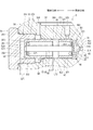
リリーフ弁1は、弁ハウジング30、弁部材40、「付勢部材」としてのスプリング45、「付勢力調整部材」としてのアジャスティングパイプ50、「規制部材」としてのストッパ60などを有する。なお、図1には、弁部材40が有する傾斜面431が弁ハウジング30が有する「弁座」としての内壁311に当接するよう移動する方向を「閉弁方向」とし、傾斜面431が内壁311から離間するよう移動する方向を「開弁方向」として図示する。
Next, the configuration of the relief valve 1 will be described in detail with reference to FIG.
The relief valve 1 includes a valve housing 30, a valve member 40, a spring 45 as an “urging member”, an adjusting pipe 50 as an “urging force adjusting member”, a stopper 60 as a “regulating member”, and the like. In FIG. 1, the direction in which the inclined surface 431 of the valve member 40 moves so as to contact the inner wall 311 as the “valve seat” of the valve housing 30 is referred to as “valve closing direction”, and the inclined surface 431 is the inner wall 311. The direction of movement away from the valve is shown as the “valve opening direction”.

弁ハウジング30は、例えば、ステンレスなどの金属から形成されている。弁ハウジング30は、「弁座部材」としての弁座部31、第一筒部32、第二筒部33、「第二弁ボディ」としてのプラグ34などから形成されている。本実施形態では、弁座部31、第一筒部32及び第二筒部33は、高圧ポンプ20のポンプハウジング21と一体に略有底筒状に形成されている。第一筒部32、第二筒部33及びプラグ34は、特許請求の範囲に記載の「弁ボディ」に相当する。また、第一筒部32及び第二筒部33は、特許請求の範囲に記載の「第一弁ボディ」に相当する。   The valve housing 30 is formed from metal, such as stainless steel, for example. The valve housing 30 includes a valve seat portion 31 as a “valve seat member”, a first tube portion 32, a second tube portion 33, a plug 34 as a “second valve body”, and the like. In the present embodiment, the valve seat portion 31, the first cylindrical portion 32, and the second cylindrical portion 33 are formed in a substantially bottomed cylindrical shape integrally with the pump housing 21 of the high-pressure pump 20. The 1st cylinder part 32, the 2nd cylinder part 33, and the plug 34 are corresponded to the "valve body" as described in a claim. Moreover, the 1st cylinder part 32 and the 2nd cylinder part 33 are corresponded to the "1st valve body" as described in a claim.

弁座部31は、弁ハウジング30の内部空間300を形成する第一筒部32の第二筒部33とは反対側に設けられている。
弁座部31は、吐出通路214と連通する通孔310を有する。通孔310を形成する弁座部31の吐出通路214とは反対側の内壁311は、吐出通路214側から内部空間300側に向かうにつれて内径が大きくなるよう形成されている
The valve seat portion 31 is provided on the side opposite to the second cylinder portion 33 of the first cylinder portion 32 that forms the internal space 300 of the valve housing 30.
The valve seat portion 31 has a through hole 310 that communicates with the discharge passage 214. The inner wall 311 on the opposite side of the discharge passage 214 of the valve seat portion 31 forming the through hole 310 is formed so that the inner diameter increases from the discharge passage 214 side toward the inner space 300 side.

第一筒部32は、弁部材40を往復移動可能に収容する略筒状の部位である。第一筒部32は、内壁321が弁部材40の径方向外側の外壁421と摺動可能に形成されている。第一筒部32は、内壁321の弁部材40が摺動可能な部位に内部空間300と燃料室211とを連通する連通路320を有する。第一筒部32は、弁座部31が設けられる側とは反対側の内部にアジャスティングパイプ50が圧入されている。   The 1st cylinder part 32 is a substantially cylindrical site | part which accommodates the valve member 40 so that a reciprocation is possible. The first cylindrical portion 32 is formed such that the inner wall 321 is slidable with the outer wall 421 on the radially outer side of the valve member 40. The first cylindrical portion 32 has a communication path 320 that communicates the internal space 300 and the fuel chamber 211 at a portion where the valve member 40 of the inner wall 321 can slide. As for the 1st cylinder part 32, the adjusting pipe 50 is press-fitted in the inside on the opposite side to the side in which the valve seat part 31 is provided.

第二筒部33は、第一筒部32の弁座部31とは反対側に設けられる筒状の部位である。第二筒部33は、内径が第一筒部32に比べ大きくなるよう形成されている。第二筒部33の内壁331にはねじ溝が形成されている。第二筒部33は、第一筒部32側に連通路320とは別異に内部空間300と燃料室211とを連通する連通路330を有する。   The second cylindrical portion 33 is a cylindrical portion provided on the opposite side of the first cylindrical portion 32 from the valve seat portion 31. The second cylindrical portion 33 is formed so that the inner diameter is larger than that of the first cylindrical portion 32. A thread groove is formed in the inner wall 331 of the second cylindrical portion 33. The second cylinder part 33 has a communication path 330 that communicates the internal space 300 and the fuel chamber 211 on the first cylinder part 32 side, unlike the communication path 320.

プラグ34は、弁座部31、第一筒部32及び第二筒部33とともに内部空間300を形成する。プラグ34は、本体部341、小内径部342、大内径部343などを有する。本体部341、小内径部342及び大内径部343は、一体に形成されている。
本体部341は、断面が略六角形の柱状の部位である。本体部341は、第二筒部33の第一筒部32が設けられる側とは反対側の開口を塞ぐよう設けられる。
小内径部342は、本体部341の内壁311側に設けられる略筒状の部位である。小内径部342は、内側にストッパ60の端部を挿入可能なストッパ挿入空間344を有する。
大内径部343は、小内径部342の内壁311側に設けられる略筒状の部位である。大内径部343は、外径が第二筒部33の内径と略同等となるよう形成されている。大内径部343の外壁345には、ねじ溝が形成されている。当該ねじ溝は、第二筒部33の内壁331に形成されているねじ溝と係合可能なねじ溝である。これにより、プラグ34は、第二筒部33とねじ結合している。大内径部343は、内側にアジャスティングパイプ50の端部を挿入可能なパイプ挿入空間346を有する。パイプ挿入空間346は、プラグ34の内壁311側でストッパ挿入空間344と内部空間300とを連通している。
The plug 34 forms an internal space 300 together with the valve seat portion 31, the first cylinder portion 32, and the second cylinder portion 33. The plug 34 has a main body portion 341, a small inner diameter portion 342, a large inner diameter portion 343, and the like. The main body portion 341, the small inner diameter portion 342 and the large inner diameter portion 343 are integrally formed.
The main body 341 is a columnar part having a substantially hexagonal cross section. The main body part 341 is provided so as to close the opening of the second cylinder part 33 on the side opposite to the side where the first cylinder part 32 is provided.
The small inner diameter portion 342 is a substantially cylindrical portion provided on the inner wall 311 side of the main body portion 341. The small inner diameter portion 342 has a stopper insertion space 344 into which the end of the stopper 60 can be inserted.
The large inner diameter portion 343 is a substantially cylindrical portion provided on the inner wall 311 side of the small inner diameter portion 342. The large inner diameter portion 343 is formed so that the outer diameter is substantially equal to the inner diameter of the second cylindrical portion 33. A thread groove is formed in the outer wall 345 of the large inner diameter portion 343. The thread groove is a thread groove that can be engaged with the thread groove formed on the inner wall 331 of the second cylindrical portion 33. Thereby, the plug 34 is screw-coupled to the second cylindrical portion 33. The large inner diameter portion 343 has a pipe insertion space 346 into which the end of the adjusting pipe 50 can be inserted. The pipe insertion space 346 communicates the stopper insertion space 344 and the internal space 300 on the inner wall 311 side of the plug 34.

弁部材40は、例えば、ステンレスなどの金属から有底筒状に形成されている。弁部材40は、第一筒部32内に往復移動可能に収容されている。弁部材40は、底部41、摺動部42、シール部43などから形成されている。   The valve member 40 is formed in a bottomed cylindrical shape from a metal such as stainless steel, for example. The valve member 40 is accommodated in the first cylinder portion 32 so as to be able to reciprocate. The valve member 40 is formed of a bottom portion 41, a sliding portion 42, a seal portion 43, and the like.

底部41は、弁部材40が往復移動する方向、すなわち、リリーフ弁1の中心軸CA1の方向に対して略垂直に形成されている円板状の部位である。底部41は、外径が第一筒部32の内径に比べ小さくなるよう形成されている。底部41の一方の面411にはシール部43が設けられている。一方の面411は、リリーフ弁1が開弁しているとき、吐出通路214の流体の圧力が作用する受圧面となる。底部41の他方の面412にはスプリング45の一端が当接している。   The bottom 41 is a disc-shaped portion formed substantially perpendicular to the direction in which the valve member 40 reciprocates, that is, the direction of the central axis CA1 of the relief valve 1. The bottom 41 is formed so that the outer diameter is smaller than the inner diameter of the first cylinder part 32. A seal portion 43 is provided on one surface 411 of the bottom portion 41. One surface 411 is a pressure receiving surface on which the pressure of the fluid in the discharge passage 214 acts when the relief valve 1 is open. One end of the spring 45 is in contact with the other surface 412 of the bottom 41.

摺動部42は、底部41の他方の面412側に設けられる略筒状の部位である。摺動部42は、径方向外側の外壁421が第一筒部32の内壁321に摺動可能である。これにより、弁部材40は、弁ハウジング30によって往復移動が案内される。   The sliding portion 42 is a substantially cylindrical portion provided on the other surface 412 side of the bottom portion 41. In the sliding portion 42, the radially outer outer wall 421 can slide on the inner wall 321 of the first cylindrical portion 32. As a result, the valve member 40 is guided to reciprocate by the valve housing 30.

シール部43は、底部41の一方の面411側に設けられる。シール部43は、一方の面411から弁座部31に向かって突出するよう形成されている。シール部43は、底部41とは反対側の先端の角部に中心軸CA1に対して傾斜するよう形成されている傾斜面431を有する。   The seal portion 43 is provided on the one surface 411 side of the bottom portion 41. The seal portion 43 is formed so as to protrude from the one surface 411 toward the valve seat portion 31. The seal part 43 has an inclined surface 431 formed to be inclined with respect to the central axis CA1 at the corner of the tip opposite to the bottom part 41.

傾斜面431は、弁座部31の内壁311に当接可能に形成されている。傾斜面431と内壁311とが当接すると吐出通路214と内部空間300との間の燃料の流れが規制される。傾斜面431と内壁311とが離間すると吐出通路214と内部空間300との間の燃料の流れを許容する。弁座部31側の先端面432は、リリーフ弁1が閉弁しているとき、吐出通路214の流体の圧力が作用する受圧面となる。   The inclined surface 431 is formed so as to be able to contact the inner wall 311 of the valve seat portion 31. When the inclined surface 431 and the inner wall 311 come into contact with each other, the flow of fuel between the discharge passage 214 and the internal space 300 is restricted. When the inclined surface 431 and the inner wall 311 are separated from each other, the fuel flow between the discharge passage 214 and the internal space 300 is allowed. The distal end surface 432 on the valve seat portion 31 side becomes a pressure receiving surface on which the fluid pressure of the discharge passage 214 acts when the relief valve 1 is closed.

スプリング45は、例えば、コイルスプリングである。スプリング45は、弁部材40及びアジャスティングパイプ50の内部に収容されている。一端が弁部材40の他方の面412に当接し、他端がアジャスティングパイプ50に当接している。スプリング45は、傾斜面431と内壁311とが当接するよう弁部材40を付勢する。   The spring 45 is, for example, a coil spring. The spring 45 is accommodated inside the valve member 40 and the adjusting pipe 50. One end is in contact with the other surface 412 of the valve member 40 and the other end is in contact with the adjusting pipe 50. The spring 45 biases the valve member 40 so that the inclined surface 431 and the inner wall 311 come into contact with each other.

アジャスティングパイプ50は、例えば、ステンレスなどの金属から有底筒状に形成され、弁部材40の通孔310とは反対側に設けられている。アジャスティングパイプ50は、筒部51、底部52などを有している。筒部51及び底部52は、一体に形成されている。
筒部51は、外径が第一筒部32の内径と同等、または、第一筒部32の内径よりやや大きくなるよう形成されている筒状の部位である。筒部51は、弁部材40側及び弁部材40と反対側に開口を有する。筒部51は、例えば、溶接または圧入などにより第一筒部32の内側に固定されている。
The adjusting pipe 50 is formed, for example, from a metal such as stainless steel into a bottomed cylindrical shape, and is provided on the side opposite to the through hole 310 of the valve member 40. The adjusting pipe 50 has a cylindrical portion 51, a bottom portion 52, and the like. The cylinder part 51 and the bottom part 52 are integrally formed.
The cylindrical part 51 is a cylindrical part formed so that the outer diameter is equal to the inner diameter of the first cylindrical part 32 or slightly larger than the inner diameter of the first cylindrical part 32. The cylinder part 51 has openings on the valve member 40 side and the opposite side to the valve member 40. The cylinder part 51 is fixed inside the first cylinder part 32 by, for example, welding or press fitting.

底部52は、筒部51の弁部材40とは反対側の開口を塞ぐよう設けられている。底部52及び筒部51の一部は、プラグ34のパイプ挿入空間346に挿入されている。このとき、底部52及び筒部51の一部とプラグ34との間には隙間が形成されている。底部52は、中央に筒部51の内部と外部とを連通する孔520を有している。底部52の弁部材40側の底面521には、スプリング45の他端が当接している。これにより、アジャスティングパイプ50の第一筒部32に対する固定位置を変更すると、スプリング45の付勢力が調整される。   The bottom portion 52 is provided so as to close the opening of the cylinder portion 51 on the side opposite to the valve member 40. A part of the bottom portion 52 and the cylindrical portion 51 is inserted into the pipe insertion space 346 of the plug 34. At this time, a gap is formed between the bottom portion 52 and part of the cylindrical portion 51 and the plug 34. The bottom portion 52 has a hole 520 that communicates the inside and the outside of the cylindrical portion 51 at the center. The other end of the spring 45 is in contact with the bottom surface 521 of the bottom 52 on the valve member 40 side. Accordingly, when the fixing position of the adjusting pipe 50 with respect to the first tube portion 32 is changed, the urging force of the spring 45 is adjusted.

ストッパ60は、弁ハウジング30内においてプラグ34側から弁部材40の方向に延びるよう形成されている。ストッパ60は、アジャスティングパイプ50とは別体に設けられ、「ボディ側固定部」としての固定部61、「ボディ側当接部」としてのロッド部62などを有する。固定部61とロッド部62とは一体に形成されている。   The stopper 60 is formed in the valve housing 30 so as to extend from the plug 34 side toward the valve member 40. The stopper 60 is provided separately from the adjusting pipe 50 and includes a fixing portion 61 as a “body-side fixing portion”, a rod portion 62 as a “body-side abutting portion”, and the like. The fixed part 61 and the rod part 62 are formed integrally.

固定部61は、略円柱状に形成されている。固定部61は、プラグ34のストッパ挿入空間344に圧入され固定されている。   The fixed part 61 is formed in a substantially cylindrical shape. The fixing portion 61 is press-fitted into the stopper insertion space 344 of the plug 34 and fixed.

ロッド部62は、固定部61の弁部材40側の端面611に設けられている。ロッド部62は、固定部61から弁部材40の方向に延びるよう形成されている略棒状の部位である。ロッド部62は、外径が固定部61の外径に比べ小さくなるよう形成され、アジャスティングパイプ50の孔520に挿通されている。ロッド部62の内壁311側の端面621は、弁部材40の他方の面412の近傍に位置している。
具体的には、シール部43の傾斜面431と弁座部31の内壁311とが当接しているとき、端面621と弁部材40の他方の面412との間の距離L11は、弁部材40のアジャスティングパイプ50側の端面422とアジャスティングパイプ50の弁部材40側の端面511との間の距離L12に比べ短い。また、連通路320の内部空間300側の開口302を形成する内壁321のうち内壁311側の縁部を縁部303とし、弁部材40の外壁421のうち内壁321に摺動している外壁421の内壁311側の縁部を縁部401とすると、距離L11は、内壁311と傾斜面431とが当接しているときの縁部303と縁部401との距離L13に比べ長い。
The rod portion 62 is provided on the end surface 611 of the fixed portion 61 on the valve member 40 side. The rod portion 62 is a substantially rod-shaped portion formed so as to extend from the fixed portion 61 toward the valve member 40. The rod part 62 is formed so that the outer diameter is smaller than the outer diameter of the fixed part 61, and is inserted through the hole 520 of the adjusting pipe 50. An end surface 621 on the inner wall 311 side of the rod portion 62 is located in the vicinity of the other surface 412 of the valve member 40.
Specifically, when the inclined surface 431 of the seal portion 43 and the inner wall 311 of the valve seat portion 31 are in contact, the distance L11 between the end surface 621 and the other surface 412 of the valve member 40 is the valve member 40. The distance L12 between the end surface 422 on the adjusting pipe 50 side and the end surface 511 on the valve member 40 side of the adjusting pipe 50 is shorter. Further, an edge on the inner wall 311 side of the inner wall 321 that forms the opening 302 on the inner space 300 side of the communication path 320 is an edge 303, and an outer wall 421 that slides on the inner wall 321 of the outer wall 421 of the valve member 40. When the edge on the inner wall 311 side is the edge 401, the distance L11 is longer than the distance L13 between the edge 303 and the edge 401 when the inner wall 311 and the inclined surface 431 are in contact with each other.

次に、本実施形態の高圧ポンプ20の作動について、図2に基づき説明する。
「吸入工程」
駆動部24への電力の供給が停止されているとき、吸入弁22の弁部材222は、駆動部24によって加圧室213側へ付勢されている。これにより、弁部材222は、弁座221から離間しており、吸入弁22は開弁している。この状態で、プランジャ25がカム18側に移動すると、加圧室213の容積が増大し、吸入通路212の燃料は、加圧室213に吸入される。
Next, the operation of the high-pressure pump 20 of this embodiment will be described with reference to FIG.
"Inhalation process"
When the supply of power to the drive unit 24 is stopped, the valve member 222 of the suction valve 22 is biased toward the pressurizing chamber 213 by the drive unit 24. Thus, the valve member 222 is separated from the valve seat 221 and the intake valve 22 is opened. In this state, when the plunger 25 moves to the cam 18 side, the volume of the pressurizing chamber 213 increases, and the fuel in the suction passage 212 is sucked into the pressurizing chamber 213.

「調量工程」
吸入弁22が開弁した状態でプランジャ25がカム18とは反対側に移動すると、加圧室213の容積が減少し、加圧室213の燃料は、吸入通路212に戻される。調量工程の途中において駆動部24に電力を供給すると、吸入弁22は閉弁する。この吸入弁22を閉弁するタイミングによって加圧室213から吸入通路212に戻される燃料の量が調整され、加圧室213で加圧される燃料の量が決定される。
“Weighing process”
When the plunger 25 moves to the opposite side of the cam 18 with the intake valve 22 opened, the volume of the pressurizing chamber 213 decreases and the fuel in the pressurizing chamber 213 is returned to the intake passage 212. When power is supplied to the drive unit 24 during the metering process, the suction valve 22 is closed. The amount of fuel returned from the pressurizing chamber 213 to the suction passage 212 is adjusted by the timing of closing the suction valve 22, and the amount of fuel pressurized in the pressurizing chamber 213 is determined.

「加圧工程」
吸入弁22が閉弁した状態でプランジャ25がカム18とは反対側にさらに移動すると、加圧室213の容積が減少し、加圧室213の燃料は、加圧される。加圧室213の燃料の圧力が吐出弁23の開弁圧以上になると、吐出弁23が開弁し、燃料が加圧室213から吐出通路214に吐出される。
"Pressurization process"
When the plunger 25 further moves to the side opposite to the cam 18 with the intake valve 22 closed, the volume of the pressurizing chamber 213 decreases and the fuel in the pressurizing chamber 213 is pressurized. When the pressure of the fuel in the pressurizing chamber 213 becomes equal to or higher than the opening pressure of the discharge valve 23, the discharge valve 23 is opened and the fuel is discharged from the pressurizing chamber 213 to the discharge passage 214.

駆動部24への電力の供給が停止され、プランジャ25がカム18側に移動すると、吸入弁22は再び開弁する。これにより、燃料を加圧する加圧工程が終了し、吸入通路212から加圧室213に燃料が吸入される吸入工程が再開する。   When the supply of electric power to the drive unit 24 is stopped and the plunger 25 moves to the cam 18 side, the intake valve 22 is opened again. As a result, the pressurization process for pressurizing the fuel is completed, and the suction process in which the fuel is sucked into the pressurization chamber 213 from the suction passage 212 is resumed.

上記の「吸入工程」、「調量工程」、「加圧工程」を繰り返すことにより、高圧ポンプ20は、吸入した燃料タンク12内の燃料を加圧及び吐出し、燃料レール15に供給する。高圧ポンプ20から燃料レール15への燃料の供給量は、駆動部24への電力の供給タイミングなどを制御することによって調節される。   By repeating the above “suction process”, “metering process”, and “pressurization process”, the high-pressure pump 20 pressurizes and discharges the fuel in the fuel tank 12 and supplies it to the fuel rail 15. The amount of fuel supplied from the high-pressure pump 20 to the fuel rail 15 is adjusted by controlling the supply timing of power to the drive unit 24 and the like.

例えば、駆動部24への電力の供給が停止された状態のままプランジャ25の往復移動が所定期間継続すると、吸入弁22は開弁状態を維持しているため、加圧室213での燃料の加圧は行われず、燃料は高圧ポンプ20から燃料レール15に供給されない。また、弁部材222の固着など何らかの原因により吸入弁22が開弁状態を維持している場合、加圧室213での燃料の加圧は行われず、燃料は高圧ポンプ20から燃料レール15に供給されない。また、弁部材222の固着など何らかの原因により吸入弁22が閉弁状態を維持している場合、加圧室213に燃料は吸入されなくなるため、燃料の加圧は行われず、燃料は高圧ポンプ20から燃料レール15に供給されない。   For example, if the reciprocating movement of the plunger 25 continues for a predetermined period while the supply of electric power to the drive unit 24 is stopped, the intake valve 22 is kept open, so that the fuel in the pressurizing chamber 213 No pressurization is performed and fuel is not supplied from the high pressure pump 20 to the fuel rail 15. Further, when the suction valve 22 is kept open for some reason, such as the sticking of the valve member 222, fuel is not pressurized in the pressurizing chamber 213, and fuel is supplied from the high-pressure pump 20 to the fuel rail 15. Not. Further, when the suction valve 22 is kept closed due to some cause such as the sticking of the valve member 222, the fuel is not sucked into the pressurizing chamber 213, so that the fuel is not pressurized and the fuel is not pumped. Is not supplied to the fuel rail 15.

一方、例えば、駆動部24への電力の供給が所定期間継続すると、吸入弁22は閉弁状態を維持するため、燃料は、加圧室213で加圧され、高圧ポンプ20から燃料レール15に供給され、吐出通路214、配管14、燃料レール15内の燃料の圧力が増大していく。また、連続通電や駆動部の故障などによって吸入弁22の弁部材222が加圧室213の圧力に応じて駆動すると、加圧は継続される。   On the other hand, for example, when the supply of electric power to the drive unit 24 continues for a predetermined period, the intake valve 22 is maintained in the closed state, so that the fuel is pressurized in the pressurizing chamber 213 and is supplied from the high pressure pump 20 to the fuel rail 15. The pressure of the fuel in the discharge passage 214, the pipe 14, and the fuel rail 15 increases. Further, when the valve member 222 of the suction valve 22 is driven according to the pressure in the pressurizing chamber 213 due to continuous energization or a failure of the drive unit, pressurization is continued.

次に、本実施形態のリリーフ弁1の作動について図1に基づき説明する。
吐出通路214の燃料の圧力が開弁圧以上になると、傾斜面431が内壁311から離間する。傾斜面431が内壁311から離間すると、通孔310を介して弁座部31、第一筒部32、及び、底部41によって形成される内部空間300の中間室301に吐出通路214の燃料が流入し、中間室301の燃料の圧力が増大する。これにより、弁部材40は、弁座部31から離れる方向に移動する。
Next, the operation of the relief valve 1 of the present embodiment will be described with reference to FIG.
When the fuel pressure in the discharge passage 214 becomes equal to or higher than the valve opening pressure, the inclined surface 431 is separated from the inner wall 311. When the inclined surface 431 is separated from the inner wall 311, the fuel in the discharge passage 214 flows into the intermediate chamber 301 of the internal space 300 formed by the valve seat portion 31, the first cylindrical portion 32, and the bottom portion 41 through the through hole 310. As a result, the fuel pressure in the intermediate chamber 301 increases. Thereby, the valve member 40 moves in a direction away from the valve seat portion 31.

弁部材40が弁座部31から離れる方向にさらに移動すると、中間室301と連通路320とが連通する。これにより、中間室301の燃料は、連通路320を介して燃料室211に向かう。このとき、弁座部31から離れる方向に移動する弁部材40は、ストッパ60が有する端面621に当接し、弁座部31から離れる方向への移動が規制される。このとき、弁部材40とアジャスティングパイプ50とは離間したままとなっている。   When the valve member 40 further moves in the direction away from the valve seat portion 31, the intermediate chamber 301 and the communication passage 320 communicate with each other. Thereby, the fuel in the intermediate chamber 301 is directed to the fuel chamber 211 via the communication path 320. At this time, the valve member 40 that moves in the direction away from the valve seat 31 abuts on the end surface 621 of the stopper 60, and movement in the direction away from the valve seat 31 is restricted. At this time, the valve member 40 and the adjusting pipe 50 remain separated.

また、中間室301から弁部材40の外壁421と第一筒部32の内壁321との間を通って弁部材40のプラグ34側に流入する燃料は、連通路330を通って燃料室211に流れる。   Further, the fuel flowing from the intermediate chamber 301 to the plug 34 side of the valve member 40 through the space between the outer wall 421 of the valve member 40 and the inner wall 321 of the first cylindrical portion 32 passes through the communication passage 330 to the fuel chamber 211. Flowing.

中間室301の燃料の圧力が低減すると、弁部材40は、スプリング45の付勢力によって弁座部31の方向に移動する。弁部材40が閉弁方向に移動すると、中間室301と連通路320とが遮断されるとともに、傾斜面431と内壁311とが当接する。これにより、リリーフ弁1は、閉弁する。   When the pressure of the fuel in the intermediate chamber 301 is reduced, the valve member 40 moves in the direction of the valve seat portion 31 by the biasing force of the spring 45. When the valve member 40 moves in the valve closing direction, the intermediate chamber 301 and the communication path 320 are blocked, and the inclined surface 431 and the inner wall 311 come into contact with each other. Thereby, the relief valve 1 is closed.

(a)リリーフ弁1では、弁部材40が開弁方向に移動するとき弁部材40に当接し弁部材40の開弁方向への移動を規制するストッパ60がアジャスティングパイプ50と別体に設けられている。これにより、弁部材40のリフト量を弁ハウジング30に対するストッパ60の位置によって調整することができるため、スプリング45の付勢力の調整とは無関係に弁部材40のリフト量を正確に規定することができる。したがって、リリーフ弁1では、弁部材40のリフト量のばらつきを低減しつつ作動時の信頼性を向上することができる。   (A) In the relief valve 1, a stopper 60 that is in contact with the valve member 40 when the valve member 40 moves in the valve opening direction and restricts the movement of the valve member 40 in the valve opening direction is provided separately from the adjusting pipe 50. It has been. As a result, the lift amount of the valve member 40 can be adjusted by the position of the stopper 60 with respect to the valve housing 30, so that the lift amount of the valve member 40 can be accurately defined regardless of the adjustment of the biasing force of the spring 45. it can. Therefore, in the relief valve 1, the reliability during operation can be improved while reducing variations in the lift amount of the valve member 40.

(b)また、リリーフ弁1では、アジャスティングパイプ50は、スプリング45の付勢力を調整する機能のみを有することとなるため、スプリング45の付勢力を精度良く調整することができる。   (B) In the relief valve 1, the adjusting pipe 50 has only a function of adjusting the urging force of the spring 45, so that the urging force of the spring 45 can be adjusted with high accuracy.

(c)さらに、リリーフ弁1では、図1に示すように、傾斜面431が内壁331に当接しているとき、距離L11は、距離L12に比べ短い。これにより、リリーフ弁1が開弁するとき、弁部材40とアジャスティングパイプ50とが当接しなくなるため、弁部材40との当接によってアジャスティングパイプ50が移動したり破損したりすることを防止できる。したがって、最初に設定したスプリング45の付勢力の変化を防止することができるため、所定の開弁圧で開弁することができる。   (C) Further, in the relief valve 1, as shown in FIG. 1, when the inclined surface 431 is in contact with the inner wall 331, the distance L11 is shorter than the distance L12. Thereby, when the relief valve 1 is opened, the valve member 40 and the adjusting pipe 50 do not come into contact with each other, so that the adjusting pipe 50 is prevented from moving or damaged due to contact with the valve member 40. it can. Therefore, since it is possible to prevent a change in the urging force of the spring 45 set initially, the valve 45 can be opened with a predetermined valve opening pressure.

(d)リリーフ弁1では、ストッパ60は、第二筒部33とねじ結合しているプラグ34に固定されている。これにより、プラグ34と第二筒部33とのねじ結合の位置を調整することによって端面621と他方の面412との間の距離L11を調整することができる。したがって、弁部材40のリフト量のばらつきをさらに低減することができる。   (D) In the relief valve 1, the stopper 60 is fixed to the plug 34 that is screw-coupled to the second cylindrical portion 33. Thereby, the distance L11 between the end surface 621 and the other surface 412 can be adjusted by adjusting the position of the screw connection between the plug 34 and the second cylindrical portion 33. Therefore, the variation in the lift amount of the valve member 40 can be further reduced.

(第二実施形態)
本発明の第二実施形態によるリリーフ弁装置を図3に基づき説明する。第二実施形態では、弁ハウジング及びストッパが第一実施形態と異なる。
(Second embodiment)
A relief valve device according to a second embodiment of the present invention will be described with reference to FIG. In the second embodiment, the valve housing and the stopper are different from the first embodiment.

「リリーフ弁装置」としてのリリーフ弁2は、弁ハウジング30、弁部材40、スプリング45、アジャスティングパイプ50、「規制部材」としてのストッパ65などを有する。なお、図3には、弁部材40の傾斜面431が弁ハウジング30の内壁311に当接するよう移動する方向を「閉弁方向」とし、傾斜面431が内壁311から離間するよう移動する方向を「開弁方向」として図示する。   The relief valve 2 as a “relief valve device” includes a valve housing 30, a valve member 40, a spring 45, an adjusting pipe 50, a stopper 65 as a “regulating member”, and the like. In FIG. 3, a direction in which the inclined surface 431 of the valve member 40 moves so as to contact the inner wall 311 of the valve housing 30 is referred to as a “valve closing direction”, and a direction in which the inclined surface 431 moves away from the inner wall 311 is illustrated. This is illustrated as “valve opening direction”.

弁ハウジング30は、弁座部31、第一筒部32、第二筒部33、「第二弁ボディ」としてのプラグ35などから形成されている。   The valve housing 30 is formed of a valve seat portion 31, a first tube portion 32, a second tube portion 33, a plug 35 as a “second valve body”, and the like.

プラグ35は、第二筒部33の第一筒部32が設けられる側とは反対側の開口に設けられる。プラグ35は、弁座部31、第一筒部32及び第二筒部33とともに内部空間300を形成する。プラグ35は、本体部351、筒部352などを有する。本体部351及び筒部352は、一体に形成されている。
本体部351は、略円板状の部位である。本体部351は、第二筒部33の第一筒部32が設けられる側とは反対側の開口を塞ぐよう設けられる。
筒部352は、本体部351の内壁311側に設けられる略筒状の部位である。筒部352は、外径が第二筒部33の内径と略同等となるよう形成されている。筒部352の外壁353には、ねじ溝が形成されている。当該ねじ溝は、第二筒部33の内壁331に形成されているねじ溝と係合可能なねじ溝である。これにより、プラグ35は、第二筒部33とねじ結合している。筒部352は、内側にアジャスティングパイプ50の端部を挿入可能なパイプ挿入空間354を有する。パイプ挿入空間354を形成する本体部351の「弁ボディの通孔が形成されている側とは反対側の内壁」としての底面356及び筒部352の内壁355とアジャスティングパイプ50の外壁との間には隙間が形成されている。
The plug 35 is provided in an opening on the side opposite to the side where the first cylinder part 32 of the second cylinder part 33 is provided. The plug 35 forms an internal space 300 together with the valve seat part 31, the first cylinder part 32 and the second cylinder part 33. The plug 35 includes a main body portion 351, a cylindrical portion 352, and the like. The main body portion 351 and the cylindrical portion 352 are integrally formed.
The main body 351 is a substantially disk-shaped part. The main body 351 is provided so as to close the opening of the second cylindrical portion 33 on the side opposite to the side where the first cylindrical portion 32 is provided.
The cylindrical part 352 is a substantially cylindrical part provided on the inner wall 311 side of the main body part 351. The cylinder part 352 is formed so that the outer diameter is substantially equal to the inner diameter of the second cylinder part 33. A thread groove is formed in the outer wall 353 of the cylindrical portion 352. The thread groove is a thread groove that can be engaged with the thread groove formed on the inner wall 331 of the second cylindrical portion 33. Thereby, the plug 35 is screw-coupled to the second cylindrical portion 33. The cylindrical portion 352 has a pipe insertion space 354 into which the end of the adjusting pipe 50 can be inserted. The bottom surface 356 as the “inner wall opposite to the side where the valve body passage hole is formed” of the main body portion 351 forming the pipe insertion space 354 and the inner wall 355 of the cylindrical portion 352 and the outer wall of the adjusting pipe 50. A gap is formed between them.

ストッパ65は、弁部材40側からプラグ34の方向に延びるよう形成されている。ストッパ65は、弁部材40及びアジャスティングパイプ50とは別体に設けられ、「弁部材側固定部」としての固定部66、「弁部材側当接部」としてのロッド部67などを有する。固定部66とロッド部67とは一体に形成されている。   The stopper 65 is formed so as to extend in the direction of the plug 34 from the valve member 40 side. The stopper 65 is provided separately from the valve member 40 and the adjusting pipe 50, and includes a fixing portion 66 as a “valve member side fixing portion”, a rod portion 67 as a “valve member side contact portion”, and the like. The fixed portion 66 and the rod portion 67 are formed integrally.

固定部66は、円板状に形成されている。固定部66は、弁部材40の他方の面412に当接している。固定部66の他方の面412と当接する側とは反対側の端面661には、スプリング45の一端が当接している。すなわち、固定部66は、弁部材40の底部41とスプリング45との間に挟み込まれている。   The fixing part 66 is formed in a disk shape. The fixed portion 66 is in contact with the other surface 412 of the valve member 40. One end of the spring 45 is in contact with the end surface 661 opposite to the side in contact with the other surface 412 of the fixed portion 66. That is, the fixed portion 66 is sandwiched between the bottom portion 41 of the valve member 40 and the spring 45.

ロッド部67は、固定部66の端面661に設けられている。ロッド部67は、固定部66からプラグ35の方向に延びるよう形成されている略棒状の部位である。ロッド部67は、外径が固定部66の外径に比べ小さくなるよう形成され、アジャスティングパイプ50の孔520に挿通可能である。ロッド部67のプラグ35側の端面671は、底面356の近傍に位置している。
具体的には、シール部43の傾斜面431と弁座部31の内壁311とが当接しているとき、端面671と底面356との間の距離L21は、弁部材40の端面422とアジャスティングパイプ50の端面511との間の距離L12に比べ短い。これにより、弁部材40が開弁方向に移動するとき、ストッパ65とプラグ35とが当接し弁部材40とアジャスティングパイプ50とは離間した状態を維持する。
The rod portion 67 is provided on the end surface 661 of the fixed portion 66. The rod portion 67 is a substantially rod-shaped portion formed so as to extend from the fixed portion 66 in the direction of the plug 35. The rod portion 67 is formed so that the outer diameter is smaller than the outer diameter of the fixed portion 66 and can be inserted into the hole 520 of the adjusting pipe 50. An end surface 671 on the plug 35 side of the rod portion 67 is located in the vicinity of the bottom surface 356.
Specifically, when the inclined surface 431 of the seal portion 43 and the inner wall 311 of the valve seat portion 31 are in contact, the distance L21 between the end surface 671 and the bottom surface 356 is adjusted with the end surface 422 of the valve member 40. It is shorter than the distance L12 between the end surface 511 of the pipe 50. Thereby, when the valve member 40 moves in the valve opening direction, the stopper 65 and the plug 35 are brought into contact with each other, and the valve member 40 and the adjusting pipe 50 are maintained in a separated state.

リリーフ弁2では、弁部材40が開弁方向に移動するときプラグ35に当接し弁部材40の開弁方向への移動を規制するストッパ65がアジャスティングパイプ50と別体に設けられている。これにより、リリーフ弁2は、第一実施形態の効果(a)〜(c)を奏する。
また、プラグ35は、第二筒部33とねじ結合し、かつ、アジャスティングパイプ50との間に隙間を形成している。これにより、スプリング45の付勢力の調整に影響を与えることなく、距離L21を変更することができる。したがって、リリーフ弁2は、第一実施形態の効果(d)を奏する。
In the relief valve 2, a stopper 65 is provided separately from the adjusting pipe 50 so as to come into contact with the plug 35 and restrict the movement of the valve member 40 in the valve opening direction when the valve member 40 moves in the valve opening direction. Thereby, the relief valve 2 has the effects (a) to (c) of the first embodiment.
Further, the plug 35 is screw-coupled to the second cylinder portion 33 and forms a gap between the plug 35 and the adjusting pipe 50. Thus, the distance L21 can be changed without affecting the adjustment of the biasing force of the spring 45. Therefore, the relief valve 2 has the effect (d) of the first embodiment.

(第三実施形態)
本発明の第三実施形態によるリリーフ弁装置を図4に基づき説明する。第三実施形態では、規制部材が第一実施形態と異なる。
(Third embodiment)
A relief valve device according to a third embodiment of the present invention will be described with reference to FIG. In 3rd embodiment, a control member differs from 1st embodiment.

「リリーフ弁装置」としてのリリーフ弁3は、プラグ35を有する弁ハウジング30、弁部材40、スプリング45、アジャスティングパイプ50、「規制部材」としてのストッパ70などを有する。なお、図4には、弁部材40の傾斜面431が弁ハウジング30の内壁311に当接するよう移動する方向を「閉弁方向」とし、傾斜面431が内壁311から離間するよう移動する方向を「開弁方向」として図示する。   The relief valve 3 as a “relief valve device” includes a valve housing 30 having a plug 35, a valve member 40, a spring 45, an adjusting pipe 50, a stopper 70 as a “regulating member”, and the like. In FIG. 4, the direction in which the inclined surface 431 of the valve member 40 moves so as to contact the inner wall 311 of the valve housing 30 is referred to as a “valve closing direction”, and the direction in which the inclined surface 431 moves away from the inner wall 311 is illustrated. This is illustrated as “valve opening direction”.

ストッパ70は、摺動部42の径方向外側の外壁421に設けられている。具体的には、ストッパ70は、外壁421に形成されている内側溝423に嵌合している。ストッパ70は、略C字状に形成され、径方向外側に広がる付勢力を有する。
第一筒部32のストッパ70に対応する位置には外側溝322が形成されている。外側溝322には、ストッパ70の径方向外側の端部がリリーフ弁3の中心軸CA3方向に往復移動可能に収容されている。
The stopper 70 is provided on the outer wall 421 on the radially outer side of the sliding portion 42. Specifically, the stopper 70 is fitted in an inner groove 423 formed in the outer wall 421. The stopper 70 is formed in a substantially C shape and has a biasing force that spreads outward in the radial direction.
An outer groove 322 is formed at a position corresponding to the stopper 70 of the first cylindrical portion 32. The outer groove 322 accommodates the radially outer end of the stopper 70 so as to be capable of reciprocating in the direction of the central axis CA3 of the relief valve 3.

外側溝322を形成する内壁のうち内壁311側の内壁323は、内壁311と傾斜面431とが当接しているとき、ストッパ70の内壁311側の端面701に当接しない程度の位置に形成されている。また、外側溝322を形成する内壁のうち内壁311とは反対側の内壁324は、ストッパ70の内壁311とは反対側の端面702と内壁324とが当接するとき、弁部材40の端面422とアジャスティングパイプ50の端面511との間に隙間が形成される程度の位置に形成されている。   Of the inner walls forming the outer groove 322, the inner wall 323 on the inner wall 311 side is formed at a position that does not contact the end surface 701 on the inner wall 311 side of the stopper 70 when the inner wall 311 and the inclined surface 431 are in contact with each other. ing. Further, the inner wall 324 opposite to the inner wall 311 among the inner walls forming the outer groove 322 is in contact with the end surface 422 of the valve member 40 when the end surface 702 opposite to the inner wall 311 of the stopper 70 and the inner wall 324 come into contact with each other. A gap is formed between the adjusting pipe 50 and the end face 511 of the adjusting pipe 50.

本実施形態では、図4に示すように、シール部43の傾斜面431と弁座部31の内壁311とが当接しているとき、ストッパ70の端面701と内壁323とは当接している。このとき、ストッパ70の端面702と外側溝322の内壁324との間の距離L31は、弁部材40のアジャスティングパイプ50側の端面422とアジャスティングパイプ50の弁部材40側の端面511との間の距離L12に比べ短い。   In the present embodiment, as shown in FIG. 4, when the inclined surface 431 of the seal portion 43 and the inner wall 311 of the valve seat portion 31 are in contact, the end surface 701 of the stopper 70 and the inner wall 323 are in contact. At this time, the distance L31 between the end surface 702 of the stopper 70 and the inner wall 324 of the outer groove 322 is between the end surface 422 of the valve member 40 on the adjusting pipe 50 side and the end surface 511 of the adjusting pipe 50 on the valve member 40 side. Shorter than the distance L12.

リリーフ弁3を組み立てるとき、ストッパ70は、弁部材40の外壁421に設けられている状態で第一筒部32の内部に挿入される。第一筒部32の内部に弁部材40とともに入るストッパ70は、内壁321に摺動しつつ内壁311側に進み、外側溝322において自身が持っている付勢力によって径外方向に広がる。これにより、ストッパ70は、内側溝423に嵌合しつつ外側溝322を往復移動可能となる。   When assembling the relief valve 3, the stopper 70 is inserted into the first cylindrical portion 32 in a state of being provided on the outer wall 421 of the valve member 40. The stopper 70 that enters the first cylindrical portion 32 together with the valve member 40 advances toward the inner wall 311 while sliding on the inner wall 321, and spreads radially outward by the urging force of the outer groove 322. As a result, the stopper 70 can reciprocate in the outer groove 322 while being fitted to the inner groove 423.

リリーフ弁3では、弁部材40が開弁方向に移動するとき弁ハウジング30に当接し弁部材40の開弁方向への移動を規制するストッパ70がアジャスティングパイプ50と別体に設けられている。これにより、リリーフ弁3が開弁するとき、開弁方向に弁部材40が移動してもストッパ70と内壁324とが当接し、弁部材40とアジャスティングパイプ50との当接を防止することができる。したがって、リリーフ弁3は、第一実施形態の効果(a)〜(c)を奏する。   In the relief valve 3, a stopper 70 that is in contact with the valve housing 30 and restricts the movement of the valve member 40 in the valve opening direction when the valve member 40 moves in the valve opening direction is provided separately from the adjusting pipe 50. . Thereby, when the relief valve 3 is opened, even if the valve member 40 moves in the valve opening direction, the stopper 70 and the inner wall 324 come into contact with each other, and contact between the valve member 40 and the adjusting pipe 50 is prevented. Can do. Therefore, the relief valve 3 has the effects (a) to (c) of the first embodiment.

(第四実施形態)
本発明の第四実施形態によるリリーフ弁装置を図5に基づき説明する。第四実施形態では、規制部材が第一実施形態と異なる。
(Fourth embodiment)
A relief valve device according to a fourth embodiment of the present invention will be described with reference to FIG. In 4th embodiment, a control member differs from 1st embodiment.

「リリーフ弁装置」としてのリリーフ弁4は、プラグ35を有する弁ハウジング30、弁部材40、スプリング45、アジャスティングパイプ50、「規制部材」としてのストッパ75などを有する。なお、図5には、弁部材40の傾斜面431が弁ハウジング30の内壁311に当接するよう移動する方向を「閉弁方向」とし、傾斜面431が内壁311から離間するよう移動する方向を「開弁方向」として図示する。   The relief valve 4 as a “relief valve device” includes a valve housing 30 having a plug 35, a valve member 40, a spring 45, an adjusting pipe 50, a stopper 75 as a “regulating member”, and the like. In FIG. 5, a direction in which the inclined surface 431 of the valve member 40 moves so as to contact the inner wall 311 of the valve housing 30 is referred to as a “valve closing direction”, and a direction in which the inclined surface 431 moves away from the inner wall 311 is illustrated. This is illustrated as “valve opening direction”.

ストッパ75は、第一筒部32の内壁321に固定されている。具体的には、弁部材40とアジャスティングパイプ50との間の内壁321に形成されている溝325に嵌合している。ストッパ75は、略C字状に形成され、径方向外側に広がる付勢力を有する。   The stopper 75 is fixed to the inner wall 321 of the first cylindrical portion 32. Specifically, it fits into a groove 325 formed in the inner wall 321 between the valve member 40 and the adjusting pipe 50. The stopper 75 is formed in a substantially C shape and has a biasing force that spreads outward in the radial direction.

リリーフ弁4を組み立てるとき、ストッパ75は、弁部材40を第一筒部32の内部に挿入した後、第一筒部32の内部に挿入される。第一筒部32の内部に入ったストッパ70は、内壁321を摺動しつつ内壁311側に進み、溝325において自身の付勢力によって径外方向に広がる。これにより、ストッパ75は、溝325に嵌合し第一筒部32に対して固定される。   When the relief valve 4 is assembled, the stopper 75 is inserted into the first cylinder part 32 after the valve member 40 is inserted into the first cylinder part 32. The stopper 70 that has entered the inside of the first cylindrical portion 32 advances toward the inner wall 311 while sliding on the inner wall 321, and spreads radially outward in the groove 325 by its urging force. Accordingly, the stopper 75 is fitted into the groove 325 and fixed to the first cylindrical portion 32.

リリーフ弁4では、弁部材40が開弁方向に移動するとき弁部材40に当接し弁部材40の開弁方向への移動を規制するストッパ75がアジャスティングパイプ50と別体に弁ハウジング30に対して固定されている。これにより、リリーフ弁4は、第一実施形態の効果(a)〜(c)を奏する。   In the relief valve 4, a stopper 75 that contacts the valve member 40 when the valve member 40 moves in the valve opening direction and restricts the movement of the valve member 40 in the valve opening direction is provided separately from the adjusting pipe 50 in the valve housing 30. It is fixed against. Thereby, the relief valve 4 has the effects (a) to (c) of the first embodiment.

(第五実施形態)
本発明の第五実施形態によるリリーフ弁装置を図6に基づき説明する。第五実施形態では、規制部材が第一実施形態と異なる。
(Fifth embodiment)
A relief valve device according to a fifth embodiment of the present invention will be described with reference to FIG. In 5th embodiment, a control member differs from 1st embodiment.

「リリーフ弁装置」としてのリリーフ弁5は、プラグ35を有する弁ハウジング30、弁部材40、スプリング45、アジャスティングパイプ50、「規制部材」としてのストッパ80などを有する。なお、図6には、弁部材40の傾斜面431が弁ハウジング30の内壁311に当接するよう移動する方向を「閉弁方向」とし、傾斜面431が内壁311から離間するよう移動する方向を「開弁方向」として図示する。   The relief valve 5 as a “relief valve device” includes a valve housing 30 having a plug 35, a valve member 40, a spring 45, an adjusting pipe 50, a stopper 80 as a “regulating member”, and the like. In FIG. 6, the direction in which the inclined surface 431 of the valve member 40 moves so as to contact the inner wall 311 of the valve housing 30 is referred to as “valve closing direction”, and the direction in which the inclined surface 431 moves away from the inner wall 311 is illustrated. This is illustrated as “valve opening direction”.

ストッパ80は、第一筒部32の内壁321に固定されている略環状の部材である。ストッパ80は、弁部材40とアジャスティングパイプ50との間の内壁321に、例えば、圧入により固定されている。   The stopper 80 is a substantially annular member fixed to the inner wall 321 of the first cylindrical portion 32. The stopper 80 is fixed to the inner wall 321 between the valve member 40 and the adjusting pipe 50 by, for example, press fitting.

リリーフ弁5では、弁部材40が開弁方向に移動するとき弁部材40に当接し弁部材40の開弁方向への移動を規制するストッパ80がアジャスティングパイプ50と別体に弁ハウジング30に対して固定されている。これにより、リリーフ弁5は、第一実施形態の効果(a)〜(c)を奏する。   In the relief valve 5, a stopper 80 that contacts the valve member 40 when the valve member 40 moves in the valve opening direction and restricts the movement of the valve member 40 in the valve opening direction is provided separately from the adjusting pipe 50 in the valve housing 30. It is fixed against. Thereby, the relief valve 5 has the effects (a) to (c) of the first embodiment.

(第六実施形態)
本発明の第六実施形態によるリリーフ弁装置を図7に基づき説明する。第六実施形態では、規制部材が第一実施形態と異なる。
(Sixth embodiment)
A relief valve device according to a sixth embodiment of the present invention will be described with reference to FIG. In the sixth embodiment, the regulating member is different from the first embodiment.

「リリーフ弁装置」としてのリリーフ弁6は、プラグ35を有する弁ハウジング30、弁部材40、スプリング45、アジャスティングパイプ50、「規制部材」としてのストッパ85などを有する。なお、図7には、弁部材40の傾斜面431が弁ハウジング30の内壁311に当接するよう移動する方向を「閉弁方向」とし、傾斜面431が内壁311から離間するよう移動する方向を「開弁方向」として図示する。   The relief valve 6 as a “relief valve device” includes a valve housing 30 having a plug 35, a valve member 40, a spring 45, an adjusting pipe 50, a stopper 85 as a “regulating member”, and the like. In FIG. 7, a direction in which the inclined surface 431 of the valve member 40 moves so as to contact the inner wall 311 of the valve housing 30 is referred to as a “valve closing direction”, and a direction in which the inclined surface 431 moves away from the inner wall 311 is illustrated. This is illustrated as “valve opening direction”.

ストッパ85は、第一筒部32に設けられている棒状の部材である。ストッパ85は、第一筒部32が有する貫通孔326に挿通されている。貫通孔326は、燃料室211と内部空間300とを連通するよう形成されている。貫通孔326に挿通されているストッパ85の内部空間300側の端部851は、内壁321から内部空間300に突出し、摺動部42の外壁421に形成されている内側溝424に収容されている。   The stopper 85 is a rod-shaped member provided in the first cylinder portion 32. The stopper 85 is inserted through the through hole 326 of the first cylinder portion 32. The through hole 326 is formed to communicate the fuel chamber 211 and the internal space 300. An end 851 on the inner space 300 side of the stopper 85 inserted through the through hole 326 protrudes from the inner wall 321 to the inner space 300 and is accommodated in an inner groove 424 formed in the outer wall 421 of the sliding portion 42. .

内側溝424を形成する内壁のうち内壁311とは反対側の内壁425は、内壁311と傾斜面431とが当接しているとき、ストッパ85の内壁311とは反対側の端面852に当接しない程度の位置に形成されている。また、内側溝424を形成する内壁のうち内壁311側の内壁426は、ストッパ85の内壁311側の端面853と内壁426とが当接するとき、弁部材40の端面422とアジャスティングパイプ50の端面511との間に隙間が形成される程度の位置に形成されている。   The inner wall 425 opposite to the inner wall 311 among the inner walls forming the inner groove 424 does not contact the end surface 852 opposite to the inner wall 311 of the stopper 85 when the inner wall 311 and the inclined surface 431 are in contact with each other. It is formed at a position of about. The inner wall 426 on the inner wall 311 side of the inner walls that form the inner groove 424 has an end surface 422 of the valve member 40 and an end surface of the adjusting pipe 50 when the end surface 853 on the inner wall 311 side of the stopper 85 and the inner wall 426 come into contact with each other. 511 is formed at a position where a gap is formed between them.

本実施形態では、図7に示すように、シール部43の傾斜面431と弁座部31の内壁311とが当接しているとき、ストッパ85の端面852と内壁425とは当接している。このとき、ストッパ85の端面853と内側溝424の内壁426との間の距離L61は、弁部材40の端面422とアジャスティングパイプ50の端面511との間の距離L12に比べ短い。   In the present embodiment, as shown in FIG. 7, when the inclined surface 431 of the seal portion 43 and the inner wall 311 of the valve seat portion 31 are in contact, the end surface 852 of the stopper 85 and the inner wall 425 are in contact. At this time, the distance L61 between the end surface 853 of the stopper 85 and the inner wall 426 of the inner groove 424 is shorter than the distance L12 between the end surface 422 of the valve member 40 and the end surface 511 of the adjusting pipe 50.

リリーフ弁6を組み立てるとき、ストッパ85は、弁部材40を第一筒部32の内部に挿入した後、貫通孔326に燃料室211側から挿入される。このとき、貫通孔326に挿入されたストッパ85の端部851を内側溝424に位置するよう内壁321から突出させる。   When the relief valve 6 is assembled, the stopper 85 is inserted into the through-hole 326 from the fuel chamber 211 side after the valve member 40 is inserted into the first cylindrical portion 32. At this time, the end portion 851 of the stopper 85 inserted into the through hole 326 is projected from the inner wall 321 so as to be positioned in the inner groove 424.

リリーフ弁6では、弁部材40が開弁方向に移動するとき弁部材40に当接し弁部材40の開弁方向への移動を規制するストッパ85がアジャスティングパイプ50と別体に設けられている。これにより、リリーフ弁6が開弁するとき、開弁方向に弁部材40が移動してもストッパ85と内壁426とが当接し、弁部材40とアジャスティングパイプ50との当接を防止することができる。したがって、リリーフ弁6は、第一実施形態の効果(a)〜(c)を奏する。   In the relief valve 6, a stopper 85 that is in contact with the valve member 40 when the valve member 40 moves in the valve opening direction and restricts the movement of the valve member 40 in the valve opening direction is provided separately from the adjusting pipe 50. . Thereby, when the relief valve 6 is opened, even if the valve member 40 moves in the valve opening direction, the stopper 85 and the inner wall 426 come into contact with each other, and the contact between the valve member 40 and the adjusting pipe 50 is prevented. Can do. Therefore, the relief valve 6 exhibits the effects (a) to (c) of the first embodiment.

(第七実施形態)
本発明の第七実施形態によるリリーフ弁装置を図8に基づき説明する。第七実施形態では、規制部材が第一実施形態と異なる。
(Seventh embodiment)
A relief valve device according to a seventh embodiment of the present invention will be described with reference to FIG. In the seventh embodiment, the regulating member is different from the first embodiment.

「リリーフ弁装置」としてのリリーフ弁7は、プラグ35を有する弁ハウジング30、弁部材40、スプリング45、アジャスティングパイプ50、「規制部材」としてのストッパ90などを有する。なお、図8には、弁部材40の傾斜面431が弁ハウジング30の内壁311に当接するよう移動する方向を「閉弁方向」とし、傾斜面431が内壁311から離間するよう移動する方向を「開弁方向」として図示する。   The relief valve 7 as a “relief valve device” includes a valve housing 30 having a plug 35, a valve member 40, a spring 45, an adjusting pipe 50, a stopper 90 as a “regulating member”, and the like. In FIG. 8, the direction in which the inclined surface 431 of the valve member 40 moves so as to contact the inner wall 311 of the valve housing 30 is referred to as “valve closing direction”, and the direction in which the inclined surface 431 moves away from the inner wall 311 is illustrated. This is illustrated as “valve opening direction”.

ストッパ90は、摺動部42に設けられている棒状の部材である。ストッパ90は、摺動部42が有する貫通孔427に挿通されている。貫通孔427は、摺動部42の内部と外部とを連通するよう形成されている。ストッパ90の端部901は、外壁421から径方向外側に突出し、第一筒部32の内壁321に形成されている外側溝327に位置している。   The stopper 90 is a rod-shaped member provided on the sliding portion 42. The stopper 90 is inserted through a through hole 427 provided in the sliding portion 42. The through hole 427 is formed to communicate the inside and the outside of the sliding portion 42. An end 901 of the stopper 90 protrudes radially outward from the outer wall 421 and is positioned in an outer groove 327 formed in the inner wall 321 of the first cylindrical portion 32.

外側溝327を形成する内壁のうち内壁311側の内壁328は、内壁311と傾斜面431とが当接しているとき、ストッパ90の内壁311側の端面902に当接しない程度の位置に形成されている。また、外側溝327を形成する内壁のうち内壁311とは反対側の内壁329は、ストッパ90の内壁311とは反対側の端面903と内壁329とが当接するとき、弁部材40の端面422とアジャスティングパイプ50の端面511との間に隙間が形成される程度の位置に形成されている。   Of the inner walls forming the outer groove 327, the inner wall 328 on the inner wall 311 side is formed at a position that does not contact the end surface 902 on the inner wall 311 side of the stopper 90 when the inner wall 311 and the inclined surface 431 are in contact with each other. ing. Further, the inner wall 329 opposite to the inner wall 311 among the inner walls forming the outer groove 327 is in contact with the end surface 422 of the valve member 40 when the end surface 903 opposite to the inner wall 311 of the stopper 90 and the inner wall 329 come into contact with each other. A gap is formed between the adjusting pipe 50 and the end face 511 of the adjusting pipe 50.

本実施形態では、図8に示すように、シール部43の傾斜面431と弁座部31の内壁311とが当接しているとき、ストッパ90の端面902と内壁328とは当接している。このとき、ストッパ90の端面903と外側溝327の内壁329との間の距離L71は、弁部材40の端面422とアジャスティングパイプ50の端面511との間の距離L12に比べ短い。   In the present embodiment, as shown in FIG. 8, when the inclined surface 431 of the seal portion 43 and the inner wall 311 of the valve seat portion 31 are in contact, the end surface 902 of the stopper 90 and the inner wall 328 are in contact. At this time, the distance L71 between the end surface 903 of the stopper 90 and the inner wall 329 of the outer groove 327 is shorter than the distance L12 between the end surface 422 of the valve member 40 and the end surface 511 of the adjusting pipe 50.

リリーフ弁7を組み立てるとき、弁部材40を第一筒部32の内部に挿入する前にストッパ90を貫通孔427に挿通させる。このとき、端部901は、外壁421から突出しないよう設ける。弁部材40を第一筒部32の内部に挿入した後、摺動部42の内部からストッパ90を径方向外側に押し出し、端部901が外側溝327に位置するよう突出させる。   When the relief valve 7 is assembled, the stopper 90 is inserted through the through hole 427 before the valve member 40 is inserted into the first cylindrical portion 32. At this time, the end 901 is provided so as not to protrude from the outer wall 421. After the valve member 40 is inserted into the first cylindrical portion 32, the stopper 90 is pushed out from the inside of the sliding portion 42 in the radial direction so that the end portion 901 is positioned in the outer groove 327.

リリーフ弁7では、弁部材40が開弁方向に移動するとき弁ハウジング30に当接し弁部材40の開弁方向への移動を規制するストッパ90がアジャスティングパイプ50と別体に設けられている。これにより、リリーフ弁7が開弁するとき、開弁方向に弁部材40が移動してもストッパ90と内壁329とが当接し、弁部材40とアジャスティングパイプ50との当接を防止することができる。したがって、リリーフ弁7は、第一実施形態の効果(a)〜(c)を奏する。   In the relief valve 7, a stopper 90 that is in contact with the valve housing 30 and restricts the movement of the valve member 40 in the valve opening direction when the valve member 40 moves in the valve opening direction is provided separately from the adjusting pipe 50. . Thereby, when the relief valve 7 is opened, even if the valve member 40 moves in the valve opening direction, the stopper 90 and the inner wall 329 come into contact with each other, and contact between the valve member 40 and the adjusting pipe 50 is prevented. Can do. Therefore, the relief valve 7 has the effects (a) to (c) of the first embodiment.

(第八実施形態)
本発明の第八実施形態によるリリーフ弁装置を図9に基づき説明する。第八実施形態では、付勢力調整部材が第五実施形態と異なる。
(Eighth embodiment)
A relief valve device according to an eighth embodiment of the present invention will be described with reference to FIG. In the eighth embodiment, the urging force adjusting member is different from the fifth embodiment.

「リリーフ弁装置」としてのリリーフ弁8は、弁ハウジング30、弁部材40、スプリング45、付勢力調整部材55、ストッパ80などを有する。なお、図9には、弁部材40の傾斜面431が弁ハウジング30の内壁311に当接するよう移動する方向を「閉弁方向」とし、傾斜面431が内壁311から離間するよう移動する方向を「開弁方向」として図示する。   The relief valve 8 as the “relief valve device” includes a valve housing 30, a valve member 40, a spring 45, an urging force adjusting member 55, a stopper 80, and the like. In FIG. 9, a direction in which the inclined surface 431 of the valve member 40 moves so as to contact the inner wall 311 of the valve housing 30 is referred to as a “valve closing direction”, and a direction in which the inclined surface 431 moves away from the inner wall 311 is illustrated. This is illustrated as “valve opening direction”.

弁ハウジング30は、弁座部31、第一筒部32、第二筒部33、「第二弁ボディ」としてのプラグ36などから形成されている。   The valve housing 30 includes a valve seat portion 31, a first cylinder portion 32, a second cylinder portion 33, a plug 36 as a “second valve body”, and the like.

プラグ36は、第二筒部33の第一筒部32が設けられる側とは反対側の開口に設けられる。プラグ36は、略筒状に形成され、大外径部361、小外径部362などを有する。大外径部361及び小外径部362は、一体に形成されている。
大外径部361は、略筒状の部位である。大外径部361は、外径が第二筒部33の第一筒部32が設けられる側とは反対側の開口の内径に比べ大きくなるよう形成されている。
小外径部362は、大外径部361の弁座部31側に設けられる略筒状の部位である。小外径部362は、外径が第二筒部33の内径と略同等となるよう形成されている。また、小外径部362は、内径が大外径部361の内径と略同等となるよう形成されている。小外径部362の外壁363には、ねじ溝が形成されている。当該ねじ溝は、第二筒部33の内壁331に形成されているねじ溝と係合可能なねじ溝である。これにより、プラグ36は、第二筒部33とねじ結合している。
The plug 36 is provided in the opening of the second cylinder part 33 on the side opposite to the side where the first cylinder part 32 is provided. The plug 36 is formed in a substantially cylindrical shape, and has a large outer diameter portion 361, a small outer diameter portion 362, and the like. The large outer diameter portion 361 and the small outer diameter portion 362 are integrally formed.
The large outer diameter portion 361 is a substantially cylindrical portion. The large outer diameter part 361 is formed so that the outer diameter is larger than the inner diameter of the opening on the side opposite to the side where the first cylinder part 32 of the second cylinder part 33 is provided.
The small outer diameter portion 362 is a substantially cylindrical portion provided on the valve seat portion 31 side of the large outer diameter portion 361. The small outer diameter portion 362 is formed so that the outer diameter is substantially equal to the inner diameter of the second cylindrical portion 33. Further, the small outer diameter portion 362 is formed so that the inner diameter is substantially equal to the inner diameter of the large outer diameter portion 361. A thread groove is formed in the outer wall 363 of the small outer diameter portion 362. The thread groove is a thread groove that can be engaged with the thread groove formed on the inner wall 331 of the second cylindrical portion 33. Thereby, the plug 36 is screw-coupled to the second cylindrical portion 33.

付勢力調整部材55は、略円柱状の部材であってプラグ36の内部にプラグ36に対して固定されている。本実施形態では、付勢力調整部材55は、プラグ36に溶接されている。付勢力調整部材55は、固定部551、突部552などから形成されている。固定部551及び突部552は、一体に形成されている。   The biasing force adjusting member 55 is a substantially columnar member and is fixed to the plug 36 inside the plug 36. In the present embodiment, the urging force adjusting member 55 is welded to the plug 36. The urging force adjusting member 55 is formed of a fixed portion 551, a protrusion 552, and the like. The fixed portion 551 and the protrusion 552 are integrally formed.

固定部551は、外径がプラグ36の内径と略同等になるよう形成されている略円柱状の部位である。固定部551は、大外径部361の開口を塞ぐよう設けられている。固定部551の弁座部31側の端面553にはスプリング45の他端が当接している。
突部552は、端面553から弁座部31側に突出するよう形成されている。突部552は、スプリング45の内部に位置するよう設けられ、スプリング45の他端が径方向に移動することを規制する。
The fixing portion 551 is a substantially cylindrical portion formed so that the outer diameter is substantially equal to the inner diameter of the plug 36. The fixing portion 551 is provided so as to close the opening of the large outer diameter portion 361. The other end of the spring 45 is in contact with the end surface 553 of the fixed portion 551 on the valve seat portion 31 side.
The protrusion 552 is formed so as to protrude from the end surface 553 toward the valve seat 31. The protrusion 552 is provided so as to be positioned inside the spring 45 and restricts the other end of the spring 45 from moving in the radial direction.

リリーフ弁8では、ストッパ80が付勢力調整部材55と別体に弁ハウジング30に対して固定されている。これにより、リリーフ弁8は、第一実施形態の効果(a)〜(c)を奏する。
また、リリーフ弁8では、付勢力調整部材55は、プラグ36を介して弁ハウジング30にねじ結合されている。これにより、弁ハウジング30に対する付勢力調整部材55の位置を調整することができる。したがって、リリーフ弁8は、スプリング45の付勢力を精度良く調整することができる。
In the relief valve 8, a stopper 80 is fixed to the valve housing 30 separately from the biasing force adjusting member 55. Thereby, the relief valve 8 has the effects (a) to (c) of the first embodiment.
In the relief valve 8, the urging force adjusting member 55 is screwed to the valve housing 30 via the plug 36. Thereby, the position of the urging force adjusting member 55 with respect to the valve housing 30 can be adjusted. Therefore, the relief valve 8 can adjust the urging force of the spring 45 with high accuracy.

(第九実施形態)
本発明の第九実施形態によるリリーフ弁装置を図10に基づき説明する。第九実施形態では、付勢力調整部材及びプラグが第五実施形態と異なる。
(Ninth embodiment)
A relief valve device according to a ninth embodiment of the present invention will be described with reference to FIG. In the ninth embodiment, the urging force adjusting member and the plug are different from the fifth embodiment.

「リリーフ弁装置」としてのリリーフ弁9は、弁ハウジング30、弁部材40、スプリング45、付勢力調整部材57、ストッパ80などを有する。なお、図10には、弁部材40の傾斜面431が弁ハウジング30の内壁311に当接するよう移動する方向を「閉弁方向」とし、傾斜面431が内壁311から離間するよう移動する方向を「開弁方向」として図示する。   The relief valve 9 as a “relief valve device” includes a valve housing 30, a valve member 40, a spring 45, an urging force adjusting member 57, a stopper 80, and the like. In FIG. 10, the direction in which the inclined surface 431 of the valve member 40 moves so as to contact the inner wall 311 of the valve housing 30 is referred to as “valve closing direction”, and the direction in which the inclined surface 431 moves away from the inner wall 311 is illustrated. This is illustrated as “valve opening direction”.

弁ハウジング30は、弁座部31、第一筒部32、第二筒部33などから形成されている。すなわち、第九実施形態のリリーフ弁9の弁ハウジング30は、他の実施形態のリリーフ弁の弁ハウジングと異なり、第二筒部33の第一筒部32が設けられる側とは反対側の開口に設けられるプラグを有していない。   The valve housing 30 is formed of a valve seat portion 31, a first cylinder portion 32, a second cylinder portion 33, and the like. That is, the valve housing 30 of the relief valve 9 of the ninth embodiment is different from the valve housing of the relief valve of the other embodiments, and the opening on the opposite side to the side where the first cylinder part 32 of the second cylinder part 33 is provided. Does not have a plug.

付勢力調整部材57は、略円柱状の部材であって第二筒部33の内部に第二筒部33に対して固定されている。本実施形態では、付勢力調整部材55は、第二筒部33に溶接されている。付勢力調整部材57は、弁座部31、第一筒部32及び第二筒部33とともに内部空間300を形成する。付勢力調整部材57は、本体部571、筒部572などを有する。本体部571及び筒部572は、一体に形成されている。
本体部571は、略円板状の部位である。本体部571は、第二筒部33の第一筒部32が設けられる側とは反対側の開口を塞ぐよう設けられる。
筒部572は、本体部571の弁座部31側に設けられる略筒状の部位である。筒部572の外径は、第二筒部33の内径と同じである。
付勢力調整部材57は、スプリング45の一部を挿入可能なスプリング挿入空間573を有する。スプリング挿入空間573を形成する付勢力調整部材57の底面574には、スプリング45の他端が当接している。
The urging force adjusting member 57 is a substantially columnar member and is fixed to the second cylindrical portion 33 inside the second cylindrical portion 33. In the present embodiment, the urging force adjusting member 55 is welded to the second cylindrical portion 33. The urging force adjusting member 57 forms an internal space 300 together with the valve seat portion 31, the first cylindrical portion 32, and the second cylindrical portion 33. The biasing force adjusting member 57 includes a main body portion 571, a cylindrical portion 572, and the like. The main body portion 571 and the cylindrical portion 572 are integrally formed.
The main body 571 is a substantially disk-shaped part. The main body 571 is provided so as to close the opening of the second cylinder 33 on the side opposite to the side where the first cylinder 32 is provided.
The cylinder part 572 is a substantially cylindrical part provided on the valve seat part 31 side of the main body part 571. The outer diameter of the cylindrical portion 572 is the same as the inner diameter of the second cylindrical portion 33.
The biasing force adjusting member 57 has a spring insertion space 573 into which a part of the spring 45 can be inserted. The other end of the spring 45 is in contact with the bottom surface 574 of the biasing force adjusting member 57 that forms the spring insertion space 573.

リリーフ弁9では、ストッパ80が付勢力調整部材55と別体に弁ハウジング30に対して固定されている。これにより、リリーフ弁9は、第一実施形態の効果(a)〜(c)を奏する。   In the relief valve 9, a stopper 80 is fixed to the valve housing 30 separately from the urging force adjusting member 55. Thereby, the relief valve 9 has the effects (a) to (c) of the first embodiment.

(他の実施形態)
上述の実施形態では、リリーフ弁は、内燃機関に高圧の燃料を供給する高圧ポンプに適用されるとした。しかしながら、リリーフ弁が適用される装置はこれに限定されない。比較的高圧となっている第一空間の流体を当該流体の圧力に応じて第一空間とは異なる空間である第二空間に送り、第一空間の流体の圧力を低減可能なよう設けられていればよい。
(Other embodiments)
In the above-described embodiment, the relief valve is applied to a high-pressure pump that supplies high-pressure fuel to the internal combustion engine. However, the apparatus to which the relief valve is applied is not limited to this. It is provided so that the fluid in the first space having a relatively high pressure is sent to the second space, which is a space different from the first space, according to the pressure of the fluid, and the pressure of the fluid in the first space can be reduced. Just do it.

上述の実施形態では、弁部材は、スプリングによって閉弁方向に付勢されるとした。弁部材を閉弁方向に付勢する付勢部材は、スプリングでなくてもよい。   In the above-described embodiment, the valve member is biased in the valve closing direction by the spring. The biasing member that biases the valve member in the valve closing direction may not be a spring.

上述の実施形態では、弁部材及びアジャスティングパイプは、有底筒状に形成されるとした。しかしながら、弁部材及びアジャスティングパイプの形状はこれに限定されない。   In the above-described embodiment, the valve member and the adjusting pipe are formed in a bottomed cylindrical shape. However, the shapes of the valve member and the adjusting pipe are not limited to this.

第一実施形態では、ストッパが有するロッド部は、外径がストッパが有する固定部の外径に比べ小さくなるよう形成されるとした。しかしながら、ロッド部と固定部との大きさの関係はこれに限定されない。同じ大きさであってもよい。   In the first embodiment, the rod portion of the stopper is formed so that the outer diameter is smaller than the outer diameter of the fixed portion of the stopper. However, the size relationship between the rod portion and the fixed portion is not limited to this. It may be the same size.

上述の実施形態では、通孔及び「弁座」を有する「弁座部材」としての弁座部と内部空間を形成する「弁ボディ」としての第一筒部などとは一体に形成されるとした。しかしながら、弁座部材と弁ボディとは別体に形成されてもよい。   In the above-described embodiment, when the valve seat portion as the “valve seat member” having the through hole and the “valve seat” and the first tube portion as the “valve body” forming the internal space are integrally formed. did. However, the valve seat member and the valve body may be formed separately.

以上、本発明はこのような実施形態に限定されるものではなく、その要旨を逸脱しない範囲で種々の形態で実施可能である。   As mentioned above, this invention is not limited to such embodiment, It can implement with a various form in the range which does not deviate from the summary.

1、2、3、4、5、6、7、8、9・・・リリーフ弁(リリーフ弁装置)
30・・・弁ハウジング(弁ボディ)
310・・・通孔
311・・・内壁(弁座)
40・・・弁部材
45・・・スプリング(付勢部材)
50、55、57・・・アジャスティングパイプ(付勢力調整部材)
60、65、70、75、80、85、90・・・ストッパ(規制部材)
1, 2, 3, 4, 5, 6, 7, 8, 9 ... relief valve (relief valve device)
30 ... Valve housing (valve body)
310 ... Through hole 311 ... Inner wall (valve seat)
40 ... Valve member 45 ... Spring (biasing member)
50, 55, 57 ... Adjusting pipe (biasing force adjusting member)
60, 65, 70, 75, 80, 85, 90 ... stopper (regulating member)

Claims (4)

第一空間(214)と前記第一空間とは異なる空間である第二空間(211)とに接続するよう設けられ、前記第一空間の流体の圧力を低減可能なリリーフ弁装置(1)であって、
筒状に形成される第一弁ボディ(32)、及び、前記第一弁ボディが有する開口を塞ぐよう設けられる第二弁ボディ(34)を有し、内部空間(300)を形成する弁ボディ(32、33、34)と、
前記内部空間と前記第一空間とを連通する通孔(310)、及び、前記通孔の前記内部空間側の周囲に形成される弁座(311)を有する弁座部材(30)と、
前記弁座部材に対して往復移動可能に設けられ、前記弁座に当接すると前記第一空間と前記第二空間との間の流体の流れを規制し、前記弁座から離間すると前記第一空間と前記第二空間との間の流体の流れを許容する弁部材(40)と、
前記弁部材と前記弁座とが当接するよう前記弁部材を付勢する付勢部材(45)と、
前記弁部材の前記弁座とは反対側において一端が前記第一弁ボディに固定され、前記付勢部材の付勢力を調整可能な付勢力調整部材(50)と、
前記付勢力調整部材と別体に設けられ、一端が前記第二弁ボディに固定され、前記弁部材が前記弁座から離間する方向である開弁方向に移動するとき前記弁部材または前記弁ボディに当接し前記弁部材の開弁方向への移動を規制する規制部材(60)と、
を備えるリリーフ弁装置。
A relief valve device ( 1) provided to be connected to a first space (214) and a second space (211) which is a space different from the first space, and capable of reducing the pressure of the fluid in the first space. There,
A valve body having a first valve body (32) formed in a cylindrical shape and a second valve body (34) provided so as to close an opening of the first valve body and forming an internal space (300) (32, 33, 34),
A valve seat member (30) having a through hole (310) communicating with the internal space and the first space, and a valve seat (311) formed around the through hole on the internal space side;
The valve seat member is provided so as to be capable of reciprocating, and restricts the flow of fluid between the first space and the second space when coming into contact with the valve seat, and moves away from the valve seat when the first A valve member (40) allowing fluid flow between the space and the second space;
A biasing member (45) for biasing the valve member so that the valve member and the valve seat come into contact with each other;
One end of the valve member opposite to the valve seat is fixed to the first valve body, and an urging force adjusting member ( 50) capable of adjusting the urging force of the urging member;
The valve member or the valve body is provided separately from the urging force adjusting member, one end is fixed to the second valve body, and the valve member moves in a valve opening direction that is a direction away from the valve seat. A regulating member (60 ) that abuts against the valve member and regulates movement of the valve member in the valve opening direction;
A relief valve device comprising:
前記規制部材は、前記弁部材に当接可能である請求項1に記載のリリーフ弁装置。 The regulating member, the relief valve device of claim 1 before it can contact the Kiben member. 記規制部材は、前記第二弁ボディに固定されるボディ側固定部(61)、及び、前記ボディ側固定部から前記弁部材に向かって延びるよう形成されるボディ側当接部(62)を有する請求項2に記載のリリーフ弁装置。 Before SL regulating member, the second valve body side fixing portion fixed to the body (61), and the body-side abutment portion which is formed to extend toward said valve member from said body side fixing part (62) The relief valve device according to claim 2, comprising: 流体を吸入し加圧する加圧室(213)、前記加圧室に吸入される流体が流れる吸入通路(212)、及び、前記加圧室で加圧され吐出される流体が流れる吐出通路(214)を有するハウジング(21)と、
請求項1〜のいずれか一項に記載のリリーフ弁装置と、
前記吸入通路と前記加圧室との間に設けられ、前記加圧室で加圧される流体の量を調整可能な吸入弁(22)と、
前記加圧室と前記吐出通路との間に設けられ、前記加圧室で加圧された流体を外部に吐出可能な吐出弁(23)と、
を備え、
前記第一空間は、前記吐出通路、または、前記吐出通路に連通する空間である高圧ポンプ。
A pressurizing chamber (213) that sucks and pressurizes fluid, a suction passage (212) through which fluid sucked into the pressurizing chamber flows, and a discharge passage (214) through which fluid pressurized and discharged in the pressurizing chamber flows A housing (21) having
Relief valve device according to any one of claims 1 to 3 ,
A suction valve (22) provided between the suction passage and the pressurizing chamber and capable of adjusting an amount of fluid pressurized in the pressurizing chamber;
A discharge valve (23) provided between the pressurizing chamber and the discharge passage and capable of discharging the fluid pressurized in the pressurizing chamber to the outside;
With
The first space is a high pressure pump which is the discharge passage or a space communicating with the discharge passage.
JP2015236419A 2015-12-03 2015-12-03 Relief valve device and high-pressure pump using the same Active JP6384461B2 (en)

Priority Applications (5)

Application Number Priority Date Filing Date Title
JP2015236419A JP6384461B2 (en) 2015-12-03 2015-12-03 Relief valve device and high-pressure pump using the same
PCT/JP2016/082748 WO2017094438A1 (en) 2015-12-03 2016-11-04 Relief valve device and high-pressure pump using same
US15/775,903 US10907630B2 (en) 2015-12-03 2016-11-04 Relief valve device and high-pressure pump using same
DE112016005545.5T DE112016005545B4 (en) 2015-12-03 2016-11-04 Pressure relief valve device and high pressure pump using the same
CN201680070707.7A CN108291513B (en) 2015-12-03 2016-11-04 Safety valve device and high-pressure pump using same

Applications Claiming Priority (1)

Application Number Priority Date Filing Date Title
JP2015236419A JP6384461B2 (en) 2015-12-03 2015-12-03 Relief valve device and high-pressure pump using the same

Publications (3)

Publication Number Publication Date
JP2017101621A JP2017101621A (en) 2017-06-08
JP2017101621A5 JP2017101621A5 (en) 2018-03-22
JP6384461B2 true JP6384461B2 (en) 2018-09-05

Family

ID=58797101

Family Applications (1)

Application Number Title Priority Date Filing Date
JP2015236419A Active JP6384461B2 (en) 2015-12-03 2015-12-03 Relief valve device and high-pressure pump using the same

Country Status (5)

Country Link
US (1) US10907630B2 (en)
JP (1) JP6384461B2 (en)
CN (1) CN108291513B (en)
DE (1) DE112016005545B4 (en)
WO (1) WO2017094438A1 (en)

Families Citing this family (2)

* Cited by examiner, † Cited by third party
Publication number Priority date Publication date Assignee Title
CN111608833B (en) * 2020-05-07 2021-08-06 一汽解放汽车有限公司 Safety pressure limiting valve for balancing pressure of common rail system
US20220364511A1 (en) * 2021-05-11 2022-11-17 General Electric Company Integral fuel-nozzle and mixer with angled jet-in-crossflow fuel injection

Family Cites Families (18)

* Cited by examiner, † Cited by third party
Publication number Priority date Publication date Assignee Title
US4406302A (en) * 1981-05-26 1983-09-27 Puritan-Bennett Corporation Pop-off gas evacuator valve for anesthesia machine
JPS58149662U (en) * 1982-04-01 1983-10-07 株式会社トキメック relief valve
CH661107A5 (en) * 1985-03-22 1987-06-30 Sulzer Ag PILOT VALVE.
JPS6220272A (en) 1985-07-17 1987-01-28 日本電気株式会社 Prevention for misconnection of cable
JPH0425568Y2 (en) * 1985-07-22 1992-06-18
EP0413430A1 (en) 1989-08-14 1991-02-20 General Motors Corporation Fuel-delivery and variable-volume retraction valve assembly for fuel-injection system
JP2002013453A (en) * 2000-06-29 2002-01-18 Bosch Automotive Systems Corp Accumulation type fuel system
FR2842257B1 (en) * 2002-07-11 2006-08-04 Inst Francais Du Petrole DEVICE AND METHOD FOR INJECTING A LIQUID FUEL, IN PARTICULAR FOR AN INTERNAL COMBUSTION ENGINE
JP4412284B2 (en) 2006-01-16 2010-02-10 株式会社デンソー Pressure regulating valve
EP1813844A1 (en) * 2006-01-31 2007-08-01 Centro Studi Componenti per Veicoli S.P.A. High-pressure piston pump for delivering fuel to a common rail of an internal combustion engine
JP4893294B2 (en) 2006-12-20 2012-03-07 株式会社デンソー Piston valve
JP2009115256A (en) * 2007-11-08 2009-05-28 Toyota Motor Corp Check valve
DE102008000739A1 (en) * 2008-03-18 2009-09-24 Robert Bosch Gmbh Pressure holding valve
JP2010276073A (en) * 2009-05-27 2010-12-09 Toyota Motor Corp Relief valve
JP5158219B2 (en) 2010-06-29 2013-03-06 株式会社デンソー Relief valve and high-pressure pump using the same
JP5472395B2 (en) * 2010-06-29 2014-04-16 株式会社デンソー High pressure pump
JP5653288B2 (en) * 2011-04-27 2015-01-14 株式会社デンソー Constant residual pressure valve
JP5639970B2 (en) * 2011-08-03 2014-12-10 日立オートモティブシステムズ株式会社 Control method for electromagnetic valve, control method for electromagnetic suction valve of high-pressure fuel supply pump, and control device for electromagnetic drive mechanism of electromagnetic suction valve

Also Published As

Publication number Publication date
US20180328329A1 (en) 2018-11-15
DE112016005545B4 (en) 2023-03-16
DE112016005545T5 (en) 2018-08-16
JP2017101621A (en) 2017-06-08
CN108291513A (en) 2018-07-17
US10907630B2 (en) 2021-02-02
CN108291513B (en) 2020-03-03
WO2017094438A1 (en) 2017-06-08

Similar Documents

Publication Publication Date Title
JP5537498B2 (en) High pressure fuel supply pump with electromagnetic suction valve
JP4413260B2 (en) High pressure fuel pump
JP6633195B2 (en) High pressure fuel supply pump
JP2006207451A (en) Fuel pump and delivery valve equipped in fuel pump
US10941741B2 (en) High-pressure fuel supply pump
JP5905046B2 (en) High pressure fuel supply pump with electromagnetic suction valve
JP4589382B2 (en) High pressure pump for fuel injection device of internal combustion engine
JP6308921B2 (en) High pressure fuel supply pump
JP4825842B2 (en) Fuel pump
JP2020020342A (en) High-pressure fuel pump and its manufacturing method
JP6384461B2 (en) Relief valve device and high-pressure pump using the same
WO2021054006A1 (en) Electromagnetic suction valve and high-pressure fuel supply pump
WO2016185681A1 (en) Relief valve and high-pressure pump in which same is used
WO2018092538A1 (en) High-pressure fuel supply pump
WO2016088340A1 (en) High-pressure pump
WO2022091554A1 (en) Fuel pump
JP7178504B2 (en) Fuel pump
WO2021095556A1 (en) Fuel supply pump
WO2023062684A1 (en) Electromagnetic suction valve and fuel supply pump
WO2017002297A1 (en) High-pressure pump
JP7110384B2 (en) Fuel pump
WO2021235019A1 (en) Fuel pump
WO2019207906A1 (en) High-pressure fuel supply pump
JP6047648B2 (en) High pressure fuel supply pump with electromagnetic suction valve
JP6428361B2 (en) pump

Legal Events

Date Code Title Description
A521 Request for written amendment filed

Free format text: JAPANESE INTERMEDIATE CODE: A523

Effective date: 20180205

A621 Written request for application examination

Free format text: JAPANESE INTERMEDIATE CODE: A621

Effective date: 20180205

TRDD Decision of grant or rejection written
A01 Written decision to grant a patent or to grant a registration (utility model)

Free format text: JAPANESE INTERMEDIATE CODE: A01

Effective date: 20180710

A61 First payment of annual fees (during grant procedure)

Free format text: JAPANESE INTERMEDIATE CODE: A61

Effective date: 20180723

R151 Written notification of patent or utility model registration

Ref document number: 6384461

Country of ref document: JP

Free format text: JAPANESE INTERMEDIATE CODE: R151

R250 Receipt of annual fees

Free format text: JAPANESE INTERMEDIATE CODE: R250

R250 Receipt of annual fees

Free format text: JAPANESE INTERMEDIATE CODE: R250

R250 Receipt of annual fees

Free format text: JAPANESE INTERMEDIATE CODE: R250