JP6380914B2 - Engine control device - Google Patents
Engine control device Download PDFInfo
- Publication number
- JP6380914B2 JP6380914B2 JP2016042398A JP2016042398A JP6380914B2 JP 6380914 B2 JP6380914 B2 JP 6380914B2 JP 2016042398 A JP2016042398 A JP 2016042398A JP 2016042398 A JP2016042398 A JP 2016042398A JP 6380914 B2 JP6380914 B2 JP 6380914B2
- Authority
- JP
- Japan
- Prior art keywords
- egr
- region
- engine
- valve
- gas
- Prior art date
- Legal status (The legal status is an assumption and is not a legal conclusion. Google has not performed a legal analysis and makes no representation as to the accuracy of the status listed.)
- Active
Links
Images


Classifications
-
- F—MECHANICAL ENGINEERING; LIGHTING; HEATING; WEAPONS; BLASTING
- F02—COMBUSTION ENGINES; HOT-GAS OR COMBUSTION-PRODUCT ENGINE PLANTS
- F02D—CONTROLLING COMBUSTION ENGINES
- F02D41/00—Electrical control of supply of combustible mixture or its constituents
- F02D41/0025—Controlling engines characterised by use of non-liquid fuels, pluralities of fuels, or non-fuel substances added to the combustible mixtures
- F02D41/0047—Controlling exhaust gas recirculation [EGR]
- F02D41/005—Controlling exhaust gas recirculation [EGR] according to engine operating conditions
- F02D41/0052—Feedback control of engine parameters, e.g. for control of air/fuel ratio or intake air amount
-
- F—MECHANICAL ENGINEERING; LIGHTING; HEATING; WEAPONS; BLASTING
- F02—COMBUSTION ENGINES; HOT-GAS OR COMBUSTION-PRODUCT ENGINE PLANTS
- F02B—INTERNAL-COMBUSTION PISTON ENGINES; COMBUSTION ENGINES IN GENERAL
- F02B37/00—Engines characterised by provision of pumps driven at least for part of the time by exhaust
- F02B37/12—Control of the pumps
- F02B37/18—Control of the pumps by bypassing exhaust from the inlet to the outlet of turbine or to the atmosphere
-
- F—MECHANICAL ENGINEERING; LIGHTING; HEATING; WEAPONS; BLASTING
- F02—COMBUSTION ENGINES; HOT-GAS OR COMBUSTION-PRODUCT ENGINE PLANTS
- F02B—INTERNAL-COMBUSTION PISTON ENGINES; COMBUSTION ENGINES IN GENERAL
- F02B37/00—Engines characterised by provision of pumps driven at least for part of the time by exhaust
- F02B37/12—Control of the pumps
- F02B37/22—Control of the pumps by varying cross-section of exhaust passages or air passages, e.g. by throttling turbine inlets or outlets or by varying effective number of guide conduits
-
- F—MECHANICAL ENGINEERING; LIGHTING; HEATING; WEAPONS; BLASTING
- F02—COMBUSTION ENGINES; HOT-GAS OR COMBUSTION-PRODUCT ENGINE PLANTS
- F02D—CONTROLLING COMBUSTION ENGINES
- F02D41/00—Electrical control of supply of combustible mixture or its constituents
- F02D41/0025—Controlling engines characterised by use of non-liquid fuels, pluralities of fuels, or non-fuel substances added to the combustible mixtures
- F02D41/0047—Controlling exhaust gas recirculation [EGR]
- F02D41/0077—Control of the EGR valve or actuator, e.g. duty cycle, closed loop control of position
-
- F—MECHANICAL ENGINEERING; LIGHTING; HEATING; WEAPONS; BLASTING
- F02—COMBUSTION ENGINES; HOT-GAS OR COMBUSTION-PRODUCT ENGINE PLANTS
- F02M—SUPPLYING COMBUSTION ENGINES IN GENERAL WITH COMBUSTIBLE MIXTURES OR CONSTITUENTS THEREOF
- F02M26/00—Engine-pertinent apparatus for adding exhaust gases to combustion-air, main fuel or fuel-air mixture, e.g. by exhaust gas recirculation [EGR] systems
- F02M26/01—Internal exhaust gas recirculation, i.e. wherein the residual exhaust gases are trapped in the cylinder or pushed back from the intake or the exhaust manifold into the combustion chamber without the use of additional passages
-
- F—MECHANICAL ENGINEERING; LIGHTING; HEATING; WEAPONS; BLASTING
- F02—COMBUSTION ENGINES; HOT-GAS OR COMBUSTION-PRODUCT ENGINE PLANTS
- F02M—SUPPLYING COMBUSTION ENGINES IN GENERAL WITH COMBUSTIBLE MIXTURES OR CONSTITUENTS THEREOF
- F02M26/00—Engine-pertinent apparatus for adding exhaust gases to combustion-air, main fuel or fuel-air mixture, e.g. by exhaust gas recirculation [EGR] systems
- F02M26/02—EGR systems specially adapted for supercharged engines
- F02M26/04—EGR systems specially adapted for supercharged engines with a single turbocharger
- F02M26/05—High pressure loops, i.e. wherein recirculated exhaust gas is taken out from the exhaust system upstream of the turbine and reintroduced into the intake system downstream of the compressor
-
- F—MECHANICAL ENGINEERING; LIGHTING; HEATING; WEAPONS; BLASTING
- F02—COMBUSTION ENGINES; HOT-GAS OR COMBUSTION-PRODUCT ENGINE PLANTS
- F02M—SUPPLYING COMBUSTION ENGINES IN GENERAL WITH COMBUSTIBLE MIXTURES OR CONSTITUENTS THEREOF
- F02M26/00—Engine-pertinent apparatus for adding exhaust gases to combustion-air, main fuel or fuel-air mixture, e.g. by exhaust gas recirculation [EGR] systems
- F02M26/02—EGR systems specially adapted for supercharged engines
- F02M26/04—EGR systems specially adapted for supercharged engines with a single turbocharger
- F02M26/07—Mixed pressure loops, i.e. wherein recirculated exhaust gas is either taken out upstream of the turbine and reintroduced upstream of the compressor, or is taken out downstream of the turbine and reintroduced downstream of the compressor
-
- F—MECHANICAL ENGINEERING; LIGHTING; HEATING; WEAPONS; BLASTING
- F02—COMBUSTION ENGINES; HOT-GAS OR COMBUSTION-PRODUCT ENGINE PLANTS
- F02P—IGNITION, OTHER THAN COMPRESSION IGNITION, FOR INTERNAL-COMBUSTION ENGINES; TESTING OF IGNITION TIMING IN COMPRESSION-IGNITION ENGINES
- F02P5/00—Advancing or retarding ignition; Control therefor
- F02P5/04—Advancing or retarding ignition; Control therefor automatically, as a function of the working conditions of the engine or vehicle or of the atmospheric conditions
- F02P5/045—Advancing or retarding ignition; Control therefor automatically, as a function of the working conditions of the engine or vehicle or of the atmospheric conditions combined with electronic control of other engine functions, e.g. fuel injection
-
- F—MECHANICAL ENGINEERING; LIGHTING; HEATING; WEAPONS; BLASTING
- F02—COMBUSTION ENGINES; HOT-GAS OR COMBUSTION-PRODUCT ENGINE PLANTS
- F02D—CONTROLLING COMBUSTION ENGINES
- F02D21/00—Controlling engines characterised by their being supplied with non-airborne oxygen or other non-fuel gas
- F02D21/06—Controlling engines characterised by their being supplied with non-airborne oxygen or other non-fuel gas peculiar to engines having other non-fuel gas added to combustion air
- F02D21/08—Controlling engines characterised by their being supplied with non-airborne oxygen or other non-fuel gas peculiar to engines having other non-fuel gas added to combustion air the other gas being the exhaust gas of engine
-
- F—MECHANICAL ENGINEERING; LIGHTING; HEATING; WEAPONS; BLASTING
- F02—COMBUSTION ENGINES; HOT-GAS OR COMBUSTION-PRODUCT ENGINE PLANTS
- F02M—SUPPLYING COMBUSTION ENGINES IN GENERAL WITH COMBUSTIBLE MIXTURES OR CONSTITUENTS THEREOF
- F02M26/00—Engine-pertinent apparatus for adding exhaust gases to combustion-air, main fuel or fuel-air mixture, e.g. by exhaust gas recirculation [EGR] systems
- F02M26/13—Arrangement or layout of EGR passages, e.g. in relation to specific engine parts or for incorporation of accessories
- F02M26/22—Arrangement or layout of EGR passages, e.g. in relation to specific engine parts or for incorporation of accessories with coolers in the recirculation passage
-
- F—MECHANICAL ENGINEERING; LIGHTING; HEATING; WEAPONS; BLASTING
- F02—COMBUSTION ENGINES; HOT-GAS OR COMBUSTION-PRODUCT ENGINE PLANTS
- F02M—SUPPLYING COMBUSTION ENGINES IN GENERAL WITH COMBUSTIBLE MIXTURES OR CONSTITUENTS THEREOF
- F02M26/00—Engine-pertinent apparatus for adding exhaust gases to combustion-air, main fuel or fuel-air mixture, e.g. by exhaust gas recirculation [EGR] systems
- F02M26/45—Sensors specially adapted for EGR systems
- F02M26/46—Sensors specially adapted for EGR systems for determining the characteristics of gases, e.g. composition
- F02M26/47—Sensors specially adapted for EGR systems for determining the characteristics of gases, e.g. composition the characteristics being temperatures, pressures or flow rates
-
- Y—GENERAL TAGGING OF NEW TECHNOLOGICAL DEVELOPMENTS; GENERAL TAGGING OF CROSS-SECTIONAL TECHNOLOGIES SPANNING OVER SEVERAL SECTIONS OF THE IPC; TECHNICAL SUBJECTS COVERED BY FORMER USPC CROSS-REFERENCE ART COLLECTIONS [XRACs] AND DIGESTS
- Y02—TECHNOLOGIES OR APPLICATIONS FOR MITIGATION OR ADAPTATION AGAINST CLIMATE CHANGE
- Y02T—CLIMATE CHANGE MITIGATION TECHNOLOGIES RELATED TO TRANSPORTATION
- Y02T10/00—Road transport of goods or passengers
- Y02T10/10—Internal combustion engine [ICE] based vehicles
- Y02T10/12—Improving ICE efficiencies
Description
本発明は、エンジンの制御装置に係わり、特に、排気ガスを吸気通路に還流するEGR(Exhaust Gas Recirculation)装置を有するエンジンの制御装置に関する。 The present invention relates to an engine control device, and more particularly, to an engine control device having an EGR (Exhaust Gas Recirculation) device that recirculates exhaust gas to an intake passage.
従来から、エンジンの運転状態に基づき、特にエンジン回転数やエンジン負荷に基づき、EGR装置によるEGRガスの還流を制御する技術が知られている。例えば、特許文献1には、EGR装置を有するエンジンの制御装置に関して、エンジンの高回転高負荷域において、エンジン回転数が高くなるほどEGRガス量を増加させること、高回転高負荷域において、エンジン負荷が高くなるほどEGRガス量を増加させること、及び、低回転低負荷域においてEGRガスを導入すること、が開示されている。 2. Description of the Related Art Conventionally, a technique for controlling the recirculation of EGR gas by an EGR device based on the engine operating state, particularly based on the engine speed and the engine load is known. For example, in Patent Document 1, regarding an engine control device having an EGR device, an EGR gas amount is increased as the engine speed increases in an engine high rotation / high load region, and an engine load is increased in a high rotation / high load region. Increasing the amount of EGR gas as the value increases, and introducing EGR gas in a low rotation and low load range is disclosed.
上記した特許文献1に記載された技術では、高回転高負荷域において、エンジン回転数又はエンジン負荷が大きくなるほどEGRガス量を増加させているが、こうするとエンジン出力が低下する傾向にある。通常、エンジン負荷が高くなると、燃焼が不安定にならないように(具体的にはノッキングを抑制するために)点火時期を遅角させていくが、このように燃焼が不安定になりやすい高負荷域において、特許文献1に記載された技術のようにEGRガス量を増加させると、燃焼が一層不安定になりやすく、トルク変動が生じてしまう。 In the technique described in Patent Document 1 described above, the EGR gas amount is increased as the engine speed or the engine load is increased in a high rotation and high load range, but this tends to decrease the engine output. Normally, when the engine load increases, the ignition timing is retarded so that the combustion does not become unstable (specifically, in order to suppress knocking), but in this way the high load is likely to make the combustion unstable. If the amount of EGR gas is increased in the region as in the technique described in Patent Document 1, combustion tends to become more unstable and torque fluctuations occur.
本発明は、上述した従来技術の問題点を解決するためになされたものであり、エンジン出力の低下や燃焼安定性の悪化を抑制しつつ、高負荷域においてEGRガスを適切に導入することができるエンジンの制御装置を提供することを目的とする。 The present invention has been made to solve the above-described problems of the prior art, and it is possible to appropriately introduce EGR gas in a high load region while suppressing a decrease in engine output and a deterioration in combustion stability. An object of the present invention is to provide a control device for an engine that can be used.
上記の目的を達成するために、本発明は、車両用エンジンの制御装置であって、吸気通路上に設けられたコンプレッサと排気通路上に設けられたタービンとを備えるターボ過給機と、ターボ過給機のタービンの上流側とターボ過給機のコンプレッサの下流側とに接続され、排気通路内の排気ガスをEGRガスとして吸気通路に還流させるEGR通路と、EGR通路を通過するEGRガス量を調整するEGRバルブと、EGR通路を通過するEGRガスを冷却するEGRクーラと、を備えるEGR装置と、エンジンの運転状態に基づいて、EGR装置によって還流させるEGRガスのEGR率を調整するようにEGRバルブを制御するEGR制御手段と、を有し、車両用エンジンの制御装置は、排気通路内の排気ガスをコンプレッサの下流側の吸気通路へと還流させるEGR装置のみを具備し、排気通路内の排気ガスをコンプレッサの上流側の吸気通路へと還流させるEGR装置を具備しておらず、EGR制御手段は、エンジンの高負荷側の第1領域及びこの第1領域よりも低負荷側の第2領域において、EGR装置によってEGRガスを吸気通路に還流させるようにEGRバルブを制御し、同一のエンジン回転数において、第1領域では第2領域よりもEGR率が小さくなるようにEGRバルブを制御し、同一のエンジン回転数において、第1領域において適用するEGR率が、第2領域よりも低負荷側の第3領域において適用するEGR率よりも大きくなるようにEGRバルブを制御し、第1領域では、エンジンの負荷が高くなるほど、EGR率が小さくなるようにEGRバルブを制御し、第1領域では、エンジンのボア間のダメージを抑制するのに十分な量のEGRガスを還流させるようにEGRバルブを制御する、ことを特徴とする。
このように構成された本発明では、少なくとも高負荷側の第1領域においてEGRガスを導入するようにEGR制御を行い、また、同一のエンジン回転数において、第1領域では第2領域よりもEGR率を小さくする。これにより、高負荷側の第1領域においてEGRガスの導入を適切に確保して(特に第1領域ではボア間のダメージを抑制可能なEGR率に設定する)、エンジンの温度(ボア間温度など)の低下や熱害抑制のための燃料増量の低減などを適切に実現しつつ、第1領域でのEGR率をある程度抑えることにより(具体的には第1領域でのEGR率を第2領域よりも小さくする)、EGRガス導入によって引き起こされるエンジン出力の低下や燃焼安定性の悪化を適切に抑制することができる。
更に、第1領域よりも低負荷側の第2領域においてEGR率を大きく設定することで、ポンピングロスを確実に低減して、燃費を効果的に改善することが可能となる。加えて、そのようなEGRガスの導入によりノッキングを抑制することができ、その結果、ノッキング抑制のための点火時期の遅角を緩和することができる、つまり、EGRガスを導入しない場合よりも点火時期を進角させることができる。これによっても燃費を改善することが可能となる。
また、本発明によれば、低負荷側の第3領域ではEGR率を小さくするので、この第3領域においてEGRガスを導入した場合に生じ得る燃焼安定性やエミッションの悪化を適切に抑制することができる。
In order to achieve the above object, the present invention provides a control apparatus for a vehicle engine, comprising a turbocharger including a compressor provided on an intake passage and a turbine provided on an exhaust passage, and a turbocharger. An EGR passage connected to the upstream side of the turbine of the turbocharger and the downstream side of the compressor of the turbocharger and returning the exhaust gas in the exhaust passage as EGR gas to the intake passage, and the amount of EGR gas passing through the EGR passage An EGR device that includes an EGR valve that adjusts the EGR and an EGR cooler that cools the EGR gas that passes through the EGR passage, and an EGR rate of the EGR gas that is recirculated by the EGR device based on the operating state of the engine has an EGR control means for controlling the EGR valve, a control device for a vehicle engine, the exhaust gas in the exhaust passage downstream of the compressor Comprising only EGR apparatus that recirculates into the air passage, not the exhaust gas in the exhaust passage provided with an EGR device for recirculating to the upstream side of the intake passage of the compressor, EGR control means, the high load side of the engine In the first region and the second region on the lower load side than the first region, the EGR valve is controlled so that the EGR gas is recirculated to the intake passage by the EGR device, and at the same engine speed, the first region The EGR valve is controlled so that the EGR rate is smaller than in the second region, and the EGR rate applied in the first region is applied in the third region on the lower load side than the second region at the same engine speed. The EGR valve is controlled to be larger than the EGR rate, and in the first region, the EGR valve becomes smaller as the engine load becomes higher. Controlled, in the first region, controls the EGR valve to recirculate a sufficient amount of EGR gas to suppress the damage between the engine of the bore, characterized in that.
In the present invention configured as described above, EGR control is performed so that EGR gas is introduced at least in the first region on the high load side, and at the same engine speed, the EGR in the first region is higher than that in the second region. Reduce the rate. Accordingly, the introduction of EGR gas is appropriately ensured in the first region on the high load side (particularly, in the first region, the EGR rate is set so as to suppress damage between the bores), and the engine temperature (temperature between bores, etc.) ) And appropriately reducing the increase in fuel to suppress thermal damage, etc., while suppressing the EGR rate in the first region to some extent (specifically, the EGR rate in the first region is reduced to the second region). The reduction in engine output and deterioration in combustion stability caused by the introduction of EGR gas can be appropriately suppressed.
Furthermore, by setting the EGR rate larger in the second region on the lower load side than the first region, it is possible to reliably reduce the pumping loss and effectively improve the fuel consumption. In addition, knocking can be suppressed by introducing such EGR gas, and as a result, the retard of the ignition timing for suppressing knocking can be mitigated, that is, ignition can be performed more than when EGR gas is not introduced. The time can be advanced. This also makes it possible to improve fuel efficiency.
Further, according to the present invention, since the EGR rate is reduced in the third region on the low load side, combustion stability and emission deterioration that can occur when EGR gas is introduced in the third region are appropriately suppressed. Can do.
本発明において、好ましくは、EGR制御手段は、第3領域では、EGR装置によってEGRガスを吸気通路に還流させないようにEGRバルブを全閉に制御する。
このように構成された本発明によれば、第3領域においてEGRガスを導入した場合に生じ得る燃焼安定性やエミッションの悪化を効果的に抑制することができる。
In the present invention, preferably, in the third region, the EGR control means controls the EGR valve to be fully closed so that the EGR device does not recirculate the EGR gas to the intake passage.
According to the present invention configured as described above, it is possible to effectively suppress deterioration of combustion stability and emission that may occur when EGR gas is introduced in the third region.
本発明において、好ましくは、エンジンの負荷が高くなるほど、点火時期を遅角側に設定して、エンジンの点火制御を行う点火制御手段を更に有する。
このように構成された本発明によれば、高負荷域において発生し得るノッキングを抑制しつつ、EGR制御を適切に実行することができる。
In the present invention, it is preferable to further include an ignition control means for controlling the ignition of the engine by setting the ignition timing to the retard side as the engine load increases.
According to the present invention configured as described above, EGR control can be appropriately executed while suppressing knocking that may occur in a high load range.
本発明において、好ましくは、EGR制御手段は、エンジンにおける高負荷側且つ高回転側の領域において、EGR装置によってEGRガスを吸気通路に還流させるようにEGRバルブを制御する。
このように構成された本発明によれば、EGRガスを導入することが望ましい高負荷側且つ高回転側の領域においてEGRガスを適切に導入ことができ、そのような領域においてノッキング抑制や熱負荷軽減や燃料増量の低減などを適切に実現することができる。
In the present invention, the EGR control unit preferably controls the EGR valve so that the EGR gas is recirculated to the intake passage by the EGR device in a high load side and high rotation side region of the engine.
According to the present invention configured as described above, it is possible to appropriately introduce the EGR gas in the region on the high load side and the high rotation side where it is desirable to introduce the EGR gas. Reduction, reduction of fuel increase, etc. can be realized appropriately.
本発明において、好ましくは、第1領域は、ターボ過給機による過給域に含まれる。
このように構成された本発明によれば、EGRガスを導入することが望ましい過給域においてEGRガスを適切に導入ことができ、過給域においてノッキング抑制や熱負荷軽減や燃料増量の低減などを適切に実現することができる。
In the present invention, preferably, the first region is included in a supercharging region by the turbocharger.
According to the present invention configured as described above, the EGR gas can be appropriately introduced in the supercharging region where it is desirable to introduce the EGR gas. In the supercharging region, knocking suppression, thermal load reduction, fuel increase, etc. Can be realized appropriately.
本発明のエンジンの制御装置によれば、エンジン出力の低下や燃焼安定性の悪化を抑制しつつ、高負荷域においてEGRガスを適切に導入することができる。 According to the engine control device of the present invention, it is possible to appropriately introduce EGR gas in a high load region while suppressing a decrease in engine output and a deterioration in combustion stability.
以下、添付図面を参照して、本発明の実施形態によるエンジンの制御装置について説明する。 Hereinafter, an engine control apparatus according to an embodiment of the present invention will be described with reference to the accompanying drawings.
<システム構成>
まず、図1及び図2を参照して、本発明の実施形態によるエンジンの制御装置が適用されたエンジンシステムについて説明する。図1は、本発明の実施形態によるエンジンの制御装置が適用されたエンジンシステムの概略構成図であり、図2は、本発明の実施形態によるエンジンの制御装置の電気的構成を示すブロック図である。
<System configuration>
First, an engine system to which an engine control apparatus according to an embodiment of the present invention is applied will be described with reference to FIGS. 1 and 2. FIG. 1 is a schematic configuration diagram of an engine system to which an engine control device according to an embodiment of the present invention is applied. FIG. 2 is a block diagram showing an electrical configuration of the engine control device according to the embodiment of the present invention. is there.
図1及び図2に示すように、エンジンシステム100は、主に、外部から導入された吸気(空気)が通過する吸気通路1と、この吸気通路1から供給された吸気と、後述する燃料噴射弁13から供給された燃料との混合気を燃焼させて車両の動力を発生するエンジン10(具体的にはガソリンエンジン)と、このエンジン10内の燃焼により発生した排気ガスを排出する排気通路25と、エンジンシステム100に関する各種の状態を検出するセンサ40〜53と、エンジンシステム100全体を制御するPCM60と、を有する。
As shown in FIGS. 1 and 2, the
吸気通路1には、上流側から順に、外部から導入された吸気を浄化するエアクリーナ3と、通過する吸気を昇圧させる、ターボ過給機4のコンプレッサ4aと、外気や冷却水により吸気を冷却するインタークーラ5と、通過する吸気の量(吸入空気量)を調整するスロットルバルブ6と、エンジン10に供給する吸気を一時的に蓄えるサージタンク7と、が設けられている。
In the intake passage 1, in order from the upstream side, the air cleaner 3 that purifies the intake air introduced from the outside, the
また、吸気通路1には、コンプレッサ4aによって過給された吸気の一部を、コンプレッサ4aの上流側に還流するためのエアバイパス通路8が設けられている。具体的には、エアバイパス通路8の一端は、コンプレッサ4aの下流側で且つスロットルバルブ6の上流側の吸気通路1に接続され、エアバイパス通路8の他端は、エアクリーナ3の下流側で且つコンプレッサ4aの上流側の吸気通路1に接続されている。
The intake passage 1 is provided with an air bypass passage 8 for returning a part of the intake air supercharged by the
このエアバイパス通路8には、エアバイパス通路8を流れる吸気の流量を開閉動作により調節するエアバイパスバルブ9が設けられている。エアバイパスバルブ9は、エアバイパス通路8を完全に閉じる閉状態と完全に開く開状態とに切り換え可能な、いわゆるオンオフバルブである。
The air bypass passage 8 is provided with an
エンジン10は、主に、吸気通路1から供給された吸気を燃焼室11内に導入する吸気バルブ12と、燃焼室11に向けて燃料を噴射する燃料噴射弁13と、燃焼室11内に供給された吸気と燃料との混合気に点火する点火プラグ14と、燃焼室11内での混合気の燃焼により往復運動するピストン15と、ピストン15の往復運動により回転されるクランクシャフト16と、燃焼室11内での混合気の燃焼により発生した排気ガスを排気通路25へ排出する排気バルブ17と、を有する。
The
また、エンジン10は、吸気バルブ12及び排気バルブ17のそれぞれの動作タイミング(つまり開閉時期)を、可変バルブ機構(Variable Valve Timing Mechanism)としての可変吸気バルブ機構18及び可変排気バルブ機構19によって可変に構成されている。可変吸気バルブ機構18及び可変排気バルブ機構19としては、公知の種々の形式を適用可能であるが、例えば電磁式又は油圧式に構成された機構を用いて、吸気バルブ12及び排気バルブ17の動作タイミングを変化させることができる。
Further, the
排気通路25には、上流側から順に、通過する排気ガスによって回転され、この回転によってコンプレッサ4aを駆動するターボ過給機4のタービン4bと、例えばNOx触媒や三元触媒や酸化触媒などの、排気ガスの浄化機能を有する排気浄化触媒35a、35bが設けられている。
The
また、排気通路25上には、排気ガスの一部をEGRガスとして吸気通路1に還流させるEGR装置26が設けられている。EGR装置26は、一端がタービン4bの上流側の排気通路25に接続され、他端がコンプレッサ4aの下流側で且つスロットルバルブ11の下流側の吸気通路1に接続されたEGR通路27と、EGRガスを冷却するEGRクーラ28と、EGR通路27を流れるEGRガス量(流量)を制御するEGRバルブ29と、を有する。このEGR装置26は、いわゆる高圧EGR装置(HPL(High Pressure Loop)EGR装置)に相当する。
Further, an
また、排気通路25には、排気ガスをターボ過給機4のタービン4bに通過させずに迂回させるタービンバイパス通路30が設けられている。このタービンバイパス通路30には、タービンバイパス通路30を流れる排気ガスの流量を制御するウェイストゲートバルブ(以下「WGバルブ」と称する)31が設けられている。
The
また、排気通路25においては、EGR通路27の上流側の接続部分とタービンバイパス通路30の上流側の接続部分との間の通路が、第1通路25aと第2通路25bとに分岐されている。第1通路25aは第2通路25bよりも径が大きく、換言すると第2通路25bは第1通路25aよりも径が小さく、第1通路25aには開閉バルブ25cが設けられている。開閉バルブ25cが開いている場合には、排気ガスは基本的には第1通路25aに流れ、開閉バルブ25cが閉じている場合には、排気ガスは第2通路25bにのみ流れる。そのため、開閉バルブ25cが閉じている場合には、開閉バルブ25cが開いている場合よりも、排気ガスの流速が大きくなる。開閉バルブ25cは低回転数領域において閉じられ、流速が上昇された排気ガスをターボ過給機4のタービン4bに供給して、低回転数領域でもターボ過給機4による過給が行えるようになっている。
Further, in the
エンジンシステム100には、当該エンジンシステム100に関する各種の状態を検出するセンサ40〜53が設けられている。これらセンサ40〜53は、具体的には以下の通りである。アクセル開度センサ40は、アクセルペダルの開度(ドライバがアクセルペダルを踏み込んだ量に相当する)であるアクセル開度を検出する。エアフローセンサ41は、エアクリーナ3とコンプレッサ4aとの間の吸気通路1を通過する吸気の流量に相当する吸入空気量を検出する。温度センサ42は、エアクリーナ3とコンプレッサ4aとの間の吸気通路1を通過する吸気の温度を検出する。圧力センサ43は、過給圧を検出する。スロットル開度センサ44は、スロットルバルブ6の開度であるスロットル開度を検出する。圧力センサ45は、下流圧検出手段として機能し、エンジン10に供給される吸気の圧力であるインマニ圧力(EGRバルブ下流圧に相当する)を検出する。クランク角センサ46は、クランクシャフト16におけるクランク角を検出する。吸気側カム角センサ47は、吸気カムシャフトのカム角を検出する。排気側カム角センサ48は、排気カムシャフトのカム角を検出する。圧力センサ49は、上流圧検出手段として機能し、EGRバルブ29の上流側のガスの圧力、具体的にはEGRクーラ28とEGRバルブ29との間のEGRガスの圧力(EGRバルブ上流圧)を検出する。WG開度センサ50は、WGバルブ31の開度を検出する。O2センサ51は、排気ガス中の酸素濃度を検出する。排気温度センサ52は、排気温度を検出する。車速センサ53は、車両の速度(車速)を検出する。これらの各種センサ40〜53は、それぞれ、検出したパラメータに対応する検出信号S140〜S153をPCM60に出力する。
The
PCM60は、上述した各種センサ40〜53から入力された検出信号S140〜S153に基づいて、エンジンシステム100内の構成要素に対する制御を行う。具体的には、図2に示すように、PCM60は、スロットルバルブ6に制御信号S106を供給して、スロットルバルブ6の開閉時期やスロットル開度を制御し、エアバイパスバルブ9に制御信号S109を供給して、エアバイパスバルブ9の開閉を制御し、WGバルブ31に制御信号S131を供給して、WGバルブ31の開度を制御し、燃料噴射弁13に制御信号S113を供給して、燃料噴射量や燃料噴射タイミングを制御し、点火プラグ14に制御信号S114を供給して、点火時期を制御し、可変吸気バルブ機構18及び可変排気バルブ機構19のそれぞれに制御信号S118、S119を供給して、吸気バルブ12及び排気バルブ17の動作タイミングを制御し、EGRバルブ29に制御信号S129を供給して、EGRバルブ29の開度を制御する(以下では当該制御を適宜「EGR制御」と呼ぶ)。
The
これらのPCM60の各構成要素は、CPU、当該CPU上で解釈実行される各種のプログラム(OSなどの基本制御プログラムや、OS上で起動され特定機能を実現するアプリケーションプログラムを含む)、及びプログラムや各種のデータを記憶するためのROMやRAMの如き内部メモリを備えるコンピュータにより構成される。
Each component of the
なお、詳細は後述するが、PCM60は、本発明における「EGR制御手段」及び「点火制御手段」として機能する。
Although details will be described later, the
<エンジン制御処理>
次に、図3を参照して、本発明の実施形態によるエンジン制御処理について説明する。図3は、本発明の実施形態によるエンジン制御処理を示すフローチャートである。このフローは、車両のイグニッションがオンにされ、PCM60に電源が投入された場合に起動され、所定の周期で繰り返し実行される。
<Engine control processing>
Next, an engine control process according to the embodiment of the present invention will be described with reference to FIG. FIG. 3 is a flowchart showing an engine control process according to the embodiment of the present invention. This flow is activated when the ignition of the vehicle is turned on and the
エンジン制御処理が開始されると、ステップS101において、PCM60は、車両における各種情報を取得する。具体的には、PCM60は、アクセル開度センサ40によって検出されたアクセル開度や、車速センサ53によって検出された車速や、クランク角センサ46によって検出されたクランク角に対応するエンジン回転数や、車両の変速機に現在設定されているギヤ段などを取得する。
When the engine control process is started, in step S101, the
次いで、ステップS102では、PCM60は、ステップS101において取得された車両の運転状態に基づき、目標加速度を設定する。具体的には、PCM60は、種々の車速及び種々のギヤ段について規定された加速度特性マップ(予め作成されてメモリなどに記憶されている)の中から、現在の車速及びギヤ段に対応する加速度特性マップを選択し、選択した加速度特性マップを参照して、アクセル開度センサ40によって検出されたアクセル開度に対応する目標加速度を決定する。
Next, in step S102, the
次いで、ステップS103では、PCM60は、ステップS102で決定した目標加速度を実現するためのエンジン10の目標トルクを決定する。この場合、PCM60は、現在の車速、ギヤ段、路面勾配、路面μなどに基づき、エンジン10が出力可能なトルクの範囲内で目標トルクを決定する。
Next, in step S103, the
次いで、ステップS104では、PCM60は、ステップS101で取得した現在のエンジン回転数及びステップS103で決定した目標トルクを含むエンジン10の運転状態に応じて、点火プラグ14による目標点火時期を設定する。例えば、PCM60は、目標トルクにフリクションロスやポンピングロスによる損失トルクを加味した目標図示トルクを算出し、種々の充填効率及び種々のエンジン回転数について点火時期と図示トルクとの関係を規定した点火時期マップ(点火進角マップ)の中から、現在のエンジン回転数に対応し且つMBT近傍で目標図示トルクが得られる点火時期マップを選択し、選択した点火時期マップを参照して、目標図示トルクに対応する目標点火時期を設定する。また、PCM60は、ノッキングが生じている場合には、このように設定した目標点火時期を遅角側に補正する。
Next, in step S104, the
ここで、図4を参照して、本発明の実施形態による点火時期マップの一例について説明する。図4は、ノッキング抑制を主目的として規定された、本発明の実施形態による点火時期マップを模式的に示した図である。図4では、横軸にエンジン負荷を示し、縦軸にノッキング抑制の観点から規定された点火時期を示している。エンジン負荷が高くなるほど、ノッキングが生じやすくなるので、図4に示す点火時期マップは、エンジン負荷が高くなるほど、点火時期が遅角側に設定されるように規定されている。 Here, with reference to FIG. 4, an example of the ignition timing map according to the embodiment of the present invention will be described. FIG. 4 is a diagram schematically showing an ignition timing map according to the embodiment of the present invention, which is defined mainly for the purpose of suppressing knocking. In FIG. 4, the horizontal axis represents the engine load, and the vertical axis represents the ignition timing defined from the viewpoint of suppressing knocking. As the engine load increases, knocking is more likely to occur. Therefore, the ignition timing map shown in FIG. 4 is defined such that the ignition timing is set to the retard side as the engine load increases.
図3に戻って説明を再開する。ステップS105では、PCM60は、ステップS103で決定した目標トルクをエンジン10に出力させるための目標充填効率を設定する。具体的には、PCM60は、上記した目標図示トルクを出力するために必要な要求平均有効圧力を求めると共に、この要求平均有効圧力に相当する熱量(要求熱量)を求め、上記した目標点火時期に設定された条件での熱効率(基準熱効率)と、エンジン10の実際の運転条件による熱効率(実熱効率)との大小関係に応じて、基準熱効率及び実熱効率のいずれかと要求熱量とに基づき目標充填効率を求める。なお、PCM60は、要求平均有効圧力などに応じて、こうして求めた目標充填効率を適宜制限してもよい。
Returning to FIG. 3, the description will be resumed. In step S105, the
次いで、ステップS106では、PCM60は、ステップS105で設定した目標充填効率に相当する空気がエンジン10に導入されるように、エアフローセンサ41が検出した空気量を考慮して、スロットルバルブ6の開度と、可変吸気バルブ機構18を介した吸気バルブ12の開閉時期とを決定する。
Next, in step S106, the
次に、ステップS107では、PCM60は、ステップS106で決定したスロットル開度及び吸気バルブ12の開閉時期に基づき、スロットルバルブ6及び可変吸気バルブ機構18を制御するとともに、エンジン10の運転状態等に応じて決定された目標当量比と、エアフローセンサ41により検出された空気量等に基づき推定した実空気量とに基づき、燃料噴射弁13を制御する。
Next, in step S107, the
また、ステップS106〜S107の処理と並行して、ステップS108において、PCM60は、ターボ過給機4による目標過給圧を取得する。例えば、エンジン回転数やエンジン負荷や目標トルクなどに対して設定すべき目標過給圧が対応付けられたマップが予めメモリ等に記憶されており、PCM60は、そのマップを参照して、現時点でのエンジン回転数やエンジン負荷や目標トルクなどに対応する目標過給圧を取得する。このような目標過給圧のマップでは、少なくともエンジン10の高負荷域において、ターボ過給機4による過給が実施されるように目標過給圧が規定されている。
In parallel with the processing in steps S106 to S107, in step S108, the
次いで、ステップS109において、PCM60は、ステップS108において取得した目標過給圧を実現するための、WGバルブ31の開度を決定する。
Next, in step S109, the
次いで、ステップS110において、PCM60は、ステップS109において設定した開度に基づき、WGバルブ31のアクチュエータを制御する。この場合、PCM10は、ステップS109において設定した開度に応じてWGバルブ31のアクチュエータを制御すると共に、圧力センサ43により検出される過給圧を、ステップS108において取得した目標過給圧に近づけるようにアクチュエータをフィードバック制御する。
Next, in step S110, the
また、ステップS106〜S107及びステップS108〜S110の処理と並行して、ステップS111において、PCM60は、ステップS104において設定した目標点火時期にて点火が行われるように、点火プラグ14を制御する。
In parallel with the processing of steps S106 to S107 and steps S108 to S110, in step S111, the
<EGR制御処理>
次に、図5を参照して、本発明の実施形態において、EGR装置26によるEGRガスの還流を制御する処理(EGR制御処理)について説明する。このEGR制御処理では、エンジン10の運転状態に応じた目標EGR率(一義的に目標EGRガス量に対応する)を実現すべく、EGRバルブ29の開度を制御するものである。図5は、本発明の実施形態によるEGR制御処理を示すフローチャートである。このEGR制御処理は、PCM60によって所定の周期で繰り返し実行され、また、図3に示したエンジン制御処理と並行して実行される。なお、上記したEGR率は、エンジン10の気筒に導入される全ガス量(新気及びEGRガスを含む)に対するEGRガス量の割合である。
<EGR control processing>
Next, with reference to FIG. 5, processing (EGR control processing) for controlling the recirculation of EGR gas by the
まず、ステップS201では、PCM60は、車両における各種情報を取得する。具体的には、PCM60は、クランク角センサ46によって検出されたクランク角に対応するエンジン回転数や、エアフローセンサ41によって検出された吸入空気量に対応するエンジン負荷などを取得する。また、PCM60は、当該フローを前回実行したときに求められたEGRガス量も取得する。
First, in step S201, the
次いで、ステップS202では、PCM60は、ステップS201で取得したエンジン回転数及びエンジン負荷に応じた目標EGR率を設定する。具体的には、PCM60は、エンジン回転数及びエンジン負荷に対して設定すべきEGR率が事前に規定されたマップ(EGR率マップ)を参照して、ステップS201で取得したエンジン回転数及びエンジン負荷に対応するEGR率を目標EGR率として設定する。なお、EGR率マップについては、後のセクションで詳述する。
Next, in step S202, the
次いで、ステップS203では、PCM60は、ステップS202で設定した目標EGR率及び目標充填量(図3のステップS105で設定された目標充填効率に対応する)に基づき、目標EGRガス量(流量)を算出する。具体的には、PCM60は、目標EGR率と目標充填量とを乗算することで目標EGRガス量を求める。
Next, in step S203, the
次いで、ステップS204では、PCM60は、圧力センサ45によって検出された、EGRバルブ29の下流側のガスの圧力であるEGRバルブ下流圧(インマニ圧力に相当する)と、圧力センサ49によって検出された、EGRバルブ29の上流側のガスの圧力であるEGRバルブ上流圧とを取得する。
Next, in step S204, the
次いで、ステップS205では、PCM60は、EGR通路27上での圧力損失、熱交換及び輸送遅れをモデル化したEGR通路モデルを用いて、EGRバルブ29の上流側のガスの温度である、詳しくはEGRクーラ28の下流側で且つEGRバルブ29の直上流部におけるEGRガスの温度である、EGRバルブ上流温度を算出する。このEGR通路モデルについては、後の図6を参照して詳述する。
Next, in step S205, the
次いで、ステップS206では、PCM60は、EGRバルブ下流圧、EGRバルブ上流圧及びEGRバルブ開度などに基づきEGRガス量(流量)を予測するためのモデルであって、圧縮性流体のベルヌーイの式に従って規定されたEGRバルブモデルを用いて、ステップS204で取得したEGRバルブ下流圧及びEGRバルブ上流圧と、ステップS205で算出したEGRバルブ上流温度とに基づき、ステップS203で算出した目標EGRガス量を実現する目標EGRバルブ開度を算出する。このEGR通路モデルについても、後の図6を参照して詳述する。
Next, in step S206, the
次いで、ステップS207では、PCM60は、ステップS206で算出した目標EGRバルブ開度に設定するようにEGRバルブ29を制御する。
Next, in step S207, the
次に、図6を参照して、上述したEGR通路モデル及びEGRバルブモデルについて具体的に説明する。図6は、本発明の実施形態によるEGR通路モデル及びEGRバルブモデルを模式的に示すブロック図である。 Next, the EGR passage model and the EGR valve model described above will be specifically described with reference to FIG. FIG. 6 is a block diagram schematically showing an EGR passage model and an EGR valve model according to the embodiment of the present invention.
図6に示すように、まず、PCM60は、EGR通路27上での圧力損失モデル、熱交換モデル及び輸送遅れモデルを含むEGR通路モデルを用いて、EGRバルブ上流温度を算出する。特に、PCM60は、EGR通路モデルとして熱交換モデルを用いて、EGR通路27によってEGRガスを取り出す部分での温度(EGRガス取り出し部温度)から、EGRバルブ上流温度を算出する。この熱交換モデルは、EGR通路27をEGRガスが流れると、EGR通路27の壁面から外部(冷却水や空気)に熱が伝わり、EGRガスの温度が低下する現象をモデル化したものである。また、この熱交換モデルは、熱伝達の形態の違い(熱伝達係数の違いなど)の観点からEGR通路27を複数に分割した経路のそれぞれについて規定される。PCM60は、このような熱交換モデルを用いて、EGRガス取り出し部温度や外気温や冷却水温度などに基づき、EGRバルブ上流温度を算出する。例えば、熱交換モデルは、以下の式(1)のように表される。
As shown in FIG. 6, first, the
![]()
式(1)において、「Th1」はEGRガス取り出し部温度であり、「Th2」はEGRバルブ上流温度であり、「Tc」はEGR通路27を通過するEGRガスと熱交換する流体の温度(外気温や冷却水温度など)であり、「AU」は熱伝達係数であり(事前にキャリブレーションなどにより求められる)、「Gh」はEGRガス量(流量)であり、「ch」はEGRガスの比熱である。なお、EGRガス取り出し部温度には、例えば所定のモデルによって推定された排気温度が適用される。
![]()
In Equation (1), “T h1 ” is the EGR gas take-out temperature, “T h2 ” is the EGR valve upstream temperature, and “T c ” is the fluid that exchanges heat with the EGR gas passing through the
次いで、PCM60は、圧縮性流体のベルヌーイの式に従って規定されたEGRバルブモデルを用いて、検出されたEGRバルブ下流圧及びEGRバルブ上流圧と、上記のEGR通路モデルから算出したEGRバルブ上流温度とに基づき、目標EGRガス量を実現する目標EGRバルブ開度を算出する。例えば、EGRバルブモデルは、以下の式(2)のように表される。
Next, the

![]()
![]()
PCM60は、検出されたEGRバルブ上流圧及びEGRバルブ下流圧と、EGR通路モデル(熱交換モデル)により求められたEGRバルブ上流温度に応じたEGRガスの密度と、EGR率マップより設定された目標EGR率に応じた目標EGRガス量と、を式(2)に代入して「CdA」を求め、この「CdA」から設定すべき目標EGRバルブ開度を算出する。
The
以上述べたように、本実施形態では、物理量としてのEGRガス量をベースにしてEGR制御を行っている。つまり、本実施形態では、EGRガス量とEGRバルブ開度との関係を示す物理モデル(EGRバルブモデル)を用いて、EGRバルブ29をフィードフォワード制御している。このような本実施形態によれば、エンジン10の運転状態と設定すべきEGRバルブ開度との関係を予め規定しておき、そのような関係に従って現在のエンジン10の運転状態に対応するEGRバルブ開度に制御する比較例の方法と比較して、EGR率(EGRガス量)の制御性と外乱に対するロバスト性を向上させることができる。例えば、高地や過渡時などにおいて、比較例の方法では、エンジン10の運転状態と設定すべきEGRバルブ開度との関係を規定したときのEGRバルブ上流圧やEGRバルブ下流圧やEGRバルブ上流温度がずれることで、目標EGR率を適切に実現できなくなるが、本実施形態によれば、EGRバルブ上流圧及びEGRバルブ下流圧を検出すると共にEGRバルブ上流温度を推定してEGRバルブ開度を制御するので、目標EGR率を適切に実現することができる。また、本実施形態によれば、EGR制御と他の制御との協調制御を適切に行うことができる。具体的には、EGRガス量を適切に把握できるので、このEGRガス量を考慮して吸気量制御や燃料噴射制御を精度良く行うことができる。
As described above, in this embodiment, EGR control is performed based on the amount of EGR gas as a physical quantity. That is, in the present embodiment, the
<EGR率マップ>
次に、本発明の実施形態によるEGR率マップについて説明する。このEGR率マップは、エンジン回転数及びエンジン負荷に応じて設定すべきEGR率が対応付けられたマップであり、図5のEGR制御処理におけるステップS202において、目標EGR率を設定するときに参照されるものである。以下では、EGR率マップに規定された、エンジン回転数及びエンジン負荷とEGR率との関係の典型的な傾向について説明する。
<EGR rate map>
Next, the EGR rate map according to the embodiment of the present invention will be described. This EGR rate map is a map in which the EGR rate to be set according to the engine speed and the engine load is associated, and is referred to when setting the target EGR rate in step S202 in the EGR control process of FIG. Is. Below, the typical tendency of the relationship between the engine speed and the engine load and the EGR rate defined in the EGR rate map will be described.
まず、図7を参照して、本発明の実施形態によるEGR率マップに規定された、エンジン負荷とEGR率との関係について説明する。図7は、EGR率マップに関して、同一のエンジン回転数で見たときのエンジン負荷(横軸)とEGR率(縦軸)との関係を示すグラフである。 First, with reference to FIG. 7, the relationship between the engine load and the EGR rate defined in the EGR rate map according to the embodiment of the present invention will be described. FIG. 7 is a graph showing the relationship between the engine load (horizontal axis) and the EGR rate (vertical axis) when viewed at the same engine speed with respect to the EGR rate map.
図7に示すように、本実施形態では、高負荷域R11(第1領域)と、この高負荷域R11よりも低負荷側の中負荷域R12(第2領域)とにおいて、EGR率が0よりも大きな値に設定され、EGR装置26によってEGRガスを導入するようにEGR率マップが規定されている。また、同一のエンジン回転数で見たときに、高負荷域R11では中負荷域R12よりもEGR率が小さくなるようにEGR率マップが規定されている。この高負荷域R11は、ターボ過給機4による過給域に含まれる。他方で、中負荷域R12よりも低負荷側の低負荷域R13(第3領域)では、EGR率がほぼ0に設定され、EGR装置26によってEGRガスを導入しないようにEGR率マップが規定されている。
As shown in FIG. 7, in this embodiment, the EGR rate is 0 in the high load region R11 (first region) and the medium load region R12 (second region) on the lower load side than the high load region R11. The EGR rate map is defined so that EGR gas is introduced by the
図7に示すようにEGR率マップを規定している理由は以下の通りである。基本的には、EGRガスを導入すると、吸気圧(インマニ圧力)が上昇すると共に排気圧が下降するので、ポンピングロスを低減することができ、燃費を改善することができる。また、高負荷域においてEGRガスを導入すると、冷却されたEGRガスによってエンジン10の圧縮混合気の温度を低下させることができ、ノッキングを抑制することができる。更に、高負荷域においてEGRガスを導入すると、冷却されたEGRガスによって燃焼温度を低下させて、エンジン10の温度(特にエンジン10のボア間(気筒間の部材)の温度)を低下させることができる。加えて、高負荷域においてEGRガスを導入すると、排気温度が低下するので、エンジン10における熱害を抑制するための燃料噴射量の増量を低減することができる。
The reason why the EGR rate map is defined as shown in FIG. 7 is as follows. Basically, when EGR gas is introduced, the intake pressure (intake manifold pressure) increases and the exhaust pressure decreases, so that the pumping loss can be reduced and the fuel consumption can be improved. In addition, when EGR gas is introduced in a high load region, the temperature of the compressed air-fuel mixture of the
このようなことから、高負荷域においてEGRガスを導入することが望ましいと言える。しかしながら、エンジン負荷が高くなるとノッキングを抑制するために点火時期を遅角させていくが(図4参照)、そのように燃焼が不安定になりやすい高負荷域において多量のEGRガスを導入すると、燃焼が一層不安定になりやすく、トルク変動が生じてしまう。加えて、高負荷高回転域においては空燃比をリッチにするため、燃焼が更に不安定になりやすい。したがって、本実施形態では、高負荷域R11においてEGRガスを導入するが、高負荷域R11において導入するEGRガス量をある程度制限するようにしている、具体的には高負荷域R11では中負荷域R12よりもEGR率を小さくしている(図7参照)。 Therefore, it can be said that it is desirable to introduce EGR gas in a high load range. However, when the engine load increases, the ignition timing is retarded to suppress knocking (see FIG. 4). However, when a large amount of EGR gas is introduced in a high load region where combustion is likely to become unstable, Combustion is more likely to become unstable, resulting in torque fluctuations. In addition, since the air-fuel ratio is made rich in the high-load high-rotation region, combustion tends to become more unstable. Therefore, in this embodiment, EGR gas is introduced in the high load range R11, but the amount of EGR gas introduced in the high load range R11 is limited to some extent. Specifically, in the high load range R11, the medium load range is set. The EGR rate is made smaller than R12 (see FIG. 7).
これにより、高負荷域R11においてEGRガスの導入を適切に確保して、エンジン10の温度(ボア間温度など)の低下や熱害抑制のための燃料増量の低減などを適切に実現しつつ、高負荷域R11でのEGRガス量をある程度抑えることにより(具体的には高負荷域R11でのEGR率を中負荷域R12よりも小さくする)、EGRガス導入によって引き起こされるエンジン出力の低下や燃焼安定性の悪化を適切に抑制することができる。更に、中負荷域R12において比較的多量のEGRガスを導入することで、ポンピングロスを確実に低減して、燃費を効果的に改善することが可能となる。加えて、そのようなEGRガスの導入によりノッキングを抑制することができ、その結果、ノッキング抑制のための点火時期の遅角を緩和することができる、つまり、EGRガスを導入しない場合よりも点火時期を進角させることができる。これによっても燃費を改善することが可能となる。 As a result, while appropriately introducing the EGR gas in the high load region R11, appropriately reducing the temperature of the engine 10 (such as the temperature between the bores) and reducing the amount of fuel to suppress thermal damage, By suppressing the amount of EGR gas in the high load region R11 to some extent (specifically, making the EGR rate in the high load region R11 smaller than that in the medium load region R12), the engine output is reduced or burned due to the introduction of EGR gas. Deterioration of stability can be appropriately suppressed. Further, by introducing a relatively large amount of EGR gas in the medium load region R12, it is possible to reliably reduce the pumping loss and effectively improve the fuel consumption. In addition, knocking can be suppressed by introducing such EGR gas, and as a result, the retard of the ignition timing for suppressing knocking can be mitigated, that is, ignition can be performed more than when EGR gas is not introduced. The time can be advanced. This also makes it possible to improve fuel efficiency.
他方で、本実施形態では、ターボ過給機4による過給域においても、上記したようなEGRガスを導入するメリットの観点から、具体的にはノッキング抑制や熱負荷軽減や燃料増量の低減などの効果を得るべく、EGRガスを導入するようにする。本実施形態では、少なくとも高負荷域においてターボ過給機4による過給を実施するようにしており、ターボ過給機4による過給域に上記した高負荷域R11が含まれるので、過給域においてはEGR率マップに従ってEGRガスが導入されることとなる。ここで、本実施形態では、このような過給域としての高負荷域R11においてEGRガスを適切に導入できるようにEGR装置26を構成している。具体的には、本実施形態では、過給域において多量のEGRガスを導入できるように、EGR装置26のEGR通路27などを比較的大きなサイズに構成している。そのようにEGR装置26を構成した場合、低負荷域R13においてEGRガスを導入させようとすると適切なEGR制御を行うことが困難となる、つまりEGR率の制御性を確保することが困難となる。具体的には、運転状態の変化によりEGR率が大きく変化して、燃焼が不安定になったり、エミッションが悪化したりする。
On the other hand, in the present embodiment, in the turbocharger 4 turbocharger as well, from the viewpoint of the merits of introducing the EGR gas as described above, specifically, knocking suppression, thermal load reduction, fuel increase reduction, etc. In order to obtain the above effect, EGR gas is introduced. In the present embodiment, supercharging by the turbocharger 4 is performed at least in the high load region, and the supercharge region by the turbocharger 4 includes the above-described high load region R11. In this case, EGR gas is introduced according to the EGR rate map. Here, in the present embodiment, the
したがって、本実施形態では、低負荷域R13においてEGRガスを導入しないようにした(図7参照)。この場合、低負荷域R13においてEGRガスを導入しないと、ポンピングロスを低減できなくなる。そのため、本実施形態では、低負荷域R13において、EGRガスを導入しない代わりに、エンジンの吸気バルブ12及び排気バルブ17の開閉時期を制御することで、ポンピングロスを低減するようにする。
Therefore, in this embodiment, EGR gas is not introduced in the low load region R13 (see FIG. 7). In this case, the pumping loss cannot be reduced unless EGR gas is introduced in the low load region R13. Therefore, in this embodiment, in the low load region R13, the pumping loss is reduced by controlling the opening / closing timing of the
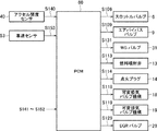
図8及び図9を参照して、本発明の実施形態において行われる、吸気バルブ12及び排気バルブ17の動作タイミングの制御について具体的に説明する。図8は、横軸にクランク角を示し、縦軸にバルブリフト量を示しており、クランク角に応じた排気バルブ17の動作(グラフG11参照)と、クランク角に応じた吸気バルブ12の動作(グラフG12参照)とを重ねて示している。図9では、エンジン負荷に応じて吸気バルブ12の動作タイミングを規定したマップを(a)に示し、エンジン負荷に応じて排気バルブ17の動作タイミングを規定したマップを(b)に示している。
With reference to FIG. 8 and FIG. 9, the control of the operation timing of the
吸気バルブ12は、図9(a)に示すマップの動作タイミングに従って、可変吸気バルブ機構18を介して動作され、排気バルブ17は、図9(b)に示すマップの動作タイミングに従って、可変排気バルブ機構19を介して動作される。ここで、吸気バルブ12及び排気バルブ17は、それぞれ、可変吸気バルブ機構18及び可変排気バルブ機構19によって、開弁時間(開弁期間の長さ)が固定された状態にて、開弁時期及び閉弁時期の両方が連動して変化される。つまり、動作タイミングが遅角側に設定されると、開弁時期及び閉弁時期の両方が遅角側に設定され、一方で、動作タイミングが進角側に設定されると、開弁時期及び閉弁時期の両方が進角側に設定されることとなる。
The
図9(a)及び(b)に示すように、本実施形態では、低負荷域において、吸気バルブ12及び排気バルブ17の動作タイミングを遅角側に設定している。これにより、低負荷域において、排気バルブ17の閉弁時期が遅角されると共に(図8中の矢印A11参照)、吸気バルブ12の閉弁時期が遅角される(図8中の矢印A12参照)。本実施形態では、PCM60は、スロットルバルブ6を開き側に制御しつつ、このように吸気バルブ12の閉弁時期を遅角させる。これにより、スロットルバルブ6が開き側にあることでインマニ圧力が確保されてポンピングロスを低減することができると共に、この状態において吸気バルブ12の閉弁時期を遅角側で調整することで吸気の充填量を適切に制御することができる。また、排気バルブ17の閉弁時期を遅角することで、吸気行程において排気バルブ17と吸気バルブ12とのバルブオーバーラップ期間が生じてエンジン10の気筒に内部EGRガスが導入されるため、上記したように外部EGRガスを導入する場合と同様に、ポンピングロスを適切に低減することができる。なお、目標充填量を実現しつつ、ポンピングロスが適切に抑制されるように、吸気バルブ12を介した新気量と排気バルブ17を介した内部EGR量とのバランスなどを考慮して、スロットルバルブ6の開度、吸気バルブ12の閉弁時期及び排気バルブ17の閉弁時期のそれぞれを設定するのがよい。
As shown in FIGS. 9A and 9B, in this embodiment, the operation timing of the
次に、図10を参照して、本発明の実施形態によるEGR率マップに規定された、エンジン回転数とEGR率との関係について説明する。具体的には、図10は、EGR率マップに関して、同一のエンジン負荷で見たときのエンジン回転数(横軸)とEGR率(縦軸)との関係を示すグラフである。 Next, with reference to FIG. 10, the relationship between the engine speed and the EGR rate defined in the EGR rate map according to the embodiment of the present invention will be described. Specifically, FIG. 10 is a graph showing the relationship between the engine speed (horizontal axis) and the EGR rate (vertical axis) when viewed at the same engine load with respect to the EGR rate map.
図10に示すように、本実施形態では、同一のエンジン負荷で見たときに、エンジン回転数が大きくなるほど、EGR率を大きくするようにEGR率マップが規定されている。また、本実施形態では、エンジン回転数が所定値N1以上の領域では、エンジン回転数によらずにEGR率がほぼ一定になるようにEGR率マップが規定されている。 As shown in FIG. 10, in this embodiment, when viewed at the same engine load, the EGR rate map is defined so that the EGR rate increases as the engine speed increases. In the present embodiment, the EGR rate map is defined so that the EGR rate is substantially constant regardless of the engine speed in the region where the engine speed is equal to or greater than the predetermined value N1.
図10に示すようにEGR率マップを規定している理由は以下の通りである。エンジン10の低回転域では、排気ガス量が少ないため排気圧が低くなるので、エミッションなどの観点から、EGRガス量を少なくするのが望ましい。一方で、エンジン回転数が高くなると、排気ガス量が多くなり排気圧が高くなるので、EGRガス量を増加させることができる。したがって、本実施形態では、エンジン回転数が大きくなるほど、EGR率を大きくしている(図10参照)。こうすることで、高回転域では、EGRガスの導入による燃費改善効果や熱負荷軽減効果を向上させることができ、一方で、低回転域では、EGR率を小さくするので、EGRガスの導入によって引き起こされるエミッションの悪化などを抑制することができる。
The reason why the EGR rate map is defined as shown in FIG. 10 is as follows. In the low speed range of the
他方で、エンジン回転数が所定値N1以上の高回転域では、運転状態の変化によりEGR率が大きく変化するため、EGR率の制御性が低下する傾向にある。具体的には、EGR制御における制御値と実際の値とのずれが生じ、空燃比が変動してエミッションが悪化したり、燃焼が不安定になったりする。したがって、本実施形態では、エンジン回転数が所定値N1以上の領域では、エンジン回転数によらずにEGR率をほぼ一定にしている(図10参照)。こうすることで、エンジン回転数が所定値N1以上の領域において、EGRガスの導入による燃費改善効果や熱負荷軽減効果を確保しつつ、EGR率の制御性を確保してエミッションや燃焼安定性の悪化を適切に抑制することができる。 On the other hand, in the high engine speed range where the engine speed is equal to or greater than the predetermined value N1, the controllability of the EGR rate tends to decrease because the EGR rate changes greatly due to changes in the operating state. Specifically, a deviation between the control value in the EGR control and the actual value occurs, the air-fuel ratio fluctuates, the emission deteriorates, and the combustion becomes unstable. Therefore, in the present embodiment, in the region where the engine speed is equal to or greater than the predetermined value N1, the EGR rate is made substantially constant regardless of the engine speed (see FIG. 10). In this way, in the region where the engine speed is greater than or equal to the predetermined value N1, the control of the EGR rate is ensured to ensure the emission and combustion stability while ensuring the fuel efficiency improvement effect and the thermal load reduction effect by introducing the EGR gas. Deterioration can be appropriately suppressed.
なお、図10に示すように、低回転域では、具体的にはアイドル回転数付近の低回転域では、EGR率がほぼ0に設定されている。このような回転域は使用頻度が低いため、EGRガスを導入するメリットを得るよりもEGRガスを導入するデメリット(エミッションや燃焼安定性の悪化)を回避すべく、EGRガスを導入しないようにしている。 As shown in FIG. 10, in the low rotation range, specifically, in the low rotation range near the idle rotation number, the EGR rate is set to almost zero. Since such a rotation region is less frequently used, avoid introducing the EGR gas in order to avoid the disadvantages of introducing the EGR gas (deterioration of emission and combustion stability) rather than obtaining the advantage of introducing the EGR gas. Yes.
次に、図11を参照して、本発明の実施形態によるEGR率マップに規定された、EGRガスの導入を制限するためのエンジン負荷(EGR導入制限負荷)について説明する。本実施形態では、EGR率マップ上にエンジン回転数に応じたEGR導入制限負荷を規定し、エンジン負荷が当該EGR導入制限負荷以上である領域においてEGRガスの導入を制限するようにしている。図11は、EGR率マップに規定された、エンジン回転数(横軸)とEGR導入制限負荷(縦軸)との関係を示すグラフである。 Next, an engine load (EGR introduction restriction load) for restricting the introduction of EGR gas, which is defined in the EGR rate map according to the embodiment of the present invention, will be described with reference to FIG. In the present embodiment, an EGR introduction restriction load corresponding to the engine speed is defined on the EGR rate map, and the introduction of EGR gas is restricted in a region where the engine load is equal to or greater than the EGR introduction restriction load. FIG. 11 is a graph showing the relationship between the engine speed (horizontal axis) and the EGR introduction restriction load (vertical axis) defined in the EGR rate map.
図11に示すように、本実施形態では、エンジン負荷がEGR導入制限負荷以上の領域ではEGRガスを導入しないようにし(この場合「EGR率=0」に設定される)、エンジン負荷がEGR導入制限負荷未満の領域においてEGRガスを導入するように(この場合EGR率が0よりも大きな値に設定される)、EGR率マップが規定されている。また、本実施形態では、エンジン回転数が大きくなるほど、EGR導入制限負荷が大きくなるように、EGR率マップが規定されている。そのため、エンジン回転数が大きくなると、EGRガスの導入の制限が緩和されて、EGRガスが導入される負荷域が広くなっていく。 As shown in FIG. 11, in the present embodiment, EGR gas is not introduced in an area where the engine load is equal to or greater than the EGR introduction restriction load (in this case, “EGR rate = 0” is set), and the engine load is EGR introduction. An EGR rate map is defined so that EGR gas is introduced in a region below the limit load (in this case, the EGR rate is set to a value larger than 0). In the present embodiment, the EGR rate map is defined so that the EGR introduction restriction load increases as the engine speed increases. Therefore, when the engine speed increases, the restriction on the introduction of EGR gas is relaxed, and the load range into which EGR gas is introduced becomes wider.
図11に示すようにEGR率マップを規定している理由は以下の通りである。特にターボ過給機4による過給を行う低回転高負荷域では、排気圧がインマニ圧よりも相対的に低い状態となって、EGRガスを導入するとEGRガスが逆流してしまう場合がある。そのため、低回転域では、エンジン負荷に対して制限を課した上でEGRガスを導入することが望ましい、つまりエンジン負荷がある負荷未満である領域(具体的には過給域でない領域)でのみEGRガスを導入することが望ましい。一方で、エンジン回転数が高くなると、排気ガス量が多くなり排気圧が高くなるため、上記のようなEGRガスの逆流が生じにくくなるので、EGRガスを導入するときにエンジン負荷に対して課す制限を緩和するのが望ましい、つまりEGRガスを導入するエンジン負荷の領域を広げることが望ましい。したがって、本実施形態では、エンジン回転数が大きくなるほど、EGR導入制限負荷を大きくしている。このようなEGR導入制限負荷を用いることで、低回転域では、EGR導入制限負荷によってEGRガスの導入を制限して、EGRガスの逆流や、EGRガスの導入に起因するエミッションの悪化などを抑制することができ、高回転域では、そのようなEGRガスの導入の制限を緩和して、過給域(高負荷域)でも適切にEGRガスを導入することができ、燃費改善効果や熱負荷軽減効果を得ることができる。 The reason why the EGR rate map is defined as shown in FIG. 11 is as follows. In particular, in a low-rotation and high-load region where supercharging by the turbocharger 4 is performed, the exhaust pressure may be relatively lower than the intake manifold pressure, and when EGR gas is introduced, the EGR gas may flow backward. For this reason, it is desirable to introduce EGR gas after imposing restrictions on the engine load in the low engine speed range, that is, only in a region where the engine load is less than a certain load (specifically, a region that is not a supercharging region). It is desirable to introduce EGR gas. On the other hand, when the engine speed increases, the amount of exhaust gas increases and the exhaust pressure increases, so that the backflow of EGR gas as described above is less likely to occur. Therefore, when EGR gas is introduced, it is imposed on the engine load. It is desirable to relax the restriction, that is, to widen the area of the engine load that introduces EGR gas. Therefore, in this embodiment, the EGR introduction restriction load is increased as the engine speed increases. By using such EGR introduction restriction load, the introduction of EGR gas is restricted by the EGR introduction restriction load in the low rotation range, and the backflow of EGR gas and the deterioration of emission caused by the introduction of EGR gas are suppressed. In the high rotation range, the restriction on the introduction of such EGR gas can be relaxed, and the EGR gas can be introduced appropriately even in the supercharging range (high load range). A reduction effect can be obtained.
<作用効果>
次に、本発明の実施形態によるエンジンの制御装置の作用効果について説明する。
<Effect>
Next, functions and effects of the engine control apparatus according to the embodiment of the present invention will be described.
本実施形態では、少なくとも高負荷域R11においてEGRガスを導入し、また、同一のエンジン回転数において、高負荷域R11では中負荷域R12よりもEGR率を小さくする。これにより、高負荷域R11においてEGRガスの導入を適切に確保して、エンジン10の温度(ボア間温度など)の低下や熱害抑制のための燃料増量の低減などを適切に実現しつつ、高負荷域R11でのEGRガス量をある程度抑えることにより(具体的には高負荷域R11でのEGR率を中負荷域R12よりも小さくする)、EGRガス導入によって引き起こされるエンジン出力の低下や燃焼安定性の悪化を適切に抑制することができる。更に、中負荷域R12において比較的多量のEGRガスを導入することで、ポンピングロスを確実に低減して、燃費を効果的に改善することが可能となる。加えて、そのようなEGRガスの導入によりノッキングを抑制することができ、その結果、ノッキング抑制のための点火時期の遅角を緩和することができる、つまり、EGRガスを導入しない場合よりも点火時期を進角させることができる。これによっても燃費を改善することが可能となる。 In the present embodiment, EGR gas is introduced at least in the high load region R11, and the EGR rate is made smaller in the high load region R11 than in the medium load region R12 at the same engine speed. As a result, while appropriately introducing the EGR gas in the high load region R11, appropriately reducing the temperature of the engine 10 (such as the temperature between the bores) and reducing the amount of fuel to suppress thermal damage, By suppressing the amount of EGR gas in the high load region R11 to some extent (specifically, making the EGR rate in the high load region R11 smaller than that in the medium load region R12), the engine output is reduced or burned due to the introduction of EGR gas. Deterioration of stability can be appropriately suppressed. Further, by introducing a relatively large amount of EGR gas in the medium load region R12, it is possible to reliably reduce the pumping loss and effectively improve the fuel consumption. In addition, knocking can be suppressed by introducing such EGR gas, and as a result, the retard of the ignition timing for suppressing knocking can be mitigated, that is, ignition can be performed more than when EGR gas is not introduced. The time can be advanced. This also makes it possible to improve fuel efficiency.
特に、本実施形態では、高負荷で且つ高回転側である領域や過給域といったEGRガスを導入することが望ましい領域において、EGRガスを適切に導入ことができる。よって、そのような領域においてノッキング抑制や熱負荷軽減や燃料増量の低減などを適切に実現することができる。 In particular, in the present embodiment, the EGR gas can be appropriately introduced in a region where it is desirable to introduce the EGR gas, such as a region having a high load and a high rotation side, or a supercharging region. Therefore, in such a region, it is possible to appropriately realize knocking suppression, thermal load reduction, fuel increase reduction, and the like.
また、本実施形態によれば、低負荷域R13ではEGRガスを導入しないので、低負荷域R13でEGRガスを導入した場合に生じ得る燃焼安定性やエミッションの悪化を適切に抑制することができる。 In addition, according to the present embodiment, since EGR gas is not introduced in the low load region R13, it is possible to appropriately suppress deterioration in combustion stability and emission that may occur when EGR gas is introduced in the low load region R13. .
また、本実施形態によれば、エンジン負荷が高くなるほど、点火時期を遅角側に設定するので、高負荷域で発生し得るノッキングを抑制しつつ、EGR制御を適切に実行することができる。 In addition, according to the present embodiment, the ignition timing is set to the retard side as the engine load becomes higher. Therefore, EGR control can be appropriately executed while suppressing knocking that may occur in a high load region.
<変形例>
上記した実施形態では、低負荷域R13においてEGR率をほぼ0に設定してEGRガスを導入しないようにしたが(図7参照)、低負荷域R13においてEGR率を0に設定せずに少量のEGRガス(高負荷域R11及び中負荷域R12よりも小さな流量のEGRガス)を導入してもよい。
<Modification>
In the above-described embodiment, the EGR rate is set to approximately 0 in the low load region R13 so that EGR gas is not introduced (see FIG. 7), but the EGR rate is not set to 0 in the low load region R13 and a small amount. EGR gas (EGR gas having a smaller flow rate than the high load region R11 and the medium load region R12) may be introduced.
また、上記した実施形態では、エンジン回転数が所定値N1以上の領域では、エンジン回転数によらずにEGR率をほぼ一定に設定していたが(図10参照)、エンジン回転数に応じてEGR率を大きくしてもよい。その場合、エンジン回転数が所定値N1以上の領域では、エンジン回転数が所定値N1未満の領域よりも、エンジン回転数に応じたEGR率の変化度合い(エンジン回転数の上昇に応じたEGR率の増加率)が小さくなるように、EGR率マップを規定すればよい。 In the above-described embodiment, the EGR rate is set to be almost constant regardless of the engine speed in the region where the engine speed is equal to or greater than the predetermined value N1 (see FIG. 10). The EGR rate may be increased. In this case, in the region where the engine speed is equal to or greater than the predetermined value N1, the degree of change in the EGR rate according to the engine speed (EGR rate according to the increase in the engine speed) is greater than in the region where the engine speed is less than the predetermined value N1. The EGR rate map may be defined so that the increase rate of the
また、上記した実施形態では、エンジン回転数に基づきEGR導入制限負荷を設定していたが、エンジン回転数以外のパラメータに基づき、具体的には排気ガス量を表すパラメータに基づき、EGR導入制限負荷を設定してもよい。 In the embodiment described above, the EGR introduction restriction load is set based on the engine speed. However, based on parameters other than the engine speed, specifically, based on a parameter representing the exhaust gas amount, the EGR introduction restriction load is set. May be set.
1 吸気通路
4 ターボ過給機
4a コンプレッサ
4b タービン
6 スロットルバルブ
10 エンジン
12 吸気バルブ
13 燃料噴射弁
14 点火プラグ
17 排気バルブ
25 排気通路
26 EGR装置
27 EGR通路
28 EGRクーラ
29 EGRバルブ
45、49 圧力センサ
60 PCM
100 エンジンシステム
DESCRIPTION OF SYMBOLS 1 Intake passage 4
100 engine system
Claims (5)
吸気通路上に設けられたコンプレッサと排気通路上に設けられたタービンとを備えるターボ過給機と、
ターボ過給機のタービンの上流側とターボ過給機のコンプレッサの下流側とに接続され、排気通路内の排気ガスをEGRガスとして吸気通路に還流させるEGR通路と、EGR通路を通過するEGRガス量を調整するEGRバルブと、EGR通路を通過するEGRガスを冷却するEGRクーラと、を備えるEGR装置と、
エンジンの運転状態に基づいて、EGR装置によって還流させるEGRガスのEGR率を調整するようにEGRバルブを制御するEGR制御手段と、を有し、
上記車両用エンジンの制御装置は、排気通路内の排気ガスをコンプレッサの下流側の吸気通路へと還流させる上記EGR装置のみを具備し、排気通路内の排気ガスをコンプレッサの上流側の吸気通路へと還流させるEGR装置を具備しておらず、
上記EGR制御手段は、
エンジンの高負荷側の第1領域及びこの第1領域よりも低負荷側の第2領域において、EGR装置によってEGRガスを吸気通路に還流させるようにEGRバルブを制御し、
同一のエンジン回転数において、上記第1領域では上記第2領域よりもEGR率が小さくなるようにEGRバルブを制御し、
同一のエンジン回転数において、上記第1領域において適用するEGR率が、上記第2領域よりも低負荷側の第3領域において適用するEGR率よりも大きくなるようにEGRバルブを制御し、
上記第1領域では、エンジンの負荷が高くなるほど、EGR率が小さくなるようにEGRバルブを制御し、
上記第1領域では、エンジンのボア間のダメージを抑制するのに十分な量のEGRガスを還流させるようにEGRバルブを制御する、ことを特徴とする車両用エンジンの制御装置。 A control device for a vehicle engine,
A turbocharger comprising a compressor provided on the intake passage and a turbine provided on the exhaust passage;
An EGR passage connected to the upstream side of the turbine of the turbocharger and the downstream side of the compressor of the turbocharger and returning the exhaust gas in the exhaust passage as EGR gas to the intake passage, and EGR gas passing through the EGR passage An EGR device comprising: an EGR valve that adjusts the amount; and an EGR cooler that cools the EGR gas that passes through the EGR passage;
EGR control means for controlling the EGR valve so as to adjust the EGR rate of the EGR gas recirculated by the EGR device based on the operating state of the engine,
The vehicle engine control device includes only the EGR device that recirculates the exhaust gas in the exhaust passage to the intake passage on the downstream side of the compressor, and the exhaust gas in the exhaust passage to the intake passage on the upstream side of the compressor. It does not have an EGR device for refluxing,
The EGR control means is
In the first region on the high load side of the engine and in the second region on the lower load side than the first region, the EGR valve is controlled so that the EGR gas is recirculated to the intake passage by the EGR device,
At the same engine speed, the EGR valve is controlled so that the EGR rate is smaller in the first region than in the second region,
Controlling the EGR valve so that the EGR rate applied in the first region at the same engine speed is larger than the EGR rate applied in the third region on the lower load side than the second region;
In the first region, the EGR valve is controlled so that the EGR rate decreases as the engine load increases.
In the first region, the EGR valve is controlled to recirculate an amount of EGR gas sufficient to suppress damage between the engine bores.
Priority Applications (5)
| Application Number | Priority Date | Filing Date | Title |
|---|---|---|---|
| JP2016042398A JP6380914B2 (en) | 2016-03-04 | 2016-03-04 | Engine control device |
| CN201780003127.0A CN108026845A (en) | 2016-03-04 | 2017-02-03 | The control device of engine |
| US15/757,624 US10408144B2 (en) | 2016-03-04 | 2017-02-03 | Engine control device |
| PCT/JP2017/004113 WO2017150076A1 (en) | 2016-03-04 | 2017-02-03 | Engine control device |
| DE112017000112.9T DE112017000112T5 (en) | 2016-03-04 | 2017-02-03 | Motor controller |
Applications Claiming Priority (1)
| Application Number | Priority Date | Filing Date | Title |
|---|---|---|---|
| JP2016042398A JP6380914B2 (en) | 2016-03-04 | 2016-03-04 | Engine control device |
Publications (2)
| Publication Number | Publication Date |
|---|---|
| JP2017155724A JP2017155724A (en) | 2017-09-07 |
| JP6380914B2 true JP6380914B2 (en) | 2018-08-29 |
Family
ID=59743960
Family Applications (1)
| Application Number | Title | Priority Date | Filing Date |
|---|---|---|---|
| JP2016042398A Active JP6380914B2 (en) | 2016-03-04 | 2016-03-04 | Engine control device |
Country Status (5)
| Country | Link |
|---|---|
| US (1) | US10408144B2 (en) |
| JP (1) | JP6380914B2 (en) |
| CN (1) | CN108026845A (en) |
| DE (1) | DE112017000112T5 (en) |
| WO (1) | WO2017150076A1 (en) |
Families Citing this family (3)
| Publication number | Priority date | Publication date | Assignee | Title |
|---|---|---|---|---|
| JP2019035439A (en) | 2017-08-10 | 2019-03-07 | Kyb株式会社 | Buffer |
| CN113756998A (en) * | 2021-09-02 | 2021-12-07 | 宁波协诚电动工具有限公司 | Method for acquiring air flow and commercial vehicle |
| GB2614357A (en) * | 2022-06-30 | 2023-07-05 | Bamford Excavators Ltd | A method and system for controlling the acceleration of a vehicle |
Family Cites Families (15)
| Publication number | Priority date | Publication date | Assignee | Title |
|---|---|---|---|---|
| US6968825B2 (en) * | 2003-06-06 | 2005-11-29 | Mazda Motor Corporation | Control device for spark-ignition engine |
| JP4285528B2 (en) * | 2006-11-06 | 2009-06-24 | トヨタ自動車株式会社 | Exhaust gas recirculation system for internal combustion engines |
| JP2009250209A (en) * | 2008-04-10 | 2009-10-29 | Toyota Motor Corp | Exhaust gas recirculating device of internal combustion engine |
| JP5092962B2 (en) | 2008-07-18 | 2012-12-05 | トヨタ自動車株式会社 | Control device for an internal combustion engine with a supercharger |
| US9261052B2 (en) * | 2011-12-01 | 2016-02-16 | Toyota Jidosha Kabushiki Kaisha | Failure diagnosis apparatus of EGR system |
| JP5948897B2 (en) * | 2012-01-25 | 2016-07-06 | 日産自動車株式会社 | Internal combustion engine |
| JP2013194635A (en) * | 2012-03-21 | 2013-09-30 | Toyota Motor Corp | Internal combustion engine control device |
| JP5920237B2 (en) * | 2013-02-05 | 2016-05-18 | マツダ株式会社 | Control device for spark ignition engine |
| JP6163914B2 (en) * | 2013-06-27 | 2017-07-19 | いすゞ自動車株式会社 | Diesel engine and control method thereof |
| US9284909B2 (en) * | 2013-08-23 | 2016-03-15 | Ford Global Technologies, Llc | Method and system for knock control |
| US9371783B2 (en) * | 2013-11-08 | 2016-06-21 | Ford Global Technologies, Llc | Method and system for improved dilution tolerance |
| US9739221B2 (en) * | 2014-01-16 | 2017-08-22 | Ford Global Technologies, Llc | Method to improve blowthrough and EGR via split exhaust |
| JP5886356B2 (en) * | 2014-04-15 | 2016-03-16 | 川崎重工業株式会社 | Engine system and control method |
| JP6252337B2 (en) * | 2014-04-23 | 2017-12-27 | 日産自動車株式会社 | Engine control device |
| US9534530B2 (en) * | 2014-08-07 | 2017-01-03 | Ford Global Technologies, Llc | Dedicated-EGR cylinder with variable charge motion |
-
2016
- 2016-03-04 JP JP2016042398A patent/JP6380914B2/en active Active
-
2017
- 2017-02-03 DE DE112017000112.9T patent/DE112017000112T5/en not_active Withdrawn
- 2017-02-03 US US15/757,624 patent/US10408144B2/en active Active
- 2017-02-03 WO PCT/JP2017/004113 patent/WO2017150076A1/en active Application Filing
- 2017-02-03 CN CN201780003127.0A patent/CN108026845A/en active Pending
Also Published As
| Publication number | Publication date |
|---|---|
| US10408144B2 (en) | 2019-09-10 |
| WO2017150076A1 (en) | 2017-09-08 |
| CN108026845A (en) | 2018-05-11 |
| JP2017155724A (en) | 2017-09-07 |
| US20180245529A1 (en) | 2018-08-30 |
| DE112017000112T5 (en) | 2018-05-30 |
Similar Documents
| Publication | Publication Date | Title |
|---|---|---|
| JP2010164045A (en) | Intake amount control device for supercharged engine | |
| JP2006046293A (en) | Intake air control device for internal combustion engine | |
| US20180266365A1 (en) | Exhaust gas control apparatus of internal combustion engine | |
| JP6380914B2 (en) | Engine control device | |
| JP2007224740A (en) | Fuel injection control device of internal combustion engine | |
| JP5418692B2 (en) | Engine control device | |
| JP2012097639A (en) | Control device for internal combustion engine | |
| JP2017066934A (en) | Engine control device | |
| JP6380915B2 (en) | Engine control device | |
| JP6312049B2 (en) | Engine control device | |
| JP2013130121A (en) | Exhaust gas recirculation system for spark-ignition-type internal combustion engine | |
| JP6127906B2 (en) | Control device for internal combustion engine | |
| JP5594236B2 (en) | Control device for internal combustion engine | |
| JP6312048B2 (en) | Engine control device | |
| JP2007303355A (en) | Egr control device for internal combustion engine | |
| JP2014190264A (en) | Device for controlling internal combustion engine | |
| CN110259589B (en) | Control device for internal combustion engine | |
| WO2017150077A1 (en) | Engine control device | |
| WO2010095258A1 (en) | Internal combustion engine | |
| JP5338709B2 (en) | Control device for internal combustion engine | |
| JP5800090B2 (en) | Control device for internal combustion engine | |
| JP2017180245A (en) | Controller of engine | |
| JP2010024973A (en) | Control device for internal combustion engine with supercharger | |
| JP6406153B2 (en) | Engine control device | |
| JP5948897B2 (en) | Internal combustion engine |
Legal Events
| Date | Code | Title | Description |
|---|---|---|---|
| A131 | Notification of reasons for refusal |
Free format text: JAPANESE INTERMEDIATE CODE: A131 Effective date: 20171211 |
|
| A521 | Request for written amendment filed |
Free format text: JAPANESE INTERMEDIATE CODE: A523 Effective date: 20180209 |
|
| A131 | Notification of reasons for refusal |
Free format text: JAPANESE INTERMEDIATE CODE: A131 Effective date: 20180402 |
|
| A521 | Request for written amendment filed |
Free format text: JAPANESE INTERMEDIATE CODE: A523 Effective date: 20180530 |
|
| TRDD | Decision of grant or rejection written | ||
| A01 | Written decision to grant a patent or to grant a registration (utility model) |
Free format text: JAPANESE INTERMEDIATE CODE: A01 Effective date: 20180709 |
|
| R150 | Certificate of patent or registration of utility model |
Ref document number: 6380914 Country of ref document: JP Free format text: JAPANESE INTERMEDIATE CODE: R150 |
|
| A61 | First payment of annual fees (during grant procedure) |
Free format text: JAPANESE INTERMEDIATE CODE: A61 Effective date: 20180722 |