JP6380574B2 - Arrangement structure of auxiliary equipment for vehicle - Google Patents
Arrangement structure of auxiliary equipment for vehicle Download PDFInfo
- Publication number
- JP6380574B2 JP6380574B2 JP2017030639A JP2017030639A JP6380574B2 JP 6380574 B2 JP6380574 B2 JP 6380574B2 JP 2017030639 A JP2017030639 A JP 2017030639A JP 2017030639 A JP2017030639 A JP 2017030639A JP 6380574 B2 JP6380574 B2 JP 6380574B2
- Authority
- JP
- Japan
- Prior art keywords
- harness
- vehicle
- dcm
- vertical wall
- bracket
- Prior art date
- Legal status (The legal status is an assumption and is not a legal conclusion. Google has not performed a legal analysis and makes no representation as to the accuracy of the status listed.)
- Active
Links
Images


Classifications
-
- B—PERFORMING OPERATIONS; TRANSPORTING
- B60—VEHICLES IN GENERAL
- B60R—VEHICLES, VEHICLE FITTINGS, OR VEHICLE PARTS, NOT OTHERWISE PROVIDED FOR
- B60R16/00—Electric or fluid circuits specially adapted for vehicles and not otherwise provided for; Arrangement of elements of electric or fluid circuits specially adapted for vehicles and not otherwise provided for
- B60R16/02—Electric or fluid circuits specially adapted for vehicles and not otherwise provided for; Arrangement of elements of electric or fluid circuits specially adapted for vehicles and not otherwise provided for electric constitutive elements
- B60R16/023—Electric or fluid circuits specially adapted for vehicles and not otherwise provided for; Arrangement of elements of electric or fluid circuits specially adapted for vehicles and not otherwise provided for electric constitutive elements for transmission of signals between vehicle parts or subsystems
- B60R16/0239—Electronic boxes
-
- B—PERFORMING OPERATIONS; TRANSPORTING
- B60—VEHICLES IN GENERAL
- B60R—VEHICLES, VEHICLE FITTINGS, OR VEHICLE PARTS, NOT OTHERWISE PROVIDED FOR
- B60R11/00—Arrangements for holding or mounting articles, not otherwise provided for
- B60R11/02—Arrangements for holding or mounting articles, not otherwise provided for for radio sets, television sets, telephones, or the like; Arrangement of controls thereof
- B60R11/0264—Arrangements for holding or mounting articles, not otherwise provided for for radio sets, television sets, telephones, or the like; Arrangement of controls thereof for control means
-
- B—PERFORMING OPERATIONS; TRANSPORTING
- B60—VEHICLES IN GENERAL
- B60R—VEHICLES, VEHICLE FITTINGS, OR VEHICLE PARTS, NOT OTHERWISE PROVIDED FOR
- B60R16/00—Electric or fluid circuits specially adapted for vehicles and not otherwise provided for; Arrangement of elements of electric or fluid circuits specially adapted for vehicles and not otherwise provided for
- B60R16/02—Electric or fluid circuits specially adapted for vehicles and not otherwise provided for; Arrangement of elements of electric or fluid circuits specially adapted for vehicles and not otherwise provided for electric constitutive elements
- B60R16/0207—Wire harnesses
- B60R16/0215—Protecting, fastening and routing means therefor
-
- B—PERFORMING OPERATIONS; TRANSPORTING
- B60—VEHICLES IN GENERAL
- B60R—VEHICLES, VEHICLE FITTINGS, OR VEHICLE PARTS, NOT OTHERWISE PROVIDED FOR
- B60R21/00—Arrangements or fittings on vehicles for protecting or preventing injuries to occupants or pedestrians in case of accidents or other traffic risks
-
- B—PERFORMING OPERATIONS; TRANSPORTING
- B60—VEHICLES IN GENERAL
- B60R—VEHICLES, VEHICLE FITTINGS, OR VEHICLE PARTS, NOT OTHERWISE PROVIDED FOR
- B60R11/00—Arrangements for holding or mounting articles, not otherwise provided for
- B60R2011/0001—Arrangements for holding or mounting articles, not otherwise provided for characterised by position
- B60R2011/0003—Arrangements for holding or mounting articles, not otherwise provided for characterised by position inside the vehicle
- B60R2011/0007—Mid-console
-
- B—PERFORMING OPERATIONS; TRANSPORTING
- B60—VEHICLES IN GENERAL
- B60R—VEHICLES, VEHICLE FITTINGS, OR VEHICLE PARTS, NOT OTHERWISE PROVIDED FOR
- B60R21/00—Arrangements or fittings on vehicles for protecting or preventing injuries to occupants or pedestrians in case of accidents or other traffic risks
- B60R2021/0002—Type of accident
- B60R2021/0006—Lateral collision
-
- B—PERFORMING OPERATIONS; TRANSPORTING
- B60—VEHICLES IN GENERAL
- B60R—VEHICLES, VEHICLE FITTINGS, OR VEHICLE PARTS, NOT OTHERWISE PROVIDED FOR
- B60R21/00—Arrangements or fittings on vehicles for protecting or preventing injuries to occupants or pedestrians in case of accidents or other traffic risks
- B60R2021/0027—Post collision measures, e.g. notifying emergency services
-
- B—PERFORMING OPERATIONS; TRANSPORTING
- B60—VEHICLES IN GENERAL
- B60R—VEHICLES, VEHICLE FITTINGS, OR VEHICLE PARTS, NOT OTHERWISE PROVIDED FOR
- B60R21/00—Arrangements or fittings on vehicles for protecting or preventing injuries to occupants or pedestrians in case of accidents or other traffic risks
- B60R21/02—Occupant safety arrangements or fittings, e.g. crash pads
- B60R2021/0273—Occupant safety arrangements or fittings, e.g. crash pads automatically movable to an operative position, e.g. in case of collision or impending collision
-
- B—PERFORMING OPERATIONS; TRANSPORTING
- B60—VEHICLES IN GENERAL
- B60R—VEHICLES, VEHICLE FITTINGS, OR VEHICLE PARTS, NOT OTHERWISE PROVIDED FOR
- B60R21/00—Arrangements or fittings on vehicles for protecting or preventing injuries to occupants or pedestrians in case of accidents or other traffic risks
- B60R21/02—Occupant safety arrangements or fittings, e.g. crash pads
Description
この発明は、車体における、車幅方向に並んだシートの間に補機を配設する車両用補機の配設構造に関する。 The present invention relates to a vehicle auxiliary machine arrangement structure in which auxiliary machines are arranged between seats arranged in the vehicle width direction in a vehicle body.
近年、車両の事故が発生した際に乗員の早期の救助を可能とすべく、車両から、サービス会社を経由して警察・消防・医療機関などに、車両やユーザーを特定する情報、事故状況、車両の位置などを送信するように構成された、いわゆる緊急自動通報システムが普及しつつある。 In recent years, in order to enable early rescue of occupants in the event of a vehicle accident, information from the vehicle to the police, fire department, medical institution, etc. via the service company, information on the accident, A so-called emergency automatic notification system configured to transmit the position of a vehicle or the like is becoming widespread.
このシステムを実現するために、車両には、救助団体に情報を送信するための補機として特許文献1に例示されるような車載緊急通報装置(以下「DCM」という)が搭載される。
In order to realize this system, the vehicle is equipped with an in-vehicle emergency call device (hereinafter referred to as “DCM”) as exemplified in
このようなDCMをはじめとして、例えば乗員救出のため自動でドアロックを解除する装置など車両の事故時においても所定の機能を果たす必要のある補機は、車体の中にでも事故の影響を受け難い箇所として、センタトンネル等の車幅方向に並んだシート間に設けられることが好ましい。 Auxiliary equipment that needs to perform a specified function in the event of a vehicle accident, such as a device that automatically releases the door lock to rescue the passenger, such as DCM, is also affected by the accident in the vehicle body. As a difficult place, it is preferable to be provided between seats arranged in the vehicle width direction such as a center tunnel.
ところで特許文献2には、加速度を検出する加速度センサと、左右のフロントシートに対して車幅方向外側に配設された側突用エアバッグ装置と、サイドドアに設けられ、側突荷重を上記加速度センサに2段階で伝達する2段階荷重伝達部と、加速度センサからの信号に基づいて側突用エアバッグ装置の作動を制御するコントローラを備えた側突検知システムが開示されている。
By the way, in
そして、この特許文献2の側突検知システムにおいても、車両に事故が発生しても補機としてのコントローラが故障しないように該コントローラを左右両シート間に配設することによって、側突時に加速度センサからの信号に基づいて側突用エアバッグ装置が適切に作動するように構成としたものである。
In the side collision detection system of
しかしながら、補機としてのコントローラは、左右両シート間に配設された構成となるため、側突時においては、シートが該コントローラ側に変位して直接的に干渉することで本来の機能を果たさないおそれがある。 However, since the controller as an auxiliary machine is arranged between the left and right sheets, the original function is achieved by the sheet being displaced to the controller side and interfering directly in the event of a side collision. There is a risk of not.
側突時においてもコントローラは、側突用エアバッグ装置の適切な作動を制御する必要があるにも関わらず、特許文献2には、このような課題に対する対策について何ら開示されておらず検討の余地がある。
Even in the case of a side collision, the controller needs to control the appropriate operation of the side collision airbag device, but
特に、補機に対して電源供給や信号の送受信を行うために車体側から延びるハーネスを補機に接続したハーネス接続部が、左右両シートの一方のシート側に位置するように配置された補機の配設構造においては、側突時に一方のシートがハーネス接続部に直接干渉して破損しないように対策を施す必要がある。 In particular, a harness connecting portion that connects a harness extending from the vehicle body side to the auxiliary machine to supply power to the auxiliary machine and transmit / receive signals is arranged on one of the left and right seats. In the arrangement structure of the machine, it is necessary to take measures so that one of the seats does not directly interfere with the harness connecting portion and breaks at the time of a side collision.
そこでこの発明は補機が側突時にシートと直接的に干渉する可能性を低減する構造を提供することを目的とする。 Accordingly, an object of the present invention is to provide a structure that reduces the possibility that an auxiliary machine directly interferes with a seat in a side collision.
この発明は、車体における、車幅方向に並んだシートの間に補機を配設する車両用補機の配設構造であって、上記補機が取り付けられるとともに車体に固定されるブラケットを有し、上記補機は、ハーネスが接続されるハーネス接続部を有するとともに該ハーネス接続部が一方のシート側に位置するように配置され、上記ブラケットには、ベース面と、上記補機と各シートの間に、車幅方向に互いに離間するように上記ベース面に対して立設された一対の縦壁部と、該一対の縦壁部のうち上記補機の上記ハーネス接続部に近い側のハーネス側縦壁部において、該ハーネス側縦壁部と上記ベース面との間に亘るリブと、が形成されたものである。 The present invention provides a vehicle auxiliary machine arrangement structure in which an auxiliary machine is arranged between seats arranged in the vehicle width direction in a vehicle body, and has a bracket to which the auxiliary machine is attached and fixed to the vehicle body. The accessory has a harness connecting portion to which a harness is connected and is arranged so that the harness connecting portion is located on one seat side. The bracket has a base surface, the accessory, and each seat. Between the pair of vertical wall portions erected with respect to the base surface so as to be separated from each other in the vehicle width direction, and the side of the pair of vertical wall portions closer to the harness connection portion of the auxiliary machine In the harness side vertical wall portion, a rib extending between the harness side vertical wall portion and the base surface is formed.
上記構成によれば、補機が側突時にシートと直接的に干渉する可能性を低減することができる。詳しくは、側面衝突時(側突時)に補機を確実に保護することができる。特に、ハーネス接続部側においては、該ハーネス側縦壁部とリブによってより確実にハーネス接続部が保護されるため、側突時にハーネス側縦壁部にシートが当接しても補機を機能させることができる。 According to the said structure, possibility that an auxiliary machine will interfere with a sheet | seat directly at the time of a side collision can be reduced. Specifically, the auxiliary machine can be reliably protected at the time of a side collision (at the time of a side collision). In particular, on the harness connection portion side, the harness connection portion is more reliably protected by the harness side vertical wall portion and the rib, so that the auxiliary machine functions even if the seat comes into contact with the harness side vertical wall portion at the time of a side collision. be able to.
この発明の態様として、上記リブは、車幅方向に平行な面から形成されたものである。 As an aspect of the present invention, the rib is formed from a surface parallel to the vehicle width direction.
上記構成によれば、側突時にシートがハーネス側縦壁部に当接することによる、該ハーネス側縦壁部の倒れ込みをより確実に防止できる。 According to the above configuration, it is possible to more reliably prevent the harness-side vertical wall portion from falling down due to the seat coming into contact with the harness-side vertical wall portion at the time of a side collision.
またこの発明の態様として、上記ハーネス側縦壁部は、上記ブラケットとは別部材で且つ、該ブラケットに対して着脱可能な保護プレートで形成されたものである。 As another aspect of the present invention, the harness-side vertical wall portion is a member separate from the bracket and formed of a protective plate that can be attached to and detached from the bracket.
上記構成によれば、上記ブラケットから上記保護プレートを取り外すことで、上記ハーネス接続部は該保護プレートによって覆われずに露出させることができるため、ハーネスを補機に接続する際に保護プレートが邪魔になることなく適切かつ容易に接続することができる。 According to the above configuration, by removing the protective plate from the bracket, the harness connecting portion can be exposed without being covered by the protective plate, so that the protective plate is obstructive when connecting the harness to the accessory. It can be connected appropriately and easily without becoming.
またこの発明の態様として、上記ハーネス側縦壁部には、車両前後方向に沿って延びる補強部が形成されたものである。 As an aspect of the present invention, the harness-side vertical wall portion is formed with a reinforcing portion extending along the vehicle front-rear direction.
上記構成によれば、上記ハーネス側縦壁部に上記補強部を形成することによって、側突時にシートの当接に対する上記ハーネス側縦壁部の強度を高めることができ、該ハーネス側縦壁部によるハーネス接続部の保護性能を高めることができる。 According to the above configuration, by forming the reinforcing portion on the harness side vertical wall portion, it is possible to increase the strength of the harness side vertical wall portion against the contact of the seat at the time of a side collision, and the harness side vertical wall portion The protection performance of the harness connecting part can be improved.
上記補強部は、例えば、車両前後方向に沿って延びる段部(稜線部)、凹状或いは凸状のビード、リブ(厚肉部)、又は、これらのうち少なくとも1つを組み合わせたもの等で形成することができる。 The reinforcing part is formed of, for example, a step part (ridge line part) extending along the vehicle longitudinal direction, a concave or convex bead, a rib (thick part), or a combination of at least one of these. can do.
またこの発明の態様として、上記ベース面には、該ベース面に対して隆起する台座部が構成されており、上記台座部の端辺には、車幅方向に延びる段部が設けられたものである。 Further, as an aspect of the present invention, the base surface includes a pedestal portion that is raised with respect to the base surface, and a step portion that extends in the vehicle width direction is provided on an end side of the pedestal portion. It is.
上記構成によれば、上記台座部の端辺に設けられた車幅方向に延びる段部によって、ベース面の車幅方向の強度を高めることができるため、側突時にベース面が車幅方向に潰れて両縦壁部の間の間隔が狭まることがないように該ベース面の形状を保持することができ、もって補機が破損しないように保護することができる。 According to the above configuration, since the strength in the vehicle width direction of the base surface can be increased by the stepped portion provided in the end side of the pedestal portion and extending in the vehicle width direction, the base surface is aligned in the vehicle width direction during a side collision. The shape of the base surface can be maintained so as not to be crushed and the distance between the two vertical wall portions is reduced, so that the auxiliary machine can be protected from being damaged.
すなわち、ハーネス側縦壁を、リブを設けて補強することに加えて段部によってベース面についても補強することにより、ベース面が相対的に脆弱化することがないため、側突時において縦壁部とベース面とで補機を保護することができる。 In other words, in addition to reinforcing the harness side vertical wall by providing ribs, the base surface is not relatively weakened by reinforcing the base surface by the stepped portion. The auxiliary machine can be protected by the part and the base surface.
この発明によれば、補機が側突時にシートと直接的に干渉する可能性を低減することができる。 According to the present invention, it is possible to reduce the possibility that the auxiliary machine directly interferes with the seat at the time of a side collision.
以下、図面に基づいて本発明の実施形態を詳述する。
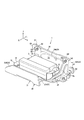
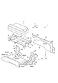
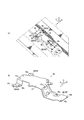
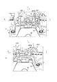
図1は本実施形態の車両用補機及びその配設構造を搭載した車両の車室の前方を示す平面図、図2は図1のA−A線矢視の要部における拡大断面図、図3は車両用補機およびその配設構造を後方左斜め上方から見た斜視図、図4は車両用補機およびその配設構造を前方右斜め上方から見た斜視図、図5は車両用補機およびその配設構造の平面図、図6は車両用補機およびその車両用補機の配設構造の分解斜視図、図7(a)は保護ブラケットの平面図、図7(b)は保護ブラケットの左側面図、図7(c)は保護ブラケットの前方から見た正面図、図8(a)は本実施形態の車両用補機の配設構造の周辺における車体側の構成の要部を示す斜視図、図8(b)は車両用補機の配設構造を取り付け支持する車体側のDCMブラケット台座部材の外観図である。
Hereinafter, embodiments of the present invention will be described in detail with reference to the drawings.
FIG. 1 is a plan view showing the front of a passenger compartment of a vehicle equipped with an auxiliary machine for a vehicle according to the present embodiment and its arrangement structure, and FIG. 2 is an enlarged cross-sectional view taken along the line AA in FIG. FIG. 3 is a perspective view of the vehicular auxiliary machine and its arrangement structure as seen from the rear left oblique upper side, FIG. 4 is a perspective view of the vehicular auxiliary machine and its arrangement structure as seen from the upper right oblique direction, and FIG. FIG. 6 is an exploded perspective view of the vehicle auxiliary machine and the vehicle auxiliary machine installation structure, FIG. 7A is a plan view of the protective bracket, and FIG. ) Is a left side view of the protective bracket, FIG. 7C is a front view seen from the front of the protective bracket, and FIG. 8A is a configuration on the vehicle body side in the vicinity of the arrangement structure of the auxiliary equipment for the vehicle of this embodiment. The perspective view which shows the principal part of FIG. 8, FIG.8 (b) is the DCM bracket base member of the vehicle body side which attaches and supports the arrangement | positioning structure of the auxiliary machine for vehicles. It is a watch view.
また図中、矢印Fは車両前方を示し、矢印Wは車幅方向を示し、矢印Rは車両右側を示し、矢印Lは車両左側を示し、矢印Uは車両上方を示すものとする。 In the figure, arrow F indicates the front of the vehicle, arrow W indicates the vehicle width direction, arrow R indicates the vehicle right side, arrow L indicates the vehicle left side, and arrow U indicates the vehicle upper side.
図1に示すように、車室下面は、不図示のダッシュロアパネルとリヤキックアップ部との間において前後方向に略水平に延びるフロアパネル100によって構成されており、このフロアパネル100の車幅方向の中央部には、図1、図2に示すように、上方(車室内方)に突出して車両の前後方向に延びるトンネル部101が形成されている。トンネル部101の上部には、該トンネル部101との間に閉断面を形成するトンネルメンバ102を接合している。このトンネルメンバ102は、トンネル部101の上部に沿って車両前後方向に延びる車体剛性部材である。なお、図2に示すように、トンネル部101の車外側の下部空間内には、エンジンの排気系部材の1つとして備えたエキゾーストパイプ103が配設されている。
As shown in FIG. 1, the lower surface of the passenger compartment is constituted by a
また図1に示すように、フロアパネル100の車幅方向両端部には、車両前後方向に延びる車体剛性部材としてのサイドシル104を接合している。
As shown in FIG. 1,
さらにフロアパネル100の前部には、フロントシート3が車幅方向に並んだ状態で設置され、このフロントシート3は、右ハンドル車においてトンネル部101に対して右側に配設された運転席3Rと、トンネル部101に対して左側に配設された助手席3Lから成る。
Further, the
すなわち、運転席3R及び助手席3Lは、それぞれシートクッション、シートバック3b、ヘッドレスト3cを有する左右独立のセパレートシートで構成されている。
なお、運転席3R及び助手席3Lは、略同じ構成であるため、一方のフロントシート3の構成に基づいて説明し、他方のフロントシート3についてはその説明を省略する。
That is, the driver's
Since the driver's
図2に示すように、フロントシート3の下部には、シートクッション3aシートバック3bおよびヘッドレスト3cを支持するシート支持構造4が設けられている。シート支持構造4は、フロアパネル100との間において車両前後方向に延び、シートクッション3aをシート前後方向(車両前後方向)に支持するためのスライド機構5が設けられている。このスライド機構5は、フロントシート3の車幅方向に左右一対備え(図2では一方のみ図示)、フロアパネル100に固定される左右一対のシートレール5aと、該シートレール5aに対してスライド可能に係合するスライダ5bとで主に構成されている。
As shown in FIG. 2, a seat support structure 4 that supports a
さらに、シート支持構造4は、スライド機構5のスライダ5bとシートクッション3aとの間に介在し、該シートクッション3aを支持する支持ブラケット6が左右各側に設けられている。
Further, the seat support structure 4 is interposed between the
そしてシート支持構造4には、これら左右の支持ブラケット6間には、車幅方向に直線状に延びるバー形状(パイプ形状)のシートクッションフレーム7が架設されており、該シートクッションフレーム7の車幅方向の両端部がそれぞれ対応する支持ブラケット6に溶接等により固定されている。
The seat support structure 4 is provided with a bar-shaped (pipe-shaped) seat cushion frame 7 extending linearly in the vehicle width direction between the left and
なお、上記のシートクッションフレーム7は、フロントシート3下部の剛性を高める強度部材として以外にも、リフタ機構(図示省略)に備えたリンク部材等を駆動するために左右一方に備えた駆動ユニット(図示省略)の駆動を他方に伝達するためのスタビライザとしての機能を適宜有してもよい。
The seat cushion frame 7 is not only a strength member that increases the rigidity of the lower portion of the
また、図1に示すように、車両の車室内前部には、車幅方向に延びるインストルメントパネル105(インパネ105)が配設されており、左右両フロントシート3(助手席3Lと運転席3R)間に、前後に延びるトンネルメンバ102を車室側(上方)から覆うようにインパネ105側から車体後方へ延出するセンタコンソール106が配設されている。なお、運転席3Rの前方にはステアリングホイール107が配設されている。
As shown in FIG. 1, an instrument panel 105 (instrument panel 105) extending in the vehicle width direction is disposed at the front of the vehicle interior of the vehicle, and both left and right front seats 3 (
図1に示すように、このセンタコンソール106にはシフトノブ108が設けられており、シフトノブ108は、後述するシフトノブ取付け用台座部材50(図8(a)参照)を介してトンネルメンバ102に取り付け支持されている。そしてシフトノブ108の後方部位には、DCMユニット1が配設されている。
図2に示すように、このDCMユニット1は、本実施形態の補機としてのDCM(Data
Communication Module)2と、DCMブラケット10,20とで構成され、車幅方向に並んだ助手席3Lと運転席3Rの間において、車室側(上方)からセンタコンソール106に覆われた状態で、車体側すなわち、DCMブラケット台座部材40を介してトンネルメンバ102に直接、又は間接的に取付け支持されている。
As shown in FIG. 1, the
As shown in FIG. 2, the
Communication Module) 2 and
ここで図8(a)、(b)に示すように、上記のDCMブラケット台座部材40は、台座部41と、該台座部41から下方かつ平面視で外側へ延びる複数のトンネルメンバ取付フランジ42(42f,42r)とで鋼板により一体に形成されている。複数のトンネルメンバ取付フランジ42のうち台座部41の後部から下方かつ後方へ延びる後側トンネルメンバ取付フランジ42rには、取付孔42aが貫通形成されており、該取付孔42aにおいてトンネルメンバ102にボルトB1及びナット(図示省略)を用いて締結固定されている。
Here, as shown in FIGS. 8A and 8B, the DCM
一方、複数のトンネルメンバ取付フランジ42のうち台座部41の前部から下方かつ左右各側へ延びる前側トンネルメンバ取付フランジ42fには、取付孔42aが貫通形成されており、該取付孔42aにおいてシフトノブ取付け用台座部材50にトンネルメンバ102へボルトB2及びナット(図示省略)を用いて締結固定されている。すなわち図8(a)に示すように、後側トンネルメンバ取付フランジ42rは、トンネルメンバ102に直接、締結固定されているのに対して、前側トンネルメンバ取付フランジ42fは、シフトノブ取付け用台座部材50を介してトンネルメンバ102に締結固定されている。
On the other hand, among the plurality of tunnel
同図に示すように、シフトノブ取付け用台座部材50は、その前側部位がDCMブラケット台座部材40よりも前方に位置するようにトンネルメンバ102の上面にボルトおよびナットにより締結固定されている。そして、シフトノブ取付け用台座部材50は、その後側部位に形成された後側台座面51rに、前側トンネルメンバ取付フランジ42fが取り付けられているとともに、その前側部位には、シフトノブ108が取り付けられる前側台座面51fが形成されている。
すなわち、シフトノブ取付け用台座部材50は、シフトノブ108だけでなくDCMブラケット台座部材40の前側部位の取り付けも兼ねている。
なお厳密にはシフトノブ108は、その前後各部位を2部材のブラケットにより、前後各側から支持されており、このうちシフトノブ108の後側部位を支持するブラケットがシフトノブ取付け用台座部材50に相当する。ただし当例では、シフトノブ108の前側部位を支持するブラケットは図示省略している。
As shown in the figure, the shift knob mounting
That is, the shift knob mounting
Strictly speaking, the front and rear portions of the
上記のDCM2は、車両から救助団体に情報を送信するための車載緊急通報装置であって、図2〜図6に示すように、全体がハウジングによって覆われており、車幅方向に対して車両前後方向に長い平面視略矩形状をした立体形状で構成されている。
The
そして図2に示すように、DCM2は、DCMブラケット10,20を介して車体側のDCMブラケット台座部材40に支持された車体側取り付け状態において、左右両フロントシート3R,3Lが並ぶ車幅方向の中間位置において、左右両側面がそれぞれに対応する側のフロントシート3R,3Lの下部に有するシートクッションフレーム7、特にシートクッション3aバーの車幅方向内側端部と車幅方向において対向する高さに配設されている。
As shown in FIG. 2, the
図2、図3、図5に示すように、DCM2の左右両側面のうち一方の側面、当例では左側(助手席3Lと対向する側)の側面(左側面)には、車体側から延びる電源や信号線用のハーネス61の一端側に有するハーネス側コネクタ61aを接続するDCM側コネクタ2aが設けられている。そして、ハーネス側コネクタ61aとDCM側コネクタ2aとの接続部分には、ハーネス接続部29が構成されている。
なお、幅方向よりも前後方向の長さが長いDCM2の前後長がさらに長くならないように、ハーネス接続部29はDCM2の左右両側面のうち一方の側面に構成している。
As shown in FIGS. 2, 3, and 5, one of the left and right side surfaces of the
Note that the
図2〜図6に示すように、DCMブラケット10,20は、主に、DCM2を固定するDCM固定ブラケット10と、車体側に取り付けられる保護ブラケット20の2部材とから構成されている。
As shown in FIGS. 2 to 6, the
保護ブラケット20は、図3〜図6に示すように、底面を構成するベース面22と、該ベース面22に対して車幅方向の両外端から該ベース面22に対して略直角に立設された左右各側の縦壁部23(23A,23B)と、左側の縦壁部23Aとベース面22との間に亘って形成されたリブ24と、が設けられている。
As shown in FIGS. 3 to 6, the
左右各側の縦壁部23は、車幅方向においてベース面22を隔てて互いに離間している。
そして図2、図4、図5に示すように、車両左側の縦壁部23A、すなわちハーネス接続部29に近い側の縦壁部23A(以下、「ハーネス側縦壁部23A」という。)は、車幅方向における助手席3LとDCM2との間に介在するようにベース面22に対して略直角に立設されている。このハーネス側縦壁部23Aは、右側の縦壁部23Bよりも高く形成されている。
The
2, 4, and 5, the
一方、右側の縦壁部23B、すなわち車幅方向においてハーネス接続部29と遠い側(車幅方向においてDCM2に対して縦壁部23Aと反対側)の縦壁部23B(以下、「非ハーネス側縦壁部23B」という。)は、車幅方向における運転席3RとDCM2との間に介在するようにベース面22に対して略直角に立設されている。
On the other hand, the
ここで、保護ブラケット20は、図6に示すように、主に、ベース面22および非ハーネス側縦壁部23Bを備えた保護ブラケット本体21と、ハーネス側縦壁部23Aを助手席3L側から正面視した形状に相当する板状の保護プレート28との2部材から成る。
Here, as shown in FIG. 6, the
保護ブラケット本体21のベース面22の左側端部には、その前後両端の各側から該ベース面22に対して略直角に立ち上がる前側立設部25fおよび後側立設部25rが設けられている。
The left end portion of the
そして、これら前側立設部25fおよび後側立設部25rと、上記の保護プレート28とでもって上記のハーネス側縦壁部23Aが形成される。
The harness side
図3〜図7に示すように、前側立設部25fは、その前縁の上下方向中間部から前方、左方、上方へこの順に屈曲しながら突出する前側係合突片31fが形成されており、後側立設部25rは、その後縁の上部から後方、左方、上方へこの順に屈曲しながら突出する後側係合突片31rが形成されている。一方、保護プレート28は、その前縁の上下方向中間部から前方、下方へこの順に屈曲しながら突出する前側被係合突片32fが形成されており、その後縁の上部から後方、下方へこの順に屈曲しながら突出する後側被係合突片32rが形成されている。
As shown in FIG. 3 to FIG. 7, the front-
そして、保護ブラケット20の前後各側において、前側立設部25fの前側係合突片31fと保護プレート28の前側被係合突片32fとを係合するとともに、後側立設部25rの後側係合突片31rと保護プレート28の後側被係合突片32rとを係合することで保護プレート28を保護ブラケット本体21に対して仮固定、すなわち取り外し可能に取り付けることができる。
Then, on each of the front and rear sides of the
また図6、図7(b)に示すように、保護ブラケット本体21は、前側立設部25fおよび後側立設部25rの各上部に、本体側取付け孔25a,25bが板厚方向(車幅方向)に貫通形成されているとともに、図6に示すように、保護プレート28は、その上部かつ前後各側の部位、すなわち、保護プレート28を保護ブラケット本体21に係合時に、本体側取付け孔25a,25bと対向する部位に、保護プレート側取付け孔28a,28bが板厚方向に貫通形成されている。
As shown in FIGS. 6 and 7 (b), the
そして、保護ブラケット本体21と保護プレート28とは、前後各側において、本体側取付け孔25a,25bと保護プレート側取付け孔28a,28bとにおいてボルトB3およびナットN3(図4、図5のみ図示)を用いて締結固定することができる。
The protective bracket
すなわち、本実施形態のDCMユニット1は、DCM2、DCM固定ブラケット10、及び保護ブラケット20の夫々を、一体に組み付けた(アッセンブリした)うえで車体側に取り付けられるが、その際、保護プレート28を取り付けていない状態で車体側に取付け、ハーネス側コネクタ61aをDCM側コネクタ2aに接続した後で、上述したように保護プレート28を、保護ブラケット本体21に対して仮固定したうえでボルトB3およびナットN3を用いて取り付けられる。
That is, the
これによりDCMユニット1の左側面にハーネス側縦壁部23Aを構成することができ、該ハーネス側縦壁部23Aを、図2に示すように、車幅方向において、助手席3LとDCM2との間に介在させることができる。
Thereby, the harness side
図4、図6に示すように、保護ブラケット20の面には、前後方向の中央部から下端部にかけての部位が、該部位の外周部位よりも板厚方向の一方側(当例では左側)へ膨出する膨出部33が形成されており、この膨出部33の下端を除く周縁には、該膨出部33の稜線を形成するビード34が形成されている。このビード34には、車両前後方向に沿って延びる前後方向ビード34aを備えている。
As shown in FIGS. 4 and 6, on the surface of the
前後方向ビード34aには、側突時において助手席3Lのシートクッション3aの一部が当接することに対して保護ブラケット20の強度を高める補強部である。
The front-
図4〜図7(a)、(b)、(c)に示すように、上記のリブ24は、車両前後方向に間隔を隔てて並設されており、これらリブ24(前側リブ24および後側リブ24)は、共に前側立設部25fとベース面22とのコーナー部(内側コーナー部)において、これらの間に亘って形成されるとともに、車幅方向かつ上下方向に平行な面24s、すなわち前後方向に垂直な面24sを有して互いに同一形状で形成されている。
As shown in FIGS. 4 to 7A, 7B, and 7C, the
具体的にリブ24は、ベース面22の前部22f(ベース面前部22f)の車幅方向の全長に亘って該前部22fの上面に対して上方に突出するとともに、その車両左側部位が前側立設部25fの本体側取付け孔25aに至る手前まで前側立設部25fの右面(車幅方向内面)に対して車両右方へ突出して、車両前方から後方視で略逆L字形状に形成されている(図2参照)。
Specifically, the
なお、後側立設部25rには、ベース面22とのコーナー部を含めて上下に延びるビード35が設けられている(図4、図6参照)。
In addition, the rear
さらに図6、図7(a)、(b)、(c)に示すように、保護ブラケット本体21における、ベース面22の前後方向の中間部には、前後各部位(ベース面前部22f及びベース面後部22r)の上面に対して隆起する台座部26が形成されており、この台座部26の上面には、DCM固定ブラケット10を配置可能な平坦状の台座面26aが形成されている。
Furthermore, as shown in FIGS. 6, 7A, 7B, and 7C, in the middle portion of the
図6、図7(a)に示すように、台座部41の左側部位であって、該台座部41の車幅方向における前後各側の立設部25f,25rよりも内側に相当する部位には、ハーネス接続部29(ハーネス側コネクタ61a)から延びるハーネス61を下方へと配索可能とするハーネス配索空間Zが切欠き状に形成されている。
As shown in FIG. 6 and FIG. 7A, the left portion of the
台座部41の前後各側の縁辺には、ベース面22の前部に対して段状に隆起する段部27が形成されている。これら段部27(前側段部27f、後側段部27r)は、共に車幅方向に直線状に延びており、このうち後側段部27rは、非ハーネス側縦壁部23Bとハーネス側縦壁部23A(後側立設部25r)とを連結するように車幅方向に延びている。
A stepped
また図6、図7(a)に示すように、ベース面後部22rの後部において車幅方向に離間した2つの部位、およびベース面前部22fのリブ24よりも前側部位の合計3つの部位、すなわち図8(a)、(b)に示す上記DCMブラケット台座部材40の台座部41に設けた取付け孔41aと対応させた部位には、取付け孔22aが貫通形成されている。
Further, as shown in FIGS. 6 and 7A, there are a total of three parts including two parts spaced apart in the vehicle width direction at the rear part of the base surface
そして、DCM固定ブラケット10をDCMブラケット台座部材40の台座部41に配置した状態において、ボルトB4(図5参照)およびナット(図示省略)を用いて取付け孔41aおよび取付け孔22aにおいて締結固定することで、保護ブラケット20を車体側のDCMブラケット台座部材40に取り付けることができる。
Then, in a state in which the
図6に示すように、上記のDCM固定ブラケット10は、平面視略矩形状に形成されたDCM固定ブラケット本体部11の外周側においてDCM2を取り付けるDCM取付用台座部11Aと、DCM固定ブラケット10を保護ブラケット20の台座面26aに設置する設置部11Bと、DCM2の前側に配置される図外のアース端子を接続固定するための前側アース用フランジ部12と、DCM固定ブラケット本体部11に対して後方へ延設する後方延設部13と、DCM2の後側に配置される図外のアース端子を接続固定するための後側アース用フランジ部14と、DCM2近傍に位置し、DCM2以外の図外の補機に接続されるハーネス(図示省略)を固定するためのクリップ取付用フランジ部15と、で一体に形成されている。
As shown in FIG. 6, the
DCM取付用台座部11Aは、平坦状に形成され、その4隅の部位にDCM2をボルトおよびナットを用いて締結固定する取付け孔11aが貫通形成されている。
なお、図7(a)に示すように、平面視で取付け孔11aに対応させて保護ブラケット20のベース面後部22rに設けた貫通孔22bは、DCM2をDCM取付用台座部11Aに取り付け時に用いる上記ボルト(図示省略)挿通用のサービスホールである。
The DCM mounting
In addition, as shown to Fig.7 (a), the through-
なお図6に示すように、設置部11Bは、DCM固定ブラケット本体部11の中央部においてDCM取付用台座部11Aに対して下方へ凹状に形成され、その下面(底面)は、保護ブラケット20の台座面26aと面接触状態で当接可能に平坦状に形成されている。
As shown in FIG. 6, the
前側アース用フランジ部12は、DCM固定ブラケット本体部11の前端から該DCM取付用台座部11Aに対して直角に立設するとともに、その上端から後方へ水平に延設されている。
The front-side
後方延設部13は、保護ブラケット20におけるベース面後部22rの上方に配置され、且つ図5に示すように、平面視で取付け孔22a(図7(a)参照)を迂回するようにDCM固定ブラケット本体部11の後端から後方へ水平に延設されている。
The
後側アース用フランジ部14およびクリップ取付用フランジ部15は、図5に示すように、後方延設部13からさらに後方、後方斜め左側のそれぞれの側へ水平に延設されている。
As shown in FIG. 5, the rear
上述したDCM固定ブラケット10は、側突時に車体側からダイレクトに側突荷重が伝わらないように車体側、すなわちDCMブラケット台座部材40(図8(a)、(b)参照)に対して、保護ブラケット20を介してのみ固定されており、これにより、DCM固定ブラケット10は、保護ブラケット20が変形した際に、該保護ブラケット20に対して相対変位可能に構成されている(図2参照)。
The above-described
具体的には、DCM固定ブラケット10の設置部11Bの下面を、保護ブラケット20の台座面26aに面接触した状態で当接するとともに、この当接部位において互いに溶接されている。
Specifically, the lower surface of the
その一方でDCM固定ブラケット10と保護ブラケット20とは、設置部11Bの下面と台座面26aとを溶接することのみによって固定されており、DCM固定ブラケット10は、この溶接箇所Aを除いてDCM固定ブラケット10は勿論、車体側に対しても固定されていない。
On the other hand, the
これにより、DCM固定ブラケット10は、その設置部11Bの下面が側突時に保護ブラケット20の台座面26aに対して剥離することによって、該保護ブラケット20に対して相対変位可能に構成されている。
Accordingly, the
続いて、車幅方向におけるDCM2に対してハーネス接続部29が位置する車両左側からの側面衝突時(側突時)の初期、中期、後期の各段階における本実施形態のDCMユニット1が奏する作用について図9(a)、(b)、図10を用いて説明する。図9(a)は側突初期の状態を図2に対応して示した作用説明図、図9(b)は側突中期の状態を図2に対応して示した作用説明図、図10は側突後期の状態を図2に対応して示した作用説明図である。
Subsequently, the
まず、側突初期においては、車両左側からの荷重入力に伴って、図2に示す状態から図9(a)に示すように、助手席3Lのシート支持構造4は、シートレール5aがフロアパネル100から外れたり、該シート支持構造4自体が変形する等して車幅方向内側、すなわちDCMユニット1側に向けて変位する。
First, in the initial stage of the side collision, as shown in FIG. 9 (a) from the state shown in FIG. 2 in accordance with load input from the left side of the vehicle, the seat support structure 4 of the
側突中期においては、図9(b)に示すように、車幅方向内側へ変位する助手席3Lのシート支持構造4の特に、バー形状のシートクッションフレーム7の車幅方向の内端がハーネス側縦壁部23Aにダイレクトに当接する。
In the middle side collision, as shown in FIG. 9 (b), the inner end in the vehicle width direction of the bar-shaped seat cushion frame 7 of the seat support structure 4 of the
ここで、ハーネス側縦壁部23AがDCM2の側へ倒れ込まないようにリブ24によって受け止めるとともに、該ハーネス側縦壁部23A(保護プレート28)は、それ自体が変形しないように前後方向ビード34aによって補強されているため(図6参照)、助手席3Lのシート支持構造4からの側突荷重をしっかりと受け止めることができる。
Here, the harness-side
これにより、たとえ図9(b)に示すように、非ハーネス側縦壁部23Bが運転席3Rのシート支持構造4に当接したり、DCMブラケット台座部材40が大きく変形しても、保護ブラケット20すなわち、ベース面22と一対の縦壁部23A,23Bによって構成されるDCM2の配設空間が潰れることがなく、DCM2が助手席3Lのシート支持構造4から側突荷重をダイレクトに受けることを阻止することができる。
Accordingly, as shown in FIG. 9B, even if the non-harness side
側突後期においては図10に示すように、車体側(例えば、DCMブラケット台座部材40側)から保護ブラケット20を介して、DCM固定ブラケット10側へ伝達される荷重がある程度大きくなると、保護ブラケット本体21の台座部26とDCM固定ブラケット10の設置部11Bとの溶着箇所A(図2参照)においてDCM固定ブラケット10が保護ブラケット20に対して剥離することでDCM2と一体に浮き上がるようにして変位させことができる(図10中の太矢印参照)。
As shown in FIG. 10, when the load transmitted from the vehicle body side (for example, the DCM
上述した本実施形態のDCMユニット1は、車体における、車幅方向に並んだフロントシート3R,3Lの間に補機としてのDCM2を配設する車両用補機の配設構造であって、DCM2が取り付けられるとともに車体に固定されるDCMブラケット10,20を有し、DCM2は、ハーネス61が接続されるハーネス接続部29を有するとともに該ハーネス接続部29が一方のフロントシート3L(助手席3L)側に位置するように配置され、DCMブラケット10,20のうち保護ブラケット20には、ベース面22と、DCM2と各フロントシート3(3R,3L)の間に、車幅方向に互いに離間するようにベース面22に対して立設された一対の縦壁部23(23A,23B)と、該一対の縦壁部23A,23BのうちDCM2のハーネス接続部29に近い側のハーネス側縦壁部23Aにおいて、該ハーネス側縦壁部23Aとベース面22との間に亘るリブ24と、が形成されたものである(図2〜図7(a)、(c)参照)。
The above-described
上記構成によれば、側突時にDCM2が助手席3Lと直接的に干渉する可能性を低減することができる。詳しくは、側突時にハーネス側縦壁部23AがDCM2の側へ倒れ込まないようにハーネス側縦壁部23Aをリブ24によって支持することができるため、ハーネス側縦壁部23Aをリブ24で支持しない場合よりもハーネス接続部29をより確実に保護することができる。したがって、側突時に助手席3Lの一部(例えば、シートクッションフレーム7)がハーネス側縦壁部23Aに当接してもDCM2を機能させることができる。
According to the above configuration, it is possible to reduce the possibility that the
この発明の態様として、リブ24は、車幅方向に平行な面24sから形成されたものである(図2〜図4、図6、図7(c)参照)。
As an aspect of the present invention, the
上記構成によれば、側突時に助手席3Lの一部がハーネス側縦壁部23Aに当接しても車幅方向に平行な面24sから形成されたリブ24によって、該ハーネス側縦壁部23Aの倒れ込みをより確実に防止できる。
According to the above configuration, the harness-side
またこの発明の態様として、ハーネス側縦壁部23Aは、DCM固定ブラケット10や保護ブラケット本体21とは別部材で且つ、該保護ブラケット本体21に対して着脱可能な保護プレート28で形成されたものである(図3〜図6参照)。
Further, as an aspect of the present invention, the harness side
上記構成によれば、保護ブラケット本体21から保護プレート28を取り外すことで、ハーネス接続部29は該保護プレート28によって左側方から覆われずに開放できるため、ハーネス61をDCM2に接続する際に保護プレート28が邪魔になることなく適切かつ容易に接続することができつつ、車両走行時(通常時)に保護ブラケット本体21に保護プレート28を取り付けておくことで、側突時に助手席3Lの一部がDCM2の側に変位しても保護プレート28に当接することによってハーネス接続部29を保護することができる。
According to the above configuration, by removing the
またこの発明の態様として、ハーネス側縦壁部23Aには、車両前後方向に沿って延びる補強部としての前後方向ビード34aが形成されたものである(図4、図6参照)。
As an aspect of the present invention, the harness-side
上記構成によれば、ハーネス側縦壁部23Aに補強部としての前後方向ビード34aを形成することによって、側突時に助手席3Lの一部への当接に対するハーネス側縦壁部23Aの強度を高めることができ、該ハーネス側縦壁部23Aによるハーネス接続部29の保護性能を高めることができる。
According to the above-described configuration, the strength of the harness-side
またこの発明の態様として、ベース面22には、該ベース面22に対して隆起する台座部26が構成されており、台座部26の端辺には、車幅方向に延びる段部27(27f、27r)が設けられたものである(図3、図5〜図7(a)、(b)、(c)参照)。
Further, as an aspect of the present invention, the
上記構成によれば、車幅方向に延びる段部27を端辺に有する台座部26によってベース面22の車幅方向の圧縮強度を高めることができるため、側突時にベース面22が車幅方向に潰れて両縦壁部23の間の間隔が狭まることがないように該ベース面22の形状を保持することができ、もってDCM2が破損しないように保護することができる。
According to the above configuration, the compressive strength in the vehicle width direction of the
すなわち、リブ24を設けてハーネス側縦壁部23Aを補強することによってもベース面22が相対的に脆弱化することがなく、段部27によってベース面22についても補強することでるため、側突時に対して縦壁部23とベース面22とでDCM2を保護することができる。
That is, the
この発明は、上述の実施例の構成のみに限定されるものではなく様々な実施形態で形成することができる。
例えば、本発明のハーネス接続部29は、右側(運転席3R側)に設けてもよい。すなわち、ハーネス側縦壁部23Aと非ハーネス側縦壁部23Bを左右逆に設けてもよい。
The present invention is not limited to the configuration of the above-described embodiment, and can be formed in various embodiments.
For example, the
また本発明の車両用補機の配設構造は、車幅方向に並ぶフロントシート間に補機を配設する構造に限らず、例えば、車幅方向に並ぶリヤシート間に補機を配設する構造に適用してもよい。 Further, the arrangement structure of the auxiliary machine for a vehicle according to the present invention is not limited to the structure in which the auxiliary machine is arranged between the front seats arranged in the vehicle width direction. For example, the auxiliary machine is arranged between the rear seats arranged in the vehicle width direction. It may be applied to the structure.
1…DCMユニット(車両用補機の配設構造)
2…DCM(補機)
3(3R,3L)…フロントシート(シート)
10,20…DCMブラケット(ブラケット)
22…ベース面
23(23A,23B)…一対の縦壁部
23L…助手席(一方のシート)
23A…ハーネス側縦壁部
24…リブ
24s…車幅方向に平行な面
26…台座部
27(27f,27r)…段部
28…保護プレート
29…ハーネス接続部
34a…前後方向ビード(補強部)
61…ハーネス
1 ... DCM unit (arrangement structure of auxiliary equipment for vehicles)
2 ... DCM (auxiliary machine)
3 (3R, 3L) ... Front seat (seat)
10, 20 ... DCM bracket (bracket)
22 ... Base surface 23 (23A, 23B) ... Pair of vertical wall portions 23L ... Passenger seat (one seat)
23A ... Harness side
61 ... harness
Claims (5)
上記補機が取り付けられるとともに車体に固定されるブラケットを有し、
上記補機は、ハーネスが接続されるハーネス接続部を有するとともに該ハーネス接続部が一方のシート側に位置するように配置され、
上記ブラケットには、ベース面と、上記補機と各シートの間に、車幅方向に互いに離間するように上記ベース面に対して立設された一対の縦壁部と、該一対の縦壁部のうち上記補機の上記ハーネス接続部に近い側のハーネス側縦壁部において、該ハーネス側縦壁部と上記ベース面との間に亘るリブと、が形成された
車両用補機の配設構造。 A vehicle auxiliary machine arrangement structure in which an auxiliary machine is arranged between seats arranged in the vehicle width direction in a vehicle body,
A bracket to which the auxiliary machine is attached and fixed to the vehicle body;
The auxiliary machine has a harness connection part to which a harness is connected and is arranged so that the harness connection part is located on one seat side,
The bracket includes a base surface, a pair of vertical wall portions erected with respect to the base surface so as to be separated from each other in the vehicle width direction between the auxiliary machine and each seat, and the pair of vertical walls Of the auxiliary equipment for a vehicle in which a rib extending between the harness-side vertical wall portion and the base surface is formed in the harness-side vertical wall portion of the auxiliary equipment close to the harness connecting portion. Construction structure.
請求項1に記載の車両用補機の配設構造。 2. The vehicle auxiliary machine disposition structure according to claim 1, wherein the rib is formed from a surface parallel to the vehicle width direction.
請求項1又は2に記載の車両用補機の配設構造。 The arrangement structure of a vehicular auxiliary machine according to claim 1 or 2, wherein the harness-side vertical wall portion is a member separate from the bracket and formed of a protective plate that can be attached to and detached from the bracket.
請求項1乃至3のいずれか1項に記載の車両用補機の配設構造。 The arrangement structure of the auxiliary equipment for vehicles according to any one of claims 1 to 3, wherein a reinforcing portion extending along the vehicle front-rear direction is formed on the harness-side vertical wall portion.
上記台座部の端辺には、車幅方向に延びる段部が設けられた
請求項1乃至4のいずれか1項に記載の車両用補機の配設構造。 The base surface is configured with a pedestal that rises with respect to the base surface.
The arrangement structure of the auxiliary equipment for vehicles of any one of Claims 1 thru | or 4 by which the step part extended in a vehicle width direction was provided in the edge side of the said base part.
Priority Applications (6)
| Application Number | Priority Date | Filing Date | Title |
|---|---|---|---|
| JP2017030639A JP6380574B2 (en) | 2017-02-22 | 2017-02-22 | Arrangement structure of auxiliary equipment for vehicle |
| PCT/JP2018/003889 WO2018155152A1 (en) | 2017-02-22 | 2018-02-06 | Arrangement structure of accessory for vehicle |
| EP18757666.5A EP3572289B1 (en) | 2017-02-22 | 2018-02-06 | Arrangement structure of auxiliary machine for vehicle |
| CN201880012945.1A CN110325404B (en) | 2017-02-22 | 2018-02-06 | Mounting structure of vehicle accessory device |
| US16/486,978 US11491922B2 (en) | 2017-02-22 | 2018-02-06 | Arrangement structure of auxiliary machine for vehicle |
| RU2019128446A RU2720587C1 (en) | 2017-02-22 | 2018-02-06 | Placed design of auxiliary device for a vehicle |
Applications Claiming Priority (1)
| Application Number | Priority Date | Filing Date | Title |
|---|---|---|---|
| JP2017030639A JP6380574B2 (en) | 2017-02-22 | 2017-02-22 | Arrangement structure of auxiliary equipment for vehicle |
Publications (2)
| Publication Number | Publication Date |
|---|---|
| JP6380574B2 true JP6380574B2 (en) | 2018-08-29 |
| JP2018134973A JP2018134973A (en) | 2018-08-30 |
Family
ID=63254286
Family Applications (1)
| Application Number | Title | Priority Date | Filing Date |
|---|---|---|---|
| JP2017030639A Active JP6380574B2 (en) | 2017-02-22 | 2017-02-22 | Arrangement structure of auxiliary equipment for vehicle |
Country Status (6)
| Country | Link |
|---|---|
| US (1) | US11491922B2 (en) |
| EP (1) | EP3572289B1 (en) |
| JP (1) | JP6380574B2 (en) |
| CN (1) | CN110325404B (en) |
| RU (1) | RU2720587C1 (en) |
| WO (1) | WO2018155152A1 (en) |
Family Cites Families (23)
| Publication number | Priority date | Publication date | Assignee | Title |
|---|---|---|---|---|
| JP3726277B2 (en) * | 1997-01-30 | 2005-12-14 | マツダ株式会社 | Airbag system for vehicles |
| US6663411B2 (en) | 1998-07-15 | 2003-12-16 | Tyco Electronics Logistics Ag | Clamshell connector for airbag gas generator |
| DE69936207T2 (en) * | 1998-07-15 | 2008-01-24 | Thomas & Betts International Inc., Sparks | CONNECTOR FOR AIRBAG GAS GENERATOR |
| JP4306396B2 (en) * | 2003-10-06 | 2009-07-29 | 株式会社デンソー | Airbag ECU |
| JP2005238990A (en) * | 2004-02-26 | 2005-09-08 | Denso Corp | Acceleration sensor mounting structure |
| JP4752432B2 (en) * | 2005-10-03 | 2011-08-17 | 日産自動車株式会社 | Unit mounting structure |
| JP4367504B2 (en) | 2007-03-06 | 2009-11-18 | 株式会社デンソー | In-vehicle emergency call device |
| JP4640431B2 (en) | 2008-03-26 | 2011-03-02 | トヨタ自動車株式会社 | Collision detection structure and occupant protection system |
| WO2009118609A1 (en) | 2008-03-26 | 2009-10-01 | Toyota Jidosha Kabushiki Kaisha | Impact detection structure, impact detection system and method, and occupant protection system and method |
| DE102008040157A1 (en) * | 2008-07-03 | 2010-01-07 | Robert Bosch Gmbh | Personal protective device for a vehicle or method for assembling such a control device |
| DE112009004801B4 (en) * | 2009-05-28 | 2018-08-30 | Toyota Jidosha Kabushiki Kaisha | FUEL CELL SYSTEM AND VEHICLE |
| JP5077611B2 (en) * | 2009-05-28 | 2012-11-21 | トヨタ自動車株式会社 | Fuel cell system and vehicle |
| JP4924665B2 (en) * | 2009-06-11 | 2012-04-25 | 日産自動車株式会社 | Rear structure of the car body |
| US9033399B2 (en) * | 2010-03-01 | 2015-05-19 | Sabic Global Technologies B.V. | Energy absorber elements and vehicle systems |
| IN2014CN02886A (en) * | 2011-10-24 | 2015-07-03 | Honda Motor Co Ltd | |
| JP2013119326A (en) * | 2011-12-07 | 2013-06-17 | Honda Motor Co Ltd | Protective structure of electrical component |
| GB2500599B (en) * | 2012-03-26 | 2017-08-16 | Ford Global Tech Llc | Vehicle seat assembly |
| WO2017002191A1 (en) * | 2015-06-30 | 2017-01-05 | 本田技研工業株式会社 | Electronic control unit bracket and vehicle |
| JP6350585B2 (en) * | 2016-04-22 | 2018-07-04 | マツダ株式会社 | Emergency call device installation structure |
| US10150440B2 (en) * | 2016-05-19 | 2018-12-11 | Ford Global Technologies, Llc | Restraints control module attachment assembly |
| JP6702061B2 (en) * | 2016-07-28 | 2020-05-27 | 三菱自動車工業株式会社 | Car body structure |
| CN106891906B (en) * | 2017-03-22 | 2018-12-11 | 青岛欧特美交通装备有限公司 | A kind of single piece type side guard plate device with vertical pooling feature |
| US11027680B2 (en) * | 2018-12-13 | 2021-06-08 | Ford Global Technologies, Llc | Vehicle tracks |
-
2017
- 2017-02-22 JP JP2017030639A patent/JP6380574B2/en active Active
-
2018
- 2018-02-06 CN CN201880012945.1A patent/CN110325404B/en active Active
- 2018-02-06 EP EP18757666.5A patent/EP3572289B1/en active Active
- 2018-02-06 WO PCT/JP2018/003889 patent/WO2018155152A1/en unknown
- 2018-02-06 RU RU2019128446A patent/RU2720587C1/en active
- 2018-02-06 US US16/486,978 patent/US11491922B2/en active Active
Also Published As
| Publication number | Publication date |
|---|---|
| CN110325404A (en) | 2019-10-11 |
| RU2720587C1 (en) | 2020-05-12 |
| US11491922B2 (en) | 2022-11-08 |
| WO2018155152A1 (en) | 2018-08-30 |
| US20200231098A1 (en) | 2020-07-23 |
| JP2018134973A (en) | 2018-08-30 |
| EP3572289A1 (en) | 2019-11-27 |
| CN110325404B (en) | 2021-12-21 |
| EP3572289B1 (en) | 2021-05-05 |
| EP3572289A4 (en) | 2019-12-04 |
Similar Documents
| Publication | Publication Date | Title |
|---|---|---|
| EP2045170B1 (en) | Front end structure for automobile | |
| EP1749731B1 (en) | Vehicle rear body structure of an automotive vehicle and mounting method therefor | |
| JP5029135B2 (en) | Car side body structure | |
| US7631926B2 (en) | Side impact crash event body structure improvement | |
| JP4919144B2 (en) | Step mounting structure for getting on and off the vehicle | |
| JP2008222185A (en) | Front body structure of vehicle | |
| CN112441125B (en) | Vehicle body front structure | |
| JP3930004B2 (en) | Sensor arrangement structure | |
| JP5353364B2 (en) | Lower body structure of the vehicle | |
| JP4438416B2 (en) | Front body structure of the vehicle | |
| JP2021075089A (en) | Vehicle lower part structure | |
| JP6551435B2 (en) | Arrangement structure of vehicle accessories | |
| JP4635467B2 (en) | Vehicle collision detection sensor arrangement structure | |
| JP6380574B2 (en) | Arrangement structure of auxiliary equipment for vehicle | |
| JP5852623B2 (en) | Body structure | |
| JP4894613B2 (en) | Bumper mounting structure for vehicles | |
| JP2004330863A (en) | Vehicular roof structure | |
| JP2008302911A (en) | Vehicle body structure | |
| JP4154698B2 (en) | Rear side structure of vehicle | |
| JP3497394B2 (en) | Mounting structure of collision detection sensor | |
| CN114537536A (en) | Vehicle body structure | |
| JP2014213764A (en) | Vehicle body front part structure | |
| CN114571974A (en) | Battery support structure | |
| US20220402557A1 (en) | Vehicle front portion structure | |
| WO2023175843A1 (en) | Vehicle body front part structure |
Legal Events
| Date | Code | Title | Description |
|---|---|---|---|
| A871 | Explanation of circumstances concerning accelerated examination |
Free format text: JAPANESE INTERMEDIATE CODE: A871 Effective date: 20180620 |
|
| TRDD | Decision of grant or rejection written | ||
| A975 | Report on accelerated examination |
Free format text: JAPANESE INTERMEDIATE CODE: A971005 Effective date: 20180628 |
|
| A01 | Written decision to grant a patent or to grant a registration (utility model) |
Free format text: JAPANESE INTERMEDIATE CODE: A01 Effective date: 20180703 |
|
| A61 | First payment of annual fees (during grant procedure) |
Free format text: JAPANESE INTERMEDIATE CODE: A61 Effective date: 20180716 |
|
| R150 | Certificate of patent or registration of utility model |
Ref document number: 6380574 Country of ref document: JP Free format text: JAPANESE INTERMEDIATE CODE: R150 |