以下図面を参照して、本開示における典型的な実施形態の一つについて説明する。なお、以降の説明では、眼内レンズ挿入器具収容用のケース30をケース30と称する。また、ケース30と、ケース30に収容された眼内レンズ挿入器具10とを眼内レンズ挿入システム40と称する。また、眼内レンズ挿入器具10が使用された際に、眼内レンズ挿入器具10内に充填された眼内レンズ1が押し出される方向を押出軸Aと称する。
Hereinafter, one exemplary embodiment of the present disclosure will be described with reference to the drawings. In the following description, the case 30 for housing the intraocular lens insertion instrument is referred to as the case 30. The case 30 and the intraocular lens insertion device 10 housed in the case 30 are referred to as an intraocular lens insertion system 40. The direction in which the intraocular lens 1 filled in the intraocular lens insertion device 10 is pushed out when the intraocular lens insertion device 10 is used is referred to as an extrusion axis A.
また、ケース30に眼内レンズ挿入器具10が収容された状態において、眼内レンズ挿入器具10のベベル部113(図3参照)の開口端面が向く方向を「方向X」又は「左方」ということとする。また、ケース30にシート80が貼り付けられる方向を「方向Y」又は「下方」ということとする。また、ケース30に眼内レンズ挿入器具10が収容された状態において、眼内レンズ挿入器具10のノズル部112(図3参照)が向く方向を「方向Z」又は「前方(先端側)」ということとする。
<1−1.全体構成>
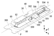
図1は本実施形態の眼内レンズ挿入システム40を斜め上方からみた斜視図である。なお、図1は説明図であり、ケース本体70への支持部材50の装着状態、及び支持部材50による眼内レンズ挿入器具10の支持状態を説明するために、ケース本体70の一部を削り取った説明用の斜視図としている。
Further, in a state where the intraocular lens insertion device 10 is accommodated in the case 30, the direction in which the opening end surface of the bevel portion 113 (see FIG. 3) of the intraocular lens insertion device 10 faces is referred to as “direction X” or “left”. I will do it. The direction in which the sheet 80 is attached to the case 30 is referred to as “direction Y” or “downward”. Further, in a state where the intraocular lens insertion device 10 is accommodated in the case 30, the direction in which the nozzle portion 112 (see FIG. 3) of the intraocular lens insertion device 10 faces is referred to as “direction Z” or “front (front end side)”. I will do it.
<1-1. Overall configuration>
FIG. 1 is a perspective view of the intraocular lens insertion system 40 of the present embodiment as viewed obliquely from above. FIG. 1 is an explanatory diagram, and in order to explain the mounting state of the support member 50 to the case body 70 and the support state of the intraocular lens insertion device 10 by the support member 50, a part of the case body 70 is scraped off. It is a perspective view for explanation.
本実施形態の眼内レンズ挿入システム40は、ケース30と眼内レンズ挿入器具10を備える。また、ケース30は、ケース本体70と支持部材50を備える。なお、本実施形態のケース30のケース本体70は、シートを変形させる加工方法によって形成されている。ケース本体70には、眼内レンズ挿入器具10全体を収容できる凹凸部60が形成されている。なお、本実施形態のケース30には、凹凸部60によって形成される空間部の少なくとも一部を塞ぐシート80が、ケース30の底面の鍔部300に貼り付けられる(シート80に関しては図10も参考されたし)。凹凸部60によって形成される空間部には、眼内レンズ挿入器具10が収容される。また、眼内レンズ挿入システム40は紙箱81に収容される(紙箱81に関しては図11参照)。また、ケース本体70の上方外側面にはシール82が貼り付けられる。シール82は、製造された眼内レンズ挿入システム40の識別用として用いられる。シール82には、ケース30に収容される眼内レンズ挿入器具10の種類を示す文字のほか、眼内レンズ挿入器具10に充填される眼内レンズ1の屈折度数等が表記される。
<1−2.眼内レンズ挿入器具>
The intraocular lens insertion system 40 of this embodiment includes a case 30 and an intraocular lens insertion instrument 10. The case 30 includes a case main body 70 and a support member 50. In addition, the case main body 70 of the case 30 of this embodiment is formed by the processing method which deform | transforms a sheet | seat. The case body 70 is formed with an uneven portion 60 that can accommodate the entire intraocular lens insertion device 10. In addition, in the case 30 of the present embodiment, a sheet 80 that covers at least a part of the space formed by the concavo-convex portion 60 is attached to the flange portion 300 on the bottom surface of the case 30 (see FIG. 10 for the sheet 80 as well). It was helpful) The intraocular lens insertion device 10 is accommodated in the space formed by the uneven portion 60. The intraocular lens insertion system 40 is accommodated in a paper box 81 (see FIG. 11 for the paper box 81). A seal 82 is attached to the upper outer surface of the case body 70. The seal 82 is used for identification of the manufactured intraocular lens insertion system 40. In addition to characters indicating the type of the intraocular lens insertion device 10 accommodated in the case 30, the seal 82 indicates the refractive power of the intraocular lens 1 filled in the intraocular lens insertion device 10.
<1-2. Intraocular lens insertion device>
図1〜3を用いて本実施形態の眼内レンズ挿入器具10を説明する。本実施形態の眼内レンズ挿入器具10は、製造時に眼内レンズ1を充填(セット)しておくプリセット型の眼内レンズ挿入器具10とされている。製造時に眼内レンズ1を充填しておくことで、使用現場で眼内レンズ1を充填する作業が不要となり、使用現場で眼内レンズ1を速やかに患者眼の眼内へ挿入することができる。なお、本実施形態の眼内レンズ挿入器具10は樹脂材料で形成されている。眼内レンズ挿入器具10が樹脂材料で形成されているため、金属で成形する場合に対して、使用者に眼内レンズ挿入器具10を安価に提供することができる。また、使用者は、眼内レンズ1を眼内に挿入した後に、眼内レンズ挿入器具10を容易に廃棄することができる。眼内レンズ挿入器具10を容易に廃棄できるため、使用毎の眼内レンズ挿入器具10の滅菌処理が不要となり、眼内レンズ挿入器具10を容易に取り扱うことができる。なお、眼内レンズ挿入器具10は樹脂材料を用いた射出成形(モールド成型)、樹脂の削り出しによる切削加工などで成形されればよい。なお、眼内レンズ挿入器具10に金属材料を使用してもよいことは言うまでもない。また、本実施形態の眼内レンズ挿入器具10を再利用してもよい。
The intraocular lens insertion device 10 of the present embodiment will be described with reference to FIGS. The intraocular lens insertion device 10 of the present embodiment is a preset type intraocular lens insertion device 10 in which the intraocular lens 1 is filled (set) at the time of manufacture. By filling the intraocular lens 1 at the time of manufacture, the work of filling the intraocular lens 1 at the site of use becomes unnecessary, and the intraocular lens 1 can be quickly inserted into the eye of the patient's eye at the site of use. . Note that the intraocular lens insertion device 10 of the present embodiment is formed of a resin material. Since the intraocular lens insertion device 10 is formed of a resin material, the intraocular lens insertion device 10 can be provided to the user at a low cost as compared with the case of molding with metal. Further, the user can easily discard the intraocular lens insertion device 10 after inserting the intraocular lens 1 into the eye. Since the intraocular lens insertion device 10 can be easily discarded, the sterilization process of the intraocular lens insertion device 10 for each use becomes unnecessary, and the intraocular lens insertion device 10 can be handled easily. The intraocular lens insertion device 10 may be formed by injection molding (molding) using a resin material, cutting by resin cutting, or the like. Needless to say, a metal material may be used for the intraocular lens insertion device 10. Moreover, you may reuse the intraocular lens insertion instrument 10 of this embodiment.
本実施形態の眼内レンズ挿入器具10は、筒状の挿入器具本体100と棒状のプランジャー200を備える。挿入器具本体100は本体筒部130、張り出し部190、設置部120、保持部121、可動部材122、及び挿入部110を備える。なお、本実施形態の眼内レンズ挿入器具10に使用する眼内レンズ1は、折り畳むことが可能な軟性眼内レンズとされている。
The intraocular lens insertion device 10 of the present embodiment includes a cylindrical insertion device main body 100 and a rod-shaped plunger 200. The insertion instrument main body 100 includes a main body cylinder part 130, an overhang part 190, an installation part 120, a holding part 121, a movable member 122, and an insertion part 110. In addition, the intraocular lens 1 used for the intraocular lens insertion device 10 of this embodiment is a flexible intraocular lens that can be folded.
筒状の挿入器具本体100は、本体筒部130の基端から挿入部110の先端まで連通する中空部を有している。本体筒部130は外側面に張り出し部190を備えている。張り出し部190は本体筒部130の基端よりやや先端側に設けられ、本体筒部130の左右外側面から眼内レンズ挿入器具10の押出軸Aの垂直方向に伸びる羽状形状で形成されている。張り出し部190は、プランジャー200で眼内レンズ1を押し出す際に、使用者(術者又は介助者等)の指を引っ掛ける箇所として用いられる。設置部120は本体筒部130の先端に接続される。設置部120はプランジャー200で眼内レンズ1を押し出す直前に眼内レンズ1が配置される位置となる。保持部121は設置部120の下方(図2,図3だと上方)に接続される。保持部121は、眼内レンズ1が充填された眼内レンズ挿入器具10を保管する際に、眼内レンズ1を押出軸Aの軸外で保持する。保持部121には、可動部材122が有する突出部を通過させる貫通孔が形成されている。
The cylindrical insertion instrument main body 100 has a hollow portion that communicates from the proximal end of the main body cylindrical portion 130 to the distal end of the insertion portion 110. The main body cylinder portion 130 includes an overhang portion 190 on the outer surface. The overhang portion 190 is provided at a slightly distal end side from the base end of the main body cylinder portion 130 and is formed in a wing shape extending from the left and right outer surfaces of the main body cylinder portion 130 in the direction perpendicular to the extrusion axis A of the intraocular lens insertion device 10. Yes. The overhanging portion 190 is used as a portion where a finger of a user (operator or assistant) is hooked when the intraocular lens 1 is pushed out by the plunger 200. The installation part 120 is connected to the tip of the main body cylinder part 130. The installation unit 120 is a position where the intraocular lens 1 is disposed immediately before the plunger 200 pushes out the intraocular lens 1. The holding part 121 is connected below the installation part 120 (upward in FIGS. 2 and 3). The holding unit 121 holds the intraocular lens 1 off the axis of the extrusion axis A when storing the intraocular lens insertion device 10 filled with the intraocular lens 1. The holding portion 121 is formed with a through hole through which the protruding portion of the movable member 122 passes.
保持部121の下方(図2,図3だと上方)には可動部材122が接続される。本実施形態の可動部材122は、挿入器具本体100に対して変位可能とされている。より詳しくは、可動部材122の先端には保持部121と連結するヒンジ軸が形成されており、押出軸Aと直交する左右方向に伸びるヒンジ軸を回動する際の支点として、可動部材122の基端側が回転する。なお、可動部材122は、使用者が指で押すことで回動する。なお、眼内レンズ挿入システム40の完成時、眼内レンズ1は保持部121によって押出軸Aの軸外で保持されている(図9(a)参照)。使用現場等で使用者が可動部材122を押出軸Aに近づく方向に押すと、可動部材122が回動し、保持部121が保持している眼内レンズ1の保持が解除され、眼内レンズ1は押出軸Aに近づく方向へと移動し、眼内レンズ1は押出軸A上に位置される(図9(b)参照)。眼内レンズ1が押出軸A上に位置されると、眼内レンズ挿入器具10に充填されている眼内レンズ1をプランジャー200で眼内へと押し出すことが可能となる。
A movable member 122 is connected below the holding portion 121 (upward in FIGS. 2 and 3). The movable member 122 of the present embodiment can be displaced with respect to the insertion instrument main body 100. More specifically, a hinge shaft connected to the holding portion 121 is formed at the tip of the movable member 122, and the movable member 122 is used as a fulcrum when the hinge shaft extending in the left-right direction orthogonal to the push-out axis A is rotated. The proximal side rotates. The movable member 122 rotates when the user presses it with a finger. When the intraocular lens insertion system 40 is completed, the intraocular lens 1 is held outside the axis of the extrusion axis A by the holding unit 121 (see FIG. 9A). When the user pushes the movable member 122 in a direction approaching the extrusion axis A at the use site or the like, the movable member 122 is rotated, and the holding of the intraocular lens 1 held by the holding unit 121 is released, and the intraocular lens. 1 moves in a direction approaching the extrusion axis A, and the intraocular lens 1 is positioned on the extrusion axis A (see FIG. 9B). When the intraocular lens 1 is positioned on the extrusion axis A, the intraocular lens 1 filled in the intraocular lens insertion device 10 can be pushed out into the eye by the plunger 200.
挿入部110は先細り部111とノズル部112を備える。先細り部111は設置部120の先端側に接続される。先細り部111は先細りのテーパー形状で形成されている。先細り部111は薄肉で形成されているため、先細り部111の内側に形成される中空部も先端に向かって先細りとなる。先細りとなる中空部によって、設置部120に設置された軟性の眼内レンズ1は、プランジャー200に押されてノズル部112の先端から排出されるまで小さく折り畳まれる。先細り部111の先端側にはノズル部112が接続される。ノズル部112は先端方向に伸びる円柱形状で形成されている。ノズル部112は患者眼の切開創に挿入される。先細り部111の中空部とノズル部112の中空部は連通しているため、先細り部111で小さく折り畳まれた眼内レンズ1は、ノズル部112の先端の開口部から眼内へと排出される。なお、ノズル部112は、先端にベベル部113を備えている。ベベル部113はノズル部112の先端に形成された開口端面であり、押出軸Aに対して開口端面が左方(図2,図3だと右方)に傾斜して形成されている。ベベル部113によってノズル部112の先端が尖ることで、ノズル部112を患者眼の切開創へ容易に挿入することができる。また、傾斜したベベル部113の開口端面を所定の方向に向けることで、折り畳まれた眼内レンズ1が眼内レンズ挿入器具10から排出される際に、眼内レンズ1は開口端面が向く方向に復元されてゆく。眼内レンズ1が所定の方向に復元されることで、患者眼への眼内レンズ1の設置が容易となるわけである。
The insertion part 110 includes a tapered part 111 and a nozzle part 112. The tapered portion 111 is connected to the distal end side of the installation portion 120. The tapered portion 111 is formed in a tapered shape. Since the tapered portion 111 is thin, the hollow portion formed inside the tapered portion 111 is also tapered toward the tip. Due to the tapered hollow portion, the soft intraocular lens 1 installed in the installation unit 120 is folded small until it is pushed by the plunger 200 and discharged from the tip of the nozzle unit 112. A nozzle portion 112 is connected to the tip end side of the tapered portion 111. The nozzle portion 112 is formed in a cylindrical shape extending in the tip direction. The nozzle part 112 is inserted into the incision of the patient's eye. Since the hollow portion of the tapered portion 111 and the hollow portion of the nozzle portion 112 communicate with each other, the intraocular lens 1 folded small by the tapered portion 111 is discharged from the opening at the tip of the nozzle portion 112 into the eye. . The nozzle portion 112 includes a bevel portion 113 at the tip. The bevel portion 113 is an opening end surface formed at the tip of the nozzle portion 112, and the opening end surface is inclined to the left (right in FIGS. 2 and 3) with respect to the extrusion axis A. Since the tip of the nozzle portion 112 is sharpened by the bevel portion 113, the nozzle portion 112 can be easily inserted into the incision of the patient's eye. Moreover, when the folded intraocular lens 1 is ejected from the intraocular lens insertion device 10 by turning the opening end surface of the inclined bevel portion 113 in a predetermined direction, the direction of the opening end surface of the intraocular lens 1 is directed. Will be restored. By restoring the intraocular lens 1 in a predetermined direction, the intraocular lens 1 can be easily installed on the patient's eye.
続けて、本実施形態のプランジャー200を説明する。プランジャー200は棒状の部材である。プランジャー200は、眼内レンズ挿入器具10に充填された眼内レンズ1を患者眼の眼内へと押し出す押出手段とされている。プランジャー200は、押圧部220、軸基部210、押出棒、及び眼内レンズ当接部を備える。押圧部220はプランジャー200の基端に配置される。押圧部220は押出軸Aから遠ざかる方向に伸びる平板状の部材として形成されている。押圧部220の基端には、押出軸Aと直交する押圧面が形成されている。押圧面は、眼内レンズ1をプランジャー200で押し出すために、使用者の指が当接される部位となる。軸基部210は押圧部220の先端側に接続される。軸基部210は横断面の形状が略矩形形状であり、押出軸Aの先端方向に伸びる柱状部材とされている。また、軸基部210は挿入器具本体100の中空部の中空断面積に対応した太さで形成されている。軸基部210の先端側には、押出軸Aから遠ざかる方向に伸びる羽根状の係合羽根部が形成されている。なお、本実施形態の挿入器具本体100には、係合羽根部に対応した大きさの係合穴部が押出軸Aの先端方向の異なる位置に複数個設けられている。本実施形態の眼内レンズ挿入システム40は、挿入器具本体100の基端側の係合孔部とプランジャー200の係合羽根部とが係合された状態で、ケース30に眼内レンズ挿入器具10が収容される。つまり、プランジャー200の進行が係止された状態で、眼内レンズ挿入器具10はケース30に収容される。
Continuously, the plunger 200 of this embodiment is demonstrated. The plunger 200 is a rod-shaped member. The plunger 200 is an extrusion means that pushes the intraocular lens 1 filled in the intraocular lens insertion device 10 into the eye of the patient's eye. The plunger 200 includes a pressing part 220, a shaft base part 210, a push rod, and an intraocular lens contact part. The pressing part 220 is disposed at the proximal end of the plunger 200. The pressing part 220 is formed as a flat member extending in a direction away from the extrusion axis A. A pressing surface orthogonal to the extrusion axis A is formed at the base end of the pressing portion 220. In order to push out the intraocular lens 1 with the plunger 200, the pressing surface is a part with which the user's finger is brought into contact. The shaft base portion 210 is connected to the distal end side of the pressing portion 220. The shaft base 210 has a substantially rectangular cross section and is a columnar member extending in the direction of the distal end of the extrusion shaft A. Further, the shaft base portion 210 is formed with a thickness corresponding to the hollow cross-sectional area of the hollow portion of the insertion instrument body 100. A blade-shaped engagement blade portion extending in a direction away from the extrusion shaft A is formed on the tip side of the shaft base portion 210. In addition, in the insertion instrument main body 100 of the present embodiment, a plurality of engagement hole portions having sizes corresponding to the engagement blade portions are provided at different positions in the distal direction of the extrusion shaft A. The intraocular lens insertion system 40 according to the present embodiment has an intraocular lens insertion device in the case 30 in a state in which the engagement hole portion on the proximal end side of the insertion device main body 100 and the engagement blade portion of the plunger 200 are engaged. 10 is accommodated. That is, the intraocular lens insertion device 10 is accommodated in the case 30 in a state where the progression of the plunger 200 is locked.
押出棒は、軸基部210の先端側に接続される。押出棒の横断面形状は略円形であり、押出棒は、押出軸Aの方向に伸びる棒状部材とされている。ノズル部112の先端開口部を挿通し得る太さで押出棒は形成されている。押出棒の先端側に眼内レンズ当接部が接続される。眼内レンズ当接部は、眼内レンズ1と当接して眼内レンズ1を押し出す部位である。使用者が押出軸Aの先端方向にプランジャー200を進行させると、設置部120の押出軸A上に位置された眼内レンズ1に眼内レンズ当接部が当接する。プランジャー200を更に押出軸Aの先端方向に進行させると、眼内レンズ1は先端方向に移動して行き、先細り部111で小さく折り畳まれた後、ノズル部112の先端開口部から眼内レンズ1が排出される。
The push rod is connected to the tip side of the shaft base 210. The cross-sectional shape of the extrusion rod is substantially circular, and the extrusion rod is a rod-shaped member extending in the direction of the extrusion axis A. The push rod is formed with a thickness that allows the tip opening of the nozzle portion 112 to be inserted. An intraocular lens contact portion is connected to the distal end side of the push rod. The intraocular lens contact portion is a part that contacts the intraocular lens 1 and pushes out the intraocular lens 1. When the user advances the plunger 200 in the distal direction of the extrusion shaft A, the intraocular lens contact portion comes into contact with the intraocular lens 1 positioned on the extrusion shaft A of the installation portion 120. When the plunger 200 is further advanced in the direction of the distal end of the extrusion shaft A, the intraocular lens 1 moves in the direction of the distal end and is folded in a small amount by the tapered portion 111, and then the intraocular lens from the distal end opening of the nozzle portion 112. 1 is discharged.
なお、本実施形態の眼内レンズ挿入器具10は、眼内レンズ1を押出軸Aの軸外で保管するが、眼内レンズ1の保管位置は押出軸Aの軸外に限るものではない。例えば、着脱可能な規制部材を眼内レンズ挿入器具10に装着することとして、眼内レンズ挿入器具10に充填されている眼内レンズ1の移動を規制してもよい。この場合、着脱可能な規制部材が可動部材122となる。また、眼内レンズ1を押出軸A上の設置部120とは異なる位置で保管し、挿入器具本体100に対して変位可能な可動部材122を押出軸Aの軸方向(例えば先端方向)へ変位させることで、眼内レンズ1を設置部120に移動させる形態としてもよい。
<1−2.ケース>
In addition, although the intraocular lens insertion device 10 of this embodiment stores the intraocular lens 1 outside the axis of the extrusion axis A, the storage position of the intraocular lens 1 is not limited to the axis outside the extrusion axis A. For example, the movement of the intraocular lens 1 filled in the intraocular lens insertion device 10 may be restricted by attaching a detachable regulating member to the intraocular lens insertion device 10. In this case, the detachable regulating member becomes the movable member 122. Further, the intraocular lens 1 is stored at a position different from the installation portion 120 on the extrusion axis A, and the movable member 122 that can be displaced with respect to the insertion instrument main body 100 is displaced in the axial direction (for example, the distal direction) of the extrusion axis A. It is good also as a form which moves the intraocular lens 1 to the installation part 120 by doing.
<1-2. Case>
続けて、図1〜3を用いて本実施形態のケース30を説明する。ケース30は、ケース本体70と支持部材50を備える。ケース本体70には支持部材50が装着される。ケース本体70は眼内レンズ挿入器具10全体を収容する。ケース本体70は凹凸部60を備える。凹凸部60は凹凸形状で形成されており、凹凸形状によって形成される陥没空間部に眼内レンズ挿入器具10が収容される。なお、凹凸部60はケース本体70の中央部に形成されており、凹凸部60の周囲には平坦な鍔形状の鍔部300が形成されている。なお、本実施形態の説明では、鍔部300の平面をケース30の基準平面Pと定義し、以降の説明で基準平面Pを使用する。
Subsequently, the case 30 of the present embodiment will be described with reference to FIGS. The case 30 includes a case main body 70 and a support member 50. A support member 50 is attached to the case body 70. The case main body 70 accommodates the entire intraocular lens insertion device 10. The case main body 70 includes an uneven portion 60. The concavo-convex portion 60 is formed in a concavo-convex shape, and the intraocular lens insertion device 10 is accommodated in a depressed space portion formed by the concavo-convex shape. In addition, the uneven part 60 is formed in the center part of the case main body 70, and a flat hook-shaped flange part 300 is formed around the uneven part 60. In the description of the present embodiment, the plane of the collar portion 300 is defined as the reference plane P of the case 30, and the reference plane P is used in the following description.
なお、本実施形態のケース本体70は、熱を加えて柔らかくした樹脂シートを金型に押し当て、シートと金型の間の空気を抜いてシートを金型の形状に成形する真空成形法で成形される。なお、真空形成法で加工された部品はブリスターパック,ブリスターケース等と呼ばれている。真空成形法は金型が片面だけでもケース等を成形できるため、射出成形法でケースを成形する場合と比べて金型にかかる費用を低減でき、ケース本体70を安価に製造することができる。また、本実施形態のケース本体70は、材料として、透明色の樹脂を用いている。ケース本体70を透明色の樹脂で形成することで、眼内レンズ挿入システム40の完成時,搬送時,または保管時に、透明なケース本体70を介して、ケース本体70内に収容された眼内レンズ挿入器具10の収容状態を視認することができる。また、眼内レンズ挿入システム40の完成時,搬送時,または保管時に、眼内レンズ挿入器具10を外部からの衝撃等から保護することができる。なお、本実施形態のケース本体70は、断面の厚さが1mm以下の薄肉で形成されている。したがって、ケース本体70を容易に成形することができる。なお、ケース本体70は薄肉であるため、真空成形法によって片面(表面)の所定位置に所定形状の凸部(隆起部)が形成されると、片面の所定位置に対応した他面(裏面)の所定位置には、片面の凸形状に対応した凹形状(陥没部)が形成される。なお、本実施形態のケース30の鍔部300の底面側にはシート80が接着(例えば溶着)される。シート80は不透明であるため、図1のように、透明なケース30の表面を上方に向けて載置することで、ケース30に収容された眼内レンズ挿入器具10の状態を好適に視認することができる。なお、本実施形態のシート80は可撓性を有している。また、シート80はEOガス(酸化エチレンガス)等の滅菌ガス(殺菌ガス)を通過させることができる。したがって、ケース30にシート80を貼り付けた後でも眼内レンズ挿入器具10の滅菌処理を行うことが可能とされている。前述したように、シート80は可撓性を有しているため、使用時に容易に剥ぎ取ることが可能とされている。ただし、ケース30にシート80を貼り付けてガス滅菌する際に、眼内レンズ挿入システム40を加熱するため、薄肉の樹脂シートで形成されたケース本体70は熱で若干変形される場合もある。つまり、熱が加えられると、真空成形法によって変形される前の形状(シート状)に戻り易くなるわけである。本実施形態のケース30は支持部材50を備えることで、ケース本体70に変形があっても好適に眼内レンズ挿入器具10を支持できる。
The case body 70 of this embodiment is a vacuum forming method in which a resin sheet softened by applying heat is pressed against a mold, the air between the sheet and the mold is evacuated, and the sheet is molded into the shape of the mold. Molded. Parts processed by the vacuum forming method are called blister packs, blister cases, and the like. Since the vacuum molding method can mold a case or the like even if the mold is only on one side, the cost of the mold can be reduced compared to the case of molding the case by the injection molding method, and the case body 70 can be manufactured at a low cost. Further, the case body 70 of the present embodiment uses a transparent resin as a material. By forming the case main body 70 from a transparent resin, the intraocular lens accommodated in the case main body 70 via the transparent case main body 70 when the intraocular lens insertion system 40 is completed, transported, or stored. The accommodation state of the lens insertion instrument 10 can be visually confirmed. In addition, when the intraocular lens insertion system 40 is completed, transported, or stored, the intraocular lens insertion device 10 can be protected from external impacts or the like. In addition, the case main body 70 of this embodiment is formed with a thin wall having a cross-sectional thickness of 1 mm or less. Therefore, the case body 70 can be easily molded. Since the case main body 70 is thin, when a convex portion (protrusion) having a predetermined shape is formed at a predetermined position on one surface (front surface) by a vacuum forming method, the other surface (back surface) corresponding to the predetermined position on one surface. A concave shape (recessed portion) corresponding to the convex shape on one side is formed at the predetermined position. In addition, the sheet | seat 80 is adhere | attached on the bottom face side of the collar part 300 of the case 30 of this embodiment (for example, welding). Since the sheet 80 is opaque, as shown in FIG. 1, the state of the intraocular lens insertion device 10 accommodated in the case 30 is suitably visually confirmed by placing the surface of the transparent case 30 facing upward. be able to. In addition, the sheet | seat 80 of this embodiment has flexibility. Further, the sheet 80 can pass a sterilization gas (sterilization gas) such as EO gas (ethylene oxide gas). Therefore, it is possible to sterilize the intraocular lens insertion device 10 even after the sheet 80 is attached to the case 30. As described above, since the sheet 80 has flexibility, it can be easily peeled off during use. However, since the intraocular lens insertion system 40 is heated when the sheet 80 is attached to the case 30 and sterilized by gas, the case main body 70 formed of a thin resin sheet may be slightly deformed by heat. That is, when heat is applied, it is easy to return to the shape (sheet shape) before being deformed by the vacuum forming method. The case 30 of the present embodiment includes the support member 50, so that the intraocular lens insertion device 10 can be suitably supported even when the case main body 70 is deformed.
ケース本体70の凹凸部60は、眼内レンズ挿入器具収容陥没部302を備える。眼内レンズ挿入器具収容陥没部302は、ケース本体70の裏面(図1の底面)が基準平面Pから上方(図2,図3だと下方)に陥没した陥没部であり、眼内レンズ挿入器具10の体積を収容できる陥没形状が形成されている。また、眼内レンズ挿入器具収容陥没部302は、挿入器具本体収容陥没部303とプランジャー収容陥没部304を備える。挿入器具本体収容陥没部303は、挿入器具本体100の体積を収容できる陥没形状で形成されている。プランジャー収容陥没部304は、プランジャー200の体積を収容できる陥没形状で形成されている。挿入器具本体収容陥没部303とプランジャー収容陥没部304は接続されており、連続した陥没形状が形成されている。挿入器具本体収容陥没部303及びプランジャー収容陥没部304は、挿入器具本体100及びプランジャー200の各々を投影した投影形状を収容できる陥没形状で形成されている。
The concavo-convex portion 60 of the case body 70 includes an intraocular lens insertion instrument housing recessed portion 302. The intraocular lens insertion instrument housing recessed portion 302 is a recessed portion in which the back surface (the bottom surface in FIG. 1) of the case body 70 is recessed upward from the reference plane P (downward in FIGS. 2 and 3). A depressed shape that can accommodate the volume of the instrument 10 is formed. In addition, the intraocular lens insertion instrument housing recess portion 302 includes an insertion instrument body housing recess portion 303 and a plunger housing recess portion 304. The insertion instrument main body accommodating depression 303 is formed in a depressed shape that can accommodate the volume of the insertion instrument main body 100. The plunger accommodating depressed portion 304 is formed in a depressed shape that can accommodate the volume of the plunger 200. The insertion instrument main body housing depression 303 and the plunger housing depression 304 are connected to form a continuous depression shape. The insertion instrument main body accommodation depression 303 and the plunger accommodation depression 304 are formed in a depression shape that can accommodate projection shapes obtained by projecting the insertion instrument main body 100 and the plunger 200.
挿入器具本体収容陥没部303には、挿入器具本体100の各部位を収容できる連続した陥没形状が形成されている。より詳しくは、挿入器具本体収容陥没部303の先端には挿入部110を収容する挿入部収容陥没部が形成されている。挿入部収容陥没部の基端側には、設置部120を収容する設置部収容陥没部が接続されている。設置部収容陥没部の基端側には、本体筒部130を収容する本体筒部収容陥没部が接続されている。本体筒部収容陥没部の基端よりやや先端側には、張り出し部190を収容する張り出し部収容陥没部が左右端部に接続されている。
The insertion instrument main body accommodating depression 303 has a continuous depression shape that can accommodate each part of the insertion instrument main body 100. More specifically, an insertion portion accommodating depression for accommodating the insertion portion 110 is formed at the distal end of the insertion instrument body accommodating depression 303. An installation part accommodation depression part that accommodates the installation part 120 is connected to the proximal end side of the insertion part accommodation depression part. A main body cylinder housing recess section for housing the main body cylinder section 130 is connected to the proximal end side of the installation section housing recess section. A projecting portion accommodating depressed portion for accommodating the projecting portion 190 is connected to the left and right end portions slightly on the distal end side of the base end of the main body cylindrical portion accommodating depressed portion.
設置部収容陥没部及び本体筒部収容部には、後述する支持部材50の可動規制部504(図2及び図4参照)を収容するための支持部材収容陥没部が接続されている。本体筒部収容陥没部の先端と張り出し部収容陥没部の中間位置に把持空間形成部301が接続されている。把持空間形成部301は、本体筒部収容陥没部の左右各々の端部から左方向及び左方向に伸びる連続した陥没形状で形成されている。把持空間形成部301は、ケース30に収容される眼内レンズ挿入器具10を把持する指が挿入されるための空間を形成している。把持空間形成部301によって、使用者はケース30に収容された眼内レンズ挿入器具10の本体筒部130の左右側部を左右方向から把持することが可能とされている。把持空間形成部301は、本体筒部収容陥没部の左右端部から鍔部300まで伸びている。
A supporting member accommodating recessed portion for accommodating a movable restricting portion 504 (see FIGS. 2 and 4) of the supporting member 50 described later is connected to the installation portion accommodating recessed portion and the main body cylindrical portion accommodating portion. A gripping space forming portion 301 is connected to an intermediate position between the distal end of the main body cylinder housing recess and the overhang housing housing recess. The grip space forming portion 301 is formed in a continuous depressed shape extending leftward and leftward from the left and right ends of the main body cylindrical portion recessed portion. The grasping space forming unit 301 forms a space for inserting a finger that grasps the intraocular lens insertion device 10 accommodated in the case 30. The grasping space forming portion 301 allows the user to grasp the left and right side portions of the main body cylinder portion 130 of the intraocular lens insertion device 10 housed in the case 30 from the left and right directions. The gripping space forming portion 301 extends from the left and right end portions of the main body cylindrical portion housing recessed portion to the collar portion 300.
挿入器具本体収容陥没部303の上方(図2,図3だと下方)には、支持部材50の連結部502を収容できる連結部収容陥没部が接続されている。したがって、ケース30に眼内レンズ挿入器具10が収容された状態では、眼内レンズ挿入器具10とケース本体70との間に支持部材50の連結部502が挟み込まれる(図7、図8参照)。
A connecting portion receiving recessed portion capable of receiving the connecting portion 502 of the support member 50 is connected to the upper side (lower side in FIGS. 2 and 3) of the insertion instrument main body receiving recessed portion 303. Therefore, in a state where the intraocular lens insertion device 10 is accommodated in the case 30, the connecting portion 502 of the support member 50 is sandwiched between the intraocular lens insertion device 10 and the case body 70 (see FIGS. 7 and 8). .
プランジャー収容陥没部304には、プランジャー200の押圧部220及び軸基部210を収容できる連続した陥没形状が形成されている。より詳しくは、プランジャー収容陥没部304の基端には、押圧部220を収容する押圧部収容陥没部が形成されている。押圧部収容陥没部の先端側には、軸基部210を収容する軸基部収容陥没部が接続されている。なお、プランジャー収容陥没部304の先端は、挿入器具本体収容陥没部303の基端に接続されており、挿入器具本体収容陥没部303の先端からプランジャー収容陥没部304まで連続した陥没形状が形成されている。
The plunger receiving depressed portion 304 is formed with a continuous depressed shape capable of accommodating the pressing portion 220 and the shaft base portion 210 of the plunger 200. More specifically, at the base end of the plunger accommodating recessed portion 304, a pressing portion accommodating recessed portion that accommodates the pressing portion 220 is formed. A shaft base housing recessed portion for housing the shaft base 210 is connected to the distal end side of the pressing portion housing recessed portion. Note that the distal end of the plunger housing recessed portion 304 is connected to the proximal end of the insertion instrument body housing recessed portion 303, and a continuous depressed shape from the distal end of the insertion device body housing recessed portion 303 to the plunger housing recessed portion 304 is formed. Is formed.
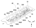
なお、挿入器具本体収容陥没部303及びプランジャー収容陥没部304を形成する陥没形状は、ケース30に収容される眼内レンズ挿入器具10の移動を規制するための移動規制部900となる。移動規制部900はケース本体70の陥没量を変化させることで形成されている。本実施形態のケース30は、移動規制部900を複数備えており、眼内レンズ挿入器具10の異なる部位に各々の移動規制部900(900A〜900G)を当接させている。より詳しくは、本実施形態のケース30は、ケース30に収容された眼内レンズ挿入器具10の押圧部220、軸基部210、及び張り出し部190に移動規制部900(900A〜900G)を当接させている。ケース本体70が備える移動規制部900によって、ケース30に収容された眼内レンズ挿入器具10の上方、左方,右方,前方,後方への移動を規制することが可能とされている。
In addition, the depression shape which forms the insertion instrument main body accommodation depression part 303 and the plunger accommodation depression part 304 becomes the movement control part 900 for regulating the movement of the intraocular lens insertion instrument 10 accommodated in the case 30. The movement restricting portion 900 is formed by changing the amount of depression of the case main body 70. The case 30 of the present embodiment includes a plurality of movement restriction units 900, and the movement restriction units 900 (900A to 900G) are brought into contact with different parts of the intraocular lens insertion device 10. More specifically, in the case 30 of the present embodiment, the movement restricting portion 900 (900A to 900G) is brought into contact with the pressing portion 220, the shaft base portion 210, and the overhang portion 190 of the intraocular lens insertion device 10 accommodated in the case 30. I am letting. The movement restricting portion 900 included in the case main body 70 can restrict the movement of the intraocular lens insertion device 10 accommodated in the case 30 upward, leftward, rightward, forward, and backward.
なお、本実施形態のケース30は、ケース30に収容された眼内レンズ挿入器具10の下方への移動の抑制を、後述する支持部材50の支持部(第一支持部501,第二支持部503)によって行うこととしている。本実施形態のケース本体70は薄肉の樹脂で形成されているため変形が容易とされている。したがって、例えば、移動規制部900が眼内レンズ挿入器具10を挟持する形態とすれば、移動規制部900でもケース30に収容された眼内レンズ挿入器具10の下方への移動を抑制できる。ただし、この場合、ケース30から眼内レンズ挿入器具10を取り出す際に力を要する可能性が高い。ケース本体70はシートを変形させる加工方法で形成するため、成形精度を出し難い。また、ケース本体70は薄肉の樹脂で形成されているため変形しやすい。したがって、ケース30から眼内レンズ挿入器具10を取り出す際の取り出し力を好適にすることは困難と考えられる。一方、本実施形態のケース30は、ケース本体70とは異なる加工方法によって形成した支持部(後述する第一支持部501,第二支持部503)を備えることで、ケース30に収容される眼内レンズ挿入器具10を支持部(第一支持部501,第二支持部503)で好適に支持するとともに、ケース30から好適な力で眼内レンズ挿入器具10を取り出すことを可能としている。
<1−3.支持部材>
In addition, the case 30 of this embodiment suppresses the downward movement of the intraocular lens insertion device 10 accommodated in the case 30 by supporting portions (first support portion 501 and second support portion) of the support member 50 described later. 503). Since the case main body 70 of the present embodiment is formed of a thin resin, it can be easily deformed. Therefore, for example, if the movement restriction unit 900 is configured to sandwich the intraocular lens insertion device 10, the movement restriction unit 900 can also suppress the downward movement of the intraocular lens insertion device 10 accommodated in the case 30. However, in this case, there is a high possibility that a force is required when taking out the intraocular lens insertion device 10 from the case 30. Since the case main body 70 is formed by a processing method for deforming the sheet, it is difficult to obtain molding accuracy. The case body 70 is easily deformed because it is made of a thin resin. Therefore, it is considered difficult to make the removal force suitable for removing the intraocular lens insertion device 10 from the case 30. On the other hand, the case 30 of the present embodiment is provided with support portions (a first support portion 501 and a second support portion 503 described later) formed by a processing method different from that of the case main body 70, so that the eyes accommodated in the case 30 are accommodated. The inner lens insertion device 10 is suitably supported by the support portions (the first support portion 501 and the second support portion 503), and the intraocular lens insertion device 10 can be taken out from the case 30 with a suitable force.
<1-3. Support member>
図4を用いて本実施形態の支持部材50を説明する。なお、真空成形法で成形したケース本体70と異なり、支持部材50は樹脂材料を用いた射出成形(モールド成型)、樹脂の削り出しによる切削加工などで成形されていればよい。なお、支持部材50に金属材料を使用してもよい。支持部材50は第一支持部501と第二支持部503と連結部502とを備える。第一支持部501は支持部材50の先端に位置される。第一支持部501は、挿入器具本体100の可動部材122の可動を規制すると共に、ケース30内で眼内レンズ挿入器具10を支持するための部材とされている。第一支持部501の基端に連結部502が接続される。連結部502は、第一支持部501と第二支持部503を連結する部材であり、連結部502によって支持部材50が一体成形されている。連結部502の基端に第二支持部503が位置される。第一支持部501は第一挟持部510(510A,510B)と可動規制部504とノズル部保護部505とを備える。ノズル部保護部505は第一支持部501の先端に位置される。ノズル部保護部505の基端に可動規制部504が接続される。可動規制部504の基端に第一挟持部510(510A,510B)が接続される。なお、可動規制部504は挿入器具本体100の可動部材122の可動を規制する。したがって、第一支持部501が挿入器具本体100と係合すると、挿入器具本体100の可動部材122の可動が規制される。ノズル部保護部505は先細り部111(図3参照)の側方(本実施形態の図2では先細り部111の下方,右方,及び左方)に位置され、挿入器具本体100の挿入部110の破損を抑制する。なお、第一支持部501を第一挟持部510(510A,510B)と可動規制部504で形成してもよい。なお、第一支持部501はケース本体70と係合するための第一ケース係合部610を複数箇所に備えている。第一挟持部510と可動規制部504とノズル部保護部505の詳細は後述する。
The support member 50 of this embodiment is demonstrated using FIG. Note that, unlike the case main body 70 formed by the vacuum forming method, the support member 50 may be formed by injection molding (molding) using a resin material, cutting by resin cutting, or the like. A metal material may be used for the support member 50. The support member 50 includes a first support part 501, a second support part 503, and a connecting part 502. The first support portion 501 is located at the tip of the support member 50. The first support portion 501 is a member for restricting the movement of the movable member 122 of the insertion instrument main body 100 and for supporting the intraocular lens insertion instrument 10 in the case 30. The connecting portion 502 is connected to the base end of the first support portion 501. The connection part 502 is a member that connects the first support part 501 and the second support part 503, and the support member 50 is integrally formed by the connection part 502. The second support part 503 is located at the base end of the connecting part 502. The first support part 501 includes a first clamping part 510 (510A, 510B), a movable restriction part 504, and a nozzle part protection part 505. The nozzle part protection part 505 is located at the tip of the first support part 501. A movable restricting portion 504 is connected to the base end of the nozzle portion protecting portion 505. The first clamping unit 510 (510A, 510B) is connected to the base end of the movable restricting unit 504. The movable restricting portion 504 restricts the movement of the movable member 122 of the insertion instrument main body 100. Therefore, when the first support portion 501 engages with the insertion instrument body 100, the movement of the movable member 122 of the insertion instrument body 100 is restricted. The nozzle part protection part 505 is located on the side of the taper part 111 (see FIG. 3) (lower side, right side, and left side of the taper part 111 in FIG. 2 of this embodiment), and the insertion part 110 of the insertion instrument body 100. Suppresses damage. In addition, you may form the 1st support part 501 with the 1st clamping part 510 (510A, 510B) and the movable control part 504. FIG. In addition, the 1st support part 501 is equipped with the 1st case engaging part 610 for engaging with the case main body 70 in several places. Details of the first clamping unit 510, the movable regulating unit 504, and the nozzle unit protecting unit 505 will be described later.
連結部502は第一支持部501の基端に接続されている。連結部502は板状の支基とされており、連結部502は、挿入器具本体100の設置部120の基端から張り出し部190の先端までの長さより若干短く形成されている。連結部502の長手方向全長の略半分の位置の左右端には、連結部502を左方向及び左方向から括れさせる幅狭部700が形成されている。幅狭部700によって連結部502には先端から基端までの間に幅狭となる箇所が形成されている。つまり、押出軸Aに交差する左右方向における連結部502の幅は均一ではなく、一部(本実施形態では前後方向の中央部)の幅が他の部分の幅に比べて短い。幅狭部700は、使用者の指と支持部材50との当接を低減させるために設けられている。
The connecting part 502 is connected to the base end of the first support part 501. The connecting portion 502 is a plate-like support base, and the connecting portion 502 is formed slightly shorter than the length from the proximal end of the installation portion 120 of the insertion instrument main body 100 to the distal end of the overhang portion 190. A narrow portion 700 is formed at the left and right ends of the half of the total length in the longitudinal direction of the connecting portion 502 to narrow the connecting portion 502 from the left direction and the left direction. A narrow portion is formed in the connecting portion 502 by the narrow portion 700 from the front end to the base end. That is, the width of the connecting portion 502 in the left-right direction intersecting the extrusion axis A is not uniform, and the width of a part (the central portion in the front-rear direction in this embodiment) is shorter than the width of the other portions. The narrow portion 700 is provided to reduce the contact between the user's finger and the support member 50.
第二支持部503は連結部502の基端に接続されている。第二支持部503は、第二挟持部520(520A,520B)と張出当接部800と第二ケース係合部620(620A,620B)を備える。第二挟持部520は第二支持部503の先端に位置される。第二支持部503の基端に張出当接部800が接続される。張出当接部800の左右両端には第二ケース係合部620が接続される。第二挟持部520は第一挟持部510と略同じ形状で形成されている。張出当接部800は挿入器具本体100の張り出し部190と当接し、張出当接部800は、支持した挿入器具本体100の前方への移動を抑制する(図6参照)。
The second support portion 503 is connected to the base end of the connecting portion 502. The 2nd support part 503 is provided with the 2nd clamping part 520 (520A, 520B), the overhang | projection contact part 800, and the 2nd case engagement part 620 (620A, 620B). The second clamping part 520 is located at the tip of the second support part 503. The overhanging contact portion 800 is connected to the proximal end of the second support portion 503. Second case engagement portions 620 are connected to the left and right ends of the overhang contact portion 800. The second clamping part 520 is formed in substantially the same shape as the first clamping part 510. The overhanging contact portion 800 is in contact with the overhanging portion 190 of the insertion instrument body 100, and the overhanging contact portion 800 suppresses the forward movement of the supported insertion device body 100 (see FIG. 6).
図1,図4,図8を用いて本実施形態の挟持部(第一挟持部510及び第二挟持部520)を説明する。なお、第一挟持部510と第二挟持部520は略同じ形状で形成されているため、以降の説明では第二挟持部520を用いて説明する。第二挟持部520は右側挟持部520Aと左側挟持部520Bを備える。なお、右側挟持部520Aと左側挟持部520Bは軸対象の形状で形成されており、長手方向に伸びる支持部材50の中心線から同じ距離離間した位置に右側挟持部520Aと左側挟持部520Bが形成されている。右側挟持部520Aは、挟持部平板部521Aと挟持部突出部522Aを備える。挟持部平板部521Aは平板状の部材であり、連結部502と接続される第二支持部503の板状支基507の左右端部から下方(図4だと上方)に伸長した突出形状で形成されている。板状支基507から下方へ遠ざかる方向に伸びる挟持部平板部521Aの長さは、ケース本体70に支持部材50を装着した際に、挟持部平板部521Aの先端が基準平面Pを超えない長さで形成されている。本実施形態の挟持部平板部521Aの長さは、挿入器具本体100の本体筒部130の厚さLHB(上下方向)の半分を超えるが、本体筒部130の厚さLHB(上下方向)よりも若干短い長さで形成されている。また、左右一対の挟持部平板部521Aの内面(互いに面する面)の間隔LWCは、本体筒部130の幅(左右方向)の最大値LWBよりも若干長くなるように離間して形成されている。
The clamping part (the first clamping part 510 and the second clamping part 520) of the present embodiment will be described with reference to FIGS. In addition, since the 1st clamping part 510 and the 2nd clamping part 520 are formed in the substantially same shape, it demonstrates using the 2nd clamping part 520 in subsequent description. The second clamping unit 520 includes a right clamping unit 520A and a left clamping unit 520B. The right holding part 520A and the left holding part 520B are formed in the shape of an axial object, and the right holding part 520A and the left holding part 520B are formed at the same distance from the center line of the support member 50 extending in the longitudinal direction. Has been. The right clamping part 520A includes a clamping part flat plate part 521A and a clamping part protruding part 522A. The sandwiching portion flat plate portion 521A is a flat plate-like member and has a protruding shape extending downward (upward in FIG. 4) from the left and right ends of the plate-like support base 507 of the second support portion 503 connected to the connecting portion 502. Is formed. The length of the sandwiching portion flat plate portion 521A extending in a direction away from the plate-like support base 507 is such that the tip of the sandwiching portion flat plate portion 521A does not exceed the reference plane P when the support member 50 is attached to the case body 70. Is formed. The length of the sandwiching portion flat plate portion 521A of the present embodiment exceeds half the thickness LHB (vertical direction) of the main body cylindrical portion 130 of the insertion instrument main body 100, but from the thickness LHB (vertical direction) of the main body cylindrical portion 130. Is also formed with a slightly shorter length. Further, the distance LWC between the inner surfaces (surfaces facing each other) of the pair of left and right sandwiching portion flat plate portions 521A is formed so as to be slightly longer than the maximum value LWB of the width (left and right direction) of the main body cylindrical portion 130. Yes.
挟持部平板部521Aの先端部の内面には、対向する挟持部平板部521Bの方向に突出する挟持部突出部522Aが設けられている。挟持部突出部522Aの押出軸Aと直交する断面の外郭線は、内側(図4だと右方)に向かって突出する円弧形状を描いている。挟持部突出部522Aの上下端部は、挟持部平板部521Aの外郭線と滑らかに接続されている。なお、一対の挟持部突出部522(522A,522B)同士が最も近づく挟持部突出部522の突出頂点を結んだ線長LWAは、本体筒部130の幅(左右方向)の最大値LWBよりも若干短く形成されている。また、挟持部突出部522の突出頂点が形成される板状支基507からの距離LHAは、本体筒部130の厚さLHB(上下方向)の半分を若干超える距離とされている。したがって、眼内レンズ挿入器具10の外側面と第二支持部503の板状支基507とが当接する地点まで眼内レンズ挿入器具10と支持部材50が近接されると、一対の第二挟持部520(520A,520B)によって眼内レンズ挿入器具10の本体筒部130が挟持される。また、挟持部平板部521Aが下方へ向くように支持部材50がケース本体70に装着されていても、ケース30から眼内レンズ挿入器具10が落下し難い形状で第二挟持部520が形成されている。なお、本実施形態の眼内レンズ挿入器具10は、本体筒部130の壁部の外側面に挟持部(第一挟持部510,第二挟持部520)の形状に対応した挟持部陥没部523を設けており、より好適に眼内レンズ挿入器具10を支持できる。挟持部陥没部523はベース支基506又は板状支基507に平行な平行面と、平行面に直交する直交面で形成されている。挟持部陥没部523を設けることで、眼内レンズ挿入器具10の重さが挟持部(510,520)に掛かっても、挟持部(510,520)の挟持部平板部521が外側に開き難い機構になっている。したがって、眼内レンズ挿入器具10の自重によって支持部(501,503)の支持が外れてしまう事象を、より生じ難くしている。
On the inner surface of the distal end portion of the sandwiching portion flat plate portion 521A, a sandwiching portion projecting portion 522A projecting in the direction of the opposing sandwiching portion flat plate portion 521B is provided. The outline of the cross-section perpendicular to the extrusion axis A of the sandwiching projection 522A describes an arc shape that projects inward (to the right in FIG. 4). The upper and lower ends of the sandwiching portion projecting portion 522A are smoothly connected to the outline of the sandwiching portion flat plate portion 521A. Note that the line length LWA connecting the protrusion vertices of the sandwiching portion protrusions 522 that the pair of sandwiching portion protrusions 522 (522A, 522B) are closest to each other is larger than the maximum value LWB of the width (left and right direction) of the main body cylindrical portion 130 It is formed slightly shorter. Further, the distance LHA from the plate-like support base 507 at which the protrusion apex of the sandwiching protrusion 522 is formed is slightly longer than half the thickness LHB (vertical direction) of the main body cylinder part 130. Therefore, when the intraocular lens insertion device 10 and the support member 50 are brought close to a point where the outer surface of the intraocular lens insertion device 10 and the plate-like support base 507 of the second support portion 503 come into contact with each other, the pair of second holding members The main body cylinder part 130 of the intraocular lens insertion device 10 is held between the parts 520 (520A, 520B). Further, even if the support member 50 is mounted on the case main body 70 so that the sandwiching portion flat plate portion 521A faces downward, the second sandwiching portion 520 is formed in such a shape that the intraocular lens insertion device 10 is unlikely to fall from the case 30. ing. In addition, the intraocular lens insertion device 10 of the present embodiment has a sandwiching portion depressed portion 523 corresponding to the shape of the sandwiching portion (the first sandwiching portion 510 and the second sandwiching portion 520) on the outer surface of the wall portion of the main body cylindrical portion 130. The intraocular lens insertion device 10 can be more suitably supported. The sandwiching portion depressed portion 523 is formed by a parallel surface parallel to the base support base 506 or the plate-like support base 507 and an orthogonal surface orthogonal to the parallel surface. By providing the clamping part depression part 523, even if the weight of the intraocular lens insertion device 10 is applied to the clamping part (510, 520), the clamping part flat plate part 521 of the clamping part (510, 520) is difficult to open outward. It is a mechanism. Therefore, the phenomenon that the support portions (501, 503) are unsupported due to the weight of the intraocular lens insertion device 10 is made less likely to occur.
続けて図4,図9を用いて本実施形態の可動規制部504について説明する。可動規制部504は、板状のベース支基506と,ベース支基506の左右各々の端部から下方(図4だと上方)に伸びる左右側板530(530A,530B)を備える。ベース支基506の略中央には、下方に伸びる一対の突出部535が形成されている。突出部535は、眼内レンズ挿入器具10の設置部120の壁部に形成されている開口孔を貫通し、設置部120に充填される眼内レンズ1の移動を抑制する。また、左右側板530の内面(左右側板530同士が対向する面側)には、左右側板530の上端から下方に伸びる複数のリブ(531〜533)が形成されている。なお、本実施形態のリブ(531〜533)の基端はベース支基506に接続されている。リブ(531〜533)は先端方向に離間して配置されている。離間した各々のリブ(531〜533)の間隔は、挿入器具本体100の設置部120の左方及び右方の外側面に形成されている凹凸形状に対応した間隔で形成されている。複数のリブ(531〜533)は、基端側に配置されるリブ(531〜533)ほど、リブ(531〜533)の長さが長くなるように形成されている。
Next, the movable restricting portion 504 of this embodiment will be described with reference to FIGS. The movable restricting portion 504 includes a plate-like base support base 506 and left and right side plates 530 (530A, 530B) extending downward (upward in FIG. 4) from the left and right ends of the base support base 506. A pair of projecting portions 535 extending downward is formed in the approximate center of the base support base 506. The protruding portion 535 passes through an opening formed in the wall portion of the installation portion 120 of the intraocular lens insertion instrument 10 and suppresses the movement of the intraocular lens 1 filled in the installation portion 120. A plurality of ribs (531 to 533) extending downward from the upper ends of the left and right side plates 530 are formed on the inner surface of the left and right side plates 530 (the surface side where the left and right side plates 530 face each other). In addition, the base end of the rib (531-533) of this embodiment is connected to the base support base 506. The ribs (531 to 533) are spaced apart in the distal direction. The spaced apart ribs (531 to 533) are formed at intervals corresponding to the concave and convex shapes formed on the left and right outer surfaces of the installation portion 120 of the insertion instrument main body 100. The plurality of ribs (531 to 533) are formed such that the ribs (531 to 533) are longer as the ribs (531 to 533) are arranged closer to the base end side.
なお、リブ(531〜533)の長さとは、ベース支基506からリブの先端(図4だと上端)までを示す。例えば、本実施形態のリブ531の長さは、リブ533の長さよりも長く形成されている。リブ(531〜533)の先端が可動部材122に当接することによって、ケース30に収容された眼内レンズ挿入器具10の可動部材122の可動が規制される(図9(a)参照)。ケース30から眼内レンズ挿入器具10を取り出した際には、眼内レンズ挿入器具10の可動部材122の可動の規制が解除され、可動部材122を押出軸Aの方向に押し込むことが可能となる(図9(b)参照)。なお、図9(b)は図9(a)との比較のために眼内レンズ挿入器具10を下方に取り出す例示であり、ケース30を上下方向逆にして、眼内レンズ挿入器具10を上方に取り出してもよい。なお、ケース30を他の方向に向けて眼内レンズ挿入器具10をケース30の向きに対応した方向に取り出してもよいことは言うまでもない。
The length of the ribs (531 to 533) indicates from the base support base 506 to the tip of the rib (the upper end in FIG. 4). For example, the length of the rib 531 of this embodiment is longer than the length of the rib 533. The movement of the movable member 122 of the intraocular lens insertion device 10 accommodated in the case 30 is regulated by the tips of the ribs (531 to 533) coming into contact with the movable member 122 (see FIG. 9A). When the intraocular lens insertion device 10 is taken out from the case 30, the movable restriction of the movable member 122 of the intraocular lens insertion device 10 is released, and the movable member 122 can be pushed in the direction of the extrusion axis A. (See FIG. 9B). 9B is an example in which the intraocular lens insertion device 10 is taken out downward for comparison with FIG. 9A. The case 30 is turned upside down and the intraocular lens insertion device 10 is moved upward. You may take it out. It goes without saying that the intraocular lens insertion device 10 may be taken out in a direction corresponding to the direction of the case 30 with the case 30 facing in another direction.
なお、前述のとおり、リブ(531〜533)は、設置部120の左方及び右方の外側面に形成されている凹凸形状に対応した間隔で形成されている。詳細には、リブ(531〜533)と設置部120とが僅かに当接される程度の間隔でリブ(531〜533)が形成されている。リブ(531〜533)と設置部120とを軽く係合させている理由は、眼内レンズ挿入システム40の組み立て易さ、及びケース30から眼内レンズ挿入器具10の取り出し易さを向上させるためである。したがって、本実施形態の第一支持部501は、可動規制部504で可動部材122の可動の規制を行い、可動規制部504に連結している第一挟持部510で眼内レンズ挿入器具10の支持を行うこととしている。したがって、本実施形態のケース30は、第一支持部501の装着されたケース30に眼内レンズ挿入器具10を容易に着脱することが可能であり、かつ、可動規制部504で眼内レンズ挿入器具10の可動部材122の可動の規制を好適に行うことが可能とされている。なお、可動規制部504に第一挟持部510を備えてもよい。つまり、支持部材50はケース本体70に着脱可能であるが、使用時に、支持部材50はケース本体70から取り外す必要がないため、支持部材50とケース本体70の係合は、支持部材50と眼内レンズ挿入器具10の係合よりも強い係合力で係合されている。また、本実施形態の眼内レンズ挿入システム40は、支持部材50をケース本体70とは異なる加工方法で形成しているため、例えば、上述したように、眼内レンズ挿入器具10と支持部材50とが係合する構造を形成し易く、支持部材50で眼内レンズ挿入器具10を好適に支持することができる。なお、支持部材50の眼内レンズ挿入器具10と当接する部位を細かい凹凸形状で形成し、摩擦を増加させてもよい。
In addition, as above-mentioned, the rib (531-533) is formed in the space | interval corresponding to the uneven | corrugated shape currently formed in the left side of the installation part 120, and the right outer surface. Specifically, the ribs (531 to 533) are formed at intervals such that the ribs (531 to 533) and the installation portion 120 are slightly in contact with each other. The reason why the ribs (531 to 533) and the installation portion 120 are lightly engaged is to improve the ease of assembling the intraocular lens insertion system 40 and the ease of taking out the intraocular lens insertion device 10 from the case 30. It is. Accordingly, the first support portion 501 of the present embodiment restricts the movable member 122 by the movable restricting portion 504 and the first holding portion 510 connected to the movable restricting portion 504 of the intraocular lens insertion device 10. Support is going to be done. Therefore, in the case 30 of this embodiment, the intraocular lens insertion device 10 can be easily attached to and detached from the case 30 to which the first support portion 501 is attached, and the intraocular lens is inserted by the movable restricting portion 504. It is possible to suitably restrict the movement of the movable member 122 of the instrument 10. Note that the movable restricting portion 504 may be provided with the first clamping portion 510. That is, the support member 50 can be attached to and detached from the case main body 70. However, since the support member 50 does not need to be detached from the case main body 70 during use, The inner lens insertion device 10 is engaged with an engagement force stronger than that of the inner lens insertion device 10. In addition, since the support member 50 is formed by a processing method different from that of the case body 70 in the intraocular lens insertion system 40 of the present embodiment, for example, as described above, the intraocular lens insertion device 10 and the support member 50 are used. Can be easily formed, and the support member 50 can favorably support the intraocular lens insertion device 10. Note that the portion of the support member 50 that comes into contact with the intraocular lens insertion instrument 10 may be formed in a fine uneven shape to increase friction.
続けて、本実施形態のノズル部保護部505について説明する。可動規制部504の先端にノズル部保護部505が接続されている。ノズル部保護部505は、眼内レンズ挿入器具10の挿入部110の損傷を防ぐためのものとされている。つまり、ノズル部保護部505は、眼内レンズ挿入器具10をケース30から取り出す際に、ノズル部112をはじめとする挿入部110の先端部とケース本体70とが当接し、挿入部110を破損してしまう不具合を抑制するものである。特に、ノズル部112の先端はベベル部113によって尖った形状とされているため、不用意に他の部材が当接すると損傷し易い。したがって、本実施形態のノズル部保護部505は、眼内レンズ挿入器具10が傾斜した際に、ノズル部112がケース本体70に当接する前に、ノズル部保護部505と先細り部111とが当接するように形成している。
Next, the nozzle protection unit 505 of this embodiment will be described. A nozzle protection unit 505 is connected to the tip of the movable restriction unit 504. The nozzle part protection part 505 is intended to prevent damage to the insertion part 110 of the intraocular lens insertion device 10. In other words, when removing the intraocular lens insertion device 10 from the case 30, the nozzle part protection part 505 contacts the tip part of the insertion part 110 including the nozzle part 112 and the case body 70, and damages the insertion part 110. It is intended to suppress problems that occur. In particular, since the tip of the nozzle portion 112 is sharpened by the bevel portion 113, it is easily damaged when another member is inadvertently brought into contact therewith. Therefore, when the intraocular lens insertion device 10 is tilted, the nozzle part protection part 505 of the present embodiment has a contact with the nozzle part protection part 505 and the tapered part 111 before the nozzle part 112 contacts the case body 70. It is formed to touch.
なお、第一支持部501の左右側板530の外面側には第一ケース係合部610が形成されている。第一ケース係合部610は左右側板530の外側面から外側に突出し、斜面が上方(図4では下方)に向くテーパー形状で形成されている。また、第二支持部503の張出当接部800の左右両端には第二ケース係合部620が接続されている。第二ケース係合部620は張出当接部800の左右端部から外側に突出し、斜面が上方(図4では下方)に向くテーパー形状で形成されている。第一ケース係合部610及び第二ケース係合部620の各々は、ケース本体70に形成されている複数の支持部材係合部910の少なくともいずれかと係合する。第一ケース係合部610(第二ケース係合部620)と支持部材係合部910とが係合することで、ケース本体70に支持部材50が装着される。
A first case engagement portion 610 is formed on the outer surface side of the left and right side plates 530 of the first support portion 501. The first case engaging portion 610 protrudes outward from the outer surface of the left and right side plates 530 and has a tapered shape with the inclined surface facing upward (downward in FIG. 4). In addition, second case engagement portions 620 are connected to the left and right ends of the overhang contact portion 800 of the second support portion 503. The second case engaging portion 620 protrudes outward from the left and right end portions of the overhanging contact portion 800, and is formed in a tapered shape with the inclined surface facing upward (downward in FIG. 4). Each of the first case engaging portion 610 and the second case engaging portion 620 engages with at least one of the plurality of support member engaging portions 910 formed on the case main body 70. The support member 50 is attached to the case main body 70 by the first case engagement portion 610 (second case engagement portion 620) and the support member engagement portion 910 engaging with each other.
なお、支持部材係合部910は、ケース本体70の凹凸部60の側壁の一部を水平方向かつ陥没空間が少なくなる方向に突出させることで支持部材係合部910が形成されている。ケース本体70の裏面側(図3だと上方)から支持部材50をケース本体70に近接させると、テーパー形状の基端部(図4だと上端部)に形成されている水平面と支持部材係合部910の突出部とが係合し、ケース本体70に支持部材50が装着される。なお、ケース本体70と支持部材50とは押出軸A方向の異なる複数の位置で係合する。本実施形態のケース30は、支持部材50が眼内レンズ挿入器具10を支持した状態でケース30の裏面を下方に向けても、ケース30から支持部材50が外れない係合力でケース本体70と支持部材50とが係合されている。また、本実施形態の支持部材50は、眼内レンズ挿入器具10をケース30から取り出しても、眼内レンズ挿入器具10と一緒に支持部材50が外れてしまうことのない係合力で支持部材50とケース本体70とが係合されている。したがって、ケース本体70とは異なる加工方法で形成した支持部材50で眼内レンズ挿入器具10を好適に支持し、かつ、ケース30から眼内レンズ挿入器具10を容易に取り出すことができる。なお、支持部材50とケース本体70を異なる加工方法で形成するため、支持部材50で眼内レンズ挿入器具10の可動部材122の可動を好適に規制できる。なお、ケース本体70に支持部材50を接着剤で接着してもよいが、使用する接着剤の生体適合性を考慮する必要がある。なお、本実施形態のケース30は、ケース本体70と支持部材50の係合構造と、支持部材50と眼内レンズ挿入器具10の係合構造を異ならせ、支持部材50のケース本体70への好適な装着と、支持部材50による眼内レンズ挿入器具10の好適な支持及び眼内レンズ挿入器具10の好適な取り出しを両立させている。
In addition, the support member engaging part 910 is formed by projecting a part of the side wall of the concavo-convex part 60 of the case main body 70 in the horizontal direction and in a direction in which the depressed space is reduced. When the support member 50 is brought close to the case body 70 from the back side of the case body 70 (upward in FIG. 3), the horizontal surface formed on the tapered base end (upper end in FIG. 4) and the support member The protrusion of the joint portion 910 is engaged, and the support member 50 is attached to the case main body 70. The case main body 70 and the support member 50 are engaged at a plurality of different positions in the direction of the extrusion axis A. The case 30 of the present embodiment has an engagement force that prevents the support member 50 from being detached from the case 30 even when the back surface of the case 30 faces downward while the support member 50 supports the intraocular lens insertion device 10. The support member 50 is engaged. Further, the support member 50 according to the present embodiment has an engagement force that does not cause the support member 50 to come off together with the intraocular lens insertion device 10 even when the intraocular lens insertion device 10 is removed from the case 30. And the case body 70 are engaged. Therefore, the intraocular lens insertion device 10 can be suitably supported by the support member 50 formed by a processing method different from that of the case body 70, and the intraocular lens insertion device 10 can be easily taken out from the case 30. In addition, since the support member 50 and the case main body 70 are formed by different processing methods, the support member 50 can suitably regulate the movement of the movable member 122 of the intraocular lens insertion device 10. Although the support member 50 may be bonded to the case body 70 with an adhesive, it is necessary to consider the biocompatibility of the adhesive used. In addition, the case 30 of this embodiment differs in the engagement structure of the case main body 70 and the support member 50, and the engagement structure of the support member 50 and the intraocular lens insertion instrument 10, and the support member 50 to the case main body 70 is different. A suitable mounting and a suitable support of the intraocular lens insertion device 10 by the support member 50 and a suitable removal of the intraocular lens insertion device 10 are made compatible.
なお、本実施形態のケース30は、ケース30に収容された眼内レンズ挿入器具10の長手方向全長LBの中間となる中間位置(図5だと断面I−Iの位置)に第二支持部503を配置している(図5参照)。したがって、眼内レンズ挿入器具10の長手方向の先端付近又は基端付近の位置だけで眼内レンズ挿入器具10を支持する場合に対して、眼内レンズ挿入器具10の端部と支持箇所との最大距離が短くなるため、ケース30に収容された眼内レンズ挿入器具10の移動を効率よく抑制することができる。また、本実施形態のケース30は、把持空間形成部301よりも先端側と基端側の各々の位置で眼内レンズ挿入器具10を支持する。したがって、眼内レンズ挿入器具10を指で把持した位置の先端側と基端側に各々支持力がかかった状態で眼内レンズ挿入器具10を取り出すため、ケース30の基準平面Pに対して平行な角度で眼内レンズ挿入器具10をケース30から取り出し易くなる(図7参照)。例えば、指で把持した位置の片方(先端側又は基端側の何れか)のみ支持力がかかった状態で眼内レンズ挿入器具10をケース30から取り出す場合、眼内レンズ挿入器具10の先端側又は基端側が基準平面Pに対して傾斜し易くなる。眼内レンズ挿入器具10がケース30の近くで傾斜すると、眼内レンズ挿入器具10の先端部又は基端部がケース本体70とが不用意に当接し、眼内レンズ挿入器具10を破損する可能性がある。なお、長手方向全長LBの中間となる中間位置に第二支持部503を設けず、眼内レンズ挿入器具10の重心位置に設けてもよい。また、長手方向全長LBの中間となる中間位置と重心位置の間に第二支持部503を設けてもよい。
In addition, the case 30 of the present embodiment has the second support portion at an intermediate position (position of the cross section II in FIG. 5) that is the middle of the overall length LB in the longitudinal direction of the intraocular lens insertion device 10 accommodated in the case 30. 503 is arranged (see FIG. 5). Therefore, in contrast to the case where the intraocular lens insertion device 10 is supported only at the position in the vicinity of the distal end or the proximal end in the longitudinal direction of the intraocular lens insertion device 10, Since the maximum distance is shortened, the movement of the intraocular lens insertion device 10 accommodated in the case 30 can be efficiently suppressed. In addition, the case 30 of the present embodiment supports the intraocular lens insertion device 10 at each position on the distal end side and the proximal end side with respect to the grasping space forming portion 301. Therefore, the intraocular lens insertion device 10 is taken out in a state in which the supporting force is applied to the distal end side and the proximal end side of the position where the intraocular lens insertion device 10 is gripped with a finger, and thus parallel to the reference plane P of the case 30. It becomes easy to take out the intraocular lens insertion device 10 from the case 30 at a proper angle (see FIG. 7). For example, when the intraocular lens insertion device 10 is removed from the case 30 in a state where only one of the positions gripped by the finger (either the distal end side or the proximal end side) is supported, the distal end side of the intraocular lens insertion device 10 is removed. Alternatively, the base end side is easily inclined with respect to the reference plane P. When the intraocular lens insertion device 10 is tilted near the case 30, the distal end portion or the base end portion of the intraocular lens insertion device 10 may inadvertently come into contact with the case body 70, and the intraocular lens insertion device 10 may be damaged. There is sex. Note that the second support portion 503 may not be provided at an intermediate position that is the middle of the overall length LB in the longitudinal direction, but may be provided at the center of gravity of the intraocular lens insertion device 10. Moreover, you may provide the 2nd support part 503 between the intermediate position which becomes the middle of longitudinal direction full length LB, and a gravity center position.
なお、本実施形態のケース30は、支持部(501,503)と移動規制部900(900A〜900G)とで眼内レンズ挿入器具10の移動の規制を使い分け、支持部(501,503)と移動規制部900を併用している。より詳しくは、眼内レンズ挿入器具10の移動に対して精度の高い移動規制を要する箇所は支持部(501,503)で眼内レンズ挿入器具10を挟持及び当接させ、大まかな移動の規制を行う箇所は移動規制部900を眼内レンズ挿入器具10に当接させる。したがって、ケース30の全体を射出成形で形成しなくとも、ケース30内で眼内レンズ挿入器具10の移動を好適に規制することができる。したがって、眼内レンズ挿入器具10をケース30に収容した状態で眼内レンズ挿入システム40を移動させても、移動中の振動などによって眼内レンズ挿入器具10が破損または故障する事象を抑制することができる。本実施形態の眼内レンズ挿入システム40は、ケース30の成形にかかる金型費用を低減させることでケース30を安価に製造することができ、眼内レンズ挿入システム40を安価に使用者へ提供できる。
<1−5.組立方法>
作業者は、ケース本体70の表面(図1だと平面)が下方を向くように、ケース本体70を作業台に載せる。続けて作業者は、ケース本体70に支持部材50を装着する。続けて作業者は、支持部材50の装着されたケース30に眼内レンズ挿入器具10を収容する。また、眼内レンズ挿入器具10に眼内レンズ1を充填する。続けて、作業者は、ケース本体70の鍔部300にシート80を接着(溶着)し、眼内レンズ挿入器具10の収容された凹凸部60の収容空間をシート80で密閉する。続けて、シート80で密閉されたケース30をガスで滅菌する。なお、シート80は滅菌ガスを通過させるため、ケース30にシート80が貼り付けられた状態でケース30を滅菌できる。続けて、作業者は、ケース30の上方外側面にシール82を貼り付ける。続けて作業者は、紙箱81に滅菌処理のされた眼内レンズ挿入システム40を収容する。なお、紙箱81は厚紙で形成されている。紙箱81の主な目的は、ケース30に収容されている眼内レンズ挿入器具10の種類の識別性を向上させることと、複数の眼内レンズ挿入システム40を重ねて搬送及び保管し易くなる点がある。なお、紙箱81を使用せずに眼内レンズ挿入システム40を搬送してもよい。
<2.使用方法>
In addition, the case 30 of this embodiment uses the restriction | limiting of the movement of the intraocular lens insertion device 10 separately by the support part (501,503) and the movement control part 900 (900A-900G), and uses the support part (501,503). The movement restricting unit 900 is used together. More specifically, at locations where movement control with high accuracy is required for movement of the intraocular lens insertion instrument 10, the intraocular lens insertion instrument 10 is clamped and brought into contact with the support portions (501, 503) to roughly control the movement. The movement restricting portion 900 is brought into contact with the intraocular lens insertion device 10 at a location where the movement is performed. Therefore, even if the entire case 30 is not formed by injection molding, the movement of the intraocular lens insertion device 10 can be suitably restricted within the case 30. Therefore, even if the intraocular lens insertion system 40 is moved in a state where the intraocular lens insertion device 10 is housed in the case 30, an event in which the intraocular lens insertion device 10 is damaged or broken due to vibration during movement or the like is suppressed. Can do. The intraocular lens insertion system 40 of the present embodiment can manufacture the case 30 at low cost by reducing the mold cost for molding the case 30, and provides the intraocular lens insertion system 40 to the user at low cost. it can.
<1-5. Assembly method>
The operator places the case body 70 on the work table so that the surface of the case body 70 (a plane in FIG. 1) faces downward. Subsequently, the worker attaches the support member 50 to the case body 70. Subsequently, the worker houses the intraocular lens insertion device 10 in the case 30 to which the support member 50 is attached. In addition, the intraocular lens 1 is filled in the intraocular lens insertion device 10. Subsequently, the operator adheres (welds) the sheet 80 to the collar portion 300 of the case main body 70, and seals the accommodation space of the uneven portion 60 in which the intraocular lens insertion device 10 is accommodated with the sheet 80. Subsequently, the case 30 sealed with the sheet 80 is sterilized with gas. Since the sheet 80 allows sterilization gas to pass, the case 30 can be sterilized with the sheet 80 attached to the case 30. Subsequently, the operator attaches the seal 82 to the upper outer surface of the case 30. Subsequently, the operator houses the sterilized intraocular lens insertion system 40 in the paper box 81. The paper box 81 is formed of thick paper. The main purpose of the paper box 81 is to improve the identification of the type of the intraocular lens insertion device 10 accommodated in the case 30, and to make it easier to transport and store a plurality of intraocular lens insertion systems 40. There is. The intraocular lens insertion system 40 may be transported without using the paper box 81.
<2. Usage>
使用者は、紙箱81から眼内レンズ挿入システム40を引き出す(図11参照)。続けて、ケース30に貼り付けられているシート80を剥がす(図10参照)。続けて使用者は、ケース30から眼内レンズ挿入器具10を取り出す(図7参照)。なお、ケース30の把持空間形成部301に指を入れて、眼内レンズ挿入器具10の本体筒部130を側方(左右方向)から把持して取り出す。このとき、ケース30から眼内レンズ挿入器具10を取り出す際は、使用者の反対の手又は介助者の手で、ケース本体70の表面(図1の平面側)の凹凸部60を側方から把持する。なお、ケース30から眼内レンズ挿入器具10を取り出す際に、ケース30を作業台などに載置して眼内レンズ挿入器具10を取り出してもよい。なお、ケース30から眼内レンズ挿入器具10を取り出すと、可動部材122の可動の規制が解除される。続けて使用者は、眼内レンズ挿入器具10の注入口に粘弾性物質を注入した後、可動部材122を押し込む(押出軸Aの方向に押す)。可動部材122が押し込まれることで眼内レンズ1は押出軸A上に移動する。続けて使用者は、眼内レンズ挿入器具10のノズル部112を患者眼の切開創に差し込み、プランジャー200を押出軸Aの先端方向に押し込むことで眼内レンズ1を患者眼の眼内に挿入する。
<3.作用及び効果>
The user pulls out the intraocular lens insertion system 40 from the paper box 81 (see FIG. 11). Subsequently, the sheet 80 attached to the case 30 is peeled off (see FIG. 10). Subsequently, the user takes out the intraocular lens insertion device 10 from the case 30 (see FIG. 7). In addition, a finger is put into the grip space forming part 301 of the case 30 and the main body cylinder part 130 of the intraocular lens insertion device 10 is gripped and taken out from the side (left and right direction). At this time, when removing the intraocular lens insertion device 10 from the case 30, the concave / convex portion 60 on the surface of the case main body 70 (on the flat side in FIG. 1) is viewed from the side with the hand opposite to the user or the hand of the assistant. Hold it. When removing the intraocular lens insertion device 10 from the case 30, the intraocular lens insertion device 10 may be taken out by placing the case 30 on a work table or the like. When the intraocular lens insertion device 10 is taken out from the case 30, the movable restriction of the movable member 122 is released. Subsequently, the user injects the viscoelastic material into the injection port of the intraocular lens insertion device 10 and then presses the movable member 122 (presses in the direction of the extrusion axis A). When the movable member 122 is pushed, the intraocular lens 1 moves on the extrusion axis A. Subsequently, the user inserts the nozzle part 112 of the intraocular lens insertion device 10 into the incision of the patient's eye and pushes the plunger 200 in the direction of the distal end of the push-out axis A so that the intraocular lens 1 enters the eye of the patient's eye. insert.
<3. Action and Effect>
本実施形態の眼内レンズ挿入器具10を収容するケース30は、眼内レンズ挿入器具10全体を収容する凹凸部60がシートを変形させる加工方法によって形成されているケース本体70と,凹凸部60に収容される眼内レンズ挿入器具10をケース本体70とは異なる加工方法によって形成されて、ケース30に装着される支持部(501,503)で眼内レンズ挿入器具10を支持する。ケース本体70とは異なる加工方法によって形成された支持部(501,503)で眼内レンズ挿入器具10を支持するため、ケース30内部における眼内レンズ挿入器具10の移動を好適に抑制できる。また、好適な支持力で眼内レンズ挿入器具10を支持するため、使用時に、ケース30から眼内レンズ挿入器具10を容易に取り出すことができる。眼内レンズ挿入器具10全体を収容するケース本体70の投影面積よりも支持部(501,503)の投影面積は小さいため、支持部(501,503)を安価に製造することができる。また、支持部(501,503)はプランジャー200を収容またはプランジャー200に当接させず支持するため、支持部(501,503)を安価に製造することができる。また、本実施形態の眼内レンズ挿入器具10用のケース30は、ケース30から眼内レンズ挿入器具10を取り出しても、ケース30に支持部(501,503)が残る。換言するなら、支持部(501,503)は、眼内レンズ挿入器具10との係合力よりも大きい係合力でケース本体70に係合されている。したがって、ケース本体70とは異なる加工手法で形成した支持部(501,503)で、ケース本体70に収容する眼内レンズ挿入器具10を好適に支持し、かつ、ケース本体70に支持部(501,503)を残したまま、ケース30から眼内レンズ挿入器具10を好適に取り出すことができる。支持部(501,503)との係合が外れた状態で眼内レンズ挿入器具10はケース30から取り出されるため、取り出した眼内レンズ挿入器具10を速やかに使用することができる。
The case 30 that accommodates the intraocular lens insertion device 10 of the present embodiment includes a case main body 70 in which the uneven portion 60 that accommodates the entire intraocular lens insertion device 10 is formed by a processing method that deforms the sheet, and the uneven portion 60. The intraocular lens insertion device 10 accommodated in the case 30 is formed by a processing method different from that of the case main body 70, and the intraocular lens insertion device 10 is supported by support portions (501 and 503) attached to the case 30. Since the intraocular lens insertion device 10 is supported by the support portions (501, 503) formed by a processing method different from the case main body 70, the movement of the intraocular lens insertion device 10 inside the case 30 can be suitably suppressed. Moreover, since the intraocular lens insertion device 10 is supported with a suitable supporting force, the intraocular lens insertion device 10 can be easily taken out from the case 30 during use. Since the projection area of the support portions (501, 503) is smaller than the projection area of the case body 70 that accommodates the entire intraocular lens insertion instrument 10, the support portions (501, 503) can be manufactured at low cost. Further, since the support portions (501, 503) accommodate the plunger 200 without supporting or contacting the plunger 200, the support portions (501, 503) can be manufactured at low cost. Further, in the case 30 for the intraocular lens insertion device 10 of the present embodiment, even if the intraocular lens insertion device 10 is taken out from the case 30, the support portions (501, 503) remain in the case 30. In other words, the support portions (501 and 503) are engaged with the case main body 70 with an engagement force larger than the engagement force with the intraocular lens insertion instrument 10. Therefore, the intraocular lens insertion device 10 housed in the case main body 70 is suitably supported by the support portions (501, 503) formed by a processing method different from that of the case main body 70, and the support portion (501) is supported on the case main body 70. , 503), the intraocular lens insertion device 10 can be suitably removed from the case 30. Since the intraocular lens insertion device 10 is removed from the case 30 in a state where the engagement with the support portions (501, 503) is released, the removed intraocular lens insertion device 10 can be used quickly.
また、本実施形態の眼内レンズ挿入器具10を収容するケース30は、支持部(501,503)を複数備え、眼内レンズ挿入器具10の異なる部位に複数の支持部(501,503)の各々を当接させて眼内レンズ挿入器具10を支持する。眼内レンズ挿入器具10の異なる部位を複数の支持部(501,503)で支持するため、より好適に眼内レンズ挿入器具10をケース30内で支持することができる。
In addition, the case 30 that accommodates the intraocular lens insertion device 10 of the present embodiment includes a plurality of support portions (501, 503), and a plurality of support portions (501, 503) are provided at different parts of the intraocular lens insertion device 10. The intraocular lens insertion device 10 is supported by bringing them into contact with each other. Since different portions of the intraocular lens insertion device 10 are supported by the plurality of support portions (501, 503), the intraocular lens insertion device 10 can be more preferably supported in the case 30.
また、本実施形態の眼内レンズ挿入器具10を収容するケース30は、複数の支持部(501,503)の少なくとも2つを連結する連結部502を備える。連結部502を備えることで、支持部(501,503)のケース本体70への装着作業が容易になる。また、例えば、複数の支持部(501,503)を好適な位置関係で設けることができる。また、本実施形態では、連結部502と、連結部502によって連結される複数の支持部(501,503)とが一体形成されている。例えば、複数の支持部(501,503)を一体成形することで、ケース30を安価に提供することができる。
In addition, the case 30 that houses the intraocular lens insertion device 10 of the present embodiment includes a connecting portion 502 that connects at least two of the plurality of support portions (501, 503). By providing the connection part 502, the mounting | wearing operation | work to the case main body 70 of a support part (501,503) becomes easy. Further, for example, a plurality of support portions (501, 503) can be provided in a suitable positional relationship. Moreover, in this embodiment, the connection part 502 and the some support part (501,503) connected by the connection part 502 are integrally formed. For example, the case 30 can be provided at low cost by integrally forming the plurality of support portions (501, 503).
また、本実施形態の眼内レンズ挿入器具10を収容するケース30は、眼内レンズ挿入器具10がケース30に収容された状態において、眼内レンズ挿入器具10とケース本体70との間に連結部502を挟み込む。眼内レンズ挿入器具10とケース本体70の間に連結部502を挟み込むことで、例えば、眼内レンズ挿入器具10をケース30から取り出す際に、使用者の指が連結部502に妨げられることなく眼内レンズ挿入器具10を容易に把持することができる。したがって、ケース30から眼内レンズ挿入器具10を容易に取り出すことができる。
In addition, the case 30 that houses the intraocular lens insertion device 10 of the present embodiment is connected between the intraocular lens insertion device 10 and the case body 70 in a state where the intraocular lens insertion device 10 is housed in the case 30. The part 502 is inserted. By inserting the connecting portion 502 between the intraocular lens insertion device 10 and the case main body 70, for example, when removing the intraocular lens insertion device 10 from the case 30, the user's finger is not obstructed by the connecting portion 502. The intraocular lens insertion device 10 can be easily grasped. Therefore, the intraocular lens insertion device 10 can be easily taken out from the case 30.
また、本実施形態の連結部502は、挿入器具本体100の幅よりも狭い幅となる幅狭部700を備えている。眼内レンズ挿入器具10を支持部材50で支持した際に、眼内レンズ挿入器具10の長手方向に直交する方向の連結部502の幅を狭めている。幅狭部700で狭めた幅は、筒状の眼内レンズ挿入器具10の太さよりも狭めるように形成している。幅狭部700によって、使用者が眼内レンズ挿入器具10を指で把持する際に、眼内レンズ挿入器具10と共に連結部502を把持してしまう不具合を抑制することができる。したがって、ケース30から眼内レンズ挿入器具10を好適に取り出すことができる。
Further, the connecting portion 502 of the present embodiment includes a narrow portion 700 that is narrower than the width of the insertion instrument main body 100. When the intraocular lens insertion device 10 is supported by the support member 50, the width of the connecting portion 502 in the direction orthogonal to the longitudinal direction of the intraocular lens insertion device 10 is reduced. The width narrowed by the narrow portion 700 is formed to be narrower than the thickness of the tubular intraocular lens insertion instrument 10. The narrow portion 700 can suppress a problem that the user grips the connecting portion 502 together with the intraocular lens insertion device 10 when the user grips the intraocular lens insertion device 10 with a finger. Therefore, the intraocular lens insertion device 10 can be suitably taken out from the case 30.
また、本実施形態のケース本体70は、凹凸部60の凹凸形状によって形成されて、ケース30に収容される挿入器具本体100を把持する指が挿入されるための空間を形成する把持空間形成部301を備える。支持部(501,503)は把持空間形成部301を跨いだ複数の位置で挿入器具本体100を支持する。把持空間形成部301を跨いだ複数の位置で挿入器具本体100を支持することで、眼内レンズ挿入器具10を好適に支持でき、また、眼内レンズ挿入器具10をケース30から好適に取り出すことができる。
In addition, the case main body 70 of the present embodiment is formed by the concavo-convex shape of the concavo-convex portion 60, and a grasping space forming portion that forms a space for inserting a finger that grasps the insertion instrument main body 100 accommodated in the case 30. 301 is provided. The support portions (501, 503) support the insertion instrument main body 100 at a plurality of positions across the grip space forming portion 301. By supporting the insertion instrument body 100 at a plurality of positions across the gripping space forming portion 301, the intraocular lens insertion instrument 10 can be favorably supported, and the intraocular lens insertion instrument 10 can be suitably removed from the case 30. Can do.
例えば、把持空間形成部301の片側だけで眼内レンズ挿入器具10を支持する場合、眼内レンズ挿入器具10をケース30から取り出す際に、支持部(501,503)を支点として眼内レンズ挿入器具10が傾き、ノズル部112を損傷してしまう恐れがある。本実施形態のケース30は、取り出す際の眼内レンズ挿入器具10の傾斜を抑制することができる。なお、換言するなら、本実施形態の眼内レンズ挿入器具収容用のケース30は、ケース本体70は、凹凸部60の凹凸形状によって形成され、ケース30に収容される挿入器具本体100を把持する指が挿入されるための空間を形成する把持空間形成部301と、凹凸部60に収容される眼内レンズ挿入器具10の軸方向において、把持空間形成部301よりも先端側と後端側の各々に形成され、支持部(501,503)が装着される装着部として支持部材係合部910を備えている。
For example, when the intraocular lens insertion device 10 is supported only on one side of the grasping space forming unit 301, when the intraocular lens insertion device 10 is removed from the case 30, the intraocular lens is inserted using the support portions (501, 503) as fulcrums. The instrument 10 may tilt and damage the nozzle part 112. The case 30 of the present embodiment can suppress the inclination of the intraocular lens insertion device 10 when taking out. In other words, in the case 30 for accommodating an intraocular lens insertion instrument of the present embodiment, the case body 70 is formed by the concavo-convex shape of the concavo-convex part 60 and holds the insertion instrument main body 100 accommodated in the case 30. In the axial direction of the grasping space forming portion 301 that forms a space for inserting a finger and the intraocular lens insertion device 10 accommodated in the concavo-convex portion 60, the front end side and the rear end side of the grasping space forming portion 301 are disposed. A support member engaging portion 910 is provided as a mounting portion that is formed on each of which the support portions (501, 503) are mounted.
また、本実施形態の眼内レンズ挿入器具10を収容するケース30は、支持部(501,503)の少なくともいずれかを、ケース30に収容される眼内レンズ挿入器具10の長手方向全長の中間位置に配置する。支持部(501,503)を眼内レンズ挿入器具10の長手方向全長LBの中間位置に配置することで、例えば、眼内レンズ挿入器具10の下方からの支持が少なくても、ケース30内で眼内レンズ挿入器具10の上下方向の移動を好適に抑制することができる。
In addition, the case 30 that accommodates the intraocular lens insertion device 10 of the present embodiment has at least one of the support portions (501, 503) in the middle of the full length in the longitudinal direction of the intraocular lens insertion device 10 that is accommodated in the case 30. Place in position. By disposing the support portions (501, 503) at an intermediate position of the full length LB in the longitudinal direction of the intraocular lens insertion device 10, for example, even if there is little support from below the intraocular lens insertion device 10, the case 30 The movement of the intraocular lens insertion device 10 in the vertical direction can be suitably suppressed.
また、本実施形態では、支持部の少なくともいずれかは、ケース30に収容される設置部120に接触することで眼内レンズ挿入器具10を支持する。ケース30内での設置部120の移動を好適に抑制することができる。したがって、例えば、設置部120の部材の損傷を防ぐことができる。
In the present embodiment, at least one of the support portions supports the intraocular lens insertion device 10 by contacting the installation portion 120 accommodated in the case 30. The movement of the installation part 120 in the case 30 can be suitably suppressed. Therefore, for example, damage to the member of the installation part 120 can be prevented.
また、本実施形態では、支持部(501,503)の少なくともいずれかは、挿入器具本体100の外面から挿入器具本体100の長手方向に対して直交する方向に張り出す張り出し部190に当接される張出当接部800を備える。張出当接部800は、張り出し部190の先端側及び基端側の少なくとも何れか(本実施形態では先端側)に当接する。張り出し部190に張出当接部800を当接させることで、眼内レンズ挿入器具10の前後方向の移動を好適に規制することができる。なお、本実施形態の張り出し部190は、把持空間形成部301に位置する部分より基端側に設けられている。
In the present embodiment, at least one of the support portions (501, 503) is brought into contact with an overhang portion 190 that projects from the outer surface of the insertion instrument body 100 in a direction perpendicular to the longitudinal direction of the insertion instrument body 100. The overhanging contact portion 800 is provided. The overhang contact portion 800 is in contact with at least one of the distal end side and the proximal end side of the overhang portion 190 (the distal end side in this embodiment). By bringing the overhanging contact portion 800 into contact with the overhanging portion 190, the movement of the intraocular lens insertion device 10 in the front-rear direction can be suitably restricted. Note that the overhang portion 190 of the present embodiment is provided on the proximal end side from the portion located in the gripping space forming portion 301.
また、本実施形態の支持部(501,503)は更に、挿入器具本体100の可動部材122の可動を規制する可動規制部504を備える。支持部(501,503)が有する可動規制部504で挿入器具本体100の可動部材122の可動を規制するため、可動部材122の可動を好適に規制することができる。ケース30内での眼内レンズ挿入器具10の移動を好適に抑制でき、かつ、ケース30内での挿入器具本体100の可動部材122の可動を好適に規制できため、例えば、搬送中の眼内レンズ挿入器具10の故障を抑制することができる。
The support portions (501, 503) of the present embodiment further include a movable restricting portion 504 that restricts the movement of the movable member 122 of the insertion instrument main body 100. Since movement of the movable member 122 of the insertion instrument main body 100 is restricted by the movable restriction portion 504 included in the support portions (501, 503), the movement of the movable member 122 can be suitably restricted. The movement of the intraocular lens insertion instrument 10 in the case 30 can be preferably suppressed, and the movement of the movable member 122 of the insertion instrument main body 100 in the case 30 can be preferably restricted. Failure of the lens insertion instrument 10 can be suppressed.
また、本実施形態の眼内レンズ挿入器具10を収容するケース30は、眼内レンズ挿入器具10を収容した眼内レンズ挿入システム40の一部として製造される。使用現場では支持部(501,503)で好適に支持され搬送された眼内レンズ挿入器具10を速やかに使用することができる。なお、本実施形態のケース30に収容する眼内レンズ挿入器具10は、製造時に眼内レンズ1を充填する形態としているが、眼内レンズ1を使用現場で充填してもよい。
<4.その他>
Further, the case 30 that houses the intraocular lens insertion device 10 of the present embodiment is manufactured as a part of the intraocular lens insertion system 40 that houses the intraocular lens insertion device 10. At the site of use, the intraocular lens insertion device 10 that is suitably supported and transported by the support portions (501, 503) can be used quickly. In addition, although the intraocular lens insertion device 10 accommodated in the case 30 of this embodiment is set as the form which fills the intraocular lens 1 at the time of manufacture, you may fill the intraocular lens 1 in a use field.
<4. Other>
なお、本実施形態のケース30は、例えば、眼内レンズ挿入器具10の少なくとも一部に与えられる外部からの衝撃を低減することができる。また、眼内レンズ挿入器具10が収容されるケース30の凹凸部60の収容空間をシート80で塞ぐことにより、使用現場に、眼内レンズ挿入器具10を滅菌した形態で提供することができる。また、紙箱81からケース30を取り出し、シート80を剥がして眼内レンズ挿入器具10を取り出すだけで眼内レンズ挿入器具10を使用できる。
In addition, the case 30 of this embodiment can reduce the impact from the outside given to at least one part of the intraocular lens insertion instrument 10, for example. Moreover, the intraocular lens insertion device 10 can be provided in a sterilized form at the use site by closing the accommodation space of the concavo-convex portion 60 of the case 30 in which the intraocular lens insertion device 10 is accommodated with the sheet 80. Further, the intraocular lens insertion device 10 can be used simply by taking out the case 30 from the paper box 81, peeling off the sheet 80, and taking out the intraocular lens insertion device 10.
なお、本実施形態では眼内レンズ挿入器具10を支持する支持部(501,503)をケース30に装着しているが、これに限るものではない。例えば、ケース本体70を使用せず、眼内レンズ挿入器具10と可動規制部504を備える支持部(501と503の少なくともいずれか)だけの組み合わせとしてもよい。可動規制部504を支持部(501,503)で支持した眼内レンズ挿入器具10を収容袋に入れて使用現場に搬送する手法等が考えられ、この場合においても、挿入器具本体100の可動部材122の可動を可動規制部504で好適に規制した状態で使用現場に搬送することができる。また、ケース30を用いずに、本実施形態の支持部材50と眼内レンズ挿入器具10だけの組み合わせとしてもよい。離間した複数の支持部(501,503)で眼内レンズ挿入器具10を支持することで、前述した手法より更に挿入器具本体100の可動部材122の可動を可動規制部504で好適に規制した状態で使用現場に搬送することができる。また、第一支持部501と第二支持部503の少なくとも何れかだけを使用してもよい。ケース本体70と異なる加工方法で形成された支持部(501,503)を使用すればよい。また、本実施形態で例示した眼内レンズ挿入器具10は、眼内レンズ1が予め充填されたプリセット型である。しかし、本実施形態で例示した技術の少なくとも一部を、使用現場で眼内レンズが充填される非プリセット型の眼内レンズ挿入器具にも適用できることは言うまでもない。
In the present embodiment, the support portions (501, 503) for supporting the intraocular lens insertion device 10 are attached to the case 30, but the present invention is not limited to this. For example, the case main body 70 may not be used, and a combination of only the support portion (at least one of 501 and 503) including the intraocular lens insertion device 10 and the movable restriction portion 504 may be used. A method of putting the intraocular lens insertion device 10 supporting the movable restricting portion 504 with the support portions (501, 503) into a storage bag and transporting it to the use site is conceivable. In this case as well, the movable member of the insertion device main body 100 can be considered. The movable part 122 can be transported to the use site in a state where the movable restricting part 504 suitably restricts the movement. Moreover, it is good also as a combination only of the support member 50 and the intraocular lens insertion instrument 10 of this embodiment, without using the case 30. By supporting the intraocular lens insertion instrument 10 with a plurality of spaced apart support parts (501, 503), the movable regulating part 504 suitably regulates the movement of the movable member 122 of the insertion instrument main body 100 further than the above-described technique. Can be transported to the site of use. Further, at least one of the first support part 501 and the second support part 503 may be used. What is necessary is just to use the support part (501,503) formed by the processing method different from the case main body 70. FIG. Moreover, the intraocular lens insertion device 10 illustrated in this embodiment is a preset type in which the intraocular lens 1 is filled in advance. However, it goes without saying that at least a part of the technique exemplified in the present embodiment can be applied to a non-preset type intraocular lens insertion device in which an intraocular lens is filled at a use site.
なお、支持部(501,503)はケース本体70と異なる加工方法に限るものでなく、ケース本体70と異なる材料配分又は弾性特性で形成した支持部(501,503)を使用してもよい。例えば、支持部(501,503)の材料に、ケース本体70よりも弾性が高くなる材料を適用することが考えられる。また、シート80に支持部材50又は支持部(501,503)を設けてもよい。例えば、シート80の所定位置に支持部材50を接着し、予め支持部材50の接着されたシート80に眼内レンズ挿入器具10を装着しておいてからシート80をケース本体70に接着する手法が考えられる。
The support portions (501, 503) are not limited to a processing method different from that of the case main body 70, and support portions (501, 503) formed with material distribution or elastic characteristics different from those of the case main body 70 may be used. For example, it is conceivable to apply a material having higher elasticity than that of the case body 70 to the material of the support portions (501, 503). Further, the support member 50 or the support portions (501, 503) may be provided on the sheet 80. For example, there is a method in which the support member 50 is bonded to a predetermined position of the sheet 80, the intraocular lens insertion device 10 is attached to the sheet 80 to which the support member 50 is bonded in advance, and then the sheet 80 is bonded to the case body 70. Conceivable.
なお、今回開示された実施形態はすべての点で例示であって、今回開示された実施形態の構成全てを適用しなくてもよいと考えられるべきである。言い換えるなら、今回開示された実施形態の構成の一部のみを適用してもよい(つまり、今回開示された実施形態が備える複数の技術的特徴の一部のみを実施してもよい)。例えば、ケース30は第二支持部503だけを備えてもよい。また、例えば、本実施形態の挿入部110と設置部120を提供するカードリッジ方式の形態としてもよい。この場合、可動規制部504にカードリッジを支持するための挟持部(510又は520)を備えればよい。
The embodiment disclosed this time is an example in all respects, and it should be considered that it is not necessary to apply all the configurations of the embodiment disclosed this time. In other words, only a part of the configuration of the embodiment disclosed this time may be applied (that is, only a part of a plurality of technical features included in the embodiment disclosed this time may be implemented). For example, the case 30 may include only the second support portion 503. Further, for example, a card ridge type configuration that provides the insertion unit 110 and the installation unit 120 of the present embodiment may be employed. In this case, the movable restricting portion 504 may be provided with a clamping portion (510 or 520) for supporting the card ridge.
今回開示された実施形態はすべての点で例示であって、制限的なものではないと考えられるべきである。本発明の範囲は、上記した説明ではなく、特許請求の範囲によって示され、特許請求の範囲及びこれと均等の意味及び範囲内でのすべての変更が含まれることが意図される。
It should be thought that embodiment disclosed this time is an illustration and restrictive at no points. The scope of the present invention is defined by the terms of the claims, rather than the description above, and is intended to include any modifications within the scope and meaning equivalent to the terms of the claims.