JP6378519B2 - FOCUS DETECTION DEVICE, ITS CONTROL METHOD, AND IMAGING DEVICE - Google Patents
FOCUS DETECTION DEVICE, ITS CONTROL METHOD, AND IMAGING DEVICE Download PDFInfo
- Publication number
- JP6378519B2 JP6378519B2 JP2014066806A JP2014066806A JP6378519B2 JP 6378519 B2 JP6378519 B2 JP 6378519B2 JP 2014066806 A JP2014066806 A JP 2014066806A JP 2014066806 A JP2014066806 A JP 2014066806A JP 6378519 B2 JP6378519 B2 JP 6378519B2
- Authority
- JP
- Japan
- Prior art keywords
- photoelectric conversion
- conversion element
- focus detection
- accumulation
- element group
- Prior art date
- Legal status (The legal status is an assumption and is not a legal conclusion. Google has not performed a legal analysis and makes no representation as to the accuracy of the status listed.)
- Expired - Fee Related
Links
Images


Classifications
-
- H—ELECTRICITY
- H04—ELECTRIC COMMUNICATION TECHNIQUE
- H04N—PICTORIAL COMMUNICATION, e.g. TELEVISION
- H04N25/00—Circuitry of solid-state image sensors [SSIS]; Control thereof
- H04N25/70—SSIS architectures; Circuits associated therewith
- H04N25/71—Charge-coupled device [CCD] sensors; Charge-transfer registers specially adapted for CCD sensors
- H04N25/75—Circuitry for providing, modifying or processing image signals from the pixel array
-
- G—PHYSICS
- G02—OPTICS
- G02B—OPTICAL ELEMENTS, SYSTEMS OR APPARATUS
- G02B7/00—Mountings, adjusting means, or light-tight connections, for optical elements
- G02B7/28—Systems for automatic generation of focusing signals
- G02B7/34—Systems for automatic generation of focusing signals using different areas in a pupil plane
- G02B7/346—Systems for automatic generation of focusing signals using different areas in a pupil plane using horizontal and vertical areas in the pupil plane, i.e. wide area autofocusing
-
- H—ELECTRICITY
- H04—ELECTRIC COMMUNICATION TECHNIQUE
- H04N—PICTORIAL COMMUNICATION, e.g. TELEVISION
- H04N23/00—Cameras or camera modules comprising electronic image sensors; Control thereof
- H04N23/60—Control of cameras or camera modules
- H04N23/61—Control of cameras or camera modules based on recognised objects
-
- H—ELECTRICITY
- H04—ELECTRIC COMMUNICATION TECHNIQUE
- H04N—PICTORIAL COMMUNICATION, e.g. TELEVISION
- H04N23/00—Cameras or camera modules comprising electronic image sensors; Control thereof
- H04N23/60—Control of cameras or camera modules
- H04N23/67—Focus control based on electronic image sensor signals
- H04N23/672—Focus control based on electronic image sensor signals based on the phase difference signals
-
- H—ELECTRICITY
- H04—ELECTRIC COMMUNICATION TECHNIQUE
- H04N—PICTORIAL COMMUNICATION, e.g. TELEVISION
- H04N23/00—Cameras or camera modules comprising electronic image sensors; Control thereof
- H04N23/60—Control of cameras or camera modules
- H04N23/67—Focus control based on electronic image sensor signals
- H04N23/675—Focus control based on electronic image sensor signals comprising setting of focusing regions
-
- H—ELECTRICITY
- H04—ELECTRIC COMMUNICATION TECHNIQUE
- H04N—PICTORIAL COMMUNICATION, e.g. TELEVISION
- H04N23/00—Cameras or camera modules comprising electronic image sensors; Control thereof
- H04N23/80—Camera processing pipelines; Components thereof
-
- H—ELECTRICITY
- H04—ELECTRIC COMMUNICATION TECHNIQUE
- H04N—PICTORIAL COMMUNICATION, e.g. TELEVISION
- H04N25/00—Circuitry of solid-state image sensors [SSIS]; Control thereof
- H04N25/70—SSIS architectures; Circuits associated therewith
- H04N25/71—Charge-coupled device [CCD] sensors; Charge-transfer registers specially adapted for CCD sensors
- H04N25/745—Circuitry for generating timing or clock signals
Description
本発明は自動焦点検出に用いられる焦点検出装置及びその制御方法、及び、該焦点検出装置を用いた撮像装置に関する。 The present invention relates to a focus detection device used for automatic focus detection, a control method therefor, and an imaging device using the focus detection device.
従来、光電変換素子を有する焦点検出センサで検出した被写体の焦点検出状態に応じて撮像レンズの位置を調整し、自動的に被写体に合焦させるオートフォーカス(AF)機能を有する撮像装置等が知られている。さらに、焦点検出センサが有する光電変換素子の電荷蓄積時間や出力ゲインを、被写体の明るさやコントラストに応じて制御することが知られている。 2. Description of the Related Art Conventionally, an imaging apparatus having an autofocus (AF) function that automatically adjusts the position of an imaging lens according to a focus detection state of a subject detected by a focus detection sensor having a photoelectric conversion element and automatically focuses the subject is known. It has been. Furthermore, it is known to control the charge accumulation time and output gain of the photoelectric conversion element included in the focus detection sensor in accordance with the brightness and contrast of the subject.
例えば、特許文献1では、複数の光電変換素子(画素)からなるラインセンサを用いる焦点検出センサにおいて、ラインセンサを複数の領域に分割し、領域毎に画素信号の最大値と最小値の差(コントラスト)が目標値を超えた時点で蓄積を停止させている。
For example, in
また、特許文献2には、焦点検出に使用するラインセンサ対の近傍にモニタセンサを配置し、モニタセンサからの信号によりラインセンサ対の蓄積(積分)時間を制御することが開示されている。
Further,
しかしながら、特許文献1に開示された構成では、画素で光電変換された電荷を蓄積回路へ常時転送しているため、蓄積中に蓄積回路で発生するノイズも光電変換された電荷と同様に蓄積してしまう。蓄積時間が長い場合には発生するノイズ量も増大するため、蓄積結果におけるノイズ成分の影響が無視できなくなり、焦点検出結果に誤差を生じさせる原因となるおそれがあった。
However, in the configuration disclosed in
一方、特許文献2に開示された構成では、ラインセンサ対とは別に設けたモニタセンサの出力に基づいて蓄積制御を行うため、蓄積中に画素で光電変換された電荷を蓄積回路やモニタ回路へ転送する必要が無い。従って、画素での蓄積が終了するまで、蓄積回路やモニタ回路をリセットすることで、発生するノイズを軽減することができる。
On the other hand, in the configuration disclosed in
しかしながら、特許文献2の構成では、ラインセンサの近傍にモニタセンサを配置する必要があるのに加え、モニタセンサで高精度の測光を行わないと適切な蓄積制御ができない。また、複数のラインセンサを配置する場合、モニタセンサがラインセンサのレイアウトを制約するとともに、高精度の測光を行うためにはモニタセンサ自体の配置にも制約がある。その結果、焦点検出センサのチップ面積が大きくなり、コストを増加させたり、焦点検出センサを用いる光学機器の小型化を妨げたりする。
However, in the configuration of
本発明は上記問題点を鑑みてなされたものであり、焦点検出用に精度の良い電荷蓄積結果を簡便な構成で得ることを目的とする。 The present invention has been made in view of the above problems, and an object thereof is to obtain an accurate charge accumulation result for focus detection with a simple configuration.
上記目的を達成するために、本発明の焦点検出装置は、複数の焦点検出領域に対応し、入射した光に応じて電荷を発生する複数の光電変換素子群と、前記複数の焦点検出領域のいずれかを選択する選択手段と、前記複数の光電変換素子群から転送手段を介して転送される電荷をそれぞれ保持するための複数の保持手段と、前記光電変換素子群ごとの蓄積方法を前記転送手段を制御することで、前記光電変換素子群で発生した電荷を該光電変換素子群において蓄積する第1の蓄積方法と、前記光電変換素子群で発生した電荷を前記保持手段に転送して蓄積する第2の蓄積方法とのいずれかに設定する設定手段と、前記保持手段に保持された電荷の信号レベルを、前記第2の蓄積方法に設定された前記光電変換素子群ごとにモニタするモニタ手段と、前記モニタ手段がモニタした信号レベルに基づいて前記光電変換素子群ごとの蓄積終了を制御する制御手段と、を有し、前記設定手段は、前記複数の光電変換素子群のうち、前記選択手段により選択された焦点検出領域に対応する光電変換素子群の蓄積方法を前記第1の蓄積方法に設定し、前記第1の蓄積方法に設定された光電変換素子群に隣接する光電変換素子群の蓄積方法を前記第2の蓄積方法に設定し、前記制御手段は、前記モニタ手段がモニタした前記第2の蓄積方法に設定された光電変換素子群の信号レベルに基づいて、当該光電変換素子群及び隣接する前記第1の蓄積方法に設定された光電変換素子群における電荷の蓄積終了を制御する。 In order to achieve the above object, a focus detection apparatus according to the present invention corresponds to a plurality of focus detection regions, and includes a plurality of photoelectric conversion element groups that generate charges according to incident light, and the plurality of focus detection regions. Selecting means for selecting one, a plurality of holding means for holding charges transferred from the plurality of photoelectric conversion element groups via the transfer means, and a transfer method for each photoelectric conversion element group By controlling the means, a first accumulation method for accumulating charges generated in the photoelectric conversion element group in the photoelectric conversion element group, and transferring and accumulating the charge generated in the photoelectric conversion element group to the holding means monitor for monitoring setting means for setting to one of the second storage method, the signal level of the charges held in the holding means, each said photoelectric conversion element group, which is set in the second storage method of means , And a control means for controlling the accumulation end of each of the photoelectric conversion element group on the basis of the signal level which the monitoring unit has monitored, the setting means, among the plurality of photoelectric conversion element group, said selecting means The accumulation method of the photoelectric conversion element group corresponding to the focus detection region selected by the above is set to the first accumulation method , and the photoelectric conversion element group adjacent to the photoelectric conversion element group set to the first accumulation method is set . The storage method is set to the second storage method , and the control unit is configured to detect the photoelectric conversion element group based on the signal level of the photoelectric conversion element group set to the second storage method monitored by the monitoring unit. And the end of charge accumulation in the photoelectric conversion element group set in the adjacent first accumulation method is controlled.
本発明によれば、焦点検出用に精度の良い電荷蓄積結果を簡便な構成で得ることができる。 According to the present invention, an accurate charge accumulation result for focus detection can be obtained with a simple configuration.
以下、添付図面を参照して本発明を実施するための最良の形態を詳細に説明する。ただし、本形態において例示される構成部品の寸法、形状、それらの相対配置などは、本発明が適用される装置の構成や各種条件により適宜変更されるべきものであり、本発明がそれらの例示に限定されるものではない。 The best mode for carrying out the present invention will be described below in detail with reference to the accompanying drawings. However, the dimensions, shapes, relative arrangements, and the like of the components exemplified in the present embodiment should be changed as appropriate according to the configuration of the apparatus to which the present invention is applied and various conditions. It is not limited to.
<第1の実施形態>
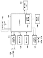
図1は、本発明の実施形態に係る焦点検出センサを用いた光学機器の一例として、カメラの構成を示すブロック図である。なお、図1においては、カメラの構成のうち、自動焦点検出に係る構成以外の構成については省略している。
<First Embodiment>
FIG. 1 is a block diagram illustrating a configuration of a camera as an example of an optical apparatus using a focus detection sensor according to an embodiment of the present invention. In FIG. 1, configurations other than those related to automatic focus detection are omitted from the configuration of the camera.
スイッチ103は、不図示のレリーズボタンの操作によってON、OFFする2つのスイッチSW1及びSW2を有する。ここで、スイッチSW1はレリーズボタンの第1ストローク(半押し)操作でONし、スイッチSW2はレリーズボタンの第2ストローク(全押し)操作でONするものとする。スイッチSW1のONにより焦点検出動作を含む撮影準備動作の開始が指示され、スイッチSW2のONにより撮影動作の開始が指示される。
The
レンズ通信回路104は、カメラCPU100の制御に従って不図示の撮像レンズとレンズ信号114を通信し、撮像レンズに含まれるフォーカスレンズや絞り等を制御する。シャッタ制御回路107は、カメラCPU100の制御に従って不図示のシャッタ機構が有する電磁石117a、117bの通電時間を制御することで、シャッタの開閉を制御する。
The
測距点選択スイッチ108は、不図示の選択ボタンの操作により、撮影画面内に配置された複数の測距点(焦点検出領域)のうち任意の測距点を選択する。なお、撮影画面における測距点位置については後述する。
The distance measuring
カメラCPU100はプログラムを格納したROM、変数を記憶するためのRAM、諸パラメータを記憶するためのEEPROM(電気的消去、書き込み可能メモリ)を有し、プログラムに基づいて各部を制御することにより、カメラの全体的な動作を制御する。また、カメラCPU100は、被写体判定部102を有し、測距点選択スイッチ108の情報から主要被写体位置を判定し、焦点検出センサ101を制御する。
The
カメラCPU100はSW2がONすると、測光センサ106を制御して被写体の輝度を検出し、被写体輝度に応じて不図示の撮像レンズの絞り値やシャッタスピード等の撮像条件を決定する。そして、カメラCPU100はレンズ通信回路104とシャッタ制御回路107とを通じ、決定した撮像条件で撮像センサ105を露光する。そして、カメラCPU100は撮像センサ105で蓄積された電荷を読み出し、公知の画像処理を適用することにより、撮影画像データを生成し、不図示の記録媒体に記録する一連の撮影動作を実行する。
When SW2 is turned on, the
(カメラの光学系部品配置)
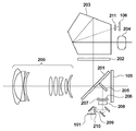
図2は、本実施形態におけるカメラの光学部品とその配置例を示す図であり、カメラの側方から見た光学部品の配置例を示している。なお、図2では撮像レンズ200を示しているが、撮像レンズ200を備えたレンズユニットが着脱可能であってもよく、カメラと一体的に構成されていなくても構わない。
(Camera optical parts placement)
FIG. 2 is a diagram illustrating the optical components of the camera and an arrangement example thereof according to the present embodiment, and illustrates an arrangement example of the optical components as viewed from the side of the camera. 2 shows the
撮像レンズ200を介して入射した被写体からの光束の大部分はクイックリターンミラー201により上方へ反射され、ファインダスクリーン202上に結像する。撮影者はファインダスクリーン202に結像した被写体像をペンタプリズム203及び接眼レンズ204を介して観察する。ファインダスクリーン202は、透過型液晶で構成されており、撮影に係わる各種情報を撮影画面に重ねてファインダ表示することができる。本実施形態では、撮影情報として測距点選択スイッチ108の操作により選択された測距点を表示する。
Most of the light beam from the subject incident through the
接眼レンズ204の上方には測光結像レンズ211と測光センサ106が設けられる。測光センサ106は、ファインダスクリーン202に結像した被写体像を測光結像レンズ211を通じて受光することで、被写体輝度を測定することができる。なお、図2における測光結像レンズ211と測光センサ106の組み合わせ及び配置は例示であり、被写体輝度が測定可能であれば、構成や配置は図2に示すものと異なっていても良い。
A
撮像レンズ200から入射した光束の一部はクイックリターンミラー201を透過し、後方のサブミラー205により、下方にある焦点検出光学系に導かれる。焦点検出光学系に入射した光束は、視野マスク206、赤外カットフィルタ207、フィールドレンズ208、絞り209、二次結像レンズ210を経て、焦点検出センサ101上に結像する。結像した像を焦点検出センサ101で光電変換して得られる像信号の位相差に基づいて、撮像レンズ200の焦点状態(デフォーカス量)を検出することができる。
Part of the light beam incident from the
なお、スイッチSW2がONになり撮影動作を行う場合、クイックリターンミラー201上方に回転してサブミラー205と共に光路から退避し、不図示のシャッタが開くことで、撮像レンズ200から入射した被写体像の光束で撮像センサ105が露光される。
Note that when the switch SW2 is turned on to perform a photographing operation, the light beam of the subject image incident from the
(ラインセンサの配置と測距点との位置関係)
焦点検出センサ101に含まれる複数のラインセンサと画面内の測距点との位置関係について、図3を用いて説明する。図3(a)は焦点検出センサ101におけるラインセンサの配置例を示す図である。ラインセンサ対101−1〜18はそれぞれ一対のセンサアレイから構成され、各センサアレイはセンサとしての光電変換素子が複数、一列に配置された構成を有し、各画素の出力から信号像を得ることができる。そして、各センサアレイ対から得られた信号像の位相差から、撮像レンズの焦点状態(デフォーカス量)を検出することができる。センサアレイ対は二次結像レンズ210などの焦点検出光学系により、視野(画面)上のほぼ同じ領域に投影され、この領域が測距点を形成する。
(Positional relationship between line sensor layout and ranging points)
A positional relationship between a plurality of line sensors included in the
図3(b)は、図3(a)に示した焦点検出センサ101に対応する、ファインダ画面における測距点とラインセンサ対との位置関係の例を示す図である。ファインダ画面300(視野)には、9つの測距点が横一列に並んで配置されている。測距点301は、ラインセンサ対101−1とラインセンサ対101−2が投影された領域により形成される。測距点302〜測距点309も同様であり、各測距点は、2つのラインセンサ対が投影された領域により形成される。
FIG. 3B is a diagram illustrating an example of a positional relationship between a distance measuring point and a line sensor pair on the finder screen corresponding to the
なお、図3に示すように、本実施形態では隣接するセンサアレイを半ピッチ分ずらして配置している。一般的に、被写体の空間周波数が高い場合、センサアレイの画素位置と被写体のコントラストの位相との関係により、検出されるデフォーカス量に誤差が生じる。この誤差を低減するため、半画素ピッチずらして配置した2組のセンサアレイ対で得られた2つのデフォーカス量の平均値を用いている。 As shown in FIG. 3, in this embodiment, adjacent sensor arrays are arranged with a half-pitch shift. Generally, when the spatial frequency of the subject is high, an error occurs in the detected defocus amount due to the relationship between the pixel position of the sensor array and the phase of the contrast of the subject. In order to reduce this error, an average value of two defocus amounts obtained by two pairs of sensor arrays arranged with a half-pixel pitch shift is used.
なお、図3では、上下方向にシフトしたラインセンサ対を18組配置し、9つの測距点を構成する例を示しているが、ラインセンサ対の配置はこれに限るものではない。例えば、左右方向にシフトしたり、上下方向と左右方向を組み合わせて配置しても良く、また、ラインセンサ対の数も18組より多くても少なくても良い。 3 shows an example in which 18 line sensor pairs shifted in the vertical direction are arranged to form nine distance measuring points, the arrangement of the line sensor pairs is not limited to this. For example, it may be shifted in the left-right direction, or may be arranged by combining the up-down direction and the left-right direction, and the number of line sensor pairs may be more or less than 18.
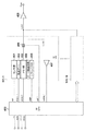
図4は、本実施形態に係る焦点検出センサ101の構成例を示すブロック図である。図4では、図3(a)に示したラインセンサ対101−1〜101−18のうち、ラインセンサ対101−1についてのみ詳細に示しているが、ラインセンサ対101−2〜101−18についても、同様の構成を有する。
FIG. 4 is a block diagram illustrating a configuration example of the
焦点検出センサ101は、自動焦点検出用CPU(AFCPU)400を有し、AFCPU400は各センサアレイ対の蓄積動作及び像信号の読出し動作を制御している。図4においてセンサ部401は、ラインセンサ対101−1を形成する一対のセンサアレイを構成する光電変換素子群(画素群)に相当する。AFCPU400からrst信号が出力(すなわち、信号の値が1に)されると、センサ部401の各画素がリセットされる。メモリ部403(保持部)は、センサ部401の各画素で光電変換された信号電荷を画素毎に積分して一時的に記憶し、AFCPU400からrstm_1信号が出力される(すなわち、信号の値が1に)されると、リセットされる。センサ部401とメモリ部403の間には転送ゲート402が設けられており、AFCPU400からtrans_1信号が出力(すなわち、信号の値が1に)されると、転送ゲートが開いてセンサ部401からメモリ部403に電荷が転送される。また、ピーク検出回路404は、メモリ部403に一時記憶された積分された電荷の信号レベルの最大値(p−out)を検出し、コンパレータ407に出力する。シフトレジスタ405は、メモリ部403から積分した電荷を読み出す画素を選択する。
The
コンパレータ407は、ピーク検出回路404で検出した、信号レベルの最大値(p−out)と所定の電圧VRとを比較し、比較結果を示すcomp信号をAFCPU400に出力する。comp信号はp−out>VRであれば1、それ以外は0をとる信号である。なお、所定の電圧VRは画素飽和電圧であり、p−out>VRで蓄積動作を終了すべきであることを示す値に設定する。
The
シフトレジスタ405は、AFCPU400からシフトパルスであるshift信号が入力されると、メモリ部403の出力を画素ごとに選択する。そして、AFCPU400からのsel_1信号によりアナログスイッチ406がONの間、メモリ出力を出力アンプ408の入力に出力する。出力アンプ408は適切なゲインでVout端子より画素信号を出力する。
When the shift signal that is a shift pulse is input from the
また、AFCPU400は、不図示のレジスタを有する。このレジスタは、AFCPU400が有する通信端子であるcs、sclk、miso、mosi端子を用いたシリアル通信により、外部から読み出しや書き込み可能である。レジスタの値を外部(例えばカメラCPU100)から設定することにより、焦点検出センサ101の動作を制御することができる。本実施形態において、AFCPU400は焦点検出センサ101の2種類の蓄積タイプを制御可能であるものとする。
The
(蓄積動作)
次に、本実施形態における焦点検出センサ101の蓄積動作について、図5および図6のフローチャートを用いて詳しく説明する。
(Accumulation operation)
Next, the accumulation operation of the
まず、第1タイプの蓄積動作(第2の蓄積方法)を行うための制御方法を図5のフローチャートを用いて詳しく説明する。S501でカメラCPU100からAFCPU400のレジスタstrtが1に設定されると、AFCPU400は焦点検出センサ101における蓄積動作を開始させる。
First, a control method for performing the first type accumulation operation (second accumulation method) will be described in detail with reference to the flowchart of FIG. When the register strt of the
S502でAFCPU400は、ラインセンサ対101−nの初期リセット動作を行う。AFCPU400は自身のレジスタを0にクリアした後、trans_n信号、rst信号、rstm_n信号を出力(すなわち、信号の値を1に)し、センサ部401とメモリ部403の電荷をクリアする。
In S502, the
S503でAFCPU400は、rst信号、rstm_n信号の出力を終了(すなわち、信号の値を0に)して、センサ部401とメモリ部403のリセットを完了させ、蓄積を開始する。なお、AFCPU400は、trans_n信号についてはS502から継続して出力しているので、転送ゲート402はONしており、蓄積中にセンサ部401で発生した信号電荷は転送ゲート402を通じてメモリ部403で蓄積され、電圧に変換される。
In step S503, the
S504でAFCPU400は、電荷蓄積が十分行われたか否かを、コンパレータ407の出力するcomp信号の値によって判定する。ラインセンサ対101−nの蓄積が十分であり、電荷蓄積を終了すべき場合には、p−out>VRとなり、コンパレータ407からcomp=1が出力される。S504でcomp信号の値が1であれば、AFCPU400はS506以降の蓄積終了処理を実行する。一方、comp=0が出力されている場合、p−out≦VRで蓄積が不十分であるので、S505に進み、AFCPU400は、自身のレジスタstp_nの値を判定する。このレジスタstp_nの値は外部(例えば、カメラCPU100)からAFCPU400への通信により設定される。なお、第1タイプの読み出しでは、レジスタstp_nは、後述する図7のS708において蓄積時間が打ち切り時間に達した場合に1が設定されるもので、詳細は後述する。レジスタstp_nが1であればS506に進み、1でなければ、AFCPU400は、comp信号=1となるまでS504における判定処理を継続する。
In step S <b> 504, the
S506でAFCPU400は、trans_n信号の出力を終了し、転送ゲート402をOFFする。これにより、trans_n信号が出力されている間にメモリ部403に積分された蓄積電荷が記憶される。
In step S506, the
S507でAFCPU400は、蓄積終了フラグを示すレジスタtr_nに1を設定し、蓄積動作を終了する。外部(例えば、カメラCPU100)からの通信でレジスタtr_nをモニタすることで、ラインセンサ対101−nの蓄積が終了したことを知ることができる。
In S507, the
次に、第2タイプの蓄積動作(第1の蓄積方法)を行うための制御方法を図6のフローチャートを用いて詳しく説明する。S601でカメラCPU100からAFCPU400のレジスタstrtが1に設定されると、AFCPU400は焦点検出センサ101における蓄積動作を開始させる。
Next, a control method for performing the second type accumulation operation (first accumulation method) will be described in detail with reference to the flowchart of FIG. When the register strt of the
S602でAFCPU400は、ラインセンサ対101−nの初期リセット動作を行う。AFCPU400は自身のレジスタを0にクリアした後、trans_n信号、rst信号、rstm_n信号を出力(すなわち、信号の値を1に)し、センサ部401とメモリ部403の電荷をクリアする。
In step S602, the
S603でAFCPU400は、trans_n信号、rst信号の出力を終了(信号の値を0に)する。これにより、センサ部401のリセットが完了し、これよりセンサ部401で発生した蓄積電荷はセンサ部401で蓄積される。ここでは、AFCPU400は、trans_n信号の出力を終了しているため転送ゲート402がOFFしており、さらにrstm_n信号の出力は継続されているので、センサ部401における電荷蓄積中もメモリ部403はリセットされ続ける。
In step S603, the
S604でAFCPU400は、自身のレジスタstp_nの値を判定する。第2タイプの蓄積動作では、電荷蓄積中でもメモリ部403はリセット中のため、p−out>VRにはならず、comp信号によって蓄積停止を判定することはできない。そこで、外部(例えば、カメラCPU100)からAFCPU400への通信により、AFCPU400のレジスタstp_nの値を設定することで、外部から蓄積動作の終了を制御する。なお、レジスタstp_nは、後述する図7のS705またはS708において設定されるもので、詳細は後述する。ここでは、レジスタstp_nの値が1であればAFCPU400は蓄積終了と判定し、S605以降の処理に移行する。一方、レジスタstp_nの値が0の場合、AFCPU400はレジスタstp_nの値の判定をS604で継続して実行する。
In step S604, the
S605でAFCPU400は、rstm_n信号の出力を終了し、メモリ部403のリセットを完了する。その後、AFCPU400は、trans_n信号の出力を開始して転送ゲート402をONにし、ラインセンサ対101−nのセンサ部401で積分された蓄積電荷をメモリ部403へ転送する。電荷蓄積期間中、センサ部401からメモリ部403への電荷転送は行われず、さらに蓄積が終了して蓄積電荷が転送される直前まで、メモリ部403はリセットされ続けている。そのため、センサ部401における電荷蓄積期間中にメモリ部403で発生するノイズはメモリ部403に蓄積されない。
In step S605, the
S606でAFCPU400は、trans_n信号の出力を終了し、転送ゲート402をOFFする。これにより、S605で転送した電荷をメモリ部403に記憶する。S607では、AFCPU400内の蓄積終了フラグを示すレジスタtr_nに1を設定する。
In S606, the
このように、本実施形態において、AFCPU400は、2種類の異なるタイプの蓄積動作を行うことができる。さらに、外部(例えば、カメラCPU100)からの通信でAFCPU400のレジスタ値を設定することで、ラインセンサ対毎に蓄積タイプ(第1タイプか第2タイプか)に切替えることができる。
Thus, in this embodiment, the
図5及び図6のフローチャートでは、任意のラインセンサ対101−nの蓄積動作の説明をしたが、ラインセンサ対101−1〜18に対して同様の蓄積動作が行われる。AFCPU400は、ラインセンサ対101−1〜18用のレジスタtr_1〜tr_18、stp_1〜stp_18を有し、またラインセンサ対101−1〜18用の信号線も有している。
In the flowcharts of FIGS. 5 and 6, the accumulation operation of an arbitrary line sensor pair 101-n has been described, but the same accumulation operation is performed on the line sensor pairs 101-1 to 101-18. The
(カメラの動作)
次に、上述した焦点検出センサ101を備える本第1の実施形態におけるカメラの動作について、図7のフローチャートを用いて詳しく説明する。この動作は、図1で示したカメラのスイッチSW1がONしたことにより、カメラCPU100が実行する。
(Camera operation)
Next, the operation of the camera according to the first embodiment including the
S701でカメラCPU100は内部の被写体判定部102により、主要被写体位置を判定する。ここでは、測距点選択スイッチ108の情報、つまり選択された測距点を主要被写体位置と判断する。
In step S <b> 701, the
S702でカメラCPU100は、S701で判定した主要被写体位置に基づいて、焦点検出センサ101のラインセンサ対101−1〜18のそれぞれについて蓄積タイプ(第1タイプか第2タイプか)を決定する。そして、カメラCPU100は、焦点検出センサ101のAFCPU400と通信し、AFCPU400のレジスタ値を設定することで、ラインセンサ対101−1〜18それぞれの蓄積タイプを設定する。
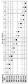
In S702, the
ここで蓄積タイプの決定方法について、図8を参照して詳細に説明する。図8は、主要被写体位置と各ラインセンサ対101−nの蓄積タイプの対応表である。図8において、記号△と▲は第1タイプ、記号○と●は第2タイプを示す。主要被写体位置である選択された測距点を形成するラインセンサ対は第2タイプ、その隣接したラインセンサ対は第1タイプに設定する。△と▲あるいは○と●以外のラインセンサ対については、蓄積制御を禁止する。 Here, the accumulation type determination method will be described in detail with reference to FIG. FIG. 8 is a correspondence table between the main subject positions and the accumulation types of the respective line sensor pairs 101-n. In FIG. 8, symbols Δ and ▲ indicate the first type, and symbols ○ and ● indicate the second type. The pair of line sensors forming the selected distance measuring point which is the main subject position is set to the second type, and the pair of adjacent line sensors is set to the first type. Accumulation control is prohibited for line sensor pairs other than △ and ▲ or ○ and ●.
図7に戻り、S703でカメラCPU100は、焦点検出センサ101のAFCPU400と通信し、AFCPU400のレジスタstrtに1を設定することにより、AF蓄積動作を開始させる。これにより、図5あるいは図6を参照して説明した蓄積動作を開始させる。また、カメラCPU100は、自身の内部にある不図示のカウンタにより、蓄積時間Tの計測を開始する。
Returning to FIG. 7, in step S <b> 703, the
S704でカメラCPU100は、新たに蓄積動作が終了したラインセンサ対があるか否かを、焦点検出センサ101のAFCPU400のレジスタtr_n(n=1〜18)の値から判別する。ここでは、S702の動作で第1タイプに設定したラインセンサ対についてのみ蓄積終了判定する。蓄積終了したラインセンサ対があれば、S705へ移行する。一方、蓄積終了したラインセンサ対が無ければ、S707へ移行する。
In step S <b> 704, the
S705でカメラCPU100は、S704で判定した蓄積終了したラインセンサ対の近傍のラインセンサ対について蓄積を停止させる。ここでは、第1タイプに設定した△に対応したラインセンサ対の蓄積が終了した場合、第2タイプに設定した○に対応したラインセンサ対の蓄積を停止させる。また、第1タイプに設定した▲に対応したラインセンサ対が蓄積終了した場合、第2タイプに設定した●に対応したラインセンサ対の蓄積を停止させる。この際、カメラCPU100は、焦点検出センサ101のAFCPU400と通信し、AFCPU400のレジスタstp_n(n=1〜18)の内、蓄積停止させるラインセンサ対に対応したレジスタに1を設定することにより、AF蓄積動作を停止させる。
In step S <b> 705, the
S706でカメラCPU100は、蓄積を許可したラインセンサ対の全てについて蓄積が終了している場合は、カメラCPU100はS709の信号読み出し動作を行う。一方、カメラCPU100は蓄積終了していないラインセンサ対がある場合は、S704へ戻る。
In step S <b> 706, when the accumulation of all the line sensor pairs permitted to be accumulated has been completed, the
S707では、カメラCPU100は、自身のカウンタによる蓄積時間Tの判定を行う。蓄積時間T≧Tmの場合は、焦点検出センサ101の蓄積時間が打切り時間Tmに達しているので、S708に進む。一方、蓄積時間T<Tmの場合は、S704へ戻り蓄積動作を継続する。
In S707, the
S708でカメラCPU100は、AFCPU400と通信し、蓄積を許可したラインセンサ対の内、蓄積を終了していないラインセンサ対に対応するAFCPU400のレジスタstp_n(n=1〜18)に1を設定し、全ラインセンサ対の蓄積を終了させる。
In step S <b> 708, the
S709でカメラCPU100は、AFCPU400と通信し、主要被写体位置の測距点を形成するラインセンサ対で得られた画素信号を読み出す。AFCPU400は、読み出し指示に応じてshift信号を出力し、シフトレジスタ405を駆動して信号を読み出し、カメラCPU100に出力する。カメラCPU100は、焦点検出センサ101から出力される画素信号を順次A/D変換し、不図示のRAMに記憶する。
In step S <b> 709, the
S710でカメラCPU100は、S709で得たラインセンサ対の画素信号から、デフォーカス量を算出する。ここで、同じ測距点を構成する2組のラインセンサ対からの画素信号に基づいて得られたデフォーカス量の演算結果は、平均や重み付け平均するなどして最終結果とする。
In S710, the
S711でカメラCPU100は、S710で算出したデフォーカス量が所望の範囲内、例えば1/4Fδ以内(F:レンズの絞り値、δ:定数(20μm))であれば合焦と判断する。具体的にはカメラCPU100は例えば、レンズの絞り値F=2.0であれば、デフォーカス量が10μm以下なら合焦と判断し、処理をS713へ移行する。
In step S711, the
一方、デフォーカス量が1/4Fδより大きいならば、S712でカメラCPU100は、S710で算出したデフォーカス量に対応するフォーカスレンズ駆動をレンズ通信回路104を介して撮像レンズ200に指示する。そして、カメラCPU100は処理をS702に戻し、合焦状態と判断されるまで前述の動作を繰り返す。
On the other hand, if the defocus amount is greater than ¼Fδ, in step S712, the
S713でカメラCPU100はスイッチSW2の状態を検出し、ONの場合は、S715からの撮影動作を開始する。一方、S713でスイッチSW2がOFFの場合、カメラCPU100はS714でスイッチSW1の状態を検出する。S714でSW1が依然としてONであればカメラCPU100はS702からの処理を繰り返し、SW1がOFFになっていれば、AF動作を終了する。
In S713, the
S715で、カメラCPU100は測光センサ106を用いて検出した測光値から被写体輝度BVを求め、被写体輝度BVを設定されたISO感度SVと加算して露出値EVを求める。そして、カメラCPU100は、例えば予め定められたプログラム線図を用いるなど公知の方法で、露出値EVに対応する絞り値AVおよびシャッタ速度TVを決定する。カメラCPU100は、クイックリターンミラー201を撮像光路から退避させると同時に、レンズ通信回路104を通じて撮像レンズ200に対し、絞りを決定した絞り値AVに対応する開口とするように指示する。その後、クイックリターンミラー201が撮像光路から完全に退避する。
In S715, the
S716で、カメラCPU100はシャッタ制御回路107を介して電磁石117a、117bの通電時間よりシャッタスピードを制御し、撮像センサ105を露光する。S717でカメラCPU100は、クイックリターンミラー201を撮像光路中の位置に戻し、撮影動作を終了する。なお、撮像センサ105で蓄積された像信号の処理(いわゆる現像処理や記録媒体への記録処理)は、公知の処理でよいため、ここでは説明を省略する。
In step S <b> 716, the
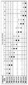
ここで、図9を参照して具体例を説明する。図9(a)は、測距点選択スイッチ108により測距点303が選択された場合の、各ラインセンサ対の蓄積タイプの設定を示す。図8の対応表から、測距点303が選択された場合は、斜線で表したラインセンサ対101−5と101−6を第2タイプに設定する。ただし、第2タイプに設定されたラインセンサ対は、蓄積中に信号モニタができない。そこで、蓄積モニタ用として、隣接する測距点302、304を構成する一部のラインセンサ対101−4と101−7を第1タイプに設定する。第1タイプに設定されたラインセンサ対は、蓄積中に信号モニタができるため、焦点検出センサ101内で被写体輝度に応じて適切な蓄積制御が行える。そこで、本第1の実施形態では、ラインセンサ対101−4の蓄積が終了したタイミングでラインセンサ対101−5、ラインセンサ対101−7が終了したタイミングでラインセンサ対101−6の蓄積を終了する。
Here, a specific example will be described with reference to FIG. FIG. 9A shows the setting of the accumulation type of each line sensor pair when the
図9(b)は測距点303から測距点304に移動選択された場合の各ラインセンサ対の蓄積タイプの設定を示す。図8の対応表から、測距点304が選択された場合は、斜線で表したラインセンサ対101−7と101−8を第2タイプに設定する。更に、蓄積モニタ用として、隣接する測距点303、305を構成する一部のラインセンサ対101−6と101−9を第1タイプに設定する。ラインセンサ対101−6の蓄積が終了したタイミングでラインセンサ対101−7、ラインセンサ対101−9の蓄積が終了したタイミングでラインセンサ対101−8の蓄積を終了する。
FIG. 9B shows the setting of the accumulation type of each line sensor pair when moving from the
図9(a)ではラインセンサ対101−7の蓄積動作はモニタ用である第1タイプであったが、図9(b)では焦点検出用の第2タイプに変わる。一方、図9(a)ではラインセンサ対101−6の蓄積動作は焦点検出用の第2タイプであったが、図9(b)ではモニタ用の第1タイプに変わる。このように、選択された測距点に応じて、ラインセンサ対の蓄積タイプが変化する。 In FIG. 9A, the accumulation operation of the line sensor pair 101-7 is the first type for monitoring, but in FIG. 9B, it is changed to the second type for focus detection. On the other hand, in FIG. 9A, the accumulation operation of the line sensor pair 101-6 is the second type for focus detection, but in FIG. 9B, it is changed to the first type for monitoring. Thus, the accumulation type of the line sensor pair changes according to the selected distance measuring point.
上記の通り本第1の実施形態によれば、電荷蓄積期間中に第1タイプのラインセンサ対で蓄積電荷を監視することができるため、電荷蓄積期間を適切に制御できるとともに、第2タイプのラインセンサ対からは質の高い像信号を得ることが可能である。特に被写体輝度が低い場合の画素信号のSN比低下を抑制することができる。また、モニタ専用のラインセンサ対を配置する必要が無いので、焦点検出センサの設計が容易になる。 As described above, according to the first embodiment, since the accumulated charge can be monitored by the first type line sensor pair during the charge accumulation period, the charge accumulation period can be appropriately controlled, and the second type It is possible to obtain a high-quality image signal from the line sensor pair. In particular, it is possible to suppress a decrease in the SN ratio of the pixel signal when the subject brightness is low. Further, since it is not necessary to arrange a pair of line sensors dedicated to the monitor, the focus detection sensor can be easily designed.
なお、本第1の実施形態では第2タイプに設定したラインセンサ対の蓄積を終了するタイミングについてはカメラCPU100が制御しているが、焦点検出センサ101内のAFCPU400が制御してもよい。
In the first embodiment, the
また、本第1の実施形態では、コンパレータ407は、ピーク検出回路404により検出された信号レベルの最大値(p−out)と所定の電圧VRとを比較し、p−out>VRの場合にcomp信号として1、それ以外は0を出力する場合について説明した。しかしながら、本発明はこれに限るものではなく、例えば、メモリ部403に蓄積された信号レベルの最大値と最小値との差(コントラスト)を予め決められた値と比較し、超えた場合に、comp信号として1、それ以外は0を出力するようにしてもよい。
In the first embodiment, the
<第2の実施形態>
次に、本発明の第2の実施形態について説明する。第2の実施形態では、主要被写体判定として顔情報を使用する例について説明する。なお、第1タイプと第2タイプの蓄積タイプを切替える点は第1の実施形態と同様であり、焦点検出光学系の構成についても第1の実施形態と同じでよいため、重複する説明は省略する。
<Second Embodiment>
Next, a second embodiment of the present invention will be described. In the second embodiment, an example in which face information is used as main subject determination will be described. Note that the point of switching between the first type and the second type of accumulation type is the same as in the first embodiment, and the configuration of the focus detection optical system may be the same as in the first embodiment. To do.
図10は、第2の実施形態に係る焦点検出センサを用いた光学機器の一例としてのカメラの構成例を示すブロック図である。なお、図10のカメラの構成のうち、測光センサ109と顔検出部110以外は図1と同じであるため、同じ参照番号を付して説明を省略する。
FIG. 10 is a block diagram illustrating a configuration example of a camera as an example of an optical apparatus using the focus detection sensor according to the second embodiment. 10 is the same as FIG. 1 except for the
測光センサ109は、測光や被写体認識のための被写体像を撮像するための多画素エリアセンサであり、画素部には、R(赤)、G(緑)、B(青)の原色フィルターが設けられている。これにより、被写体像のRGB信号を出力することができる。カメラCPU100は測光センサ109を制御することで、被写体の輝度を検出し、不図示の撮影レンズの絞り値やシャッタスピードを決定する。さらに、測光センサ109で得られた画像から被写体の輝度分布情報や色情報をCPU100内の顔検出部110で処理することで、予め記憶してある人物の特徴情報から画像中に存在する主要被写体位置を検出する。
The
(カメラの動作)
図10に示すカメラの本第2の実施形態における動作例について、図11のフローチャートを用いて詳しく説明する。この動作は、図10で示したカメラのスイッチSW1がONしたことにより、カメラCPU100が実行する。図11に示す処理では、顔検出部110の検出結果に応じて被写体判定部102が主要被写体位置を決定するところが、上述した図7に示す処理と異なる。なお、図7を参照して第1の実施形態で上述した処理と同様の処理には同じステップ番号を付し、適宜説明を省略する。
(Camera operation)
An example of the operation of the camera shown in FIG. 10 in the second embodiment will be described in detail with reference to the flowchart of FIG. This operation is executed by the
まず、S1101でカメラCPU100内部の顔検出部110により画面中に存在する顔を検出し、さらに被写体判定部102により主要被写体位置を判定する。ここでは、測光センサ109で得られた画像から被写体の輝度分布情報や色情報から人物の顔を検出し、その顔位置を主要被写体位置とする。
First, in S1101, the
S1102でカメラCPU100は、S1101で判定した主要被写体位置の情報から、焦点検出センサ101のラインセンサ対101−1〜18のそれぞれについて蓄積タイプ(第1タイプか第2タイプか)を決定する。そして、カメラCPU100は、焦点検出センサ101のAFCPU400と通信し、AFCPU400のレジスタ値を設定することで、ラインセンサ対101−1〜18の蓄積タイプを設定する。
In S1102, the
ここで蓄積タイプの決定方法について、図12で詳細に説明する。図12は、主要被写体位置と各ラインセンサ対101−nの蓄積タイプの対応表である。図12において、記号△と▲は第1タイプ、記号○と●は第2タイプとする。図12では、選択された測距点に対応したラインセンサ対を第2タイプに設定する。さらに、その隣接した測距点を形成する2つのラインセンサ対のうち、片方のラインセンサ対を第1タイプ、他方を第2タイプに設定する。△と▲あるいは○と●以外のラインセンサ対については、蓄積制御を禁止する。このように設定することで、主要被写体が選択された測距点位置から隣接した測距点に移動した場合でも、第2タイプに設定したラインセンサ対により像信号を取得することができる。 Here, the storage type determination method will be described in detail with reference to FIG. FIG. 12 is a correspondence table between the main subject positions and the accumulation types of the respective line sensor pairs 101-n. In FIG. 12, symbols Δ and ▲ are the first type, and symbols ○ and ● are the second type. In FIG. 12, the line sensor pair corresponding to the selected distance measuring point is set to the second type. Further, of the two line sensor pairs forming the adjacent distance measuring points, one line sensor pair is set to the first type and the other is set to the second type. Accumulation control is prohibited for line sensor pairs other than △ and ▲ or ○ and ●. By setting in this way, even when the main subject moves from the selected distance measuring point position to the adjacent distance measuring point, the image signal can be acquired by the line sensor pair set to the second type.
S1102で蓄積タイプを決定した後、S703〜S708では、図7を参照して説明した蓄積処理と同様にして蓄積処理を行う。 After the storage type is determined in S1102, the storage process is performed in S703 to S708 in the same manner as the storage process described with reference to FIG.
蓄積許可した全ラインセンサ対の蓄積を終了すると、S1109でカメラCPU100は内部の顔検出部110により、再度、主要被写体位置を判定する。この動作により、被写体が動いている場合などで、主要被写体位置がS1101で決定した測距点位置から近傍の測距点に移動しても対応できる。
When the accumulation of all the line sensor pairs permitted to accumulate is completed, the
S1110でカメラCPU100は、AFCPU400と通信し、S1109検出された主要被写体位置に対応した測距点を形成するラインセンサ対のうち第2タイプに設定されたラインセンサ対で得られた画素信号を読み出す。S1109で検出した主要被写体位置がS1101で検出した主要被写体位置と異なる、つまり、隣接した測距点に移動した場合でも、第2タイプに設定したラインセンサ対が1本存在する。AFCPU400は、読み出し指示に応じてshift信号を出力し、シフトレジスタ405を駆動して信号を読み出し、カメラCPU100に出力する。カメラCPU100は、焦点検出センサ101から出力される画素信号を順次A/D変換し、不図示のRAMに記憶する。
In step S <b> 1110, the
S1111でカメラCPU100は、S1110で得たラインセンサ対の画素信号から、デフォーカス量を算出する。ここで、S1110で読出したラインセンサ対が2本ある場合は、得られたデフォーカス量の演算結果を平均や重み付け平均するなどして最終結果とする。
In S1111, the
S711〜S717の動作については、図7を参照して第1の実施形態で説明した処理と同様であるので、ここでは説明を省略する。 Since the operations in S711 to S717 are the same as those described in the first embodiment with reference to FIG. 7, the description thereof is omitted here.
ここで、図13を参照して、顔検出位置が測距点306である場合のラインセンサの蓄積タイプの設定について説明する。図13(a)は撮影画面例を示している。測距点301から測距点309のうち左から6番目の測距点306に顔が存在している。この場合のラインセンサ対と測距点の位置関係を図13(b)に示す。図12の対応表から、斜線で表したラインセンサ対101−9、101−11、101−12、101−14を第2タイプに設定する。ただし、第2タイプに設定されたラインセンサ対は、蓄積中に信号モニタができない。そこで、蓄積モニタ用として、ラインセンサ対101−9と101−11の間のラインセンサ対101−10と、ラインセンサ対101−12と101−14の間のラインセンサ対101−13を第1タイプに設定する。第1タイプに設定されたラインセンサ対は、蓄積中に信号モニタができるため、焦点検出センサ101内で被写体輝度に応じて適切な蓄積制御を行うことができる。ラインセンサ対101−10の蓄積が終了したタイミングで隣接するラインセンサ対101−9とラインセンサ対101−11の蓄積を終了する。また、ラインセンサ対101−13が終了したタイミングで隣接するラインセンサ対101−12とラインセンサ対101−14の蓄積を終了する。
Here, with reference to FIG. 13, setting of the accumulation type of the line sensor when the face detection position is the
以上説明したように、主要被写体位置が最初に検出した測距点位置から別の測距点に移動した場合でも、像信号の検出が可能となる。 As described above, it is possible to detect an image signal even when the main subject position moves from the first distance measuring point position to another distance measuring point.
なお、第2の実施形態では、主要被写体の判定として人物の顔を用いているが、顔以外の特徴を検出してもよい。 In the second embodiment, a person's face is used for determining the main subject, but features other than the face may be detected.
また、上述した第1及び第2の実施形態では、焦点検出センサ101が複数のラインセンサ対により構成されるものとして説明したが、本発明はラインセンサに限られるものではない。例えば、複数の光電変換素子を2次元に配置した光電変換素子群を測距点に対応する位置に配した構成としてもよい。
In the first and second embodiments described above, the
以上説明した実施形態では、スチルカメラにおける実施形態を説明したが、本発明はこれに限るものではなく、焦点調節を行う様々な撮像装置に適用することができる。例えば、動画撮影を行うカムコーダ(ムービーカメラ)、各種検査カメラ、監視カメラ、内視鏡カメラ、ロボット用カメラ等に応用しても良い。 In the above-described embodiment, the embodiment of the still camera has been described. However, the present invention is not limited to this, and can be applied to various imaging apparatuses that perform focus adjustment. For example, the present invention may be applied to a camcorder (movie camera) that performs moving image shooting, various inspection cameras, surveillance cameras, endoscope cameras, robot cameras, and the like.
100 カメラCPU
101 焦点検出センサ
101−1〜101−18 ラインセンサ
102 被写体判定部
105 撮像センサ
106 測光センサ
108 測距点選択スイッチ
110 顔検出部
301〜308 測距点
400 AFCPU
401 センサ部
403 メモリ部
404 ピーク検出回路
100 Camera CPU
DESCRIPTION OF
401
Claims (11)
前記複数の焦点検出領域のいずれかを選択する選択手段と、
前記複数の光電変換素子群から転送手段を介して転送される電荷をそれぞれ保持するための複数の保持手段と、
前記光電変換素子群ごとの蓄積方法を前記転送手段を制御することで、前記光電変換素子群で発生した電荷を該光電変換素子群において蓄積する第1の蓄積方法と、前記光電変換素子群で発生した電荷を前記保持手段に転送して蓄積する第2の蓄積方法とのいずれかに設定する設定手段と、
前記保持手段に保持された電荷の信号レベルを、前記第2の蓄積方法に設定された前記光電変換素子群ごとにモニタするモニタ手段と、
前記モニタ手段がモニタした信号レベルに基づいて前記光電変換素子群ごとの蓄積終了を制御する制御手段と、を有し、
前記設定手段は、前記複数の光電変換素子群のうち、前記選択手段により選択された焦点検出領域に対応する光電変換素子群の蓄積方法を前記第1の蓄積方法に設定し、前記第1の蓄積方法に設定された光電変換素子群に隣接する光電変換素子群の蓄積方法を前記第2の蓄積方法に設定し、
前記制御手段は、前記モニタ手段がモニタした前記第2の蓄積方法に設定された光電変換素子群の信号レベルに基づいて、当該光電変換素子群及び隣接する前記第1の蓄積方法に設定された光電変換素子群における電荷の蓄積終了を制御することを特徴とする焦点検出装置。 A plurality of photoelectric conversion element groups that correspond to a plurality of focus detection regions and generate charges according to incident light;
Selecting means for selecting any of the plurality of focus detection areas;
A plurality of holding means for respectively holding charges transferred from the plurality of photoelectric conversion element groups via the transfer means;
By controlling the transfer means for an accumulation method for each photoelectric conversion element group, a first accumulation method for accumulating charges generated in the photoelectric conversion element group in the photoelectric conversion element group, and the photoelectric conversion element group Setting means for setting any one of the second accumulation methods for transferring and accumulating the generated charge to the holding means;
Monitoring means for monitoring the signal level of the charge held in the holding means for each of the photoelectric conversion element groups set in the second accumulation method;
Control means for controlling the end of accumulation for each photoelectric conversion element group based on the signal level monitored by the monitoring means ,
The setting means, among the plurality of photoelectric conversion element group, setting the accumulation method of a photoelectric conversion element group corresponding to the focus detection area selected by said selecting means to the first storage method, the first the accumulation method of a photoelectric conversion element group adjacent to the set photoelectric conversion element group to the accumulation method set in the second storage method,
The control means is set to the photoelectric storage element group and the adjacent first storage method based on the signal level of the photoelectric conversion element group set to the second storage method monitored by the monitoring means . A focus detection apparatus that controls the end of charge accumulation in a photoelectric conversion element group.
前記選択手段は、前記被写体判定手段により判定された被写体を含む焦点検出領域を選択することを特徴とする請求項1または2に記載の焦点検出装置。 Further comprising subject determination means for determining a subject based on luminance distribution obtained from the photometry means and color information;
The focus detection apparatus according to claim 1, wherein the selection unit selects a focus detection region including the subject determined by the subject determination unit.
前記設定手段は、前記複数の光電変換素子群のうち、前記被写体を含む焦点検出領域に対応する前記光電変換素子群及び前記被写体を含む焦点検出領域に隣接する焦点検出領域に対応する前記光電変換素子群の一部の蓄積方法を前記第1の蓄積方法に設定し、前記隣接する焦点検出領域に対応する他の光電変換素子群の蓄積方法を前記第2の蓄積方法に設定することを特徴とする請求項4に記載の焦点検出装置。 Each of the focus detection areas corresponds to a plurality of the photoelectric conversion element groups,
The setting means includes: the photoelectric conversion element group corresponding to a focus detection area including the subject and the photoelectric conversion corresponding to a focus detection area adjacent to the focus detection area including the subject among the plurality of photoelectric conversion element groups. characterized in that setting to set the part of the storage method of the element group in the first storage method, a storage method of another photoelectric conversion element group corresponding to the focus detection area which the adjacent said second storage method The focus detection apparatus according to claim 4.
請求項1乃至9のいずれか1項に記載の焦点検出装置と
を有することを特徴とする撮像装置。 Imaging means;
An imaging apparatus comprising: the focus detection apparatus according to claim 1.
選択手段が、前記複数の焦点検出領域のいずれかを選択する選択工程と、
設定手段が、前記光電変換素子群ごとの蓄積方法を前記転送手段を制御することで、前記複数の光電変換素子群のうち、前記選択工程で選択された焦点検出領域に対応する光電変換素子群の蓄積方法を、該光電変換素子群で発生した電荷を該光電変換素子群において蓄積する、第1の蓄積方法に設定するとともに、前記第1の蓄積方法に設定された光電変換素子群に隣接する光電変換素子群の蓄積方法を、該光電変換素子群で発生した電荷を前記保持手段に転送して蓄積する、第2の蓄積方法に設定する設定工程と、
モニタ手段が、前記保持手段に保持された電荷の信号レベルを、第2の蓄積方法に設定された前記光電変換素子群ごとにモニタするモニタ工程と、
制御手段が、前記モニタ工程でモニタした前記第2の蓄積方法に設定された光電変換素子群の信号レベルに基づいて、当該光電変換素子群及び隣接する前記第1の蓄積方法に設定された光電変換素子群における電荷の蓄積終了を制御する制御工程と、
を有することを特徴とする焦点検出装置の制御方法。 A plurality of photoelectric conversion element groups corresponding to a plurality of focus detection areas and generating charges according to incident light, and holding charges transferred from the plurality of photoelectric conversion element groups via transfer means , respectively A method of controlling a focus detection apparatus having a plurality of holding means,
A selection step in which the selection means selects any of the plurality of focus detection regions;
The setting means controls the transfer means for the storage method for each photoelectric conversion element group, so that among the plurality of photoelectric conversion element groups, the photoelectric conversion element group corresponding to the focus detection region selected in the selection step the method of storage, for storing a charge generated by the photoelectric conversion element group in photoelectric conversion element group, and sets the first accumulation process, adjacent to the first set photoelectric conversion element group to the accumulation method A setting step of setting a storage method of the photoelectric conversion element group to be a second storage method in which the charge generated in the photoelectric conversion element group is transferred to the holding unit and stored;
A monitoring step in which the monitoring means monitors the signal level of the charge held in the holding means for each of the photoelectric conversion element groups set in the second accumulation method;
Control means, on the basis of the signal level of the second storage set photoelectric conversion element group in a method of monitoring by the monitor process, set in the first storage method of the photoelectric conversion element group and the adjacent A control process for controlling the end of charge accumulation in the photoelectric conversion element group;
A method for controlling a focus detection apparatus, comprising:
Priority Applications (3)
| Application Number | Priority Date | Filing Date | Title |
|---|---|---|---|
| JP2014066806A JP6378519B2 (en) | 2014-03-27 | 2014-03-27 | FOCUS DETECTION DEVICE, ITS CONTROL METHOD, AND IMAGING DEVICE |
| US14/665,409 US9380247B2 (en) | 2014-03-27 | 2015-03-23 | Focus detection apparatus, method for controlling the same and image capturing apparatus |
| CN201510140359.3A CN104954669B (en) | 2014-03-27 | 2015-03-27 | Focus detection, the method for controlling focus detection and picture pick-up device |
Applications Claiming Priority (1)
| Application Number | Priority Date | Filing Date | Title |
|---|---|---|---|
| JP2014066806A JP6378519B2 (en) | 2014-03-27 | 2014-03-27 | FOCUS DETECTION DEVICE, ITS CONTROL METHOD, AND IMAGING DEVICE |
Publications (3)
| Publication Number | Publication Date |
|---|---|
| JP2015191046A JP2015191046A (en) | 2015-11-02 |
| JP2015191046A5 JP2015191046A5 (en) | 2017-04-27 |
| JP6378519B2 true JP6378519B2 (en) | 2018-08-22 |
Family
ID=54168976
Family Applications (1)
| Application Number | Title | Priority Date | Filing Date |
|---|---|---|---|
| JP2014066806A Expired - Fee Related JP6378519B2 (en) | 2014-03-27 | 2014-03-27 | FOCUS DETECTION DEVICE, ITS CONTROL METHOD, AND IMAGING DEVICE |
Country Status (3)
| Country | Link |
|---|---|
| US (1) | US9380247B2 (en) |
| JP (1) | JP6378519B2 (en) |
| CN (1) | CN104954669B (en) |
Families Citing this family (3)
| Publication number | Priority date | Publication date | Assignee | Title |
|---|---|---|---|---|
| JP6595793B2 (en) * | 2015-04-13 | 2019-10-23 | キヤノン株式会社 | Photoelectric conversion device, driving method thereof, focus detection sensor, and imaging system |
| CN109739155B (en) * | 2019-02-20 | 2021-09-03 | 中国人民解放军91245部队 | Man-machine interactive monitoring system and monitoring method |
| US11375101B2 (en) * | 2019-10-03 | 2022-06-28 | Canon Kabushiki Kaisha | Image capturing apparatus, control method thereof, and storage medium |
Family Cites Families (20)
| Publication number | Priority date | Publication date | Assignee | Title |
|---|---|---|---|---|
| JP3530994B2 (en) | 1997-05-29 | 2004-05-24 | ミノルタ株式会社 | Focus detection device |
| JP3927702B2 (en) * | 1998-09-24 | 2007-06-13 | キヤノン株式会社 | Image processing apparatus, automatic focus detection apparatus, correction apparatus, correction method, and storage medium |
| JP2000292681A (en) * | 1999-04-06 | 2000-10-20 | Canon Inc | Focus detector |
| US20060078217A1 (en) * | 2004-05-20 | 2006-04-13 | Seiko Epson Corporation | Out-of-focus detection method and imaging device control method |
| JP2006184320A (en) * | 2004-12-24 | 2006-07-13 | Canon Inc | Focus detecting device and focus detecting method |
| WO2006068160A1 (en) * | 2004-12-24 | 2006-06-29 | Canon Kabushiki Kaisha | Focus detection apparatus and focus detection method |
| JP5065466B2 (en) * | 2005-02-08 | 2012-10-31 | キヤノン株式会社 | Focus detection apparatus and optical instrument |
| JP4641502B2 (en) * | 2005-02-08 | 2011-03-02 | キヤノン株式会社 | Focus detection apparatus and optical instrument |
| JP4827632B2 (en) * | 2006-06-30 | 2011-11-30 | キヤノン株式会社 | Focus detection apparatus, driving method thereof, and camera system |
| US7582854B2 (en) * | 2006-07-28 | 2009-09-01 | Canon Kabushiki Kaisha | Focus detection apparatus for detecting a relative positional relationship between a pair of object images |
| JP4946313B2 (en) * | 2006-09-27 | 2012-06-06 | 株式会社ニコン | Imaging device |
| JP2009130582A (en) * | 2007-11-22 | 2009-06-11 | Nikon Corp | Solid-state imaging apparatus, and electronic camera |
| JP5464934B2 (en) * | 2009-07-23 | 2014-04-09 | キヤノン株式会社 | IMAGING DEVICE AND IMAGING DEVICE CONTROL METHOD |
| JP5825851B2 (en) * | 2011-05-27 | 2015-12-02 | キヤノン株式会社 | Imaging apparatus and control method thereof |
| JP5967916B2 (en) * | 2011-08-09 | 2016-08-10 | キヤノン株式会社 | FOCUS DETECTION SENSOR AND OPTICAL DEVICE USING FOCUS DETECTION SENSOR |
| JP5836716B2 (en) * | 2011-09-08 | 2015-12-24 | キヤノン株式会社 | Focus detection device and camera |
| JP2013090139A (en) * | 2011-10-18 | 2013-05-13 | Sony Corp | Image pickup device and camera system |
| JP6137840B2 (en) * | 2013-01-18 | 2017-05-31 | オリンパス株式会社 | Camera system |
| JP6159105B2 (en) * | 2013-03-06 | 2017-07-05 | キヤノン株式会社 | Imaging apparatus and control method thereof |
| US9167151B2 (en) * | 2013-03-07 | 2015-10-20 | Canon Kabushiki Kaisha | Focus detection apparatus, focus detection method, and image capturing apparatus |
-
2014
- 2014-03-27 JP JP2014066806A patent/JP6378519B2/en not_active Expired - Fee Related
-
2015
- 2015-03-23 US US14/665,409 patent/US9380247B2/en active Active
- 2015-03-27 CN CN201510140359.3A patent/CN104954669B/en not_active Expired - Fee Related
Also Published As
| Publication number | Publication date |
|---|---|
| JP2015191046A (en) | 2015-11-02 |
| US20150281617A1 (en) | 2015-10-01 |
| CN104954669A (en) | 2015-09-30 |
| CN104954669B (en) | 2018-03-06 |
| US9380247B2 (en) | 2016-06-28 |
Similar Documents
| Publication | Publication Date | Title |
|---|---|---|
| JP5473977B2 (en) | Imaging apparatus and camera system | |
| JP5595014B2 (en) | Imaging device | |
| JP5967916B2 (en) | FOCUS DETECTION SENSOR AND OPTICAL DEVICE USING FOCUS DETECTION SENSOR | |
| US20120268613A1 (en) | Image capturing apparatus and control method thereof | |
| JP5657184B2 (en) | Imaging apparatus and signal processing method | |
| US9525813B2 (en) | Imaging apparatus and method for controlling same | |
| JP6257396B2 (en) | FOCUS DETECTION DEVICE, ITS CONTROL METHOD, PROGRAM, AND STORAGE MEDIUM | |
| CN104052920A (en) | Focus Detecting Apparatus, Control Method Thereof, And Image-pickup Apparatus | |
| JP6682319B2 (en) | Focus detection apparatus and method, imaging apparatus, program, storage medium | |
| JP6378519B2 (en) | FOCUS DETECTION DEVICE, ITS CONTROL METHOD, AND IMAGING DEVICE | |
| JP6238578B2 (en) | Imaging apparatus and control method thereof | |
| JP6529387B2 (en) | Imaging device, control method therefor, program, storage medium | |
| JP2016144090A (en) | Image processing apparatus and control method thereof | |
| JP6960755B2 (en) | Imaging device and its control method, program, storage medium | |
| US20130194393A1 (en) | Imaging apparatus and method for controlling same | |
| CN106993110B (en) | Image pickup apparatus and control method thereof | |
| JP2016018033A (en) | Imaging device, control method of the same, program and recording medium | |
| JP2016018034A (en) | Imaging device, control method of the same, program and recording medium | |
| JP5748826B2 (en) | Imaging apparatus and camera system | |
| JP6255055B2 (en) | FOCUS DETECTION SENSOR AND OPTICAL DEVICE USING FOCUS DETECTION SENSOR | |
| JP7207874B2 (en) | CONTROL DEVICE, IMAGING DEVICE, CONTROL METHOD, PROGRAM, AND STORAGE MEDIUM | |
| US20200099842A1 (en) | Image capturing apparatus and control method thereof, and storage medium | |
| JP6349678B2 (en) | Focus detection apparatus and imaging apparatus | |
| JP6468742B2 (en) | IMAGING DEVICE, IMAGING DEVICE CONTROL METHOD, AND PROGRAM | |
| JP6378526B2 (en) | Imaging apparatus and control method thereof |
Legal Events
| Date | Code | Title | Description |
|---|---|---|---|
| A521 | Request for written amendment filed |
Free format text: JAPANESE INTERMEDIATE CODE: A523 Effective date: 20170324 |
|
| A621 | Written request for application examination |
Free format text: JAPANESE INTERMEDIATE CODE: A621 Effective date: 20170324 |
|
| A977 | Report on retrieval |
Free format text: JAPANESE INTERMEDIATE CODE: A971007 Effective date: 20171025 |
|
| A131 | Notification of reasons for refusal |
Free format text: JAPANESE INTERMEDIATE CODE: A131 Effective date: 20171201 |
|
| A521 | Request for written amendment filed |
Free format text: JAPANESE INTERMEDIATE CODE: A523 Effective date: 20180123 |
|
| TRDD | Decision of grant or rejection written | ||
| A01 | Written decision to grant a patent or to grant a registration (utility model) |
Free format text: JAPANESE INTERMEDIATE CODE: A01 Effective date: 20180629 |
|
| A61 | First payment of annual fees (during grant procedure) |
Free format text: JAPANESE INTERMEDIATE CODE: A61 Effective date: 20180727 |
|
| R151 | Written notification of patent or utility model registration |
Ref document number: 6378519 Country of ref document: JP Free format text: JAPANESE INTERMEDIATE CODE: R151 |
|
| LAPS | Cancellation because of no payment of annual fees |