JP6960755B2 - Imaging device and its control method, program, storage medium - Google Patents
Imaging device and its control method, program, storage medium Download PDFInfo
- Publication number
- JP6960755B2 JP6960755B2 JP2017061883A JP2017061883A JP6960755B2 JP 6960755 B2 JP6960755 B2 JP 6960755B2 JP 2017061883 A JP2017061883 A JP 2017061883A JP 2017061883 A JP2017061883 A JP 2017061883A JP 6960755 B2 JP6960755 B2 JP 6960755B2
- Authority
- JP
- Japan
- Prior art keywords
- focus
- opening state
- aperture
- aperture opening
- focus detection
- Prior art date
- Legal status (The legal status is an assumption and is not a legal conclusion. Google has not performed a legal analysis and makes no representation as to the accuracy of the status listed.)
- Active
Links
- 238000000034 method Methods 0.000 title claims description 71
- 238000003384 imaging method Methods 0.000 title claims description 27
- 238000003860 storage Methods 0.000 title claims description 6
- 238000001514 detection method Methods 0.000 claims description 149
- 230000008569 process Effects 0.000 claims description 62
- 230000003287 optical effect Effects 0.000 claims description 45
- 230000004907 flux Effects 0.000 claims description 25
- 238000006243 chemical reaction Methods 0.000 claims description 24
- 230000008859 change Effects 0.000 claims description 22
- 210000001747 pupil Anatomy 0.000 claims description 22
- 238000005375 photometry Methods 0.000 claims 1
- 238000012545 processing Methods 0.000 description 37
- 230000006870 function Effects 0.000 description 28
- 238000004891 communication Methods 0.000 description 11
- 238000009792 diffusion process Methods 0.000 description 10
- 238000010586 diagram Methods 0.000 description 9
- 230000000694 effects Effects 0.000 description 8
- 230000003321 amplification Effects 0.000 description 7
- 238000003199 nucleic acid amplification method Methods 0.000 description 7
- 238000012546 transfer Methods 0.000 description 7
- 230000006835 compression Effects 0.000 description 4
- 238000007906 compression Methods 0.000 description 4
- 238000011161 development Methods 0.000 description 4
- 230000002411 adverse Effects 0.000 description 3
- 230000006837 decompression Effects 0.000 description 3
- 239000004973 liquid crystal related substance Substances 0.000 description 3
- 230000007246 mechanism Effects 0.000 description 3
- 230000004043 responsiveness Effects 0.000 description 3
- 230000001276 controlling effect Effects 0.000 description 2
- 238000012937 correction Methods 0.000 description 2
- 230000007423 decrease Effects 0.000 description 2
- 230000002950 deficient Effects 0.000 description 2
- 238000009826 distribution Methods 0.000 description 2
- 238000004519 manufacturing process Methods 0.000 description 2
- 238000012986 modification Methods 0.000 description 2
- 230000004048 modification Effects 0.000 description 2
- 238000003825 pressing Methods 0.000 description 2
- 238000012552 review Methods 0.000 description 2
- 230000035945 sensitivity Effects 0.000 description 2
- WHXSMMKQMYFTQS-UHFFFAOYSA-N Lithium Chemical compound [Li] WHXSMMKQMYFTQS-UHFFFAOYSA-N 0.000 description 1
- HBBGRARXTFLTSG-UHFFFAOYSA-N Lithium ion Chemical compound [Li+] HBBGRARXTFLTSG-UHFFFAOYSA-N 0.000 description 1
- 229910005580 NiCd Inorganic materials 0.000 description 1
- 229910005813 NiMH Inorganic materials 0.000 description 1
- 230000003044 adaptive effect Effects 0.000 description 1
- 230000004075 alteration Effects 0.000 description 1
- 239000003086 colorant Substances 0.000 description 1
- 238000005520 cutting process Methods 0.000 description 1
- 238000013461 design Methods 0.000 description 1
- 238000011156 evaluation Methods 0.000 description 1
- 230000001771 impaired effect Effects 0.000 description 1
- 229910052744 lithium Inorganic materials 0.000 description 1
- 229910001416 lithium ion Inorganic materials 0.000 description 1
- 239000011159 matrix material Substances 0.000 description 1
- 238000005259 measurement Methods 0.000 description 1
- 230000006386 memory function Effects 0.000 description 1
- 230000002093 peripheral effect Effects 0.000 description 1
- 238000002360 preparation method Methods 0.000 description 1
- 238000001454 recorded image Methods 0.000 description 1
- 230000001105 regulatory effect Effects 0.000 description 1
- 230000004044 response Effects 0.000 description 1
- 239000004065 semiconductor Substances 0.000 description 1
Images


Classifications
-
- G—PHYSICS
- G02—OPTICS
- G02B—OPTICAL ELEMENTS, SYSTEMS OR APPARATUS
- G02B7/00—Mountings, adjusting means, or light-tight connections, for optical elements
- G02B7/28—Systems for automatic generation of focusing signals
- G02B7/34—Systems for automatic generation of focusing signals using different areas in a pupil plane
- G02B7/346—Systems for automatic generation of focusing signals using different areas in a pupil plane using horizontal and vertical areas in the pupil plane, i.e. wide area autofocusing
-
- H—ELECTRICITY
- H04—ELECTRIC COMMUNICATION TECHNIQUE
- H04N—PICTORIAL COMMUNICATION, e.g. TELEVISION
- H04N23/00—Cameras or camera modules comprising electronic image sensors; Control thereof
- H04N23/60—Control of cameras or camera modules
- H04N23/67—Focus control based on electronic image sensor signals
-
- G—PHYSICS
- G02—OPTICS
- G02B—OPTICAL ELEMENTS, SYSTEMS OR APPARATUS
- G02B7/00—Mountings, adjusting means, or light-tight connections, for optical elements
- G02B7/02—Mountings, adjusting means, or light-tight connections, for optical elements for lenses
- G02B7/04—Mountings, adjusting means, or light-tight connections, for optical elements for lenses with mechanism for focusing or varying magnification
- G02B7/09—Mountings, adjusting means, or light-tight connections, for optical elements for lenses with mechanism for focusing or varying magnification adapted for automatic focusing or varying magnification
-
- G—PHYSICS
- G03—PHOTOGRAPHY; CINEMATOGRAPHY; ANALOGOUS TECHNIQUES USING WAVES OTHER THAN OPTICAL WAVES; ELECTROGRAPHY; HOLOGRAPHY
- G03B—APPARATUS OR ARRANGEMENTS FOR TAKING PHOTOGRAPHS OR FOR PROJECTING OR VIEWING THEM; APPARATUS OR ARRANGEMENTS EMPLOYING ANALOGOUS TECHNIQUES USING WAVES OTHER THAN OPTICAL WAVES; ACCESSORIES THEREFOR
- G03B13/00—Viewfinders; Focusing aids for cameras; Means for focusing for cameras; Autofocus systems for cameras
- G03B13/32—Means for focusing
- G03B13/34—Power focusing
- G03B13/36—Autofocus systems
-
- G—PHYSICS
- G03—PHOTOGRAPHY; CINEMATOGRAPHY; ANALOGOUS TECHNIQUES USING WAVES OTHER THAN OPTICAL WAVES; ELECTROGRAPHY; HOLOGRAPHY
- G03B—APPARATUS OR ARRANGEMENTS FOR TAKING PHOTOGRAPHS OR FOR PROJECTING OR VIEWING THEM; APPARATUS OR ARRANGEMENTS EMPLOYING ANALOGOUS TECHNIQUES USING WAVES OTHER THAN OPTICAL WAVES; ACCESSORIES THEREFOR
- G03B7/00—Control of exposure by setting shutters, diaphragms or filters, separately or conjointly
- G03B7/08—Control effected solely on the basis of the response, to the intensity of the light received by the camera, of a built-in light-sensitive device
- G03B7/081—Analogue circuits
- G03B7/085—Analogue circuits for control of aperture
-
- H—ELECTRICITY
- H01—ELECTRIC ELEMENTS
- H01L—SEMICONDUCTOR DEVICES NOT COVERED BY CLASS H10
- H01L27/00—Devices consisting of a plurality of semiconductor or other solid-state components formed in or on a common substrate
- H01L27/14—Devices consisting of a plurality of semiconductor or other solid-state components formed in or on a common substrate including semiconductor components sensitive to infrared radiation, light, electromagnetic radiation of shorter wavelength or corpuscular radiation and specially adapted either for the conversion of the energy of such radiation into electrical energy or for the control of electrical energy by such radiation
- H01L27/144—Devices controlled by radiation
- H01L27/146—Imager structures
-
- H—ELECTRICITY
- H04—ELECTRIC COMMUNICATION TECHNIQUE
- H04N—PICTORIAL COMMUNICATION, e.g. TELEVISION
- H04N23/00—Cameras or camera modules comprising electronic image sensors; Control thereof
- H04N23/10—Cameras or camera modules comprising electronic image sensors; Control thereof for generating image signals from different wavelengths
-
- H—ELECTRICITY
- H04—ELECTRIC COMMUNICATION TECHNIQUE
- H04N—PICTORIAL COMMUNICATION, e.g. TELEVISION
- H04N23/00—Cameras or camera modules comprising electronic image sensors; Control thereof
- H04N23/60—Control of cameras or camera modules
-
- H—ELECTRICITY
- H04—ELECTRIC COMMUNICATION TECHNIQUE
- H04N—PICTORIAL COMMUNICATION, e.g. TELEVISION
- H04N23/00—Cameras or camera modules comprising electronic image sensors; Control thereof
- H04N23/60—Control of cameras or camera modules
- H04N23/67—Focus control based on electronic image sensor signals
- H04N23/672—Focus control based on electronic image sensor signals based on the phase difference signals
-
- H—ELECTRICITY
- H04—ELECTRIC COMMUNICATION TECHNIQUE
- H04N—PICTORIAL COMMUNICATION, e.g. TELEVISION
- H04N23/00—Cameras or camera modules comprising electronic image sensors; Control thereof
- H04N23/60—Control of cameras or camera modules
- H04N23/69—Control of means for changing angle of the field of view, e.g. optical zoom objectives or electronic zooming
-
- H—ELECTRICITY
- H04—ELECTRIC COMMUNICATION TECHNIQUE
- H04N—PICTORIAL COMMUNICATION, e.g. TELEVISION
- H04N25/00—Circuitry of solid-state image sensors [SSIS]; Control thereof
- H04N25/10—Circuitry of solid-state image sensors [SSIS]; Control thereof for transforming different wavelengths into image signals
-
- H—ELECTRICITY
- H04—ELECTRIC COMMUNICATION TECHNIQUE
- H04N—PICTORIAL COMMUNICATION, e.g. TELEVISION
- H04N25/00—Circuitry of solid-state image sensors [SSIS]; Control thereof
- H04N25/60—Noise processing, e.g. detecting, correcting, reducing or removing noise
- H04N25/61—Noise processing, e.g. detecting, correcting, reducing or removing noise the noise originating only from the lens unit, e.g. flare, shading, vignetting or "cos4"
-
- H—ELECTRICITY
- H04—ELECTRIC COMMUNICATION TECHNIQUE
- H04N—PICTORIAL COMMUNICATION, e.g. TELEVISION
- H04N25/00—Circuitry of solid-state image sensors [SSIS]; Control thereof
- H04N25/70—SSIS architectures; Circuits associated therewith
- H04N25/76—Addressed sensors, e.g. MOS or CMOS sensors
- H04N25/77—Pixel circuitry, e.g. memories, A/D converters, pixel amplifiers, shared circuits or shared components
- H04N25/778—Pixel circuitry, e.g. memories, A/D converters, pixel amplifiers, shared circuits or shared components comprising amplifiers shared between a plurality of pixels, i.e. at least one part of the amplifier must be on the sensor array itself
-
- H—ELECTRICITY
- H01—ELECTRIC ELEMENTS
- H01L—SEMICONDUCTOR DEVICES NOT COVERED BY CLASS H10
- H01L27/00—Devices consisting of a plurality of semiconductor or other solid-state components formed in or on a common substrate
- H01L27/14—Devices consisting of a plurality of semiconductor or other solid-state components formed in or on a common substrate including semiconductor components sensitive to infrared radiation, light, electromagnetic radiation of shorter wavelength or corpuscular radiation and specially adapted either for the conversion of the energy of such radiation into electrical energy or for the control of electrical energy by such radiation
- H01L27/144—Devices controlled by radiation
- H01L27/146—Imager structures
- H01L27/14601—Structural or functional details thereof
- H01L27/14641—Electronic components shared by two or more pixel-elements, e.g. one amplifier shared by two pixel elements
Description
本発明は、焦点検出画素を含む撮像素子を備えた撮像装置に関するものである。 The present invention relates to an image pickup apparatus including an image pickup device including a focus detection pixel.
従来より、焦点検出画素を含む撮像素子を用いて、撮像面において位相差検出方式のオートフォーカスを行う撮像装置が知られている。 Conventionally, there has been known an imaging device that performs phase difference detection type autofocus on an imaging surface using an imaging element including focus detection pixels.
例えば、特許文献1には、各画素にマイクロレンズが形成された2次元の撮像素子を用いて瞳分割方式の焦点検出を行う装置が開示されている。マイクロレンズを介して撮影光学系の互いに異なる瞳領域を通過した光を受光する場合、焦点検出の精度が撮影光学系のピント状態の影響を受けやすい。ピント状態としてボケが大きい場合、すなわち、デフォーカス量が大きい場合は、焦点検出を行う信号の形状が崩れ、検出されるデフォーカス量に含まれる誤差が大きくなる。また、ボケによる影響は、デフォーカス量が大きくなるにつれて大きくなり、焦点検出結果の信頼性が低下する。そのため、信頼性のある焦点検出結果が得られない場合がある。
For example,
信頼性のある焦点検出結果が得られない場合、フォーカスレンズを駆動して信頼性のある焦点検出結果が得られるか否かを探索する、いわゆるサーチ駆動を行うことが知られている。サーチ駆動は、焦点検出可能な被写体を探索でき、焦点調節可能な頻度を高める反面、焦点調節時間が長くなるという課題がある。 When a reliable focus detection result cannot be obtained, it is known to perform a so-called search drive in which a focus lens is driven to search for whether or not a reliable focus detection result can be obtained. The search drive can search for a subject whose focus can be detected and increases the frequency of focus adjustment, but has a problem that the focus adjustment time becomes long.
特許文献1では、焦点検出不能時に、絞りを一時的に絞り込み、その状態で焦点検出を行い、その後絞りを開く駆動を行うことにより、上述のボケの影響を低減している。絞り込み中の焦点検出信号は深度が深くなり、デフォーカス方向を含むデフォーカス情報を検出可能な頻度を高めることができる。これにより、サーチ駆動を行う頻度を低減することにより、焦点調節時間が長くなることを抑制できる。
In
しかしながら、特許文献1の焦点検出方式においては、絞りがより開いた状態で得られた焦点検出結果の信頼性が低い場合に、常に絞りを絞り込むように構成されており、次のような問題がある。すなわち、絞りが絞り込まれた状態で焦点検出が可能になる保証はなく、絞り込まれた状態でもなお焦点検出ができない場合がある。このような場合には、絞り込まずにサーチ駆動を開始していた場合に比べて、焦点調節時間が長くなるという問題がある。
However, the focus detection method of
また、特許文献1では、絞り込みを行った状態で得られた焦点検出結果の信頼性が高い場合には、すぐに絞りを撮影絞りに戻すように制御している。その場合に、より開いた絞り状態に戻すことにより、再び焦点検出が不能になったり、焦点調節時間が長くなったりする課題については触れられていない。
Further, in
本発明は上述した課題に鏡みてなされたものであり、その目的は、デフォーカス量が大きい状態でも、高速な焦点調節を可能とする撮像装置を提供することである。 The present invention has been made in view of the above-mentioned problems, and an object of the present invention is to provide an image pickup apparatus capable of high-speed focus adjustment even in a state where the defocus amount is large.
本発明に係わる撮像装置は、撮影光学系の互いに異なる瞳領域を通過した光束に基づいて、一対の像信号を取得することが可能な撮像素子と、前記一対の像信号の位相差に基づいて、前記撮影光学系の焦点状態を検出する焦点検出手段と、焦点検出の信頼度を判定する信頼度判定手段と、前記撮影光学系の絞りの開口を制御する制御手段と、を備え、前記制御手段は、前記絞りの開口が第1の絞り開口状態に制御された状態で行われた前記焦点検出の信頼度が閾値よりも低いと前記信頼度判定手段により判定された場合、前記第1の絞り開口状態よりも前記絞りが絞り込まれた第2の絞り開口状態に変更するように制御し、且つ前記第1の絞り開口状態で検出可能なデフォーカス量と前記第2の絞り開口状態で検出可能なデフォーカス量の差が所定値より小さい場合には、前記第2の絞り開口状態に変更しないように制御することを特徴とする。 The image pickup apparatus according to the present invention is based on a phase difference between an image pickup element capable of acquiring a pair of image signals based on light beams passing through different pupil regions of an imaging optical system and the pair of image signals. The control is provided with a focus detecting means for detecting the focal state of the photographing optical system, a reliability determining means for determining the reliability of the focus detection, and a control means for controlling the aperture opening of the photographing optical system. When the reliability determination means determines that the reliability of the focus detection performed in a state where the aperture of the aperture is controlled to the first aperture opening state is lower than the threshold value, the first means It is controlled to change from the aperture opening state to the second aperture opening state in which the aperture is narrowed down, and the defocus amount that can be detected in the first aperture opening state and the detection in the second aperture opening state. When the difference in the amount of defocus that can be made is smaller than a predetermined value, it is characterized in that it is controlled so as not to change to the second aperture opening state.
本発明によれば、デフォーカス量が大きい状態でも、高速な焦点調節を可能とする撮像装置を提供することができる。 According to the present invention, it is possible to provide an image pickup apparatus capable of high-speed focus adjustment even when the defocus amount is large.
以下、本発明の一実施形態について、添付図面を参照して詳細に説明する。 Hereinafter, an embodiment of the present invention will be described in detail with reference to the accompanying drawings.
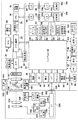
図1は、複数の撮影レンズを交換可能なカメラとその撮影レンズからなるカメラシステムであって焦点調節装置を有する撮像装置の構成を示す図である。図1において、本実施形態の焦点調節装置を含むカメラシステムはカメラ100とこれに交換可能に装着される撮影レンズ300とを備えて構成される。初めに、カメラ100の構成について説明する。
FIG. 1 is a diagram showing a configuration of an image pickup apparatus which is a camera system including a camera in which a plurality of photographing lenses can be exchanged and the photographing lenses and has a focus adjusting device. In FIG. 1, a camera system including the focus adjusting device of the present embodiment includes a
カメラ100は、複数種類の撮影レンズ300が存在するカメラシステムに対応しており、同一種類のレンズでも製造番号が異なるものが装着可能である。更には、焦点距離や開放F値が異なる撮影レンズ300若しくはズーム機能を備える撮影レンズ300なども装着可能で、同種、異種の撮影レンズにかかわらず交換可能な構成を有する。
The
このカメラ100において、撮影レンズ300を通過した光束は、カメラマウント106を通過し、メインミラー130により上方へ反射されて光学ファインダ104に入射する。光学ファインダ104により、撮影者は被写体を光学像として観察しながら撮影できる。光学ファインダ104内には、表示部54の一部の機能、例えば、合焦表示、手振れ警告表示、絞り値表示、露出補正表示等が設置されている。
In the
メインミラー130は半透過性のハーフミラーで構成され、メインミラー130に入射する光束のうち一部はこのハーフミラー部を通過しサブミラー131で下方へ反射されて焦点検出装置105へ入射する。焦点検出装置105は、2次結像光学系からなる位相差検出方式AF機構を採用しており、得られた光学像を電気信号に変換しAF部(オートフォーカス部)42へ送る。AF部42では、この電気信号から位相差検出演算を行う。この演算結果に基づき、システム制御回路50が、撮影レンズ300のフォーカス制御部342(後述する)に対して、焦点調節処理などの制御を行う。本実施形態では、焦点検出結果の補正もAF部42で行う。AF部42は、焦点検出手段として働く。
The
一方、撮影レンズ300の焦点調節処理が終了し静止画撮影、電子ファインダ表示、動画撮影を行う場合には、不図示のクイックリターン機構によりメインミラー130とサブミラー131を撮影光束外に退避させる。こうして、撮影レンズ300を通過した光束は、露光量を制御するためのシャッター12を介して、光学像を電気信号に変換する撮像素子14に入射する。これらの撮影動作終了後には、メインミラー130とサブミラー131は図示される様な位置に戻る。
On the other hand, when the focus adjustment process of the photographing
撮像素子14によって光電変換された電気信号はA/D変換器16へ送られ、アナログ信号出力がデジタル信号(画像データ)に変換される。タイミング発生回路18は、撮像素子14、A/D変換器16、D/A変換器26にクロック信号や制御信号を供給する。タイミング発生回路18は、メモリ制御回路22及びシステム制御回路50により制御される。画像処理回路20は、A/D変換器16からの画像データ或いはメモリ制御回路22からの画像データに対して所定の画素補間処理や色変換処理を行う。画像処理回路20は、画像データを用いて所定の演算処理を行う。
The electrical signal photoelectrically converted by the
撮像素子14は焦点検出装置の一部を有し、クイックリターン機構によりメインミラー130とサブミラー131が撮影光束外に退避した状態においても位相差検出方式AFを行うことができる。得られた画像データのうち、焦点検出に対応する画像データは、画像処理部20で焦点検出用画像データに変換される。その後、システム制御回路50を介してAF部42へ送られ、焦点調節装置により撮影レンズ300の焦点合わせが行われる。なお、画像処理回路20による撮像素子14の画像データを演算した演算結果に基づき、システム制御回路50が、撮影レンズ300のフォーカス制御部342に対して焦点合わせを行う所謂コントラスト方式AFも可能な構成となっている。こうして、電子ファインダ観察時や動画撮影時では、メインミラー130とサブミラー131が撮影光束外に退避するが、撮像素子14による位相差検出方式AFとコントラスト方式AFの両者が可能となっている。特に、位相差検出方式AFが可能であるため高速な焦点合わせが可能である。
The
この様に、本実施形態のカメラ100は、メインミラー130とサブミラー131が撮影光路内にある通常の静止画撮影では、焦点検出装置105による位相差検出方式AFを用いる。また、メインミラー130とサブミラー131が撮影光束外へ退避する電子ファインダ観察時や動画撮影時では、撮像素子14による位相差検出方式AFとコントラスト方式AFを用いる構成となっている。従って、静止画撮影、電子ファインダ、動画撮影のどの動作においても焦点調節が可能である。
As described above, the
メモリ制御回路22は、A/D変換器16、タイミング発生回路18、画像処理回路20、画像表示メモリ24、D/A変換器26、メモリ30、圧縮伸長回路32を制御する。そして、A/D変換器16のデータが画像処理回路20、メモリ制御回路22を介して、或いはA/D変換器16のデータが直接メモリ制御回路22を介して、画像表示メモリ24或いはメモリ30に書き込まれる。画像表示部28は液晶モニタ等から構成され、画像表示メモリ24に書き込まれた表示用の画像データを、D/A変換器26を介して画像表示部28により表示する。画像表示部28を用いて撮像した画像データを逐次表示することにより、電子ファインダ機能を実現できる。画像表示部28は、システム制御回路50の指示により表示をON/OFFすることが可能であり、表示をOFFにした場合にはカメラ100の電力消費を大幅に低減できる。
The
また、メモリ30は、撮影した静止画像や動画像を記憶するためのものであり、所定枚数の静止画像や所定時間の動画像を記憶するのに十分な記憶容量を備えている。これにより、連射撮影やパノラマ撮影の場合にも、高速かつ大量の画像書き込みをメモリ30に対して行うことができる。また、メモリ30はシステム制御回路50の作業領域としても使用できる。圧縮伸長回路32は、適応離散コサイン変換(ADCT)等により画像データを圧縮伸長する機能を有し、メモリ30に記憶された画像を読み込んで圧縮処理或いは伸長処理を行い、処理を終えた画像データをメモリ30に書き込む。
Further, the
シャッター制御部36は、測光部46からの測光情報に基づいて、撮影レンズ300側の絞り312を制御する絞り制御部344と連携しながら、シャッター12を制御する。インターフェース部38とコネクタ122は、カメラ100と撮影レンズ300とを電気的に接続する。これらは、カメラ100と撮影レンズ300との間で制御信号、状態信号、データ信号等を伝え合うと共に、各種電圧の電流を供給する機能も備えている。また、電気通信のみならず、光通信、音声通信等を伝達する構成としてもよい。測光部46は、AE処理を行う。撮影レンズ300を通過した光束を、カメラマウント106、ミラー130、そして不図示の測光用レンズを介して、測光部46に入射させることにより、画像の露出状態を測定できる。また、測光部46は、フラッシュ48と連携することで調光処理機能も有する。なお、画像処理回路20による撮像素子14の画像データを演算した演算結果に基づき、システム制御回路50が、シャッター制御部36と撮影レンズ300の絞り制御部344に対してAE制御を行うことも可能である。フラッシュ48は、AF補助光の投光機能、フラッシュ調光機能も有する。
The
システム制御回路50はカメラ100の全体を制御し、メモリ52はシステム制御回路50の動作用の定数、変数、プログラム等を記憶する。表示部54はシステム制御回路50でのプログラムの実行に応じて、文字、画像、音声等を用いて動作状態やメッセージ等を表示する液晶表示装置である。カメラ100の操作部近辺の視認し易い位置に単数或いは複数設置され、例えばLCDやLED等の組み合わせにより構成される。表示部54の表示内容のうち、LCD等に表示するものとしては、記録枚数や残撮影可能枚数等の撮影枚数に関する情報や、シャッタースピード、絞り値、露出補正、フラッシュ等の撮影条件に関する情報等がある。その他、電池残量や日付・時刻等も表示される。また、表示部54は、前述した様にその一部の機能が光学ファインダ104内に設置されている。
The
不揮発性メモリ56は、電気的に消去・記録可能なメモリであり、例えばEEPROM等が用いられる。60,62,64,66,68,70は、システム制御回路50に各種の動作指示を入力するための操作部であり、スイッチやダイアル、タッチパネル、視線検知によるポインティング、音声認識装置等の単数或いは複数の組み合わせで構成される。
The
モードダイアルスイッチ60は、電源オフ、オート撮影モード、マニュアル撮影モード、再生モード、PC接続モード等の各機能モードを切り替え設定できる。シャッタースイッチSW1(62)は、不図示のシャッターボタンが半押しされるとONとなり、AF処理、AE処理、AWB処理、EF処理等の動作開始を指示する。シャッタースイッチSW2(64)は、シャッターボタンが全押しされるとONとなり、撮影に関する一連の処理の動作開始を指示する。撮影に関する処理とは、露光処理、現像処理及び記録処理等のことである。露光処理では、撮像素子14から読み出した信号をA/D変換器16、メモリ制御回路22を介してメモリ30に画像データとして書き込む。現像処理では、画像処理回路20やメモリ制御回路22での演算を用いた現像を行う。記録処理では、メモリ30から画像データを読み出し、圧縮・伸長回路32で圧縮を行い、記録媒体150或いは160に画像データとして書き込む。
The
画像表示ON/OFFスイッチ66は、画像表示部28のON/OFFを設定できる。この機能により、光学ファインダ104を用いて撮影を行う際に、液晶モニタ等から成る画像表示部28への電流供給を遮断することにより、省電力を図ることができる。クイックレビューON/OFFスイッチ68は、撮影直後に撮影した画像データを自動再生するクイックレビュー機能のON/OFFを設定する。操作部70は、各種ボタンやタッチパネル等からなる。各種ボタンには、メニューボタン、フラッシュ設定ボタン、単写/連写/セルフタイマー切り替えボタン、露出補正ボタン等がある。
The image display ON / OFF switch 66 can set ON / OFF of the image display unit 28. With this function, when taking a picture using the optical finder 104, power saving can be achieved by cutting off the current supply to the image display unit 28 including the liquid crystal monitor and the like. The quick review ON / OFF switch 68 sets ON / OFF of the quick review function that automatically reproduces the image data captured immediately after shooting. The
電源制御部80は、電池検出回路、DC/DCコンバータ、通電するブロックを切り替えるスイッチ回路等により構成されている。電池の装着の有無、電池の種類、電池残量の検出を行い、検出結果及びシステム制御回路50の指示に基づいてDC/DCコンバータを制御し、必要な電圧を必要な期間、記録媒体を含む各部へ供給する。コネクタ82及び84は、アルカリ電池やリチウム電池等の一次電池、NiCd電池やNiMH電池やリチウムイオン電池等の二次電池、ACアダプタ等からなる電源部86をカメラ100と接続する。
The power
インターフェース90及び94は、メモリカードやハードディスク等の記録媒体との接続機能を有し、コネクタ92及び96は、メモリカードやハードディスク等の記録媒体と物理的接続を行う。記録媒体着脱検知部98は、コネクタ92または96に記録媒体が装着されているかどうかを検知する。なお、本実施形態では、記録媒体を取り付けるインターフェース及びコネクタを2系統持つものとして説明しているが、インターフェース及びコネクタは、単数或いは複数、いずれの系統数を備える構成としても構わない。また、異なる規格のインターフェース及びコネクタを組み合わせて備える構成としても構わない。更に、インターフェース及びコネクタにLANカード等の各種通信カードを接続することで、コンピュータやプリンタ等の他の周辺機器との間で画像データや画像データに付属した管理情報を転送し合うことができる。
The
通信部110は、有線通信、無線通信等の各種通信機能を有する。コネクタ112は、通信部110によりカメラ100を他の機器と接続し、無線通信の場合はアンテナである。記録媒体150及び160は、メモリカードやハードディスク等である。記録媒体150及び160は、半導体メモリや磁気ディスク等から構成される記録部152,162、カメラ100とのインターフェース154,164、カメラ100と接続を行うコネクタ156,166を備えている。
The
次に、撮影レンズ300について説明する。撮影レンズ300は、カメラ100に着脱可能に構成される。レンズマウント306は、撮影レンズ300をカメラ100と機械的に結合し、カメラマウント106を介してカメラ100に交換可能に取り付けられる。カメラマウント106及びレンズマウント306内には、撮影レンズ300をカメラ100と電気的に接続するコネクタ122及びコネクタ322の機能が含まれている。レンズ311には被写体の焦点合わせを行うフォーカスレンズが含まれ、絞り312は撮影光束の光量を制御する。
Next, the photographing
コネクタ322及びインターフェース338は、撮影レンズ300をカメラ100のコネクタ122と電気的に接続する。そして、コネクタ322は、カメラ100と撮影レンズ300との間で制御信号、状態信号、データ信号等を伝え合うと共に、各種電圧の電流を供給される機能も備えている。コネクタ322は電気通信のみならず、光通信、音声通信等を伝達する構成としてもよい。ズーム制御部340はレンズ311のズーミングを制御し、フォーカス制御部342はレンズ311のフォーカスレンズの動作を制御する。フォーカス制御部342とレンズ311は、焦点調節手段を構成している。撮影レンズ300がズーム機能のない単焦点レンズタイプであればズーム制御部340はなくてもよい。絞り制御部344は、測光部46からの測光情報に基づいて、シャッター12を制御するシャッター制御部36と連携しながら、絞り312を制御する。絞り制御部344と絞り312は、絞り開口調節手段を構成している。
The
レンズシステム制御回路346は撮影レンズ300全体を制御する。そして、レンズシステム制御回路346は、撮影レンズの動作用の定数、変数、プログラム等を記憶するメモリの機能を備えている。不揮発性メモリ348は、撮影レンズ固有の番号等の識別情報、管理情報、開放絞り値や最小絞り値、焦点距離等の機能情報、現在や過去の各設定値などを記憶する。本実施形態においては、撮影レンズ300の状態に応じたレンズ枠情報も記憶されている。このレンズ枠情報は、撮影レンズ300を通過する光束を決定する枠開口の撮像素子14からの距離と枠開口の半径の情報である。絞り312は、撮影レンズを通過する光束を決定する枠に含まれ、他にもレンズを保持するレンズ枠部品の開口などが枠に該当する。また、撮影レンズを通過する光束を決定する枠は、レンズ311のフォーカス位置やズーム位置によって異なるため、レンズ311のフォーカス位置やズーム位置に対応して複数用意されている。そして、カメラ100が、焦点検出手段を用いて焦点検出を行う際には、レンズ311のフォーカス位置とズーム位置に対応した最適なレンズ枠情報が選択され、カメラ100にコネクタ322を通じて送られる構成となっている。
The lens
以上が、カメラ100と撮影レンズ300からなるカメラシステムの構成である。次に、撮像素子14からなる焦点検出装置について詳細を説明する。この焦点検出装置は焦点検出装置105と同様に位相差検出方式AFを採用している。その構成について説明する。
The above is the configuration of the camera system including the
図1に示す撮像素子14の構成を図2A〜2Cを用いてより詳細に説明する。図2Aは、撮像素子14内の画素200の構成を示す回路図である。1つの画素200は、2つのフォトダイオード(PD)201a,201b、2つの転送スイッチ202a,202b、フローティングディフュージョン領域203、増幅部204、リセットスイッチ205、選択スイッチ206を有する。なお、各スイッチはMOSトランジスタ等により構成され得る。以下の説明では各スイッチは一例としてN型のMOSトランジスタであるものとするが、各スイッチはP型のMOSトランジスタであってもよく、その他のスイッチング素子であってもよい。
The configuration of the
このように、本実施形態における撮像素子14は、1つの画素200内に、2つのフォトダイオードを有する。ただし、各画素200に設けられるフォトダイオードの個数は図2Aに示される2つに限定されず、3つ以上(例えば、4つ)設けられてもよい。本実施形態においてフォトダイオード201a,201bは、後述するように、焦点検出画素として機能するとともに、撮像画素としても機能する。
As described above, the
フォトダイオード201a,201bは、図2Bに示す同一のマイクロレンズ236を通過した光を受光し、光電変換によりその受光量に応じた信号電荷を生成する光電変換部として機能する。フォトダイオード201aにより得られる信号をA信号、フォトダイオード201bにより得られる信号をB信号と呼ぶ。
The
転送スイッチ202aはフォトダイオード201aとフローティングディフュージョン領域203との間に接続され、転送スイッチ202bはフォトダイオード201bとフローティングディフュージョン領域203との間に接続される。転送スイッチ202a,202bは、それぞれフォトダイオード201a,201bで発生した電荷を共通のフローティングディフュージョン領域203に転送する素子である。転送スイッチ202a,202bは、それぞれ制御信号TX_A、TX_Bによって制御される。
The
フローティングディフュージョン領域203は、フォトダイオード201a,201bから転送された電荷を一時的に保持するとともに、保持した電荷を電圧信号に変換する電荷電圧変換部として機能する。
The floating
増幅部204は、ソースフォロワMOSトランジスタである。増幅部204のゲートは、フローティングディフュージョン領域203に接続され、増幅部204のドレインは電源電位VDDを供給する共通電源208に接続される。増幅部204は、フローティングディフュージョン領域203に保持された電荷に基づく電圧信号を増幅して、画像信号として出力する。
The
リセットスイッチ205は、フローティングディフュージョン領域203と共通電源208との間に接続される。リセットスイッチ205は、制御信号RESによって制御され、フローティングディフュージョン領域203の電位を電源電位VDDにリセットする機能を有する。
The
選択スイッチ206は、増幅部204のソースと垂直出力線207の間に接続される。選択スイッチ206は、制御信号SELによって制御され、増幅部204で増幅された画像信号を垂直出力線207に出力する。
The
図2Cは、撮像素子14の構成を示す図である。撮像素子14は、画素アレイ234、垂直走査回路209、電流源負荷210、読み出し回路235、共通出力線228,229、水平走査回路232、データ出力部233を有する。
FIG. 2C is a diagram showing the configuration of the
画素アレイ234は、行列状に配置された複数の画素200を有する。図2Cには説明を簡略化するために、水平方向にn画素、垂直方向に4画素を示しているが、画素200の行数及び列数は任意である。また、各画素200には複数色のカラーフィルタのうちいずれか1つが設けられている。図2Cに示す例では、カラーフィルタの色は赤色(R)、緑色(G)、青色(B)とする。これらの各画素200はベイヤー配列に従って配置される。また、本実施形態における撮像素子14は画素アレイ234の一部が遮光層で遮光された領域(OB)を持つ。
The
垂直走査回路209は、行ごとに設けられた駆動信号線208を介して、各行の画素200に制御信号を出力する。なお、図2Cでは、駆動信号線208は、簡略化のため行ごとに1本ずつ図示されているが、実際には行ごとに複数の駆動信号線が接続される。
The
同じ列の画素200は列ごとに設けられた垂直出力線207に共通接続される。各画素200から出力される信号は、この垂直出力線207を介して読み出し回路235に入力され、読み出し回路235で処理される。電流源負荷210は各列の垂直出力線207に接続される。
水平走査回路232は、制御信号hsr(0)〜hsr(n−1)を出力することにより、複数の読み出し回路235の中から信号を出力させる列を順次選択する。選択された列の読み出し回路235は、共通出力線228,229を介してデータ出力部233に処理した信号を出力する。
By outputting the control signals hsr (0) to hsr (n-1), the
次に、読み出し回路235の具体的な回路構成について説明する。読み出し回路235は、クランプ容量211、フィードバック容量214〜216、オペアンプ213、基準電圧源212、スイッチ217〜220を有する。また、比較器221、Latch_N222、Latch_S223、スイッチ226,227を有する。
Next, a specific circuit configuration of the read
垂直出力線207により読み出し回路235に入力される信号はクランプ容量211を介してオペアンプ213の反転入力端子に入力される。オペアンプ213の非反転入力端子には、基準電圧源212から基準電圧Vrefが供給される。フィードバック容量214〜216はオペアンプ213の反転入力端子と出力端子の間に接続される。スイッチ217もオペアンプ213の反転入力端子と出力端子の間に接続され、フィードバック容量214〜216の両端をショートさせる機能を有する。スイッチ217は制御信号RES_Cにより制御される。また、スイッチ218〜220は制御信号GAIN0〜2で制御される。
The signal input to the
比較器221にはオペアンプ213の出力信号と、ランプ信号発生器230から出力されるランプ信号224が入力される。Latch_N222はノイズレベル(N信号)を保持するための記憶素子であり、Latch_SはA信号およびA信号とB信号が加算されたAB信号の信号レベル(S信号)を保持するための記憶素子である。Latch_N222とLatch_S223は、それぞれ制御信号LATEN_N,LATEN_Sで制御され、比較器221の出力信号と、カウンタ231から出力されるカウンタ値225とが入力される。Latch_N222とLatch_S223の出力端子はスイッチ226,227を介してそれぞれ共通出力線228,229に接続される。共通出力線228,229はデータ出力部233に接続される。
The output signal of the
スイッチ226,227は水平走査回路232からの制御信号hsr(h)信号で制御される。ここで、hは制御信号線が接続されている読み出し回路235の列番号を示す。Latch_N222とLatch_S223に保持された信号は、共通出力線238,229、データ出力部233を介して外部へ出力される。この動作を水平転送と呼ぶ。
The
なお、本実施形態の撮像素子は以下の2種類の読み出しモードを有する。第1の読み出しモードは全画素読み出しモードと称するもので、高精細静止画を撮像するためのモードである。この場合は、全画素の信号が読み出される。 The image sensor of this embodiment has the following two types of readout modes. The first readout mode is called an all-pixel readout mode, which is a mode for capturing a high-definition still image. In this case, the signals of all pixels are read out.
第2の読み出しモードは間引き読み出しモードと称するもので、動画記録、もしくはプレビュー画像の表示のみを行なうためのモードである。この場合に必要な画素数は全画素数よりも少ないため、画素群はX方向及びY方向ともに所定比率に間引いた画素のみ読み出される。また、高速に読み出す必要がある場合にも、同様に間引き読み出しモードを用いる。X方向に間引く際には、信号の加算を行いS/Nの改善を図り、Y方向に対する間引きは、間引かれる行の信号出力を無視する。 The second read mode is called a thinning read mode, which is a mode for recording a moving image or displaying only a preview image. Since the number of pixels required in this case is smaller than the total number of pixels, only the pixels thinned out to a predetermined ratio in both the X direction and the Y direction are read out. Also, when it is necessary to read at high speed, the thinning read mode is also used. When thinning out in the X direction, signals are added to improve S / N, and when thinning out in the Y direction, the signal output of the line to be thinned out is ignored.
図3A、図3Bは、本実施形態の撮像装置において、撮影光学系の射出瞳面と、像高ゼロすなわち像面中央近傍に配置された撮像素子の光電変換部の共役関係を説明する図である。撮像素子内の光電変換部と撮影光学系の射出瞳面は、オンチップマイクロレンズによって共役関係となるように設計される。そして撮影光学系の射出瞳は、一般的に光量調節用の虹彩絞りが置かれる面とほぼ一致する。一方、本実施形態の撮影光学系は変倍機能を有したズームレンズであるが、光学タイプによっては変倍操作を行なうと、射出瞳の像面からの距離や大きさが変化する。図3Aにおける撮影光学系は、焦点距離が広角端と望遠端の中間、すなわちMiddleの状態を示している。これを標準的な射出瞳距離Zepと仮定して、オンチップマイクロレンズの形状や、像高(X、Y座標)に応じた偏心パラメータの最適設計がなされる。 3A and 3B are diagrams for explaining the conjugate relationship between the exit pupil surface of the photographing optical system and the photoelectric conversion unit of the image pickup device arranged at zero image height, that is, near the center of the image surface in the image pickup apparatus of the present embodiment. be. The photoelectric conversion unit in the image sensor and the exit pupil surface of the photographing optical system are designed to have a conjugated relationship by an on-chip microlens. The exit pupil of the photographing optical system generally coincides with the surface on which the iris diaphragm for adjusting the amount of light is placed. On the other hand, the photographing optical system of the present embodiment is a zoom lens having a scaling function, but depending on the optical type, the distance and size of the exit pupil from the image plane change when the scaling operation is performed. The photographing optical system in FIG. 3A shows a state in which the focal length is between the wide-angle end and the telephoto end, that is, Middle. Assuming this is the standard exit pupil distance Zep, the optimum design of the eccentricity parameter according to the shape of the on-chip microlens and the image height (X, Y coordinates) is made.
図3Aにおいて、101はレンズ311を構成する第1レンズ群、101bは第1レンズ群を保持する鏡筒部材、105はレンズ311を構成する第3レンズ群、105bは第3レンズ群を保持する鏡筒部材である。312は絞りで、312aは絞り開放時の開口径を規定する開口板、312bは絞り込み時の開口径を調節するための絞り羽根である。なお、撮影光学系を通過する光束の制限部材として作用する101b,312a,312b,105bは、像面から観察した場合の光学的な虚像を示している。また、絞り312の近傍における合成開口をレンズの射出瞳と定義し、前述したように像面からの距離をZepとしている。
In FIG. 3A, 101 is a first lens group constituting the
被写体像を光電変換するための画素2110は、像面中央近傍に配置されており、本実施形態では、中央画素と呼ぶ。中央画素2110は、最下層より、光電変換部201a,201b、配線層2110e〜2110g、カラーフィルタ2110h、オンチップマイクロレンズ236の各部材で構成される。そして2つの光電変換部はオンチップマイクロレンズ236によって撮影光学系の射出瞳面に投影される。また別の言い方をすれば、撮影光学系の射出瞳が、オンチップマイクロレンズ236を介して、光電変換部の表面に投影されることになる。
図3Bは、撮影光学系の射出瞳面上における、光電変換部の投影像を示した図で、光電変換部201a及び201bに対する投影像は各々EP1a及びEP1bとなる。また本実施形態では、撮像素子は、2つの光電変換部201aと201bのいずれか一方の出力と、両方の和の出力を得ることができる画素を有している。両方の和の出力は、撮影光学系のほぼ全瞳領域である投影像EP1a,EP1bの両方の領域を通過した光束を光電変換したものである。投影像EP1aを第1の瞳領域と呼び、投影像EP1bを第2の瞳領域と呼ぶ。
FIG. 3B is a diagram showing projected images of the photoelectric conversion unit on the exit pupil surface of the photographing optical system, and the projected images on the
図3Aで、撮影光学系を通過する光束の最外部をLで示すと、光束Lは、絞りの開口板312aで規制されており、投影像EP1a及びEP1bは撮影光学系でケラレがほぼ発生していない。図3Bでは、図3Aの光束Lを、TLで示している。TLで示す円の内部に、光電変換部の投影像EP1a,EP1bの大部分が含まれていることからも、ケラレがほぼ発生していないことがわかる。光束Lは、絞りの開口板312aでのみ制限されているため、TLは、312aと言い換えることができる。この際、像面中央では各投影像EP1a,EP1bのけられ状態は光軸に対して対称となり、各光電変換部201a及び201bが受光する光量は等しい。
In FIG. 3A, when the outermost light flux passing through the photographing optical system is indicated by L, the luminous flux L is regulated by the
以上図2A〜図3Bを用いて説明した様に、撮像素子14は撮像のみの機能だけではなく焦点検出装置としての機能も有している。また、焦点検出方法としては、射出瞳を分割した光束を受光する焦点検出用画素を備えているため、位相差検出方式AFを行うことが可能である。
As described above with reference to FIGS. 2A to 3B, the
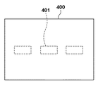
図4は、撮影範囲400内における焦点検出領域401を示す図で、この3つの焦点検出領域内で撮像素子14による位相差検出方式AFが行われる。焦点検出領域401内では、撮影範囲400内の水平方向のコントラスト差を用いて位相差検出を行う。
FIG. 4 is a diagram showing a
なお本実施形態では、撮像素子14の1画素が、複数の光電変換部を持つように説明したが、焦点検出画素の実現方法はこれに限定されるものではない。例えば、撮像素子14の画素が、互いに異なる一部を遮光された光電変換部を持ち、焦点検出専用の画素として配置されるように構成してもよい。
In the present embodiment, it has been described that one pixel of the
図5は、本実施形態における一対の焦点検出信号の例を示す図である。一対の焦点検出信号430a,430bは、撮像素子14から得られた画素信号(A信号、B信号)に対して、画像処理回路20よる各種の画像処理(補正)が施された信号である。一対の焦点検出信号430a,430bは、AF部42へ送られる。
FIG. 5 is a diagram showing an example of a pair of focus detection signals in the present embodiment. The pair of
図5において、横軸は連結された信号の画素配列方向、縦軸は信号の強度をそれぞれ示す。ここでは、撮影レンズ300の焦点が撮像素子14に対してデフォーカスした状態(非合焦状態)である。このため、焦点検出信号430aは左側にずれ、焦点検出信号430bは右側にずれている。AF部42は、焦点検出信号430a,430bのずれ量(相対ずれ量)を周知の相関演算などを用いて算出する。これにより、撮影光学系のピント状態を示すデフォーカス量を求めることができる。
In FIG. 5, the horizontal axis represents the pixel arrangement direction of the connected signals, and the vertical axis represents the signal strength. Here, the focus of the photographing
システム制御回路50は、レンズシステム制御回路346から送信されたレンズ311内のフォーカスレンズの位置情報およびAF部42から得られるデフォーカス量に基づいて、フォーカスレンズの駆動量を算出する。その後、システム制御回路50は、レンズ311内のフォーカスレンズの位置情報に基づいて、レンズシステム制御回路346及びフォーカス制御部342に対して、フォーカスレンズを駆動するべき位置情報を送信する。これにより、焦点調節を行うことが可能となる。
The
次に、図6は、本実施形態におけるカメラ100の動作を示すフローチャートであり、カメラ100のライブビュー状態で撮影を行う際のメインフローを示している。図6の各ステップは、主にシステム制御回路50の指令に基づいて実行される。
Next, FIG. 6 is a flowchart showing the operation of the
図6においてライブビュー撮影が開始されると、まずステップS1において、システム制御回路50は、撮像素子14の撮像動作を開始して、撮像データ(画素信号)を取得する。続いてステップS2において、システム制御回路50は、ステップS1において得られた撮像データから、画像データ(画像信号)および焦点検出データ(焦点検出信号)を取得する。前述のように、本実施形態の撮像素子14は、1つの画素から、画像信号のデータに加えて、焦点検出信号のデータを取得可能である。
When the live view shooting is started in FIG. 6, first, in step S1, the
続いてステップS3において、システム制御回路50は、ステップS2において得られた画像データに基づいて、プレビュー画像を画像表示部28に表示する、所謂ライブビュー表示を行う。撮影者は、このプレビュー画像を目視して撮影時の構図を決定する。ここで行うライブビュー表示は、撮影者が撮影範囲や撮影条件の確認を行うために行われ、所定の時間間隔で更新される。例えば、33.3ms(30fps)や16.6ms(60fps)の時間間隔で更新される。
Subsequently, in step S3, the
続いてステップS4において、システム制御回路50(AF部42)は、図4に示される3つの焦点検出領域における焦点検出データを用いて焦点検出処理を行う。すなわちAF部42は、図5に示されるような焦点検出信号のずれ量に基づいて、デフォーカス量を算出するまでの処理を焦点検出処理として行う。
Subsequently, in step S4, the system control circuit 50 (AF unit 42) performs the focus detection process using the focus detection data in the three focus detection regions shown in FIG. That is, the
続いてステップS5において、システム制御回路50は、撮影準備開始を示すスイッチSW1のオン/オフを検出する。操作部70の一つであるシャッタースイッチ(撮影トリガスイッチ)は、そのスイッチの押し込み量に応じて、2段階のオン/オフを検出することが可能である。スイッチSW1は、シャッタースイッチの1段階目のオンで検出可能に構成されている。ステップS5においてスイッチSW1のオンが検出されない場合、ステップS10に進む。ステップS10において、システム制御回路50は、メインスイッチがオフされたか否かを判定する。メインスイッチがオフされていない場合、ステップS2に戻る。一方、メインスイッチがオフされた場合、本フローを終了する。
Subsequently, in step S5, the
一方、ステップS5においてスイッチSW1のオンが検出されると、ステップS6に進む。ステップS6において、システム制御回路50は、焦点検出領域を設定する。焦点検出領域は、撮影者が指示する焦点検出領域に設定することができる。または、ステップS4において得られた3つの焦点検出領域のデフォーカス量の情報や焦点検出領域の撮影範囲中心からの距離の情報を用いて、システム制御回路50が焦点検出領域を自動的に設定するように構成してもよい。一般に、撮影者が意図する被写体は、より撮影距離の短い位置に存在する確率が高く、撮影範囲内の中央に存在する確率が高い。このため、システム制御回路50が焦点検出領域を設定する場合、そのような焦点検出領域が優先的に選択されることが好ましい。
On the other hand, when the on of the switch SW1 is detected in step S5, the process proceeds to step S6. In step S6, the
次にステップS7において、システム制御回路50(AF部42)は、焦点調節処理を行う。ステップS7の焦点調節処理の詳細については後述する。ステップS7の焦点調節処理が終了すると、ステップS8に進む。 Next, in step S7, the system control circuit 50 (AF unit 42) performs the focus adjustment process. The details of the focus adjustment process in step S7 will be described later. When the focus adjustment process in step S7 is completed, the process proceeds to step S8.
ステップS8において、システム制御回路50は、撮影開始指示を示すスイッチSW2のオン/オフを検出する。操作部70の一つであるシャッタースイッチは、そのスイッチの押し込み量に応じて、2段階のオン/オフを検出することが可能である。スイッチSW2は、シャッタースイッチの2段階目のオンで検出可能に構成されている。ステップS8においてスイッチSW2のオンが検出されない場合、スイッチSW2のオンが検出されるまでステップS8において撮影待機状態を維持する。一方、ステップS8においてスイッチSW2のオンが検出されると、ステップS9に進む。ステップS9において、システム制御回路50は、撮影サブルーチンを実行する。ステップS9の撮影サブルーチンの詳細については後述する。
In step S8, the
ステップS9において撮影サブルーチンが終了すると、ステップS10に進む。ステップS10において、システム制御回路50は、メインスイッチがオフされたか否かを判定する。メインスイッチがオフされていない場合、ステップS2に戻る。一方、メインスイッチがオフされた場合、本フローの一連の動作を終了する。
When the shooting subroutine is completed in step S9, the process proceeds to step S10. In step S10, the
次に、図7を参照して、図6のステップS7の焦点調節処理について説明する。図7は、焦点調節処理を示すフローチャートである。図7の各ステップは、主にシステム制御回路50の指令に基づいて実行される。
Next, with reference to FIG. 7, the focus adjustment process of step S7 of FIG. 6 will be described. FIG. 7 is a flowchart showing the focus adjustment process. Each step of FIG. 7 is mainly executed based on a command of the
焦点調節処理が開始されると、ステップS201において、システム制御回路50は、事前に行われた焦点検出結果の取得を行う。図6のステップS4及びS6で設定された焦点検出領域のデフォーカス量を取得する。また、得られたデフォーカス量の信頼性が高いか否かも同時に判定する。信頼性の判定は、信頼性判定手段としてのシステム制御回路50が行う。具体的には、信頼性の判定として、周知の相関量の極小値の大きさと極小値近傍の相関量の差分の大きさを用いた判定などを行う。
When the focus adjustment process is started, in step S201, the
相関量とは、1対の焦点検出信号の領域ごとの相関度合いを示すもので、相関が高いほど小さい値を示す。そのため、相関量CORの極小値の大きさについては、極小値が小さければ小さいほど信頼性が高いと判定する。理想的には、相関量CORの極小値は、1対の焦点検出信号が完全に同一形状である場合に0となる。しかしながら、1対の焦点検出信号は、被写体からの光の拡散特性や光量調整誤差や画素ごとに個別に生じるノイズの影響などにより、形状が異なる。そのため、相関量CORの極小値は、正の値となるのが一般的である。一方で、1対の焦点検出信号の形状が異なれば異なるほど、極小値の検出精度が悪化し、結果的に焦点検出精度が悪化する。ここで行う信頼性判定では、1つの方法として、閾値Thr1よりも相関量CORの極小値が小さければ、信頼性が高いと判定する。 The amount of correlation indicates the degree of correlation for each region of a pair of focus detection signals, and the higher the correlation, the smaller the value. Therefore, regarding the magnitude of the minimum value of the correlation amount COR, it is determined that the smaller the minimum value, the higher the reliability. Ideally, the minimum value of the correlation amount COR is 0 when the pair of focus detection signals have exactly the same shape. However, the pair of focus detection signals have different shapes due to the diffusion characteristics of light from the subject, the light amount adjustment error, the influence of noise generated individually for each pixel, and the like. Therefore, the minimum value of the correlation amount COR is generally a positive value. On the other hand, the different the shapes of the pair of focus detection signals, the worse the detection accuracy of the minimum value, and as a result, the worse the focus detection accuracy. In the reliability determination performed here, as one method, if the minimum value of the correlation amount COR is smaller than the threshold value Thr1, it is determined that the reliability is high.
また、相関量が極小値を示す領域近傍で得られた相関量の差分DCORを用いた信頼性判定を行う。相関量の差分DCORは、大きければ大きいほど、シフト量を高精度に算出することができる。これは、相関量が誤差によりばらついた場合でも、相関量の差分が大きければ、シフト量の検出に与える影響が小さいためである。このことから、閾値Thr2より相関量の差分DCORが大きい場合に、信頼性が高いと判定することができる。 Further, the reliability is determined using the difference DCOR of the correlation amount obtained in the vicinity of the region where the correlation amount shows the minimum value. The larger the difference DCOR of the correlation amount, the more accurately the shift amount can be calculated. This is because even if the correlation amount varies due to an error, if the difference in the correlation amount is large, the influence on the detection of the shift amount is small. From this, it can be determined that the reliability is high when the difference DCOR of the correlation amount is larger than the threshold value Thr2.
次に、ステップS202において、信頼性の高いデフォーカス量が検出できているか否かを判定する。信頼性の高いデフォーカス量が検出できている場合には、ステップS203に進み、検出されたデフォーカス量が所定の閾値以下で、合焦状態にあるか否かを判定する。合焦状態ではないと判定された場合、ステップS203でNoとなり、ステップS204に進み、検出されたデフォーカス量に基づくフォーカスレンズの駆動を行う。 Next, in step S202, it is determined whether or not a highly reliable defocus amount can be detected. If a highly reliable defocus amount can be detected, the process proceeds to step S203, and it is determined whether or not the detected defocus amount is equal to or less than a predetermined threshold value and is in the in-focus state. If it is determined that the focus is not in focus, the result is No in step S203, the process proceeds to step S204, and the focus lens is driven based on the detected defocus amount.
ステップS203で、検出されたデフォーカス量が所定の閾値以下で、合焦状態にあると判定された場合(S203でYes)には、ステップS205に進み、画像表示部28に、合焦表示を行う。例えば、焦点検出領域と対応した枠を、緑の色で表示したり、音を出力したりする。 If it is determined in step S203 that the detected defocus amount is equal to or less than a predetermined threshold value and the subject is in focus (Yes in S203), the process proceeds to step S205, and the image display unit 28 displays the focus. conduct. For example, the frame corresponding to the focus detection area is displayed in green color or sound is output.
一方で、ステップS202で、信頼性の高いデフォーカス量が検出できていない場合、ステップS206に進み、絞り状態変更要否判定手段であるシステム制御回路50は、絞り込み要否判定を行う。本実施形態では、開放絞り状態(第1の絞り開口状態)で信頼性の高いデフォーカス量が検出できない場合に、絞り込みを行い第2の絞り開口状態へ移行する。これにより、検出可能なデフォーカス範囲を拡大し、誤った方向へのレンズ駆動の頻度を低減し、高速な焦点調節を実現する。但し、絞り込みを行い第2の絞り開口状態でもなお、焦点検出が不可能な場合には、絞り込みに要した時間分、焦点調節の応答性を損ねる。ステップS202では、不要な絞込みの頻度を低減するために、絞り込みの要否を判定する。詳細は後述する。
On the other hand, if a highly reliable defocus amount cannot be detected in step S202, the process proceeds to step S206, and the
絞り込みの要否判定を終えると、ステップS207に進み、絞り込み量の算出を行う。上述の通り絞込みには一定の時間が必要となるため、必要最低限の絞り込み量を検出し、駆動を行うことで、絞り込みによる焦点調節の応答性低下を最低限にすることができる。本実施形態では、ステップS207で最適な絞込み量の算出を行う。ステップS206で絞込み不要と判定されている場合に、ステップS207はスキップしても構わない。 When the determination of necessity of narrowing down is completed, the process proceeds to step S207 to calculate the narrowing down amount. As described above, since a certain amount of time is required for narrowing down, it is possible to minimize the decrease in responsiveness of focus adjustment due to narrowing down by detecting and driving the minimum necessary narrowing down amount. In the present embodiment, the optimum narrowing amount is calculated in step S207. If it is determined in step S206 that narrowing down is unnecessary, step S207 may be skipped.
次に、ステップS208において、ステップS206での判定結果に基づいて、絞りを絞るか否かの判定を行う。絞りを絞り込む場合(S208でYes)、ステップS209に進み、ステップS207で算出された絞り込み量に基づき、絞りを駆動する。その後、ステップS210に進み、焦点検出処理を行う。ここで行う処理は、図6のステップS4で行われる処理と同様である。また、焦点検出の信頼性も同時に判定する。 Next, in step S208, it is determined whether or not to stop down the aperture based on the determination result in step S206. When narrowing down the aperture (Yes in S208), the process proceeds to step S209, and the aperture is driven based on the aperture amount calculated in step S207. After that, the process proceeds to step S210 to perform the focus detection process. The process performed here is the same as the process performed in step S4 of FIG. At the same time, the reliability of focus detection is also determined.
ステップS210の焦点検出処理を終えると、ステップS211に進み、信頼性の高いデフォーカス量が得られたか否かを判定する。信頼性の高いデフォーカス量が得られた場合(S211でYes)には、ステップS212に進み絞り開放判定を行う。絞り込み時(第2の絞り開口状態)には、絞り開放時(第1の絞り開口状態)に比べて、検出可能なデフォーカス量が大きいため、より速くフォーカスレンズを駆動しても合焦位置を通り過ぎる懸念が少ない。ステップS212では、検出されるデフォーカス量が、所定の閾値以下になるまでは、絞り込みを行った状態(第2の絞り開口状態)でレンズ駆動を行うため、絞りを開放状態にするべきか否かの判定を行う。 When the focus detection process in step S210 is completed, the process proceeds to step S211 to determine whether or not a highly reliable defocus amount has been obtained. When a highly reliable defocus amount is obtained (Yes in S211), the process proceeds to step S212 to determine the aperture opening. When the aperture is stopped down (second aperture opening state), the amount of defocus that can be detected is larger than when the aperture is opened (first aperture opening state), so even if the focus lens is driven faster, the in-focus position There is little concern about passing through. In step S212, until the detected defocus amount becomes equal to or less than a predetermined threshold value, the lens is driven in the state where the aperture is stopped down (the second aperture opening state), so whether or not the aperture should be opened. Is determined.
ステップS213では、ステップS212の判定結果に基づいて、絞りを開くか否かを判定する。絞りを開く場合には、ステップS214に進み、絞りを開放状態(第1の絞り開口状態)に駆動する。その後、ステップS215に進み、図6のステップS4と同様に焦点検出処理を行う。ステップS215で焦点検出処理を終えると、ステップS203以降の処理を、上述した場合と同様に行う。 In step S213, it is determined whether or not to open the aperture based on the determination result in step S212. When opening the aperture, the process proceeds to step S214, and the aperture is driven to the open state (first aperture opening state). After that, the process proceeds to step S215, and the focus detection process is performed in the same manner as in step S4 of FIG. When the focus detection process is completed in step S215, the processes after step S203 are performed in the same manner as described above.
一方で、ステップS213で絞りを開かないと判定された場合には、ステップS216に進み、ステップS210で検出されたデフォーカス量に基づき、フォーカスレンズの駆動を行う。ステップS216を終えると、ステップS210に戻り、引き続き第2の絞り開口状態での焦点検出処理を行う。 On the other hand, if it is determined in step S213 that the aperture is not opened, the process proceeds to step S216, and the focus lens is driven based on the defocus amount detected in step S210. When step S216 is completed, the process returns to step S210, and the focus detection process in the second aperture opening state is continuously performed.
ステップS210で信頼性の高いデフォーカス量が得られなかった場合には、ステップS211でNoとなり、ステップS217に進む。ステップS217では、非合焦と判定する前に、サーチ駆動が必要か否かを判定する。本実施形態では、第1の絞り開口状態と第2の絞り開口状態の両方で、焦点検出を行っている。焦点検出時に得られる信号や評価値から、サーチ駆動を行っても合焦状態に移行できる可能性が少ないと判定できる場合がある。例えば、絞り込み前後で焦点検出信号の明暗差(コントラスト)が変わらない場合などは、サーチ駆動を行っても合焦状態に移行できる可能性が低く、サーチ駆動を行う必要はないと判定できる。もしくは、被写体信号の所定の周波数成分の変化などを検出して、変化が少ない場合に、サーチ駆動は不要と判定してもよい。このような判定が可能になるのは、絞りの変化は、主に被写体光束の焦点深度にのみ影響を与えるためである。絞り込むことにより被写体光束の焦点深度が深くなり、焦点検出信号の明暗差が大きくなったり、所定の周波数成分の信号量が増えたりすることにより、検出可能なデフォーカス量が拡大する。反対に、焦点検出信号の明暗差や信号量に変化が少ない場合には、そもそもコントラストの高い被写体のパターン(模様)が焦点検出領域内に存在しないことが推定される。このことを利用して、ステップS217では、サーチの要否判定を行う。 If a highly reliable defocus amount cannot be obtained in step S210, the result becomes No in step S211 and the process proceeds to step S217. In step S217, it is determined whether or not search driving is necessary before determining that the subject is out of focus. In the present embodiment, focus detection is performed in both the first aperture opening state and the second aperture opening state. From the signal and the evaluation value obtained at the time of focus detection, it may be determined that there is little possibility that the focus state can be achieved even if the search drive is performed. For example, when the difference in brightness (contrast) of the focus detection signal does not change before and after narrowing down, it is unlikely that the focus detection signal can be shifted to the in-focus state even if the search drive is performed, and it can be determined that the search drive is not necessary. Alternatively, it may be determined that the search drive is unnecessary when a change in a predetermined frequency component of the subject signal is detected and the change is small. Such a determination is possible because the change in the aperture mainly affects only the depth of focus of the subject luminous flux. By narrowing down, the depth of focus of the subject luminous flux becomes deeper, the difference in brightness of the focus detection signal increases, and the amount of signals of a predetermined frequency component increases, so that the amount of defocus that can be detected increases. On the contrary, when there is little change in the brightness difference or the signal amount of the focus detection signal, it is presumed that the pattern of the subject having high contrast does not exist in the focus detection region in the first place. Utilizing this fact, in step S217, the necessity of the search is determined.
ステップS217で、サーチ不要と判定されると、ステップS220に進み、画像表示部28に非合焦表示を行う。例えば、焦点検出領域と対応した枠を、赤の色で表示したり、合焦表示時とは異なる音を出力したりする。 If it is determined in step S217 that the search is unnecessary, the process proceeds to step S220 to display the out-of-focus display on the image display unit 28. For example, the frame corresponding to the focus detection area is displayed in red, or a sound different from that in the in-focus display is output.
一方で、ステップS217でサーチが必要と判定された場合には、ステップS218に進み、サーチ駆動を開始し、レンズ駆動を行いながら、焦点検出処理を行う。ここで行う焦点検出処理も図6のステップS4で行った処理と同様である。ステップS218で焦点検出を終えると、ステップS219でフォーカスレンズがレンズ駆動範囲の端部に到達しているか否かを判定する。フォーカスレンズがレンズ駆動範囲の端部に到達していない場合には、ステップS210に戻り焦点検出処理とサーチ駆動を継続する。ステップS219でフォーカスレンズがレンズ駆動範囲の端部に到達している場合は、合焦可能な被写体は、レンズ駆動範囲内に存在しないと判定し、ステップS220に進み、非合焦表示を行う。ステップS219では、レンズ駆動範囲の端部の両端を検出した際にステップS220に進んでもよいし、例えば、至近側の被写体の合焦可能な端部一方のみを検出した場合に、ステップS220に進んでもよい。一方の端部のみを検出するか、両方の端部を検出するかは、後述する検出可能なデフォーカス量を用いたレンズ端判定結果により切り替えてもよい。 On the other hand, if it is determined in step S217 that a search is necessary, the process proceeds to step S218, the search drive is started, and the focus detection process is performed while driving the lens. The focus detection process performed here is the same as the process performed in step S4 of FIG. When the focus detection is completed in step S218, it is determined in step S219 whether or not the focus lens has reached the end of the lens driving range. If the focus lens has not reached the end of the lens drive range, the process returns to step S210 to continue the focus detection process and the search drive. When the focus lens reaches the end of the lens driving range in step S219, it is determined that the subject capable of focusing does not exist within the lens driving range, and the process proceeds to step S220 to display the out-of-focus display. In step S219, the process may proceed to step S220 when both ends of the end portion of the lens drive range are detected. For example, when only one of the focusable ends of the subject on the closest side is detected, the process proceeds to step S220. But it may be. Whether to detect only one end or both ends may be switched depending on the lens end determination result using the detectable defocus amount described later.
一方で、ステップS208で絞りを絞らないと判定された場合には、ステップS218に進み、サーチ駆動を行う。ステップS218以降の動作は、上記で説明した動作と同様となる。 On the other hand, if it is determined in step S208 that the aperture is not stopped down, the process proceeds to step S218 to drive the search. The operation after step S218 is the same as the operation described above.
ステップS205での合焦表示、もしくは、S220での非合焦表示を終えると、焦点調節処理のサブルーチンを終了する。本実施形態では、静止画を撮影する場合の処理フローについて説明した。一方、動画の撮影中は、絞り値の変更は記録画像に残るため、絞り込みを禁止するように構成すればよい。 When the in-focus display in step S205 or the out-of-focus display in S220 is finished, the subroutine of the focus adjustment process ends. In this embodiment, the processing flow when shooting a still image has been described. On the other hand, during the shooting of a moving image, the change in the aperture value remains in the recorded image, so the aperture may be prohibited.
次に、図8を用いて、図6のステップS9における撮影サブルーチンについて説明する。図8は、撮影サブルーチンを示すフローチャートである。図8の各ステップは、主にシステム制御回路50の指令に基づいて実行される。
Next, the photographing subroutine in step S9 of FIG. 6 will be described with reference to FIG. FIG. 8 is a flowchart showing a shooting subroutine. Each step of FIG. 8 is mainly executed based on a command of the
まずステップS301において、システム制御回路50は、光量調節のため絞りを駆動し、露光時間を規定するシャッター12の制御(絞り・シャッター駆動)を行う。これにより画像の撮像が行われる。続いてステップS302において、システム制御回路50は、高画素静止画撮影のための画像読み出し、すなわち全画素の読み出しを行う。続いてステップS303において、システム制御回路50(画像処理回路20)は、読み出した画像信号の欠損画素補間を行う。事前に記憶された欠陥画素の位置情報に基づき補間を行う。欠陥画素としては、画素間の出力オフセットやゲインのバラつきが大きい画素や個別に配置されている場合の焦点検出画素などが含まれる。続いてステップS304において、画像信号に対してγ補正、色変換、エッジ強調などの画像処理を行い、撮影画像(画像処理後の画像信号)を得る。そしてステップS305において、システム制御回路50は、メモリ30に撮影画像を記録する。
First, in step S301, the
続いてステップS306において、システム制御回路50は、ステップS305において記録した撮影画像に対応させて、カメラ100の特性情報をメモリ30およびシステム制御回路50内のメモリに記録する。カメラ100の特性情報とは、露光時間情報、現像時の画像処理情報、撮像素子14の画素の受光感度分布情報、カメラ100内での撮影光束のケラレ情報等である。また、カメラ100の特性情報は、カメラ100と撮影レンズ300との取り付け面から撮像素子14までの距離情報、製造誤差情報なども含む。撮像素子14の画素の受光感度分布情報は、オンチップマイクロレンズ236およびフォトダイオード201a,201bにより決定されるため、これらの情報を記録してもよい。
Subsequently, in step S306, the
続いてステップS307において、システム制御回路50は、ステップS305において記録された撮影画像に対応させて、撮影レンズ300の特性情報をメモリ30とシステム制御回路50内のメモリに記録する。撮影レンズ300の特性情報としては、例えば、射出瞳の情報、枠情報、撮影時の焦点距離やFナンバー情報、収差情報、製造誤差情報等である。続いてステップS308において、システム制御回路50は、撮影画像に関する画像関連情報をメモリ30およびシステム制御回路50内のメモリに記録する。画像関連情報とは、撮影前の焦点検出動作に関する情報や、被写体移動情報、焦点検出動作の精度に関わる情報などである。ステップS308が終了すると、図6のステップS9の撮影サブルーチンを終了し、メインルーチンのステップS10に進む。
Subsequently, in step S307, the
次に、図9を用いて、図7のステップS206における絞込み要否判定について説明する。図9は、絞り込み要否判定のサブルーチンを示すフローチャートである。図9の各ステップは、主にシステム制御回路50の指令に基づいて実行される。
Next, with reference to FIG. 9, the narrowing-down necessity determination in step S206 of FIG. 7 will be described. FIG. 9 is a flowchart showing a subroutine for determining the necessity of narrowing down. Each step of FIG. 9 is mainly executed based on the command of the
まずステップS401において、選択された焦点検出領域におけるF値ごとの検出可能なデフォーカス量を算出する。図3Aで説明した通り、F値によって、光電変換部の投影像のケラレ具合が変わり、2つの異なる瞳領域の光束の角度差、すなわち、基線長が変化する。小絞りになるほど、基線長は短くなり、単位デフォーカス量に対する像ずれ量は小さくなる。また、撮像素子内における焦点検出領域の位置(像高)によって、撮影光学系によるケラレの影響が異なるため、基線長が変わる。本実施形態では、撮影光学系のF値と焦点検出領域の像高を考慮し、F値毎の検出可能なデフォーカス量を算出する。例えば、開放絞りがF2.8のレンズの場合、1段毎にF4.0、F5.6、F8.0の検出可能なデフォーカス量を算出する。検出可能なデフォーカス量は、事前にFδ単位でF値毎に記憶し、基線長による換算を行い算出すればよい。基線長が短くなると、1対の像のずれ量の検出ばらつきが大きくなる。そのため、検出可能なデフォーカス量が小さくなるため、基線長の長短に合わせて検出可能なデフォーカス量が大小するよう換算を行う。また、検出可能なデフォーカス量を算出するF値の範囲は、開放から所定のF値までに限定してよい。上述のとおり、小絞りになると基線長が短くなり焦点検出のばらつきが大きくなる。そのため、絞り値が大きくなりすぎると、検出可能なデフォーカス量は大きくならない。本実施形態では、絞り込みによる検出可能なデフォーカス量が拡大する範囲で、絞り値の上限を設ける。 First, in step S401, the amount of defocus that can be detected for each F value in the selected focus detection region is calculated. As described with reference to FIG. 3A, the degree of eclipse of the projected image of the photoelectric conversion unit changes depending on the F value, and the angle difference between the luminous fluxes of the two different pupil regions, that is, the baseline length changes. The smaller the aperture, the shorter the baseline length and the smaller the amount of image shift with respect to the unit defocus amount. Further, the base line length changes because the influence of eclipse by the photographing optical system differs depending on the position (image height) of the focus detection region in the image sensor. In the present embodiment, the detectable defocus amount for each F value is calculated in consideration of the F value of the photographing optical system and the image height of the focus detection region. For example, in the case of a lens with an open aperture of F2.8, the amount of defocus that can be detected at F4.0, F5.6, and F8.0 is calculated for each stage. The amount of defocus that can be detected may be calculated in advance by storing each F value in Fδ units and converting by the baseline length. As the baseline length becomes shorter, the detection variation of the amount of deviation of the pair of images becomes larger. Therefore, since the amount of defocus that can be detected becomes small, the conversion is performed so that the amount of defocus that can be detected becomes large or small according to the length of the baseline length. Further, the range of the F value for calculating the detectable defocus amount may be limited to the range from the open position to the predetermined F value. As described above, when the aperture is small, the baseline length becomes short and the variation in focus detection becomes large. Therefore, if the aperture value becomes too large, the amount of defocus that can be detected does not increase. In the present embodiment, the upper limit of the aperture value is set within the range in which the amount of defocus that can be detected by the aperture is expanded.
次に、ステップS402において、レンズ端判定値の算出を行う。まず、現在のフォーカスレンズの位置からレンズ可動範囲の無限端、至近端までのデフォーカス量を取得する。いずれかデフォーカス量が小さい方の端部(端部N)までのデフォーカス量が、ステップS401で得られた現在の絞り値での検出可能なデフォーカス量より小さい場合には、現在のフォーカスレンズの位置から、端部Nまでの間に、被写体は存在しないと判断する。そのため、レンズの駆動方向としては、端部Nとは反対方向とすればよいことが決定できるため、絞り込み不要と判断する。 Next, in step S402, the lens end determination value is calculated. First, the amount of defocus from the current position of the focus lens to the infinite end and the closest end of the lens movable range is acquired. If the amount of defocus to the end (end N), whichever has the smaller amount of defocus, is smaller than the amount of defocus that can be detected at the current aperture value obtained in step S401, the current focus It is determined that there is no subject between the position of the lens and the end N. Therefore, it can be determined that the driving direction of the lens should be the direction opposite to that of the end portion N, and it is determined that narrowing down is unnecessary.
次に、ステップS403において、現状のF値と絞込み状態のF値の差の判定を行う。現状のF値における検出可能なデフォーカス量に対して、絞り込み状態のF値における検出可能なデフォーカス量の増加量が、所定量より大きくない場合には、絞り込みに必要な時間による弊害の方が大きくなってしまう。そのため、ステップS403では、現状のF値と最大絞込み時のF値における検出可能なデフォーカス量の差が所定値より小さい場合、絞り込み不要と判断する。 Next, in step S403, the difference between the current F value and the narrowed-down F value is determined. If the amount of increase in the amount of defocus that can be detected in the F value in the narrowed down state is not larger than the predetermined amount with respect to the amount of defocus that can be detected in the current F value, the adverse effect due to the time required for narrowing down Will grow. Therefore, in step S403, when the difference between the detectable defocus amount between the current F value and the F value at the time of maximum narrowing down is smaller than a predetermined value, it is determined that the narrowing down is unnecessary.
次に、ステップS404において、低コントラスト判定値の算出を行う。焦点検出信号のコントラスト(明暗差)が、所定値より小さい場合には、絞り込みによる検出可能なデフォーカス量の増加が見込めない場合がある。例えば、白部と黒部が共に所定量以上の面積を有するエッジ部を被写体とした場合、絞り値の変化は、被写体の光学像のボケ状態の変化に影響を与えるが、コントラストには影響を与えない。そのため、コントラストが低く、輝度変化が少ない被写体信号の場合には、低コントラストと判定し、絞り込み不要と判断する。 Next, in step S404, the low contrast determination value is calculated. When the contrast (brightness difference) of the focus detection signal is smaller than a predetermined value, it may not be possible to expect an increase in the amount of defocus that can be detected by narrowing down. For example, when the subject is an edge portion in which both the white portion and the black portion have an area equal to or larger than a predetermined amount, the change in the aperture value affects the change in the blurred state of the optical image of the subject, but affects the contrast. No. Therefore, in the case of a subject signal having a low contrast and a small change in brightness, it is determined that the contrast is low and that narrowing down is unnecessary.
次に、ステップS405において低照度判定値を算出する。撮影や焦点調節を行う環境が低照度の場合、画像表示部28に表示するライブビュー表示を被写体認識可能にすることや、焦点検出信号の光量を確保することを目的として、フレームレートを下げ、露光時間を長くする対応を行う場合がある。そのような場合に、絞り込みを行うと、より光量が減るため、逆効果となる。ステップS405では、測光部46による測光量が、所定量より低い場合には、絞り込み不要と判断する。
Next, the low illuminance determination value is calculated in step S405. When the environment for shooting and adjusting the focus is low illuminance, the frame rate is lowered for the purpose of making the live view display displayed on the image display unit 28 recognizable as a subject and ensuring the amount of light of the focus detection signal. In some cases, measures are taken to lengthen the exposure time. In such a case, narrowing down the light intensity further reduces the amount of light, which is counterproductive. In step S405, when the photometric amount by the
次に、ステップS406において補助光判定値を算出する。補助光は、焦点調節時にコントラストや照度不足を解消するために補助的に発光し、焦点調節を可能にすることを目的としている。そのため、ステップS405と同様に、補助光を発光する場合には絞り込むと光量の低下の弊害が大きい。ステップS406では、補助光の発光を行う場合には絞り込み不要と判断する。 Next, in step S406, the auxiliary light determination value is calculated. Auxiliary light is intended to enable focus adjustment by emitting auxiliary light in order to eliminate contrast and illuminance shortage during focus adjustment. Therefore, as in step S405, when the auxiliary light is emitted, narrowing down the light has a large adverse effect of reducing the amount of light. In step S406, it is determined that the narrowing down is unnecessary when the auxiliary light is emitted.
次に、ステップS407において、ステップS402からステップS406で行った絞り込み要否の判断に基づき、一つでも絞込み不要と判断されたものがある場合には、ステップS409に進み、絞り込み不要と判定する。一方で、ステップS402からステップS406において、全ての判定で絞り込み必要と判断された場合には、ステップS408に進み、絞り込み必要と判定する。ステップS408もしくはステップS409で絞込みの要否の判定を終えると、絞り込み要否判定のサブルーチンを終了し、図7のステップS207に進む。 Next, in step S407, if there is any determination that narrowing down is unnecessary based on the determination of whether or not narrowing down is necessary from step S402 to step S406, the process proceeds to step S409 and it is determined that narrowing down is unnecessary. On the other hand, in steps S402 to S406, if it is determined that narrowing down is necessary in all the determinations, the process proceeds to step S408 and it is determined that narrowing down is necessary. When the determination of the necessity of narrowing down is completed in step S408 or step S409, the subroutine of determining the necessity of narrowing down is terminated, and the process proceeds to step S207 of FIG.
本実施形態においては、絞り込みの要否について、全ての判定条件を勘案した後に、絞り込みの要否を判定しているが、絞り込みの要否は、その都度判定してもよい。それにより不要な判定値の算出を省略することができる。 In the present embodiment, the necessity of narrowing down is determined after considering all the determination conditions, but the necessity of narrowing down may be determined each time. As a result, the calculation of unnecessary determination values can be omitted.
次に、図10を用いて、図7のステップS207の絞込み量の算出について説明する。図10は、絞り込み量の算出のサブルーチンを示すフローチャートである。図10の各ステップは、主にシステム制御回路50の指令に基づいて実行される。
Next, the calculation of the narrowing down amount in step S207 of FIG. 7 will be described with reference to FIG. FIG. 10 is a flowchart showing a subroutine for calculating the narrowing down amount. Each step of FIG. 10 is mainly executed based on a command of the
ステップS501において、ステップS401と同様に、選択された焦点検出領域におけるF値ごとの検出可能なデフォーカス量を算出する。同様の処理のため、説明は省略する。次に、ステップS502において、レンズ端検出用の絞込みF値の算出を行う。まず、現在のフォーカスレンズの位置からレンズ可動範囲の無限端、至近端までのデフォーカス量を取得する。いずれかデフォーカス量が小さい方の端部(端部N)までのデフォーカス量に対して、検出可能なデフォーカス量が大きくなるような絞り値を、ステップS501で算出されたF値の条件内で探索する。対応可能な絞り条件の中で、最も絞り値の変更量が少ないF値を、絞り込みF値として算出する。 In step S501, the amount of defocus that can be detected for each F value in the selected focus detection region is calculated in the same manner as in step S401. Since the same processing is performed, the description thereof will be omitted. Next, in step S502, the aperture F value for detecting the lens edge is calculated. First, the amount of defocus from the current position of the focus lens to the infinite end and the closest end of the lens movable range is acquired. The condition of the F value calculated in step S501 is the aperture value such that the detectable defocus amount is larger than the defocus amount up to the end (end N) where the defocus amount is smaller. Search within. Among the available aperture conditions, the F value with the smallest change amount of the aperture value is calculated as the aperture F value.
次に、ステップS503において、絞込みによる焦点調節の応答性改善の効果を適切に得るための絞込みF値の算出を行う。上述のとおり、絞込みには一定の時間がかかる一方、レンズ駆動方向の誤った判断の低減やサーチ駆動時のレンズ駆動速度の高速化を行うことができる。それぞれの弊害と効果の期待値から、適切に絞込みF値を設定する必要がある。本実施形態では、無限端から至近端までのデフォーカス量D(最大デフォーカス量)と、絞り込みF値におけるレンズ駆動速度Vfと、現状の絞り値におけるレンズ駆動速度V0、と絞込みに要する時間Tから、F値を下記のように判定する。 Next, in step S503, the narrowing down F value is calculated in order to appropriately obtain the effect of improving the responsiveness of the focus adjustment by narrowing down. As described above, while narrowing down takes a certain amount of time, it is possible to reduce erroneous determination of the lens driving direction and increase the lens driving speed during search driving. It is necessary to appropriately narrow down and set the F value based on the expected values of each adverse effect and effect. In the present embodiment, the defocus amount D (maximum defocus amount) from the infinite end to the nearest end, the lens drive speed Vf at the aperture F value, and the lens drive speed V0 at the current aperture value, and the time required for aperture. From T, the F value is determined as follows.
D/V0−D/Vf>k×T …(式1)
F値毎に、レンズ駆動速度を変更して判定を行い、(式1)を満たすF値の中で、最も絞り値の変更が少ないF値を、絞り込みF値として算出する。kは定数で、適切な判定を行うために、事前に設定すればよい。(式1)では、レンズ駆動時間の低減効果が、絞り込み時間のデメリットよりも大きいことを判定している。
D / V0-D / Vf> k × T ... (Equation 1)
The lens drive speed is changed for each F value to make a determination, and among the F values satisfying (Equation 1), the F value with the smallest change in the aperture value is calculated as the aperture F value. k is a constant and may be set in advance in order to make an appropriate determination. In (Equation 1), it is determined that the effect of reducing the lens driving time is larger than the demerit of the aperture time.
ステップS503を終えると、ステップS502、ステップS503で算出された絞り値の中で値が大きい絞り値を、絞り込みF値として設定し、絞り込み量の算出のサブルーチンを終了する。本実施形態では、絞り込みによる効果が得られる範囲で、絞り込み量を最低限とすることにより、絞り込みに必要な時間を低減することができる。 When step S503 is completed, the aperture value having the largest aperture value among the aperture values calculated in steps S502 and S503 is set as the aperture F value, and the subroutine for calculating the aperture amount is terminated. In the present embodiment, the time required for narrowing down can be reduced by minimizing the narrowing down amount within the range in which the effect of narrowing down can be obtained.
次に、図11を用いて、図7のステップS212における絞り開放判定について説明する。図11は、絞り込み開放判定のサブルーチンを示すフローチャートである。図11の各ステップは、主にシステム制御回路50の指令に基づいて実行される。
Next, the aperture opening determination in step S212 of FIG. 7 will be described with reference to FIG. FIG. 11 is a flowchart showing a subroutine for determining the narrowing down / opening. Each step of FIG. 11 is mainly executed based on the command of the
ステップS601において、焦点検出領域の情報を取得する。焦点検出領域が、撮影者によって選択された撮影範囲内で位置が固定された領域であるか、人物の顔のような被写体検出結果によって撮影範囲内で位置が変動する領域であるかを取得する。絞り込んだ状態で可能であった被写体検出が、絞りを開放にしてよりボケた状態で可能である保証はない。本実施形態では、焦点検出領域をカメラが自動的に検出して設定しているような場合には、絞りを開放に駆動した場合にも、継続して被写体検出や焦点検出領域の設定が可能となるように制御を行う。 In step S601, the information of the focus detection region is acquired. Acquires whether the focus detection area is a region whose position is fixed within the shooting range selected by the photographer or a region whose position changes within the shooting range depending on the subject detection result such as a person's face. .. There is no guarantee that subject detection, which was possible with the aperture stopped down, is possible with the aperture open and more blurred. In the present embodiment, when the camera automatically detects and sets the focus detection area, it is possible to continuously detect the subject and set the focus detection area even when the aperture is driven to the maximum aperture. Control is performed so as to be.
ステップS602において、絞りを開放にする際のデフォーカス量の閾値を設定する。焦点検出領域が固定の場合に対して、被写体検出などで焦点検出領域を設定する場合は、閾値となるデフォーカス量を小さく設定する。次に、ステップS603において、ステップS210で得られたデフォーカス量が閾値以下であるか否かを判定する。閾値以下である場合には、ステップS604に進み、絞りを開く必要が有ると判定し、閾値より大きい場合には、ステップS605に進み、絞りは現状維持と判定する。ステップS604もしくはステップS605で、絞り開放判定を終えると、絞り込み開放判定のサブルーチンを終了する。 In step S602, the threshold value of the defocus amount when the aperture is opened is set. When the focus detection area is set for subject detection or the like as opposed to the case where the focus detection area is fixed, the defocus amount, which is a threshold value, is set small. Next, in step S603, it is determined whether or not the defocus amount obtained in step S210 is equal to or less than the threshold value. If it is equal to or less than the threshold value, the process proceeds to step S604 and it is determined that the aperture needs to be opened. If it is larger than the threshold value, the process proceeds to step S605 and the aperture is determined to maintain the status quo. When the aperture opening determination is completed in step S604 or step S605, the aperture opening determination subroutine is terminated.
本実施形態では、絞り込み状態でも被写体検出や撮影者による焦点検出領域の追尾開始位置の指定が可能である前提で、絞り込み開放判定のサブルーチンの説明を行った。しかし、絞り込み時は、焦点検出領域の設定や変更、被写体検出などの処理を行わないようにしてもよい。これにより、演算処理の負荷を減らすことができる。また、絞り開放判定として、絞り込み状態で、焦点検出可能な状態から不可能な状態に遷移した場合に、絞りを開放状態に変更するように構成してもよい。 In the present embodiment, the subroutine for determining the aperture opening is described on the premise that the subject can be detected and the tracking start position of the focus detection area can be specified by the photographer even in the aperture state. However, at the time of narrowing down, processing such as setting or changing the focus detection area or subject detection may not be performed. As a result, the load of arithmetic processing can be reduced. Further, as the aperture open determination, the aperture may be changed to the open state when the focus is detected and the state is not possible in the aperture state.
上述の実施形態では、1つの焦点検出領域が設定されている場合について説明した。但し、焦点検出領域は、同時に多数設定されることもあり得る。その場合には、全焦点検出領域で焦点検出が不可能な場合に、絞り込み要否の判定などを行えばよい。もしくは、複数の焦点検出領域に中央付近を優先するなどといった優先度を設け、優先度の高い焦点検出領域で焦点検出が不可能な場合に、絞り込み要否の判定などを行えばよい。 In the above-described embodiment, the case where one focus detection region is set has been described. However, a large number of focus detection areas may be set at the same time. In that case, when focus detection is not possible in the full focus detection region, it may be determined whether or not narrowing down is necessary. Alternatively, priorities such as giving priority to the vicinity of the center may be set for a plurality of focus detection regions, and when focus detection is not possible in the high priority focus detection region, it may be determined whether or not narrowing down is necessary.
以上、本発明の好ましい実施形態について説明したが、本発明はこれらの実施形態に限定されず、その要旨の範囲内で種々の変形及び変更が可能である。 Although the preferred embodiments of the present invention have been described above, the present invention is not limited to these embodiments, and various modifications and modifications can be made within the scope of the gist thereof.
(その他の実施形態)
本発明は、上述の実施形態の1以上の機能を実現するプログラムを、ネットワーク又は記憶媒体を介してシステム又は装置に供給し、そのシステム又は装置のコンピュータにおける1つ以上のプロセッサーがプログラムを読出し実行する処理でも実現可能である。また、1以上の機能を実現する回路(例えば、ASIC)によっても実現可能である。
(Other embodiments)
The present invention supplies a program that realizes one or more functions of the above-described embodiment to a system or device via a network or storage medium, and one or more processors in the computer of the system or device reads and executes the program. It can also be realized by the processing to be performed. It can also be realized by a circuit (for example, ASIC) that realizes one or more functions.
12:シャッター、14:撮像素子、20:画像処理部、42:AF部、50:システム制御回路、100:カメラ、300:撮影レンズ、311レンズ、312:絞り、346:レンズシステム制御回路 12: Shutter, 14: Image sensor, 20: Image processing unit, 42: AF unit, 50: System control circuit, 100: Camera, 300: Shooting lens, 311 lens, 312: Aperture, 346: Lens system control circuit
Claims (20)
前記一対の像信号の位相差に基づいて、前記撮影光学系の焦点状態を検出する焦点検出手段と、
焦点検出の信頼度を判定する信頼度判定手段と、
前記撮影光学系の絞りの開口を制御する制御手段と、を備え、
前記制御手段は、前記絞りの開口が第1の絞り開口状態に制御された状態で行われた前記焦点検出の信頼度が閾値よりも低いと前記信頼度判定手段により判定された場合、前記第1の絞り開口状態よりも前記絞りが絞り込まれた第2の絞り開口状態に変更するように制御し、且つ前記第1の絞り開口状態で検出可能なデフォーカス量と前記第2の絞り開口状態で検出可能なデフォーカス量の差が所定値より小さい場合には、前記第2の絞り開口状態に変更しないように制御することを特徴とする撮像装置。 An image sensor capable of acquiring a pair of image signals based on the luminous flux passing through different pupil regions of the photographing optical system, and
A focus detecting means for detecting the focal state of the photographing optical system based on the phase difference of the pair of image signals, and
A reliability determination means for determining the reliability of focus detection,
A control means for controlling the aperture opening of the photographing optical system is provided.
When the reliability determination means determines that the reliability of the focus detection performed in a state where the aperture of the aperture is controlled to the first aperture opening state is lower than the threshold value, the control means is said to be the first. The amount of defocus that can be detected in the first aperture opening state and the second aperture opening state that are controlled to change from the first aperture opening state to the second aperture opening state in which the aperture is narrowed down. When the difference in the amount of defocus that can be detected by is smaller than a predetermined value, the image pickup apparatus is controlled so as not to change to the second aperture opening state.
前記一対の像信号の位相差に基づいて、前記撮影光学系の焦点状態を検出する焦点検出工程と、
焦点検出の信頼度を判定する信頼度判定工程と、
前記撮影光学系の絞りの開口を制御する制御工程と、を有し、
前記制御工程では、前記絞りの開口が第1の絞り開口状態に制御された状態で行われた前記焦点検出の信頼度が閾値よりも低いと前記信頼度判定工程において判定された場合、前記第1の絞り開口状態よりも前記絞りが絞り込まれた第2の絞り開口状態に変更するように制御し、且つ前記第1の絞り開口状態で検出可能なデフォーカス量と前記第2の絞り開口状態で検出可能なデフォーカス量の差が所定値より小さい場合には、前記第2の絞り開口状態に変更しないように制御することを特徴とする撮像装置の制御方法。 A method of controlling an image pickup device including an image pickup element capable of acquiring a pair of image signals based on light fluxes passing through different pupil regions of a photographing optical system.
A focus detection step of detecting the focal state of the photographing optical system based on the phase difference of the pair of image signals, and
The reliability determination process for determining the reliability of focus detection, and
It has a control step of controlling the aperture opening of the photographing optical system.
In the control step, when it is determined in the reliability determination step that the reliability of the focus detection performed in a state where the aperture of the diaphragm is controlled to the first diaphragm opening state is lower than the threshold value, the first The amount of defocus that can be detected in the first aperture opening state and the second aperture opening state that are controlled to change from the first aperture opening state to the second aperture opening state in which the aperture is narrowed down. A control method for an image pickup apparatus, characterized in that when the difference in the amount of defocus that can be detected in is smaller than a predetermined value, control is performed so as not to change to the second aperture opening state.
Priority Applications (2)
| Application Number | Priority Date | Filing Date | Title |
|---|---|---|---|
| JP2017061883A JP6960755B2 (en) | 2017-03-27 | 2017-03-27 | Imaging device and its control method, program, storage medium |
| US15/926,527 US10412295B2 (en) | 2017-03-27 | 2018-03-20 | Image capturing apparatus and control method thereof, and storage medium |
Applications Claiming Priority (1)
| Application Number | Priority Date | Filing Date | Title |
|---|---|---|---|
| JP2017061883A JP6960755B2 (en) | 2017-03-27 | 2017-03-27 | Imaging device and its control method, program, storage medium |
Publications (3)
| Publication Number | Publication Date |
|---|---|
| JP2018163322A JP2018163322A (en) | 2018-10-18 |
| JP2018163322A5 JP2018163322A5 (en) | 2020-05-07 |
| JP6960755B2 true JP6960755B2 (en) | 2021-11-05 |
Family
ID=63583719
Family Applications (1)
| Application Number | Title | Priority Date | Filing Date |
|---|---|---|---|
| JP2017061883A Active JP6960755B2 (en) | 2017-03-27 | 2017-03-27 | Imaging device and its control method, program, storage medium |
Country Status (2)
| Country | Link |
|---|---|
| US (1) | US10412295B2 (en) |
| JP (1) | JP6960755B2 (en) |
Families Citing this family (3)
| Publication number | Priority date | Publication date | Assignee | Title |
|---|---|---|---|---|
| JP7309383B2 (en) * | 2019-02-25 | 2023-07-18 | キヤノン株式会社 | Imaging device |
| US11854239B2 (en) * | 2021-01-07 | 2023-12-26 | Canon Kabushiki Kaisha | Image processing device, imaging device, image processing method, and recording medium |
| JP2022117599A (en) * | 2021-02-01 | 2022-08-12 | キヤノン株式会社 | Image processing device, imaging device, control method, and program |
Family Cites Families (12)
| Publication number | Priority date | Publication date | Assignee | Title |
|---|---|---|---|---|
| JP5370411B2 (en) * | 2011-05-31 | 2013-12-18 | 株式会社ニコン | Imaging device |
| CN105892004A (en) * | 2011-05-31 | 2016-08-24 | 株式会社尼康 | Lens barrel and camera body |
| JP5454521B2 (en) * | 2011-06-30 | 2014-03-26 | 株式会社ニコン | Imaging device |
| JP5879762B2 (en) | 2011-06-14 | 2016-03-08 | 株式会社ニコン | Focus detection device, imaging device, and interchangeable lens |
| JP6071374B2 (en) * | 2012-09-21 | 2017-02-01 | キヤノン株式会社 | Image processing apparatus, image processing method and program, and imaging apparatus including image processing apparatus |
| US9338344B2 (en) * | 2013-04-09 | 2016-05-10 | Canon Kabushiki Kaisha | Focusing apparatus and method for controlling the same, and image pickup apparatus |
| JP2014238517A (en) * | 2013-06-10 | 2014-12-18 | キヤノン株式会社 | Imaging device, imaging system, imaging device control method, program, and storage medium |
| JP6539015B2 (en) * | 2013-12-05 | 2019-07-03 | キヤノン株式会社 | Image pickup apparatus and control method thereof |
| JP6724288B2 (en) * | 2014-11-07 | 2020-07-15 | 株式会社ニコン | Interchangeable lens, camera body and camera |
| GB2543127B (en) | 2015-07-30 | 2018-11-21 | Canon Kk | Control apparatus, image pickup apparatus, control method, program, and storage medium |
| JP6522768B2 (en) * | 2015-09-30 | 2019-05-29 | 富士フイルム株式会社 | Imaging apparatus and imaging method |
| JP6446599B2 (en) * | 2016-04-07 | 2018-12-26 | 富士フイルム株式会社 | Focus control device, lens device, imaging device, focus control method, focus control program |
-
2017
- 2017-03-27 JP JP2017061883A patent/JP6960755B2/en active Active
-
2018
- 2018-03-20 US US15/926,527 patent/US10412295B2/en active Active
Also Published As
| Publication number | Publication date |
|---|---|
| US10412295B2 (en) | 2019-09-10 |
| JP2018163322A (en) | 2018-10-18 |
| US20180278830A1 (en) | 2018-09-27 |
Similar Documents
| Publication | Publication Date | Title |
|---|---|---|
| EP2340455B1 (en) | Camera and camera system | |
| JP5247663B2 (en) | Imaging device | |
| JP5676988B2 (en) | Focus adjustment device | |
| JP6906360B2 (en) | Focus detector and its control method | |
| JP7195120B2 (en) | Imaging device and its control method | |
| US10187564B2 (en) | Focus adjustment apparatus, imaging apparatus, focus adjustment method, and recording medium storing a focus adjustment program thereon | |
| US20210127067A1 (en) | Image-capturing apparatus and control method thereof | |
| US9602716B2 (en) | Focus-detection device, method for controlling the same, and image capture apparatus | |
| JP6960755B2 (en) | Imaging device and its control method, program, storage medium | |
| JP6656584B2 (en) | Imaging equipment | |
| JP5548490B2 (en) | Imaging device | |
| JP6941011B2 (en) | Imaging device and its control method, program, storage medium | |
| JP4863370B2 (en) | Imaging device | |
| US11025884B2 (en) | Image capturing apparatus, control method thereof, and storage medium | |
| JP2018005161A (en) | Control device, image capturing device, control method, program, and storage medium | |
| JP5911530B2 (en) | Imaging device | |
| JP7066458B2 (en) | Imaging device and its control method, program | |
| JP2019086635A (en) | Imaging apparatus and control method thereof | |
| JP7005313B2 (en) | Imaging device and its control method, program, storage medium | |
| JP7195783B2 (en) | IMAGING DEVICE, ACCESSORY DEVICE AND CONTROL METHOD THEREOF | |
| JP7051613B2 (en) | Image pickup device and its control method | |
| JP5773659B2 (en) | Imaging apparatus and control method | |
| JP2021156961A (en) | Imaging device and control method of the same, program and storage medium | |
| JP2019062537A (en) | Imaging apparatus and control method thereof, program, storage medium | |
| JP2017223870A (en) | Imaging device and control method of the same |
Legal Events
| Date | Code | Title | Description |
|---|---|---|---|
| A521 | Request for written amendment filed |
Free format text: JAPANESE INTERMEDIATE CODE: A523 Effective date: 20200324 |
|
| A621 | Written request for application examination |
Free format text: JAPANESE INTERMEDIATE CODE: A621 Effective date: 20200324 |
|
| RD01 | Notification of change of attorney |
Free format text: JAPANESE INTERMEDIATE CODE: A7421 Effective date: 20210103 |
|
| A521 | Request for written amendment filed |
Free format text: JAPANESE INTERMEDIATE CODE: A523 Effective date: 20210113 |
|
| A977 | Report on retrieval |
Free format text: JAPANESE INTERMEDIATE CODE: A971007 Effective date: 20210113 |
|
| A131 | Notification of reasons for refusal |
Free format text: JAPANESE INTERMEDIATE CODE: A131 Effective date: 20210326 |
|
| A521 | Request for written amendment filed |
Free format text: JAPANESE INTERMEDIATE CODE: A523 Effective date: 20210517 |
|
| TRDD | Decision of grant or rejection written | ||
| A01 | Written decision to grant a patent or to grant a registration (utility model) |
Free format text: JAPANESE INTERMEDIATE CODE: A01 Effective date: 20210913 |
|
| A61 | First payment of annual fees (during grant procedure) |
Free format text: JAPANESE INTERMEDIATE CODE: A61 Effective date: 20211012 |
|
| R151 | Written notification of patent or utility model registration |
Ref document number: 6960755 Country of ref document: JP Free format text: JAPANESE INTERMEDIATE CODE: R151 |