JP6375903B2 - Entry information display device, entry information display method and program - Google Patents
Entry information display device, entry information display method and program Download PDFInfo
- Publication number
- JP6375903B2 JP6375903B2 JP2014242911A JP2014242911A JP6375903B2 JP 6375903 B2 JP6375903 B2 JP 6375903B2 JP 2014242911 A JP2014242911 A JP 2014242911A JP 2014242911 A JP2014242911 A JP 2014242911A JP 6375903 B2 JP6375903 B2 JP 6375903B2
- Authority
- JP
- Japan
- Prior art keywords
- entry
- entry information
- page
- display
- pages
- Prior art date
- Legal status (The legal status is an assumption and is not a legal conclusion. Google has not performed a legal analysis and makes no representation as to the accuracy of the status listed.)
- Expired - Fee Related
Links
Images


Description
本発明は、複数頁を有する記入帳に記入される記入情報を表示する記入情報表示装置等に関するものである。 The present invention relates to an entry information display device for displaying entry information entered in an entry book having a plurality of pages.
従来から、実験の内容を実験ノートなどの記入帳に記入することが行われている。記入帳としては、例えば、記入情報を電子化する電子ペン専用の専用紙を用いることができる。電子ペンの代表的なものとしてスウェーデンのAnoto社が開発した「アノトペン(Anoto
pen)」が知られている。特許文献1に記載されているように、アノトペンは、用紙に印刷された所定のドットパターンを読み取って記入情報を生成し、記入情報をコンピュータに送信する。
Conventionally, the contents of an experiment are entered in an entry book such as an experiment notebook. As the entry book, for example, a dedicated paper dedicated to an electronic pen that digitizes entry information can be used. “Anotopen (Anoto Pen) developed by Swedish company Anoto as a representative electronic pen.
pen) ". As described in
ところで、実験ノートにおいては、実験が行われた日付ごとに頁を分けて記入することが一般的である。そこで、電子ペンによって実験ノートに記入された記入情報をコンピュータに表示する場合、通常は1頁ずつ表示すれば良い。 By the way, in the experiment notebook, it is common to divide and fill in pages for each date on which the experiment was conducted. Therefore, when the entry information entered in the experiment notebook with the electronic pen is displayed on the computer, it is usually sufficient to display the information one page at a time.
しかしながら、大きい図表などを記入する場合、見開きの2頁分に跨って記入することがある。このような場合、複数頁を同時に並べて表示する複数頁表示を行うことが望ましい。 However, when filling a large diagram or the like, it may be written across two pages of spread. In such a case, it is desirable to perform a multi-page display in which a plurality of pages are displayed side by side at the same time.
本発明は、前述した問題点に鑑みてなされたものであり、その目的とすることは、必要に応じて自動的に複数頁表示を行うことが可能な記入情報表示装置等を提供することである。 The present invention has been made in view of the above-described problems, and its purpose is to provide an entry information display device and the like capable of automatically displaying a plurality of pages as necessary. is there.
前述した目的を達成するための第1の発明は、複数頁を有する記入帳に記入される記入情報を表示する記入情報表示装置であって、前記記入情報の記入時点及び記入頁を取得する取得手段と、前記記入時点を参照し、単一頁表示と複数頁表示を切り替える表示制御手段と、を有することを特徴とする記入情報表示装置である。第1の発明によって、必要に応じて自動的に複数頁表示を行うことが可能となる。 A first invention for achieving the above-mentioned object is an entry information display device for displaying entry information to be entered in an entry book having a plurality of pages, and acquiring the entry time and entry page of the entry information. An entry information display device comprising: means; and display control means for switching between single page display and multiple page display with reference to the entry time point. According to the first invention, a plurality of pages can be automatically displayed as necessary.
第1の発明における前記表示制御手段は、前記記入時点が同一の単位期間内に含まれる前記記入情報が複数頁に存在する場合には、前記複数頁表示を行うように制御することが望ましい。これによって、実験ノートのように、通常は日付ごとに頁を分けて記入するものの、大きい図表などを見開きの2頁分に跨って記入することがある場合であっても、適切に単一頁表示と複数頁表示を切り替えて表示することができる。 The display control means according to the first aspect of the invention is preferably controlled so as to display the plurality of pages when the entry information including the entry time points included in the same unit period exists on a plurality of pages. As a result, as in the case of an experiment note, although the pages are usually entered separately for each date, even if a large diagram or the like may be entered across two spread pages, an appropriate single page can be used. Switching between display and multi-page display is possible.
例えば、第1の発明における前記取得手段は、前記記入情報の記入に用いられる電子ペンから受信する記入時刻を前記記入情報ごとの前記記入時点として取得する。これによって、記入時点を正確に取得することができる。 For example, the acquisition means in the first invention acquires the entry time received from the electronic pen used for entering the entry information as the entry time for each entry information. As a result, the entry time can be accurately obtained.
例えば、第1の発明における前記取得手段は、頁ごとに少なくとも1つ記入される日付を文字認識処理によって認識し、同一頁に含まれる前記記入情報ごとの前記記入時点として取得する。これによって、リアルタイムクロックを有しない電子ペンを使用する場合や、電子ペンを使用しない場合であっても、本発明を適用することができる。 For example, the acquisition means according to the first aspect of the present invention recognizes at least one date written on each page by a character recognition process, and acquires it as the entry time for each piece of entry information included in the same page. Thus, the present invention can be applied even when an electronic pen without a real time clock is used or when an electronic pen is not used.
第2の発明は、コンピュータが、複数頁を有する記入帳に記入される記入情報を表示する記入情報表示方法であって、前記コンピュータの制御部が、前記記入情報の記入時点及び記入頁を取得する取得ステップと、前記記入時点を参照し、単一頁表示と複数頁表示を切り替える表示制御ステップと、を実行することを特徴とする記入情報表示方法である。これによって、必要に応じて自動的に複数頁表示を行うことが可能となる。 The second invention is an entry information display method in which a computer displays entry information entered in an entry book having a plurality of pages, and the control unit of the computer acquires the entry time and entry page of the entry information. And a display control step of switching between single page display and multi-page display with reference to the entry time point. This makes it possible to automatically display a plurality of pages as necessary.
第3の発明は、コンピュータを、複数頁を有する記入帳に記入される記入情報を表示する記入情報表示装置として機能させるためのプログラムであって、前記コンピュータを、前記記入情報の記入時点及び記入頁を取得する取得手段と、前記記入時点を参照し、単一頁表示と複数頁表示を切り替える表示制御手段として機能させるためのプログラムである。第3の発明のプログラムを汎用のコンピュータにインストールすることによって、第1の発明の記入情報表示装置を得ることができる。 A third invention is a program for causing a computer to function as an entry information display device for displaying entry information entered in an entry book having a plurality of pages, the entry point of the entry information and entry of the entry information. This is a program for functioning as acquisition means for acquiring pages and display control means for switching between single page display and multiple page display with reference to the entry time point. The entry information display device of the first invention can be obtained by installing the program of the third invention on a general-purpose computer.
本発明により、必要に応じて自動的に複数頁表示を行うことが可能な記入情報表示装置等を提供することができる。 According to the present invention, it is possible to provide an entry information display device that can automatically display a plurality of pages as necessary.
以下図面に基づいて、本発明の実施形態を詳細に説明する。本発明は、後述する記入帳を実験ノートとして用いる場合に好適であるが、これに限定されるわけではない。本発明は、前述の課題を有するものに適用すれば、実験ノートに適用する場合と同様の効果を奏する。 Hereinafter, embodiments of the present invention will be described in detail with reference to the drawings. The present invention is suitable when an entry book described later is used as an experiment notebook, but is not limited thereto. If the present invention is applied to the above-described problems, the same effects as those applied to an experimental notebook can be obtained.
図1は、記入情報表示システムの概要を示す図である。図1に示すように、記入情報表示システムは、電子ペン1と、記入帳2と、記入情報表示装置3とを備える。
FIG. 1 is a diagram showing an outline of an entry information display system. As shown in FIG. 1, the entry information display system includes an
記入帳2は、複数頁を有する。記入帳2の各頁には、それぞれ異なる座標範囲のドットパターン(コード化パターン)が印刷される。ドットパターンは、電子ペン1により読み取ることができるように赤外線を吸収するカーボンを含んだインクにより印刷され、その他の文字や図などは、赤外線を吸収しないインキにより印刷される。記入帳2の電子データは、記入情報表示装置3により記憶される。記入帳2の各頁を示す画像は、記入情報表示装置3により表示される。
The
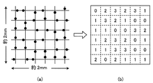
図2は、ドットパターンのドットとそのドットが変換される値との関係を示す図である。図2は、アノト方式のドットパターン(コード化パターン)を示している。図2に示すように、ドットパターンの各ドットは、その位置によって所定の値に対応付けられている。すなわち、ドットの位置を仮想格子の基準位置(縦線及び横線の交差点)から上下左右のどの方向にシフトするかによって、各ドットは、0〜3の値に対応付けられている。また、各ドットの値は、更に、X座標用の第1ビット値及びY座標用の第2ビット値に変換できる。このようにして対応付けられた情報の組合せにより、記入帳2の各頁上の位置座標が決定されるように構成されている。
FIG. 2 is a diagram illustrating a relationship between dots of a dot pattern and values to which the dots are converted. FIG. 2 shows an Anoto dot pattern (coding pattern). As shown in FIG. 2, each dot of the dot pattern is associated with a predetermined value depending on its position. That is, each dot is associated with a value of 0 to 3 depending on which direction the top, bottom, left, or right is shifted from the reference position of the virtual grid (the intersection of the vertical and horizontal lines). The value of each dot can be further converted into a first bit value for the X coordinate and a second bit value for the Y coordinate. The position coordinates on each page of the
記入帳2の頁同士では、座標領域が重ならないようにドットパターンが形成される。すなわち、各ドットパターンによって、同一頁内の位置座標の識別(例えば、そのドットパターンが記入帳2の各頁上のどの位置にあるのか)だけでなく、頁番号も識別可能である。
A dot pattern is formed between the pages of the
図3(a)は、ドットパターンを模式的に示し、図3(b)は、それに対応する情報の例を示す図である。図3(a)に示すように、縦横約2cmの範囲内に6×6個のドットが、記入帳2のどの部分から6×6ドットを取ってもユニークなパターンとなるように配置されている。これら36個のドットにより形成されるドットパターンは、頁番号と、各頁内の位置座標の情報を保持している。図3(b)は、図3(a)に示す規則性に基づいて対応付けられた値に変換したものである。この変換は、ドットパターンの画像を撮影する電子ペン1によって行われる。
FIG. 3A schematically illustrates a dot pattern, and FIG. 3B illustrates an example of information corresponding to the dot pattern. As shown in FIG. 3 (a), 6 × 6 dots are arranged in a range of about 2 cm in length and width so that a 6 × 6 dot from any part of the
図4は、電子ペン1の構造を示す概略図である。図4に示すように、電子ペン1は、その筐体101の内部に、インクカートリッジ104、LED105、CMOSカメラ106、圧力センサ107、CPU(Central Processing Unit)等により構成されるプロセッサ108、ROMやRAMといったメモリ109、リアルタイムクロック110、アンテナ等により構成される通信ユニット111及びバッテリー112を備える。インクカートリッジ104の先端は、ペン先部103となっており、ユーザは、電子ペン1のペン先部103を記入帳2の各頁に当接させて、ストローク(手書きストローク)を記入する。ここで、電子ペン1のペン先部103が記入帳2の各頁等に最初に接触することを「ペンダウン」と呼び、接触している(当接している)状態からペン先部103が離れることを「ペンアップ」と呼ぶ。電子ペン1のペンダウンからペンアップまでの間に記入される軌跡が1つのストロークとなり、文字や図形等は、1つ又は複数個のストロークからなる。
FIG. 4 is a schematic diagram showing the structure of the
バッテリー112は、電子ペン1内の各部品に電力を供給するためのものであり、例えば電子ペン1のキャップ(図示せず)の脱着により電子ペン1自体の電源のオン/オフを行うように構成してもよい。リアルタイムクロック110は、記入時刻(タイムスタンプ)を示す時刻情報を発信し、プロセッサ108に供給する。圧力センサ107は、ユーザが電子ペン1により記入帳2の各頁等に文字やマークを書く際にペン先部103からインクカートリッジ104を通じて与えられる圧力、即ち筆圧を検出し、その値をプロセッサ108へ伝送する。
The battery 112 is for supplying electric power to each component in the
プロセッサ108は、圧力センサ107から与えられる筆圧データに基づいて、LED105及びCMOSカメラ106のスイッチのオン/オフを切替える。即ち、ユーザが電子ペン1で記入帳2の各頁等に文字などを書くと、ペン先部103に筆圧がかかり、圧力センサ107によって所定値以上の筆圧が検出されたときに、プロセッサ108は、ユーザが記入を開始したと判定して、LED105及びCMOSカメラ106を作動させる。そして、通信ユニット111が、圧力センサ107により検出されたペンダウン情報と、後述する電子ペン1の識別情報(以後、「ペンID」と呼ぶ。)とを関連付けて、記入情報表示装置3へ送信する。また、ユーザが1つのストロークを記入し終えて電子ペン1を記入帳2の各頁等から離すと、圧力センサ107は、所定値以上の筆圧が検出されなくなることでペンアップを検出する。すると、通信ユニット111が、圧力センサ107により検出されたペンアップ情報とペンIDとを関連付けて、記入情報表示装置3へ送信する。
The processor 108 switches on / off the switches of the
LED105とCMOSカメラ106は、電子ペン1のペン先部103付近に取り付けられており、筐体101におけるLED105及びCMOSカメラ106と対向する部分には、開口部102が形成されている。LED105は、記入帳2の各頁上のペン先部103近傍に向けて赤外線を照明する。その領域は、ペン先部103が記入帳2の各頁等に接触する位置とはわずかにずれている。CMOSカメラ106には、赤外線を透過し赤外線以外を遮断する赤外線フィルタが設けられており、CMOSカメラ106は、LED105によって照明された領域内におけるドットパターンを撮影し、そのドットパターンの画像データをプロセッサ108に供給する。ここで、カーボンは赤外線を吸収するため、LED105によって照射された赤外線は、ドットに含まれるカーボンによって吸収される。そのため、ドットの部分は、赤外線の反射量が少なく、ドット以外の部分は赤外線の反射量が多い。CMOSカメラ106の撮影により、赤外線の反射量の違いから閾値を設けることによって、カーボンを含むドットの領域とそれ以外の領域を区別することができる。したがって、記入帳2の各頁に文字や図面などが印刷されていた場合でも、印刷したインクは赤外域に吸収性を持たないため、プロセッサ108は、ドットパターンを認識することができる。なお、CMOSカメラ106による撮影領域は、図3(a)に示すような約2mm×約2mmの大きさを含む範囲であり、CMOSカメラ106の撮影は毎秒50〜100回程度の定間隔で行われる。また、CMOSカメラ106は、ドットを鮮明に撮影するため、十分な被写界深度を有している。
The
プロセッサ108は、ユーザの記入が行われる間、CMOSカメラ106によって供給される画像データのドットパターンから、ユーザが記入するストローク(筆跡)の記入帳2の各頁等におけるX、Y座標(以後、単に「座標データ」とも呼ぶ。)を連続的に演算していく。すなわち、プロセッサ108は、CMOSカメラ106によって供給される、図3(a)に示されるようなドットパターンの画像データを図3(b)に示すデータ配列に変換し、さらに、X座標ビット値・Y座標ビット値に変換して、そのデータ配列から所定の演算方法により座標データを演算する。なお、プロセッサ108は、ドットパターンに対向する電子ペン1の角度に起因するドットの画像上の配列を補正する回転補正処理機能を備えており、座標演算の際にその機能が実行される。そして、プロセッサ108は、リアルタイムクロック110から発信される記入時刻(タイムスタンプ)、筆圧データ及び座標データを対応付ける。以後、これらの関連付けたデータを、まとめて「座標属性情報」と呼ぶ。なお、記入帳2の各頁における6×6のドットパターンは、記入帳2で重複することはないため、ユーザが電子ペン1で文字等を記入すると、記入された位置が記入帳2の各頁のどの位置に当たるかを、プロセッサ108による座標演算により特定することができる。
While the user performs the entry, the processor 108 determines the X and Y coordinates (hereinafter referred to as “X” and “Y” coordinates in each page of the
メモリ109には、電子ペン1を識別するための「pen01」といったペンID、ペン製造者番号、ペンソフトウェアのバージョン等のプロパティ情報が記憶されている。そして、通信ユニット111は、ペンIDと、記入時刻(タイムスタンプ)と、筆圧データと、座標データとを関連付けて、記入情報表示装置3へ送信する。この場合の通信ユニット111による記入情報表示装置3への送信は、Bluetooth(登録商標)などの無線送信によって、即時的かつ逐次的に行われる。ここで、電子ペン1のペンダウンからペンアップまでの間に生成されて記入情報表示装置3に送信された1個又は複数個の座標属性情報は、記入情報表示装置3に記憶される。換言すると、1つのストロークは、1個又は複数個のX、Y座標(座標点)からなり、記入情報表示装置3は、ペンダウン情報及びペンアップ情報によって、1つのストロークを構成する1個又は複数個の座標属性情報を認識する。
以降、電子ペン1のペンダウンからペンアップまでの間に生成されて記入情報表示装置3に送信される1個又は複数個の座標属性情報を「記入情報」と呼ぶ。
The memory 109 stores property information such as a pen ID such as “pen01” for identifying the
Hereinafter, one or a plurality of coordinate attribute information generated from the pen down to the pen up of the
なお、電子ペン1は、インクカートリッジ104に代えて、インキが充填されていないペン部を備えてもよい。
The
図5は、記入情報表示装置3のハードウエア構成図である。なお、図5のハードウエア構成は一例である。記入情報表示装置3は、用途、目的に応じて様々な構成を採ることが可能であり、デスクトップPC(Personal Computer)、ノートPC、タブレットPC、スマートフォン等のいずれであっても良い。
FIG. 5 is a hardware configuration diagram of the entry
図5に示すように、記入情報表示装置3は、制御部31、記憶部32、メディア入出力部33、通信制御部34、入力部35、表示部36、周辺機器I/F部37等が、バス38を介して接続される。
As shown in FIG. 5, the entry
制御部31は、CPU(Central Processing Unit)、ROM(Read Only Memory)、RAM(Random Access Memory)等によって構成される。CPUは、記憶部32、ROM、記録媒体等に格納されるプログラムをRAM上のワークメモリ領域に呼び出して実行し、バス38を介して接続された各装置を駆動制御し、記入情報表示装置3が行う後述する処理を実現する。ROMは、不揮発性メモリであり、コンピュータのブートプログラムやBIOS等のプログラム、データ等を恒久的に保持している。RAMは、揮発性メモリであり、記憶部32、ROM、記録媒体等からロードしたプログラム、データ等を一時的に保持するとともに、制御部31が各種処理を行う為に使用するワークエリアを備える。
The
記憶部32は、HDD(Hard Disk Drive)等であり、制御部31が実行するプログラム、プログラム実行に必要なデータ、OS(Operating System)等が格納される。プログラムに関しては、OSに相当する制御プログラムや、後述する処理をコンピュータに実行させるためのアプリケーションプログラムが格納されている。これらの各プログラムコードは、制御部31により必要に応じて読み出されてRAMに移され、CPUに読み出されて各種の手段として実行される。
The
メディア入出力部33(ドライブ装置)は、データの入出力を行い、例えば、CDドライブ(−ROM、−R、−RW等)、DVDドライブ(−ROM、−R、−RW等)等のメディア入出力装置を有する。通信制御部34は、通信制御装置、通信ポート等を有し、コンピュータとネットワーク間の通信を媒介する通信インタフェースであり、ネットワークを介して、他のコンピュータ間との通信制御を行う。ネットワークは、有線、無線を問わない。
The media input / output unit 33 (drive device) inputs / outputs data, for example, media such as a CD drive (-ROM, -R, -RW, etc.), DVD drive (-ROM, -R, -RW, etc.) Has input / output devices. The
入力部35は、データの入力を行い、例えば、キーボード、マウス等のポインティングデバイス、テンキー等の入力装置を有する。入力部35を介して、コンピュータに対して、操作指示、動作指示、データ入力等を行うことができる。表示部36は、液晶パネル等のディスプレイ装置、ディスプレイ装置と連携してコンピュータのビデオ機能を実現するための論理回路等(ビデオアダプタ等)を有する。尚、入力部35及び表示部36は、タッチパネルディスプレイのように、一体となっていても良い。
The
周辺機器I/F(Interface)部37は、コンピュータと周辺機器とのデータ送受信を行うためのポートやアンテナ等であり、コンピュータは周辺機器I/F部37を介して周辺機器とのデータの送受信を行う。周辺機器との接続形態は、有線(例えば、USB(Universal Serial Bus)等)、無線(例えば、Bluetooth(登録商標)等)を問わない。バス38は、各装置間の制御信号、データ信号等の授受を媒介する経路である。
The peripheral device I / F (Interface)
図6は、記憶部32に記憶される「座標定義情報」のデータ構造の一例を示す図である。座標定義情報とは、記入帳2の各頁に印刷されたドットパターンが示す座標範囲の情報を示すものである。図6の例では、座標定義情報は、記入帳2の頁ごとに、記入帳2の種類を識別するための記入帳IDを示す項目と、頁番号を示す項目と、記入帳2の頁に印刷されたドットパターンの座標範囲を示す項目とを含む。なお、ここでは、図1に示す記入帳2の記入帳IDは「N01」とし、座標範囲は、角の位置情報(Xn、Yn)、高さ(Y方向)、幅(X方向)で規定されている。
FIG. 6 is a diagram illustrating an example of a data structure of “coordinate definition information” stored in the
図7は、アップロード処理を示すフローチャートである。図7に示すように、電子ペン1の通信ユニット111から記入情報が送信されると、記入情報表示装置3の制御部31は、周辺機器I/F部37を介して記入情報を受信し(ステップS11)、受信した記入情報をペンIDごとに記憶部32に記憶する(ステップS12)。このとき、制御部31は、図6に示す記入帳2の座標定義情報を参照し、記入情報を頁番号と関連付けて、記憶部32に記憶する。
FIG. 7 is a flowchart showing the upload process. As shown in FIG. 7, when entry information is transmitted from the communication unit 111 of the
なお、ステップS12の変形例として、制御部31は、電子ペン1から受信する記入情報を、通信制御部34及びネットワークを介して、図示しないサーバに送信し、サーバの記憶装置に記憶させるようにしても良い。この場合、制御部31は、必要に応じて、サーバの記憶装置から記入情報を取得する。
As a modification of step S12, the
また、電子ペン1が、インクカートリッジ104に代えて、インキが充填されていないペン部を備えている場合、制御部31は、一時的にRAMに記入情報を記憶するようにしても良い。この場合、制御部31は、RAMに記憶する記入情報を即時的に表示部36に表示するようにしても良い。そして、制御部31は、ユーザからの求めに応じて、記憶部32に記入情報を記憶したり、サーバの記憶装置に記憶させたりしても良い。以下では、制御部31は、記憶部32に記入情報を記憶するものとして説明する。
When the
図8は、記入情報表示装置3の表示制御処理を示すフローチャートである。
FIG. 8 is a flowchart showing the display control process of the entry
最初に、制御部31は、記憶部32から記入情報の記入時点及び記入頁を取得する(ステップS21)。記入時点とは、各記入情報が記入された日付や時刻等の情報である。記入頁とは、各記入情報が記入された頁の情報である。制御部31は、記憶部32から、記入情報ごとの記入頁として頁番号を取得し、記入情報ごとの記入時点として記入時刻(タイムスタンプ)を取得する。
First, the
ステップS21の変形例として、制御部31は、頁ごとに少なくとも1つ記入される日付を文字認識処理によって認識し、同一頁に含まれる記入情報ごとの記入時点として取得するようにしても良い。この場合、日付記入ルールとして、記入箇所(例えば、各頁に記入される罫線の左側)や記入態様(例えば、「月/日」)を定めておけば、精度良く文字認識処理を行うことができる。
As a modification of step S21, the
なお、通常の光学文字認識処理(OCR:Optical Character
Recognition)と比較すると、図7に示すアップロード処理がイメージスキャナを用いた取込処理に相当するので、本発明の実施の形態では、制御部31は、パターンマッチング処理(予め記憶されている文字パターンとの照合)のみを行うだけでよい。
Normal optical character recognition processing (OCR: Optical Character
Compared with Recognition, the upload process shown in FIG. 7 corresponds to a capture process using an image scanner. Therefore, in the embodiment of the present invention, the
次に、制御部31は、記入時点が表示対象の単位期間内に含まれる記入情報が複数頁に存在するか否か判定する(ステップS22)。単位期間は、例えば、1時間、半日、1日、1週間等である。ステップS22の判定がNoの場合、制御部31は、単一頁表示を行うように制御し(ステップS23)、ステップS22の判定がYesの場合、制御部31は、複数頁表示を行うように制御する(ステップS24)。換言すると、制御部31は、記入時点を参照し、単一頁表示と複数頁表示を切り替える。複数頁表示とは、表示部36において複数頁を同時に並べて表示することを意味する。
Next, the
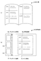
図9は、単一頁表示の一例を示す図である。図9(a)は、記入帳2aの模式図である。図9(b)は、表示部36に表示される表示画面4aの模式図である。表示画面4aは、サムネイル領域41とメイン領域42に分かれており、サムネイル領域41にはサムネイル画像43a〜43cが表示され、メイン領域42には詳細画像44aが表示されている。
FIG. 9 is a diagram illustrating an example of single page display. FIG. 9A is a schematic diagram of the entry book 2a. FIG. 9B is a schematic diagram of the display screen 4 a displayed on the
図9(a)に示す記入帳2aには、見開き2頁のうち、左側の頁において、2月2日、2月3日及び2月7日に記入情報が記入され、右側の頁において、2月12日及び2月15日に記入情報が記入されている。 In the entry book 2a shown in FIG. 9A, entry information is entered on February 2, February 3, and February 7 on the left side of the two spread pages, and on the right page, The entry information is entered on February 12 and February 15.
表示対象の単位期間を1日とし、記入帳2aの左側の頁を表示するとする。この場合、制御部31は、記入時点が表示対象の単位期間内に含まれる記入情報が複数頁に存在しないと判定し、図9(b)に示すように、単一頁表示を行うように制御する。図9(b)では、詳細画像44aとして、記入帳2aの左側の頁に対応する画像が表示されている。
Assume that the unit period to be displayed is one day, and the page on the left side of the entry book 2a is displayed. In this case, the
なお、実験ノートにおいては、実験が行われた日付ごとに頁を分けて記入することが一般的であるものの、図9(b)に示す例のように、同一頁内に異なる日付による記入情報が含まれていても、本発明を適用することができる。 In the experiment note, although it is common to divide and fill in pages for each date on which the experiment was conducted, as in the example shown in FIG. Even if is included, the present invention can be applied.
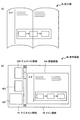
図10は、複数頁表示の一例を示す図である。図10(a)は、記入帳2bの模式図である。図10(b)は、表示部36に表示される表示画面4bの模式図である。図10(a)に示す記入帳2bには、見開き2頁に跨って、3月4日に記入情報(図表)が記入されている。
FIG. 10 is a diagram illustrating an example of a multi-page display. FIG. 10A is a schematic diagram of the entry book 2b. FIG. 10B is a schematic diagram of the display screen 4 b displayed on the
表示対象の単位期間を1日とし、記入帳2bの左側(又は右側)の頁を表示するとする。この場合、制御部31は、記入時点が表示対象の単位期間内に含まれる記入情報が複数頁に存在すると判定し、図10(b)に示すように、複数頁表示を行うように制御する。図10(b)では、詳細画像44bとして、記入帳2bの見開き2頁に対応する画像が表示されている。
Assume that the unit period to be displayed is one day, and the left (or right) page of the entry 2b is displayed. In this case, the
図11は、複数頁表示の他の例を示す図である。図11(a)は、記入帳2cの模式図である。図11(b)は、表示部36に表示される表画面4cの模式図である。図11(a)に示す記入帳2cには、見開き2頁に跨って、2月2日、2月3日、及び2月7日の記入情報が記入されている。
FIG. 11 is a diagram illustrating another example of a multi-page display. FIG. 11A is a schematic diagram of the entry book 2c. FIG. 11B is a schematic diagram of the front screen 4 c displayed on the
表示対象の単位期間を6日とし、記入帳2cの左側(又は右側)の頁を表示するとする。この場合、制御部31は、記入時点が表示対象の単位期間内に含まれる記入情報が複数頁に存在すると判定し、図11(b)に示すように、複数頁表示を行うように制御する。図11(b)では、詳細画像44cとして、記入帳2cの見開き2頁に対応する画像が表示されている。
Assume that the unit period to be displayed is 6 days, and the left (or right) page of the entry 2c is displayed. In this case, the
なお、図10(b)及び図11(b)に示す例では、見開き2頁を同時に並べて表示するものとしたが、本発明はこれに限定されない。例えば、見開き以外の2頁を同時に並べて表示するようにしても良いし、3頁以上を同時に並べて表示するようにしても良い。但し、頁数が多すぎると視認性が悪くなるため、同時表示の頁数に上限を設定できるようにしても良い。 In the example shown in FIGS. 10B and 11B, two spread pages are displayed side by side at the same time, but the present invention is not limited to this. For example, two pages other than the spread may be displayed side by side at the same time, or three or more pages may be displayed side by side at the same time. However, if the number of pages is too large, the visibility deteriorates, so an upper limit may be set for the number of pages displayed simultaneously.
以上、記入情報表示装置3は、記入情報の記入時点及び記入頁を取得し、記入時点を参照し、単一頁表示と複数頁表示を切り替える。これによって、必要に応じて自動的に複数頁表示を行うことができる。
As described above, the entry
また、記入情報表示装置3は、記入時点が同一の単位期間内に含まれる記入情報が複数頁に存在する場合には、複数頁表示を行うように制御する。これによって、実験ノートのように、通常は日付ごとに頁を分けて記入するものの、大きい図表などを見開きの2頁分に跨って記入することがある場合であっても、適切に単一頁表示と複数頁表示を切り替えて表示することができる。
Further, the entry
また、記入情報表示装置3は、電子ペン1から受信する記入時刻を記入情報ごとの記入時点として取得するようにしても良い。これによって、記入時点を正確に取得することができる。
The entry
また、記入情報表示装置3は、頁ごとに少なくとも1つ記入される日付を文字認識処理によって認識し、同一頁に含まれる入情報ごとの記入時点として取得するようにしても良い。これによって、リアルタイムクロック110を有しない電子ペン1を使用する場合や、電子ペン1を使用しない場合であっても、本発明を適用することができる。
Further, the entry
なお、前述の説明では、記入帳2が紙媒体としたが、記入帳2は、紙媒体に代えて、タッチパネルディスプレイを有するタブレット端末等であっても良い。記入帳2がタブレット端末等である場合、電子ペン1は、インキが充填されていないペン部を備える。この場合の構成例としては、例えば、特開2014−219929号公報に記載されており、前述の記入帳2が紙媒体の場合と同様に本発明を適用することができる。
In the above description, the
以上、添付図面を参照しながら、本発明に係る記入情報表示装置等の好適な実施形態について説明したが、本発明はかかる例に限定されない。当業者であれば、本願で開示した技術的思想の範疇内において、各種の変更例又は修正例に想到し得ることは明らかであり、それらについても当然に本発明の技術的範囲に属するものと了解される。 The preferred embodiments of the entry information display device and the like according to the present invention have been described above with reference to the accompanying drawings, but the present invention is not limited to such examples. It will be apparent to those skilled in the art that various changes or modifications can be conceived within the scope of the technical idea disclosed in the present application, and these naturally belong to the technical scope of the present invention. Understood.
1………電子ペン
2、2a、2b、2c………記入帳
3………記入情報表示装置
31………制御部
32………記憶部
33………メディア入出力部
34………通信制御部
35………入力部
36………表示部
37………周辺機器I/F部
4a、4b、4c………表示画面
41………サムネイル領域
42………メイン領域
43a、43b、43c、43d、43e、43f、43g、43h、43i………サムネイル画像
44a、44b、44c………詳細画像
DESCRIPTION OF
Claims (6)
前記記入情報の記入時点及び記入頁を取得する取得手段と、
前記記入時点を参照し、単一頁表示と複数頁表示を切り替える表示制御手段と、
を有することを特徴とする記入情報表示装置。 An entry information display device for displaying entry information entered in an entry book having a plurality of pages,
Acquisition means for acquiring the entry time and entry page of the entry information;
Display control means for switching between single page display and multiple page display with reference to the entry time point,
An entry information display device characterized by comprising:
ことを特徴とする請求項1に記載の記入情報表示装置。 2. The display control means according to claim 1, wherein the plurality of pages are displayed when the entry information included in the same unit period is included in the plurality of pages. A written information display device.
ことを特徴とする請求項1又は請求項2に記載の記入情報表示装置。 The entry information display according to claim 1 or 2, wherein the acquisition means acquires an entry time received from an electronic pen used for entry of the entry information as the entry time for each entry information. apparatus.
ことを特徴とする請求項1又は請求項2に記載の記入情報表示装置。 2. The acquisition unit according to claim 1, wherein the acquisition unit recognizes at least one date written on each page by character recognition processing, and acquires the date as the entry time for each of the entry information included in the same page. 2. The entry information display device according to 2.
前記コンピュータの制御部が、
前記記入情報の記入時点及び記入頁を取得する取得ステップと、
前記記入時点を参照し、単一頁表示と複数頁表示を切り替える表示制御ステップと、
を実行することを特徴とする記入情報表示方法。 An entry information display method in which a computer displays entry information entered in an entry book having a plurality of pages,
A control unit of the computer,
An acquisition step of acquiring the entry time and entry page of the entry information;
A display control step of switching between single page display and multiple page display with reference to the entry time point;
Entry information display method characterized by executing
前記コンピュータを、
前記記入情報の記入時点及び記入頁を取得する取得手段と、
前記記入時点を参照し、単一頁表示と複数頁表示を切り替える表示制御手段として機能させるためのプログラム。 A program for causing a computer to function as an entry information display device for displaying entry information entered in an entry book having a plurality of pages,
The computer,
Acquisition means for acquiring the entry time and entry page of the entry information;
A program for functioning as display control means for switching between single-page display and multi-page display with reference to the entry point.
Priority Applications (1)
| Application Number | Priority Date | Filing Date | Title |
|---|---|---|---|
| JP2014242911A JP6375903B2 (en) | 2014-12-01 | 2014-12-01 | Entry information display device, entry information display method and program |
Applications Claiming Priority (1)
| Application Number | Priority Date | Filing Date | Title |
|---|---|---|---|
| JP2014242911A JP6375903B2 (en) | 2014-12-01 | 2014-12-01 | Entry information display device, entry information display method and program |
Publications (2)
| Publication Number | Publication Date |
|---|---|
| JP2016105227A JP2016105227A (en) | 2016-06-09 |
| JP6375903B2 true JP6375903B2 (en) | 2018-08-22 |
Family
ID=56102493
Family Applications (1)
| Application Number | Title | Priority Date | Filing Date |
|---|---|---|---|
| JP2014242911A Expired - Fee Related JP6375903B2 (en) | 2014-12-01 | 2014-12-01 | Entry information display device, entry information display method and program |
Country Status (1)
| Country | Link |
|---|---|
| JP (1) | JP6375903B2 (en) |
Family Cites Families (4)
| Publication number | Priority date | Publication date | Assignee | Title |
|---|---|---|---|---|
| JP2012103818A (en) * | 2010-11-08 | 2012-05-31 | Rakuten Inc | Electronic book delivery system, electronic book delivery method, client device, electronic book delivery device, program, and information recording medium |
| JP2012252214A (en) * | 2011-06-03 | 2012-12-20 | Sharp Corp | Content display device, method for displaying content, and program for causing computer to function as content display device |
| JP5915118B2 (en) * | 2011-11-25 | 2016-05-11 | 大日本印刷株式会社 | Archive system, first terminal and program |
| JP2014086053A (en) * | 2012-10-26 | 2014-05-12 | Brother Ind Ltd | Information management device and information management program |
-
2014
- 2014-12-01 JP JP2014242911A patent/JP6375903B2/en not_active Expired - Fee Related
Also Published As
| Publication number | Publication date |
|---|---|
| JP2016105227A (en) | 2016-06-09 |
Similar Documents
| Publication | Publication Date | Title |
|---|---|---|
| JP2007128484A (en) | User interface executed by computer | |
| CN103473012A (en) | Screen capturing method, device and terminal equipment | |
| JP5664164B2 (en) | Electronic information board device, information display method, program | |
| JP6044198B2 (en) | Computer apparatus, program, and information processing system | |
| US10684772B2 (en) | Document viewing apparatus and program | |
| US20140147047A1 (en) | Electronic device and method for processing handwritten document | |
| JPWO2015087379A1 (en) | Electronic device and method for processing handwritten document information | |
| CN104956378A (en) | Electronic apparatus and handwritten-document processing method | |
| JP6375903B2 (en) | Entry information display device, entry information display method and program | |
| JP5884364B2 (en) | Computer apparatus and program | |
| JP3174897U (en) | Teaching material content display system, computer apparatus thereof, and sheet used therefor | |
| JP4748280B1 (en) | Computer apparatus and program thereof | |
| US20140232667A1 (en) | Electronic device and method | |
| JP2014199525A (en) | Computer device and program | |
| JP6048165B2 (en) | Computer apparatus, electronic pen system, and program | |
| JP5831091B2 (en) | Computer apparatus and program | |
| EP2879029A1 (en) | Coordinate detection system, information processing apparatus, and recording medium | |
| JP6418016B2 (en) | Handwriting collection system, handwriting collection method, program | |
| US10070066B2 (en) | Coordinate calculator and coordinate calculation system | |
| JP2013020402A (en) | Computer device, stroke display system and program | |
| JP2017071136A (en) | Booklet and content creation system | |
| JP6465414B2 (en) | Electronic device, method and program | |
| JP2016105229A (en) | Entry information display device, entry information display method, and program | |
| TW201530363A (en) | Electro-signature system and method using touch stick | |
| JP3196255U (en) | Entry book |
Legal Events
| Date | Code | Title | Description |
|---|---|---|---|
| A621 | Written request for application examination |
Free format text: JAPANESE INTERMEDIATE CODE: A621 Effective date: 20171030 |
|
| TRDD | Decision of grant or rejection written | ||
| A977 | Report on retrieval |
Free format text: JAPANESE INTERMEDIATE CODE: A971007 Effective date: 20180613 |
|
| A01 | Written decision to grant a patent or to grant a registration (utility model) |
Free format text: JAPANESE INTERMEDIATE CODE: A01 Effective date: 20180626 |
|
| A61 | First payment of annual fees (during grant procedure) |
Free format text: JAPANESE INTERMEDIATE CODE: A61 Effective date: 20180709 |
|
| R150 | Certificate of patent or registration of utility model |
Ref document number: 6375903 Country of ref document: JP Free format text: JAPANESE INTERMEDIATE CODE: R150 |
|
| LAPS | Cancellation because of no payment of annual fees |