JP6374331B2 - Engine oil level detector - Google Patents
Engine oil level detector Download PDFInfo
- Publication number
- JP6374331B2 JP6374331B2 JP2015032137A JP2015032137A JP6374331B2 JP 6374331 B2 JP6374331 B2 JP 6374331B2 JP 2015032137 A JP2015032137 A JP 2015032137A JP 2015032137 A JP2015032137 A JP 2015032137A JP 6374331 B2 JP6374331 B2 JP 6374331B2
- Authority
- JP
- Japan
- Prior art keywords
- engine
- oil level
- oil
- time
- level
- Prior art date
- Legal status (The legal status is an assumption and is not a legal conclusion. Google has not performed a legal analysis and makes no representation as to the accuracy of the status listed.)
- Active
Links
Images


Landscapes
- Lubrication Details And Ventilation Of Internal Combustion Engines (AREA)
Description
本発明は、例えば車両に設けられたオイルパン等のオイル貯留槽におけるエンジンオイルの油面位置を検出するエンジンオイルのレベル検出装置についての技術分野に関する。 The present invention relates to a technical field of an engine oil level detection device that detects an oil level position of engine oil in an oil reservoir such as an oil pan provided in a vehicle.
車両のエンジン下方に設けられたオイルパン等、エンジンオイル(潤滑油)をエンジンとの間で循環可能に貯留するオイル貯留槽におけるエンジンオイルの油面位置を検出するエンジンオイルのレベル検出装置が知られている(例えば、上記特許文献1、2を参照)。
An engine oil level detection device that detects the oil level of an engine oil in an oil storage tank that stores engine oil (lubricating oil) in a circulating manner with the engine, such as an oil pan provided below a vehicle engine, is known. (See, for example,
上記特許文献1には、エンジンオイルの油面位置をFull/Lowの2値ではなく、3値以上の多値により検出可能な技術が開示されている。具体的に、特許文献1には、オイルタンク内においてオイル面上に浮くフロートと、上下方向に配列されフロートが近接するとオンされる複数のリードスイッチ(以下「オイルレベルスイッチ」と表記)とを備え、オン状態とされたオイルレベルスイッチの数に基づき油面位置を多値検出する技術が開示されている。
しかしながら、オイルレベルスイッチを複数設けることはコストアップに繋がり望ましくない。 However, providing a plurality of oil level switches is undesirable because it leads to an increase in cost.
そこで、本発明では上記した問題点を克服し、オイル貯留槽におけるエンジンオイルの油面位置を多値検出するエンジンオイルのレベル検出装置について、コスト削減を図ることを目的とする。 Therefore, the present invention aims to overcome the above-described problems and to reduce the cost of an engine oil level detection device that multi-values the oil level position of the engine oil in the oil storage tank.
本発明に係るエンジンオイルのレベル検出装置は、エンジンオイルをエンジンとの間で循環可能に貯留するオイル貯留槽における前記エンジンオイルの油面位置を検出するエンジンオイルのレベル検出装置であって、前記油面位置が所定レベルに達したことに応じてオンされるオイルレベルスイッチと、前記エンジンが停止された時点を基準とした基準時点から前記オイルレベルスイッチがオンするまでの時間を計測し、計測した前記時間に基づき前記油面位置を推定するオイルレベル推定部と、を備えるものである。 The engine oil level detection device according to the present invention is an engine oil level detection device that detects an oil level position of the engine oil in an oil storage tank that stores the engine oil so as to be circulated with the engine, The oil level switch that is turned on in response to the oil level position reaching a predetermined level, and the time from when the engine is stopped to the time when the oil level switch is turned on are measured and measured. And an oil level estimation unit that estimates the oil level position based on the time.
これにより、エンジンオイル油面位置の多値検出にあたり複数のオイルレベルスイッチを設ける必要がない。 Thereby, it is not necessary to provide a plurality of oil level switches for multi-value detection of the engine oil oil level position.
上記した本発明に係るエンジンオイルのレベル検出装置においては、前記オイルレベル推定部は、前記基準時点からオイルレベルスイッチがオンするまでの時間と前記油面位置との対応関係を表す時間・油面位置対応情報に基づき前記油面位置を推定することが望ましい。
上記のような時間と油面位置との対応関係を表す時間・油面位置対応情報を用いることで、エンジンオイル油面位置の推定を比較的簡易に行うことが可能である。
In the engine oil level detection device according to the present invention described above, the oil level estimation unit is a time / oil level representing a correspondence relationship between a time from the reference time point until the oil level switch is turned on and the oil level position. It is desirable to estimate the oil level position based on position correspondence information.
By using the time / oil surface position correspondence information representing the correspondence between the time and the oil surface position as described above, it is possible to estimate the engine oil oil surface position relatively easily.
上記した本発明に係るエンジンオイルのレベル検出装置においては、前記オイルレベル推定部は、前記基準時点から前記オイルレベルスイッチがオンするまでの時間として想定される各時間ごとに前記油面位置の情報が対応づけられたテーブル情報としての前記時間・油面位置対応情報に基づき前記油面位置を推定することが望ましい。
これにより、エンジンオイル油面位置の推定は、上記のテーブル情報から計測時間に対応するエンジンオイルの油面位置情報を取得するのみで実現される。
In the engine oil level detection device according to the present invention described above, the oil level estimation unit is configured to provide information on the oil level position at each time assumed as a time from the reference time point until the oil level switch is turned on. It is desirable to estimate the oil level position based on the time / oil level position correspondence information as table information associated with.
Thereby, the estimation of the engine oil oil level position is realized only by acquiring the oil level position information of the engine oil corresponding to the measurement time from the table information.
上記した本発明に係るエンジンオイルのレベル検出装置においては、前記オイルレベル推定部は、前記エンジンの前記停止までの作動時間、前記エンジンの前記停止の直前における回転数、前記オイル貯留槽が設けられた車両に作用している加速度、又は前記エンジンオイルの温度の少なくとも何れかが予め定められた想定値を逸脱しているか否かを判定し、前記想定値を逸脱している場合は前記油面位置の推定を行わないことが望ましい。
エンジンの停止までの作動時間、エンジンの停止直前における回転数、オイル貯留槽が設けられた車両に作用している加速度、又はエンジンオイルの温度は、基準時点からオイルレベルスイッチがオンするまでの時間とエンジンオイル油面位置との対応関係を変化させる要素であり、これらの要素が想定値を逸脱している場合に油面位置の推定を行わないことで、エンジンオイル油面位置の検出精度の低下防止が図られる。
In the engine oil level detection device according to the present invention described above, the oil level estimation unit is provided with an operation time until the engine stops, a rotational speed immediately before the engine stop, and the oil storage tank. It is determined whether at least one of the acceleration acting on the vehicle or the temperature of the engine oil deviates from a predetermined assumed value. It is desirable not to perform position estimation.
The operating time until the engine stops, the number of revolutions immediately before the engine stops, the acceleration acting on the vehicle provided with the oil storage tank, or the temperature of the engine oil is the time from the reference time until the oil level switch is turned on. The engine oil level position detection accuracy is improved by not estimating the oil level position when these factors deviate from the assumed values. Reduction can be prevented.
上記した本発明に係るエンジンオイルのレベル検出装置においては、前記オイルレベル推定部は、前記基準時点から前記オイルレベルスイッチがオンするまでの時間と、前記エンジンの前記停止までの作動時間、前記エンジンの前記停止の直前における回転数、前記オイル貯留槽が設けられた車両に作用している加速度、又は前記エンジンオイルの温度の少なくとも何れかとの組み合わせに対する前記油面位置の対応関係を表した前記時間・油面位置対応情報に基づき、前記油面位置を推定することが望ましい。
これにより、基準時点からオイルレベルスイッチがオンするまでの時間に基づくエンジンオイル油面位置の推定が、当該基準時点からオイルレベルスイッチがオンするまでの時間とエンジンオイル油面位置との対応関係を変化させる要素を加味した形で行われる。
In the engine oil level detection device according to the present invention described above, the oil level estimation unit includes a time from the reference time until the oil level switch is turned on, an operation time until the engine is stopped, the engine The time representing the correspondence relationship of the oil level position to a combination of at least one of the rotational speed immediately before the stop, the acceleration acting on the vehicle provided with the oil storage tank, and the temperature of the engine oil It is desirable to estimate the oil level position based on the oil level position correspondence information.
As a result, the estimation of the engine oil oil level position based on the time from the reference time point until the oil level switch is turned on indicates the correspondence between the time from the reference time point until the oil level switch is turned on and the engine oil oil level position. It is done in a form that takes into account the changing elements.
本発明によれば、オイル貯留槽におけるエンジンオイルの油面位置を多値検出するエンジンオイルのレベル検出装置について、複数のオイルレベルスイッチを設ける必要がなくなり、コスト削減を図ることができる。 According to the present invention, it is not necessary to provide a plurality of oil level switches in the engine oil level detection device that multi-values the oil level position of the engine oil in the oil storage tank, and the cost can be reduced.
<1.車両制御装置の全体構成>
図1は、本発明に係る実施の形態としてのエンジンオイルのレベル検出装置を備えた車両制御装置1の構成概要を示したブロック図である。なお、図1では、車両制御装置1の構成のうち主に本発明に係る要部の構成のみを抽出して示している。
エンジンオイルのレベル検出装置は、図1に示す構成要素のうち、少なくともエンジン制御部3とオイルレベルスイッチ10dとを備えるものである。
<1. Overall Configuration of Vehicle Control Device>
FIG. 1 is a block diagram showing an outline of the configuration of a
The engine oil level detection device includes at least the
車両制御装置1は、表示制御部2、エンジン制御部3、トランスミッション制御部4、ブレーキ制御部5、表示部6、エンジン関連アクチュエータ7、トランスミッション関連アクチュエータ8、ブレーキ関連アクチュエータ9、センサ・操作子類10、及びバス11を備えて構成されている。
The
センサ・操作子類10は、車両に設けられた各種のセンサや操作子を包括的に表している。センサ・操作子類10が有するセンサとしては、自車両の速度を車速として検出する速度センサ10a、エンジンの回転数を検出するエンジン回転数センサ10b、アクセルペダルの踏込み量からアクセル開度を検出するアクセル開度センサ10cがある。また、エンジンの潤滑油として機能するエンジンオイルEoのレベルが所定レベルに達したことに応じてオンされるオイルレベルスイッチ10d、エンジンオイルEoの温度を油温として検出する油温センサ10e、エンジン冷却水の温度を水温として検出する水温センサ10f、自車両に作用する加速度を検出するGセンサ10g、及びブレーキペダルの操作/非操作に応じてON/OFFされるブレーキスイッチ10hがある。
また、図示は省略したが、センサ・操作子類10は、他のセンサとして、例えばエンジンへの吸入空気量を検出する吸入空気量センサ、吸気通路に介装されてエンジンの各気筒に供給する吸入空気量を調整するスロットル弁の開度を検出するスロットル開度センサ、車外の気温を検出する外気温センサ等も有する。
また、操作子としては、エンジンの始動/停止を指示するためのイグニッションスイッチや、自動変速機における自動変速モード/手動変速モードの選択や手動変速モード時におけるシフトアップ/ダウンの指示を行うためのセレクトレバーや、後述する表示部11に設けられたMFD(Multi Function Display)における表示情報の切り換えを行うための表示切換スイッチなどがある。
The sensors /
Although not shown, the sensor /
Further, as an operator, an ignition switch for instructing start / stop of the engine, an automatic transmission mode / manual transmission mode selection in the automatic transmission, and an up / down instruction in the manual transmission mode are given. There are a select lever, a display changeover switch for switching display information in an MFD (Multi Function Display) provided in the
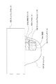
図2を参照して、センサ・操作子類10として設けられたオイルレベルスイッチ10dについて説明しておく。
オイルレベルスイッチ10dは、エンジンブロック100の下方に配置されたオイルパン101に対して設けられている。オイルパン101は、エンジンオイルEoをエンジンとの間で循環可能に貯留するオイル貯留槽である。
オイルパン101内には、上下方向(高さ方向)に延在する棒状ガイド101aと、輪状の外形を有し、中央の空洞部において棒状ガイド101aが挿通されたフロート101bとが設けられている。フロート101bは、エンジンオイルEoに対して浮力を有しており、オイルパン101内に貯留されたエンジンオイルEoの油面Seoが上下方向に変位することに応じて、棒状ガイド101aによりガイドされつつ上下方向に変位する。
オイルレベルスイッチ10dは、フロート101bが近接することに応じてオンされるスイッチである。すなわち、オイルレベルスイッチ10dは、エンジンオイルEoのレベル(油面Seoの高さ)が所定レベル(所定高さ)に達したことに応じてオンされる。
The
The
In the oil pan 101, there are provided a rod-shaped guide 101a extending in the vertical direction (height direction) and a float 101b having a ring-shaped outer shape and having the rod-shaped guide 101a inserted through a central cavity. . The float 101b has buoyancy with respect to the engine oil Eo, and is guided by the rod-shaped guide 101a according to the vertical displacement of the oil level Seo of the engine oil Eo stored in the oil pan 101. Displaces vertically.
The
説明を図1に戻す。
表示制御部2、エンジン制御部3、トランスミッション制御部4、及びブレーキ制御部5は、それぞれ、例えばCPU(Central Processing Unit)、ROM(Read Only Memory)、RAM(Random Access Memory)等を備えたマイクロコンピュータで構成され、互いがバス11を介してデータ通信可能に接続されている。表示部6、エンジン関連アクチュエータ7、トランスミッション関連アクチュエータ8、ブレーキ関連アクチュエータ9は、これら制御部の制御対象として設けられている。
Returning to FIG.
The
表示部6は、運転者の前方に設置されているメータパネル内に設けられたスピードメータやタコメータ等の各種メータやMFD、及びその他運転者に情報提示を行うための表示デバイスを包括的に表している。MFDには、自車両の総走行距離や外気温、瞬間燃費等といった各種の情報を同時又は切り換えて表示可能とされる。
The
表示制御部2は、センサ・操作子類10における例えば車速センサ10aやエンジン回転数センサ10b、前述した外気温センサ等の所定のセンサからの検出信号や操作子による操作入力情報等に基づき、表示部6による表示動作を制御する。
The
エンジン制御部3は、センサ・操作子類10における所定のセンサからの検出信号や操作子による操作入力情報等に基づき、エンジン関連アクチュエータ7として設けられた各種アクチュエータを制御する。エンジン関連アクチュエータ7としては、例えばスロットル弁を駆動するスロットルアクチュエータや燃料噴射を行うインジェクタ等のエンジン駆動に係る各種のアクチュエータが設けられる。
例えば、エンジン制御部3は、前述したイグニッションスイッチの操作に応じてエンジンの始動/停止制御を行う。また、エンジン制御部3は、エンジン回転数センサ10bやアクセル開度センサ10c等の所定のセンサからの検出信号に基づき、燃料噴射タイミング、燃料噴射パルス幅、スロットル開度等の制御も行う。
The
For example, the
また、本例におけるエンジン制御部3は、オイルレベルスイッチ10dによる検出情報に基づき、オイルパン101におけるエンジンオイルEoのレベル(油面Seo高さ)を検出する処理を行う。また、エンジン制御部3は、検出したエンジンオイルEoのレベル情報を表示制御部2に送信して表示部6に表示させる。
なお、オイルレベル検出手法については後述する。
In addition, the
The oil level detection method will be described later.
トランスミッション制御部4は、センサ・操作子類10における所定のセンサからの検出信号や操作子による操作入力情報等に基づき、トランスミッション関連アクチュエータ8として設けられた各種のアクチュエータを制御する。トランスミッション関連アクチュエータ8としては、例えば自動変速機の変速制御を行うためのアクチュエータが設けられる。
例えば、トランスミッション制御部4は、前述したセレクトレバーによって自動変速モードが選択されている際には、所定の変速パターンに従い変速信号を上記のアクチュエータに出力して変速制御を行う。また、トランスミッション制御部4は、手動変速モードの設定時には、セレクトレバーによるシフトアップ/ダウン指示に従った変速信号を上記のアクチュエータに出力して変速制御を行う。
The transmission control unit 4 controls various actuators provided as the transmission-related
For example, when the automatic shift mode is selected by the above-described select lever, the transmission control unit 4 performs a shift control by outputting a shift signal to the actuator according to a predetermined shift pattern. Further, when the manual shift mode is set, the transmission control unit 4 performs a shift control by outputting a shift signal according to a shift up / down instruction from the select lever to the actuator.
ブレーキ制御部5は、センサ・操作子類10における所定のセンサからの検出信号や操作子による操作入力情報等に基づき、ブレーキ関連アクチュエータ9として設けられた各種のアクチュエータを制御する。ブレーキ関連アクチュエータ9としては、例えば、ブレーキブースターからマスターシリンダへの出力液圧やブレーキ液配管内の液圧をコントロールするための液圧制御アクチュエータ等、ブレーキ関連の各種のアクチュエータが設けられる。例えば、ブレーキ制御部5は、所定のセンサ(例えば車軸の回転速度センサや車速センサ10a)の検出情報から車輪のスリップ率を計算し、スリップ率に応じて上記の液圧制御アクチュエータにより液圧を加減圧させることで、所謂ABS(Antilock Brake System)制御を実現する。
The
<2.オイルレベル検出手法の概要>
図3は、実施の形態のオイルレベル検出手法についての説明図であり、エンジン停止前後における経過時間と油面Seoの高さとの関係を例示している。具体的に、図3では、エンジン停止前(つまりエンジン作動中)における油面Seoの高さがSb1、Sb2、Sb3、Sb4、Sb5であったそれぞれの場合ごとに、エンジン停止後の経過時間に応じた油面Seoの高さの推移を示している。なお、エンジン停止前の油面Seoの高さSbは、Sb1>Sb2>Sb3>Sb4>Sb5である。
<2. Overview of oil level detection method>
FIG. 3 is an explanatory diagram of the oil level detection method of the embodiment, and illustrates the relationship between the elapsed time before and after the engine is stopped and the height of the oil level Seo. Specifically, in FIG. 3, for each case where the oil level Seo was Sb1, Sb2, Sb3, Sb4, and Sb5 before the engine stopped (that is, during engine operation), the elapsed time after the engine stopped The transition of the corresponding oil level Seo is shown. Note that the height Sb of the oil level Seo before the engine stops is Sb1>Sb2>Sb3>Sb4> Sb5.
オイルパン101における油面Seoの高さは、エンジンオイルEoがエンジン側に持ち出されているエンジン作動中においては相対的に低くなっている。エンジンが停止されると、エンジンオイルEoがオイルパン101に対して徐々に戻り始め、エンジン停止から一定時間を経過すると(エンジンオイルEoがエンジン側から概ね戻り切ると)油面Seoの高さは安定する。
エンジンオイルEoのレベル検出において、検出対象とするレベルは、このようにエンジン停止後に一定時間が経過して油面Seoの高さが安定した状態でのレベルである。本例では、エンジンオイルEoのレベルを多値検出する例として、図のように「Full」「Mid+α」「Mid」「Low+α」「Low」の5値の検出を行う場合を例示する。
The height of the oil level Seo in the oil pan 101 is relatively low during engine operation when the engine oil Eo is taken out to the engine side. When the engine is stopped, the engine oil Eo begins to gradually return to the oil pan 101, and after a certain time has elapsed since the engine stopped (when the engine oil Eo has almost returned from the engine side), the height of the oil level Seo becomes Stabilize.
In the detection of the level of the engine oil Eo, the level to be detected is a level in a state where the oil level Seo is stable after a certain period of time has elapsed after the engine is stopped. In this example, as an example of multi-level detection of the level of the engine oil Eo, a case where five values of “Full”, “Mid + α”, “Mid”, “Low + α”, and “Low” are detected is illustrated.
ここで、オイルレベルスイッチ10dは、エンジンオイルEoのレベルが図中の「x」として表すレベルに達したことに応じてオンするように設けられている。本例において、レベルxは、「Low」レベルよりも低く、且つ「sb1」のレベルよりも高いとの条件を満たすレベルに設定している。換言すれば、検出可能なオイルレベルのうちの最下レベルよりも低く、且つ検出可能なオイルレベルのうちの最上レベル(「Full」)に対応したエンジン作動中のオイルレベルよりも高いレベルに設定している。
Here, the
油量が最も多い「Sb1」の場合(つまり「Full」の場合)には、エンジン停止後にエンジン側からオイルパン101側にエンジンオイルEoが戻り始めてレベルxに到達するまでの時間が最短となる(例えば「a秒」とする)。他のSb2〜Sb5の場合(つまり「Mid+α」〜「Low」の場合)についても、油量が多いSb2、Sb3、Sb4、Sb5の順で、エンジン停止後にエンジンオイルEoのレベルがレベルxに達するまでの時間が短くなる(順に「b秒」「c秒」「d秒」「e秒」とする)。 In the case of “Sb1” where the amount of oil is the largest (that is, in the case of “Full”), the time until the engine oil Eo starts to return from the engine side to the oil pan 101 side and reaches level x after the engine stops is the shortest. (For example, “a seconds”). In the case of other Sb2 to Sb5 (that is, “Mid + α” to “Low”), the level of the engine oil Eo reaches the level x after the engine stops in the order of Sb2, Sb3, Sb4, and Sb5 in which the oil amount is large. (B seconds, “c seconds”, “d seconds”, and “e seconds” in that order).
本例の検出手法では、検出結果として得たい「Full」「Mid+α」「Mid」「Low+α」「Low」の各レベルごとに、エンジン停止時点からエンジンオイルEoのレベルがレベルxに達するまでの時間、すなわちエンジン停止時点からオイルレベルスイッチ10dがオンするまでの時間をそれぞれ把握しておく。具体的には、例えば「Full」レベルについては「〜a秒」、「Mid+α」レベルについては「a+1〜b秒」、「Mid」レベルについては「b+1〜c秒」、「Low+α」レベルについては「c+1〜d秒」、「Low」レベルについては「d+1秒〜」の時間を予め実験等を行って把握しておく。
その上で、本例の検出手法では、エンジンの停止時点を基準としてオイルレベルスイッチ10dがオンするまでの時間を計測し、計測時間が上記把握された時間のうち何れに該当するかによって「Full」「Mid+α」「Mid」「Low+α」又は「Low」の何れかによるオイルレベル検出結果を得る。
In the detection method of this example, the time from when the engine stops until the level of the engine oil Eo reaches level x for each level of “Full”, “Mid + α”, “Mid”, “Low + α”, and “Low” that are to be obtained as detection results. That is, the time from when the engine is stopped to when the
In addition, in the detection method of this example, the time until the
なお、前述のように本例では、レベルx(オイルレベルスイッチ10dがオンするレベル)を「Low」レベルよりも低く設定しているが、これによると、上記の検出手法において、計測時間が冗長となることの防止が図られる。本例の検出手法は、エンジン停止後において時間計測を行うことで実現される手法であるため、計測時間が冗長となることは、エンジン停止後におけるエンジン制御部3の作動時間を不必要に長くしてしまうことを意味する。上記のレベルxの設定によって計測時間の短縮化を図っていることで、エンジン停止後におけるエンジン制御部3の動作時間を短縮化でき、電力の浪費を抑えることができる。
As described above, in this example, the level x (the level at which the
上記のような検出手法の実現のため、車両制御装置1においては、検出結果として得たい「Full」「Mid+α」「Mid」「Low+α」「Low」の各レベルごとに、エンジン停止時点からエンジンオイルEoのレベルがレベルxに達するまでの時間の情報を対応づけた時間・レベル対応情報(時間・油面位置対応情報)I1が記憶されている(図4参照)。
時間・レベル対応情報I1は、例えば、エンジン制御部3が備える前述したROM等、エンジン制御部3が読み出し可能な記憶装置に対して記憶されている。
In order to realize the detection method as described above, the
The time / level correspondence information I1 is stored in a storage device that can be read by the
<3.処理手順>
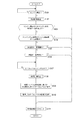
以下、上記により概要を説明した実施の形態としてのオイルレベル検出手法を実現するための具体的な処理の手順を図5のフローチャートを参照して説明する。
なお、図5に示す処理は、エンジン制御部3におけるCPUが前述したROM等の所定の記憶装置に記憶されたプログラムに基づき実行するものである。
<3. Processing procedure>
Hereinafter, a specific processing procedure for realizing the oil level detection method as the embodiment whose outline has been described above will be described with reference to the flowchart of FIG. 5.
The process shown in FIG. 5 is executed by the CPU in the
先ず、エンジン制御部3は、ステップS101でエンジンの停止が検知されるまで待機し、エンジンの停止が検知された場合はステップS102で時間計測を開始する。なお、エンジン停止の検知は、エンジン停止操作の検知であってもよいし、該停止操作に応じてエンジン停止制御を実行したことの検知であってもよい。
First, the
続くステップS103〜S106にかけての処理は、オイルレベル検出処理を実行すべきでないとして予め定められた「検出除外条件」の成立有無を判定するための処理となる。 The subsequent steps S103 to S106 are processes for determining whether or not a “detection exclusion condition” that is determined in advance as the oil level detection process should not be executed.
先ず、ステップS103では、エンジン停止までのエンジン作動時間が一定時間以下であるか否かを判定し、該エンジン作動時間が一定時間以下であるとの肯定結果が得られた場合は、ステップS111に進んで時間計測値を0リセットした上でこの図に示す処理を終了する。
エンジン停止までのエンジン作動時間が例えば10秒等の極短時間である場合には、該エンジン作動中よりも前に十分な時間エンジンが作動していたか否かや、油温の状態等の影響により、エンジン停止時点での油面Seoの高さがまちまちとなる。すなわち、該エンジン作動中よりも前の状況(以下「前状況」と表記)に左右されて油面Seoの高さが安定しない。このため、上記の前状況に関わらず油面Seoの高さが安定するまでの時間を把握し、エンジン停止までのエンジン作動時間が該把握した時間以下である場合は、上記のように時間計測を停止して、オイルレベル検出処理を行わない。これにより、オイルレベル検出の精度が低下してしまうことの防止を図っている。
なお、エンジン作動時間は、エンジン制御部3がエンジンの始動から停止までの時間として計測しているものである。
First, in step S103, it is determined whether or not the engine operating time until the engine is stopped is equal to or less than a certain time. If an affirmative result is obtained that the engine operating time is equal to or less than the certain time, the process proceeds to step S111. The process shown in this figure is completed after proceeding to reset the time measurement value to zero.
If the engine operating time until the engine stops is an extremely short time such as 10 seconds, for example, whether or not the engine has been operating for a sufficient time before the engine is operating, the influence of the oil temperature condition, etc. Thus, the height of the oil level Seo varies when the engine is stopped. That is, the height of the oil level Seo is not stable depending on the situation before the engine is operating (hereinafter referred to as “previous situation”). Therefore, regardless of the previous situation, the time until the oil level Seo is stabilized is grasped, and when the engine operating time until the engine stops is less than the grasped time, the time measurement is performed as described above. And stop the oil level detection process. This prevents the oil level detection accuracy from being lowered.
The engine operation time is measured by the
ステップS103において、エンジン停止までのエンジン作動時間が一定時間以下ではないとの否定結果が得られた場合、エンジン制御部3はステップS104に進み、エンジン停止直前のエンジン回転数が一定範囲外であったか否かを判定する。エンジン停止直前のエンジン回転数が一定範囲外であったとの肯定結果が得られた場合は、ステップS111に進んで時間計測値を0リセットした上でこの図に示す処理を終了する。
エンジン停止直前のエンジン回転数が高いほど、油面Seoの高さは低くなる(オイルパン101側からエンジン側にエンジンオイルEoを供給するためのオイルポンプによるオイル持ち出し量が大きくなるため)。すなわち、エンジン停止時点からオイルレベルスイッチ10dがオンするまでの時間が長くなる。また、エンジンの種類によっては、エンジン回転数が高いほどオイルエアレーション率が高まり、エンジン停止時点からオイルレベルスイッチ10dがオンするまでの時間が短くなる虞もある。
このようにエンジン停止直前のエンジン回転数が高いか否かは、オイルレベル検出の精度に影響を与える要素となる。このため、上記のようにエンジン停止直前のエンジン回転数が一定範囲外であったか否か(例えば、所定の回転数以上であったか否か)を判定し、肯定結果が得られた場合は時間計測を停止してオイルレベル検出処理を行わない。これにより、オイルレベル検出の精度低下の防止を図っている。
If a negative result is obtained in step S103 that the engine operating time until the engine is stopped is not less than a certain time, the
The higher the engine speed immediately before the engine stops, the lower the oil level Seo (because the amount of oil taken out by the oil pump for supplying the engine oil Eo from the oil pan 101 side to the engine side increases). That is, the time from when the engine is stopped until the
Thus, whether or not the engine speed immediately before engine stop is high is an element that affects the accuracy of oil level detection. Therefore, as described above, it is determined whether or not the engine speed immediately before the engine stops is outside a certain range (for example, whether or not the engine speed is equal to or higher than a predetermined speed), and if a positive result is obtained, time measurement is performed. Stop and do not perform the oil level detection process. This prevents the oil level detection accuracy from being lowered.
なお、エンジン停止直前のエンジン回転数としては、例えば、エンジン制御部3がエンジン回転数センサ10bによる検出信号について所定周期で行っているサンプリングについて、エンジン停止が検知された時点の直前のサンプリングタイミングにサンプリングした値とすればよい。或いは、エンジン停止が検知された時点の直近における複数サンプリングタイミングでサンプリングされた値の平均値等としてもよい。
As the engine speed immediately before the engine stop, for example, sampling performed by the
ステップS104でエンジン停止直前のエンジン回転数が一定範囲外ではなかったとの否定結果が得られた場合、エンジン制御部3はステップS105に進み、加速度が一定範囲外であるか否かを判定する。具体的には、Gセンサ10gにより検出されている加速度(車両の前後方向、左右方向に作用するそれぞれの加速度)の値が一定範囲外であるか否かを判定する。加速度が一定範囲外であるとの肯定結果が得られた場合は、ステップS111に進んで時間計測値を0リセットした上でこの図に示す処理を終了する。
例えば、エンジン停止されたときに自車両が停止している路面の状況(例えば勾配等)等によっては油面Seoが水平状態から傾く。すなわち、水平状態でのオイルレベルがレベルxより低いレベルであるにも関わらずオイルレベルスイッチ10dがオンしたり、逆に水平状態でのオイルレベルがレベルxより高いレベルであるにも関わらずオイルレベルスイッチ10dがオンしない等、オイルレベル検出の精度の低下を招く。
このため、上記のように加速度が一定範囲外であるか否か(例えば、前後、左右の加速度が共に±0.1m/s2であるか否か)を判定し、肯定結果が得られた場合は時間計測を停止してオイルレベル検出処理を行わない。これにより、オイルレベル検出の精度低下の防止を図っている。
If a negative result is obtained in step S104 that the engine speed immediately before the engine is stopped is not outside the certain range, the
For example, when the engine is stopped, the oil level Seo is inclined from the horizontal state depending on the condition of the road surface on which the host vehicle is stopped (for example, the gradient). That is, the
For this reason, as described above, it was determined whether or not the acceleration was out of a certain range (for example, whether or not both the longitudinal and lateral accelerations were ± 0.1 m / s 2 ), and a positive result was obtained. In this case, the time measurement is stopped and the oil level detection process is not performed. This prevents the oil level detection accuracy from being lowered.
ステップS105で加速度が一定範囲外ではないとの否定結果が得られた場合、エンジン制御部3はステップS106に進み、油温センサ10eにより検出されている油温の値が一定範囲外であるか否かを判定する。油温が一定範囲外であるとの肯定結果が得られた場合は、ステップS111に進んで時間計測値を0リセットした上でこの図に示す処理を終了する。
エンジンオイルEoは熱膨張するため、油温が高いほど油面Seoは高くなり、オイルレベルスイッチ10dがオンするまでの時間は短くなる。また、油温が低い場合はエンジンオイルEoの動粘度が高く、エンジン内の各部に供給されたエンジンオイルEoがオイルパン101側に戻る速度が遅くなり、オイルレベルスイッチ10dがオンするまでの時間は長くなる傾向とされる。
油温が過剰に高い場合及び過剰に低い場合まで検出対象に含めようとすると、検出したい「Full」〜「Low」の各レベルごとに設定すべき時間(オイルレベルスイッチ10dがオンするまでの時間)の範囲が広範となり、正確な検出が不能となる虞がある。このため、上記のように油温の値が一定範囲外であるか否かを判定し、肯定結果が得られた場合は時間計測を停止してオイルレベル検出処理を行わない。これにより、オイルレベル検出の精度低下の防止を図っている。
If a negative result is obtained in step S105 that the acceleration is not outside the certain range, the
Since the engine oil Eo expands thermally, the higher the oil temperature, the higher the oil level Seo, and the shorter the time until the
If the oil temperature is excessively high and excessively low, it should be set for each level of “Full” to “Low” to be detected (time until the
ステップS106で否定結果が得られた場合、すなわちステップS103〜S106の全ての「検出除外条件」を満たさないと判定された場合、エンジン制御部3はステップS107に進み、オイルレベルスイッチ10dがオンとなるまで待機する。
そして、オイルレベルスイッチ10dがオンとなった場合は、ステップS108で時間計測を停止してステップS109に進み、時間・レベル対応情報I1に基づき、計測時間に応じたオイルレベルを取得する。具体的には、計測時間が「〜a秒」に該当すれば「Full」レベルを、「a+1〜b秒」に該当すれば「Mid+α」レベルを、「b+1〜c秒」に該当すれば「Mid」レベルを、「c+1〜d秒」に該当すれば「Low+α」レベルを、「d+1秒〜」に該当すれば「Low」レベルをそれぞれ取得する。
これは、計測時間に基づき、該当するオイルレベル(油面位置)を推定し、推定したオイルレベルを検出結果として得ていると換言できる。
If a negative result is obtained in step S106, that is, if it is determined that all the “detection exclusion conditions” in steps S103 to S106 are not satisfied, the
If the
In other words, the corresponding oil level (oil surface position) is estimated based on the measurement time, and the estimated oil level is obtained as a detection result.
ステップS109で該当するオイルレベルを取得すると、エンジン制御部3はステップS110で、取得したオイルレベルの情報を記憶する。すなわち、検出したオイルレベルの情報を次回のエンジン始動に合わせて運転者に提示可能とするべく、該オイルレベルの情報をエンジン制御部3による読み出しが可能な記憶装置に対して記憶する。なお、該ステップS110で情報を記憶する記憶装置としては、不揮発性の記憶装置、或いはエンジン停止中においても電力供給が継続される揮発性の記憶装置とする。
When the corresponding oil level is acquired in step S109, the
ステップS110でオイルレベルの情報を記憶すると、エンジン制御部3はステップS111で時間計測値を0リセットし、この図に示す処理を終える。
When the oil level information is stored in step S110, the
なお、上記では、ステップS102の時間計測開始処理により、オイルレベルスイッチ10dがオンされるまでの時間計測をエンジン停止に応じて即座に開始する例を挙げたが、ステップS102の時間計測開始処理は、例えば、ステップS103〜S106の判定処理の実行を待って(つまりステップS106で否定結果が得られたことに応じて)実行してもよい。この場合、時間計測にあたっての基準時点は、エンジン停止時点とは厳密には一致しないが、オイルレベルスイッチ10dがオンされるまでの時間の計測は、あくまで、エンジンが停止された時点を基準とした所定の基準時点から開始すればよく、必ずしも厳密にエンジン停止時点と一致させる必要はない。
In the above, an example is given in which the time measurement until the
また、上記では、「検出除外条件」の一つに油温の条件を挙げたが(S106)、油温と水温には相関関係があるため、油温でなく水温を代用することもできる。この際、オイルレベルの検出精度の確保のため、水温と油温との関係を把握しておき、ステップS106における「一定範囲」として水温に対応した「一定範囲」を設定してもよい。 In the above description, the oil temperature condition is cited as one of the “detection exclusion conditions” (S106). However, since the oil temperature and the water temperature have a correlation, the water temperature can be used instead of the oil temperature. At this time, in order to ensure detection accuracy of the oil level, the relationship between the water temperature and the oil temperature may be grasped, and the “constant range” corresponding to the water temperature may be set as the “constant range” in step S106.
さらに、上記では、オイルレベルの検出を自車両が停止中の状況で行うことを前提としたが、ハイブリッド車の場合は走行中においてもエンジンが停止する場合があり、このような走行中におけるエンジン停止時点を基準とした時間計測、及び計測時間に基づくオイルレベルの推定を行うことも考えられる。走行中においては、車両の加/減速、カーブ走行中等のロールの発生等により、車両の前後、左右の加速度が生じ、検出精度の低下を招く虞がある。このため、ステップS103のような加速度による検出除外条件の判定処理を設けることが有効である。 Furthermore, in the above description, it is assumed that the oil level is detected while the host vehicle is stopped. However, in the case of a hybrid vehicle, the engine may stop even during traveling. It is also conceivable to perform time measurement based on the stop time point and estimate the oil level based on the measurement time. During traveling, acceleration of the vehicle, front / rear and left / right acceleration may occur due to the occurrence of rolls during acceleration / deceleration of the vehicle, traveling on a curve, and the like, which may cause a decrease in detection accuracy. Therefore, it is effective to provide a detection exclusion condition determination process based on acceleration as in step S103.
<4.検出手法の別例>
上記では、「検出除外条件」を満たす場合には、オイルレベル検出を行わない例を挙げた。以下では、検出手法の別例として、「検出除外条件」を満たすケースにおいてもオイルレベル検出を可能とする手法について説明する。
以下では一例として、油温が「検出除外条件」を満たすケースにおいてもオイルレベル検出を可能とする手法について説明する。
<4. Another example of detection method>
In the above, an example in which the oil level is not detected when the “detection exclusion condition” is satisfied has been described. Hereinafter, as another example of the detection method, a method that enables oil level detection even in a case that satisfies the “detection exclusion condition” will be described.
Hereinafter, as an example, a method that enables oil level detection even when the oil temperature satisfies the “detection exclusion condition” will be described.
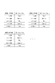
図6は、検出手法の別例で用いられる時間・レベル対応情報I2の例を示している。
図のように時間・レベル対応情報I2は、検出結果として得たい「Full」「Mid+α」「Mid」「Low+α」「Low」の各レベルと、エンジン停止時点からオイルレベルスイッチ10dがオンするまでの時間の情報との対応関係を、油温ごとに定義した情報とされている。このような時間・レベル対応情報I2は、先の図4に示した時間・レベル対応情報I1を油温ごとに用意した情報であるとも捉えることができる。時間・レベル対応情報I2の作成にあたっては、油温ごとの各レベルと時間との対応関係を予め実験等により把握しておく。
図6では、各レベルと時間との対応関係を20℃ごとに定義した例を示している。この場合、時間・レベル対応情報I2に定義されてない油温時のオイルレベルは、時間・レベル対応情報I2に定義された情報を用いて推定してもよい。一例として、時間・レベル対応情報I2に非定義の油温=15℃時のオイルレベルを検出する際には、時間・レベル対応情報I2に定義された油温=20℃時のオイルレベルごとの時間の情報を15℃と20℃の温度差に応じてそれぞれ補正し、該補正した時間の情報を基に、計測時間に該当するオイルレベルの情報を取得する。
なお、勿論、時間・レベル対応情報I2としては油温の1℃ごとに時間とレベルとの対応関係情報を用意してもよく、その場合には上記のような定義情報からの推定は不要とできる。
FIG. 6 shows an example of the time / level correspondence information I2 used in another example of the detection method.
As shown in the figure, the time / level correspondence information I2 includes the “Full”, “Mid + α”, “Mid”, “Low + α”, and “Low” levels to be obtained as detection results, and the time from when the engine stops until the
FIG. 6 shows an example in which the correspondence between each level and time is defined every 20 ° C. In this case, the oil level at the oil temperature that is not defined in the time / level correspondence information I2 may be estimated using information defined in the time / level correspondence information I2. As an example, when detecting the oil level when the oil temperature not defined in the time / level correspondence information I2 = 15 ° C., the oil temperature defined in the time / level correspondence information I2 = The time information is corrected according to the temperature difference between 15 ° C. and 20 ° C., and the oil level information corresponding to the measurement time is acquired based on the corrected time information.
Of course, as the time / level correspondence information I2, information on correspondence between time and level may be prepared for each 1 ° C. of the oil temperature, and in that case, estimation from the definition information as described above is unnecessary. it can.
なお、上記のような時間・レベル対応情報I2は、次のような情報であるとも換言できる。すなわち、エンジン停止時点からオイルレベルスイッチ10dがオンするまでの時間と油温との組み合わせに対するエンジンオイルEoのオイルレベル(油面位置)の対応関係を表した情報、である。
In addition, it can be said that the time / level correspondence information I2 as described above is the following information. That is, the information represents the correspondence relationship between the oil level (oil level position) of the engine oil Eo with respect to the combination of the time from when the engine is stopped to when the
図7のフローチャートは、検出手法の別例において実行すべき具体的な処理の手順を示している。なお、図7において、既にこれまでで説明済みとなった処理と同様の処理については同一のステップ番号を付して説明を省略する。
この場合は、ステップS106の処理は省略され、エンジン制御部3はステップS108で時間計測を停止したことに応じて、ステップS201の油温取得処理として、油温センサ10eにより検出されている油温の情報を取得する処理を行う。
その上で、エンジン制御部3はステップS202で、油温に応じて選択した時間・レベル対応情報I1に基づき、計測時間に応じたオイルレベルを取得する。
The flowchart in FIG. 7 shows a specific processing procedure to be executed in another example of the detection method. In FIG. 7, processes similar to those already described so far are denoted by the same step numbers and description thereof is omitted.
In this case, the process of step S106 is omitted, and the
Then, in step S202, the
この場合もエンジン制御部3は、オイルレベルを取得した後は、ステップS110のオイルレベル記憶処理、次いでステップS111の時間計測値0リセット処理を実行し、オイルレベル検出処理を終える。
Also in this case, after acquiring the oil level, the
なお、油温以外の他の「検出除外条件」要素についても、同様の処理を行うことができる。具体的には、エンジン停止までのエンジン作動時間、エンジン停止直前のエンジン回転数、加速度のそれぞれの要素についても、同様に各要素の値ごとに時間・レベル対応情報I1を用意しておき、オイルレベル検出時には、該当する要素の値に合致する時間・レベル対応情報I1を選択し、該選択した時間・レベル対応情報I1に基づき、計測時間に応じたオイルレベルを取得すればよい。 The same processing can be performed for the “detection exclusion condition” elements other than the oil temperature. Specifically, the time / level correspondence information I1 is similarly prepared for each element value of the engine operating time until the engine is stopped, the engine speed immediately before the engine is stopped, and the acceleration. At the time of level detection, the time / level correspondence information I1 that matches the value of the corresponding element is selected, and the oil level corresponding to the measurement time may be acquired based on the selected time / level correspondence information I1.
また、エンジン停止までのエンジン作動時間、エンジン停止直前のエンジン回転数、加速度、及び油温の全ての要素を考慮して、オイルレベル検出を行うこともできる。その場合には、これら各要素の値の組み合わせごとに(つまりエンジン作動時間=××秒、エンジン回転数=△△rpm、加速度=○○m/s2、油温=□□℃の組み合わせごとに)、エンジン停止時点からオイルレベルスイッチ10dがオンするまでの時間とオイルレベルとの対応関係を把握しておき、該対応関係を定義した時間・レベル対応情報を用いて計測時間に基づくオイルレベルの推定(検出)を行えばよい。
In addition, the oil level can be detected in consideration of all factors of the engine operating time until the engine is stopped, the engine speed immediately before the engine is stopped, the acceleration, and the oil temperature. In that case, for each combination of values of these elements (that is, for each combination of engine operating time = xx seconds, engine speed = ΔΔ rpm, acceleration = OO m / s 2 , oil temperature = □□ ° C.) B), the correspondence between the oil level and the time from when the engine stops until the
ここで、上記の「検出手法の別例」も含めこれまでの説明では、計測時間に基づくオイルレベルの推定に用いる「時間・レベル対応情報」として、テーブル情報を用いる場合を例示したが、オイルレベルの推定は、エンジン停止時点を基準とした基準時点からオイルレベルスイッチがオンするまでの時間とオイルレベルとの対応関係を表した関数に基づき行うこともできる。
このような関数としての時間・レベル対応情報を用いることで、オイルレベルの検出値は上記した「Full」〜「Low」などの段階的な値ではなく、リニアな値として求めることができる。
Here, including the above “another example of the detection method”, the description so far has exemplified the case where table information is used as the “time / level correspondence information” used for estimating the oil level based on the measurement time. The estimation of the level can also be performed based on a function representing a correspondence relationship between the oil level and the time from the reference time point when the engine is stopped as a reference until the oil level switch is turned on.
By using the time / level correspondence information as such a function, the detected value of the oil level can be obtained as a linear value instead of a stepwise value such as “Full” to “Low”.
なお、上記の「検出手法の別例」においては、このような関数としては、「検出除外条件」要素として例示したエンジン停止までのエンジン作動時間、エンジン停止直前のエンジン回転数、加速度、又は油温のうち少なくとも一つの要素、換言すれば、オイルレベルスイッチ10dがオンするまでの時間とオイルレベルとの対応関係を変化させる要素のうち少なくとも一つの要素を加味した関数を用意しておく。つまり、例えば油温の要素であれば、オイルレベルスイッチ10dがオンするまでの時間と油温との組み合わせに対するエンジンオイルEoのオイルレベルの対応関係を表した関数を用意しておく。具体的には、例えばオイルレベルスイッチ10dがオンするまでの時間と油温とを変数としてオイルレベルが求まるように生成された関数である。
このような「検出手法の別例」で用いる関数(及び時間・レベル対応情報I2として例示したようなテーブル情報)は、以下のような情報であると表現することができる。すなわち、エンジン停止時点からオイルレベルスイッチ10dがオンするまでの時間と、エンジン停止までのエンジン作動時間、エンジン停止直前のエンジン回転数、加速度、又は油温の少なくとも何れかとの組み合わせに対するエンジンオイルEoのオイルレベルの対応関係を表した情報、である。
In the above “another example of the detection method”, such functions include the engine operation time until the engine stop exemplified as the “detection exclusion condition” element, the engine speed immediately before the engine stop, the acceleration, or the oil A function is prepared in consideration of at least one element of the temperature, in other words, at least one element among the elements that change the correspondence relationship between the oil level and the time until the
The function (and the table information exemplified as the time / level correspondence information I2) used in such “another example of the detection method” can be expressed as the following information. That is, the engine oil Eo with respect to a combination of the time from when the engine is stopped until the
<5.実施の形態のまとめ>
上記のように実施の形態のエンジンオイルのレベル検出装置は、エンジンオイル(Eo)をエンジンとの間で循環可能に貯留するオイル貯留槽(オイルパン101)におけるエンジンオイルの油面位置を検出するエンジンオイルのレベル検出装置であって、油面位置が所定レベル(レベルx)に達したことに応じてオンされるオイルレベルスイッチ(10d)と、エンジンが停止された時点を基準とした基準時点からオイルレベルスイッチがオンするまでの時間を計測し、計測した時間に基づき油面位置を推定するオイルレベル推定部(エンジン制御部3)とを備えている。
<5. Summary of Embodiment>
As described above, the engine oil level detection device of the embodiment detects the oil level position of the engine oil in the oil storage tank (oil pan 101) that stores the engine oil (Eo) so as to be able to circulate with the engine. An engine oil level detection device, an oil level switch (10d) that is turned on in response to the oil level position reaching a predetermined level (level x), and a reference time point based on when the engine is stopped And an oil level estimation unit (engine control unit 3) for measuring the time from when the oil level switch is turned on to estimating the oil level position based on the measured time.
これにより、エンジンオイル油面位置の多値検出にあたり複数のオイルレベルスイッチを設ける必要がない。
従って、オイル貯留槽におけるエンジンオイルの油面位置を多値検出するエンジンオイルのレベル検出装置について、コスト削減を図ることができる。
Thereby, it is not necessary to provide a plurality of oil level switches for multi-value detection of the engine oil oil level position.
Therefore, it is possible to reduce the cost of the engine oil level detection device that multi-detects the oil level of the engine oil in the oil storage tank.
また、実施の形態のエンジンオイルのレベル検出装置においては、オイルレベル推定部は、基準時点からオイルレベルスイッチがオンするまでの時間と油面位置との対応関係を表す時間・油面位置対応情報(時間・レベル対応情報I1又はI2)に基づき油面位置を推定している。
上記のような時間と油面位置との対応関係を表す時間・油面位置対応情報を用いることで、エンジンオイル油面位置の推定を比較的簡易に行うことが可能である。具体的に、例えば時間・油面位置対応情報として前述のようなテーブル情報を用いれば、油面位置の推定にあたり計算処理を不要とすることが可能であり、また、前述した関数を用いる場合には該関数に計測時間を代入することで油面位置を簡易に推定可能である。
従って、エンジンオイルの油面位置検出に要する処理負担の軽減を図ることができる。
Further, in the engine oil level detection device according to the embodiment, the oil level estimation unit includes time / oil level position correspondence information representing a correspondence relationship between the time from the reference time point until the oil level switch is turned on and the oil level position. The oil level position is estimated based on (time / level correspondence information I1 or I2).
By using the time / oil surface position correspondence information representing the correspondence between the time and the oil surface position as described above, it is possible to estimate the engine oil oil surface position relatively easily. Specifically, for example, if the table information as described above is used as the time / oil level position correspondence information, it is possible to eliminate the calculation process in estimating the oil level position. The oil level position can be easily estimated by substituting the measurement time into the function.
Therefore, it is possible to reduce the processing load required for detecting the oil level of the engine oil.
さらに、実施の形態のエンジンオイルのレベル検出装置においては、オイルレベル推定部は、基準時点からオイルレベルスイッチがオンするまでの時間として想定される各時間ごとに油面位置の情報が対応づけられたテーブル情報としての時間・油面位置対応情報に基づき油面位置を推定している。
これにより、エンジンオイル油面位置の推定は、上記のテーブル情報から計測時間に対応するエンジンオイルの油面位置情報を取得するのみで実現される。
従って、エンジンオイルの油面位置検出に要する処理負担の軽減を図ることができる。
Further, in the engine oil level detection device according to the embodiment, the oil level estimation unit associates the oil level position information with each time assumed as the time from the reference time point until the oil level switch is turned on. The oil level position is estimated based on time / oil level position correspondence information as table information.
Thereby, the estimation of the engine oil oil level position is realized only by acquiring the oil level position information of the engine oil corresponding to the measurement time from the table information.
Therefore, it is possible to reduce the processing load required for detecting the oil level of the engine oil.
また、実施の形態のエンジンオイルのレベル検出装置においては、オイルレベル推定部は、エンジンの停止までの作動時間、エンジンの停止の直前における回転数、オイル貯留槽が設けられた車両に作用している加速度、又はエンジンオイルの温度の少なくとも何れかが予め定められた想定値を逸脱しているか否かを判定し、想定値を逸脱している場合は油面位置の推定を行わないようにしている。
エンジンの停止までの作動時間、エンジンの停止直前における回転数、オイル貯留槽が設けられた車両に作用している加速度、又はエンジンオイルの温度は、基準時点からオイルレベルスイッチがオンするまでの時間とエンジンオイル油面位置との対応関係を変化させる要素であり、これらの要素が想定値を逸脱している場合に油面位置の推定を行わないことで、エンジンオイル油面位置の検出精度の低下防止を図ることができる。
In the engine oil level detection device according to the embodiment, the oil level estimation unit acts on the vehicle provided with the operating time until the engine stops, the rotation speed immediately before the engine stops, and the oil storage tank. It is determined whether or not at least one of the acceleration and the temperature of the engine oil deviates from a predetermined assumed value, and if it deviates from the assumed value, the oil level position is not estimated. Yes.
The operating time until the engine stops, the number of revolutions immediately before the engine stops, the acceleration acting on the vehicle provided with the oil storage tank, or the temperature of the engine oil is the time from the reference time until the oil level switch is turned on. The engine oil level position detection accuracy is improved by not estimating the oil level position when these factors deviate from the assumed values. Reduction can be prevented.
さらに、実施の形態のエンジンオイルのレベル検出装置においては、オイルレベル推定部は、基準時点からオイルレベルスイッチがオンするまでの時間と、エンジンの停止までの作動時間、エンジンの停止の直前における回転数、オイル貯留槽が設けられた車両に作用している加速度、又はエンジンオイルの温度の少なくとも何れかとの組み合わせに対する油面位置の対応関係を表した時間・油面位置対応情報に基づき、油面位置を推定している。
これにより、基準時点からオイルレベルスイッチがオンするまでの時間に基づくエンジンオイル油面位置の推定が、当該基準時点からオイルレベルスイッチがオンするまでの時間とエンジンオイル油面位置との対応関係を変化させる要素を加味した形で行われる。
従って、エンジンオイル油面位置の検出精度の向上を図ることができる。
Furthermore, in the engine oil level detection device of the embodiment, the oil level estimation unit includes the time from the reference time until the oil level switch is turned on, the operation time until the engine is stopped, and the rotation immediately before the engine is stopped. The oil level is based on the time / oil level position correspondence information indicating the relationship of the oil level position to the combination of the number, the acceleration acting on the vehicle provided with the oil storage tank, and / or the temperature of the engine oil. Estimating the position.
As a result, the estimation of the engine oil oil level position based on the time from the reference time point until the oil level switch is turned on indicates the correspondence between the time from the reference time point until the oil level switch is turned on and the engine oil oil level position. It is done in a form that takes into account the changing elements.
Therefore, it is possible to improve the detection accuracy of the engine oil oil level position.
<6.変形例>
以上、本発明の実施の形態について説明したが、本発明は上記で説明した具体例に限定されず、多様な変形例が考えられる。
例えば、上記では、本発明に係る処理の実行主体がエンジン制御部3とされた場合を例示したが、本発明に係る処理のうち少なくとも一部をエンジン制御部3以外の他の制御部(ECU:Electronic Control Unit)が担うなど、処理の実行主体は上記の例に限定されない。
<6. Modification>
Although the embodiments of the present invention have been described above, the present invention is not limited to the specific examples described above, and various modifications can be considered.
For example, in the above, the case where the execution subject of the process according to the present invention is the
また、上記では、本発明が車両に適用された場合を例示したが、本発明はエンジンを搭載した乗用物等の物体に広く適用可能なものである。 Moreover, although the case where this invention was applied to the vehicle was illustrated above, this invention is widely applicable to objects, such as a vehicle mounted with an engine.
1…車両制御装置、3…エンジン制御部、10b…エンジン回転数センサ、10d…オイルレベルスイッチ、10e…油温センサ、10f…水温センサ、101…オイルパン、Eo…エンジンオイル、Seo…油面
DESCRIPTION OF
Claims (5)
前記油面位置が所定レベルに達したことに応じてオンされるオイルレベルスイッチと、
前記エンジンが停止された時点を基準とした基準時点から前記オイルレベルスイッチがオンするまでの時間を計測し、計測した前記時間に基づき前記油面位置を推定するオイルレベル推定部と、を備える
エンジンオイルのレベル検出装置。 An engine oil level detection device that detects an oil level position of the engine oil in an oil storage tank that circulates engine oil between the engine oil,
An oil level switch that is turned on in response to the oil level position reaching a predetermined level;
An oil level estimating unit that measures a time from a reference time point when the engine is stopped to a time when the oil level switch is turned on, and estimates the oil level position based on the measured time. Oil level detection device.
前記基準時点からオイルレベルスイッチがオンするまでの時間と前記油面位置との対応関係を表す時間・油面位置対応情報に基づき前記油面位置を推定する
請求項1に記載のエンジンオイルのレベル検出装置。 The oil level estimator is
2. The engine oil level according to claim 1, wherein the oil level position is estimated based on time / oil level position correspondence information representing a correspondence relationship between a time from the reference time point until the oil level switch is turned on and the oil level position. Detection device.
前記基準時点から前記オイルレベルスイッチがオンするまでの時間として想定される各時間ごとに前記油面位置の情報が対応づけられたテーブル情報としての前記時間・油面位置対応情報に基づき前記油面位置を推定する
請求項2に記載のエンジンオイルのレベル検出装置。 The oil level estimator is
The oil level based on the time-oil level position correspondence information as table information in which the information on the oil level position is associated with each time assumed as the time from the reference time point until the oil level switch is turned on. The engine oil level detection device according to claim 2, wherein the position is estimated.
前記エンジンの前記停止までの作動時間、前記エンジンの前記停止の直前における回転数、前記オイル貯留槽が設けられた車両に作用している加速度、又は前記エンジンオイルの温度の少なくとも何れかが予め定められた想定値を逸脱しているか否かを判定し、前記想定値を逸脱している場合は前記油面位置の推定を行わない
請求項1乃至請求項3何れかに記載のエンジンオイルのレベル検出装置。 The oil level estimator is
At least one of an operation time until the engine is stopped, a rotational speed immediately before the engine is stopped, an acceleration acting on a vehicle provided with the oil storage tank, and a temperature of the engine oil is determined in advance. The engine oil level according to any one of claims 1 to 3, wherein it is determined whether or not the estimated value is deviated, and the oil level position is not estimated when deviating from the assumed value. Detection device.
前記基準時点から前記オイルレベルスイッチがオンするまでの時間と、前記エンジンの前記停止までの作動時間、前記エンジンの前記停止の直前における回転数、前記オイル貯留槽が設けられた車両に作用している加速度、又は前記エンジンオイルの温度の少なくとも何れかとの組み合わせに対する前記油面位置の対応関係を表した前記時間・油面位置対応情報に基づき、前記油面位置を推定する
請求項1乃至請求項3何れかに記載のエンジンオイルのレベル検出装置。 The oil level estimator is
The time until the oil level switch is turned on from the reference time point, the operation time until the engine is stopped, the rotational speed immediately before the engine is stopped, and the vehicle provided with the oil storage tank The oil level position is estimated based on the time / oil level position correspondence information representing a correspondence relationship of the oil level position to a combination of at least one of acceleration and / or engine oil temperature. 3. The engine oil level detection device according to any one of 3 above.
Priority Applications (1)
| Application Number | Priority Date | Filing Date | Title |
|---|---|---|---|
| JP2015032137A JP6374331B2 (en) | 2015-02-20 | 2015-02-20 | Engine oil level detector |
Applications Claiming Priority (1)
| Application Number | Priority Date | Filing Date | Title |
|---|---|---|---|
| JP2015032137A JP6374331B2 (en) | 2015-02-20 | 2015-02-20 | Engine oil level detector |
Publications (3)
| Publication Number | Publication Date |
|---|---|
| JP2016153627A JP2016153627A (en) | 2016-08-25 |
| JP2016153627A5 JP2016153627A5 (en) | 2017-12-28 |
| JP6374331B2 true JP6374331B2 (en) | 2018-08-15 |
Family
ID=56760473
Family Applications (1)
| Application Number | Title | Priority Date | Filing Date |
|---|---|---|---|
| JP2015032137A Active JP6374331B2 (en) | 2015-02-20 | 2015-02-20 | Engine oil level detector |
Country Status (1)
| Country | Link |
|---|---|
| JP (1) | JP6374331B2 (en) |
Families Citing this family (3)
| Publication number | Priority date | Publication date | Assignee | Title |
|---|---|---|---|---|
| JP7091661B2 (en) * | 2018-01-09 | 2022-06-28 | いすゞ自動車株式会社 | Oil level estimator |
| JP2020153319A (en) * | 2019-03-20 | 2020-09-24 | いすゞ自動車株式会社 | Engine oil amount estimation device and engine oil amount estimation method |
| JP7276220B2 (en) * | 2020-03-24 | 2023-05-18 | いすゞ自動車株式会社 | Oil level detection device and vehicle |
Family Cites Families (6)
| Publication number | Priority date | Publication date | Assignee | Title |
|---|---|---|---|---|
| JPS5784316A (en) * | 1980-11-14 | 1982-05-26 | Honda Motor Co Ltd | Device for displaying engine oil level for automobile |
| JPH0613849B2 (en) * | 1985-12-17 | 1994-02-23 | 本田技研工業株式会社 | Engine oil level detection method |
| JPH0334672Y2 (en) * | 1987-07-22 | 1991-07-23 | ||
| JPH05332120A (en) * | 1992-06-04 | 1993-12-14 | Mitsubishi Motors Corp | Engine oil level display control device |
| JP4825156B2 (en) * | 2007-03-13 | 2011-11-30 | 大阪瓦斯株式会社 | Engine oil condition monitoring device |
| JP6003805B2 (en) * | 2013-05-23 | 2016-10-05 | マツダ株式会社 | Engine oil level detector |
-
2015
- 2015-02-20 JP JP2015032137A patent/JP6374331B2/en active Active
Also Published As
| Publication number | Publication date |
|---|---|
| JP2016153627A (en) | 2016-08-25 |
Similar Documents
| Publication | Publication Date | Title |
|---|---|---|
| KR101525637B1 (en) | Method for controlling a solenoid valve and apparatus for carrying out said method | |
| JP6374331B2 (en) | Engine oil level detector | |
| US8145398B2 (en) | Method for controlling gear ratio changes in an automatic transmission | |
| JP6475098B2 (en) | Engine oil level detector | |
| CN105517861B (en) | Ramp rollback speed control | |
| KR101646113B1 (en) | Method of road slope estimating and shift control device thereof | |
| CN102046945A (en) | Engine control device | |
| KR101518918B1 (en) | Apparatus and method for displaying available driving distance of vehicle | |
| CN102365195A (en) | Vehicle travel control device | |
| KR20160146730A (en) | Ascertaining an offset of an inertial sensor | |
| CN104691552A (en) | System and method of controlling starting of Vehicle | |
| JP5237599B2 (en) | vehicle | |
| JP5097165B2 (en) | Vehicle control device | |
| CN114375269A (en) | Apparatus and method for estimating road friction coefficient | |
| JP5990991B2 (en) | Vehicle control device | |
| JP2007127155A (en) | Starting auxiliary device | |
| JP4622729B2 (en) | Body speed calculation device | |
| US10723357B2 (en) | Traction control system and control method thereof | |
| US20210062913A1 (en) | Speed change control apparatus for automatic transmission | |
| US20210086625A1 (en) | Controller and method of controlling speed of a vehicle | |
| CN112721920A (en) | Low-speed control method and system for automatic parking of vehicle, vehicle and storage medium | |
| JP2010070142A (en) | Road surface friction coefficient estimation device and anti-skid control | |
| JP4534840B2 (en) | Brake control device | |
| JP2007278982A (en) | Vehicle behavior controller | |
| JP6540163B2 (en) | Road slope estimation device and road slope estimation method |
Legal Events
| Date | Code | Title | Description |
|---|---|---|---|
| A521 | Request for written amendment filed |
Free format text: JAPANESE INTERMEDIATE CODE: A523 Effective date: 20171116 |
|
| A621 | Written request for application examination |
Free format text: JAPANESE INTERMEDIATE CODE: A621 Effective date: 20171116 |
|
| TRDD | Decision of grant or rejection written | ||
| A977 | Report on retrieval |
Free format text: JAPANESE INTERMEDIATE CODE: A971007 Effective date: 20180614 |
|
| A01 | Written decision to grant a patent or to grant a registration (utility model) |
Free format text: JAPANESE INTERMEDIATE CODE: A01 Effective date: 20180626 |
|
| A61 | First payment of annual fees (during grant procedure) |
Free format text: JAPANESE INTERMEDIATE CODE: A61 Effective date: 20180719 |
|
| R150 | Certificate of patent or registration of utility model |
Ref document number: 6374331 Country of ref document: JP Free format text: JAPANESE INTERMEDIATE CODE: R150 |
|
| R250 | Receipt of annual fees |
Free format text: JAPANESE INTERMEDIATE CODE: R250 |
|
| R250 | Receipt of annual fees |
Free format text: JAPANESE INTERMEDIATE CODE: R250 |
|
| R250 | Receipt of annual fees |
Free format text: JAPANESE INTERMEDIATE CODE: R250 |