JP6373859B2 - Oral circular anvil introduction system with expanded features - Google Patents
Oral circular anvil introduction system with expanded features Download PDFInfo
- Publication number
- JP6373859B2 JP6373859B2 JP2015545817A JP2015545817A JP6373859B2 JP 6373859 B2 JP6373859 B2 JP 6373859B2 JP 2015545817 A JP2015545817 A JP 2015545817A JP 2015545817 A JP2015545817 A JP 2015545817A JP 6373859 B2 JP6373859 B2 JP 6373859B2
- Authority
- JP
- Japan
- Prior art keywords
- anvil
- feature
- introduction system
- trocar
- shaft
- Prior art date
- Legal status (The legal status is an assumption and is not a legal conclusion. Google has not performed a legal analysis and makes no representation as to the accuracy of the status listed.)
- Expired - Fee Related
Links
- 239000012530 fluid Substances 0.000 claims description 9
- 230000004044 response Effects 0.000 claims description 8
- 230000007704 transition Effects 0.000 claims description 4
- 238000013519 translation Methods 0.000 claims description 4
- FAPWRFPIFSIZLT-UHFFFAOYSA-M Sodium chloride Chemical compound [Na+].[Cl-] FAPWRFPIFSIZLT-UHFFFAOYSA-M 0.000 claims description 2
- 210000003238 esophagus Anatomy 0.000 description 22
- 238000000034 method Methods 0.000 description 20
- 230000007246 mechanism Effects 0.000 description 17
- 238000005516 engineering process Methods 0.000 description 12
- 230000003872 anastomosis Effects 0.000 description 9
- 239000000463 material Substances 0.000 description 8
- 238000003780 insertion Methods 0.000 description 5
- 230000037431 insertion Effects 0.000 description 5
- 238000001356 surgical procedure Methods 0.000 description 5
- 230000008878 coupling Effects 0.000 description 4
- 238000010168 coupling process Methods 0.000 description 4
- 238000005859 coupling reaction Methods 0.000 description 4
- 230000004048 modification Effects 0.000 description 4
- 238000012986 modification Methods 0.000 description 4
- 230000005855 radiation Effects 0.000 description 4
- 230000003874 surgical anastomosis Effects 0.000 description 4
- 238000004140 cleaning Methods 0.000 description 3
- 210000001035 gastrointestinal tract Anatomy 0.000 description 3
- 230000014509 gene expression Effects 0.000 description 3
- 230000033001 locomotion Effects 0.000 description 3
- 239000000853 adhesive Substances 0.000 description 2
- 230000001070 adhesive effect Effects 0.000 description 2
- 238000005452 bending Methods 0.000 description 2
- 238000010304 firing Methods 0.000 description 2
- 241000894006 Bacteria Species 0.000 description 1
- IAYPIBMASNFSPL-UHFFFAOYSA-N Ethylene oxide Chemical compound C1CO1 IAYPIBMASNFSPL-UHFFFAOYSA-N 0.000 description 1
- 239000004775 Tyvek Substances 0.000 description 1
- 229920000690 Tyvek Polymers 0.000 description 1
- 230000009471 action Effects 0.000 description 1
- 238000013459 approach Methods 0.000 description 1
- 230000008901 benefit Effects 0.000 description 1
- 230000005540 biological transmission Effects 0.000 description 1
- 230000006835 compression Effects 0.000 description 1
- 238000007906 compression Methods 0.000 description 1
- 238000010276 construction Methods 0.000 description 1
- 238000011443 conventional therapy Methods 0.000 description 1
- 230000007423 decrease Effects 0.000 description 1
- 239000012636 effector Substances 0.000 description 1
- 230000000694 effects Effects 0.000 description 1
- 208000015181 infectious disease Diseases 0.000 description 1
- 230000003993 interaction Effects 0.000 description 1
- 239000012528 membrane Substances 0.000 description 1
- HLXZNVUGXRDIFK-UHFFFAOYSA-N nickel titanium Chemical compound [Ti].[Ti].[Ti].[Ti].[Ti].[Ti].[Ti].[Ti].[Ti].[Ti].[Ti].[Ni].[Ni].[Ni].[Ni].[Ni].[Ni].[Ni].[Ni].[Ni].[Ni].[Ni].[Ni].[Ni].[Ni] HLXZNVUGXRDIFK-UHFFFAOYSA-N 0.000 description 1
- 229910001000 nickel titanium Inorganic materials 0.000 description 1
- 230000002093 peripheral effect Effects 0.000 description 1
- 230000008569 process Effects 0.000 description 1
- 239000012266 salt solution Substances 0.000 description 1
- 238000010008 shearing Methods 0.000 description 1
- 239000011780 sodium chloride Substances 0.000 description 1
- 230000001954 sterilising effect Effects 0.000 description 1
- 238000004659 sterilization and disinfection Methods 0.000 description 1
- 210000002784 stomach Anatomy 0.000 description 1
- 238000002560 therapeutic procedure Methods 0.000 description 1
- 238000002604 ultrasonography Methods 0.000 description 1
- 210000001835 viscera Anatomy 0.000 description 1
- XLYOFNOQVPJJNP-UHFFFAOYSA-N water Chemical compound O XLYOFNOQVPJJNP-UHFFFAOYSA-N 0.000 description 1
Images


Classifications
-
- A—HUMAN NECESSITIES
- A61—MEDICAL OR VETERINARY SCIENCE; HYGIENE
- A61B—DIAGNOSIS; SURGERY; IDENTIFICATION
- A61B17/00—Surgical instruments, devices or methods, e.g. tourniquets
- A61B17/11—Surgical instruments, devices or methods, e.g. tourniquets for performing anastomosis; Buttons for anastomosis
- A61B17/1114—Surgical instruments, devices or methods, e.g. tourniquets for performing anastomosis; Buttons for anastomosis of the digestive tract, e.g. bowels or oesophagus
-
- A—HUMAN NECESSITIES
- A61—MEDICAL OR VETERINARY SCIENCE; HYGIENE
- A61B—DIAGNOSIS; SURGERY; IDENTIFICATION
- A61B17/00—Surgical instruments, devices or methods, e.g. tourniquets
- A61B17/068—Surgical staplers, e.g. containing multiple staples or clamps
-
- A—HUMAN NECESSITIES
- A61—MEDICAL OR VETERINARY SCIENCE; HYGIENE
- A61B—DIAGNOSIS; SURGERY; IDENTIFICATION
- A61B17/00—Surgical instruments, devices or methods, e.g. tourniquets
- A61B17/11—Surgical instruments, devices or methods, e.g. tourniquets for performing anastomosis; Buttons for anastomosis
- A61B17/115—Staplers for performing anastomosis in a single operation
- A61B17/1155—Circular staplers comprising a plurality of staples
-
- A—HUMAN NECESSITIES
- A61—MEDICAL OR VETERINARY SCIENCE; HYGIENE
- A61B—DIAGNOSIS; SURGERY; IDENTIFICATION
- A61B17/00—Surgical instruments, devices or methods, e.g. tourniquets
- A61B17/00234—Surgical instruments, devices or methods, e.g. tourniquets for minimally invasive surgery
- A61B2017/00238—Type of minimally invasive operation
- A61B2017/00278—Transorgan operations, e.g. transgastric
-
- A—HUMAN NECESSITIES
- A61—MEDICAL OR VETERINARY SCIENCE; HYGIENE
- A61B—DIAGNOSIS; SURGERY; IDENTIFICATION
- A61B17/00—Surgical instruments, devices or methods, e.g. tourniquets
- A61B2017/0046—Surgical instruments, devices or methods, e.g. tourniquets with a releasable handle; with handle and operating part separable
- A61B2017/00473—Distal part, e.g. tip or head
-
- A—HUMAN NECESSITIES
- A61—MEDICAL OR VETERINARY SCIENCE; HYGIENE
- A61B—DIAGNOSIS; SURGERY; IDENTIFICATION
- A61B17/00—Surgical instruments, devices or methods, e.g. tourniquets
- A61B2017/00535—Surgical instruments, devices or methods, e.g. tourniquets pneumatically or hydraulically operated
- A61B2017/00557—Surgical instruments, devices or methods, e.g. tourniquets pneumatically or hydraulically operated inflatable
-
- A—HUMAN NECESSITIES
- A61—MEDICAL OR VETERINARY SCIENCE; HYGIENE
- A61B—DIAGNOSIS; SURGERY; IDENTIFICATION
- A61B17/00—Surgical instruments, devices or methods, e.g. tourniquets
- A61B2017/00743—Type of operation; Specification of treatment sites
- A61B2017/00818—Treatment of the gastro-intestinal system
-
- A—HUMAN NECESSITIES
- A61—MEDICAL OR VETERINARY SCIENCE; HYGIENE
- A61B—DIAGNOSIS; SURGERY; IDENTIFICATION
- A61B17/00—Surgical instruments, devices or methods, e.g. tourniquets
- A61B17/068—Surgical staplers, e.g. containing multiple staples or clamps
- A61B17/072—Surgical staplers, e.g. containing multiple staples or clamps for applying a row of staples in a single action, e.g. the staples being applied simultaneously
- A61B2017/07214—Stapler heads
- A61B2017/0725—Stapler heads with settable gap between anvil and cartridge, e.g. for different staple heights at different shots
-
- A—HUMAN NECESSITIES
- A61—MEDICAL OR VETERINARY SCIENCE; HYGIENE
- A61B—DIAGNOSIS; SURGERY; IDENTIFICATION
- A61B17/00—Surgical instruments, devices or methods, e.g. tourniquets
- A61B17/11—Surgical instruments, devices or methods, e.g. tourniquets for performing anastomosis; Buttons for anastomosis
- A61B2017/1132—End-to-end connections
-
- A—HUMAN NECESSITIES
- A61—MEDICAL OR VETERINARY SCIENCE; HYGIENE
- A61B—DIAGNOSIS; SURGERY; IDENTIFICATION
- A61B17/00—Surgical instruments, devices or methods, e.g. tourniquets
- A61B17/11—Surgical instruments, devices or methods, e.g. tourniquets for performing anastomosis; Buttons for anastomosis
- A61B2017/1142—Purse-string sutures
-
- A—HUMAN NECESSITIES
- A61—MEDICAL OR VETERINARY SCIENCE; HYGIENE
- A61B—DIAGNOSIS; SURGERY; IDENTIFICATION
- A61B17/00—Surgical instruments, devices or methods, e.g. tourniquets
- A61B17/11—Surgical instruments, devices or methods, e.g. tourniquets for performing anastomosis; Buttons for anastomosis
- A61B17/115—Staplers for performing anastomosis in a single operation
- A61B2017/1157—Staplers for performing anastomosis in a single operation applying the staples radially
-
- A—HUMAN NECESSITIES
- A61—MEDICAL OR VETERINARY SCIENCE; HYGIENE
- A61B—DIAGNOSIS; SURGERY; IDENTIFICATION
- A61B90/00—Instruments, implements or accessories specially adapted for surgery or diagnosis and not covered by any of the groups A61B1/00 - A61B50/00, e.g. for luxation treatment or for protecting wound edges
- A61B90/08—Accessories or related features not otherwise provided for
- A61B2090/0801—Prevention of accidental cutting or pricking
- A61B2090/08021—Prevention of accidental cutting or pricking of the patient or his organs
-
- A—HUMAN NECESSITIES
- A61—MEDICAL OR VETERINARY SCIENCE; HYGIENE
- A61B—DIAGNOSIS; SURGERY; IDENTIFICATION
- A61B2217/00—General characteristics of surgical instruments
- A61B2217/002—Auxiliary appliance
- A61B2217/007—Auxiliary appliance with irrigation system
-
- A—HUMAN NECESSITIES
- A61—MEDICAL OR VETERINARY SCIENCE; HYGIENE
- A61B—DIAGNOSIS; SURGERY; IDENTIFICATION
- A61B34/00—Computer-aided surgery; Manipulators or robots specially adapted for use in surgery
- A61B34/30—Surgical robots
Landscapes
- Health & Medical Sciences (AREA)
- Life Sciences & Earth Sciences (AREA)
- Surgery (AREA)
- Heart & Thoracic Surgery (AREA)
- Engineering & Computer Science (AREA)
- Biomedical Technology (AREA)
- Nuclear Medicine, Radiotherapy & Molecular Imaging (AREA)
- Medical Informatics (AREA)
- Molecular Biology (AREA)
- Animal Behavior & Ethology (AREA)
- General Health & Medical Sciences (AREA)
- Public Health (AREA)
- Veterinary Medicine (AREA)
- Physiology (AREA)
- Surgical Instruments (AREA)
Description
いくつかの環境では、外科医は、患者の開口部を通して外科用器具を位置付け、この器具を使用して、患者の体内で組織を調節する、位置付ける、取付ける、及び/又は別の方法で組織との相互作用を求めることがある。例えば、いくつかの外科処置では、望ましくない組織を排除するか又は他の理由で、胃腸管の部分を切り離し除去することがある。一旦所望の組織が除去されると、残りの部分は、一緒に再連結される必要があることがある。これらの吻合処置を達成するための1つのかかる用具は、患者の開口部を通して挿入される円形ステープラーである。 In some circumstances, the surgeon positions a surgical instrument through the patient's opening and uses the instrument to adjust, position, attach, and / or otherwise interact with the tissue within the patient's body. May ask for interaction. For example, in some surgical procedures, portions of the gastrointestinal tract may be cut off and removed for the removal of unwanted tissue or for other reasons. Once the desired tissue has been removed, the remaining portions may need to be reconnected together. One such tool for accomplishing these anastomosis procedures is a circular stapler that is inserted through the patient's opening.
円形外科用ステープラーは、米国特許第5,205,459号(1993年4月27日発行の「Surgical Anastomosis Stapling Instrument」)、米国特許第5,271,544,号(1993年12月21日発行の「Surgical Anastomosis Stapling Instrument」)、米国特許第5,275,322号(1994年1月4日発行の「Surgical Anastomosis Stapling Instrument」)、米国特許第5,285,945号(1994年2月15日発行の「Surgical Anastomosis Stapling Instrument」)、米国特許第5,292,053号(1994年3月8日発行の「Surgical Anastomosis Stapling Instrument」)、米国特許第5,333,773号(1994年8月2日発行の「Surgical Anastomosis Stapling Instrument」)、米国特許第5,350,104号(1994年9月27日発行の「Surgical Anastomosis Stapling Instrument」)、及び米国特許第5,533,661号(1996年7月9日発行の「Surgical Anastomosis Stapling Instrument」)に記載されている。これらの米国特許のそれぞれの開示内容は参照により本明細書に組み込まれる。一部のそのようなステープラーは、組織の層をクランプし、組織のクランプされた層を切り開き、ステープルを組織の層を通して打ち込んで、組織の切断層を組織層の切断端部付近で一緒に実質的に密閉するように動作可能であり、それによって、解剖学的管腔の2つの切断端部を接続する。 Circular surgical staplers are disclosed in US Pat. No. 5,205,459 (“Surgical Analysis Stapling Instrument” issued April 27, 1993), US Pat. No. 5,271,544 (issued December 21, 1993). "Surgical Anastomosis Staging Instrument", U.S. Pat. No. 5,275,322 ("Surgical Anastomosis Stapling Instrument" issued Jan. 4, 1994), U.S. Pat. No. 5,285,945 (Feb. 15, 1994). “Surgical Analysis Stapling Instrument” issued in Japan, US Pat. No. 5,292,053 (“Su” issued March 8, 1994) gical Anastomosis Stapling Instrument ”), US Pat. No. 5,333,773 (“ Surgical Anastomosis Stapling Instrument ”issued August 2, 1994), US Pat. No. 5,350,104 (issued September 27, 1994) "Surnal Analyst Staging Instrument") and U.S. Pat. No. 5,533,661 ("Surgical Anastomosis Stapling Instrument" issued July 9, 1996). The disclosure of each of these US patents is incorporated herein by reference. Some such staplers clamp the tissue layer, cut open the clamped layer of tissue, drive staples through the tissue layer, and substantially cut the tissue cutting layer together near the cut end of the tissue layer. And is operable to seal, thereby connecting the two cut ends of the anatomical lumen.
更なるあくまで例示の他の外科用ステープラーは、米国特許第4,805,823号(1989年2月21日発行の「Pocket Configuration for Internal Organ Staplers」)、同第5,415,334号(1995年5月16日発行の「Surgical Stapler and Staple Cartridge」)、同第5,465,895号(1995年11月14日発行の「Surgical Stapler Instrument」)、同第5,597,107号(1997年1月28日発行の「Surgical Stapler Instrument」)、同第5,632,432号(1997年5月27日発行の「Surgical Instrument」)、同第5,673,840号(1997年10月7日発行の「Surgical Instrument」)、同第5,704,534号(1998年1月6日発行の「Articulation Assembly for Surgical Instruments」)、同第5,814,055号(1998年9月29日発行の「Surgical Clamping Mechanism」)、同第6,978,921号(2005年12月27日発行の「Surgical Stapling Instrument Incorporating an E−Beam Firing Mechanism」)、同第7,000,818号(2006年2月21日発行の「Surgical Stapling Instrument Having Separate Distinct Closing and Firing Systems」)、同第7,143,923号(2006年12月5日発行の「Surgical Stapling Instrument Having a Firing Lockout for an Unclosed Anvil」)、同第7,303,108号(2007年12月4日発行の「Surgical Stapling Instrument Incorporating a Multi−Stroke Firing Mechanism with a Flexible Rack」)、同第7,367,485号(2008年5月6日発行の「Surgical Stapling Instrument Incorporating a Multistroke Firing Mechanism Having a Rotary Transmission」)、米同第7,380,695号(2008年6月3日発行の「Surgical Stapling Instrument Having a Single Lockout Mechanism for Prevention of Firing」)、同許第7,380,696号(2008年6月3日発行の「Articulating Surgical Stapling Instrument Incorporating a Two−Piece E−Beam Firing Mechanism」)、同第7,404,508号(2008年7月29日発行の「Surgical Stapling and Cutting Device」)、同第7,434,715号、2008年10月14日発行の「Surgical Stapling Instrument Having Multistroke Firing with Opening Lockout」)、及び同第7,721,930号(2010年5月25日発行の「Disposable Cartridge with Adhesive for Use with a Stapling Device」)に開示されている。これらの米国特許のそれぞれの開示内容は参照により本明細書に組み込まれる。参考として上述した外科用ステープラーは、内視鏡手技において使用されるものとして記載されているが、かかる外科用ステープラーは、開口手技及び/又は他の非内視鏡手技でも使用することができることを理解されたい。 Still other exemplary surgical staplers are disclosed in U.S. Pat. No. 4,805,823 ("Pocket Configuration for Internal Organ Staplers", issued February 21, 1989), No. 5,415,334 (1995). “Surgical Stapler and Staple Cartridge” issued on May 16, 1995, No. 5,465,895 (“Surgical Stapler Instrument” issued on November 14, 1995), No. 5,597,107 (1997) No. 5,632,432 (“Surgical Instrument” issued on May 27, 1997), No. 5 , 673, 840 (“Surgical Instrument” published on October 7, 1997), 5,704,534 (“Articulation Assembly for Surgical Instruments” published on January 6, 1998), No. 814, 055 (“Surgical Clamping Mechanism” issued on September 29, 1998) and No. 6,978,921 (“Surgery Stapling Instrument Incorporating E-Beam Firing” issued on December 27, 2005). No. 7,000,818 ("Surgical Stapling Instrument Havin" issued February 21, 2006). g Separate Distributing Closing and Filing Systems ”, 7, 143, 923 (“ Surgery Stapling Instrument Haven Locking Fort ”, issued December 5, 2006) (Issued on December 4, 2007, “Surgery Stapling Instrument Incorporating a Multi-Stroke Filling Mechanism with a Flexible Rack”, No. 7, 367, 485, published on May 6, 2008) ng a Multistroke Filing Mechanism Haven a Rotation Transmission ”), US No. 7,380,695 (Surgical Staging Infection M , 380, 696 ("Articulating Surgical Stapling Incorporating a Two-Piece E-Beam Filling Machinery", issued June 3, 2008, No. 7, 404, 507 (2008) Surgical Sta ling and Cutting Device "), 7,434,715," Surgical Stapling Instrument Having Multi-Opening Locking Lockout ") issued on October 14, 2008, and 7, 721, 30 (in Japanese). “Disposable Cartridge with Adhesive for Use with a Stapling Device” issued on May 25. The disclosure of each of these US patents is incorporated herein by reference. Although the surgical stapler described above for reference is described as being used in an endoscopic procedure, it should be noted that such a surgical stapler can also be used in an open procedure and / or other non-endoscopic procedures. I want you to understand.
様々な種類の外科用ステープル器具及び関連構成要素が作製され使用されてきたが、本発明者ら以前には、付属の請求項に記載されている本発明を誰も作製又は使用したことがないものと考えられる。 Although various types of surgical stapling instruments and related components have been made and used, no one has made or used the invention described in the appended claims before. It is considered a thing.
本明細書は、本技術を具体的に指摘し、かつ明確にその権利を請求する、特許請求の範囲によって完結するが、本技術は、以下の特定の実施例の説明を、添付図面と併せ読むことで、より良く理解されるものと考えられ、図面では、同様の参照符号は、同じ要素を特定する。
図面は、決して限定することを意図するものではなく、本技術の様々な実施形態は、必ずしも図面に示されないものも含めた、様々な他の方法で実施し得ることが想到される。本明細書に組み込まれ、その一部を形成する添付図面は、本技術のいくつかの態様を示し、説明文と共に、本技術の原理を説明する役割を果たすものであるが、それを理解した上で、本技術は、示される厳密な配置構成に限定されるものではない。 The drawings are not intended to be limiting in any way, and it is contemplated that various embodiments of the technology may be implemented in a variety of other ways, including not necessarily shown in the drawings. The accompanying drawings, which are incorporated in and form a part of this specification, illustrate several aspects of the technology and, together with the description, serve to explain the principles of the technology, which are understood. Above, the present technology is not limited to the exact arrangement shown.
本技術の特定の実施例に関する以下の説明は、本技術の範囲を限定するために使用されるべきではない。本技術のその他の実施例、特徴、態様、実施形態、及び有利点は、例として、本技術を実施するために想到される最良の形態の1つである以下の説明から、当業者には明らかとなるであろう。理解されるように、本明細書で説明される本技術は、全て本技術から逸脱することなく、その他種々の明白な態様が可能である。したがって、図面及び説明文は、代表的な性質のものであって限定的なものと見なすべきではない。 The following description of specific embodiments of the technology should not be used to limit the scope of the technology. Other examples, features, aspects, embodiments, and advantages of the technology will be apparent to those skilled in the art from the following description, which is, by way of example, one of the best mode contemplated for carrying out the technology. It will be clear. As will be realized, the technology described herein is capable of various other obvious aspects, all without departing from the technology. Accordingly, the drawings and descriptions are representative in nature and should not be considered limiting.
I.代表的な円形ステープル留め外科用器具の概要
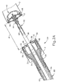
図1〜図6は、それぞれより詳細に後述される、ステープル留めヘッドアセンブリ(20)、軸アセンブリ(60)、及びアクチュエータハンドルアセンブリ(70)を有する、代表的な円形外科用ステープル留め器具(10)を示す。軸アセンブリ(60)は、アクチュエータハンドルアセンブリ(70)から遠位側に延在し、ステープル留めヘッドアセンブリ(20)は軸アセンブリ(60)の遠位端に連結される。概して、アクチュエータハンドルアセンブリ(70)は、ステープル留めヘッドアセンブリ(20)のステープルドライバ(24)を作動させて、複数のステープル(66)をステープル留めヘッドアセンブリ(20)から送り出すように動作可能である。ステープル(66)は曲げられて、器具(10)の遠位端に取り付けられたアンビル(40)によって完全なステープルを形成する。結果的に、図2A〜図2Cに示される組織(2)が、器具(10)を使用してステープル留めされてもよい。
I. Exemplary Circular Stapling Surgical Instrument Overview FIGS. 1-6 have a stapling head assembly (20), a shaft assembly (60), and an actuator handle assembly (70), each described in more detail below. A representative circular surgical stapling instrument (10) is shown. The shaft assembly (60) extends distally from the actuator handle assembly (70) and the stapling head assembly (20) is coupled to the distal end of the shaft assembly (60). In general, the actuator handle assembly (70) is operable to actuate the staple driver (24) of the stapling head assembly (20) to deliver a plurality of staples (66) from the stapling head assembly (20). . Staple (66) is bent to form a complete staple with an anvil (40) attached to the distal end of instrument (10). As a result, the tissue (2) shown in FIGS. 2A-2C may be stapled using the instrument (10).
本実施例では、器具(10)は閉鎖システム及び発射システムを備える。閉鎖システムは、トロカール(38)、トロカールアクチュエータ(39)、及び回転ノブ(98)を備える。アンビル(40)は、トロカール(38)の遠位端に連結されてもよい。回転ノブ(98)は、トロカール(38)をステープル留めヘッドアセンブリ(20)に対して長手方向で並進させ、それによって、アンビル(40)がトロカール(38)に連結されているときにアンビル(40)を並進させて、アンビル(40)とステープル留めヘッドアセンブリ(20)との間に組織をクランプするように動作可能である。発射システムは、トリガ(74)、トリガ作動アセンブリ(84)、ドライバアクチュエータ(64)、及びステープルドライバ(24)を備える。ステープルドライバ(24)は、ステープルドライバ(24)を長手方向で作動させると組織を切断するように構成されたナイフ(36)を含む。それに加えて、ステープルドライバ(24)を長手方向で作動させると、ステープルドライバ(24)がステープル(66)も遠位側に駆動するように、ステープル(66)は、ステープルドライバ(24)の複数のステープル駆動部材(30)の遠位側に位置付けられる。したがって、トリガ(74)を作動させ、ドライバアクチュエータ(64)を介してトリガ作動アセンブリ(84)がステープルドライバ(24)を作動させると、ナイフ(36)及び部材(30)がほぼ同時に組織(2)を切断すると共にステープル(66)をステープル留めヘッドアセンブリ(20)に対して遠位側で組織へと送り込む。閉鎖システム及び発射システムの構成要素と機能性について、次により詳細に記載する。 In this example, the instrument (10) comprises a closure system and a firing system. The closure system includes a trocar (38), a trocar actuator (39), and a rotation knob (98). Anvil (40) may be coupled to the distal end of trocar (38). The rotation knob (98) translates the trocar (38) longitudinally relative to the stapling head assembly (20), thereby causing the anvil (40) when the anvil (40) is coupled to the trocar (38). ) To translate the tissue between the anvil (40) and the stapling head assembly (20). The firing system includes a trigger (74), a trigger actuation assembly (84), a driver actuator (64), and a staple driver (24). The staple driver (24) includes a knife (36) configured to cut tissue when the staple driver (24) is actuated longitudinally. In addition, the staple (66) may be more than one of the staple drivers (24) such that when the staple driver (24) is actuated longitudinally, the staple driver (24) also drives the staples (66) distally. Of the staple drive member (30). Thus, when the trigger (74) is actuated and the trigger actuating assembly (84) actuates the staple driver (24) via the driver actuator (64), the knife (36) and the member (30) are substantially simultaneously tissue (2 ) And the staple (66) is fed into the tissue distal to the stapling head assembly (20). The components and functionality of the closure system and launch system are described in more detail below.
A.代表的なアンビル
図1〜図2Cに示されるように、アンビル(40)は、器具(10)に選択的に連結して表面を提供することができ、その表面に対抗してステープル(66)が曲げられて、ステープル留めヘッドアセンブリ(20)とアンビル(40)との間に収容された物質をステープル留めしてもよい。本実施例のアンビル(40)は、ステープル留めヘッドアセンブリ(20)に対して遠位側に延在する、トロカール又は先の尖ったロッド(38)に選択的に連結可能である。図2A〜図2Cを参照すると、アンビル(40)は、アンビル(40)の近位軸(42)をトロカール(38)の遠位先端に連結することによって、選択的に連結可能である。アンビル(40)は、全体的に円形のアンビルヘッド(48)と、アンビルヘッド(48)から近位側に延在する近位軸(42)とを備える。図示される実施例では、近位軸(42)は、アンビル(40)をトロカール(38)に選択的に連結する、弾性的に付勢される保定クリップ(46)を有する管状部材(44)を備えるが、これは単に任意のものであり、アンビル(40)をトロカール(38)に連結する他の保定機構が同様に使用されてもよいことが理解されるべきである。例えば、C型クリップ、クランプ、ねじ切り、ピン、接着剤などが、アンビル(40)をトロカール(38)に連結するのに用いられてもよい。それに加えて、アンビル(40)はトロカール(38)に選択的に連結可能なものとして記載されているが、いくつかの型においては、近位軸(42)は、アンビル(40)が一旦取り付けられるとアンビル(40)をトロカール(38)から除去できないような、一方向の連結機構を含んでもよい。単に例示の一方向特徴部は、かかり、一方向スナップ、コレット、カラー、留め金、バンドなどを含む。勿論、アンビル(40)をトロカール(38)に結合するための更に他の構成は、本明細書の教示を考慮することで当業者には明らかとなるであろう。例えば、トロカール(38)は、代わりに中空軸であってもよく、近位軸(42)は、中空軸に挿入可能な尖らせたロッドを備えてもよい。
A. Exemplary Anvil As shown in FIGS. 1-2C, the anvil (40) can be selectively connected to the instrument (10) to provide a surface against the surface (66). May be bent to staple the material contained between the stapling head assembly (20) and the anvil (40). The anvil (40) of this example is selectively connectable to a trocar or pointed rod (38) that extends distally relative to the stapling head assembly (20). With reference to FIGS. 2A-2C, the anvil (40) can be selectively coupled by coupling the proximal shaft (42) of the anvil (40) to the distal tip of the trocar (38). The anvil (40) comprises a generally circular anvil head (48) and a proximal shaft (42) extending proximally from the anvil head (48). In the illustrated embodiment, the proximal shaft (42) has a tubular member (44) having an elastically biased retaining clip (46) that selectively couples the anvil (40) to the trocar (38). Although this is merely optional, it should be understood that other retaining mechanisms for connecting the anvil (40) to the trocar (38) may be used as well. For example, a C-clip, clamp, threading, pin, adhesive, etc. may be used to connect the anvil (40) to the trocar (38). In addition, although the anvil (40) is described as being selectively connectable to the trocar (38), in some types, the proximal shaft (42) is once attached to the anvil (40). A one-way coupling mechanism may be included so that once the anvil (40) cannot be removed from the trocar (38). Simply exemplary one-way features include barbs, one-way snaps, collets, collars, clasps, bands, and the like. Of course, still other configurations for coupling the anvil (40) to the trocar (38) will be apparent to those skilled in the art in view of the teachings herein. For example, the trocar (38) may instead be a hollow shaft and the proximal shaft (42) may comprise a pointed rod that can be inserted into the hollow shaft.
本実施例のアンビルヘッド(48)は、アンビルヘッド(48)の近位面(50)に形成された複数のステープル形成ポケット(52)を備える。結果的に、図2Cに示されるように、アンビル(40)が閉位置にあり、ステープル(66)がステープル留めヘッドアセンブリ(20)から送り出されてステープル形成ポケット(52)に送り込まれると、ステープル(66)の脚部(68)が曲げられて、完成したステープルが形成される。 The anvil head (48) of this example includes a plurality of staple forming pockets (52) formed in the proximal face (50) of the anvil head (48). As a result, as shown in FIG. 2C, when the anvil (40) is in the closed position and the staple (66) is fed out of the stapling head assembly (20) and into the staple forming pocket (52), the staples The leg (68) of (66) is bent to form the finished staple.
アンビル(40)を別個の構成要素として、アンビル(40)は、ステープル留めヘッドアセンブリ(20)に連結されるのに先立って、組織(2)の一部分に挿入され固定されてもよいことが理解されるべきである。単なる一例として、アンビル(40)は、組織(2)の第1の管状部分に挿入され固定されてもよく、器具(10)は、組織(2)の第2の管状部分に挿入され固定されてもよい。例えば、組織(2)の第1の管状部分は、アンビル(40)の一部分又はその周りに縫合されてもよく、組織(2)の第2の管状部分は、トロカール(38)又はその周りに縫合されてもよい。 It will be appreciated that with the anvil (40) as a separate component, the anvil (40) may be inserted and secured to a portion of the tissue (2) prior to being coupled to the stapling head assembly (20). It should be. By way of example only, the anvil (40) may be inserted and secured in the first tubular portion of the tissue (2), and the instrument (10) is inserted and secured in the second tubular portion of the tissue (2). May be. For example, the first tubular portion of tissue (2) may be sutured around or around a portion of the anvil (40), and the second tubular portion of tissue (2) may be around trocar (38) or around it. It may be sutured.
図2Aに示されるように、アンビル(40)は次にトロカール(38)に連結される。本実施例のトロカール(38)は、最遠位の作動位置で示される。かかるトロカール(38)の伸長位置は、アンビル(40)の取付けに先立って組織(2)が連結されてもよい、より広い面積を提供してもよい。それに加えて、トロカール(38)の伸長位置はまた、トロカール(38)に対するアンビル(40)の取付けをより簡単にしてもよい。トロカール(38)は先細の遠位先端を更に含む。かかる先端は、組織を穿孔し、かつ/又はトロカール(38)上へのアンビル(40)の挿入を支援することが可能であってもよいが、先細の遠位先端は単に任意のものである。例えば、他の型においては、トロカール(38)は鈍端部を有してもよい。それに加えて、又はその代わりに、トロカール(38)は、アンビル(40)をトロカール(38)に向かって引き付けてもよい、磁性部分(図示なし)を含んでもよい。当然ながら、アンビル(40)及びトロカール(38)の更なる別の構成及び配置は、本明細書の教示を考慮して当業者には明白となるであろう。 As shown in FIG. 2A, the anvil (40) is then coupled to the trocar (38). The trocar (38) of this example is shown in its most distal operating position. Such an extended position of the trocar (38) may provide a larger area to which the tissue (2) may be connected prior to attachment of the anvil (40). In addition, the extended position of the trocar (38) may also make attachment of the anvil (40) to the trocar (38) easier. Trocar (38) further includes a tapered distal tip. Such a tip may be capable of piercing tissue and / or assisting insertion of the anvil (40) onto the trocar (38), but the tapered distal tip is merely optional. . For example, in other molds, the trocar (38) may have a blunt end. In addition or alternatively, the trocar (38) may include a magnetic portion (not shown) that may attract the anvil (40) toward the trocar (38). Of course, further alternative configurations and arrangements of the anvil (40) and trocar (38) will be apparent to those skilled in the art in view of the teachings herein.
アンビル(40)がトロカール(38)に連結される際、アンビル(40)の近位面とステープル留めヘッドアセンブリ(20)の遠位面との間の距離によって、間隙距離dが規定される。本実施例のトロカール(38)は、より詳細に後述するように、アクチュエータハンドルアセンブリ(70)の近位端に位置する調節ノブ(98)を介して、ステープル留めヘッドアセンブリ(20)に対して長手方向で並進可能である。結果的に、アンビル(40)がトロカール(38)に連結されると、ステープル留めヘッドアセンブリ(20)に対してアンビル(40)を作動させることにより、調節ノブ(98)の回転によって間隙距離dが拡大又は縮小する。例えば、図2A〜図2Bに連続的に示されるように、アンビル(40)は、アクチュエータハンドルアセンブリ(70)に対して初期の開位置から閉位置へと近位側に作動して示されており、それによって間隙距離dが縮小し、組織(2)の2つの一部分の間の距離が接合される。一旦間隙距離dが所定の範囲内になると、図2Cに示されるように、ステープル留めヘッドアセンブリ(20)が発射されて、アンビル(40)とステープル留めヘッドアセンブリ(20)との間の組織(2)をステープル留めし、切断してもよい。ステープル留めヘッドアセンブリ(20)は、より詳細に後述するように、ユーザがアクチュエータハンドルアセンブリ(70)のトリガ(74)を枢動させることによって、組織(2)をステープル留めし切断するように動作可能である。一部の他の型では、ステープル留めヘッドアセンブリ(20)は、モーターによって作動されるか、又は別の方法で動かされる。 When the anvil (40) is coupled to the trocar (38), the distance between the proximal surface of the anvil (40) and the distal surface of the stapling head assembly (20) defines a gap distance d. The trocar (38) of this example is relative to the stapling head assembly (20) via an adjustment knob (98) located at the proximal end of the actuator handle assembly (70), as will be described in more detail below. Translation in the longitudinal direction is possible. As a result, when the anvil (40) is coupled to the trocar (38), actuating the anvil (40) relative to the stapling head assembly (20) causes rotation of the adjustment knob (98) to cause a gap distance d. Expands or contracts. For example, as shown continuously in FIGS. 2A-2B, the anvil (40) is shown operating proximally from an initial open position to a closed position relative to the actuator handle assembly (70). Thereby reducing the gap distance d and joining the distance between the two parts of the tissue (2). Once the gap distance d is within the predetermined range, as shown in FIG. 2C, the stapling head assembly (20) is fired and the tissue between the anvil (40) and the stapling head assembly (20) ( 2) may be stapled and cut. The stapling head assembly (20) operates to staple and cut tissue (2) by the user pivoting the trigger (74) of the actuator handle assembly (70), as described in more detail below. Is possible. In some other types, the stapling head assembly (20) is actuated by a motor or otherwise moved.
上述したように、間隙距離dは、アンビル(40)とステープル留めヘッドアセンブリ(20)との間の距離に相当する。器具(10)が患者に挿入されると、この間隙距離dは簡単に視認できないことがある。結果的に、図5〜図6に示される可動のインジケータバー(110)が、トリガ(74)の反対側に位置付けられたインジケータ窓(120)を通して視認できるように設けられる。インジケータバー(110)は、インジケータバー(110)の位置が間隙距離dを表すように、調節ノブ(98)の回転に反応して移動するように動作可能である。図6に示されるように、インジケータ窓(120)は、アンビルの間隙が所望の動作範囲(例えば、緑色の範囲もしくは「グリーンゾーン(green zone)」)内にあることを示す目盛(130)と、目盛り(130)の各端部にあるそれに対応するステープル圧縮表示とを更に備える。単なる一例として、図6に示されるように、第1のステープル画像(132)は大きなステープル高さを描写し、第2のステープル画像(134)は小さなステープル高さを描写する。結果的に、ユーザは、インジケータバー(110)及び目盛(130)を介して、ステープル留めヘッドアセンブリ(20)に対する連結されたアンビル(40)の位置を視認することができる。ユーザは、次に、調節ノブ(98)を介してアンビル(40)の位置決めを適宜調節してもよい。 As described above, the gap distance d corresponds to the distance between the anvil (40) and the stapling head assembly (20). When the instrument (10) is inserted into the patient, this gap distance d may not be easily visible. As a result, the movable indicator bar (110) shown in FIGS. 5-6 is provided to be visible through an indicator window (120) positioned on the opposite side of the trigger (74). The indicator bar (110) is operable to move in response to the rotation of the adjustment knob (98) such that the position of the indicator bar (110) represents the gap distance d. As shown in FIG. 6, the indicator window (120) includes a scale (130) indicating that the anvil gap is within a desired operating range (eg, a green range or “green zone”); And a corresponding staple compression display at each end of the scale (130). By way of example only, as shown in FIG. 6, the first staple image (132) depicts a large staple height and the second staple image (134) depicts a small staple height. As a result, the user can view the position of the connected anvil (40) relative to the stapling head assembly (20) via the indicator bar (110) and the scale (130). The user may then adjust the positioning of the anvil (40) as appropriate via the adjustment knob (98).
再び図2A〜図2Cを参照すると、ユーザは、アンビルヘッド(48)がステープル留めされる組織(2)の一部分内に位置するようにして、組織(2)の一部分を管状部材(44)の周りで縫合する。組織(2)がアンビル(40)に取り付けられると、保定クリップ(46)及び管状部材(44)の一部分が組織(2)から突出するので、ユーザはアンビル(40)をトロカール(38)に連結してもよい。組織(2)がトロカール(38)及び/又はステープル留めヘッドアセンブリ(20)の別の一部分に連結された状態で、ユーザは、アンビル(40)をトロカール(38)に取り付け、アンビル(40)をステープル留めヘッドアセンブリ(20)に向かって近位側に作動させて、間隙距離dを縮小させる。一旦器具(10)が動作範囲内になると、ユーザは次に、組織(2)の端部を互いにステープル留めし、それによって組織(2)の実質的に連続した管状部分が形成される。 Referring again to FIGS. 2A-2C, the user places a portion of tissue (2) on the tubular member (44) such that the anvil head (48) is located within the portion of tissue (2) to be stapled. Suture around. When the tissue (2) is attached to the anvil (40), the retaining clip (46) and a portion of the tubular member (44) protrude from the tissue (2) so that the user connects the anvil (40) to the trocar (38). May be. With tissue (2) coupled to trocar (38) and / or another portion of stapling head assembly (20), the user attaches anvil (40) to trocar (38) and attaches anvil (40). Acting proximally towards the stapling head assembly (20) reduces the gap distance d. Once the instrument (10) is within the operating range, the user then staples the ends of the tissue (2) together, thereby forming a substantially continuous tubular portion of the tissue (2).
アンビル(40)は、更に、参照により開示が本明細書に組み込まれる、米国特許第5,205,459号、米国特許第5,271,544号、米国特許第5,275,322号、米国特許第5,285,945号、米国特許第5,292,053号、米国特許第5,333,773号、米国特許第5,350,104号、米国特許第5,533,661号の教示の少なくとも一部にしたがって、及び/又は、本明細書の教示を考慮して当業者には明白となるであろう他の構成にしたがって構築されてもよい。 Anvil (40) is further described in US Pat. No. 5,205,459, US Pat. No. 5,271,544, US Pat. No. 5,275,322, the disclosure of which is incorporated herein by reference. Teachings of US Pat. No. 5,285,945, US Pat. No. 5,292,053, US Pat. No. 5,333,773, US Pat. No. 5,350,104, US Pat. No. 5,533,661 May be constructed in accordance with at least a portion of and / or other configurations that will be apparent to those skilled in the art in view of the teachings herein.
B.代表的なステープル留めヘッドアセンブリ
本実施例のステープル留めヘッドアセンブリ(20)は、軸アセンブリ(60)の遠位端に連結され、スライド可能なステープルドライバ(24)を収納する管状ケーシング(22)と、ステープルポケット(32)内に収容された複数のステープル(66)とを備える。ステープル(66)及びステープルポケット(32)は、管状ケーシング(22)の周りの円形アレイ内に配設される。本実施例では、ステープル(66)及びステープルポケット(32)は、ステープル(66)及びステープルポケット(32)の同心の環状列の対の形で配設される。ステープルドライバ(24)は、アクチュエータハンドルアセンブリ(70)のトリガ(74)の回転に反応して、管状ケーシング(22)内で長手方向で作動するように動作可能である。図2A〜図2Cに示されるように、ステープルドライバ(24)は、トロカール開口部(26)と、中央凹部(28)と、中央凹部(28)の周りに円周方向で配設されると共に、軸アセンブリ(60)に対して遠位側に延在する複数の部材(30)とを有する、フレア形状の円筒状部材を備える。各部材(30)は、複数のステープル(66)のうち対応するステープル(66)に接触し、それをステープルポケット(32)内で係合するように構成される。結果的に、ステープルドライバ(24)をアクチュエータハンドルアセンブリ(70)に対して遠位側に作動させると、各部材(30)が、管状ケーシング(22)の遠位端に形成されたステープルアパーチャ(34)を通して、対応するステープル(66)をそのステープルポケット(32)から送り出す。各部材(30)はステープルドライバ(24)から延在するので、複数のステープル(66)は、ほぼ同時にステープル留めヘッドアセンブリ(20)から送り出される。アンビル(40)が閉位置にあるとき、ステープル(66)はステープル形成ポケット(52)に送り込まれてステープル(66)の脚部(68)が曲がり、それによってアンビル(40)とステープル留めヘッドアセンブリ(20)との間に位置する物質をステープル留めする。図3は、部材(30)によってアンビル(40)のステープル形成ポケット(32)に送り込まれて脚部(68)を曲げる、1つの単なる代表的なステープル(66)を示す。
B. Exemplary Stapling Head Assembly The stapling head assembly (20) of this example includes a tubular casing (22) coupled to the distal end of the shaft assembly (60) and containing a slidable staple driver (24). A plurality of staples (66) housed in the staple pocket (32). Staples (66) and staple pockets (32) are arranged in a circular array around tubular casing (22). In this example, staples (66) and staple pockets (32) are arranged in pairs of concentric annular rows of staples (66) and staple pockets (32). The staple driver (24) is operable to operate longitudinally within the tubular casing (22) in response to rotation of the trigger (74) of the actuator handle assembly (70). As shown in FIGS. 2A-2C, the staple driver (24) is disposed circumferentially around the trocar opening (26), the central recess (28), and the central recess (28). A flared cylindrical member having a plurality of members (30) extending distally relative to the shaft assembly (60). Each member (30) is configured to contact a corresponding staple (66) of the plurality of staples (66) and engage it within the staple pocket (32). Consequently, when the staple driver (24) is actuated distally with respect to the actuator handle assembly (70), each member (30) has a staple aperture ( 34) through the corresponding staple (66) out of its staple pocket (32). As each member (30) extends from the staple driver (24), a plurality of staples (66) are delivered from the stapling head assembly (20) at substantially the same time. When the anvil (40) is in the closed position, the staple (66) is fed into the staple forming pocket (52) and the legs (68) of the staple (66) bend, thereby causing the anvil (40) and stapling head assembly. Staple the material located between (20). FIG. 3 shows one simple representative staple (66) that is fed by members (30) into the staple forming pocket (32) of the anvil (40) to bend the legs (68).
ステープルドライバ(24)は、トロカール開口部(26)と同軸であってステープルポケット(32)から差し込まれる、円筒状のナイフ(36)を更に含む。本実施例では、円筒状のナイフ(36)は中央凹部(28)内に配設されて、ステープルドライバ(24)と共に遠位側に並進する。アンビル(40)がトロカール(38)に固定されると、上記したように、アンビルヘッド(48)が表面を提供し、それに接して円筒状のナイフ(36)が、アンビル(40)とステープル留めヘッドアセンブリ(20)との間に収容された物質を切り離す。いくつかの型においては、アンビルヘッド(48)は、(例えば、協働する剪断縁部を提供することによって)物質を切り離すのを支援するため、円筒状のナイフ(36)のための凹部(図示なし)を含んでもよい。それに加えて、又はその代わりに、アンビルヘッド(48)は、鋏式の切断作用が提供されてもよいように、円筒状のナイフ(36)から片寄った1つ以上の向かい合った円筒状のナイフ(図示なし)を含んでもよい。更なる他の構成が、本明細書の教示を考慮することで当業者には明らかとなるであろう。ステープル留めヘッドアセンブリ(20)は、したがって、アクチュエータハンドルアセンブリ(70)による作動に反応して、組織(2)のステープル留め及び切断の両方をほぼ同時に行うように動作可能である。 The staple driver (24) further includes a cylindrical knife (36) that is coaxial with the trocar opening (26) and is inserted from the staple pocket (32). In this example, a cylindrical knife (36) is disposed in the central recess (28) and translates distally with the staple driver (24). When the anvil (40) is secured to the trocar (38), as described above, the anvil head (48) provides a surface against which the cylindrical knife (36) is stapled with the anvil (40). The material contained between the head assembly (20) is cut off. In some types, the anvil head (48) is provided with a recess (for a cylindrical knife (36) (eg, by providing a cooperating shearing edge) to assist in separating the material. (Not shown) may be included. In addition or alternatively, the anvil head (48) may include one or more opposed cylindrical knives offset from the cylindrical knife (36) so that a scissor-type cutting action may be provided. (Not shown) may be included. Still other configurations will be apparent to those skilled in the art from consideration of the teachings herein. The stapling head assembly (20) is therefore operable to effect both stapling and cutting of the tissue (2) substantially simultaneously in response to actuation by the actuator handle assembly (70).
当然ながら、ステープル留めヘッドアセンブリ(20)は、更に、参照により開示が本明細書に組み込まれる、米国特許第5,205,459号、米国特許第5,271,544号、米国特許第5,275,322号、米国特許第5,285,945号、米国特許第5,292,053号、米国特許第5,333,773号、米国特許第5,350,104号、米国特許第5,533,661号の教示の少なくとも一部にしたがって、及び/又は、本明細書の教示を考慮して当業者には明白となるであろう他の構成にしたがって構築されてもよい。 Of course, the stapling head assembly (20) is further described in US Pat. No. 5,205,459, US Pat. No. 5,271,544, US Pat. No. 275,322, US Pat. No. 5,285,945, US Pat. No. 5,292,053, US Pat. No. 5,333,773, US Pat. No. 5,350,104, US Pat. It may be constructed in accordance with at least a portion of the teachings of US Pat. No. 533,661 and / or other configurations that will be apparent to those skilled in the art in view of the teachings herein.
上記したように、ステープルドライバ(24)はトロカール開口部(26)を含む。トロカール開口部(26)は、トロカール(38)がステープル留めヘッドアセンブリ(20)及び/又は軸アセンブリ(60)に対して長手方向でスライドできるように構成される。図2A〜図2Cに示されるように、トロカール(38)は、アクチュエータハンドルアセンブリ(70)を参照してより詳細に後述するように、回転ノブ(98)の回転によってトロカール(38)を長手方向で作動させることができるようにして、トロカールアクチュエータ(39)に連結される。本実施例では、トロカールアクチュエータ(39)は、トロカール(38)に連結される細長く比較的剛性の軸を備えるが、これは単に任意のものである。いくつかの型においては、アクチュエータ(39)は、器具(10)の一部分が使用中に選択的に曲げられるか又は湾曲されてもよいように横方向の曲げが可能な、長手方向で剛性の材料を備えてもよく、あるいは、器具(10)は事前設定された曲げ軸アセンブリ(60)を含んでもよい。1つの単なる代表的な材料はニチノールである。アンビル(40)がトロカール(38)に連結されると、トロカール(38)及びアンビル(40)は、アンビル(40)とステープル留めヘッドアセンブリ(20)との間の間隙距離dを調節するため、アクチュエータ(39)を介して並進可能である。トロカール(38)を長手方向で作動させるアクチュエータ(39)の更なる別の構成は、本明細書の教示を考慮して当業者には明白となるであろう。 As described above, the staple driver (24) includes a trocar opening (26). Trocar opening (26) is configured to allow trocar (38) to slide longitudinally relative to stapling head assembly (20) and / or shaft assembly (60). As shown in FIGS. 2A-2C, the trocar (38) can be moved longitudinally by rotation of the rotary knob (98), as described in more detail below with reference to the actuator handle assembly (70). Is connected to the trocar actuator (39). In this embodiment, the trocar actuator (39) comprises an elongated, relatively rigid shaft that is coupled to the trocar (38), but this is merely optional. In some molds, the actuator (39) is longitudinally rigid, allowing lateral bending so that a portion of the instrument (10) may be selectively bent or curved during use. Alternatively, the material (10) may comprise a preset bending axis assembly (60). One mere representative material is nitinol. When the anvil (40) is coupled to the trocar (38), the trocar (38) and the anvil (40) adjust the gap distance d between the anvil (40) and the stapling head assembly (20), Translation is possible via an actuator (39). Still other configurations of the actuator (39) that actuate the trocar (38) in the longitudinal direction will be apparent to those skilled in the art in view of the teachings herein.
C.例示のシャフト組立体
ステープル留めヘッドアセンブリ(20)及びトロカール(38)は、図2A〜図2Cに示されるように、軸アセンブリ(60)の遠位端に位置付けられる。本実施例の軸アセンブリ(60)は、外側管状部材(62)及びドライバアクチュエータ(64)を備える。外側管状部材(62)は、ステープル留めヘッドアセンブリ(20)の管状ケーシング(22)に、かつアクチュエータハンドルアセンブリ(70)の本体(72)に連結され、それによって中の作動構成要素の機械的接地がもたらされる。ドライバアクチュエータ(64)の近位端は、後述するアクチュエータハンドルアセンブリ(70)のトリガ作動アセンブリ(84)に連結される。ドライバアクチュエータ(64)の遠位端は、トリガ(74)の回転によってステープルドライバ(24)を長手方向で作動させるように、ステープルドライバ(24)に連結される。図2A〜図2Cに示されるように、ドライバアクチュエータ(64)は、トロカール(38)に連結されたアクチュエータ(39)がドライバアクチュエータ(64)内でそれに対して長手方向で作動してもよいように、開いた長手方向軸線を有する管状部材を備える。当然ながら、本明細書の教示を考慮して当業者には明白となるように、他の構成要素がドライバアクチュエータ(64)内に配設されてもよいことが理解されるべきである。
C. Exemplary Shaft Assembly The stapling head assembly (20) and trocar (38) are positioned at the distal end of the shaft assembly (60), as shown in FIGS. 2A-2C. The shaft assembly (60) of the present example includes an outer tubular member (62) and a driver actuator (64). The outer tubular member (62) is coupled to the tubular casing (22) of the stapling head assembly (20) and to the body (72) of the actuator handle assembly (70), thereby mechanically grounding the actuating component therein. Is brought about. The proximal end of the driver actuator (64) is coupled to a trigger actuation assembly (84) of the actuator handle assembly (70) described below. The distal end of the driver actuator (64) is coupled to the staple driver (24) such that rotation of the trigger (74) causes the staple driver (24) to operate longitudinally. As shown in FIGS. 2A-2C, the driver actuator (64) allows the actuator (39) coupled to the trocar (38) to operate longitudinally relative to it within the driver actuator (64). And a tubular member having an open longitudinal axis. Of course, it should be understood that other components may be disposed within the driver actuator (64), as will be apparent to those skilled in the art in view of the teachings herein.
軸アセンブリ(60)は、更に、参照により開示が本明細書に組み込まれる、米国特許第5,205,459号、米国特許第5,271,544号、米国特許第5,275,322号、米国特許第5,285,945号、米国特許第5,292,053号、米国特許第5,333,773号、米国特許第5,350,104号、米国特許第5,533,661号の教示の少なくとも一部にしたがって、及び/又は、本明細書の教示を考慮して当業者には明白となるであろう他の構成にしたがって構築されてもよい。 The shaft assembly (60) is further described in US Pat. No. 5,205,459, US Pat. No. 5,271,544, US Pat. No. 5,275,322, the disclosure of which is incorporated herein by reference. US Pat. No. 5,285,945, US Pat. No. 5,292,053, US Pat. No. 5,333,773, US Pat. No. 5,350,104, US Pat. No. 5,533,661 It may be constructed according to at least some of the teachings and / or according to other configurations that will be apparent to those skilled in the art in view of the teachings herein.
D.代表的なアクチュエータハンドルアセンブリ
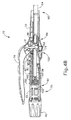
次に図4A〜図5を参照すると、アクチュエータハンドルアセンブリ(70)は、本体(72)、トリガ(74)、ロックアウト機構(82)、トリガ作動アセンブリ(84)、及びトロカール作動アセンブリ(90)を備える。本実施例のトリガ(74)は、本体(72)に枢動可能に装着され、トリガ(74)を発射されてない位置(図4Aに示される)から発射した位置(図4Bに示される)へと回転させることによって、上記のドライバアクチュエータ(64)を作動させるように、トリガ作動アセンブリ(84)に連結される。ばね(78)は、本体(72)及びトリガ(74)に連結されて、トリガ(74)を発射されてない位置に向かって付勢する。ロックアウト機構(82)は、本体(72)に連結される枢動可能な部材である。第1のロック位置では、ロックアウト機構(82)は、ロックアウト機構(82)がトリガ(74)を係合し、ユーザによるトリガ(74)の作動に機械的に抵抗するように、上方へと本体(72)から離れる方向に枢動される。図1及び図4Bに示されるような、第2のロック解除位置では、ロックアウト機構(82)は、トリガ(74)をユーザによって作動させてもよいように、下方へと枢動される。結果的に、ロックアウト機構(82)が第2の位置にあると、トリガ(74)はトリガ作動アセンブリ(84)を係合して、器具(10)を発射することができる。
D. Exemplary Actuator Handle Assembly Referring now to FIGS. 4A-5, an actuator handle assembly (70) includes a body (72), a trigger (74), a lockout mechanism (82), a trigger actuation assembly (84), and A trocar actuation assembly (90) is provided. The trigger (74) of this embodiment is pivotally mounted to the body (72) and the trigger (74) is fired from the position where it is not fired (shown in FIG. 4A) (shown in FIG. 4B). Is coupled to the trigger actuation assembly (84) to actuate the driver actuator (64) described above. Spring (78) is coupled to body (72) and trigger (74) to bias trigger (74) toward an unfired position. The lockout mechanism (82) is a pivotable member coupled to the body (72). In the first locked position, the lockout mechanism (82) moves upward so that the lockout mechanism (82) engages the trigger (74) and mechanically resists actuation of the trigger (74) by the user. And pivoted away from the body (72). In the second unlocked position, as shown in FIGS. 1 and 4B, the lockout mechanism (82) is pivoted downward so that the trigger (74) may be actuated by the user. As a result, when the lockout mechanism (82) is in the second position, the trigger (74) can engage the trigger actuation assembly (84) to fire the instrument (10).
図4A〜図4Bに示されるように、本実施例のトリガ作動アセンブリ(84)は、ドライバアクチュエータ(64)の近位端と係合されたスライド可能なトリガキャリッジ(86)を備える。キャリッジ(86)は、キャリッジ(86)の近位端上に、トリガ(74)から延在する一対のトリガアーム(76)を保定し係合する一連のタブ(88)を含む。結果的に、トリガ(74)を枢動させると、キャリッジ(86)が長手方向で作動し、長手方向の運動をドライバアクチュエータ(64)に伝達する。図示される実施例では、キャリッジ(86)はドライバアクチュエータ(64)の近位端に固定的に連結されるが、これは単なる任意のものである。実際には、1つの単なる代表的な代替例では、キャリッジ(86)は単に、遠位側のばね(図示なし)がドライバアクチュエータ(64)を、アクチュエータハンドルアセンブリ(70)に対して近位側に付勢している状態で、ドライバアクチュエータ(64)に当接してもよい。 As shown in FIGS. 4A-4B, the trigger actuation assembly (84) of this example includes a slidable trigger carriage (86) engaged with the proximal end of the driver actuator (64). The carriage (86) includes a series of tabs (88) on the proximal end of the carriage (86) that retain and engage a pair of trigger arms (76) extending from the trigger (74). As a result, pivoting the trigger (74) causes the carriage (86) to operate longitudinally and transmit longitudinal motion to the driver actuator (64). In the illustrated embodiment, the carriage (86) is fixedly coupled to the proximal end of the driver actuator (64), but this is merely optional. In fact, in one merely representative alternative, the carriage (86) is simply a distal spring (not shown) that drives the driver actuator (64) proximal to the actuator handle assembly (70). The driver actuator (64) may be abutted while being urged.
トリガ作動アセンブリ(84)は、更に、参照により開示が本明細書に組み込まれる、米国特許第5,205,459号、米国特許第5,271,544号、米国特許第5,275,322号、米国特許第5,285,945号、米国特許第5,292,053号、米国特許第5,333,773号、米国特許第5,350,104号、米国特許第5,533,661号の教示の少なくとも一部にしたがって、及び/又は、本明細書の教示を考慮して当業者には明白となるであろう他の構成にしたがって構築されてもよい。 The trigger actuation assembly (84) is further described in US Pat. No. 5,205,459, US Pat. No. 5,271,544, US Pat. No. 5,275,322, the disclosure of which is incorporated herein by reference. US Pat. No. 5,285,945, US Pat. No. 5,292,053, US Pat. No. 5,333,773, US Pat. No. 5,350,104, US Pat. No. 5,533,661 May be constructed in accordance with at least some of the teachings herein and / or according to other configurations that will be apparent to those skilled in the art in view of the teachings herein.
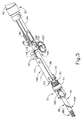
本体(72)はまた、調節ノブ(98)の回転に反応してトロカール(38)を長手方向で作動させるように構成された、トロカール作動アセンブリ(90)を収納する。図4A〜図5に最も良く示されるように、本実施例のトロカール作動アセンブリ(90)は、調節ノブ(98)、溝付きシャンク(94)、及びスリーブ(92)を備える。本実施例の溝付きシャンク(94)は、トロカールアクチュエータ(39)の遠位端に位置するが、溝付きシャンク(94)及びトロカールアクチュエータ(39)は、その代わりに、係合して長手方向移動を伝達する別個の構成要素であってもよいことが理解されるべきである。調節ノブ(98)は、本体(72)の近位端によって回転可能に支持され、内部タブ(図示なし)を介して溝付きシャンク(94)と係合されたスリーブ(92)を回転させるように動作可能である。本実施例の溝付きシャンク(94)は、溝付きシャンク(94)の外表面に形成された連続的な溝(96)を備える。結果的に、調節ノブ(98)を回転させると、内部タブが溝(96)内で浮かび、溝付きシャンク(94)がスリーブ(92)に対して長手方向で作動する。溝付きシャンク(94)はトロカールアクチュエータ(39)の遠位端に位置するので、調節ノブ(98)を第1の方向で回転させることによって、トロカールアクチュエータ(39)がアクチュエータハンドルアセンブリ(70)に対して遠位側に前進する。結果的に、アンビル(40)とステープル留めヘッドアセンブリ(20)との間の間隙距離dが増加する。調節ノブ(98)を反対の方向に回転させることによって、トロカールアクチュエータ(39)がアクチュエータハンドルアセンブリ(70)に対して近位側に作動して、アンビル(40)とステープル留めヘッドアセンブリ(20)との間の間隙距離dが減少する。したがって、トロカール作動アセンブリ(90)は、調節ノブ(98)の回転に反応してトロカール(38)を作動させるように動作可能である。当然ながら、トロカール作動アセンブリ(90)の他の構成は、本明細書の教示を考慮して当業者には明白となるであろう。 The body (72) also houses a trocar actuation assembly (90) configured to actuate the trocar (38) longitudinally in response to rotation of the adjustment knob (98). As best shown in FIGS. 4A-5, the trocar actuation assembly (90) of this example includes an adjustment knob (98), a grooved shank (94), and a sleeve (92). The grooved shank (94) of the present embodiment is located at the distal end of the trocar actuator (39), but the grooved shank (94) and the trocar actuator (39) are instead engaged in the longitudinal direction. It should be understood that it may be a separate component that conveys movement. The adjustment knob (98) is rotatably supported by the proximal end of the body (72) and rotates the sleeve (92) engaged with the grooved shank (94) via an internal tab (not shown). It is possible to operate. The grooved shank (94) of this example comprises a continuous groove (96) formed on the outer surface of the grooved shank (94). As a result, rotating the adjustment knob (98) causes the internal tab to float in the groove (96) and the grooved shank (94) to operate longitudinally relative to the sleeve (92). Since the grooved shank (94) is located at the distal end of the trocar actuator (39), rotating the adjustment knob (98) in the first direction causes the trocar actuator (39) to move to the actuator handle assembly (70). Advances distally. As a result, the gap distance d between the anvil (40) and the stapling head assembly (20) is increased. By rotating the adjustment knob (98) in the opposite direction, the trocar actuator (39) is actuated proximally with respect to the actuator handle assembly (70), and the anvil (40) and stapling head assembly (20). The gap distance d between the two decreases. Accordingly, the trocar actuation assembly (90) is operable to actuate the trocar (38) in response to rotation of the adjustment knob (98). Of course, other configurations of the trocar actuation assembly (90) will be apparent to those skilled in the art in view of the teachings herein.
本実施例の溝(96)は、軸線方向距離当たりの溝のピッチ又は数が様々である、複数の異なる部分(96A、96B、96C)を備える。本例の溝(96)は、遠位部分(96A)、中間部分(96B)、及び近位部分(96C)に分割される。図5に示されるように、遠位部分(96A)は、溝付きシャンク(94)の短い軸線距離にわたって微細なピッチ又は多数の溝を備えるので、短い軸線距離を横断するのに調節ノブ(98)を多数回回転させることを要する。中間部分(96B)は、軸線距離当たりの溝のピッチが比較的まばらであるか、又は溝の数がより少ない区画を備えるので、長い軸線距離を横断するのに要する回転数が比較的少ない。結果的に、間隙距離dは、調節ノブ(98)の比較的少数回の回転によって迅速に減少してもよい。本実施例の近位部分(96C)は、遠位部分(96A)に実質的に類似しており、溝付きシャンク(94)の短い軸線距離にわたって微細なピッチ又は多数の溝を備えるので、短い軸線距離を横断するのに多数回の回転を要する。本実施例の近位部分(96C)は、より詳細に後述するように、アンビル(40)がステープル留めヘッドアセンブリ(20)の実質的に近くにあるとき、スリーブ(92)内に位置付けられるので、インジケータバー(110)は目盛(130)に沿ってインジケータ窓(120)内で移動して、アンビル間隙が所望の動作範囲内にあることを示唆する。結果的に、タブが溝(96)の近位部分(96C)内にあるとき、調節ノブ(98)を一回転させる毎に間隙距離dが少量減少して、微細な調整が提供されてもよい。 The groove (96) of the present example comprises a plurality of different portions (96A, 96B, 96C) with varying pitch or number of grooves per axial distance. The groove (96) in this example is divided into a distal portion (96A), an intermediate portion (96B), and a proximal portion (96C). As shown in FIG. 5, the distal portion (96A) comprises a fine pitch or multiple grooves over the short axial distance of the grooved shank (94) so that the adjustment knob (98 ) Must be rotated many times. The middle section (96B) has a relatively sparse pitch of grooves per axial distance, or comprises a section with fewer grooves, so that the number of revolutions required to traverse a long axial distance is relatively low. As a result, the gap distance d may be quickly reduced by a relatively small number of rotations of the adjustment knob (98). The proximal portion (96C) of this example is substantially similar to the distal portion (96A) and is short because it comprises a fine pitch or multiple grooves over the short axial distance of the grooved shank (94). Many rotations are required to traverse the axial distance. The proximal portion (96C) of the present embodiment is positioned within the sleeve (92) when the anvil (40) is substantially near the stapling head assembly (20), as will be described in more detail below. The indicator bar (110) moves in the indicator window (120) along the scale (130) to indicate that the anvil gap is within the desired operating range. As a result, when the tab is in the proximal portion (96C) of the groove (96), the gap distance d is reduced by a small amount each time the adjustment knob (98) is rotated to provide fine adjustment. Good.
トロカール作動アセンブリ(90)は、更に、参照により開示が本明細書に組み込まれる、米国特許第5,205,459号、米国特許第5,271,544号、米国特許第5,275,322号、米国特許第5,285,945号、米国特許第5,292,053号、米国特許第5,333,773号、米国特許第5,350,104号、米国特許第5,533,661号の教示の少なくとも一部にしたがって、及び/又は、本明細書の教示を考慮して当業者には明白となるであろう他の構成にしたがって構築されてもよい。 Trocar actuation assembly (90) is further described in US Pat. No. 5,205,459, US Pat. No. 5,271,544, US Pat. No. 5,275,322, the disclosure of which is incorporated herein by reference. US Pat. No. 5,285,945, US Pat. No. 5,292,053, US Pat. No. 5,333,773, US Pat. No. 5,350,104, US Pat. No. 5,533,661 May be constructed in accordance with at least some of the teachings herein and / or according to other configurations that will be apparent to those skilled in the art in view of the teachings herein.
図4A〜図4Bに示される実施例では、U字型のクリップ(100)が、溝付きシャンク(94)の遠位側に位置するトロカールアクチュエータ(39)の中間部分に取り付けられる。本実施例では、トロカールアクチュエータ(39)の伸長は、ハンドルアセンブリ(70)の筐体の中のスロットを係合し、それにより、調整ノブ(98)が回転するとき、トロカールアクチュエータ(39)がその軸の周りを回転することを防止する。一部の他の変形例では、U字型のクリップ(100)は、本体(72)の一部分と係合することにより、調整ノブ(98)が回転するときにトロカールアクチュエータ(39)がその軸の周りを回転することを実質的に防止する。本実施例のU字型のクリップ(100)は、取付部材、例えばネジ、ボルト、ピン、クリップなどを受容するために、その対向面のそれぞれの細長いスロット(102)を更に含むことにより、スケール(130)に対してインジケータバー(110)を較正するために、トロカールアクチュエータ(39)に対するU字型のクリップ(100)の細長いスロット(102)の縦方向位置を選択的に調整する。 In the embodiment shown in FIGS. 4A-4B, a U-shaped clip (100) is attached to the middle portion of the trocar actuator (39) located distal to the grooved shank (94). In this example, the extension of the trocar actuator (39) engages a slot in the housing of the handle assembly (70) so that when the adjustment knob (98) rotates, the trocar actuator (39) Prevent rotation around that axis. In some other variations, the U-shaped clip (100) engages a portion of the body (72) so that the trocar actuator (39) is pivoted when the adjustment knob (98) rotates. Is substantially prevented from rotating around. The U-shaped clip (100) of the present embodiment further includes a respective elongated slot (102) on its opposite surface for receiving mounting members such as screws, bolts, pins, clips, etc. To calibrate the indicator bar (110) relative to (130), the longitudinal position of the elongated slot (102) of the U-shaped clip (100) relative to the trocar actuator (39) is selectively adjusted.
図5に示されるように、アクチュエータハンドルアセンブリ(70)は、インジケータ(104)を係合し枢動させるように構成されたインジケータブラケット(140)を更に含む。本実施例のインジケータブラケット(140)は、本体(72)に形成された一対のスロットに沿って、本体(72)に対してスライド可能である。インジケータブラケット(140)は、長方形のプレート(144)、インジケータアーム(146)、及び角度付きのフランジ(142)を備える。角度付きのフランジ(142)は、長方形のプレート(144)の近位端に形成され、トロカールアクチュエータ(39)及び/又は溝付きシャンク(94)上にスライド可能に装着するためのアパーチャ(図示なし)を含む。コイルばね(150)は、フランジ(142)をU字型のクリップ(100)に対して付勢するため、フランジ(142)とボス(152)との間に挟み込まれる。結果的に、U字型のクリップ(100)がトロカールアクチュエータ(39)及び/又は溝付きシャンク(94)によって遠位側に作動すると、コイルばね(150)はインジケータブラケット(140)を付勢して、U字型のクリップ(100)と共に遠位側へと移動させる。それに加えて、トロカールアクチュエータ(39)及び/又は溝付きシャンク(94)が近位側に並進すると、U字型のクリップ(100)は、インジケータブラケット(140)をボス(152)に対して近位側に付勢し、それによってコイルばね(150)が圧縮される。当然ながら、いくつかの型においては、インジケータブラケット(140)は、トロカールアクチュエータ(39)及び/又は溝付きシャンク(94)に固定的に取り付けられてもよいことが理解されるべきである。 As shown in FIG. 5, the actuator handle assembly (70) further includes an indicator bracket (140) configured to engage and pivot the indicator (104). The indicator bracket (140) of this embodiment is slidable with respect to the main body (72) along a pair of slots formed in the main body (72). The indicator bracket (140) comprises a rectangular plate (144), an indicator arm (146), and an angled flange (142). An angled flange (142) is formed at the proximal end of the rectangular plate (144) and is an aperture (not shown) for slidably mounting on the trocar actuator (39) and / or grooved shank (94). )including. The coil spring (150) is sandwiched between the flange (142) and the boss (152) to urge the flange (142) against the U-shaped clip (100). Consequently, when the U-shaped clip (100) is actuated distally by the trocar actuator (39) and / or grooved shank (94), the coil spring (150) biases the indicator bracket (140). And move it distally together with the U-shaped clip (100). In addition, when the trocar actuator (39) and / or grooved shank (94) translates proximally, the U-shaped clip (100) moves the indicator bracket (140) closer to the boss (152). The coil spring (150) is compressed. Of course, it should be understood that in some types, indicator bracket (140) may be fixedly attached to trocar actuator (39) and / or grooved shank (94).
本実施例では、インジケータブラケット(140)が、アンビル間隙が所望の動作範囲(例えば、緑色の領域又は「グリーンゾーン」)内にあるときに相当しない長手方向位置にあるとき、ロックアウト機構(82)の一部分がインジケータブラケット(140)の表面(141)に当接する。アンビル間隙が所望の動作範囲(例えば、緑色の領域又は「グリーンゾーン」)内にあるとき、インジケータブラケット(140)が狭窄して、インジケータアーム(146)のどちらかの側に一対の間隙(145)がもたらされて、ロックアウト機構(82)が枢動することが可能になり、それによってトリガ(74)が解放される。結果的に、ロックアウト機構(82)及びインジケータブラケット(140)は、アンビル(40)が所定の動作範囲内になるまで、ユーザがトリガ(74)を解放し操作するのを実質的に防ぐことができる。当然ながら、いくつかの型においては、ロックアウト機構(82)は全体的に省略されてもよいことが理解されるべきである。 In this example, when the indicator bracket (140) is in a longitudinal position that does not correspond when the anvil gap is within a desired operating range (eg, a green region or "green zone"), the lockout mechanism (82 ) Abuts against the surface (141) of the indicator bracket (140). When the anvil gap is within a desired operating range (eg, a green area or “green zone”), the indicator bracket (140) is constricted and a pair of gaps (145) on either side of the indicator arm (146). ) Is provided, allowing the lockout mechanism (82) to pivot, thereby releasing the trigger (74). As a result, the lockout mechanism (82) and indicator bracket (140) substantially prevent the user from releasing and manipulating the trigger (74) until the anvil (40) is within a predetermined operating range. Can do. Of course, it should be understood that in some types, the lockout mechanism (82) may be omitted entirely.
この動作範囲は、簡潔に上記した、目盛(130)に対して示されるインジケータ(104)のインジケータバー(110)を介して、ユーザに視覚的に通信されてもよい。インジケータブラケット(140)の遠位端には、インジケータ(104)の移動を制御するため、横方向に突出する指(148)で終端する、遠位側に突出するインジケータアーム(146)がある。図5に最も良く示される、インジケータアーム(146)及び指(148)は、インジケータブラケット(140)を長手方向で作動させると、インジケータ(104)が枢動されるようにして、インジケータ(104)のタブ(106)を係合するように構成される。本実施例では、インジケータ(104)は、インジケータ(104)の第1の端部で本体(72)に枢動可能に連結されるが、これは単に任意のものであり、インジケータ(104)の他の枢動点が、本明細書の教示を考慮して当業者には明白となるであろう。インジケータバー(110)は、インジケータブラケット(140)の作動に反応してインジケータバー(110)が移動するように、インジケータ(104)の第2の端部に位置付けられる。結果的に、上記したように、インジケータバー(110)は、アンビル(40)とステープル留めヘッドアセンブリ(20)との間の相対間隙距離dを示すため、目盛(130)(図6に示される)に対してインジケータ窓(120)を通して表示される。 This operating range may be visually communicated to the user via the indicator bar (110) of the indicator (104) shown for the scale (130), briefly described above. At the distal end of the indicator bracket (140) is a distally projecting indicator arm (146) that terminates in a laterally projecting finger (148) to control the movement of the indicator (104). The indicator arm (146) and finger (148), best shown in FIG. 5, cause the indicator (104) to pivot when the indicator bracket (140) is actuated longitudinally, so that the indicator (104) Is configured to engage the tab (106). In this example, the indicator (104) is pivotally connected to the body (72) at the first end of the indicator (104), but this is merely optional and the indicator (104) Other pivot points will be apparent to those skilled in the art in view of the teachings herein. The indicator bar (110) is positioned at the second end of the indicator (104) such that the indicator bar (110) moves in response to actuation of the indicator bracket (140). Consequently, as described above, the indicator bar (110) is shown on the scale (130) (shown in FIG. 6) to indicate the relative gap distance d between the anvil (40) and the stapling head assembly (20). ) Through the indicator window (120).
当然ながら、インジケータブラケット(140)、インジケータ(104)、及び/又はアクチュエータハンドルアセンブリ(70)は、更に、参照により開示が本明細書に組み込まれる、米国特許第5,205,459号、米国特許第5,271,544号、米国特許第5,275,322号、米国特許第5,285,945号、米国特許第5,292,053号、米国特許第5,333,773号、米国特許第5,350,104号、米国特許第5,533,661号の教示の少なくとも一部にしたがって、及び/又は、本明細書の教示を考慮して当業者には明白となるであろう他の構成にしたがって構築されてもよい。 Of course, indicator bracket (140), indicator (104), and / or actuator handle assembly (70) are further described in US Pat. No. 5,205,459, US Pat. No. 5,205,459, the disclosure of which is incorporated herein by reference. US Pat. No. 5,271,544, US Pat. No. 5,275,322, US Pat. No. 5,285,945, US Pat. No. 5,292,053, US Pat. No. 5,333,773, US Pat. Others that will be apparent to those skilled in the art in accordance with at least some of the teachings of US Pat. No. 5,350,104, US Pat. No. 5,533,661, and / or in view of the teachings herein It may be constructed according to the configuration of
II.代表的な経口円形アンビル導入システム
上記したように、アンビル(40)は、アンビル(40)がステープル留めヘッドアセンブリ(20)に連結される前に、組織(2)の一部分に挿入されて固定され得るように、別個の構成要素として提供されてもよい。例えば、患者の胃腸管内での処置(例えば、食道切除)に対して、経口でアンビル(40)を導入することが望ましくあり得る。図7は、食道切除後に、切断された食道区間(2、4)を連結するための吻合処置の初期段階を示す。アンビル(40)は、内視鏡(6)を使用して食道を通して経口で挿入され、食道の第一の切断区間(2)内に設置される。器具(10)は、胃を通して挿入され、食道の第二の切断区間(4)内に設置される。アンビル(40)は、次に、器具(10)のトロカール(38)に連結されて、食道の切断区間(2、4)を吻合でステープル留め及び密閉する。アンビル(40)は、また、本明細書の教示を考慮すれば当業者にとって明らかであろうように、吻合を実行するために胃腸管の他の身体の管腔又は領域内に挿入されてもよい。アンビル(40)の不適切な導入は、食道を刺激し得るので、アンビル(40)を身体管腔を通して滑らかに挿入するために経口円形アンビル導入システムを提供することが望ましい場合がある。アンビル導入システムは、挿入中に、たとえ挿入中にアンビル(40)全体ではなくとも、少なくともアンビル(40)の近位側を覆うための拡大特徴を備えてもよく、又は、システムが、アンビル(40)の近位側が組織から離れる方を向くようにアンビル(40)を逆さまに挿入するためのアンビル把持特徴を備えてもよい。そのような特徴の様々な実施例が以下において更に詳しく記述されるが、一方、他の実施例は、本明細書の教示を考慮すれば当業者にとって明らかであろう。
II. Exemplary Oral Circular Anvil Introduction System As noted above, the anvil (40) is inserted and secured into a portion of the tissue (2) before the anvil (40) is coupled to the stapling head assembly (20). As obtained, it may be provided as a separate component. For example, it may be desirable to introduce an anvil (40) orally for treatment within the patient's gastrointestinal tract (eg, esophagectomy). FIG. 7 shows the initial stage of the anastomosis procedure to connect the cut esophageal segments (2, 4) after esophagectomy. The anvil (40) is inserted orally through the esophagus using the endoscope (6) and placed in the first cut section (2) of the esophagus. The instrument (10) is inserted through the stomach and placed in the second cutting section (4) of the esophagus. The anvil (40) is then coupled to the trocar (38) of the instrument (10) to staple and seal the esophageal cutting section (2, 4) with anastomosis. The anvil (40) may also be inserted into other body lumens or regions of the gastrointestinal tract to perform an anastomosis, as will be apparent to those skilled in the art in view of the teachings herein. Good. Since improper introduction of the anvil (40) may irritate the esophagus, it may be desirable to provide an oral circular anvil introduction system for smooth insertion of the anvil (40) through the body lumen. The anvil introduction system may include an enlarged feature to cover at least the proximal side of the anvil (40) during insertion, even if not the entire anvil (40) during insertion, or the system may include an anvil ( An anvil gripping feature may be provided for inserting the anvil (40) upside down so that the proximal side of 40) faces away from the tissue. Various embodiments of such features are described in further detail below, while other embodiments will be apparent to those skilled in the art in view of the teachings herein.
A.代表的な拡大特徴
アンビル導入システムは、挿入中に、アンビル(40)の近位側を覆うように膨張又は伸長するアンビル拡大特徴を備えてもよい。かかる拡大特徴は、アンビル(40)が所望の吻合部位に到達するように食道を通して移送されるとき、アンビル(40)の近位側の外側周辺縁が食道の内壁に沿って引きずられることを防止し得る。そのような特徴の様々な実施例が以下において更に詳しく記述されるが、一方、他の実施例は、本明細書の教示を考慮すれば当業者にとって明らかであろう。
A. Exemplary Expansion Features An anvil introduction system may include an anvil expansion feature that expands or extends to cover the proximal side of the anvil (40) during insertion. Such an enlarged feature prevents the proximal outer peripheral edge of the anvil (40) from being dragged along the inner wall of the esophagus when the anvil (40) is transported through the esophagus to reach the desired anastomosis site. Can do. Various embodiments of such features are described in further detail below, while other embodiments will be apparent to those skilled in the art in view of the teachings herein.
1.代表的な膨張可能特徴
代表的な経口円形アンビル導入システム(200)が図8〜図10に示される。本実施例のアンビル導入システム(200)は、膨張可能ブラダー(210)のような拡大特徴を備え、この拡大特徴は、生来の身体管腔(例えば、食道)を通るアンビル(240)の導入中に、アンビル(240)の任意の鋭い縁を覆うためにアンビル(240)の周りで拡張可能である。例えば、図8に示されるように、アンビル導入システム(200)は、アンビル(240)と、膨張可能ブラダー(210)と、可撓性チューブ(222)と、を備える。アンビル(240)は、上述のアンビル(40)と類似している。アンビル(240)は、アンビル(240)の近位面(250)において整列されたステープルポケット(252)を備える。アンビル(240)は、また、近位に延在するシャフト(244)を備える。シャフト(244)は、膨張可能ブラダー(210)に連結されている。膨張可能ブラダー(210)は、図9Bに示されるように、シャフト(244)の周りを巻き、ステープルポケット(252)及びアンビル(240)の近位面(250)の縁を覆うように膨張する可撓性膜を備える。膨張状態において、ブラダー(210)は、アンビル(240)からテーパー形状を画定する。アパーチャ(211)がシャフト(244)に提供され、空気、塩類溶液、又は他の流体がシャフト(244)を通過してブラダー(210)を膨張させることを可能にする。管状部材(212)は、ブラダー(210)から延在することにより、ブラダー(210)を可撓性チューブ(222)に選択的に連結する。シャフト(244)は、アンビル(40)の近位シャフト(42)に類似していることにより、一旦アンビル(240)がステープル留めのために設置されると、シャフト(244)がトロカール(38)と連結するように構成される。
1. Exemplary Inflatable Features A typical oral circular anvil introduction system (200) is shown in FIGS. The anvil introduction system (200) of this example includes an enlarged feature, such as an inflatable bladder (210), that is enlarged during the introduction of the anvil (240) through the native body lumen (eg, esophagus). And expandable around the anvil (240) to cover any sharp edges of the anvil (240). For example, as shown in FIG. 8, an anvil introduction system (200) comprises an anvil (240), an inflatable bladder (210), and a flexible tube (222). Anvil (240) is similar to anvil (40) described above. Anvil (240) includes staple pockets (252) aligned at the proximal surface (250) of anvil (240). The anvil (240) also includes a shaft (244) extending proximally. The shaft (244) is connected to the inflatable bladder (210). The inflatable bladder (210) wraps around the shaft (244) and expands over the edges of the staple pocket (252) and the proximal surface (250) of the anvil (240), as shown in FIG. 9B. A flexible membrane is provided. In the inflated state, the bladder (210) defines a tapered shape from the anvil (240). An aperture (211) is provided on the shaft (244) to allow air, saline, or other fluid to pass through the shaft (244) and expand the bladder (210). Tubular member (212) extends from bladder (210) to selectively couple bladder (210) to flexible tube (222). The shaft (244) is similar to the proximal shaft (42) of the anvil (40) so that once the anvil (240) is installed for stapling, the shaft (244) is trocar (38). Configured to connect with.
可撓性チューブ(222)は、スナップ特徴(220)と、膨張チューブ(224)と、を備える。スナップ特徴(220)は、可撓性チューブ(222)の遠位端から延在している。スナップ特徴(220)は、図9Aに示されるように、管状部材(212)よりも小さい直径を備えることにより、スナップ特徴(220)は、管状部材(212)の中に滑り込むか、又はきちんと嵌って、可撓性チューブ(222)を管状部材(212)に連結する。スナップ特徴(220)は、また、管状部材(212)よりも大きい直径を有することにより、スナップ特徴(220)は、管状部材(212)の周りをスライドし得る。スナップ特徴(220)は、また、管状部材(212)に縫合され得る。可撓性チューブ(222)を管状部材(212)に連結する他の好適な方法は、本明細書の教示に基づけば当業者にとって明らかであろう。膨張チューブ(224)は、可撓性チューブ(222)の内部に設置される。膨張チューブは、ブラダー(210)の中に流体を注入して、ブラダー(210)を膨張させるために用いられ得る。しかしながら、膨張チューブ(224)は、単に選択的であるにすぎず、可撓性チューブ(222)がブラダー(210)の中に流体を注入するために用いられてもよい。可撓性チューブ(222)は、従来のNG(経鼻胃)チューブ又は任意の他の好適な構造を備えていてもよい。 The flexible tube (222) comprises a snap feature (220) and an inflation tube (224). The snap feature (220) extends from the distal end of the flexible tube (222). The snap feature (220) has a smaller diameter than the tubular member (212), as shown in FIG. 9A, so that the snap feature (220) slides or fits into the tubular member (212). The flexible tube (222) to the tubular member (212). The snap feature (220) also has a larger diameter than the tubular member (212) so that the snap feature (220) can slide around the tubular member (212). The snap feature (220) can also be sewn to the tubular member (212). Other suitable methods of connecting the flexible tube (222) to the tubular member (212) will be apparent to those skilled in the art based on the teachings herein. The inflation tube (224) is placed inside the flexible tube (222). The inflation tube can be used to inject fluid into the bladder (210) to inflate the bladder (210). However, the inflation tube (224) is merely optional and a flexible tube (222) may be used to inject fluid into the bladder (210). The flexible tube (222) may comprise a conventional NG (nasogastric) tube or any other suitable structure.
図9Aに示されるように、スナップ特徴(200)は、可撓性チューブ(222)を管状部材(212)に連結するために、管状部材(212)に挿入される。一旦連結されると、膨張チューブ(224)は、図9Bに示されるように、ブラダー(210)を膨張させるために流体をブラダー(210)の中に導入する。ブラダー(210)が膨張させられるとともに、ブラダー(210)は、ステープルポケット(252)を覆う。ブラダー(210)は、また、アンビル(240)を越えて伸長することにより、環状の突出部(214)を形成して、アンビル(240)の近位面(250)の縁を覆う。図10に示されるように、膨張状態において、可撓性チューブ(222)は、アンビル(240)を生来の身体管腔(例えば、食道)を通して円滑に引くために使用される。一旦アンビル(240)がアンビル導入システム(200)によって設置されると、ブラダー(210)は、流体を膨張チューブ(224)を戻る方向に通過させることによって収縮させられる。可撓性チューブ(222)は、次に、アンビル(240)から除去され、アンビル(240)は、動作のために円形外科用ステープル留め器具(10)のトロカール(38)に連結される。 As shown in FIG. 9A, the snap feature (200) is inserted into the tubular member (212) to connect the flexible tube (222) to the tubular member (212). Once connected, the inflation tube (224) introduces fluid into the bladder (210) to inflate the bladder (210), as shown in FIG. 9B. As the bladder (210) is inflated, the bladder (210) covers the staple pocket (252). The bladder (210) also extends beyond the anvil (240) to form an annular protrusion (214) that covers the edge of the proximal surface (250) of the anvil (240). As shown in FIG. 10, in the expanded state, the flexible tube (222) is used to smoothly pull the anvil (240) through the native body lumen (eg, esophagus). Once the anvil (240) is installed by the anvil introduction system (200), the bladder (210) is deflated by passing fluid back through the inflation tube (224). The flexible tube (222) is then removed from the anvil (240), and the anvil (240) is connected to the trocar (38) of the circular surgical stapling instrument (10) for operation.
2.代表的な拡張可能メッシュ特徴
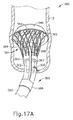
拡大特徴を備えている別の代表的な経口円形アンビル導入システム(300)が、図11〜図17Bに示される。アンビル導入システム(300)は、アンビル(340)と、可撓性チューブ(322)と、スライド特徴(360)と、拡大特徴(361)と、を備える。アンビル(340)は、上述のアンビル(40)と類似している。アンビル(340)は、図15に示されるように、アンビル(340)の近位面(350)に整列されたステープルポケット(352)を備える。アンビル(340)は、また、アンビル(340)の近位面(350)から延在するシャフト(344)を備える。シャフト(344)がアンビル(40)の近位シャフト(42)と類似していることにより、一旦アンビル(340)がステープル留めのために設置されると、シャフト(344)はトロカール(38)と連結するように構成される。アンビル(340)がステープル留めの位置に移動させられるとき、シャフト(344)は可撓性チューブ(322)に連結される。シャフト(344)が可撓性チューブ(322)よりも小さい直径を備えることにより、シャフト(344)は、可撓性チューブ(322)をアンビル(340)に連結するために可撓性チューブ(322)の中にスライドする。シャフト(344)は、また、可撓性チューブ(322)よりも大きい直径を有することにより、シャフト(344)は、可撓性チューブ(322)の周りをスライドし得る。シャフト(344)は、また、シャフト(344)と可撓性チューブ(322)との対応するアパーチャ(312、320)を通して、可撓性チューブ(322)に縫合されてもよい。可撓性チューブ(322)をシャフト(344)に連結する他の好適な方法は、本明細書の教示に基づけば当業者にとって明らかであろう。可撓性チューブ(322)は、従来のNG(経鼻胃)チューブ又は任意の他の好適な構造を備えていてもよい。
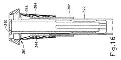
2. Exemplary Expandable Mesh Features Another exemplary oral circular anvil introduction system (300) with expansion features is shown in FIGS. 11-17B. The anvil introduction system (300) includes an anvil (340), a flexible tube (322), a slide feature (360), and an enlarged feature (361). Anvil (340) is similar to the anvil (40) described above. Anvil (340) includes staple pockets (352) aligned with the proximal surface (350) of anvil (340), as shown in FIG. Anvil (340) also includes a shaft (344) extending from the proximal surface (350) of the anvil (340). The shaft (344) is similar to the proximal shaft (42) of the anvil (40), so that once the anvil (340) is installed for stapling, the shaft (344) is connected to the trocar (38). Configured to concatenate. When the anvil (340) is moved to the stapling position, the shaft (344) is coupled to the flexible tube (322). By providing the shaft (344) with a smaller diameter than the flexible tube (322), the shaft (344) allows the flexible tube (322) to connect the flexible tube (322) to the anvil (340). ). The shaft (344) also has a larger diameter than the flexible tube (322) so that the shaft (344) can slide around the flexible tube (322). The shaft (344) may also be sutured to the flexible tube (322) through corresponding apertures (312, 320) of the shaft (344) and the flexible tube (322). Other suitable methods of connecting the flexible tube (322) to the shaft (344) will be apparent to those skilled in the art based on the teachings herein. The flexible tube (322) may comprise a conventional NG (nasogastric) tube or any other suitable structure.
スライド特徴(360)は、可撓性チューブ(322)に連結される。スライド特徴(360)は、図11に示されるように、スライドカラー(368)と、接続部材(367)と、カムカラー(366)と、を備える。スライドカラー(368)が可撓性チューブ(322)の周りを巻くことにより、スライドカラー(368)は、可撓性チューブ(322)に沿って近位及び/又は遠位にスライドする。カムカラー(366)がスライドカラー(368)の遠位に設置され、カムカラー(366)が可撓性チューブ(322)の周りを巻くことにより、カムカラー(366)は、可撓性チューブ(322)に沿って近位及び/又は遠位にスライドする。カムカラー(366)は、テーパー状構成を画定する。1つ以上の接続部材(367)は、スライドカラー(368)とカムカラー(366)との間に延在することにより、スライドカラー(368)をカムカラー(366)に接続する。 The slide feature (360) is coupled to the flexible tube (322). As shown in FIG. 11, the slide feature (360) includes a slide collar (368), a connecting member (367), and a cam collar (366). As the slide collar (368) rolls around the flexible tube (322), the slide collar (368) slides proximally and / or distally along the flexible tube (322). The cam collar (366) is placed distal to the slide collar (368) and the cam collar (366) wraps around the flexible tube (322), thereby causing the cam collar (366) to wrap around the flexible tube (322). Slide proximally and / or distally along. The cam collar (366) defines a tapered configuration. One or more connecting members (367) extend between the slide collar (368) and the cam collar (366) to connect the slide collar (368) to the cam collar (366).
図13〜図14に示されるように、拡大特徴(361)は、また、可撓性チューブ(322)に連結されている。拡大特徴(361)は、拡張部材(362)と、ワッシャー(363)と、を備える。ワッシャー(363)は、ワッシャー(363)がカムカラー(366)とスライドカラー(368)との間に設置されるように、可撓性チューブ(322)の周りを巻いている。ワッシャー(363)は、スライド特徴(360)が、また、ワッシャー(363)に対してスライドするように、可撓性チューブ(322)に対して固定されている。複数の拡張部材(362)が、ワッシャー(363)からアンビル(340)まで遠位に延在する。拡張部材(362)は、図11に示されるように、スライドカラー(368)の下側から、カムカラー(366)を越えて延在するように設置される。メッシュ(364)は、拡張部材(362)を覆うように拡大特徴(361)に適用されている。メッシュ(364)は、アンビル(340)からワッシャー(363)までテーパー状に構成されている。メッシュ(364)は、拡張して拡張部材(362)と接触する。本実施例において、メッシュ(364)は、アンビル(340)の上部の底まで延在する。一部の他の変形例では、メッシュ(364)は、アンビル(340)の上部を完全に包囲する。加えて又は代替において、メッシュ(364)は、アンビル(340)のシャフトを完全に包囲してもよい。 As shown in FIGS. 13-14, the magnification feature (361) is also coupled to the flexible tube (322). The enlargement feature (361) includes an expansion member (362) and a washer (363). The washer (363) is wrapped around the flexible tube (322) such that the washer (363) is placed between the cam collar (366) and the slide collar (368). The washer (363) is secured to the flexible tube (322) such that the slide feature (360) also slides relative to the washer (363). A plurality of expansion members (362) extend distally from the washer (363) to the anvil (340). As shown in FIG. 11, the expansion member (362) is installed so as to extend from the lower side of the slide collar (368) over the cam collar (366). A mesh (364) is applied to the enlarged feature (361) so as to cover the expansion member (362). The mesh (364) is tapered from the anvil (340) to the washer (363). The mesh (364) expands and contacts the expansion member (362). In this example, the mesh (364) extends to the bottom of the top of the anvil (340). In some other variations, the mesh (364) completely surrounds the top of the anvil (340). Additionally or alternatively, the mesh (364) may completely surround the shaft of the anvil (340).
図15〜図16に示されるように、可撓性チューブ(322)は、シャフト(344)を介して、折畳み状態の拡大特徴(361)と共に、アンビル(340)に連結されている。拡張部材(362)及び/又はメッシュ(364)は、図15〜図16の折畳み構成をとるように弾力状態でバイアスをかけられ得る。折畳み状態において、スライド特徴(360)は、カムカラー(366)がワッシャー(363)の遠位にあるように、遠位位置にある。ユーザは、図13〜図14に示されるように、スライド特徴(360)を近位位置まで並進させるためにスライドカラー(368)を把持する。従来の把持装置又は任意の他の装置が、スライドカラー(368)を並進させるために用いられてもよい。スライドカラー(368)が近位に並進するとき、カムカラー(366)も近位に並進してワッシャー(363)を係合する。拡張部材(362)の下側のカムカラー(366)のテーパー状構成は、カムとして作用して、拡張部材(362)を拡張状態にまで外側に押す。拡張状態において、拡張部材(362)は、アンビル(340)の近位面(350)の縁と接触している。メッシュ(364)は、また、拡張部材(362)で拡張する。拡張状態において、拡大特徴(361)は、アンビル(340)の縁及びステープルポケット(352)を覆う。図17Aに示されるように、アンビル(340)の近位面(350)が拡大特徴(361)によって覆われながら、アンビル(240)は、アンビル導入システム(300)の可撓性チューブ(322)を食道を通して引くことによって、経口で導入される。拡大特徴(362)が拡張位置にあるとき、拡大特徴(362)は、アンビル(340)の縁が食道の内壁に沿って引きずられることを防止する。一旦アンビル(340)が食道内の所望の位置に至ると、可撓性チューブ(322)とアンビルシャフト(344)とを接続している縫合糸(380)は切断される。スライドカラー(368)は、次に、遠位に前進させられて、拡大特徴(361)が折り畳まることを可能にする。図17Bに示されるように、可撓性チューブ(322)は、次に、アンビル(340)から可撓性チューブ(322)、スライド特徴(360)、及び拡大特徴(361)を除去するために引かれる。アンビル(340)は、次に、動作のために円形外科用ステープル留め器具(10)のトロカール(38)に連結される。 As shown in FIGS. 15-16, the flexible tube (322) is coupled to the anvil (340) via the shaft (344) with the expanded feature (361) in a folded state. The expansion member (362) and / or the mesh (364) may be biased in a resilient state to take the folded configuration of FIGS. In the folded state, the slide feature (360) is in a distal position such that the cam collar (366) is distal to the washer (363). The user grips the slide collar (368) to translate the slide feature (360) to a proximal position, as shown in FIGS. A conventional gripping device or any other device may be used to translate the slide collar (368). As the slide collar (368) translates proximally, the cam collar (366) also translates proximally to engage the washer (363). The tapered configuration of the lower cam collar (366) of the expansion member (362) acts as a cam and pushes the expansion member (362) outward to the expanded state. In the expanded state, the expansion member (362) is in contact with the edge of the proximal surface (350) of the anvil (340). The mesh (364) is also expanded with an expansion member (362). In the expanded state, the expansion feature (361) covers the edge of the anvil (340) and the staple pocket (352). As shown in FIG. 17A, the anvil (240) is a flexible tube (322) of the anvil introduction system (300) while the proximal surface (350) of the anvil (340) is covered by the enlarged feature (361). Is introduced orally by pulling through the esophagus. When the enlarged feature (362) is in the expanded position, the enlarged feature (362) prevents the edge of the anvil (340) from being dragged along the inner wall of the esophagus. Once the anvil (340) reaches the desired position in the esophagus, the suture (380) connecting the flexible tube (322) and the anvil shaft (344) is severed. The slide collar (368) is then advanced distally to allow the magnification feature (361) to fold. As shown in FIG. 17B, the flexible tube (322) is then removed from the anvil (340) to remove the flexible tube (322), slide feature (360), and enlarged feature (361). Be drawn. The anvil (340) is then coupled to the trocar (38) of the circular surgical stapling instrument (10) for operation.
B.代表的なアンビル把持特徴
アンビル(40)は、アンビル(40)の近位側が組織から離れる方向を向くように、アンビル(40)を逆さまの状態で食道を通して引くことを容易にするアンビル把持特徴を備えていてもよい。これにより、アンビル(40)が食道を通して引かれるとき、アンビル(40)のテーパー状又は湾曲状の上面が組織を係合することが可能になり得る。可撓性又は剛性のアンビル把持特徴が使用され得る。かかる特徴の様々な実施例が以下において更に詳しく記述されるが、一方、他の実施例は、本明細書の教示を考慮すれば当業者にとって明らかであろう。
B. Exemplary Anvil Grip Features The anvil (40) has an anvil grip feature that facilitates pulling the anvil (40) upside down through the esophagus so that the proximal side of the anvil (40) faces away from the tissue. You may have. This may allow the tapered or curved upper surface of the anvil (40) to engage the tissue when the anvil (40) is pulled through the esophagus. A flexible or rigid anvil grip feature can be used. Various embodiments of such features are described in further detail below, while other embodiments will be apparent to those skilled in the art in view of the teachings herein.
1.代表的な可撓性把持特徴
図18〜図19Cは、アンビル把持特徴(448)を備えている代表的なアンビルアセンブリ(400)を示す。把持特徴(448)は、アンビル(440)を、上面(442)が生来の身体管腔(例えば、食道)を通って先導する向きにあるように把持するために使用される。アンビルアセンブリ(400)は、図18に示されるように、アンビル(440)と、アンビル把持特徴(448)と、アンビルシャフト(444)と、を備える。アンビル(440)は、上述のアンビル(40)と類似している。アンビル(440)は、アンビル(440)の下面(450)にステープルポケット(452)を備える。シャフト(444)は、アンビル(440)の下面(450)から延在している。シャフト(444)は、トロカール(38)に連結可能である。アンビル(440)は、上面(442)が下面(450)よりも小さい直径を備えるようなテーパー状構成を画定する。把持特徴(448)は、アンビル(440)の上面(442)から延在している。把持特徴(448)は、可撓性であってもよい。図18に示されるように、把持特徴(448)は、丸いタブとして構成される。把持特徴(448)は、また、長く丸い円筒形タブ、又は平坦なフィン形状のタブとして構成されてもよい。他の好適な把持構成は、本明細書の教示を考慮すれば当業者にとって明らかであろう。
1. Exemplary Flexible Grip Features FIGS. 18-19C illustrate an exemplary anvil assembly (400) that includes an anvil grip feature (448). The grasping feature (448) is used to grasp the anvil (440) such that the top surface (442) is oriented to lead through the native body lumen (eg, esophagus). The anvil assembly (400) includes an anvil (440), an anvil gripping feature (448), and an anvil shaft (444), as shown in FIG. Anvil (440) is similar to anvil (40) described above. The anvil (440) includes a staple pocket (452) on the lower surface (450) of the anvil (440). The shaft (444) extends from the lower surface (450) of the anvil (440). The shaft (444) is connectable to the trocar (38). Anvil (440) defines a tapered configuration such that upper surface (442) has a smaller diameter than lower surface (450). A gripping feature (448) extends from the top surface (442) of the anvil (440). The gripping feature (448) may be flexible. As shown in FIG. 18, the gripping feature (448) is configured as a round tab. The gripping feature (448) may also be configured as a long round cylindrical tab or a flat fin-shaped tab. Other suitable gripping configurations will be apparent to those skilled in the art in view of the teachings herein.
代表的な使用において、図19A〜図19Cに示されるように、アンビル(440)は、先導する上面(442)を食道に経口で通すことによって導入される。アンビル(440)によって画定されたテーパー状構成は、食道を通る円滑な輸送をアンビル(440)に提供する。縫合糸(450)が、アンビル(440)のシャフト(444)の周りに連結される。従来の外科用把持装置(460)は、図19Aに示されるように、把持エンドエフェクタジョー(462)によって把持特徴(448)をつかむために用いられる。把持装置(460)は、次に、アンビル(440)を意図された吻合部位に経口で導入するために食道を通して引かれる。一旦アンビル(440)が食道内の所望の位置に近づくと、把持装置(460)は、把持特徴(448)を解放する。図19Bに示されるように、把持装置(460)は、次に、縫合糸(450)をつかんでアンビルシャフト(444)を引き、それにより、アンビル(440)を反転させて、下面(450)をステープル留めされるべき所望の組織(2)と整列させる。アンビル(440)が反転させられた後に、把持装置(460)は、図19Cに示されるように、アンビル(440)を適所へと引き続ける。縫合糸(350)は、次に、切断され、把持装置(460)は除去される。アンビル(440)は、次に、動作のために円形外科用ステープル留め器具(10)のトロカール(38)に連結される。 In typical use, as shown in FIGS. 19A-19C, anvil (440) is introduced by orally passing the leading upper surface (442) through the esophagus. The tapered configuration defined by the anvil (440) provides smooth transport through the esophagus to the anvil (440). A suture (450) is coupled around the shaft (444) of the anvil (440). A conventional surgical grasping device (460) is used to grasp the grasping feature (448) by the grasping end effector jaw (462), as shown in FIG. 19A. The grasping device (460) is then withdrawn through the esophagus to orally introduce the anvil (440) to the intended anastomosis site. Once the anvil (440) approaches the desired position in the esophagus, the gripping device (460) releases the gripping feature (448). As shown in FIG. 19B, the grasping device (460) then grasps the suture (450) and pulls the anvil shaft (444), thereby inverting the anvil (440) and lower surface (450). Align with the desired tissue (2) to be stapled. After the anvil (440) is flipped, the gripping device (460) continues to pull the anvil (440) into place, as shown in FIG. 19C. The suture (350) is then cut and the grasping device (460) is removed. The anvil (440) is then coupled to the trocar (38) of the circular surgical stapling instrument (10) for operation.
2.代表的な剛性把持特徴
図20〜図21Bは、アンビル把持特徴(748)を備えている別の代表的なアンビルアセンブリ(700)を示す。アンビルアセンブリ(700)は、図20に示されるように、アンビル(740)と、アンビル把持特徴(748)と、を備える。アンビル(740)は、上述のアンビル(40)と類似している。アンビル(740)は、アンビル(740)の下面(750)にステープルポケット(752)を備える。シャフト(746)は、アンビル(740)の上面(742)から延在して、アンビル把持特徴(748)をアンビル(740)に接続している。アンビル把持特徴(748)は、凸面形状の上部を備える。図21Aに示されるように、開口部(744)が、トロカール(738)を受容するために、アンビル(740)の下面(750)に形成されている。開口部(744)は、内側へと延在する環状突出部(743)を備える。
2. Exemplary Rigid Grip Features FIGS. 20-21B illustrate another exemplary anvil assembly (700) that includes an anvil grip feature (748). Anvil assembly (700) comprises an anvil (740) and an anvil gripping feature (748), as shown in FIG. Anvil (740) is similar to anvil (40) described above. Anvil (740) includes staple pockets (752) on the lower surface (750) of anvil (740). The shaft (746) extends from the top surface (742) of the anvil (740) and connects the anvil gripping feature (748) to the anvil (740). The anvil gripping feature (748) comprises a convex top. As shown in FIG. 21A, an opening (744) is formed in the lower surface (750) of the anvil (740) to receive the trocar (738). The opening (744) includes an annular protrusion (743) that extends inwardly.
トロカール(738)は、トロカール(38)と類似している。トロカール(738)は、図21Aに示されるように、尖った遠位端(730)と、カム部分(732)と、シャフト(733)と、拡張部材(736)と、を備える。シャフト(733)の遠位部分は、角度を付けられてカム部分(732)を形成する。尖った遠位端(730)は、カム部分(732)の遠位に設置される。シャフト(733)は、拡張部材(736)を通って延在している。拡張部材(736)は、突出部(743)に対応する内側へと延在する陥凹部(734)を備える。 Trocar (738) is similar to trocar (38). Trocar (738) comprises a pointed distal end (730), a cam portion (732), a shaft (733), and an expansion member (736), as shown in FIG. 21A. The distal portion of shaft (733) is angled to form cam portion (732). A pointed distal end (730) is placed distal to the cam portion (732). The shaft (733) extends through the expansion member (736). The expansion member (736) includes a recess (734) extending inwardly corresponding to the protrusion (743).
代表的な使用において、アンビル(740)は、先導する上面(742)を生来の身体管腔(例えば、食道)を通すことによって導入される。把持装置は、ジョーによって把持特徴(748)をつかんで、アンビル(740)を経口で食道を通して引くために使用される。アンビル(740)は、下面(750)をステープル留めされるべき組織(2)と整列させるために、反転させられる。一旦アンビル(740)が食道内に設置されると、アンビル(740)は動作のためにトロカール(738)に連結される。特に、トロカール(738)は、図21Aに示されるように、陥凹部(734)が突出部(743)と整列するまで、アンビル(740)の開口部(744)の中に挿入される。シャフト(733)は、拡張部材(736)を通してシャフト(733)をスライドさせるために近位に引かれる。シャフト(733)が近位に並進するにつれて、図21Bに示されるように、カム部(732)は、拡張部材(736)を外側に押す。これにより、陥凹部(734)は、突出部(743)を係合させる。拡張部材(736)に対するシャフト(733)の長手方向の位置が固定されることにより、トロカール(738)の陥凹部(734)は、円形外科用ステープル留め器具(10)の動作中、アンビル(740)にトロカール(738)をロックするようにさせる。器具(10)の動作の後に、シャフト(733)は、拡張部材(736)が内側に曲がることを可能にするために、遠位に並進させられ得る。これにより、陥凹部(734)は、突出部(743)から除去されて、トロカール(738)からアンビル(740)のロックを外す。器具(10)及びアンビル(740)は、次に、吻合部位から別々に除去され得る。あるいは、器具(10)は、依然としてアンビル(740)がトロカール(738)に連結された状態のまま、吻合部位から除去されてもよい。 In typical use, the anvil (740) is introduced by passing the leading upper surface (742) through the native body lumen (eg, esophagus). The grasping device is used to grasp the grasping feature (748) by the jaws and pull the anvil (740) orally through the esophagus. The anvil (740) is inverted to align the lower surface (750) with the tissue (2) to be stapled. Once the anvil (740) is installed in the esophagus, the anvil (740) is coupled to the trocar (738) for operation. In particular, trocar (738) is inserted into opening (744) of anvil (740) until recess (734) is aligned with protrusion (743), as shown in FIG. 21A. The shaft (733) is pulled proximally to slide the shaft (733) through the expansion member (736). As shaft (733) translates proximally, cam portion (732) pushes expansion member (736) outward, as shown in FIG. 21B. Thereby, a recessed part (734) engages a protrusion part (743). By fixing the longitudinal position of the shaft (733) relative to the expansion member (736), the recess (734) of the trocar (738) can be secured to the anvil (740) during operation of the circular surgical stapling instrument (10). ) To lock the trocar (738). After operation of the instrument (10), the shaft (733) may be translated distally to allow the expansion member (736) to bend inwardly. This removes the recess (734) from the protrusion (743) and unlocks the anvil (740) from the trocar (738). Instrument (10) and anvil (740) may then be removed separately from the anastomosis site. Alternatively, the instrument (10) may be removed from the anastomosis site while the anvil (740) is still connected to the trocar (738).
C.代表的なアンビル固定特徴
アンビル固定特徴(848)は、上述のようなアンビルを含む様々なアンビルに適用されることにより、アンビル(840)をトロカール(38)に連結している間、組織に対してアンビル(840)を適所に保持し得る。アンビル固定特徴(848)を備えている代表的なアンビルアセンブリ(800)が、図22A〜図22Bに示されている。アンビルアセンブリ(800)は、アンビル(840)と、アンビル固定特徴(820)と、を備える。アンビル(840)は、上述のアンビル(40)と類似している。アンビル(840)は、アンビル(840)の下面(850)にステープルポケット(852)を備える。シャフト(844)は、アンビル(840)の下面(850)から延在している。アンビル固定特徴(848)は、シャフト(844)に固定的に連結されている。アンビル把持特徴(848)は、図22Aに示されるように、カラー(822)と、カラー(822)から延在するフランジ(820)と、を備える。カラー(822)は、シャフト(844)の周りを巻くように構成されることにより、アンビル固定特徴(848)をアンビル(840)に連結する。開口部(824)が、縫合糸が開口部(824)を通過し得るようにフランジ(820)の中に形成される。あるいは、フランジ(820)は、針(832)がフランジ(820)の任意の所望の場所においてフランジ(820)を突き通すことを可能にするために、順応性がある材料で形成されてもよい。
C. Exemplary Anvil Fixing Features Anvil Fixing Features (848) are applied to a variety of anvils, including anvils as described above, so that the anvil (840) is attached to the tissue while connecting it to the trocar (38). Can hold the anvil (840) in place. An exemplary anvil assembly (800) comprising an anvil securing feature (848) is shown in FIGS. 22A-22B. Anvil assembly (800) includes an anvil (840) and an anvil securing feature (820). Anvil (840) is similar to anvil (40) described above. Anvil (840) includes a staple pocket (852) on the lower surface (850) of anvil (840). The shaft (844) extends from the lower surface (850) of the anvil (840). An anvil securing feature (848) is fixedly coupled to shaft (844). The anvil gripping feature (848) comprises a collar (822) and a flange (820) extending from the collar (822), as shown in FIG. 22A. The collar (822) is configured to wrap around the shaft (844), thereby coupling the anvil securing feature (848) to the anvil (840). An opening (824) is formed in the flange (820) so that the suture can pass through the opening (824). Alternatively, the flange (820) may be formed of a compliant material to allow the needle (832) to penetrate the flange (820) at any desired location on the flange (820).
一旦アンビル(840)が上述の特徴のうちの任意のものを使用して、食道を通して内部に設置されると、アンビル固定特徴(848)は、把持装置がアンビル(840)から除去された後に、組織に対してアンビル(840)を保持することを可能にする。図22A〜図22Bに示されるように、組織(2)は、巾着構成で縫合される。縫合糸(830)は、次に、針(832)によってアンビル固定特徴(848)の開口部(824)を通過する。ループが、縫合糸(830)を用いて、フランジ(820)の周囲の開口部(824)を通って形成される。縫合糸(830)は、組織(2)及びフランジ(820)の周囲に引かれ、アンビル(840)は、縫合糸(830)によって適所に保持される。アンビル(840)が組織(2)に固定された状態で、アンビル(840)がトロカール(38)に連結されると、アンビル(840)は適所に保持される。アンビル(840)を維持する他の好適な縫合方法は、本明細書の教示を考慮すれば当業者にとって明らかであろう。 Once the anvil (840) is installed internally through the esophagus using any of the features described above, the anvil fixation feature (848) can be used after the grasping device is removed from the anvil (840). Allows holding anvil (840) to tissue. As shown in FIGS. 22A-22B, tissue (2) is sutured in a purse-string configuration. The suture (830) then passes through the opening (824) of the anvil fixation feature (848) by the needle (832). A loop is formed through the opening (824) around the flange (820) using a suture (830). Suture (830) is pulled around tissue (2) and flange (820), and anvil (840) is held in place by suture (830). When the anvil (840) is coupled to the trocar (38) with the anvil (840) secured to the tissue (2), the anvil (840) is held in place. Other suitable suturing methods for maintaining the anvil (840) will be apparent to those skilled in the art in view of the teachings herein.
III.その他
本明細書で述べる教示、表現、実施形態、実施例などのうちのいずれか1つ又は2つ以上は、本明細書で述べるその他の教示、表現、実施形態、実施例などのいずれか1つ又は2つ以上と組み合わせることができることを理解されたい。上述した教示、表現、実施形態、実施例などはしたがって、互いに対して分離して考慮されるべきではない。本明細書の教示を組み合わせ得る種々の適切な方法が、本明細書の教示を考慮することで、当業者には容易に明らかになるであろう。こうした変更形態及び変形形態は、特許請求の範囲内に含まれるものとする。
III. Others Any one or more of the teachings, expressions, embodiments, examples, etc. described herein may be any one of the other teachings, expressions, embodiments, examples, etc. described herein. It should be understood that one or more than two can be combined. The above-described teachings, expressions, embodiments, examples and the like should therefore not be considered separately from one another. Various suitable ways in which the teachings herein can be combined will be readily apparent to those skilled in the art in view of the teachings herein. Such modifications and variations are intended to be included within the scope of the claims.
本明細書に参照により援用されると言及されたいかなる特許、刊行物、又は他の開示内容も、その全体又は一部において、援用された内容が現行の定義、見解、又は本開示に記載された他の開示内容とあくまで矛盾しない範囲でのみ本明細書に援用されることが認識されるべきである。このように及び必要な範囲で、本明細書に明瞭に記載されている開示は、参照により本明細書に組み込んだ任意の矛盾する事物に取って代わるものとする。本明細書に参照により援用するものとされているが、既存の定義、見解、又は本明細書に記載された他の開示内容と矛盾するすべての内容、又はそれらの部分は、援用された内容と既存の開示内容との間にあくまで矛盾が生じない範囲でのみ援用するものとする。 Any patents, publications, or other disclosures referred to herein by reference are incorporated in their entirety or in part into the current definitions, views, or disclosures. It should be recognized that the disclosure is incorporated herein only to the extent that it does not contradict other disclosures. Thus, to the extent necessary, the disclosure expressly set forth herein shall supersede any conflicting matter incorporated herein by reference. All content, or portions thereof, that is incorporated herein by reference, but that conflicts with existing definitions, views, or other disclosures contained herein, is incorporated by reference. To the extent that there is no discrepancy between the content and the existing disclosure.
上述の装置の変形例は、医療専門家によって行われる従来の治療及び処置での用途だけでなく、ロボット支援された治療及び処置での用途も有することができる。ほんの一例として、本明細書の様々な教示は、ロボットによる外科用システム、例えばIntuitive Surgical,Inc.(Sunnyvale,California)によるDAVINCI(商標)システムに容易に組み込まれ得る。同様に、当業者には明らかとなることであるが、本明細書の様々な教示は、参照によってその開示内容が本明細書に組み込まれる、2004年8月31日公開の米国特許第6,783,524号、名称「超音波焼灼及び切断器具を備えたロボット手術用具(Robotic Surgical Tool with Ultrasound Cauterizing and Cutting Instrument)」の様々な教示と容易に組み合わされ得る。 Variations of the devices described above can have applications in robotic assisted therapy and procedures as well as applications in conventional therapy and procedures performed by medical professionals. By way of example only, the various teachings herein are based on robotic surgical systems such as Intuitive Surgical, Inc. (Sunnyvale, California) can be easily integrated into the DAVINCI ™ system. Similarly, it will be apparent to those skilled in the art that the various teachings herein are disclosed in US Pat. No. 6, published August 31, 2004, the disclosure of which is incorporated herein by reference. No. 783,524, name “Robotic Surgical Tool with Ultrasound Cauterizing and Cutting Instrument” can be easily combined with various teachings.
上述の変形例は、1回の使用後に処分されるように設計されてもよく、あるいは、それらは、複数回使用されるように設計されることもできる。諸形態は、いずれの場合も、少なくとも1回の使用後に再使用のために再調整することができる。再調整することは、装置を分解する工程、それに続いて特定の部品を洗浄又は交換する工程、並びにその後の再組み立て工程の任意の組み合わせを含んでよい。特に、装置の変形物によっては分解されてもよく、また、装置の任意の数の特定の部片又は部品が、任意の組み合わせで選択的に交換されるか、あるいは取り外されてもよい。特定の部品の洗浄及び/又は交換の際、装置の変形物によっては、再調整用の施設で、又は外科的処置の直前にユーザによって、その後の使用のために再組み立てされてよい。装置の再調整では、分解、洗浄/交換、及び再組立のための様々な技術を利用できることが、当業者には理解されよう。このような技術の使用、及びその結果として得られる再調整された装置は、全て、本出願の範囲内にある。 The variants described above may be designed to be disposed of after a single use, or they may be designed to be used multiple times. Forms can be reconditioned for reuse in any case after at least one use. Reconditioning may include any combination of the steps of disassembling the device, followed by cleaning or replacing certain parts, and subsequent reassembly steps. In particular, some variations of the device may be disassembled, and any number of specific pieces or parts of the device may be selectively replaced or removed in any combination. Upon cleaning and / or replacement of particular parts, some device variations may be reassembled for subsequent use either at a reconditioning facility or by the user immediately prior to a surgical procedure. Those skilled in the art will recognize that various techniques for disassembly, cleaning / replacement, and reassembly can be used to recondition the device. The use of such techniques, and the resulting reconditioned device, are all within the scope of this application.
ほんの一例として、本明細書で説明した形態は、処置の前及び/又は後に滅菌してもよい。1つの滅菌技術では、装置は、プラスチック又はTYVEKバッグなど、閉められかつ密閉された容器に入れられる。次いで、容器及び装置は、γ放射線、X線、又は高エネルギー電子など、容器を透過し得る放射線場に置かれてもよい。放射線は、装置上及び容器内の細菌を死滅させることができる。次に、滅菌された装置は、後の使用のために、滅菌した容器内に保管され得る。装置はまた、限定されるものではないが、ベータ若しくはガンマ放射線、エチレンオキシド、又は水蒸気を含め、当該技術分野で既知の任意の他の技術を使用して滅菌されてもよい。 By way of example only, the forms described herein may be sterilized before and / or after treatment. In one sterilization technique, the device is placed in a closed and sealed container, such as a plastic or TYVEK bag. The container and device may then be placed in a radiation field that can penetrate the container, such as gamma radiation, x-rays, or high energy electrons. Radiation can kill bacteria on the device and in the container. The sterilized device can then be stored in a sterilized container for later use. The device may also be sterilized using any other technique known in the art, including but not limited to beta or gamma radiation, ethylene oxide, or water vapor.
本発明の様々な実施形態について図示し説明したが、本明細書で説明した方法及びシステムの更なる改変が、当業者による適切な変更により、本発明の範囲を逸脱することなく達成され得る。そうした可能な変更形態の幾つかについて述べたが、その他の改変も当業者には明らかであろう。例えば、上で議論した例、実施形態、幾何学的形状、材料、寸法、比率、工程などは、代表的なものであり、必須ではない。したがって、本発明の範囲は、以下の特許請求の範囲から考慮されるべきであり、本明細書及び図面に示し説明した構造及び操作の細部に限定されると解釈されるものではない。 While various embodiments of the present invention have been illustrated and described, further modifications of the methods and systems described herein may be achieved by appropriate modifications by those skilled in the art without departing from the scope of the present invention. Although some of such possible variations have been described, other modifications will be apparent to those skilled in the art. For example, the examples, embodiments, geometric shapes, materials, dimensions, ratios, processes, etc. discussed above are representative and not essential. Accordingly, the scope of the present invention should be considered from the following claims, and should not be construed to be limited to the details of construction and operation shown and described herein and in the drawings.
〔実施の態様〕
(1) 組織をステープル留めするための装置であって、前記装置は、
(a)アンビルであって、前記アンビルは、
(i)遠位面と、
(ii)近位面と、
(iii)複数のステープルポケットであって、前記複数のステープルポケットは、前記アンビルの前記近位面に形成されている、複数のステープルポケットと、
を備え、前記アンビルは、身体管腔を通して挿入されるように構成されている、アンビルと、
(b)前記アンビルと連結されているアンビル導入システムであって、前記アンビル導入システムは、拡大特徴を備え、前記拡大特徴は、
(i)折畳み位置と、
(ii)拡張位置であって、前記拡大特徴は、前記拡張位置において前記アンビルの前記ステープルポケットを覆う、拡張位置と、
の間を移行するように構成され、前記拡大特徴は、前記アンビルが前記身体管腔を通して挿入されるとき、前記拡張位置にあるように構成されている、アンビル導入システムと、
を備えている、装置。
(2) 前記アンビルは、経口で挿入されるように構成されている、実施態様1に記載の装置。
(3) 前記アンビル導入システムは、前記アンビルと除去可能に連結されている、実施態様1に記載の装置。
(4) 前記アンビルは、シャフトを更に備えている、実施態様1に記載の装置。
(5) 前記アンビルの前記シャフトに連結されたアンビル固定特徴を更に備え、前記アンビル固定特徴は、前記アンビルを前記身体管腔に固定するように動作可能である、実施態様4に記載の装置。
Embodiment
(1) An apparatus for stapling tissue, the apparatus comprising:
(A) An anvil, wherein the anvil is
(I) a distal surface;
(Ii) a proximal surface;
(Iii) a plurality of staple pockets, wherein the plurality of staple pockets are formed on the proximal surface of the anvil;
The anvil is configured to be inserted through a body lumen; and
(B) An anvil introduction system connected to the anvil, wherein the anvil introduction system includes an enlargement feature,
(I) folding position;
(Ii) an expanded position, wherein the enlarged feature covers the staple pocket of the anvil in the expanded position;
An anvil introduction system configured to transition between and wherein the enlarged feature is configured to be in the expanded position when the anvil is inserted through the body lumen;
Equipped with the device.
(2) The apparatus of embodiment 1, wherein the anvil is configured to be inserted orally.
(3) The apparatus according to embodiment 1, wherein the anvil introduction system is removably connected to the anvil.
(4) The apparatus according to embodiment 1, wherein the anvil further comprises a shaft.
5. The apparatus of embodiment 4, further comprising an anvil fixation feature coupled to the shaft of the anvil, wherein the anvil fixation feature is operable to secure the anvil to the body lumen.
(6) 前記アンビル固定特徴は、前記アンビルの前記シャフトの少なくとも一部分の周りに巻かれたカラーと、前記カラーから外側に突出しているフランジと、を備えている、実施態様5に記載の装置。
(7) 前記アンビル導入システムは、前記アンビルシャフトに連結されたチューブを更に備え、前記チューブは、前記アンビルを前記身体管腔を通して引くように構成されている、実施態様4に記載の装置。
(8) 前記拡大特徴は、テーパー状の構成を画定している、実施態様1に記載の装置。
(9) 前記拡大特徴は、ブラダーを備えている、実施態様1に記載の装置。
(10) 前記ブラダーは、前記ブラダーを前記折畳み位置から前記拡張位置まで移行させるために流体を受容するように構成されている、実施態様9に記載の装置。
6. The apparatus of embodiment 5, wherein the anvil securing feature comprises a collar wound around at least a portion of the shaft of the anvil and a flange projecting outward from the collar.
7. The apparatus of embodiment 4, wherein the anvil introduction system further comprises a tube coupled to the anvil shaft, the tube configured to pull the anvil through the body lumen.
8. The apparatus of embodiment 1, wherein the enlarged feature defines a tapered configuration.
9. The apparatus of embodiment 1, wherein the magnification feature comprises a bladder.
10. The apparatus of embodiment 9, wherein the bladder is configured to receive fluid to move the bladder from the folded position to the extended position.
(11) 前記流体は、空気又は塩類溶液のいずれかである、実施態様10に記載の装置。
(12) 前記拡大特徴は、複数の拡張部材を備えている、実施態様1に記載の装置。
(13) 前記アンビル導入システムは、スライド特徴を更に備え、前記スライド特徴は、前記スライド特徴の並進に反応して、前記拡大特徴を前記折畳み位置から前記拡張位置まで移行させるように動作可能である、実施態様12に記載の装置。
(14) 前記スライド特徴は、スライドカラーと、前記スライドカラーの遠位に設置されたカムカラーと、前記スライドカラーを前記カムカラーに連結する少なくとも1つの接続部材と、を備えている、実施態様13に記載の装置。
(15) 前記拡大特徴は、前記複数の拡張部材の周りに巻かれたメッシュを更に備えている、実施態様13に記載の装置。
(11) The apparatus according to
12. The apparatus of embodiment 1, wherein the expansion feature comprises a plurality of expansion members.
(13) The anvil introduction system further includes a slide feature, the slide feature being operable to move the enlarged feature from the folded position to the extended position in response to translation of the slide feature. Embodiment 13. The device according to
(14) In the thirteenth aspect, the slide feature includes a slide collar, a cam collar installed at a distal end of the slide collar, and at least one connecting member that connects the slide collar to the cam collar. The device described.
15. The apparatus of embodiment 13, wherein the expansion feature further comprises a mesh wound around the plurality of expansion members.
(16) 組織をステープル留めするための装置であって、前記装置は、
(a)アンビルであって、前記アンビルは、
(i)上面と、
(ii)下面と、
(iii)複数のステープルポケットであって、前記複数のステープルポケットは、前記アンビルの前記下面に形成されている、複数のステープルポケットと、
を備え、前記アンビルは、身体管腔を通して挿入されるように構成されている、アンビルと、
(b)前記アンビルに固定されているアンビル把持特徴であって、前記アンビル把持特徴は、前記アンビルの前記上面から外側に延在し、前記把持特徴は、前記アンビルが前記身体管腔を通して引かれるときに前記上面が先導するように、前記アンビルを前記身体管腔を通して引くために把持されるように動作可能である、アンビル把持特徴と、
を備えている、装置。
(17) 前記把持特徴は、可撓性タブを備えている、実施態様16に記載の装置。
(18) 前記把持特徴は、前記アンビルの前記上面から延在するシャフトと、前記シャフトから外側に延在する凸面形状の上部と、を備えている、実施態様16に記載の装置。
(19) 組織をステープル留めするための装置を組織の中に導入するための方法であって、前記装置は、アンビルと、前記アンビルと連結されているアンビル導入システムと、を備え、前記アンビル導入システムは、拡大特徴を備え、前記方法は、
(a)前記アンビル導入システムを前記アンビルに連結することと、
(b)前記アンビル導入システムの前記拡大特徴を拡張位置まで拡張することと、
(c)前記拡大特徴が前記拡張位置にある状態で、前記アンビルを組織を通して所望の位置まで引くことと、を含む、方法。
(20) 外科用ステープル留め器具のトロカールを前記アンビルに連結することを更に含む、実施態様19に記載の方法。
(16) A device for stapling tissue, the device comprising:
(A) An anvil, wherein the anvil is
(I) an upper surface;
(Ii) a lower surface;
(Iii) a plurality of staple pockets, wherein the plurality of staple pockets are formed on the lower surface of the anvil;
The anvil is configured to be inserted through a body lumen; and
(B) an anvil gripping feature secured to the anvil, wherein the anvil gripping feature extends outward from the top surface of the anvil, the gripping feature being pulled through the body lumen An anvil grasping feature operable to be grasped for pulling the anvil through the body lumen, such that the upper surface sometimes leads;
Equipped with the device.
The apparatus of claim 16, wherein the gripping feature comprises a flexible tab.
18. The apparatus of embodiment 16, wherein the gripping feature comprises a shaft extending from the top surface of the anvil and a convex upper portion extending outward from the shaft.
(19) A method for introducing an apparatus for stapling tissue into a tissue, the apparatus comprising: an anvil and an anvil introduction system coupled to the anvil; The system comprises a magnification feature, and the method comprises:
(A) connecting the anvil introduction system to the anvil;
(B) expanding the expansion feature of the anvil introduction system to an expanded position;
(C) pulling the anvil through tissue to a desired position with the magnification feature in the expanded position.
20. The method of embodiment 19, further comprising connecting a trocar of a surgical stapling instrument to the anvil.
Claims (12)
(a)アンビルであって、前記アンビルは、
(i)遠位面と、
(ii)近位面と、
(iii)複数のステープルポケットであって、前記複数のステープルポケットは、前記アンビルの前記近位面に形成されている、複数のステープルポケットと、
を備え、前記アンビルは、身体管腔を通して挿入されるように構成されている、アンビルと、
(b)前記アンビルと連結されているアンビル導入システムであって、前記アンビル導入システムは、拡大特徴を備え、前記拡大特徴は、
(i)折畳み位置と、
(ii)拡張位置であって、前記拡大特徴は、前記拡張位置において前記アンビルの前記ステープルポケットを覆う、拡張位置と、
の間を移行するように構成され、前記拡大特徴は、前記アンビルが前記身体管腔を通して挿入されるとき、前記拡張位置にあるように構成されている、アンビル導入システムと、
を備え、
前記拡大特徴は、ブラダーを備えている、装置。 An apparatus for stapling tissue, the apparatus comprising:
(A) An anvil, wherein the anvil is
(I) a distal surface;
(Ii) a proximal surface;
(Iii) a plurality of staple pockets, wherein the plurality of staple pockets are formed on the proximal surface of the anvil;
The anvil is configured to be inserted through a body lumen; and
(B) An anvil introduction system connected to the anvil, wherein the anvil introduction system includes an enlargement feature,
(I) folding position;
(Ii) an expanded position, wherein the enlarged feature covers the staple pocket of the anvil in the expanded position;
An anvil introduction system configured to transition between and wherein the enlarged feature is configured to be in the expanded position when the anvil is inserted through the body lumen;
With
The enlargement feature comprises a bladder.
(a)アンビルであって、前記アンビルは、
(i)遠位面と、
(ii)近位面と、
(iii)複数のステープルポケットであって、前記複数のステープルポケットは、前記アンビルの前記近位面に形成されている、複数のステープルポケットと、
を備え、前記アンビルは、身体管腔を通して挿入されるように構成されている、アンビルと、
(b)前記アンビルと連結されているアンビル導入システムであって、前記アンビル導入システムは、拡大特徴を備え、前記拡大特徴は、
(i)折畳み位置と、
(ii)拡張位置であって、前記拡大特徴は、前記拡張位置において前記アンビルの前記ステープルポケットを覆う、拡張位置と、
の間を移行するように構成され、前記拡大特徴は、前記アンビルが前記身体管腔を通して挿入されるとき、前記拡張位置にあるように構成されている、アンビル導入システムと、
を備え、
前記拡大特徴は、複数の拡張部材を備え、
前記アンビル導入システムは、スライド特徴を更に備え、前記スライド特徴は、前記スライド特徴の並進に反応して、前記拡大特徴を前記折畳み位置から前記拡張位置まで移行させるように動作可能であり、
前記拡大特徴は、前記複数の拡張部材の周りに巻かれたメッシュを更に備えている、装置。 An apparatus for stapling tissue, the apparatus comprising:
(A) An anvil, wherein the anvil is
(I) a distal surface;
(Ii) a proximal surface;
(Iii) a plurality of staple pockets, wherein the plurality of staple pockets are formed on the proximal surface of the anvil;
The anvil is configured to be inserted through a body lumen; and
(B) An anvil introduction system connected to the anvil, wherein the anvil introduction system includes an enlargement feature,
(I) folding position;
(Ii) an expanded position, wherein the enlarged feature covers the staple pocket of the anvil in the expanded position;
An anvil introduction system configured to transition between and wherein the enlarged feature is configured to be in the expanded position when the anvil is inserted through the body lumen;
With
The expansion characteristics, e Bei a plurality of expansion members,
The anvil introduction system further comprises a slide feature, the slide feature is operable to transition the enlarged feature from the folded position to the extended position in response to translation of the slide feature;
The apparatus, wherein the magnification feature further comprises a mesh wound around the plurality of expansion members .
Applications Claiming Priority (3)
| Application Number | Priority Date | Filing Date | Title |
|---|---|---|---|
| US13/693,430 US9572573B2 (en) | 2012-12-04 | 2012-12-04 | Trans-oral circular anvil introduction system with dilation feature |
| US13/693,430 | 2012-12-04 | ||
| PCT/US2013/073097 WO2014089197A1 (en) | 2012-12-04 | 2013-12-04 | Trans-oral circular anvil introduction system with dilation feature |
Publications (2)
| Publication Number | Publication Date |
|---|---|
| JP2015536224A JP2015536224A (en) | 2015-12-21 |
| JP6373859B2 true JP6373859B2 (en) | 2018-08-15 |
Family
ID=49955476
Family Applications (1)
| Application Number | Title | Priority Date | Filing Date |
|---|---|---|---|
| JP2015545817A Expired - Fee Related JP6373859B2 (en) | 2012-12-04 | 2013-12-04 | Oral circular anvil introduction system with expanded features |
Country Status (9)
| Country | Link |
|---|---|
| US (2) | US9572573B2 (en) |
| EP (1) | EP2928387B1 (en) |
| JP (1) | JP6373859B2 (en) |
| CN (1) | CN104837415B (en) |
| BR (1) | BR112015013062B1 (en) |
| IN (1) | IN2015DN03982A (en) |
| MX (1) | MX357428B (en) |
| RU (1) | RU2655117C2 (en) |
| WO (1) | WO2014089197A1 (en) |
Families Citing this family (72)
| Publication number | Priority date | Publication date | Assignee | Title |
|---|---|---|---|---|
| US7938307B2 (en) * | 2004-10-18 | 2011-05-10 | Tyco Healthcare Group Lp | Support structures and methods of using the same |
| US8360296B2 (en) | 2010-09-09 | 2013-01-29 | Ethicon Endo-Surgery, Inc. | Surgical stapling head assembly with firing lockout for a surgical stapler |
| US8632462B2 (en) | 2011-03-14 | 2014-01-21 | Ethicon Endo-Surgery, Inc. | Trans-rectum universal ports |
| US9572573B2 (en) | 2012-12-04 | 2017-02-21 | Ethicon Endo-Surgery, Llc | Trans-oral circular anvil introduction system with dilation feature |
| US9597081B2 (en) | 2012-12-17 | 2017-03-21 | Ethicon Endo-Surgery, Llc | Motor driven rotary input circular stapler with modular end effector |
| US9445816B2 (en) | 2012-12-17 | 2016-09-20 | Ethicon Endo-Surgery, Llc | Circular stapler with selectable motorized and manual control |
| US20150083772A1 (en) | 2013-09-23 | 2015-03-26 | Ethicon Endo-Surgery, Inc. | Surgical stapler with rotary cam drive and return |
| US10695068B2 (en) | 2017-04-28 | 2020-06-30 | Ethicon Llc | Hysteresis removal feature in surgical stapling instrument |
| US10980542B2 (en) | 2016-11-14 | 2021-04-20 | Ethicon Llc | Circular surgical stapler with recessed deck |
| US10709452B2 (en) | 2013-09-23 | 2020-07-14 | Ethicon Llc | Methods and systems for performing circular stapling |
| US10729444B2 (en) | 2017-04-28 | 2020-08-04 | Ethicon Llc | Liquid-immune trigger circuit for surgical instrument |
| US10478189B2 (en) | 2015-06-26 | 2019-11-19 | Ethicon Llc | Method of applying an annular array of staples to tissue |
| US20180132849A1 (en) | 2016-11-14 | 2018-05-17 | Ethicon Endo-Surgery, Llc | Staple forming pocket configurations for circular surgical stapler anvil |
| US9713469B2 (en) | 2013-09-23 | 2017-07-25 | Ethicon Llc | Surgical stapler with rotary cam drive |
| US9987001B2 (en) | 2015-06-12 | 2018-06-05 | Covidien Lp | Surgical anastomosis apparatus |
| US10307157B2 (en) | 2015-06-26 | 2019-06-04 | Ethicon Llc | Surgical stapler with anvil seating detection |
| US10226253B2 (en) | 2015-06-26 | 2019-03-12 | Ethicon Llc | Firing assembly for circular stapler |
| US10271841B2 (en) | 2015-06-26 | 2019-04-30 | Ethicon Llc | Bailout assembly for surgical stapler |
| US10456134B2 (en) | 2015-06-26 | 2019-10-29 | Ethicon Llc | Surgical stapler with reversible motor |
| US10194911B2 (en) | 2015-06-26 | 2019-02-05 | Ethicon Llc | Surgical stapler with ready state indicator |
| US10905415B2 (en) | 2015-06-26 | 2021-02-02 | Ethicon Llc | Surgical stapler with electromechanical lockout |
| US10271842B2 (en) | 2015-06-26 | 2019-04-30 | Ethicon Llc | Anvil stabilization features for surgical stapler |
| US10517602B2 (en) * | 2015-06-26 | 2019-12-31 | Ethicon Llc | Surgical stapler with reversible polarity |
| US10405855B2 (en) | 2015-06-26 | 2019-09-10 | Ethicon Llc | Firing circuit for surgical stapler |
| US10188386B2 (en) | 2015-06-26 | 2019-01-29 | Ethicon Llc | Surgical stapler with anvil state indicator |
| US10265066B2 (en) | 2015-06-26 | 2019-04-23 | Ethicon Llc | Surgical stapler with incomplete firing indicator |
| US10492790B2 (en) | 2015-09-24 | 2019-12-03 | Ethicon Llc | Apparatus and method for cinching a straight staple line |
| US10499909B2 (en) | 2015-09-24 | 2019-12-10 | Ethicon Llc | Apparatus and method for pleating a bodily lumen |
| US10485548B2 (en) | 2015-09-24 | 2019-11-26 | Ethicon Llc | Apparatus and method for forming a staple line with trocar passageway |
| US10307165B2 (en) | 2015-09-24 | 2019-06-04 | Ethicon Llc | Apparatus and method for radially bunching a bodily lumen |
| US9987013B2 (en) * | 2015-09-24 | 2018-06-05 | Ethicon Llc | Surgical staple buttress with magnetic elements |
| US10542992B2 (en) * | 2015-10-19 | 2020-01-28 | Covidien Lp | Loading unit with stretchable bushing |
| US10307159B2 (en) | 2016-04-01 | 2019-06-04 | Ethicon Llc | Surgical instrument handle assembly with reconfigurable grip portion |
| US11284890B2 (en) | 2016-04-01 | 2022-03-29 | Cilag Gmbh International | Circular stapling system comprising an incisable tissue support |
| US10485542B2 (en) | 2016-04-01 | 2019-11-26 | Ethicon Llc | Surgical stapling instrument comprising multiple lockouts |
| US10682136B2 (en) * | 2016-04-01 | 2020-06-16 | Ethicon Llc | Circular stapling system comprising load control |
| JP6926110B2 (en) * | 2016-04-01 | 2021-08-25 | エシコン エルエルシーEthicon LLC | Surgical staple fastening system with jaw mounting lockout |
| GB201611306D0 (en) | 2016-06-29 | 2016-08-10 | Norwegian Univ Of Science And Tech (Ntnu) | Surgical stapler and a method of stapling tissue |
| US10542981B2 (en) | 2016-11-14 | 2020-01-28 | Ethicon Llc | Atraumatic stapling head features for circular surgical stapler |
| US10603041B2 (en) | 2016-11-14 | 2020-03-31 | Ethicon Llc | Circular surgical stapler with angularly asymmetric deck features |
| US10925607B2 (en) * | 2017-02-28 | 2021-02-23 | Covidien Lp | Surgical stapling apparatus with staple sheath |
| US10835256B2 (en) | 2017-09-27 | 2020-11-17 | Ethicon Llc | Circular stapling instrument with firing trigger having integral resilient features |
| US11039839B2 (en) | 2017-09-27 | 2021-06-22 | Cilag Gmbh International | Circular stapling instrument with unitary closure rod |
| US10751059B2 (en) | 2017-09-27 | 2020-08-25 | Ethicon Llc | Circular stapling instrument anvil with shank having unitary latches with living hinge |
| US10758236B2 (en) | 2017-09-27 | 2020-09-01 | Ethicon Llc | Circular stapling instrument with torque limiting feature |
| US11058428B2 (en) | 2017-09-27 | 2021-07-13 | Cilag Gmbh International | Circular stapling instrument with asymmetric molded shroud components |
| US11589871B2 (en) * | 2017-11-10 | 2023-02-28 | Cilag Gmbh International | Laparoscopic stapler with flippable housing assembly and flippable anvil assembly |
| CN108186068A (en) * | 2017-12-20 | 2018-06-22 | 西人马(厦门)科技有限公司 | The intelligent stapler of body temperature can be perceived |
| CN108186069A (en) * | 2017-12-20 | 2018-06-22 | 西人马(厦门)科技有限公司 | Plug-in conducting connecting part and visual intelligent stapler |
| US20190201034A1 (en) * | 2017-12-28 | 2019-07-04 | Ethicon Llc | Powered stapling device configured to adjust force, advancement speed, and overall stroke of cutting member based on sensed parameter of firing or clamping |
| CN108175465A (en) * | 2018-01-10 | 2018-06-19 | 苏州贝诺医疗器械有限公司 | A kind of tube type anastomat |
| BR102019003934A2 (en) | 2018-03-07 | 2019-09-17 | Ethicon Llc | SURGICAL STAPLER WITH REVERSIBLE POLARITY |
| US10595873B2 (en) * | 2018-04-19 | 2020-03-24 | Franklin Institute of Innovation, LLC | Surgical staplers and related methods |
| USD893719S1 (en) * | 2018-05-16 | 2020-08-18 | Ethicon Llc | Surgical stapler |
| USD893718S1 (en) * | 2018-05-16 | 2020-08-18 | Ethicon Llc | Surgical stapler |
| USD905242S1 (en) * | 2018-05-16 | 2020-12-15 | Ethicon Llc | Surgical stapler |
| USD893721S1 (en) * | 2018-05-16 | 2020-08-18 | Ethicon Llc | Surgical stapler |
| USD896962S1 (en) * | 2018-05-16 | 2020-09-22 | Ethicon Llc | Surgical stapler |
| USD893720S1 (en) * | 2018-05-16 | 2020-08-18 | Ethicon Llc | Surgical stapler |
| US11051819B2 (en) | 2018-10-15 | 2021-07-06 | Cilag Gmbh International | Latch to prevent back-driving of circular surgical stapler |
| US11207071B2 (en) | 2018-10-15 | 2021-12-28 | Cilag Gmbh International | Dual stage closure system for circular surgical stapler |
| US11134952B2 (en) | 2018-10-15 | 2021-10-05 | Cilag Gmbh International | Dual lever to reduce force to fire in circular surgical stapler |
| US11701109B2 (en) | 2018-12-28 | 2023-07-18 | Cilag Gmbh International | Surgical stapler with sloped staple deck for varying tissue compression |
| US11504127B2 (en) * | 2019-01-08 | 2022-11-22 | Olympus Corporation | Method for anastomosing alimentary tract |
| US11147559B2 (en) | 2019-03-08 | 2021-10-19 | Cilag Gmbh International | Staple height indicator for powered surgical stapler |
| US11224432B2 (en) | 2019-03-08 | 2022-01-18 | Cilag Gmbh International | Timer circuit to control firing of powered surgical stapler |
| US11116508B2 (en) | 2019-03-08 | 2021-09-14 | Cilag Gmbh International | Electrical potential shifting circuit for powered surgical stapler |
| US12082817B2 (en) | 2019-03-08 | 2024-09-10 | Cilag Gmbh International | Power control circuit for powered surgical stapler |
| US11123075B2 (en) | 2019-03-08 | 2021-09-21 | Cilag Gmbh International | Circular surgical stapler |
| US11185324B2 (en) * | 2019-09-18 | 2021-11-30 | Cilag Gmbh International | Anvil retention and release features for powered circular surgical stapler |
| RU2740427C1 (en) * | 2020-04-03 | 2021-01-14 | Артем Александрович Махалов | Method for extraperitoneal ligation of vaginal process of peritoneum under ultrasound control in congenital inguinal hernias, hydrocele and spermatic cord hydrocyst in children and instrument for implementation thereof |
| US20240225652A1 (en) * | 2021-06-09 | 2024-07-11 | Covidien Lp | Retractable trocar for circular stapling instruments |
Family Cites Families (47)
| Publication number | Priority date | Publication date | Assignee | Title |
|---|---|---|---|---|
| DE2947107A1 (en) | 1978-12-07 | 1980-06-26 | United States Surgical Corp | ACCURATELY ALIGNED CARTRIDGE AND INSTRUMENT FOR CLAMPING ANASTOMOSES |
| SU1235495A1 (en) * | 1980-12-29 | 1986-06-07 | Всесоюзный научно-исследовательский и испытательный институт медицинской техники | Apparatus for placing compression anastomoses |
| US4817847A (en) | 1986-04-21 | 1989-04-04 | Finanzaktiengesellschaft Globe Control | Instrument and a procedure for performing an anastomosis |
| US4873977A (en) * | 1987-02-11 | 1989-10-17 | Odis L. Avant | Stapling method and apparatus for vesicle-urethral re-anastomosis following retropubic prostatectomy and other tubular anastomosis |
| DE8714082U1 (en) | 1987-04-21 | 1988-02-18 | United States Surgical Corp., Norwalk, Conn. | Mushroom-shaped anvil for a surgical stapler |
| US5285944A (en) * | 1987-05-26 | 1994-02-15 | United States Surgical Corporation | Surgical stapler apparatus |
| US4805823A (en) | 1988-03-18 | 1989-02-21 | Ethicon, Inc. | Pocket configuration for internal organ staplers |
| US5350104A (en) | 1991-08-23 | 1994-09-27 | Ethicon, Inc. | Sealing means for endoscopic surgical anastomosis stapling instrument |
| US5333773A (en) | 1991-08-23 | 1994-08-02 | Ethicon, Inc. | Sealing means for endoscopic surgical anastomosis stapling instrument |
| GR920100358A (en) | 1991-08-23 | 1993-06-07 | Ethicon Inc | Surgical anastomosis stapling instrument. |
| US5314435A (en) * | 1992-05-19 | 1994-05-24 | United States Surgical Corporation | Anvil delivery system |
| US5360154A (en) * | 1992-07-17 | 1994-11-01 | United States Surgical Corporation | Apparatus for creating partial anastomoses |
| US5415334A (en) | 1993-05-05 | 1995-05-16 | Ethicon Endo-Surgery | Surgical stapler and staple cartridge |
| US5597107A (en) | 1994-02-03 | 1997-01-28 | Ethicon Endo-Surgery, Inc. | Surgical stapler instrument |
| US5465895A (en) | 1994-02-03 | 1995-11-14 | Ethicon Endo-Surgery, Inc. | Surgical stapler instrument |
| US5632432A (en) | 1994-12-19 | 1997-05-27 | Ethicon Endo-Surgery, Inc. | Surgical instrument |
| US5704534A (en) | 1994-12-19 | 1998-01-06 | Ethicon Endo-Surgery, Inc. | Articulation assembly for surgical instruments |
| US5814055A (en) | 1995-09-19 | 1998-09-29 | Ethicon Endo-Surgery, Inc. | Surgical clamping mechanism |
| US5836503A (en) * | 1996-04-22 | 1998-11-17 | United States Surgical Corporation | Insertion device for surgical apparatus |
| JPH114832A (en) | 1997-06-18 | 1999-01-12 | Nissho Corp | Auxiliary tool of automatic digestive tract anastomosing device |
| US6623494B1 (en) * | 1999-04-16 | 2003-09-23 | Integrated Vascular Interventional Technologies, L.C. (Ivit, Lc) | Methods and systems for intraluminally directed vascular anastomosis |
| CA2402313C (en) * | 2000-03-06 | 2009-03-03 | Tyco Healthcare Group Lp | Apparatus and method for performing a bypass procedure in a digestive system |
| US6783524B2 (en) | 2001-04-19 | 2004-08-31 | Intuitive Surgical, Inc. | Robotic surgical tool with ultrasound cauterizing and cutting instrument |
| US7380696B2 (en) | 2003-05-20 | 2008-06-03 | Ethicon Endo-Surgery, Inc. | Articulating surgical stapling instrument incorporating a two-piece E-beam firing mechanism |
| US7380695B2 (en) | 2003-05-20 | 2008-06-03 | Ethicon Endo-Surgery, Inc. | Surgical stapling instrument having a single lockout mechanism for prevention of firing |
| US7143923B2 (en) | 2003-05-20 | 2006-12-05 | Ethicon Endo-Surgery, Inc. | Surgical stapling instrument having a firing lockout for an unclosed anvil |
| US6978921B2 (en) | 2003-05-20 | 2005-12-27 | Ethicon Endo-Surgery, Inc. | Surgical stapling instrument incorporating an E-beam firing mechanism |
| US7434715B2 (en) | 2003-09-29 | 2008-10-14 | Ethicon Endo-Surgery, Inc. | Surgical stapling instrument having multistroke firing with opening lockout |
| US7303108B2 (en) | 2003-09-29 | 2007-12-04 | Ethicon Endo-Surgery, Inc. | Surgical stapling instrument incorporating a multi-stroke firing mechanism with a flexible rack |
| US7309341B2 (en) * | 2003-09-30 | 2007-12-18 | Ethicon Endo-Surgery, Inc. | Single lumen anastomosis applier for self-deploying fastener |
| EP1588667A1 (en) * | 2004-04-20 | 2005-10-26 | Polyganics B.V. | Devices for anastomosis |
| US7367485B2 (en) | 2004-06-30 | 2008-05-06 | Ethicon Endo-Surgery, Inc. | Surgical stapling instrument incorporating a multistroke firing mechanism having a rotary transmission |
| US7845536B2 (en) | 2004-10-18 | 2010-12-07 | Tyco Healthcare Group Lp | Annular adhesive structure |
| AU2005295477B2 (en) | 2004-10-18 | 2011-11-24 | Covidien Lp | Structure for applying sprayable wound treatment material |
| US20060201989A1 (en) * | 2005-03-11 | 2006-09-14 | Ojeda Herminio F | Surgical anvil and system for deploying the same |
| CA2616713A1 (en) * | 2005-07-25 | 2007-02-01 | Endogun Medical Systems Ltd. | Anastomosis device and system |
| US8579176B2 (en) | 2005-07-26 | 2013-11-12 | Ethicon Endo-Surgery, Inc. | Surgical stapling and cutting device and method for using the device |
| US7721930B2 (en) | 2006-11-10 | 2010-05-25 | Thicon Endo-Surgery, Inc. | Disposable cartridge with adhesive for use with a stapling device |
| WO2008089404A2 (en) | 2007-01-19 | 2008-07-24 | Synovis Life Technologies, Inc. | Circular stapler anvil introducer |
| US9597080B2 (en) * | 2007-09-24 | 2017-03-21 | Covidien Lp | Insertion shroud for surgical instrument |
| US8770460B2 (en) * | 2008-12-23 | 2014-07-08 | George E. Belzer | Shield for surgical stapler and method of use |
| US8622275B2 (en) * | 2009-11-19 | 2014-01-07 | Ethicon Endo-Surgery, Inc. | Circular stapler introducer with rigid distal end portion |
| JP2011224031A (en) * | 2010-04-15 | 2011-11-10 | Fujifilm Corp | Anastomosis apparatus, endoscope system, and method of controlling anastomosis apparatus |
| US9572573B2 (en) * | 2012-12-04 | 2017-02-21 | Ethicon Endo-Surgery, Llc | Trans-oral circular anvil introduction system with dilation feature |
| US9522002B2 (en) * | 2012-12-13 | 2016-12-20 | Covidien Lp | Surgical instrument with pressure distribution device |
| US10172622B2 (en) * | 2015-05-01 | 2019-01-08 | Jill Kelley | Applicator instrument with folding stapling tip |
| US9717515B1 (en) * | 2015-08-10 | 2017-08-01 | MW Support Services, LLC | Medical device for sleeve gastrectomy surgery |
-
2012
- 2012-12-04 US US13/693,430 patent/US9572573B2/en active Active
-
2013
- 2013-12-04 EP EP13821008.3A patent/EP2928387B1/en active Active
- 2013-12-04 IN IN3982DEN2015 patent/IN2015DN03982A/en unknown
- 2013-12-04 JP JP2015545817A patent/JP6373859B2/en not_active Expired - Fee Related
- 2013-12-04 CN CN201380063907.6A patent/CN104837415B/en active Active
- 2013-12-04 MX MX2015007040A patent/MX357428B/en active IP Right Grant
- 2013-12-04 BR BR112015013062-3A patent/BR112015013062B1/en active IP Right Grant
- 2013-12-04 WO PCT/US2013/073097 patent/WO2014089197A1/en active Application Filing
- 2013-12-04 RU RU2015126850A patent/RU2655117C2/en not_active IP Right Cessation
-
2016
- 2016-07-20 US US15/214,839 patent/US10743866B2/en active Active
Also Published As
| Publication number | Publication date |
|---|---|
| MX2015007040A (en) | 2015-09-28 |
| US20160324525A1 (en) | 2016-11-10 |
| BR112015013062B1 (en) | 2021-08-31 |
| EP2928387B1 (en) | 2017-11-22 |
| US10743866B2 (en) | 2020-08-18 |
| RU2655117C2 (en) | 2018-05-23 |
| US20140151429A1 (en) | 2014-06-05 |
| WO2014089197A1 (en) | 2014-06-12 |
| US9572573B2 (en) | 2017-02-21 |
| RU2015126850A (en) | 2017-01-11 |
| BR112015013062A2 (en) | 2017-07-11 |
| MX357428B (en) | 2018-07-09 |
| CN104837415A (en) | 2015-08-12 |
| JP2015536224A (en) | 2015-12-21 |
| EP2928387A1 (en) | 2015-10-14 |
| IN2015DN03982A (en) | 2015-10-02 |
| CN104837415B (en) | 2017-09-12 |
Similar Documents
| Publication | Publication Date | Title |
|---|---|---|
| JP6373859B2 (en) | Oral circular anvil introduction system with expanded features | |
| US11701120B2 (en) | Circular anvil introduction system with alignment feature | |
| US11690625B2 (en) | Pivoting anvil for surgical circular stapler | |
| JP6297585B2 (en) | Surgical stapler having staple widths varying along different perimeters | |
| US9597082B2 (en) | Method and apparatus for sealing end-to-end anastomosis | |
| EP3146910B1 (en) | Apparatus for forming a staple line with trocar passageway | |
| WO2017053354A2 (en) | Apparatus and method for radially bunching a bodily lumen | |
| JP7271524B2 (en) | Circular stapling instrument with asymmetrically molded shroud component |
Legal Events
| Date | Code | Title | Description |
|---|---|---|---|
| A621 | Written request for application examination |
Free format text: JAPANESE INTERMEDIATE CODE: A621 Effective date: 20161025 |
|
| A131 | Notification of reasons for refusal |
Free format text: JAPANESE INTERMEDIATE CODE: A131 Effective date: 20170718 |
|
| A977 | Report on retrieval |
Free format text: JAPANESE INTERMEDIATE CODE: A971007 Effective date: 20170721 |
|
| A521 | Request for written amendment filed |
Free format text: JAPANESE INTERMEDIATE CODE: A523 Effective date: 20171006 |
|
| A131 | Notification of reasons for refusal |
Free format text: JAPANESE INTERMEDIATE CODE: A131 Effective date: 20180313 |
|
| A521 | Request for written amendment filed |
Free format text: JAPANESE INTERMEDIATE CODE: A523 Effective date: 20180528 |
|
| TRDD | Decision of grant or rejection written | ||
| A01 | Written decision to grant a patent or to grant a registration (utility model) |
Free format text: JAPANESE INTERMEDIATE CODE: A01 Effective date: 20180619 |
|
| A61 | First payment of annual fees (during grant procedure) |
Free format text: JAPANESE INTERMEDIATE CODE: A61 Effective date: 20180718 |
|
| R150 | Certificate of patent or registration of utility model |
Ref document number: 6373859 Country of ref document: JP Free format text: JAPANESE INTERMEDIATE CODE: R150 |
|
| R250 | Receipt of annual fees |
Free format text: JAPANESE INTERMEDIATE CODE: R250 |
|
| R250 | Receipt of annual fees |
Free format text: JAPANESE INTERMEDIATE CODE: R250 |
|
| LAPS | Cancellation because of no payment of annual fees |