JP6369876B2 - Lighting device connector having a heat sink - Google Patents
Lighting device connector having a heat sink Download PDFInfo
- Publication number
- JP6369876B2 JP6369876B2 JP2016520005A JP2016520005A JP6369876B2 JP 6369876 B2 JP6369876 B2 JP 6369876B2 JP 2016520005 A JP2016520005 A JP 2016520005A JP 2016520005 A JP2016520005 A JP 2016520005A JP 6369876 B2 JP6369876 B2 JP 6369876B2
- Authority
- JP
- Japan
- Prior art keywords
- connector plug
- lighting device
- heat
- connector
- interface
- Prior art date
- Legal status (The legal status is an assumption and is not a legal conclusion. Google has not performed a legal analysis and makes no representation as to the accuracy of the status listed.)
- Active
Links
Images


Classifications
-
- H—ELECTRICITY
- H01—ELECTRIC ELEMENTS
- H01R—ELECTRICALLY-CONDUCTIVE CONNECTIONS; STRUCTURAL ASSOCIATIONS OF A PLURALITY OF MUTUALLY-INSULATED ELECTRICAL CONNECTING ELEMENTS; COUPLING DEVICES; CURRENT COLLECTORS
- H01R13/00—Details of coupling devices of the kinds covered by groups H01R12/70 or H01R24/00 - H01R33/00
- H01R13/66—Structural association with built-in electrical component
- H01R13/717—Structural association with built-in electrical component with built-in light source
- H01R13/7175—Light emitting diodes (LEDs)
-
- F—MECHANICAL ENGINEERING; LIGHTING; HEATING; WEAPONS; BLASTING
- F21—LIGHTING
- F21V—FUNCTIONAL FEATURES OR DETAILS OF LIGHTING DEVICES OR SYSTEMS THEREOF; STRUCTURAL COMBINATIONS OF LIGHTING DEVICES WITH OTHER ARTICLES, NOT OTHERWISE PROVIDED FOR
- F21V23/00—Arrangement of electric circuit elements in or on lighting devices
- F21V23/06—Arrangement of electric circuit elements in or on lighting devices the elements being coupling devices, e.g. connectors
-
- F—MECHANICAL ENGINEERING; LIGHTING; HEATING; WEAPONS; BLASTING
- F21—LIGHTING
- F21V—FUNCTIONAL FEATURES OR DETAILS OF LIGHTING DEVICES OR SYSTEMS THEREOF; STRUCTURAL COMBINATIONS OF LIGHTING DEVICES WITH OTHER ARTICLES, NOT OTHERWISE PROVIDED FOR
- F21V29/00—Protecting lighting devices from thermal damage; Cooling or heating arrangements specially adapted for lighting devices or systems
- F21V29/50—Cooling arrangements
- F21V29/70—Cooling arrangements characterised by passive heat-dissipating elements, e.g. heat-sinks
-
- G—PHYSICS
- G06—COMPUTING; CALCULATING OR COUNTING
- G06F—ELECTRIC DIGITAL DATA PROCESSING
- G06F1/00—Details not covered by groups G06F3/00 - G06F13/00 and G06F21/00
- G06F1/16—Constructional details or arrangements
- G06F1/20—Cooling means
-
- H—ELECTRICITY
- H01—ELECTRIC ELEMENTS
- H01R—ELECTRICALLY-CONDUCTIVE CONNECTIONS; STRUCTURAL ASSOCIATIONS OF A PLURALITY OF MUTUALLY-INSULATED ELECTRICAL CONNECTING ELEMENTS; COUPLING DEVICES; CURRENT COLLECTORS
- H01R13/00—Details of coupling devices of the kinds covered by groups H01R12/70 or H01R24/00 - H01R33/00
- H01R13/62—Means for facilitating engagement or disengagement of coupling parts or for holding them in engagement
- H01R13/629—Additional means for facilitating engagement or disengagement of coupling parts, e.g. aligning or guiding means, levers, gas pressure electrical locking indicators, manufacturing tolerances
- H01R13/631—Additional means for facilitating engagement or disengagement of coupling parts, e.g. aligning or guiding means, levers, gas pressure electrical locking indicators, manufacturing tolerances for engagement only
-
- H—ELECTRICITY
- H01—ELECTRIC ELEMENTS
- H01R—ELECTRICALLY-CONDUCTIVE CONNECTIONS; STRUCTURAL ASSOCIATIONS OF A PLURALITY OF MUTUALLY-INSULATED ELECTRICAL CONNECTING ELEMENTS; COUPLING DEVICES; CURRENT COLLECTORS
- H01R24/00—Two-part coupling devices, or either of their cooperating parts, characterised by their overall structure
- H01R24/20—Coupling parts carrying sockets, clips or analogous contacts and secured only to wire or cable
-
- H—ELECTRICITY
- H01—ELECTRIC ELEMENTS
- H01R—ELECTRICALLY-CONDUCTIVE CONNECTIONS; STRUCTURAL ASSOCIATIONS OF A PLURALITY OF MUTUALLY-INSULATED ELECTRICAL CONNECTING ELEMENTS; COUPLING DEVICES; CURRENT COLLECTORS
- H01R24/00—Two-part coupling devices, or either of their cooperating parts, characterised by their overall structure
- H01R24/60—Contacts spaced along planar side wall transverse to longitudinal axis of engagement
- H01R24/62—Sliding engagements with one side only, e.g. modular jack coupling devices
-
- F—MECHANICAL ENGINEERING; LIGHTING; HEATING; WEAPONS; BLASTING
- F21—LIGHTING
- F21Y—INDEXING SCHEME ASSOCIATED WITH SUBCLASSES F21K, F21L, F21S and F21V, RELATING TO THE FORM OR THE KIND OF THE LIGHT SOURCES OR OF THE COLOUR OF THE LIGHT EMITTED
- F21Y2101/00—Point-like light sources
-
- F—MECHANICAL ENGINEERING; LIGHTING; HEATING; WEAPONS; BLASTING
- F21—LIGHTING
- F21Y—INDEXING SCHEME ASSOCIATED WITH SUBCLASSES F21K, F21L, F21S and F21V, RELATING TO THE FORM OR THE KIND OF THE LIGHT SOURCES OR OF THE COLOUR OF THE LIGHT EMITTED
- F21Y2115/00—Light-generating elements of semiconductor light sources
- F21Y2115/10—Light-emitting diodes [LED]
-
- H—ELECTRICITY
- H01—ELECTRIC ELEMENTS
- H01R—ELECTRICALLY-CONDUCTIVE CONNECTIONS; STRUCTURAL ASSOCIATIONS OF A PLURALITY OF MUTUALLY-INSULATED ELECTRICAL CONNECTING ELEMENTS; COUPLING DEVICES; CURRENT COLLECTORS
- H01R13/00—Details of coupling devices of the kinds covered by groups H01R12/70 or H01R24/00 - H01R33/00
- H01R13/46—Bases; Cases
- H01R13/502—Bases; Cases composed of different pieces
- H01R13/506—Bases; Cases composed of different pieces assembled by snap action of the parts
-
- H—ELECTRICITY
- H01—ELECTRIC ELEMENTS
- H01R—ELECTRICALLY-CONDUCTIVE CONNECTIONS; STRUCTURAL ASSOCIATIONS OF A PLURALITY OF MUTUALLY-INSULATED ELECTRICAL CONNECTING ELEMENTS; COUPLING DEVICES; CURRENT COLLECTORS
- H01R2107/00—Four or more poles
-
- H—ELECTRICITY
- H01—ELECTRIC ELEMENTS
- H01R—ELECTRICALLY-CONDUCTIVE CONNECTIONS; STRUCTURAL ASSOCIATIONS OF A PLURALITY OF MUTUALLY-INSULATED ELECTRICAL CONNECTING ELEMENTS; COUPLING DEVICES; CURRENT COLLECTORS
- H01R33/00—Coupling devices specially adapted for supporting apparatus and having one part acting as a holder providing support and electrical connection via a counterpart which is structurally associated with the apparatus, e.g. lamp holders; Separate parts thereof
- H01R33/05—Two-pole devices
- H01R33/06—Two-pole devices with two current-carrying pins, blades or analogous contacts, having their axes parallel to each other
- H01R33/08—Two-pole devices with two current-carrying pins, blades or analogous contacts, having their axes parallel to each other for supporting tubular fluorescent lamp
- H01R33/0836—Two-pole devices with two current-carrying pins, blades or analogous contacts, having their axes parallel to each other for supporting tubular fluorescent lamp characterised by the lamp holding means
Description
本発明は、一般には、照明器具又は光モジュールのような、照明装置に電力を供給するためのコネクタプラグの分野に関する。 The present invention relates generally to the field of connector plugs for supplying power to lighting devices, such as lighting fixtures or light modules.
照明器具又は照明モジュールのような、照明装置のための、ソケットのような、コネクタ装置には、前記照明装置を支持する及び前記照明装置に電力を供給する目的を有する。ソケットは、前記照明装置を前記ソケットに機械的に結合するための固定配置、及び前記照明装置に電力を供給するための電子接点を有する。これに応じて、照明装置は、固定配置及び電子接点は、前記ソケットの前記固定配置及び電子接点と嵌合するために適応化された固定配置及び電子接点を有する。通常、ソケットは標準化されており、異なる製造者の照明装置及びソケットの嵌合を可能にする。標準的なソケット配置は、例えば、ネジ型ソケット及び2ピン型(bi-pin type)ソケットを含む。 A connector device, such as a socket, for a lighting device, such as a lighting fixture or a lighting module, has the purpose of supporting the lighting device and supplying power to the lighting device. The socket has a fixed arrangement for mechanically coupling the lighting device to the socket and electronic contacts for supplying power to the lighting device. Accordingly, the lighting device has a fixed arrangement and an electronic contact adapted for mating with the fixed arrangement and the electronic contact of the socket. Normally, sockets are standardized and allow for fitting of lighting devices and sockets from different manufacturers. Standard socket arrangements include, for example, screw-type sockets and bi-pin type sockets.
現代の照明装置の技術、例えば固体(例えば発光ダイオード、LED)ベースの照明装置は、しばしば、前記照明装置のより長い寿命を促進するための冷却を必要とする。通常、このような技術に基づく照明装置は、前記照明装置からの熱の放散のためのヒートシンクを有する。しかしながら、このようなヒートシンクは、時々、前記照明装置からの許容可能な熱放散を達成するのに十分なものではないことがあり、特に、G4及びG9型のLEDベースの照明装置のような、前記照明装置の小さい寸法により限られた熱放散面を有する比較的小さいLEDベースの照明装置の場合であり得る。 Modern lighting device technologies, such as solid state (eg, light emitting diode, LED) based lighting devices, often require cooling to promote a longer life of the lighting device. Typically, lighting devices based on such techniques have a heat sink for the dissipation of heat from the lighting device. However, such heat sinks may sometimes not be sufficient to achieve acceptable heat dissipation from the luminaire, especially like G4 and G9 type LED-based luminaires, This may be the case for a relatively small LED-based lighting device having a heat dissipation surface limited by the small dimensions of the lighting device.
上述の不利な点を克服する又は少なくとも軽減するコネクタ装置及び照明装置を達成することが有利であり得る。特に、従来技術と比較して照明装置のための代替的なコネクタ装置を使用可能にすることが望ましい。更に、前記照明装置からの熱放散を向上させる照明装置のためのコネクタ装置を使用可能にすることが望ましい。 It may be advantageous to achieve a connector device and lighting device that overcomes or at least mitigates the above disadvantages. In particular, it is desirable to be able to use an alternative connector device for a lighting device compared to the prior art. Furthermore, it is desirable to be able to use a connector device for a lighting device that improves heat dissipation from the lighting device.
これらの懸案事項の1つ以上に良好に対処するために、添付の独立請求項に規定されるフィーチャを有するコネクタプラグ及び照明装置が、提供される。好ましい実施例は、添付の従属請求項に規定される。 In order to better address one or more of these concerns, connector plugs and lighting devices are provided having the features defined in the accompanying independent claims. Preferred embodiments are defined in the appended dependent claims.
従って、1つの見地によれば、照明装置のためのコネクタプラグが提供される。前記コネクタプラグは、前記照明装置を前記コネクタプラグに機械的に結合させるための固定配置と、前記コネクタプラグに結合された前記照明装置に電力を輸送する及び前記コネクタプラグに結合された前記照明装置とデータを通信するように配された電子接点とを有する。更に、前記コネクタプラグは、前記コネクタプラグに結合されている前記照明装置からの熱を受容する熱受容インターフェースと、前記熱受容インターフェースを介して受け取られた熱の少なくとも一部を放散させる熱放散インターフェースとを持つヒートシンクを有する。 Thus, according to one aspect, a connector plug for a lighting device is provided. The connector plug has a fixed arrangement for mechanically coupling the lighting device to the connector plug, and transports electric power to the lighting device coupled to the connector plug, and the lighting device coupled to the connector plug. And electronic contacts arranged to communicate data. The connector plug further includes a heat receiving interface that receives heat from the lighting device coupled to the connector plug, and a heat dissipation interface that dissipates at least a portion of the heat received through the heat receiving interface. And have a heat sink.
更なる見地によれば、先の見地において規定されたコネクタプラグに対する結合のための照明装置が提供される。前記照明装置は、前記照明装置を前記コネクタプラグに機械的に結合させる固定配置を有するコネクタ・ポート配置と、前記コネクタプラグから電力を受け取る及び前記コネクタプラグとデータを通信する電子接点とを有する。更に、前記コネクタ・ポート配置は、前記照明装置により生成される熱を前記コネクタプラグに輸送する熱放散インターフェースを有する。従って、前記コネクタプラグは、前記照明装置の前記コネクタ・ポート配置内に挿入可能であっても良い。 According to a further aspect, an illuminating device for coupling to a connector plug as defined in the previous aspect is provided. The lighting device includes a connector port arrangement having a fixed arrangement that mechanically couples the lighting device to the connector plug, and electronic contacts that receive power from the connector plug and communicate data with the connector plug. Furthermore, the connector port arrangement has a heat dissipation interface that transports heat generated by the lighting device to the connector plug. Accordingly, the connector plug may be insertable into the connector / port arrangement of the lighting device.
本見地は、前記照明装置からの熱を放散させるための前記コネクタプラグを利用する概念に基づいており、これにより前記照明装置からの全体的な熱放散は増大し、前記照明装置のより長い寿命を増進する。前記照明装置によって(例えば、1つ以上の光源及び/又は前記照明装置の駆動電子部品によって)生成される熱は、前記照明装置の前記熱放散インターフェース(熱放散面とも称され得る)を介して、前記コネクタプラグの前記ヒートシンクの前記熱受容インターフェース(熱受容面とも称され得る)へと輸送されることができる。前記熱は、前記コネクタプラグの前記ヒートシンクの前記熱放散インターフェース(熱放散面とも称され得る)によって、周囲へと又は外部のヒートシンクへと輸送され放散される。本発明者らは、電力及びデータを輸送することができるコネクタが通常比較的小さい大きさであるので、このようなコネクタが、例えば、前記周囲に面している限られた熱放散域を有する比較的小型の照明装置に対して有利に使用されることができることを実現した。本見地によれば、前記コネクタプラグによる前記照明装置からの向上された熱放散は、このような小型の照明装置に対する全体的な熱放散領域を増大させる。しかしながら、本見地は、如何なる大きさの照明装置にも適用されることができることはいうまでもない。 This aspect is based on the concept of using the connector plug to dissipate heat from the lighting device, which increases the overall heat dissipation from the lighting device and increases the lifetime of the lighting device. To improve. Heat generated by the lighting device (eg, by one or more light sources and / or driving electronics of the lighting device) is via the heat dissipation interface (also referred to as a heat dissipation surface) of the lighting device. , And can be transported to the heat receiving interface (also referred to as a heat receiving surface) of the heat sink of the connector plug. The heat is transported and dissipated to the surroundings or to an external heat sink by the heat dissipation interface (also referred to as a heat dissipation surface) of the heat sink of the connector plug. We have a limited heat dissipation zone facing the perimeter, for example, since connectors that can transport power and data are usually relatively small in size. It has been realized that it can be used advantageously for relatively small lighting devices. According to this aspect, the improved heat dissipation from the lighting device by the connector plug increases the overall heat dissipation area for such a small lighting device. However, it goes without saying that this aspect can be applied to any size lighting device.
実施例によれば、前記コネクタプラグの前記電子接点及び/又は前記照明装置の前記電子接点は、ユニバーサル・シリアル・バス(USB)型の接点又はモジュラー・コネクタ型の接点であっても良い。これらの標準的な接点の型を有するコネクタは、例えば標準的なネジ型のソケットと比較して、通常、大きさが小さい。しかしながら、従来のUSB及びモジュラー・コネクタは、このようなコネクタは、PVC(ポリ塩化ビニル)のような材料によって熱的に絶縁され如何なる冷却手段も有していないので、前記コネクタに接続された前記装置により生成される何らかの有意な熱量を放散させることができない。本実施例によれば、熱放散が、前記コネクタプラグの前記ヒートシンクの前記コンフィギュレーションにより向上され、これにより前記USB又はモジュラー型のコネクタは、前記照明装置に電力を供給する及び(任意に)前記照明装置とデータを通信するために使用されることができる。前記USB型の接点は、例えば、USB規格:タイプA、タイプB、ミニA、ミニB、マイクロA及びマイクロBの何れか1つによるものであり得る。前記モジュラー・コネクタ型の接点は、規格:カテゴリ6(CAT―6)、カテゴリ5(CAT―5)、カテゴリ5e(CAT―5e)、10P10C、8P8C、6P6C、6P4C及び4P4Cの何れか1つによるものであり得る。 According to an embodiment, the electronic contacts of the connector plug and / or the electronic contacts of the lighting device may be universal serial bus (USB) type contacts or modular connector type contacts. Connectors having these standard contact types are usually smaller in size than, for example, standard screw-type sockets. However, conventional USB and modular connectors, such connectors are thermally insulated by materials such as PVC (polyvinyl chloride) and do not have any cooling means, so the connectors connected to the connectors Any significant amount of heat generated by the device cannot be dissipated. According to this embodiment, heat dissipation is improved by the configuration of the heat sink of the connector plug, whereby the USB or modular connector supplies power to the lighting device and (optionally) the It can be used to communicate data with a lighting device. The USB-type contact may be, for example, according to any one of USB standards: Type A, Type B, Mini A, Mini B, Micro A, and Micro B. The modular connector type contact is in accordance with any one of the following standards: Category 6 (CAT-6), Category 5 (CAT-5), Category 5e (CAT-5e), 10P10C, 8P8C, 6P6C, 6P4C and 4P4C Can be a thing.
モジュラー型コネクタは、「モジュラー電話ジャック/プラグ」、「RJコネクタ」及び「ウエスタン・ジャッック/プラグ」とも称され得る。「モジュラー型コネクタ」なる語は、電話装置をよりモジュラー式にするために設計されたケーブルの新規なシステムにおける本来の使用に起因している。物理的コネクタ自体を参照するためにRegistered jack番号を使用することが、一般的である。例えば、モジュラー・コネクタ型はしばしばRJ45と称される。この名前のRegistered jack規格が8P8Cモジュラー・コネクタの初期のユーザであったからである。従来の8P8Cモジュラー・コネクタは、例えば、ツイスト・ペア上のイーサネット(登録商標)に対して現在使用されている。更に、4P4Cコネクタは、RJ9又はRJ22、及びRJ11のような様々な6Pコネクタと称されることができる。 Modular connectors may also be referred to as “modular telephone jack / plug”, “RJ connector” and “Western jack / plug”. The term “modular connector” stems from its original use in a new system of cables designed to make telephone equipment more modular. It is common to use a registered jack number to refer to the physical connector itself. For example, the modular connector type is often referred to as RJ45. This is because the registered jack standard of this name was an early user of the 8P8C modular connector. Conventional 8P8C modular connectors are currently used for Ethernet over twisted pairs, for example. Further, the 4P4C connector can be referred to as various 6P connectors such as RJ9 or RJ22 and RJ11.
実施例によれば、前記コネクタプラグの前記ヒートシンクは、前記熱受容インターフェースから前記熱放散インターフェースまで熱を伝導するために、金属、セラミック、シリコン及び/又は熱プラスチックのような、少なくとも1W/(mK)の熱伝導率を有する材料を有することができる。前記ヒートシンクは、例えば、金属の固体片又は埋め込まれた金属片(又はチップ若しくは粒子)を備える熱的絶縁材料を有することができる。更に、前記ヒートシンクは、前記照明装置の冷却を改善する1つ以上のヒートパイプを有することができる。本実施例によれば、前記ヒートシンクの材料は、前記コネクタプラグを介した前記照明装置からの熱放散を向上させる。 According to an embodiment, the heat sink of the connector plug is at least 1 W / (mK, such as metal, ceramic, silicon and / or thermoplastic, for conducting heat from the heat receiving interface to the heat dissipating interface. ) Having a thermal conductivity. The heat sink can comprise, for example, a thermally insulating material comprising a solid piece of metal or an embedded piece of metal (or chip or particle). Furthermore, the heat sink may have one or more heat pipes that improve the cooling of the lighting device. According to this embodiment, the material of the heat sink improves heat dissipation from the lighting device via the connector plug.
任意には、前記照明装置は、前記照明装置により生成される熱を吸収するのに適応化されているヒートシンクを有することができ、前記照明装置の前記熱放散インターフェースは、前記照明装置の前記ヒートシンクの表面の一部によって(少なくとも部分的に)形成されることができる。前記照明装置の前記ヒートシンクは、前記照明装置により生成される熱を前記照明装置の前記ヒートシンクの前記熱放散インターフェースに伝導するための金属を有することができる。しかしながら、前記照明装置の前記熱放散インターフェースは、前記照明装置により生成される熱を輸送することができる前記照明装置の何らかの構成要素の表面であっても良い。例えば、前記照明装置の前記熱放散表面は、(付加的に又は代替的に)前記電子接点によって(少なくとも部分的に)形成されることができる。更に、前記照明装置の前記熱放散インターフェースは、前記照明装置の光学要素(例えばリフレクタ及びコリメータ等)の表面の一部であっても良い。 Optionally, the lighting device may comprise a heat sink adapted to absorb heat generated by the lighting device, and the heat dissipation interface of the lighting device is connected to the heat sink of the lighting device. Can be (at least partially) formed by a portion of the surface of the substrate. The heat sink of the lighting device may include a metal for conducting heat generated by the lighting device to the heat dissipation interface of the heat sink of the lighting device. However, the heat dissipation interface of the lighting device may be the surface of some component of the lighting device capable of transporting heat generated by the lighting device. For example, the heat dissipating surface of the lighting device can (additionally or alternatively) be formed (at least in part) by the electronic contacts. Furthermore, the heat dissipation interface of the illuminating device may be a part of the surface of an optical element of the illuminating device (for example, a reflector and a collimator).
実施例によれば、前記コネクタプラグの前記ヒートシンクの前記熱放散インターフェースは、1つ以上のフィン(又はウィング)を有することができる。当該フィンは、前記熱放散領域を増大させ、これにより前記照明装置の冷却が向上される。 According to an embodiment, the heat dissipation interface of the heat sink of the connector plug can have one or more fins (or wings). The fins increase the heat dissipation area, thereby improving the cooling of the lighting device.
実施例によれば、前記コネクタプラグの前記熱放散インターフェースは、レフレクタ及び/又はコリメータのような、光学要素を有することもでき、これにより前記コネクタプラグに光学機能を付加する。 According to an embodiment, the heat dissipation interface of the connector plug can also have optical elements, such as reflectors and / or collimators, thereby adding optical functions to the connector plug.
実施例によれば、前記コネクタプラグの前記固定配置は、差し込みピン型及び/又はスナップフィット型のような、ポジティブ・ロック型(a positive lock type)であっても良い。これに応じて、前記照明装置の前記固定配置は、差し込みピン型及び/又はスナップフィット型のような、ポジティブ・ロック型であっても良く、好ましくは前記コネクタプラグの前記固定配置と篏合するように適応化されていても良い。本実施例は、前記固定配置が、例えば、標準的なUSBコネクタの摩擦を固定機構と比べてより厳密なものであり、前記コネクタプラグ及び前記照明装置の予想外の分離のリスクを低減させることにおいて、有利である。例えば、本固定配置は、前記コネクタプラグ内の前記照明装置の懸架を可能にすることができる。 According to an embodiment, the fixed arrangement of the connector plug may be a positive lock type, such as a plug-in type and / or a snap-fit type. Accordingly, the fixed arrangement of the lighting device may be a positive lock type, such as a plug-in type and / or a snap-fit type, and preferably mates with the fixed arrangement of the connector plug. It may be adapted as follows. In this embodiment, the fixing arrangement is, for example, more strict than the fixing mechanism of the friction of a standard USB connector, and reduces the risk of unexpected separation of the connector plug and the lighting device. Is advantageous. For example, this fixed arrangement can allow suspension of the lighting device in the connector plug.
実施例によれば、前記ヒートシンクは、スリーブとして形成される。このことは、前記照明装置と前記コネクタプラグとの間の改善された熱伝達の単純な解決案を提供する。更なる実施例において、前記スリーブは、カバー層によって覆われる。前記カバー層は、前記コネクタプラグの改善された取扱いを提供することができる及び/又はユーザを前記ヒートシンクの場合によっては熱い又は暖かいスリーブに直接的に接触することから保護することができる。 According to an embodiment, the heat sink is formed as a sleeve. This provides a simple solution for improved heat transfer between the lighting device and the connector plug. In a further embodiment, the sleeve is covered by a cover layer. The cover layer can provide improved handling of the connector plug and / or can protect a user from direct contact with an optional hot or warm sleeve of the heat sink.
実施例によれば、前記コネクタプラグは、前記照明装置を駆動する駆動電子部品を更に有することができる。従って、前記照明装置を駆動する前記駆動電子部品の少なくとも一部は、必ずしも前記照明装置内に位置されるのではなく、代わりに前記コネクタプラグ内に位置されることもできる。本実施例は、前記照明装置のより取り除かれた(より複雑でない)設計を可能にする。更に、前記駆動電子部品を前記照明装置の前記光源から分離することは、駆動電子部品が典型的にはかなり熱に影響されるものであり、前記照明装置において、生成される熱の大部分は前記光源により生成されるために、有利である。前記駆動電子部品は、例えば、前記照明装置の光源を制御する回路を有することができる。任意には、センサ、調光回路等のような、前記照明装置に関連する他のフィーチャが、前記コネクタプラグ内に位置されることができる。 According to an embodiment, the connector plug may further include driving electronic components for driving the lighting device. Therefore, at least a part of the drive electronics for driving the lighting device is not necessarily located in the lighting device, but can instead be located in the connector plug. This embodiment allows for a more eliminated (less complex) design of the lighting device. Furthermore, separating the drive electronics from the light source of the lighting device is such that the drive electronics are typically quite heat affected, and in the lighting device most of the heat generated is It is advantageous because it is generated by the light source. The driving electronic component can include, for example, a circuit that controls a light source of the lighting device. Optionally, other features associated with the lighting device, such as sensors, dimming circuits, etc. can be located in the connector plug.
実施例によれば、前記コネクタプラグは、更に、前記電子接点に電気的に接続されるように配されるケーブルを含むことができ、前記ケーブルは、電力及びデータを輸送するように配されることができる。更に、前記ケーブル及び前記固定配置(例えば、前記ケーブル及び前記固定配置の寸法及び剛性)は、前記照明装置を懸架するために適応化されることができる。従って、前記電力及びデータを供給するために使用される前記ケーブルは、更に、例えば、天井における、前記照明装置の懸架に使用されることができる。更に、前記ケーブルは電磁干渉(EMI)遮蔽を有することができ、電磁干渉(EMI)遮蔽は、絡まった金属ストリングを有し得て、前記コネクタプラグの付加的なヒートシンクとして機能し得る。 According to an embodiment, the connector plug may further comprise a cable arranged to be electrically connected to the electronic contact, the cable being arranged to transport power and data. be able to. Further, the cable and the fixed arrangement (eg, the size and rigidity of the cable and the fixed arrangement) can be adapted to suspend the lighting device. Thus, the cable used to supply the power and data can further be used to suspend the lighting device, for example in the ceiling. Further, the cable can have electromagnetic interference (EMI) shielding, which can have tangled metal strings and can act as an additional heat sink for the connector plug.
実施例によれば、前記照明装置は、1つ以上の発光ダイオード(LED)のような、少なくとも1つの固体光源を更に有することができる。固体光源は、典型的には、従来の白熱光源と比較して許容可能な寿命を達成するために前記照明装置の冷却に対する高い要求を与えている。固体光源は、通常、白熱光源より少ない熱を生成するが、固体光源により生成される前記熱は、(白熱光源における場合のように)輻射によって放散させることができず、一般に、伝導及び対流のみによって放散される。本実施例によれば、前記照明装置からの熱放散は、前記コネクタプラグにより増大される。 According to an embodiment, the lighting device may further comprise at least one solid state light source, such as one or more light emitting diodes (LEDs). Solid state light sources typically provide high demands on cooling the lighting device to achieve an acceptable lifetime compared to conventional incandescent light sources. Solid state light sources usually produce less heat than incandescent light sources, but the heat generated by solid state light sources cannot be dissipated by radiation (as in incandescent light sources) and is generally only conducted and convectively Dissipated by. According to this embodiment, the heat dissipation from the lighting device is increased by the connector plug.
実施例によれば、照明システムが提供されることができる。当該照明システムは、上述の実施例の何れか1つにおいて、規定されるネクタプラグ、及び上述の実施例の何れか1つにおいて規定される照明装置であって、前記コネクタプラグへの接続に適応化されている照明装置を含むことができる。 According to an embodiment, an illumination system can be provided. The lighting system is a nectar plug defined in any one of the above-described embodiments, and a lighting device defined in any one of the above-described embodiments, and adapted for connection to the connector plug Lighting devices that are included.
実施例によれば、前記コネクタプラグの前記熱受容インターフェースは、前記照明装置の前記熱放散インターフェースと直接的に(物理的に)接触しているように配されることができ、これにより前記照明装置から前記コネクタプラグへの熱輸送は向上され、次いで、前記照明装置の冷却を改善する。例えば、前記照明装置の前記熱放散インターフェースの及び前記コネクタプラグの前記熱受容インターフェースの前記位置及び表面構造は、物理的接触を提供するように互いに篏合するように適応化されることができる。 According to an embodiment, the heat receiving interface of the connector plug can be arranged to be in direct (physical) contact with the heat dissipation interface of the lighting device, whereby the lighting Heat transfer from the device to the connector plug is enhanced, and then improves the cooling of the lighting device. For example, the location and surface structure of the heat dissipating interface of the lighting device and of the heat receiving interface of the connector plug can be adapted to mate with each other to provide physical contact.
本発明の実施例は、添付の請求項において、列挙されているフィーチャの全てのあり得る組合せに関することに留意されたい。当業者であれば、本発明の異なるフィーチャが前記以下に記載されているもの以外の実施例を作成するために組み合わせられても良いと理解するであろう。 It should be noted that embodiments of the invention relate to all possible combinations of the features listed in the appended claims. Those skilled in the art will appreciate that different features of the present invention may be combined to create embodiments other than those described above.
これら又は他の見地は、前記添付の図面を参照して更に詳細に記載される。 These or other aspects are described in further detail with reference to the accompanying drawings.
全ての図は、模式的であり、必ずしも縮尺で描かれているわけではなく、全体的に前記実施例を説明するために必要な部分のみを示しており、他の部分は、省略される又は単に提案されることができるのみである。類似の符号は、本明細書全体にわたって類似の要素を参照している。当該図面における他の部分によって隠れている部分は、点線で示されている。 All the drawings are schematic and are not necessarily drawn to scale, but show only the parts necessary for explaining the embodiment as a whole, and other parts are omitted or It can only be proposed. Like numbers refer to like elements throughout the specification. Portions hidden by other portions in the drawing are indicated by dotted lines.
実施例による照明システムが、図1を参照して記載される。図1は、照明器具12又は照明モジュールのような照明装置12と、照明装置12に電力及び(任意に)データを供給するためのコネクタプラグ11とを有する照明システム1を示している。例えば、データは、照明装置12を制御するためのコネクタプラグ11を介して照明装置12に送信されることができる。更に、データは、例えば、照明装置12に関する動作情報を取得するための、前記コネクタ・ポートを介して照明装置12から送信されることができる。本例では、コネクタプラグ11は、ユニバーサル・シリアル・バス(USB)型のコネクタプラグであり、前記照明装置はコネクタプラグ11を収容するのに適応化されたUSBコネクタ・ポート14を有する。照明装置12は、例えば、バルブ型の照明装置12であっても良い。コネクタプラグ11は、照明装置12をコネクタプラグ11に機械的に結合する(固定する)ように照明装置12の固定配置と嵌合するのに適応化されている固定配置13(図示略)を有する。本例において、照明装置12及び前記コネクタプラグの前記固定配置は、(好ましくは着脱可能な)スナップフィット接続を有する。例えば、前記スナップフィット接続は、照明装置12とコネクタプラグ11との間の機械的接続を係止するように(例えば照明装置12のコネクタ・ポート14内で)コネクタプラグ11及び照明装置12の一方に配されるホックと、コネクタプラグ11及び照明装置12の他方に配される前記ホックと篏合するように適応化されている凹部とを有することができる。
An illumination system according to an embodiment is described with reference to FIG. FIG. 1 shows a lighting system 1 having a
コネクタプラグ11は、更にヒートシンク17を有し、ヒートシンク17の外面は、周囲に向かっての熱放散インターフェースを形成する。更に、ヒートシンク17は、例えば、ヒートシンク17のコアを介して、前記熱放散インターフェースと熱的に接続している熱受容インターフェース18を有する。ヒートシンク17は、熱受容インターフェース18から前記熱放散インターフェースまで熱経路を提供するために金属を有することができる。照明装置12は、照明装置12により生成される熱を放散させることができる熱放散インターフェース19を有する。このような熱は、例えば、発光ダイオード(LED)のような1つ以上の光源によって、及び/又は前記照明装置12内に含まれる駆動電子部品によって生成されることができる。照明装置12の熱放散インターフェース19は、例えば、ポート14の及び/若しくは照明装置12のヒートシンクの(図示略)又は照明装置12内で生成される熱を吸収する(及び伝導する)ことができる照明装置12の何らかの構成要素の、表面部であり得る。照明装置12の熱放散インターフェース19及びコネクタプラグ11の熱受容インターフェース18は、照明装置12がコネクタプラグ11に結合される場合に熱がこの間で輸送されることができるように配される。好ましくは、照明装置12の熱放散インターフェース19及びコネクタプラグ11の熱受容インターフェース18は、照明装置12がコネクタプラグ11に結合する場合にこの間の物理的接触を提供するように互いに篏合するように適応化されている。
The
コネクタプラグ11は、更に、電力を供給する及びデータを通信するための電子接点15と電子接点16に電気的に接続されているケーブル16とを有する。照明装置12は、コネクタプラグ11が照明装置12に結合された場合に、コネクタプラグ11の電子接点15と篏合するように適応化されている(例えば、ポート14内に配されている)、対応する電子接点(図示略)を有することができる。本例においては、照明装置12及びコネクタプラグ11の電子接点は、USB型の電子接点である。
The
コネクタプラグ11は、前記固定配置(前記スナップフィット機構)が照明装置12をコネクタプラグ11に係止するようにコネクタプラグ11をポート14に挿入することによって、照明装置12に結合されることができ、これにより照明装置12及びコネクタプラグ11の電子接点は電気的に接続され、電力(及び任意にはデータ)が照明装置12に供給されることができる。照明装置12がスイッチを入れられた場合、熱が照明装置12の構成要素により生成され、当該熱は、照明装置12の熱放散インターフェース19を介して、コネクタプラグ11の熱受容インターフェース18まで伝導され、次いで更に、コネクタプラグ11のヒートシンク17のコアを介して、コネクタプラグ11の熱放散インターフェース(即ちヒートシンク17の外面)まで伝導され、当該熱は周囲に放散される。このようにして、照明装置12は、コネクタプラグ11により冷却される。
The
任意には、照明装置12を駆動する駆動電子部品及び/又は照明装置12を制御する/モニタする他の構成要素(例えばセンサ)は、コネクタプラグ12内に配されることができる。
Optionally, drive electronics that drive the
以下において、更なる実施例によるシステム及び装置が後述されるが、当該装置は、原則として、図1を参照して記載された前記システム及び装置と同様に構成されることができ、上述したのと同じ原理に従って動作する。以下に記載される様々なフィーチャは、図1を参照して記載された前記実施例と互いに組み合わされることができることはいうまでもない。 In the following, systems and devices according to further embodiments will be described later, but in principle the devices can be configured similarly to the systems and devices described with reference to FIG. Operates according to the same principle. It goes without saying that the various features described below can be combined with each other in the embodiment described with reference to FIG.
図2は、実施例による照明装置22及びコネクタプラグ21を有する照明システム2を示している。本例において、コネクタプラグ21の電子接点25及び照明装置22の対応する電子接点は、ミニUSB接点であり、特に、小さい照明装置に対して有利であり得る。本例において、照明装置22は、ミニUSB型のコネクタプラグ21への接続に対して互換性のあるポート24を持つG4又はG9型の照明装置であり得る。更に、コネクタプラグ21のヒートシンクは、照明装置22の部分29を包囲するのに適応化されているスリーブ27の内側における熱受容インターフェース28を有するスリーブ27として形成されることができる。スリーブ27により包囲される照明装置22の部分29の外面は、照明装置22の熱放散インターフェース28(の少なくとも一部)を形成することができる。更に、スリーブ27の外側(又は外面)は、コネクタプラグ22の熱放散インターフェースを形成することもできる。スリーブ27は、コネクタプラグ22の端部部分からコネクタプラグ21のケーブル26の一部に沿って実質的に延在することができる。本例において、照明装置22により生成される熱は、コネクタプラグ21のスリーブ27に伝導され、コネクタプラグ21のスリーブ27により放散される。
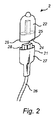
FIG. 2 shows a
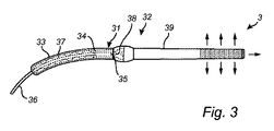
図3は、他の実施例による照明装置32及びコネクタプラグ31を有する照明システム3を示している。本例において、コネクタプラグ31のヒートシンクは、任意には可撓性のカバー33によって覆われている、可撓性の金属ホイル37を有し得る。ホイル37(及びカバー33)は、ひだをつけられ(又は湾曲され)ケーブル36の一部に沿って延在することができる。本例において、コネクタプラグ31は、USB電子接点35を持つUSBコネクタプラグであり、照明装置32は、対応するUSBコネクタ・ポート34を有することができる。コネクタプラグ31と照明装置32との間の熱インターフェースは、例えば、USBプラグ/ポート・インタフェースに設けられることが可能である。更に、本例において、照明装置32は、(例えば型L2の)LED38と、LED38に光学的に結合されている光ガイド39とを有する。光ガイド39は、光ガイド39内で伝播する光を発する光導出結合表面を有することができる。本例において、照明装置31により生成される熱は、前記プラグ/ポート・インタフェースを介して伝導され、次いでコネクタプラグ31の金属ホイル37及びカバー33を介して放散される。
FIG. 3 shows a lighting system 3 having a
図4は、実施例によるコネクタプラグ41に接続された複数の照明装置42を有する照明システム4を示している。照明装置42は、(図4に示されたような)光ガイド、並びに/又はリフレクタ、全内部反射(TIR)コリメータ及び/若しくはレンズ(図示略)のような他の光学要素を有することができる。本例において、コネクタプラグ41は、好ましくは金属でできている、ヒートシンク・ブロック47を有することができる。ブロック47は、コネクタプラグ41の熱放散領域を増大させるための1つ以上のフィン48を有することができる。コネクタプラグ41は、内部にコネクタプラグ41の電子接点が配されることができる1つ以上のポート44を有することができる。照明装置42は、ポート44内への挿入のためのプラグ43を含むことができる。照明装置42の電子接点は、プラグ43内に配されることができる。本例において、照明装置42により生成される熱は、コネクタプラグ41の後ろ47を経て放散される。
FIG. 4 shows a lighting system 4 having a plurality of
図5は、他の実施例による照明装置52及びコネクタプラグ51を有する照明システム5を示している。本例において、コネクタプラグ51は、スナップフィット固定配置53を持つカテゴリ5(CAT―5)接点を有し、照明装置52は、嵌合スナップフィット固定配置を備える対応するCAT―5コネクタ・ポート56を有する。照明装置52は、更に、照明装置52の突起部分55を形成すると共に熱放散インターフェース59を持っているヒートシンクを有する。コネクタプラグ51は、照明装置52がコネクタプラグ51に結合される場合に、照明装置52の熱放散インターフェース59がコネクタプラグ51の熱受容インターフェース54と重なる及びコネクタプラグ51の熱受容インターフェース54に直接的に接触するように配されている熱受容面54を持つヒートシンク57を有する。本例において、コネクタプラグ51のヒートシンク57は1つ以上のフィン(又はウィング)58を有することができ、1つ以上のフィン(又はウィング)58の表面はコネクタプラグ51の熱放散インターフェース(の少なくとも一部)を形成する。任意には、フィン58はひだをつけられることもできる。コネクタプラグ51が照明装置52に結合される場合、熱放散インターフェース59はコネクタプラグ51の熱受容インターフェース54にわたる適所において摺動し、これにより熱は照明装置52からコネクタプラグ51まで伝導され、この後にフィン58を介して放散されるようにされることができる。
FIG. 5 shows a
図6は、実施例によるコネクタプラグ61の斜視図である。図7は、図6に示されるコネクタプラグ61の断面図を示している。本例において、コネクタプラグ61は、CAT―5又はCAT―6コネクタプラグのような、CAT―x型の接点であり、CAT―x電子接点65を有する。電子接点65は、ヒートシンク層67及び外側カバー層68を有するスリーブ64によって少なくとも部分的に包囲されている。スリーブ64の端部に、スナップフィット固定配置63が配される。照明装置がコネクタプラグ61に接続されている場合、前記照明装置の対応するCAT―xコネクタ・ポートは、コネクタプラグ61の電子接点65が照明装置(図示略)のコネクタ・ポートの前記電子接点と接触するようになるように、スリーブ64内に挿入される。前記照明装置の前記コネクタ・ポートの外側は、次いで、スリーブ64のヒートシンク層67の内面と接触するようになることができ、これにより熱は、前記照明装置からコネクタプラグ61のヒートシンク層67まで伝導されることができる。前記熱は、次いで、ヒートシンク67からカバー68を介して周囲に放散されることができる。
FIG. 6 is a perspective view of the
図8は、照明装置62に接続されている図6及び7を参照して記載されているコネクタプラグ61を示している。コネクタプラグ61のケーブル66は、照明装置62を懸架するために使用されることができる。任意には、コネクタプラグ61は、照明装置62により発される光を反射するように配されたリフレクタ64を有する。
FIG. 8 shows the
本発明の実施例が示され添付図面及び上述において、詳細に記載されたが、このような図例及び説明は、説明的なもの又は例示的なものとみなされるべきであり、限定的なものとみなされるべきではなく、本発明は、開示された実施例に限定されるものではない。例えば、前記固定配置は、差し込みピン型又は何らかの他の(好ましくは固い)固定配置の型であっても良い。更に、前記照明装置は、何らかの種類の固体照明装置又は放電ランプのような、如何なる種類の照明装置であっても良い。 While embodiments of the present invention have been shown and described in detail in the accompanying drawings and above, such illustration and description should be considered illustrative or exemplary and limited. The invention is not to be considered as limited to the disclosed embodiments. For example, the fixed arrangement may be a bayonet pin type or some other (preferably hard) fixed arrangement type. Further, the lighting device may be any type of lighting device, such as some kind of solid state lighting device or a discharge lamp.
開示された実施例に対する他の変更は、添付の図面、本明細書及び添付の特許請求の範囲の研究から、前記請求項に記載の発明を実施する際に当業者により理解され遂行されることができる。添付の請求項において、「有する」なる語は他の要素又はステップを排除するものではなく、単数形は複数形を排除するものではない。特定の手段が、相互に異なる従属請求項において、引用されているという単なる事実は、これらの手段の組み合わせが有利になるように使用されることができないと示すものではない。添付請求項における如何なる符号も、この範囲を制限するものとしてみなしてはならない。 Other modifications to the disclosed embodiments will be understood and carried out by those skilled in the art in practicing the claimed invention, from a study of the accompanying drawings, the specification and the appended claims. Can do. In the appended claims, the word “comprising” does not exclude other elements or steps, and the singular does not exclude the plural. The mere fact that certain measures are recited in mutually different dependent claims does not indicate that a combination of these measures cannot be used to advantage. Any reference signs in the claims should not be construed as limiting the scope.
Claims (12)
前記照明装置を機械的に前記コネクタプラグに結合するための固定配置と、
前記コネクタプラグに結合された前記照明装置に電力を輸送する及び前記コネクタプラグに結合された前記照明装置とデータを通信するための電子接点であって、前記電子接点は、ユニバーサル・シリアル・バス(USB)型の接点又はモジュラー・コネクタ型の接点であり、ケーブルに電気的に接続されるように配されている、電子接点と、
前記コネクタプラグに結合されている前記照明装置から熱を受け取る熱受容インターフェースと、前記熱受容インターフェースを介して受け取られた前記熱の少なくとも一部を放散させる熱放散インターフェースを有するヒートシンクと、
を有するコネクタプラグ。 A connector plug for a lighting device,
A fixed arrangement for mechanically coupling the lighting device to the connector plug;
Electronic contacts for transporting power to the lighting device coupled to the connector plug and for communicating data with the lighting device coupled to the connector plug, the electronic contact comprising a universal serial bus ( USB) type contact or modular connector type contact, electronic contact arranged to be electrically connected to the cable;
A heat receiving interface for receiving heat from the lighting device coupled to the connector plug; and a heat sink having a heat dissipating interface for dissipating at least a portion of the heat received through the heat receiving interface;
Having a connector plug.
前記コネクタプラグに前記照明装置を機械的に結合させるための固定配置と、
前記コネクタプラグから電力を受け取る及び前記コネクタプラグとデータを通信するための電子接点であって、前記電子接点は、ユニバーサル・シリアル・バス(USB)型の接点又はモジュラー・コネクタ型の接点である、電子接点と、
前記照明装置により生成される熱を前記コネクタプラグに輸送する熱放散インターフェースと、
を有するコネクタ・ポート配置を有する前記照明装置。 A lighting device coupled to the connector plug according to any one of claims 1 to 8 ,
A fixed arrangement for mechanically coupling the lighting device to the connector plug;
An electronic contact for receiving power from the connector plug and communicating data with the connector plug , wherein the electronic contact is a universal serial bus (USB) type contact or a modular connector type contact; Electronic contacts;
A heat dissipation interface for transporting heat generated by the lighting device to the connector plug;
The illuminating device having a connector port arrangement.
Applications Claiming Priority (3)
| Application Number | Priority Date | Filing Date | Title |
|---|---|---|---|
| EP13187424 | 2013-10-04 | ||
| EP13187424.0 | 2013-10-04 | ||
| PCT/EP2014/070995 WO2015049258A1 (en) | 2013-10-04 | 2014-10-01 | Lighting device connector comprising a heat sink |
Publications (3)
| Publication Number | Publication Date |
|---|---|
| JP2016532252A JP2016532252A (en) | 2016-10-13 |
| JP2016532252A5 JP2016532252A5 (en) | 2017-11-09 |
| JP6369876B2 true JP6369876B2 (en) | 2018-08-08 |
Family
ID=49328367
Family Applications (1)
| Application Number | Title | Priority Date | Filing Date |
|---|---|---|---|
| JP2016520005A Active JP6369876B2 (en) | 2013-10-04 | 2014-10-01 | Lighting device connector having a heat sink |
Country Status (5)
| Country | Link |
|---|---|
| US (1) | US10033141B2 (en) |
| EP (1) | EP3053225B1 (en) |
| JP (1) | JP6369876B2 (en) |
| CN (1) | CN105594074B (en) |
| WO (1) | WO2015049258A1 (en) |
Families Citing this family (9)
| Publication number | Priority date | Publication date | Assignee | Title |
|---|---|---|---|---|
| US9893474B1 (en) | 2016-10-12 | 2018-02-13 | International Business Machines Corporation | Active cable heat sink |
| GB2559961B (en) * | 2017-02-16 | 2019-07-17 | Aurora Ltd | Improved downlight with a detachable electronic module |
| US10215377B2 (en) * | 2017-02-20 | 2019-02-26 | Klik Systems Ltd Pty | Light assembly and a method of securing the light assembly into an opening in a thin wall |
| JP2018148811A (en) * | 2017-03-10 | 2018-09-27 | オリンパス株式会社 | Observation device and communication cable |
| DE102017204939A1 (en) * | 2017-03-23 | 2018-09-27 | Te Connectivity Germany Gmbh | An electrical connector and electrical connection assembly comprising an electrical connector |
| JP6956680B2 (en) * | 2018-05-16 | 2021-11-02 | 富士フイルム株式会社 | Manufacturing method of mold case and microneedle array |
| US10852497B2 (en) * | 2019-02-27 | 2020-12-01 | Ciena Corporation | Pluggable optical module thermal management and heat shield assemblies, devices, and methods |
| US11515676B2 (en) | 2020-02-21 | 2022-11-29 | Qualcomm Incorporated | Thermal mitigation for USB power delivery |
| CN211625115U (en) * | 2020-03-09 | 2020-10-02 | 上犹县嘉亿灯饰制品有限公司 | Point control copper wire lamp and lamp |
Family Cites Families (47)
| Publication number | Priority date | Publication date | Assignee | Title |
|---|---|---|---|---|
| US3237341A (en) * | 1962-12-19 | 1966-03-01 | Roger S Dybvig | Base and stackable elements having cooperating electrical contact means |
| US4573754A (en) * | 1984-03-14 | 1986-03-04 | U.S. Plastics Corp. | Lamp assembly |
| US4780799A (en) | 1986-10-23 | 1988-10-25 | Lighting Technology, Inc. | Heat-dissipating light fixture for use with tungsten-halogen lamps |
| US4804343A (en) * | 1988-04-11 | 1989-02-14 | General Motors Corporation | Lamp socket assembly |
| US5435741A (en) * | 1994-04-12 | 1995-07-25 | Wang; Jen-Sheng | Bulb fastening structure for christmas light strings |
| JPH08250248A (en) * | 1995-01-14 | 1996-09-27 | Koito Mfg Co Ltd | Bulb socket |
| EP0806817A1 (en) * | 1996-05-09 | 1997-11-12 | REGGIANI S.p.A. ILLUMINAZIONE | Universal lamp-holder |
| US5685638A (en) * | 1996-06-07 | 1997-11-11 | Huang; Chin-Wang | Waterproof structure for a decorative light |
| US6232707B1 (en) * | 1998-11-16 | 2001-05-15 | General Electric Company | Wedge base lamp |
| US6409547B1 (en) * | 1998-12-02 | 2002-06-25 | Nordx/Cdt, Inc. | Modular connectors with compensation structures |
| US6467942B2 (en) * | 2001-01-12 | 2002-10-22 | Alcoa Fujikura Limited | Automotive lamp socket |
| US6626703B2 (en) * | 2002-02-05 | 2003-09-30 | Liao Sheng Hsin | Multipurpose adaptor with a universal serial bus connector |
| US6752663B2 (en) | 2002-03-06 | 2004-06-22 | Tyco Electronics Corporation | Receptacle assembly having shielded receptacle connector interface with pluggable electronic module |
| TW584372U (en) | 2002-03-13 | 2004-04-11 | Cyber Internat Co Ltd A | Heat dissipation apparatus with serial and parallel connection ports |
| US6787990B2 (en) | 2002-05-28 | 2004-09-07 | Eastman Kodak Company | OLED area illumination light source having flexible substrate on a support |
| US20060072302A1 (en) | 2004-10-01 | 2006-04-06 | Chien Tseng L | Electro-luminescent (EL) illuminated wall plate device with push-tighten frame means |
| US7052301B2 (en) * | 2003-06-17 | 2006-05-30 | Christiana Industries, Inc. | Lamp socket |
| US20060133064A1 (en) * | 2004-12-20 | 2006-06-22 | Ming-Kuei Lin | Mini dynamic light |
| US20090011793A1 (en) * | 2005-01-13 | 2009-01-08 | Pocrass Alan L | Flash Memory Cell Phone With Integrated Male And Female Connectors |
| US20060258215A1 (en) | 2005-05-12 | 2006-11-16 | Chang-Chin Lai | USB aromatic dispenser |
| HK1077973A2 (en) | 2005-11-28 | 2006-02-24 | Zheng Bo | A thermostat with usb hub function |
| US8636385B2 (en) * | 2006-12-15 | 2014-01-28 | Koninklijke Philips N.V. | Sensor module connector |
| US7479044B1 (en) * | 2007-12-07 | 2009-01-20 | St. Clair Technologies, Inc. | Lamp socket |
| CN101685762B (en) * | 2008-08-01 | 2011-12-14 | 科技专利许可公司 | Method for securing a minature blub in a holder |
| US7800909B2 (en) * | 2008-10-27 | 2010-09-21 | Edison Opto Corporation | Lamp base having a heat sink |
| US20100309657A1 (en) * | 2009-06-04 | 2010-12-09 | Beverly Purdy | USB memory device with integrated flashlight |
| US8172427B2 (en) * | 2009-11-25 | 2012-05-08 | Fu-Hsien Hsu | LED decorative lamp |
| TWI381268B (en) | 2009-12-04 | 2013-01-01 | Wistron Neweb Corp | Usb device |
| MX2012012462A (en) * | 2010-04-26 | 2012-11-30 | Xicato Inc | Led-based illumination module attachment to a light fixture. |
| US8237381B2 (en) * | 2010-05-04 | 2012-08-07 | Xicato, Inc. | Flexible electrical connection of an LED-based illumination device to a light fixture |
| US8541945B2 (en) | 2010-06-04 | 2013-09-24 | Schwarz Reliance Llc | Lighting device |
| CN201718153U (en) | 2010-06-11 | 2011-01-19 | 华为终端有限公司 | Rotary data card |
| GB201014056D0 (en) * | 2010-08-23 | 2010-10-06 | Litonics Ltd | Heatsink for lighting device |
| US8568015B2 (en) * | 2010-09-23 | 2013-10-29 | Willis Electric Co., Ltd. | Decorative light string for artificial lighted tree |
| CN201909192U (en) | 2010-09-26 | 2011-07-27 | 邓建伟 | Improved LED (light-emitting diode) module |
| TWM412312U (en) * | 2011-01-31 | 2011-09-21 | Ceramate Technical Co Ltd | Multi-functional magnetic attraction type LED lamp which is easy to attach/detach |
| US8998458B2 (en) * | 2011-05-31 | 2015-04-07 | Sabic Global Technologies B.V. | LED plastic heat sink and method for making and using the same |
| JP5785788B2 (en) | 2011-06-10 | 2015-09-30 | 株式会社アイ・オー・データ機器 | Universal serial bus device |
| TWI479983B (en) * | 2011-06-23 | 2015-04-01 | Mstar Semiconductor Inc | Monolithical fin-type heat sink |
| TWM421457U (en) * | 2011-07-06 | 2012-01-21 | Ceramate Technical Co Ltd | Non-disposable LED lamp with laminated heat dissipation |
| US20130043781A1 (en) * | 2011-08-15 | 2013-02-21 | Robert Wang | Integral lamp with a replaceable light source |
| US8419225B2 (en) | 2011-09-19 | 2013-04-16 | Osram Sylvania Inc. | Modular light emitting diode (LED) lamp |
| US20130157499A1 (en) | 2011-12-20 | 2013-06-20 | International Business Machines Corporation | Active electrical connection with self-engaging, self-releasing heat-sink |
| US8985815B2 (en) * | 2012-09-14 | 2015-03-24 | Chicony Power Technology Co., Ltd. | Light bulb with upward and downward facing LEDs having heat dissipation |
| CN202884549U (en) * | 2012-09-24 | 2013-04-17 | 李祎明 | Light-emitting diode (LED) bulb with universal serial bus (USB) interface |
| US9157624B2 (en) * | 2013-03-14 | 2015-10-13 | Bby Solutions, Inc. | Modular LED bulb with user replaceable components |
| TWI487867B (en) * | 2013-03-20 | 2015-06-11 | 隆達電子股份有限公司 | Dual-use lighting bulb having ac and dc leds |
-
2014
- 2014-10-01 CN CN201480054837.2A patent/CN105594074B/en active Active
- 2014-10-01 WO PCT/EP2014/070995 patent/WO2015049258A1/en active Application Filing
- 2014-10-01 JP JP2016520005A patent/JP6369876B2/en active Active
- 2014-10-01 EP EP14781136.8A patent/EP3053225B1/en active Active
- 2014-10-01 US US15/027,159 patent/US10033141B2/en active Active
Also Published As
| Publication number | Publication date |
|---|---|
| EP3053225B1 (en) | 2020-05-06 |
| WO2015049258A1 (en) | 2015-04-09 |
| CN105594074A (en) | 2016-05-18 |
| EP3053225A1 (en) | 2016-08-10 |
| US20160254623A1 (en) | 2016-09-01 |
| US10033141B2 (en) | 2018-07-24 |
| JP2016532252A (en) | 2016-10-13 |
| CN105594074B (en) | 2019-05-31 |
Similar Documents
| Publication | Publication Date | Title |
|---|---|---|
| JP6369876B2 (en) | Lighting device connector having a heat sink | |
| EP2257730B1 (en) | Integrated led driver for led socket | |
| US8696168B2 (en) | Illumination device | |
| JP4908616B2 (en) | Connector and lighting device | |
| US9638409B2 (en) | LED lamp | |
| US20130020941A1 (en) | Semiconductor Lamp | |
| JP5799850B2 (en) | Lamp apparatus and lighting apparatus | |
| US9464802B2 (en) | Flow controlled effective LED based lighting system | |
| KR101449821B1 (en) | Heat dissipation device and lighting device | |
| US20140204572A1 (en) | System for Adapting an Existing Florescent Light Fixture with an LED Luminaire | |
| CN103968279A (en) | Lamp Device, Light-Emitting Device and Luminaire | |
| US9951910B2 (en) | LED lamp with base having a biased electrical interconnect | |
| US9052068B2 (en) | Dual-use light fixture having AC and DC LEDs | |
| KR20080058878A (en) | Light emitting diode lighting apparatus | |
| JP2011181252A (en) | Lighting fixture | |
| US10871281B2 (en) | Lighting device with light guide | |
| WO2015197387A1 (en) | Led light source | |
| TWI573957B (en) | Heat sink apparatus for solid state lights | |
| JP7017400B2 (en) | Lighting equipment | |
| AU2013100478A4 (en) | Retrofit LED lighting system | |
| KR101651476B1 (en) | Lighting device | |
| KR20150008980A (en) | Lighting apparatus | |
| KR20110091326A (en) | Polyhedron led light bulb | |
| AU2013204414A1 (en) | Retrofit LED lighting system | |
| KR20140002961U (en) | LED lamp |
Legal Events
| Date | Code | Title | Description |
|---|---|---|---|
| A521 | Request for written amendment filed |
Free format text: JAPANESE INTERMEDIATE CODE: A523 Effective date: 20170927 |
|
| A621 | Written request for application examination |
Free format text: JAPANESE INTERMEDIATE CODE: A621 Effective date: 20170927 |
|
| A977 | Report on retrieval |
Free format text: JAPANESE INTERMEDIATE CODE: A971007 Effective date: 20180525 |
|
| TRDD | Decision of grant or rejection written | ||
| A01 | Written decision to grant a patent or to grant a registration (utility model) |
Free format text: JAPANESE INTERMEDIATE CODE: A01 Effective date: 20180606 |
|
| A61 | First payment of annual fees (during grant procedure) |
Free format text: JAPANESE INTERMEDIATE CODE: A61 Effective date: 20180704 |
|
| R150 | Certificate of patent or registration of utility model |
Ref document number: 6369876 Country of ref document: JP Free format text: JAPANESE INTERMEDIATE CODE: R150 |
|
| S531 | Written request for registration of change of domicile |
Free format text: JAPANESE INTERMEDIATE CODE: R313531 |
|
| S533 | Written request for registration of change of name |
Free format text: JAPANESE INTERMEDIATE CODE: R313533 |
|
| R350 | Written notification of registration of transfer |
Free format text: JAPANESE INTERMEDIATE CODE: R350 |
|
| R250 | Receipt of annual fees |
Free format text: JAPANESE INTERMEDIATE CODE: R250 |
|
| R250 | Receipt of annual fees |
Free format text: JAPANESE INTERMEDIATE CODE: R250 |