JP6368070B2 - Game machine - Google Patents
Game machine Download PDFInfo
- Publication number
- JP6368070B2 JP6368070B2 JP2013048538A JP2013048538A JP6368070B2 JP 6368070 B2 JP6368070 B2 JP 6368070B2 JP 2013048538 A JP2013048538 A JP 2013048538A JP 2013048538 A JP2013048538 A JP 2013048538A JP 6368070 B2 JP6368070 B2 JP 6368070B2
- Authority
- JP
- Japan
- Prior art keywords
- variable display
- big hit
- special symbol
- display
- state
- Prior art date
- Legal status (The legal status is an assumption and is not a legal conclusion. Google has not performed a legal analysis and makes no representation as to the accuracy of the status listed.)
- Active
Links
Images


Description
本発明は、遊技領域に設けられた特別始動領域を遊技媒体が通過したことにもとづいて特別識別情報を可変表示して表示結果を導出表示する特別可変表示手段に予め定められた特定表示結果が導出表示されたときに、遊技者にとって有利な特定遊技状態に制御する遊技機に関する。 The present invention provides a special display result predetermined for special variable display means for variably displaying special identification information and deriving and displaying a display result based on the fact that the game medium has passed through a special start area provided in the game area. The present invention relates to a gaming machine that controls to a specific gaming state that is advantageous for a player when it is derived and displayed.
従来の遊技機としては、大当り遊技終了後の遊技状態を、遊技者が打ち込んだ遊技球数に対する賞球数の比率を示す出玉率(ベース)が高い状態(高ベース状態)であり、且つ大当り遊技状態に制御される確率が通常よりも高い特別遊技状態(高確高ベース状態)に制御しているものがある。このような遊技機では、普通図柄の当り確率を高めることにより始動入賞口の開放頻度を向上させることで、該始動入賞口への遊技球の始動入賞に伴う賞球の払出により高ベース状態を実現している(例えば、特許文献1参照)。 As a conventional gaming machine, the game state after the big hit game is in a state (high base state) in which the ratio of the number of winning balls (base) indicating the ratio of the number of prize balls to the number of game balls that the player has struck is high (high base state) Some of them are controlled to a special gaming state (highly accurate high base state) in which the probability of being controlled to the big hit gaming state is higher than usual. In such a gaming machine, by increasing the opening frequency of the start winning opening by increasing the probability of hitting a normal symbol, a high base state is achieved by paying out the winning ball accompanying the starting winning of the game ball to the starting winning opening. (For example, refer patent document 1).
しかしながら、特許文献1にあっては、高ベース状態において特別図柄の変動表示結果がハズレとなる場合は、特別図柄の変動表示結果が大当りとなる場合に比べて変動表示時間が短い特別図柄の変動パターンが実行される場合があるため、これらハズレとなる場合に変動表示時間が短い特別図柄の変動が実施されてしまうと、1の特別図柄の変動中において普通図柄の当りとなる回数が少なくなってしまうので、興趣が低下してしまうという問題がある。
However, in
本発明は、このような問題点に着目してなされたもので、特別遊技状態において、特別図柄の変動表示結果がハズレとなる場合でもあっても興趣の低下を防ぐことができる遊技機を提供することを目的とする。 The present invention has been made paying attention to such problems, and provides a gaming machine capable of preventing a decrease in interest even in a special gaming state even when a special symbol variation display result is lost. The purpose is to do.
前記課題を解決するために、本発明の請求項1に記載の遊技機は、
特別始動領域(例えば、普通可変入賞球装置20にて構成される始動入賞口)を遊技媒体(例えば、遊技球)が通過したことにもとづく第1識別情報(特別図柄)の可変表示の表示結果として特定表示結果(例えば、大当り図柄)が導出されたときに、遊技者にとって有利な特定状態(例えば、大当り遊技状態)に制御する遊技機(パチンコ遊技機1)であって、
前記第1識別情報の可変表示の表示結果を前記特定表示結果とするか否かを決定する決定手段(例えば、CPU56が大当り判定処理を実行する部分)と、
前記第1識別情報の可変表示を開始するとき(例えば、CPU56が特別図柄変動開始処理を実行するとき)に、該可変表示の可変表示期間を決定する可変表示期間決定手段(例えば、CPU56が特別図柄変動パターン設定処理を実行する部分)と、
前記特別始動領域を遊技媒体が通過したことを含む付与条件(例えば、大入賞口スイッチ14aがオンとなった場合、始動口スイッチ23がオンとなった場合、入賞口スイッチ33aがオンとなった場合)の成立にもとづいて遊技価値(例えば、賞球)を付与する遊技価値付与手段(例えば、CPU56が賞球処理を実行する部分)と、
普通始動領域(例えば、ゲート32A,32B)を遊技媒体が通過したことにもとづく第2識別情報(普通図柄)の可変表示として所定表示結果(例えば、当り図柄)が導出されたときに前記特別始動領域を遊技媒体が通過しにくい又はしない第1状態(例えば、閉鎖状態)から遊技媒体が通過し易い第2状態(例えば、開放状態)に変化する可変入賞装置(例えば、可変入賞球装置20)と、
1の前記特定状態が終了したときから終了条件が成立するまでの単位期間において、遊技に使用される使用遊技価値(例えば、遊技者が打ち込んだ遊技球数)と前記遊技価値付与手段にて付与される付与遊技価値(例えば、賞球数)との比率が通常状態(例えば、低ベース状態)における通常比率(例えば、1より小さい値である0.2〜0.4)よりも大きい特別比率(例えば、1よりも大きい値である1.1〜1.4)となるように、前記可変入賞装置が前記第2状態に変化する頻度を向上させる特別状態(例えば、高ベース状態)に制御する状態制御手段(例えば、CPU56が大当り終了処理のステップS478、ステップS475、ステップS474b、ステップS477において第1高ベースフラグまたは第2高ベースフラグをセットする部分)と、
を備え、
前記終了条件は、前記単位期間の開始となる前記特定状態の終了後において新たな前記特定状態に制御される(例えば、高ベースフラグがセットされている状態において、CPU56が特別図柄停止処理のステップS233で大当りフラグがセットされている場合、ステップS234にて高ベースフラグをリセットした後にステップS303〜ステップ307を実行する部分)ことを少なくとも1の条件として含み、
前記可変表示期間決定手段は、前記特別状態における前記第1識別情報の可変表示期間を、第1可変表示期間(例えば、10秒)と該第1可変表示期間よりも長い第2可変表示期間(例えば、150秒)と該第2可変表示期間より長い第3可変表示期間(例えば、300秒)とを含む複数の可変表示期間から決定可能であって(例えば、特別図柄変動パターン設定処理においてCPU56がステップS284、ステップS287b、ステップS287c、ステップS288、ステップS291、ステップS294b、ステップS294c、ステップS295のいずれかを実行後、ステップS296aを実行する部分)、
前記可変表示期間決定手段は、前記決定手段が前記特定表示結果とすると決定しないとき(特別図柄の変動表示結果がハズレであるとき)には前記特定表示結果とすると決定するとき(特別図柄の変動表示結果が大当りであるとき)に比較して高い割合にて前記第2可変表示期間及び前記第3可変表示期間のうちのいずれかを決定し(例えば、CPU56は、特別図柄の変動表示結果がハズレであるときは、特別図柄の変動表示結果が大当りであるときに選択される変動パターン決定テーブル(図24)よりも変動表示時間が150秒と300秒の変動パターンに決定値が多く設定されている変動パターン決定テーブル(図25)を選択して、ステップS296aにて変動パターンを決定する)、
前記可変表示期間決定手段による決定前に、前記第2可変表示期間及び前記第3可変表示期間のうちのいずれかが決定されるか否かを判定する判定手段と、
前記判定手段の判定結果に基づいて、前記特別状態において、前記第2可変表示期間及び前記第3可変表示期間のうちのいずれかの可変表示が実行される可能性を示唆する示唆演出を、該第2可変表示期間及び前記第3可変表示期間のうちのいずれかの可変表示が開始される前に実行可能な示唆演出実行手段と、
をさらに備え、
前記示唆演出実行手段は、前記示唆演出として、第1示唆演出と第2示唆演出とを実行可能であって、前記判定手段によって前記第3可変表示期間が決定されると判定されたときには、前記判定手段によって前記第2可変表示期間が決定されると判定されたときよりも高い割合にて前記第2示唆演出を実行可能である
ことを特徴としている。
この特徴によれば、特別状態において可変表示の表示結果として特定表示結果が導出表示されないときには特定表示結果が導出表示されるときよりも第2可変表示期間及び前記第3可変表示期間のうちのいずれかが決定され易くなるので、特定表示結果が導出表示されないときの遊技の興趣低下を防ぐことができる。
In order to solve the above-mentioned problem, a gaming machine according to
Display result of variable display of first identification information (special symbol) based on passage of game medium (for example, game ball) through special start area (for example, start prize opening configured by normal variable winning ball device 20) When a specific display result (for example, jackpot symbol) is derived as a gaming machine (pachinko gaming machine 1) that controls to a specific state (for example, jackpot gaming state) advantageous to the player,
Determining means for determining whether or not the display result of the variable display of the first identification information is the specific display result (for example, a portion where the
When the variable display of the first identification information is started (for example, when the
Grant conditions including passing of the game medium through the special starting area (for example, when the big winning
The special start when a predetermined display result (for example, winning symbol) is derived as a variable display of the second identification information (ordinary symbol) based on the fact that the game medium has passed through the normal starting region (for example, the
1 used game value (for example, the number of game balls that a player has struck) and given by the game value giving means during a unit period from when the specific state is finished until the end condition is satisfied Special ratio in which the ratio to the assigned game value (for example, the number of prize balls) is larger than the normal ratio (for example, 0.2 to 0.4 which is a value smaller than 1) in the normal state (for example, low base state) (For example, 1.1 to 1.4 which is a value larger than 1) Control to a special state (for example, a high base state) that improves the frequency with which the variable winning device changes to the second state. State control means (for example, the
With
The end condition is controlled to the new specific state after the end of the specific state at the start of the unit period (for example, in a state where the high base flag is set, the
The variable display period determining means sets a variable display period of the first identification information in the special state as a first variable display period (for example, 10 seconds) and a second variable display period longer than the first variable display period ( For example, it can be determined from a plurality of variable display periods including a third variable display period (for example, 300 seconds) longer than the second variable display period (for example, the
The variable display period determining means determines that the specific display result is determined when the determining means does not determine the specific display result (when the variation display result of the special symbol is lost). One of the second variable display period and the third variable display period is determined at a higher rate than when the display result is a big hit (for example, the
Determination means for determining whether one of the second variable display period and the third variable display period is determined before the determination by the variable display period determination means;
Based on the determination result of the determination means, in the special state, a suggestion effect that suggests the possibility of executing variable display of either the second variable display period or the third variable display period , Suggestive effect execution means that can be executed before the start of variable display in any of the second variable display period and the third variable display period ;
Further comprising
The suggestion effect executing means can execute a first suggestion effect and a second suggestion effect as the suggestion effect, and when the determination unit determines that the third variable display period is determined, it is characterized in that Ru executable der the second suggested effect at a higher rate than when the second variable display period is judged to be determined by the determining means.
According to this feature, when the specific display result is not derived and displayed as the display result of the variable display in the special state, any of the second variable display period and the third variable display period is longer than when the specific display result is derived and displayed. Since it is easy to be determined, it is possible to prevent the interest of the game from being reduced when the specific display result is not derived and displayed.
本発明の請求項2に記載の遊技機は、
特別始動領域(例えば、普通可変入賞球装置20にて構成される始動入賞口)を遊技媒体(例えば、遊技球)が通過したことにもとづく第1識別情報(特別図柄)の可変表示の表示結果として特定表示結果(例えば、大当り図柄)が導出されたときに、遊技者にとって有利な特定状態(例えば、大当り遊技状態)に制御する遊技機(パチンコ遊技機1)であって、
前記第1識別情報の可変表示の表示結果を前記特定表示結果とするか否かを決定する決定手段(例えば、CPU56が大当り判定処理を実行する部分)と、
前記第1識別情報の可変表示を開始するとき(例えば、CPU56が特別図柄変動開始処理を実行するとき)に、該可変表示の可変表示期間を決定する可変表示期間決定手段(例えば、CPU56が特別図柄変動パターン設定処理を実行する部分)と、
前記特別始動領域を遊技媒体が通過したことを含む付与条件(例えば、大入賞口スイッチ14aがオンとなった場合、始動口スイッチ23がオンとなった場合、入賞口スイッチ33aがオンとなった場合)の成立にもとづいて遊技価値(例えば、賞球)を付与する遊技価値付与手段(例えば、CPU56が賞球処理を実行する部分)と、
普通始動領域(例えば、ゲート32A,32B)を遊技媒体が通過したことにもとづく第2識別情報(普通図柄)の可変表示として所定表示結果(例えば、当り図柄)が導出されたときに前記特別始動領域を遊技媒体が通過しにくい又はしない第1状態(例えば、閉鎖状態)から遊技媒体が通過し易い第2状態例えば、開放状態)に変化する可変入賞装置(例えば、可変入賞球装置20)と、
1の前記特定状態が終了したときから終了条件が成立するまでの単位期間において、遊技に使用される使用遊技価値(例えば、遊技者が打ち込んだ遊技球数)と前記遊技価値付与手段にて付与される付与遊技価値(例えば、賞球数)との比率が通常状態(例えば、低ベース状態)における通常比率(例えば、1より小さい値である0.2〜0.4)よりも大きい特別比率(例えば、1よりも大きい値である1.1〜1.4)となるように、前記可変入賞装置が前記第2状態に変化する頻度を向上させる特別状態(例えば、高ベース状態)に制御する状態制御手段(例えば、CPU56が大当り終了処理のステップS478、ステップS475、ステップS474b、ステップS477において第1高ベースフラグまたは第2高ベースフラグをセットする部分)と、
を備え、
前記終了条件は、前記単位期間の開始となる前記特定状態の終了後において新たな前記特定状態に制御される(例えば、高ベースフラグがセットされている状態において、CPU56が特別図柄停止処理のステップS233で大当りフラグがセットされている場合、ステップS234にて高ベースフラグをリセットした後にステップS303〜ステップ307を実行する部分)ことを少なくとも1の条件として含み、
前記可変表示期間決定手段は、前記特別状態における前記第1識別情報の可変表示期間を、第1可変表示期間(例えば、10秒)と該第1可変表示期間よりも長い第2可変表示期間(例えば、150秒)と該第2可変表示期間より長い第3可変表示期間(例えば、300秒)とを含む複数の可変表示期間から決定可能であって(例えば、特別図柄変動パターン設定処理においてCPU56がステップS284、ステップS287b、ステップS287c、ステップS288、ステップS291、ステップS294b、ステップS294c、ステップS295のいずれかを実行後、ステップS296aを実行する部分)、
前記可変表示期間決定手段は、前記決定手段が前記特定表示結果とすると決定するとき(特別図柄の変動表示結果が大当りであるとき)には前記第2可変表示期間及び前記第3可変表示期間を決定せず(例えば、特別図柄の変動表示結果が大当りである場合は、変動表示時間が10秒である変動パターンにのみ決定値が設定されている変動パターン決定テーブル(図50)を選択して、ステップS296aにおいて変動パターンを決定する)、前記決定手段が前記特定表示結果とすると決定しないとき(特別図柄の変動表示結果がハズレであるとき)には前記第2可変表示期間及び前記第3可変表示期間のうちのいずれかを決定可能であり(例えば、特別図柄の変動表示結果がハズレである場合は、変動表示時間が10秒の変動パターン、150秒の変動パターン、300秒の変動パターンに決定値が設定されている変動パターン決定テーブル(図51)を選択して、ステップS296aにおいて変動パターンを決定する)
前記可変表示期間決定手段による決定前に、前記第2可変表示期間及び前記第3可変表示期間のうちのいずれかが決定されるか否かを判定する判定手段と、
前記判定手段の判定結果に基づいて、前記特別状態において、前記第2可変表示期間及び前記第3可変表示期間のうちのいずれかの可変表示が実行される可能性を示唆する示唆演出を、該第2可変表示期間及び前記第3可変表示期間のうちのいずれかの可変表示が開始される前に実行可能な示唆演出実行手段と、
をさらに備え、
前記示唆演出実行手段は、前記示唆演出として、第1示唆演出と第2示唆演出とを実行可能であって、前記判定手段によって前記第3可変表示期間が決定されると判定されたときには、前記判定手段によって前記第2可変表示期間が決定されると判定されたときよりも高い割合にて前記第2示唆演出を実行可能である
ことを特徴としている。
この特徴によれば、特別状態において可変表示の表示結果として特定表示結果が導出表示されないときには第2可変表示期間及び前記第3可変表示期間のうちのいずれかが決定される場合があるので、特定表示結果が導出表示されないときの遊技の興趣低下を防ぐことができる。
A gaming machine according to
Display result of variable display of first identification information (special symbol) based on passage of game medium (for example, game ball) through special start area (for example, start prize opening configured by normal variable winning ball device 20) When a specific display result (for example, jackpot symbol) is derived as a gaming machine (pachinko gaming machine 1) that controls to a specific state (for example, jackpot gaming state) advantageous to the player,
Determining means for determining whether or not the display result of the variable display of the first identification information is the specific display result (for example, a portion where the
When the variable display of the first identification information is started (for example, when the
Grant conditions including passing of the game medium through the special starting area (for example, when the big winning
The special start when a predetermined display result (for example, winning symbol) is derived as a variable display of the second identification information (ordinary symbol) based on the fact that the game medium has passed through the normal starting region (for example, the
1 used game value (for example, the number of game balls that a player has struck) and given by the game value giving means during a unit period from when the specific state is finished until the end condition is satisfied Special ratio in which the ratio to the assigned game value (for example, the number of prize balls) is larger than the normal ratio (for example, 0.2 to 0.4 which is a value smaller than 1) in the normal state (for example, low base state) (For example, 1.1 to 1.4 which is a value larger than 1) Control to a special state (for example, a high base state) that improves the frequency with which the variable winning device changes to the second state. State control means (for example, the
With
The end condition is controlled to the new specific state after the end of the specific state at the start of the unit period (for example, in a state where the high base flag is set, the
The variable display period determining means sets a variable display period of the first identification information in the special state as a first variable display period (for example, 10 seconds) and a second variable display period longer than the first variable display period ( For example, it can be determined from a plurality of variable display periods including a third variable display period (for example, 300 seconds) longer than the second variable display period (for example, the
The variable display period determining means determines the second variable display period and the third variable display period when the determining means determines that the specific display result is to be used (when the variable symbol display result is a big hit). Not determined (for example, when the variation display result of the special symbol is a big hit, select the variation pattern determination table (FIG. 50) in which the determined value is set only for the variation pattern whose variation display time is 10 seconds. In step S296a, the variation pattern is determined), and when the determining means does not determine that the specific display result is the specific display result (when the special symbol variation display result is lost), the second variable display period and the third variable display period are determined. variation pattern may be determined either (e.g., when the fluctuation display result of the special symbols is losing, the variation display time of 10 seconds in the display period, 1 0 seconds fluctuation pattern, 300 seconds fluctuation pattern of decision values change pattern determination table set by selecting (Fig. 51), to determine the variation pattern in step S296a)
Determination means for determining whether one of the second variable display period and the third variable display period is determined before the determination by the variable display period determination means;
Based on the determination result of the determination means, in the special state, a suggestion effect that suggests the possibility of executing variable display of either the second variable display period or the third variable display period , Suggestive effect execution means that can be executed before the start of variable display in any of the second variable display period and the third variable display period ;
Further comprising a,
The suggestion effect executing means can execute a first suggestion effect and a second suggestion effect as the suggestion effect, and when the determination unit determines that the third variable display period is determined, it is characterized in that Ru executable der the second suggested effect at a higher rate than when the second variable display period is judged to be determined by the determining means.
According to this feature, when the specific display result is not derived and displayed as the display result of the variable display in the special state, either the second variable display period or the third variable display period may be determined. It is possible to prevent a decrease in the interest of the game when the display result is not derived and displayed.
本発明の手段1に記載の遊技機は、請求項1または請求項2に記載の遊技機であって、
前記可変表示期間決定手段により前記第2可変表示期間が決定されたときに、該第2可変表示期間の可変表示における残り可変表示期間を特定可能に報知する残り期間報知手段(例えば、演出制御用CPU101が特別図柄変動中対応処理においてステップS941a〜ステップS941eを実行して演出表示装置の右下部に残り変動時間を表示する部分)を備える
ことを特徴としている。
この特徴によれば、遊技者は、1の可変表示中においてより多くの普通識別情報の可変表示を実施することのできる第2可変表示期間の可変表示が実行されていることを認識できるようになるとともに、残りの可変表示期間を認識できるようになるので、遊技の興趣を向上させることができる。
The gaming machine according to
When the second variable display period is determined by the variable display period determining means, the remaining period notifying means for notifying the remaining variable display period in the variable display of the second variable display period in an identifiable manner (for example, for effect control) The
According to this feature, the player can recognize that variable display of the second variable display period in which more variable display of more normal identification information can be performed during one variable display is being executed. At the same time, since the remaining variable display period can be recognized, the interest of the game can be improved.
本発明の手段2に記載の遊技機は、請求項1、請求項2、手段1、のいずれかに記載の遊技機であって、
前記可変表示期間決定手段により前記第2可変表示期間が決定されるか否かを、該第2可変表示期間の可変表示が開始される前に判定する開始前判定手段(例えば、変形例においてCPU56が図58の特別図柄変動パターン判定処理を実行する部分)と、
前記開始前判定手段の判定結果に基づいて、前記第2可変表示期間の可変表示が実行される可能性を示唆する示唆演出(例えば、保留表示予告演出)を、該第2可変表示期間の可変表示が開始される前に実行する示唆演出実行手段(例えば、演出制御用CPU101が図60に示す保留表示予告演出決定処理を実行する部分)と、
を備える
ことを特徴としている。
この特徴によれば、第2可変表示期間の可変表示が実施される可能性があることを該第2可変表示期間の可変表示が開始される前に事前に認識できるようになるので、遊技の興趣を高めることができる。
The gaming machine according to means 2 of the present invention is the gaming machine according to any one of
Pre-start determining means for determining whether or not the second variable display period is determined by the variable display period determining means before the variable display in the second variable display period is started (for example, the
Based on the determination result of the pre-start determination means, a suggestion effect (for example, a hold display notice effect) that suggests the possibility of performing variable display in the second variable display period is changed in the second variable display period. Suggestion effect execution means (for example, the portion where the
It is characterized by having.
According to this feature, it is possible to recognize in advance that the variable display of the second variable display period may be performed before the variable display of the second variable display period is started. It can enhance interest.
本発明の手段3に記載の遊技機は、請求項1、請求項2、手段1、手段2のいずれかに記載の遊技機であって、
前記遊技状態制御手段は、前記特別遊技状態として、前記特定遊技状態に制御される確率が通常確率である通常確率特別遊技状態(例えば、低確高ベース状態)または前記特定遊技状態に制御される確率が前記通常確率よりも高い高確率特別遊技状態(例えば、高確高ベース状態)のいずれかに制御し(例えば、CPU56が大当り終了処理のステップS478においてステップS478、ステップS475、ステップS474b、ステップS477のいずれかを実行する部分)、
前記可変表示期間決定手段は、前記通常確率特別遊技状態であるときには前記高確率特別遊技状態であるときに比較して高い割合にて前記第2可変表示期間を決定する(例えば、CPU56は、変動パターン設定処理において、高ベースフラグがセットされており且つ確変フラグがセットされていなければ、高ベースフラグがセットされており且つ確変フラグがセットされている場合に選択される変動パターン決定テーブル(図24(D)及び図25(D))よりも変動表示時間が150秒と300秒である変動パターンに多くの決定値が設定されている変動パターン決定テーブル(図24(B)、図24(C)、図25(B)、図25(C))を選択して、ステップS296aにて変動パターンを決定する)
ことを特徴としている。
この特徴によれば、遊技者に、第1通常確率特別遊技状態と第2通常確率特別遊技状態のいずれの遊技状態になるのかについて注目させることができるので、遊技の興趣を高めることができる。
The gaming machine according to means 3 of the present invention is the gaming machine according to any one of
The gaming state control means controls the special gaming state to a normal probability special gaming state (for example, a low probability base state) in which the probability of being controlled to the specific gaming state is a normal probability or the specific gaming state. It is controlled to one of high probability special gaming states (for example, high probability high base state) whose probability is higher than the normal probability (for example, the
The variable display period determining means determines the second variable display period at a higher rate when in the normal probability special gaming state than when in the high probability special gaming state (for example, the
It is characterized by that.
According to this feature, it is possible to make the player pay attention to which of the first normal probability special game state and the second normal probability special game state, so that the interest of the game can be enhanced.
本発明の手段4に記載の遊技機は、手段3に記載の遊技機であって、
前記遊技状態制御手段により前記通常確率特別遊技状態に制御されていることを特定可能に報知する遊技状態報知手段(例えば、演出制御用CPU101が大当り終了対応処理においてステップ960aまたはステップS961aを実行して背景画像を更新する部分)を備える
ことを特徴としている。
この特徴によれば、第2可変表示期間が決定されることに対する遊技者の期待感を高めることができるようになるので、遊技の興趣を向上させることができる。
The gaming machine according to means 4 of the present invention is the gaming machine according to
The gaming state notifying means (for example, the
According to this feature, the player's expectation for the determination of the second variable display period can be increased, so that the interest of the game can be improved.
本発明の手段5に記載の遊技機は、手段3または手段4に記載の遊技機であって、
前記可変表示期間決定手段は、前記通常確率特別遊技状態に制御されているときには前記第2可変表示期間を含む複数の可変表示期間(例えば、特別図柄変動パターン設定処理においてCPU56が、10秒、150秒、300秒の可変表示期間から1の可変表示期間をステップS284、ステップS287b、ステップS287c、ステップS288、ステップS291、ステップS294b、ステップS294c、ステップS295のいずれかを実行後、ステップS296aを実行して決定する部分)、
前記遊技状態制御手段は、前記通常確率特別遊技状態として第1通常確率特別遊技状態(第1低確高ベース状態)と第2通常確率特別遊技状態(第2低確高ベース状態)とに制御し(例えば、CPU56が大当り終了処理において、第1高ベースフラグをセットするステップS475、または第2高ベースフラグをセットするステップS474b、ステップS477、ステップS478のいずれかを実行する部分)、
前記可変表示期間決定手段は、前記第2可変表示期間を、前記第1通常確率特別遊技状態と前記第2通常確率特別遊技状態とで異なる決定割合にて決定する(例えば、遊技状態が第1低確高ベース状態である場合は、遊技状態が第2低確高ベース状態である場合よりも変動表示時間が300秒である変動パターンに決定値が多く設定されている変動パターン決定テーブル(図24(B)、図25(B))に基づいて変動パターンを決定する)
ことを特徴としている。
この特徴によれば、遊技者に、第1通常確率特別遊技状態と第2通常確率特別遊技状態のいずれの遊技状態になるのかについて注目させることができるので、遊技の興趣を高めることができる。
The gaming machine according to means 5 of the present invention is the gaming machine according to means 3 or means 4, wherein
When the variable display period determining means is controlled to the normal probability special gaming state, the variable display period determining means includes a plurality of variable display periods including the second variable display period (for example, the
The gaming state control means controls the first normal probability special gaming state (first low probability base state) and the second normal probability special gaming state (second low probability base state) as the normal probability special gaming state. (For example, in step S475 in which the
The variable display period determining means determines the second variable display period at a different determination ratio between the first normal probability special gaming state and the second normal probability special gaming state (for example, the gaming state is the first In the low-accuracy base state, a variation pattern determination table in which a larger number of determination values are set in a variation pattern having a variation display time of 300 seconds than in the case where the gaming state is the second low-accuracy base state (see FIG. 24 (B), have group Dzu by determining the variation pattern in FIG. 25 (B)))
It is characterized by that.
According to this feature, it is possible to make the player pay attention to which of the first normal probability special game state and the second normal probability special game state, so that the interest of the game can be enhanced.
本発明に係る遊技機を実施するための形態を実施例に基づいて以下に説明する。 A mode for carrying out a gaming machine according to the present invention will be described below based on examples.
以下、この発明の実施の形態を、図面を参照して説明する。まず、遊技機の一例であるパチンコ遊技機1の全体の構成について説明する。図1はパチンコ遊技機1を正面からみた正面図である。
Embodiments of the present invention will be described below with reference to the drawings. First, the overall configuration of a
パチンコ遊技機1は、縦長の方形状に形成された外枠(図示せず)と、外枠の内側に開閉可能に取り付けられた遊技枠とで構成される。また、パチンコ遊技機1は、遊技枠に開閉可能に設けられている額縁状に形成されたガラス扉枠2を有する。遊技枠は、外枠に対して開閉自在に設置される前面枠(図示せず)と、機構部品等が取り付けられる機構板と、それらに取り付けられる種々の部品(後述する遊技盤を除く。)とを含む構造体である。
The
図1に示すように、パチンコ遊技機1は、額縁状に形成されたガラス扉枠2を有する。ガラス扉枠2の下部表面には打球供給皿(上皿)3がある。打球供給皿3の下部には、打球供給皿3に収容しきれない遊技球を貯留する余剰球受皿(下皿)4と遊技球を発射する打球操作ハンドル(操作ノブ)5が設けられている。ガラス扉枠2の背面には、遊技盤6が着脱可能に取り付けられている。なお、遊技盤6は、それを構成する板状体と、その板状体に取り付けられた種々の部品とを含む構造体である。また、遊技盤6の前面には、打ち込まれた遊技球が流下可能な遊技領域7が形成されている。
As shown in FIG. 1, the
下皿4を形成する部材には、例えば下皿本体の上面における手前側の所定位置(例えば下皿の中央部分)などに、スティック形状(棒形状)に構成され、遊技者が把持して複数方向(前後左右)に傾倒操作が可能なスティックコントローラ122が取り付けられている。スティックコントローラ122は、遊技者が把持する操作桿122Aを含み、操作桿122Aの所定位置(例えば遊技者が操作桿122Aを把持したときに操作手の人差し指が掛かる位置など)には、トリガボタンが設けられている。トリガボタンは、遊技者がスティックコントローラ122の操作桿122Aを操作手(例えば左手など)で把持した状態で、所定の操作指(例えば、人差し指)で押引操作することによって所定の指示操作ができるように構成されている。操作桿122Aの内部には、トリガボタンに対する押引操作などによる所定の指示操作を検知するトリガセンサが内蔵されている。スティックコントローラ122の下部における下皿の本体内部には、操作桿122Aに対する傾倒操作を検知する傾倒方向センサユニットが設けられている。例えば、傾倒方向センサユニットは、パチンコ遊技機1と正対する遊技者の側からみて操作桿122Aの中心位置よりも左側で遊技盤2の盤面と平行に配置された2つの透過形フォトセンサ(平行センサ対)と、遊技者の側からみて操作桿122Aの中心位置よりも右側で遊技盤6の盤面と垂直に配置された2つの透過形フォトセンサ(垂直センサ対)とを組み合わせた4つの透過形フォトセンサを含む。なお、下皿におけるスティックコントローラ122の取付位置は、下皿の中央部分に限定されず、左右のいずれかに寄せた位置であってもよい。
The member forming the
打球供給皿(上皿)3を形成する部材には、例えば上皿本体の上面における手前側の所定位置(例えば、スティックコントローラ122の上方)に、遊技者が押下操作などにより所定の指示操作を可能なプッシュボタン120が設けられている。プッシュボタン120は、遊技者からの押下操作などによる所定の指示操作を、機械的、電気的または電磁的に検出する。プッシュボタン120の設置位置における上皿の本体内部には、プッシュボタン120に対してなされた遊技者の操作行為を検知するプッシュセンサが設けられている。図1に示す構成例では、プッシュボタン120とスティックコントローラ122の取付位置が、上皿および下皿の中央部分において上下の位置関係にある。しかし、上下の位置関係を保ったまま、プッシュボタン120およびスティックコントローラ122の取付位置を、上皿3および下皿4において左右のいずれかに寄せた位置であってもよい。また、プッシュボタン120とスティックコントローラ122の取付位置が上下の位置関係にはなく、例えば左右の位置関係にあってもよい。
A member that forms the hitting ball supply tray (upper plate) 3 is, for example, a player who performs a predetermined instruction operation by a pressing operation or the like at a predetermined position on the front side of the upper plate body (for example, above the stick controller 122). A
スティックコントローラ122に設けられたトリガボタンは、遊技者がスティックコントローラ122の操作桿122Aを操作手で把持した状態において、操作指で押引操作することなどにより指示操作ができるように構成されている。また、プッシュボタン120は、スティックコントローラ122とは別個に、上皿3を形成するガラス扉枠2の所定位置に設けられている。遊技者がスティックコントローラ122の操作桿122Aを把持しない状態では、操作手で押下操作することによって指示操作ができるように構成されている。従って、トリガボタンは、プッシュボタン120に比べて、連続的な指示操作となる連打操作が困難である。
The trigger button provided on the
また、スティックコントローラ122には、スティックコントローラ122を振動動作させるためのバイブレータ用モータが内蔵されている。本実施例では、例えば、バイブレータ用モータの軸の重心を偏らせたおもりを取り付け、演出制御用マイクロコンピュータ100によりバイブレータ用モータを回転制御することによって振動を生じさせ、スティックコントローラ122を振動動作させる。
Further, the
遊技領域7の中央付近には、所定の始動条件の成立(例えば、打球がゲート32A,32Bを通過したこと、または普通可変入賞球装置20を通過(入賞)したこと)にもとづいて各々を識別可能な複数種類の演出用の演出図柄を変動表示(可変表示ともいう)し表示結果を導出表示する演出表示装置9が配置されている。本実施例では、演出表示装置9は液晶表示装置(LCD)により構成され、左・中・右の3つの表示領域(演出図柄表示エリア)に演出図柄が表示制御されるように構成されている。演出図柄の変動表示を行う演出表示装置9は、演出制御基板80に搭載されている演出制御用マイクロコンピュータ100によって制御される。なお、入賞とは、入賞口などのあらかじめ入賞領域として定められている領域に遊技球が入ったことである。また、表示結果を導出表示するとは、図柄を停止表示させることである。
In the vicinity of the center of the
本実施例では、演出表示装置9の3つの表示領域に表示される演出図柄として、打球がゲート32A,32Bを通過したことで後述する普通図柄表示器10にて普通図柄の変動表示が実行される場合は、「零」〜「九」の漢数字の図柄を用いる。また、打球が特別可変入賞球装置15を通過したことで後述する特別図柄表示器8にて特別図柄の変動表示が実行される場合は、「0」〜「9」の英数字の図柄を用いる。演出図柄の変動(可変)表示中、原則として、「零」〜「九」または「0」〜「9」の演出図柄が番号順に表示される。
In this embodiment, as the effect symbols displayed in the three display areas of the
尚、本実施例では、普通図柄の変動と連動するときの演出図柄と、特別図柄の変動と連動するときの演出図柄とを異なる種類とすることで、連動している変動表示が、普通図柄の変動表示であるのか、特別図柄の変動表示であるのかを遊技者が容易に認識できるようにしているが、本発明はこれに限定されるものではなく、普通図柄の変動に連動するときでも特別図柄の変動に連動するときでも同じ種類の演出図柄を用いるようにしても良い。 In addition, in this embodiment, by changing the effect symbol when interlocking with the variation of the normal symbol and the effect symbol when interlocking with the variation of the special symbol to be different types, the interlocking variation display is the normal symbol. However, the present invention is not limited to this, and even when linked to fluctuations in normal symbols, the player can easily recognize whether it is a variable symbol display or a special symbol variation display. The same kind of effect design may be used even when linked to the variation of the special design.
また、本実施例では、演出表示装置9において普通図柄の変動と連動するときの演出図柄の変動表示と、特別図柄の変動と連動するときの演出図柄の変動表示を実行可能としているが、本発明はこれに限定されず、演出表示装置9においては、これら普通図柄の変動と連動するときの演出図柄の変動表示と、特別図柄の変動と連動するときの演出図柄の変動表示とを実行しないようにしてもよく、また、これら普通図柄の変動と連動するときの演出図柄の変動表示と、特別図柄の変動と連動するときの演出図柄の変動表示とのいずれか一方のみを実行するようにしても良い。
Further, in the present embodiment, the
演出表示装置9の右部には、識別情報としての特別図柄を変動表示(可変表示ともいう)する特別図柄表示器(特別図柄表示装置)8が設けられている。本実施例では、特別図柄表示器8は、例えば、「0」〜「9」の数字を変動表示可能な簡易で小型の表示器(例えば7セグメントLED)で実現されている。特別図柄表示器8は、遊技者に特定の停止図柄を把握しづらくさせるために、「0」〜「99」など、より多種類の数字を変動表示するように構成されていてもよい。特別図柄の変動表示を行う特別図柄表示器8は、遊技制御基板に搭載されている遊技制御用マイクロコンピュータ560によって制御される。
On the right side of the
遊技領域7における右上方には、ゲート32Bが形成されている。ゲート32Bを通過した遊技球は、ゲートスイッチ32bによって検出された後、下方に流下する。遊技領域7における下部には、遊技球が入賞可能な特別可変入賞球装置(大入賞口に相当)15が設けられている。特別可変入賞球装置15に入賞した遊技球は、遊技盤6の背面に導かれ、大入賞口スイッチ14aによって検出される。特別可変入賞球装置15は、ソレノイド16によって開状態とされる。特別可変入賞球装置15が開状態になることによって、遊技球が入賞可能になり、遊技者にとって有利な状態になる。
A
また、図1に示すように、遊技領域7におけるゲート32Bの下方には、普通可変入賞球装置20が設けられている。普通可変入賞球装置20は開閉板を備え、普通図柄表示器10に当り図柄が導出表示されたときにソレノイド21によって、開閉板が開放状態に制御されることによって、普通可変入賞球装置20が、遊技球が入賞しやすい開放状態になる。普通可変入賞球装置20に入賞した遊技球は始動口スイッチ23で検出される。なお、普通可変入賞球装置20が閉状態になっている状態では、遊技球は入賞不能である。ただし、普通可変入賞球装置20が閉状態になっている状態において、入賞はしづらいものの入賞することは可能である(すなわち、遊技球が入賞しにくい)ように構成されていてもよい。
Further, as shown in FIG. 1, an ordinary variable winning
演出表示装置9の左方には、普通図柄を変動表示(可変表示ともいう)する普通図柄表示器10が設けられている。本実施例では、普通図柄表示器10は、0〜9の数字を変動表示可能な簡易で小型の表示器(例えば7セグメントLED)で実現されている。すなわち、普通図柄表示器10は、「0」〜「9」の数字(または、記号)を変動表示するように構成されている。また、小型の表示器は、例えば方形状に形成されている。なお、普通図柄表示器10は、例えば、「00」〜「99」の数字(または、2桁の記号)を変動表示するように構成されていてもよい。また、普通図柄表示器10は、7セグメントLEDに限らず、例えば、所定の記号表示を点灯表示可能な表示器(例えば、「○」や「×」を交互に点灯表示可能な装飾ランプ)で構成されていてもよい。
On the left side of the
演出表示装置9の下方における特別可変入賞球装置15よりも上方位置には、ゲート32Aが形成されている。ゲート32Aを通過した遊技球は、ゲートスイッチ32aによって検出された後、下方に流下する。更に、ゲート32Aと特別可変入賞球装置15との間には、普通入賞口33Aが形成されており、ゲート32Aを通過した遊技球の一部が該普通入賞口33Aに入賞し、普通入賞口33A内に設けられた入賞口スイッチ33aにて検出されるようになっている。
A gate 32 </ b> A is formed at a position above the special variable winning
尚、本実施例では、遊技領域7の左側の領域にゲート32B及び普通可変入賞球装置20が設けられているが、本発明はこれに限定されず、ゲート32B及び普通可変入賞球装置20は遊技領域7の右側の領域に設けられていてもよい。
In this embodiment, the
ゲート32Aまたはゲート32Bを遊技球が通過しゲートスイッチ32aまたはゲートスイッチ32bで検出されると、普通図柄表示器10の表示の変動表示が開始される。そして、普通図柄表示器10における停止図柄が所定の図柄(当り図柄)である場合に、普通可変入賞球装置20の状態は、遊技者にとって不利な状態から有利な状態(開放状態)に変化する。普通図柄表示器10の近傍には、ゲート32A,32Bを通過した入賞球数(ゲート通過記憶数)を表示する4つのLEDによる表示部を有する普通図柄保留記憶表示器41が設けられている。ゲート32Aまたはゲート32Bへの遊技球の通過がある毎に、普通図柄保留記憶表示器41は点灯するLEDを1増やす。そして、普通図柄表示器10の変動表示が開始される毎に、点灯するLEDを1減らす。なお、本実施例では、ゲート通過記憶数の上限値を4とするが、上限値をより大きい値にしてもよい。さらに、上限値を、遊技状態に応じて変更可能であるようにしてもよい。
When the game ball passes through the
なお、演出表示装置9の表示画面には、ゲート通過記憶数(普通図柄保留記憶数)を表示する領域(以下、普通図柄保留記憶表示部18dという。)が設けられている。普通図柄保留記憶表示器41におけるLEDの点灯数と同数の表示が、普通図柄保留記憶表示部18dにおいてなされる。
The display screen of the
本実施例では、演出表示装置9は、普通図柄表示器10による普通図柄の変動表示期間中に、演出用(装飾用)の図柄としての演出図柄(漢数字)の変動表示を行う。すなわち、普通図柄表示器10による普通図柄の変動表示と演出表示装置9による演出図柄の変動表示とは同期している。なお、普通図柄の変動表示を行う普通図柄表示器10は、主基板(遊技制御基板)31に搭載されている遊技制御用マイクロコンピュータ560によって制御される。
In the present embodiment, the
また、普通可変入賞球装置20に遊技球が入賞し、該遊技球が始動口スイッチ23で検出されると、特別図柄表示器8の表示の変動表示が開始される。つまり、本実施例の普通可変入賞球装置20は、始動入賞口を構成している。そして、特別図柄表示器8における停止図柄が所定の図柄(大当り図柄)である場合に、特別可変入賞球装置15の状態は、遊技者にとって不利な状態(閉状態)から有利な状態(開放状態)に変化する。
Further, when a game ball is won in the normal variable winning
本実施例では、演出表示装置9は、特別図柄表示器8による特別図柄の変動表示期間中に、演出用(装飾用)の図柄としての演出図柄(英数字)の変動表示を行う。すなわち、特別図柄表示器8による特別図柄の変動表示と演出表示装置9による演出図柄の変動表示とは同期している。尚、特別図柄の変動表示を行う特別図柄表示器8は、主基板(遊技制御基板)31に搭載されている遊技制御用マイクロコンピュータ560によって制御される。
In the present embodiment, the
遊技盤6の遊技領域7の下端部には、入賞しなかった打球が取り込まれるアウト口26がある。また、遊技領域7の外側の左右上部および左右下部には、所定の音声出力として効果音や音声を発声する4つのスピーカ27が設けられている。遊技領域7の外周には、前面枠に設けられた枠LED28が設けられている。
At the lower end of the
パチンコ遊技機1には、遊技者が打球操作ハンドル5を操作することに応じて駆動モータを駆動し、駆動モータの回転力を利用して遊技球を遊技領域7に発射する打球発射装置(図示せず)が設けられている。打球発射装置から発射された遊技球は、遊技領域7を囲むように円形状に形成された打球レールを通って遊技領域7に入り、その後、遊技領域7を下りてくる。遊技球がゲート32Aまたはゲート32Bを通過しゲートスイッチ32aまたはゲートスイッチ32bで検出されると、普通図柄の変動表示を開始できる状態であれば(例えば、普通可変入賞球装置20の開放動作がなく、かつ、普通図柄の変動表示が実行されていない場合)、普通図柄の当り判定が行われる。本実施例では、普通図柄が当りになる確率(普通図柄の当選確率)は、図5に示すように、遊技状態が後述する第1高ベースフラグまたは第2高ベースフラグがセットされていない低ベース状態のときには1/80であり、遊技状態が後述する第1高ベースフラグまたは第2高ベースフラグがセットされている高ベース状態(本実施例では、普通図柄の変動時間が通常遊技状態に比べて短縮されている時短状態でもある)のときは79/80である。そして、普通図柄表示器10において普通図柄の変動表示(変動)が開始されるときに、演出表示装置9において演出図柄の変動表示が開始される。普通図柄の変動表示を開始できる状態でなければ、普通図柄保留記憶表示器41についてのゲート通過記憶数を上限数である4までの範囲内で1増やす。本実施例では、時短状態(高ベース状態)である状態が特別遊技状態に相当し、特別遊技状態ではない遊技状態が通常遊技状態(通常状態)に相当する。
The
普通可変入賞球装置(入賞領域を形成するとともに始動領域も形成する)20に遊技球が入賞し始動口スイッチ23で検出されると、特別図柄の大当り判定が行われる。本実施例では、特別図柄が大当りになる確率は、遊技状態が通常状態のときは1/4(25%)であり、遊技状態が確変状態のときは約99/100(99%)である。大当りにすることに決定されると、大当りの種別(大当りの種類)が決定される。
When a game ball wins a normal variable winning ball apparatus (which forms a winning area as well as a starting area) 20 and is detected by the starting
普通可変入賞球装置20への遊技球の入賞にもとづいて特別図柄の変動が開始されると、該特別図柄の変動開始時に決定された変動時間の経過後に停止して停止図柄が導出表示される。大当りにすることに決定されている場合には、特別図柄表示器8において大当り図柄が特別図柄の停止図柄として導出表示され、大当り遊技状態に移行する。大当り遊技状態に移行すると、大当り遊技が2ラウンドだけ実行される。本実施例では、特別可変入賞球装置15が開放されてから一定期間(例えば0.5秒)が経過するまで、または、所定個数(例えば1個)の打球が大入賞口(特別可変入賞球装置15)に入賞するまでが大当り遊技における1ラウンドである。尚、本実施例における特別可変入賞球装置15の開放期間(ラウンド期間)は0.5秒であるが、本発明はこれに限定されず、特別可変入賞球装置15の開放期間は、0.5秒よりも長い、または短い期間であっても良い。また、ラウンド期間における特別可変入賞球装置15への入賞可能個数は本実施例では1個であるが、本発明はこれに限定されず、ラウンド期間における特別可変入賞球装置15への入賞可能個数は2個以上であっても良い。
When the change of the special symbol is started based on the winning of the game ball to the normal variable winning
本実施例では、大当りが遊技状態を高ベース状態にすることに対応する大当り(後述する大当り2−B以外の大当り)であった場合は、大当り遊技が終了するときに遊技状態が高ベース状態に移行される。遊技状態が高ベース状態のときは、普通図柄の停止図柄が当り図柄になる確率は79/80であるから、遊技球がゲート32Aまたはゲート32Bを通過すると、ほぼ当りになる。当りになると、普通可変入賞球装置20が開放され、遊技球が入賞すると、大当り判定および大当り種別の決定が行われる。
In this embodiment, if the big hit is a big hit corresponding to the gaming state being set to the high base state (a big hit other than the big hit 2-B described later), the gaming state is the high base state when the big hit game is finished. It is transferred to. When the gaming state is the high base state, the probability that the normal symbol stop symbol becomes a winning symbol is 79/80, so that when the game ball passes through the
大当りが遊技状態を低ベース状態にすることに対応する大当り(後述する大当り2−B)であった場合は、大当り遊技が終了するときに遊技状態が低ベース状態に移行される。遊技状態が低ベース状態のときは、普通図柄の停止図柄が当り図柄になる確率が1/80であるから、遊技球がゲート32A,32Bを通過しても当りになる可能性は低くなり、普通可変入賞球装置20が開放される可能性は低い。その結果、始動領域への遊技球の入賞が発生し難くなるので、大当り遊技状態に移行されにくくなる。
If the big hit is a big hit (a big hit 2-B, which will be described later) corresponding to setting the gaming state to the low base state, the gaming state is shifted to the low base state when the big hit game is finished. When the gaming state is in the low base state, the probability that the normal symbol stop symbol will be a winning symbol is 1/80, so the possibility that the gaming ball will pass through the
以上のように、本実施例では、低ベース状態のときは、普通図柄が当りになる確率が低いが、一旦、普通図柄が当りになって、さらに、特別図柄が大当りとなると、遊技状態が必ず(100%の確率で)高ベース状態に制御される。その結果、普通図柄の当りが連続して発生することになる。尚、本実施例では、前述のように、低ベース状態において普通図柄が当りとなり、更に特別図柄が大当りとなることで、遊技状態が必ず高ベース状態に制御されるようになっているが、本発明はこれに限定されず、低ベース状態において普通図柄が当りとなり、更に特別図柄が大当りとなる場合は、高い確率(例えば80%の確率)で遊技状態が高ベース状態に制御される一方、低い確率(例えば20%の確率)で遊技状態が低ベース状態に制御されるようにしても良い。 As described above, in this embodiment, in the low base state, the probability that a normal symbol is a hit is low, but once a normal symbol is a hit and a special symbol is a big hit, the gaming state is Always controlled to a high base state (with 100% probability). As a result, normal symbol hits occur continuously. In this embodiment, as described above, the normal symbol is a hit in the low base state, and the special symbol is a big hit, so that the gaming state is always controlled to the high base state. The present invention is not limited to this, and when a normal symbol is a hit in a low base state and a special symbol is a big hit, the gaming state is controlled to a high base state with a high probability (for example, 80% probability). The gaming state may be controlled to the low base state with a low probability (for example, a probability of 20%).
また、本実施例では、高ベース状態において確変大当りが所定回(本実施例では、10回)連続して発生すると、遊技状態は50%の確率で低ベース状態に移行する。 Further, in this embodiment, when the probable big hit is continuously generated for a predetermined number of times (10 times in this embodiment) in the high base state, the gaming state shifts to the low base state with a probability of 50%.
次に、普通図柄の停止図柄、特別図柄の停止図柄、および演出図柄の停止図柄について説明する。 Next, the stop symbol of the normal symbol, the stop symbol of the special symbol, and the stop symbol of the effect symbol will be described.
(1)普通図柄の停止図柄:普通図柄表示器10で変動表示される普通図柄は「0」〜「9」である。このうち、「7」が当り図柄であり、その他はハズレ図柄である。
(1) Normal symbol stop symbol: Normal symbols variably displayed on the
(2)特別図柄の停止図柄:上述したように、特別図柄表示器8で変動表示される特別図柄は「0」〜「9」である。このうち、「1」が第1大当り図柄であり、「2」が第2−1大当り図柄であり、「3」が第2−2大当り図柄であり、「4」が第2−A大当り図柄であり、「5」が第2−B大当り図柄である。また、ハズレ図柄は「0」である(図22参照)。
(2) Stopping special symbols: As described above, the special symbols variably displayed on the
(3)演出図柄の停止図柄:上述したように、演出表示装置9で変動表示される左中右の演出図柄は、それぞれ、普通図柄の変動表示時である場合は「零」〜「九」であり、特別図柄の変動表示時である場合は「0」〜「9」である。ここで、演出図柄のハズレ図柄は、左中右の演出図柄が同一図柄で揃っていない状態の図柄(例えば、「358」など)である。なお、左右の演出図柄が同一図柄で揃っているが(すなわち、リーチになっているが)、中の演出図柄だけ揃っていない状態もハズレ図柄である。演出図柄の当り図柄は、左中右の演出図柄が同一図柄で揃った状態の図柄である。
(3) Stop symbol of effect symbol: As described above, the left, middle, and right effect symbols that are variably displayed on the
なお、本実施例では、普通図柄及び特別図柄の停止図柄と演出図柄の停止図柄とが対応している。すなわち、普通図柄または特別図柄の停止図柄がハズレ図柄になると演出図柄の停止図柄もハズレ図柄になり、普通図柄または特別図柄の停止図柄が当り(大当り)図柄になると演出図柄の停止図柄も当り(大当り)図柄(例えば、七−七−七や7−7−7等)になる。 In the present embodiment, the stop symbol of the normal symbol and the special symbol corresponds to the stop symbol of the effect symbol. In other words, if the stop symbol of the normal symbol or special symbol becomes a lost symbol, the stop symbol of the production symbol also becomes a lose symbol, and if the stop symbol of the normal symbol or special symbol becomes a hit (big hit) symbol, the stop symbol of the effect symbol also hits ( Big hit) symbol (for example, 7-7-7, 7-7-7, etc.).
図2は、主基板(遊技制御基板)31における回路構成の一例を示すブロック図である。なお、図2には、払出制御基板37および演出制御基板80等も示されている。主基板31には、プログラムに従ってパチンコ遊技機1を制御する遊技制御用マイクロコンピュータ560が搭載されている。遊技制御用マイクロコンピュータ560は、ゲーム制御(遊技進行制御)用のプログラム等を記憶するROM54、ワークメモリとして使用される記憶手段としてのRAM55、プログラムに従って制御動作を行うCPU56およびI/Oポート部57を含む。本実施例では、ROM54およびRAM55は遊技制御用マイクロコンピュータ560に内蔵されている。すなわち、遊技制御用マイクロコンピュータ560は、1チップマイクロコンピュータである。1チップマイクロコンピュータには、少なくともCPU56のほかにRAM55が内蔵されていればよく、ROM54は外付けであっても内蔵されていてもよい。また、I/Oポート部57は、外付けであってもよい。
FIG. 2 is a block diagram showing an example of the circuit configuration of the main board (game control board) 31. 2 also shows the
遊技制御用マイクロコンピュータ560には、さらに、ハードウェア乱数を発生する乱数回路503が内蔵されている。
The
なお、遊技制御用マイクロコンピュータ560においてCPU56がROM54に格納されているプログラムに従って制御を実行するので、以下、遊技制御用マイクロコンピュータ560(またはCPU56)が実行する(または、処理を行う)ということは、具体的には、CPU56がプログラムに従って制御を実行することである。このことは、主基板31以外の他の基板に搭載されている演出制御用マイクロコンピュータ100に搭載されている演出制御用CPU101についても同様である。
In the
また、ゲートスイッチ32a,32b、大入賞口スイッチ14a、入賞口スイッチ33aおよび始動口スイッチ23からの検出信号を遊技制御用マイクロコンピュータ560に与える入力ドライバ回路58も主基板31に搭載されている。また、普通可変入賞球装置20を開閉するソレノイド21、および特別可変入賞球装置15(開閉板)を開閉するソレノイド16を遊技制御用マイクロコンピュータ560からの指令に従って駆動する出力回路59も主基板31に搭載されている。
Further, an
また、遊技制御用マイクロコンピュータ560は、特別図柄を変動表示する特別図柄表示器8、普通図柄を変動表示する普通図柄表示器10および普通図柄保留記憶表示器41の表示制御を行う。
In addition, the
なお、大当り遊技状態の発生を示す大当り情報等の情報出力信号をホールコンピュータ等の外部装置に対して出力する情報出力回路(図示せず)も主基板31に搭載されている。 An information output circuit (not shown) that outputs an information output signal such as jackpot information indicating the occurrence of a jackpot gaming state to an external device such as a hall computer is also mounted on the main board 31.
本実施例では、演出制御基板80に搭載されている演出制御用マイクロコンピュータ100が、中継基板77を介して遊技制御用マイクロコンピュータ560からの演出制御コマンドを受信し、演出図柄を変動表示する演出表示装置9の表示制御を行う。
In the present embodiment, the
また、演出制御基板80に搭載されている演出制御用マイクロコンピュータ100が、ランプドライバ基板35を介して、遊技枠に設けられている枠LED28の表示制御を行うとともに、盤側に設けられているLEDの表示制御を行う。また、音声出力基板70を介してスピーカ27からの音出力の制御を行う。
The
尚、本実施例では、ランプドライバ基板35および音声出力基板70にはマイクロコンピュータは搭載されていないが、これらランプドライバ基板35および音声出力基板70にマイクロコンピュータを搭載するようにし、演出制御用マイクロコンピュータ100から受信するコマンドに応じて、ランプドライバ基板35および音声出力基板70が直接LEDの表示制御やスピーカ27からの音出力の制御を実行するようにしても良い。また、ランプドライバ基板35および音声出力基板70を設けずに、演出制御に関して演出制御基板80のみを設けてもよい。
In this embodiment, a microcomputer is not mounted on the
演出制御基板80は、演出制御用CPU101およびRAM(図示せず)を含む演出制御用マイクロコンピュータ100を搭載している。なお、RAMは外付けであってもよい。演出制御基板80において、演出制御用CPU101は、内蔵または外付けのROM(図示せず)に格納されたプログラムに従って動作し、中継基板77を介して入力される主基板31からの取込信号(演出制御INT信号)に応じて、入力ドライバ(図示せず)および入力ポート(図示せず)を介して演出制御コマンドを受信する。また、演出制御用CPU101は、演出制御コマンドにもとづいて、VDP(ビデオディスプレイプロセッサ)109に演出表示装置9の表示制御を行わせる。
The
本実施例では、演出制御用マイクロコンピュータ100と共動して演出表示装置9の表示制御を行うVDP109が演出制御基板80に搭載されている。VDP109は、演出制御用マイクロコンピュータ100とは独立したアドレス空間を有し、そこにVRAMをマッピングする。VRAMは、画像データを展開するためのバッファメモリである。そして、VDP109は、フレームメモリを介してVRAM内の画像データを演出表示装置9に出力する。
In the present embodiment, a
演出制御用CPU101は、受信した演出制御コマンドに従ってCGROM(図示せず)から必要なデータを読み出すための指令をVDP109に出力する。CGROMは、演出表示装置9に表示されるキャラクタ画像データや動画像データ、具体的には、人物、文字、図形や記号等(演出図柄を含む)、および背景画像のデータをあらかじめ格納しておくためのROMである。VDP109は、演出制御用CPU101の指令に応じて、CGROMから画像データを読み出す。そして、VDP109は、読み出した画像データにもとづいて表示制御を実行する。
The
演出制御コマンドおよび演出制御INT信号は、演出制御基板80において、まず、入力ドライバ102に入力する。入力ドライバ102は、中継基板77から入力された信号を演出制御基板80の内部に向かう方向にしか通過させない(演出制御基板80の内部から中継基板77への方向には信号を通過させない)信号方向規制手段としての単方向性回路でもある。
The effect control command and the effect control INT signal are first input to the input driver 102 on the
中継基板77には、主基板31から入力された信号を演出制御基板80に向かう方向にしか通過させない(演出制御基板80から中継基板77への方向には信号を通過させない)信号方向規制手段としての単方向性回路が搭載されている。単方向性回路として、例えばダイオードやトランジスタが使用される。また、単方向性回路は、各信号毎に設けられる。
As a signal direction regulating means, the signal inputted from the main board 31 is allowed to pass through the
さらに、演出制御用CPU101は、出力ポートを介してランプドライバ基板35に対してLEDを駆動する信号を出力する。また、演出制御用CPU101は、出力ポートを介して音声出力基板70に対して音番号データを出力する。
Further, the
ランプドライバ基板35において、LEDを駆動する信号は、入力ドライバを介してLEDドライバに入力される。LEDドライバは、LEDを駆動する信号を増幅して盤側に設けられている各LEDに供給する。また、枠側に設けられている枠LED28に供給する。
In the
音声出力基板70において、音番号データは、入力ドライバを介して音声合成用ICに入力される。音声合成用ICは、音番号データに応じた音声や効果音を発生し増幅回路に出力する。増幅回路は、音声合成用ICの出力レベルを、ボリュームで設定されている音量に応じたレベルに増幅した音声信号をスピーカ27に出力する。音声データROMには、音番号データに応じた制御データが格納されている。音番号データに応じた制御データは、所定期間(例えば演出図柄の変動期間)における効果音または音声の出力態様を時系列的に示すデータの集まりである。
In the
また、演出制御用CPU101は、入力ポートを介して、トリガセンサから、トリガボタンに対する遊技者の操作を検出したことを示す信号としての操作検出信号を入力する。また、演出制御用CPU101は、入力ポートを介して、プッシュセンサから、プッシュボタン120に対する遊技者の操作を検出したことを示す信号としての操作検出信号を入力する。また、演出制御用CPU101は、入力ポートを介して、傾倒方向センサユニットから、スティックコントローラ122の操作桿122Aに対する遊技者の操作を検出したことを示す信号としての操作検出信号を入力する。また、演出制御用CPU101は、スティックコントローラ122を振動動作させるために、出力ポートを介してバイブレータ用モータに駆動信号を出力する。
In addition, the
次に、遊技機の動作について説明する。先ず、CPU56は、パチンコ遊技機1に電源が投入されることで、以下の処理を実行する。遊技機に対して電源が投入され電力供給が開始されると、リセット信号が入力されるリセット端子の入力レベルがハイレベルになり、遊技制御用マイクロコンピュータ560(具体的には、CPU56)は、プログラムの内容が正当か否か確認するための処理であるセキュリティチェック処理を実行した後、ステップS1以降のメイン処理を開始する。メイン処理において、CPU56は、まず、必要な初期設定を行う。
Next, the operation of the gaming machine will be described. First, the
初期設定処理において、CPU56は、まず、割込禁止に設定する(ステップS1)。次に、割込モードを割込モード2に設定し(ステップS2)、スタックポインタにスタックポインタ指定アドレスを設定する(ステップS3)。そして、内蔵デバイスの初期化(内蔵デバイス(内蔵周辺回路)であるCTC(カウンタ/タイマ)およびPIO(パラレル入出力ポート)の初期化など)を行った後(ステップS4)、RAMをアクセス可能状態に設定する(ステップS5)。なお、割込モード2は、CPU56が内蔵する特定レジスタ(Iレジスタ)の値(1バイト)と内蔵デバイスが出力する割込ベクタ(1バイト:最下位ビット0)とから合成されるアドレスが、割込番地を示すモードである。
In the initial setting process, the
次いで、CPU56は、入力ポートを介して入力されるクリアスイッチ(例えば、電源基板に搭載されている。)の出力信号の状態を確認する(ステップS6)。その確認においてオンを検出した場合には、CPU56は、通常の初期化処理を実行する。
Next, the
クリアスイッチがオンの状態でない場合には、遊技機への電力供給が停止したときにバックアップRAM領域のデータ保護処理(例えばパリティデータの付加等の電力供給停止時処理)が行われたか否か判定する(ステップS7)。そのような保護処理が行われていないことを確認したら、CPU56は初期化処理を実行する。バックアップRAM領域にバックアップデータがあるか否かは、例えば、電力供給停止時処理においてバックアップRAM領域に設定されるバックアップフラグの状態によって確認される。
If the clear switch is not in the ON state, it is determined whether data protection processing of the backup RAM area (for example, power supply stop processing such as addition of parity data) has been performed when power supply to the gaming machine is stopped (Step S7). When it is confirmed that such protection processing is not performed, the
電力供給停止時処理が行われたことを確認したら、CPU56は、バックアップRAM領域のデータチェックを行う(ステップS8)。本実施例では、データチェックとしてパリティチェックを行う。よって、ステップS8では、算出したチェックサムと、電力供給停止時処理で同一の処理によって算出され保存されているチェックサムとを比較する。不測の停電等の電力供給停止が生じた後に復旧した場合には、バックアップRAM領域のデータは保存されているはずであるから、チェック結果(比較結果)は正常(一致)になる。チェック結果が正常でないということは、バックアップRAM領域のデータが、電力供給停止時のデータとは異なっていることを意味する。そのような場合には、内部状態を電力供給停止時の状態に戻すことができないので、電力供給の停止からの復旧時でない電源投入時に実行される初期化処理を実行する。
When it is confirmed that the power supply stop process has been performed, the
チェック結果が正常であれば、CPU56は、遊技制御手段の内部状態と演出制御手段等の電気部品制御手段の制御状態を電力供給停止時の状態に戻すための遊技状態復旧処理を行う。具体的には、ROM54に格納されているバックアップ時設定テーブルの先頭アドレスをポインタに設定し(ステップS41)、バックアップ時設定テーブルの内容を順次作業領域(RAM55内の領域)に設定する(ステップS42)。作業領域はバックアップ電源によって電源バックアップされている。バックアップ時設定テーブルには、作業領域のうち初期化してもよい領域についての初期化データが設定されている。ステップS41およびS42の処理によって、作業領域のうち初期化してはならない部分については、保存されていた内容がそのまま残る。初期化してはならない部分とは、例えば、電力供給停止前の遊技状態を示すデータ(特別図柄プロセスフラグ、普通図柄プロセスフラグ、確変フラグなど)、出力ポートの出力状態が保存されている領域(出力ポートバッファ)、未払出賞球数を示すデータが設定されている部分などである。
If the check result is normal, the
また、CPU56は、電力供給復旧時の初期化コマンドとしての停電復旧指定コマンドを送信する(ステップS43)。そして、ステップS14に移行する。
Further, the
なお、本実施例では、バックアップフラグとチェックデータとの双方を用いてバックアップRAM領域のデータが保存されているか否か確認しているが、いずれか一方のみを用いてもよい。すなわち、バックアップフラグとチェックデータとのいずれかを、遊技状態復旧処理を実行するための契機にしてもよい。 In this embodiment, it is confirmed whether or not the data in the backup RAM area is stored using both the backup flag and the check data, but only one of them may be used. That is, either the backup flag or the check data may be used as an opportunity for executing the game state recovery process.
初期化処理では、CPU56は、まず、RAMクリア処理を行う(ステップS10)。なお、RAMクリア処理によって、所定のデータ(例えば大当り判定用乱数を生成するためのカウンタのカウント値のデータ)は0に初期化されるが、任意の値またはあらかじめ決められている値に初期化するようにしてもよい。また、RAM55の全領域を初期化せず、所定のデータ(例えば大当り判定用乱数を生成するためのカウンタのカウント値のデータ)をそのままにしてもよい。また、ROM54に格納されている初期化時設定テーブルの先頭アドレスをポインタに設定し(ステップS11)、初期化時設定テーブルの内容を順次作業領域に設定する(ステップS12)。
In the initialization process, the
ステップS11およびS12の処理によって、例えば、普通図柄判定用乱数カウンタ、普通図柄判定用バッファ、特別図柄バッファ、総賞球数格納バッファ、特別図柄プロセスフラグ、賞球中フラグ、球切れフラグ、払出停止フラグなど制御状態に応じて選択的に処理を行うためのフラグに初期値が設定される。 By the processing of steps S11 and S12, for example, a normal symbol determination random number counter, a normal symbol determination buffer, a special symbol buffer, a total prize ball number storage buffer, a special symbol process flag, an award ball flag, a ball out flag, and a payout stop An initial value is set to a flag such as a flag for selectively performing processing according to the control state.
また、CPU56は、サブ基板(主基板31以外のマイクロコンピュータが搭載された基板。)を初期化するための初期化指定コマンド(遊技制御用マイクロコンピュータ560が初期化処理を実行したことを示すコマンドでもある。)をサブ基板に送信する(ステップS13)。例えば、演出制御用マイクロコンピュータ100は、初期化指定コマンドを受信すると、演出表示装置9において、遊技機の制御の初期化がなされたことを報知するための画面表示、すなわち初期化報知を行う。
Further, the
また、CPU56は、乱数回路503を初期設定する乱数回路設定処理を実行する(ステップS14)。CPU56は、例えば、乱数回路設定プログラムに従って処理を実行することによって、乱数回路503にランダムR(大当り判定用乱数)の値を更新させるための設定を行う。
Further, the
そして、ステップS15において、CPU56は、所定時間(例えば4ms)毎に定期的にタイマ割込がかかるように遊技制御用マイクロコンピュータ560に内蔵されているCTCのレジスタの設定を行なう。すなわち、初期値として例えば4msに相当する値が所定のレジスタ(時間定数レジスタ)に設定される。本実施例では、4ms毎に定期的にタイマ割込がかかるとする。
In step S15, the
初期化処理の実行(ステップS10〜S15)が完了すると、CPU56は、メイン処理で、表示用乱数更新処理(ステップS17)および初期値用乱数更新処理(ステップS18)を繰り返し実行する。表示用乱数更新処理および初期値用乱数更新処理を実行するときには割込禁止状態に設定し(ステップS16)、表示用乱数更新処理および初期値用乱数更新処理の実行が終了すると割込許可状態に設定する(ステップS19)。本実施例では、表示用乱数とは、普通図柄変動パターンを判定するための乱数(普通図柄変動パターン判定用乱数)であり、表示用乱数更新処理とは、表示用乱数を発生するためのカウンタのカウント値を更新する処理である。また、初期値用乱数更新処理とは、初期値用乱数を発生するためのカウンタのカウント値を更新する処理である。本実施例では、初期値用乱数とは、普通図柄に関して当りとするか否か判定するための乱数を発生するためのカウンタ(普通図柄当り判定用乱数発生カウンタ)のカウント値の初期値を決定するための乱数(ランダム3初期値決定用乱数)である。後述する遊技の進行を制御する遊技制御処理(遊技制御用マイクロコンピュータ560が、遊技機に設けられている演出表示装置9、可変入賞球装置20、球払出装置97等の遊技用の装置を、自身で制御する処理、または他のマイクロコンピュータに制御させるために指令信号を送信する処理、遊技装置制御処理ともいう)において、普通図柄当り判定用乱数のカウント値が1周(普通図柄当り判定用乱数の取りうる値の最小値から最大値までの間の数値の個数分歩進したこと)すると、そのカウンタに初期値が設定される。
When the execution of the initialization process (steps S10 to S15) is completed, the
タイマ割込が発生すると、CPU56は、図3に示すステップS21〜S35のタイマ割込処理を実行する。タイマ割込処理において、まず、電源断信号が出力されたか否か(オン状態になったか否か)を検出する電源断検出処理を実行する(ステップS21)。電源断信号は、例えば電源基板に搭載されている電圧低下監視回路が、遊技機に供給される電源の電圧の低下を検出した場合に出力する。そして、電源断検出処理において、CPU56は、電源断信号が出力されたことを検出したら、必要なデータをバックアップRAM領域に保存するための電力供給停止時処理を実行する。次いで、入力ドライバ回路58を介して、ゲートスイッチ32a,32b、大入賞口スイッチ14aおよび始動口スイッチ23、入賞口スイッチ33aの検出信号を入力し、それらの状態判定を行う(スイッチ処理:ステップS22)。
When the timer interruption occurs, the
次に、CPU56は、特別図柄表示器8、普通図柄表示器10、普通図柄保留記憶表示器41の表示制御を行う表示制御処理を実行する(ステップS23)。特別図柄表示器8および普通図柄表示器10については、ステップS33,S34で設定される出力バッファの内容に応じて各表示器に対して駆動信号を出力する制御を実行する。
Next, the
次に、遊技制御に用いられる普通図柄当り判定用や大当り図柄決定用の乱数等の各判定用乱数を生成するための各カウンタのカウント値を更新する処理を行う(判定用乱数更新処理:ステップS24)。CPU56は、さらに、初期値用乱数および表示用乱数を生成するためのカウンタのカウント値を更新する処理を行う(初期値用乱数更新処理,表示用乱数更新処理:ステップS25,S26)。
Next, processing for updating the count value of each counter for generating random numbers for determination such as random numbers for normal symbol determination and jackpot symbol determination used for game control is performed (determination random number update processing: step S24). The
図4は、各乱数を示す説明図である。各乱数は、以下のように使用される。(1)ランダム1:大当りの種別を決定する(大当り種別決定用)。(2)ランダム2:普通図柄の変動パターンを判定する(普通図柄変動パターン判定用)。(3)ランダム3:普通図柄にもとづく当りを発生させるか否か判定する(普通図柄当り判定用)。(4)ランダム4:ランダム3の初期値を決定する(ランダム3初期値決定用)。(5)ランダム5:特別図柄の変動パターン(変動時間)を判定する(特別図柄変動パターン判定用)。 FIG. 4 is an explanatory diagram showing each random number. Each random number is used as follows. (1) Random 1: The type of jackpot is determined (for determining the jackpot type). (2) Random 2: Normal pattern variation pattern is determined (for normal symbol variation pattern determination). (3) Random 3: It is determined whether or not a hit based on a normal symbol is generated (for determination per normal symbol). (4) Random 4: An initial value of random 3 is determined (for determining a random 3 initial value). (5) Random 5: A special symbol variation pattern (variation time) is determined (for determining a special symbol variation pattern).
図4に示された遊技制御処理におけるステップS24では、CPU56は、(1)の大当り種別決定用乱数、および(3)の普通図柄当り判定用乱数を生成するためのカウンタのカウントアップ(1加算)を行う。すなわち、それらが判定用乱数であり、それら以外の乱数が表示用乱数または初期値用乱数である。なお、遊技効果を高めるために、上記(1)〜(5)の乱数以外の乱数も用いるようにしてもよい。また、本実施例では、大当り判定用乱数は遊技制御用マイクロコンピュータ560に内蔵されたハードウェア(乱数回路503)が生成する乱数であるが、大当り判定用乱数として、CPU56によってプログラムにもとづいて生成されるソフトウェア乱数を用いてもよい。この場合、大当り判定用乱数の初期値を決定するためのソフトウェア乱数(大当り判定初期値決定用乱数)を用いて大当り判定用乱数の初期値を変更(更新)するように構成するのが好ましい。
In step S24 in the game control process shown in FIG. 4, the
さらに、CPU56は、特別図柄プロセス処理を行う(ステップS27)。特別図柄プロセス処理では、特別図柄表示器8および大入賞口(特別可変入賞球装置15)を所定の順序で制御するための特別図柄プロセスフラグに従って該当する処理を実行する。CPU56は、特別図柄プロセスフラグの値を、遊技状態に応じて更新する。
Further, the
次いで、普通図柄プロセス処理を行う(ステップS28)。普通図柄プロセス処理では、CPU56は、普通図柄表示器10および普通可変入賞球装置20を所定の順序で制御するための普通図柄プロセスフラグに従って該当する処理を実行する。CPU56は、普通図柄プロセスフラグの値を、遊技状態に応じて更新する。
Next, normal symbol process processing is performed (step S28). In the normal symbol process, the
また、CPU56は、演出表示装置9における演出図柄の表示制御に関する演出制御コマンドなどを送出する処理を行う(演出制御コマンド制御処理:ステップS29)。
Moreover, CPU56 performs the process which sends out the effect control command regarding the display control of the effect symbol in the
さらに、CPU56は、例えばホール管理用コンピュータに供給される大当り情報、始動情報、確率変動情報などのデータを出力する情報出力処理を行う(ステップS30)。
Further, the
また、CPU56は、大入賞口スイッチ14aおよび始動口スイッチ23の検出信号にもとづく賞球個数の設定などを行う賞球処理を実行する(ステップS31)。具体的には、大入賞口スイッチ14aおよび始動口スイッチ23、入賞口スイッチ33aのいずれかがオンしたことにもとづく入賞検出に応じて、払出制御基板37に搭載されている払出制御用マイクロコンピュータに賞球個数を示す払出制御コマンド(賞球個数信号)を出力する。払出制御用マイクロコンピュータは、賞球個数を示す払出制御コマンドに応じて球払出装置97を駆動する。具体的に、CPU56は、大入賞口スイッチ14aがオンとなった場合に球払出装置97に対して遊技球を10玉払い出すことを示す賞球個数信号を出力し、始動口スイッチ23がオンとなった場合に球払出装置97に対して遊技球を9玉払い出すことを示す賞球個数信号を出力し、入賞口スイッチ33aがオンとなった場合に球払出装置97に対して遊技球を3玉払い出すことを示す賞球個数信号を出力する。
Further, the
本実施例では、出力ポートの出力状態に対応したRAM領域(出力ポートバッファ)が設けられているのであるが、CPU56は、出力ポートの出力状態に対応したRAM領域におけるソレノイドのオン/オフに関する内容を出力ポートに出力する(ステップS32:出力処理)。
In this embodiment, a RAM area (output port buffer) corresponding to the output state of the output port is provided. However, the
また、CPU56は、特別図柄プロセスフラグの値に応じて特別図柄の演出表示を行うための特別図柄表示制御データを特別図柄表示制御データ設定用の出力バッファに設定する特別図柄表示制御処理を行う(ステップS33)。
Further, the
さらに、CPU56は、普通図柄プロセスフラグの値に応じて普通図柄の演出表示を行うための普通図柄表示制御データを普通図柄表示制御データ設定用の出力バッファに設定する普通図柄表示制御処理を行う(ステップS34)。
Further, the
その後、割込許可状態に設定し(ステップS35)、処理を終了する。 Thereafter, the interrupt permission state is set (step S35), and the process is terminated.
以上の制御によって、本実施例では、遊技制御処理は4ms毎に起動されることになる。なお、遊技制御処理は、タイマ割込処理におけるステップS22〜S34(ステップS30を除く。)の処理に相当する。また、本実施例では、タイマ割込処理で遊技制御処理が実行されているが、タイマ割込処理では例えば割込が発生したことを示すフラグのセットのみがなされ、遊技制御処理はメイン処理において実行されるようにしてもよい。 With the above control, in this embodiment, the game control process is started every 4 ms. The game control process corresponds to the processes in steps S22 to S34 (excluding step S30) in the timer interrupt process. In this embodiment, the game control process is executed by the timer interrupt process. However, in the timer interrupt process, for example, only a flag indicating that an interrupt has occurred is set, and the game control process is performed in the main process. It may be executed.
図5は、遊技状態の変化等を説明するための説明図である。 FIG. 5 is an explanatory diagram for explaining changes in gaming state and the like.
図5に示すように、遊技球がゲート32Aまたはゲート32Bを通過したことにもとづいて、普通図柄に関する抽選が実行され、抽選結果が当りであることにもとづいて、普通可変入賞球装置20が開放される。
As shown in FIG. 5, based on the fact that the game ball has passed the
始動入賞口を構成する普通可変入賞球装置20に遊技球が入賞したことにもとづいて、特別図柄に関する抽選が実行される。このとき、初当り時(低確低ベースである通常状態における大当り)を含み、大当り回数カウンタの値が2以上の値である場合と大当り回数カウンタの値が0である場合(初当り時を含む)は、特別図柄の変動表示結果が大当りとなることに決定されると、大当りの種別が第1大当り、第2−1大当り、第2−2大当りのいずれかに決定される。第1大当りは、大当り遊技後の遊技状態が特別図柄の変動表示結果が大当りとなる確率が低い通常状態(低確(低確率)状態とも言う)よりも特別図柄の変動表示結果が大当りとなる確率が高い高確状態(高確率状態とも言う)となる確変大当りであり、第2−1大当り及び第2−2大当りは、大当り遊技後の遊技状態が特別図柄の変動表示結果が大当りとなる確率が低い通常状態(低確(低確率)状態とも言う)となる非確変大当りである。
A lottery regarding a special symbol is executed based on the fact that a game ball has won the normal variable winning
尚、第2−A大当りは、大当り遊技後に普通図柄の変動表示結果が当りとなる確率が低い低ベース状態よりも普通図柄の変動表示結果が当りとなる確率が高い高ベース状態に移行し、遊技球がゲート32Aまたはゲート32Bを通過することで、普通図柄の当り確率が79/80である状態で普通図柄の変動表示が実行される。
In addition, the 2nd-A jackpot shifts to a high base state where the probability that the fluctuation display result of the normal symbol is hit is higher than the low base state where the probability of the fluctuation display result of the normal symbol is low after the jackpot game, When the game ball passes through the
また、前述した大当り回数カウンタとは、遊技状態が特別図柄の変動表示結果が大当りとなる確率が低い通常状態において特別図柄の変動表示結果が第1大当りとなった場合にセットされるカウンタであって、確変大当りである第1大当りが所定回数(本実施例では10回)以上連続することを防ぐための、所謂確率変動(確変)のリミッタ機能を発動させるためのカウンタである。尚、本実施例の大当り回数カウンタは、特別図柄の変動表示結果が第1大当り以外の大当りとなることでクリア(0がセット)される。 The big hit number counter described above is a counter that is set when the special symbol fluctuation display result is the first big hit in the normal state where the probability that the game state is the special symbol fluctuation display result is low. Thus, it is a counter for activating a so-called probability variation (probability variation) limiter function to prevent the first big hit, which is a probability variation big hit, from continuing for a predetermined number of times (10 in this embodiment). Note that the big hit number counter of this embodiment is cleared (set to 0) when the fluctuation display result of the special symbol is a big hit other than the first big hit.
大当り回数カウンタの値が0である場合にこれら大当り種別のうち第1大当りに決定される場合は、大当り回数カウンタに初期値として10がセットされ、大当り回数カウンタの値が2以上である場合にこれら大当り種別のうち第1大当りに決定される場合は、大当り回数カウンタの値が−1される。尚、本実施例の大当り回数カウンタの値は、初期値として10がセットされるようになっているが、本発明はこれに限定されず、大当り回数カウンタの値は、10以外の2以上の値にセットされるようにしても良い。 When the value of the big hit number counter is 0, when the first big hit type is determined among these big hit types, 10 is set as the initial value in the big hit number counter and the value of the big hit number counter is 2 or more When the big hit type is determined as the first big hit type, the value of the big hit number counter is set to -1. The value of the big hit number counter of this embodiment is set to 10 as an initial value, but the present invention is not limited to this, and the value of the big hit number counter is two or more other than ten. It may be set to a value.
一方、大当り回数カウンタの値が0である場合と2以上である場合の双方において、大当り種別が第2−1大当りまたは第2−2大当りに決定される場合は、大当り回数カウンタの値に0がセットされる。 On the other hand, if the big hit type is determined to be 2-1 big hit or 2-2 big hit in both cases where the value of the big hit number counter is 0 and 2 or more, the value of the big hit number counter is 0. Is set.
尚、本実施例では、特別図柄の変動表示結果が第1大当り以外の大当り(第2−1大当り、第2−2大当り、第2−A大当り、第2−B大当り)となることで大当り回数カウンタの値に0がセットされるが、本発明はこれに限定されず、特別図柄の変動表示結果が第1大当り以外の大当りとなる場合は、例えば、特別図柄の変動表示結果が第1大当り以外の大当りとなったことを示す第2大当り当選フラグをセットし、後述する大当り終了処理のステップS473aの処理において、第2大当りフラグがセットされているか否かを判定することで、該判定結果に応じて大当り回数カウンタの値を−1するか、大当り回数カウンタの値に10をセットしても良い。 In this embodiment, the special symbol variation display result is a big hit other than the first big hit (2-1 big hit, 2-2 big hit, 2-A big hit, 2-B big hit). The value of the number counter is set to 0. However, the present invention is not limited to this, and when the special symbol variation display result is a big hit other than the first big hit, for example, the special symbol fluctuation display result is the first. The determination is made by setting a second big hit winning flag indicating that a big hit other than the big hit has been set, and determining whether or not the second big hit flag is set in the process of step S473a of the big hit end process described later. Depending on the result, the value of the big hit number counter may be set to -1, or the value of the big hit number counter may be set to 10.
尚、第1大当り、第2−1大当り、第2−2大当りは、いずれも大当り遊技後に普通図柄の変動表示結果が当りとなる確率が低い低ベース状態よりも普通図柄の変動表示結果が当りとなる確率が高い高ベース状態に移行し、遊技球がゲート32Aまたはゲート32Bを通過することで、普通図柄の当り確率が79/80である状態で普通図柄の変動表示が実行される。つまり、本実施例における第1大当りの大当り遊技後の遊技状態は、特別図柄の変動表示結果が大当りとなる確率が高い高確状態且つ、普通図柄の変動表示結果が当りとなる確率が高い高ベース状態(高確高ベース状態)となる。また、第2−1大当り及び第2−2大当りの大当り遊技後の遊技状態は、特別図柄の変動表示結果が大当りとなる確率が低い低確状態且つ、普通図柄の変動表示結果が当りとなる確率が高い高ベース状態(低確高ベース状態)となる。
The first big hit, the second big hit, and the second big hit are all hit with the normal symbol fluctuation display result than the low base state where the probability that the normal symbol fluctuation display result is hit after the big hit game is low. When the game ball passes through the
一方、始動入賞口を構成する普通可変入賞球装置20に遊技球が入賞したことにもとづいて、特別図柄に関する抽選が実行される際に、大当り回数カウンタの値が1である場合は、特別図柄の変動表示結果が大当りとなることに決定されると、大当りの種別が第2−A大当り、第2−B大当りのいずれかに決定される。第2−A大当り及び第2−B大当りは、大当り遊技後の遊技状態が特別図柄の変動表示結果が大当りとなる確率が低い通常状態(低確(低確率)状態とも言う)となる非確変大当りであり、大当り回数カウンタの値に0がセットされる。
On the other hand, when the lottery regarding the special symbol is executed based on the fact that the game ball has won the normal variable winning
尚、第2−A大当りは、大当り遊技後に普通図柄の変動表示結果が当りとなる確率が低い低ベース状態よりも普通図柄の変動表示結果が当りとなる確率が高い高ベース状態に移行し、遊技球がゲート32Aまたはゲート32Bを通過することで、普通図柄の当り確率が79/80である状態で普通図柄の変動表示が実行される。
In addition, the 2nd-A jackpot shifts to a high base state where the probability that the fluctuation display result of the normal symbol is hit is higher than the low base state where the probability of the fluctuation display result of the normal symbol is low after the jackpot game, When the game ball passes through the
また、第2−B大当りは、大当り遊技後に普通図柄の変動表示結果が当りとなる確率が低い低ベース状態に移行し、遊技球がゲート32Aまたはゲート32Bを通過することで、普通図柄の当り確率が1/80である状態で普通図柄の変動表示が実行される。
つまり、本実施例における第2−A大当りの大当り遊技後の遊技状態は、特別図柄の変動表示結果が大当りとなる確率が低い低確状態且つ、普通図柄の変動表示結果が当りとなる確率が高い高ベース状態(低確高ベース状態)となる。また、第2−B大当りの大当り遊技後の遊技状態は、特別図柄の変動表示結果が大当りとなる確率が低い低確状態且つ、普通図柄の変動表示結果が当りとなる確率が低い低ベース状態(低確低ベース状態)となる。
In addition, the 2nd-B jackpot shifts to a low base state in which the probability that the fluctuation display result of the normal symbol is a hit is low after the big hit game, and the game ball passes the
In other words, the gaming state after the big hit game of the 2-A jackpot in this embodiment has a low probability that the probability that the variation display result of the special symbol will be a big hit and the probability that the variation display result of the normal symbol will be a hit. High high base state (low accuracy high base state). In addition, the gaming state after the big hit game of the 2-B jackpot is a low probability state where the probability that the variation display result of the special symbol is a big hit is low and a low base state where the probability that the variation display result of the normal symbol is a hit is low (Low probability low base state).
尚、低ベース状態においてハズレにすることに決定された場合は低ベース状態が維持される一方で、高ベース状態においてハズレにすることに決定された場合は、高ベース状態における変動表示回数が予め定められた変動表示回数に達していなければ(後述する高ベースカウンタの値が0となっていなければ)、高ベース状態が維持され、高ベース状態における変動表示回数が予め定められた変動表示回数に達していれば(後述する高ベースカウンタの値が0となっていれば)、遊技状態が低ベース状態に制御される。 If it is decided to lose in the low base state, the low base state is maintained. On the other hand, if it is decided to lose in the high base state, the number of fluctuation displays in the high base state is previously set. If the predetermined number of variable displays has not been reached (if the value of the high base counter described later is not 0), the high base state is maintained, and the number of variable displays in the high base state is determined in advance. (If the value of the high base counter described later is 0), the gaming state is controlled to the low base state.
また、本実施例では、大当り回数カウンタの初期値として10をセットし、大当り回数カウンタの値が2以上であるときに大当り種別のうち第1大当りに決定された場合は、大当り回数カウンタの値を−1しているが、本発明はこれに限定されず、大当り回数カウンタの初期値として0をセットし、大当り回数カウンタの値が8以下であるときに大当り種別のうち第1大当りに決定された場合は、大当り回数カウンタの値を+1するようにしても良い。この場合は、大当り回数カウンタの値が9である場合は、特別図柄の変動表示結果が大当りとなることに決定されると、大当りの種別を第2−A大当り、第2−B大当りのいずれかに決定するようにし、大当り回数カウンタの値が8以下である場合は、特別図柄の変動表示結果が大当りとなることに決定されると、大当りの種別を第1大当り、第2−1大当り、第2−2大当りのいずれかに決定するようにすれば良い。 Further, in this embodiment, when 10 is set as the initial value of the big hit number counter and the value of the big hit number counter is 2 or more, when the first big hit type is determined among the big hit types, the value of the big hit number counter However, the present invention is not limited to this, and 0 is set as the initial value of the big hit count counter, and when the value of the big hit count counter is 8 or less, it is determined as the first big hit among the big hit types. In such a case, the value of the big hit number counter may be incremented by one. In this case, when the value of the big hit number counter is 9, if it is determined that the special symbol variation display result is a big hit, the big hit type is either the second-A big hit or the second-B big hit. When the value of the big hit number counter is 8 or less, if it is decided that the fluctuation display result of the special symbol will be a big hit, the type of big hit is the first big hit and the 2-1 big hit It may be determined to be one of the 2-2 big hits.
以上の制御では、第1大当り、第2−1大当りまたは第2−2大当りが初めて発生した(初当り)後、大当り回数カウンタの値1となるまで遊技状態は必ず高ベース状態であるから、第2−1大当りまたは第2−2大当りが発生することは、普通図柄の当りが頻出することによる普通可変入賞球装置20の開放が頻出し、該開放された普通可変入賞球装置20への遊技球の入賞により賞球が見込める状態が継続することを意味するため、遊技者にとって相対的に有利である。高ベース状態が長期継続した上で大当り回数カウンタの値が初期値である10にセットされ、かつ、高ベース状態が維持されるからである。また、特別遊技状態において第1大当りが発生することは遊技者にとってさほど有利なことではない。大当り回数カウンタの値が、遊技状態を低ベース状態に移行させる大当り2−Bとなる可能性のある1に近づくからである。
In the above control, after the first big hit, the 2-1 big hit or the 2-2 big hit has occurred for the first time (the first hit), the gaming state is always the high base state until the value of the big hit number counter becomes 1. The occurrence of the 2-1 big hit or the 2-2 big hit is that the normal variable winning
図6は、普通図柄および普通図柄における演出図柄の変動表示、可変入賞球装置の制御状態、特別図柄の変動表示、特別図柄における演出図柄の変動表示を説明するための説明図である。 FIG. 6 is an explanatory diagram for explaining a normal symbol and a variation display of the effect symbol in the normal symbol, a control state of the variable winning ball apparatus, a variation display of the special symbol, and a variation display of the effect symbol in the special symbol.
図6に示すように、遊技球がゲート32Aまたはゲート32Bを通過すると、普通図柄の変動を開始できる状態であれば、普通図柄表示器10および演出表示装置9において普通図柄および演出図柄の変動が実行される。普通図柄の表示結果が当り図柄である場合には、普通可変入賞球装置20が所定期間(本実施例では、最大6秒)開放状態に制御される。普通可変入賞球装置20が開放状態に制御されている間は、普通可変入賞球装置20に遊技球が入賞可能(通過可能)になり、特別図柄の始動条件が成立することが可能になる。尚、普通可変入賞球装置20は、上述のように6秒間の経過と、普通可変入賞球装置20に遊技球が7個入賞することのいずれか一方の条件が成立することで閉鎖状態に制御される。
As shown in FIG. 6, when the game ball passes through the
特別図柄表示器8において特別図柄の変動を開始できる状態であれば、特別図柄の始動条件の成立(普通可変入賞球装置20への遊技球の入賞)にもとづいて、特別図柄表示器8において特別図柄の変動が、演出表示装置9における演出図柄の変動と連動して実行される。特別図柄の表示結果が大当り図柄である場合には、大当り遊技が実行される。すなわち、大入賞口(特別可変入賞球装置15)が、所定時間(この実施の形態では、0.2秒)の閉鎖時間を挟んで所定回(例えば、2回)開放状態に制御される。開放時間は、この実施の形態では、最大0.5秒である。
If the
図7は、演出制御基板80に送出される演出制御コマンドの内容の一例を示す説明図である。本実施例では、演出制御コマンドは2バイト構成である。1バイト目はMODE(コマンドの分類)を表し、2バイト目はEXT(コマンドの種類)を表す。MODEデータの先頭ビット(ビット7)は必ず「1」とされ、EXTデータの先頭ビット(ビット7)は必ず「0」とされる。なお、そのようなコマンド形態は一例であって他のコマンド形態を用いてもよい。例えば、1バイトや3バイト以上で構成される制御コマンドを用いてもよい。
FIG. 7 is an explanatory diagram showing an example of the contents of the effect control command sent to the
図7に示す例において、コマンド80XX(H)は、普通図柄の変動表示に同期して演出表示装置9において変動表示される、演出図柄の変動パターンを指定する演出制御コマンド(変動パターンコマンド)である(それぞれ変動パターンXXに対応)。尚、普通図柄における演出図柄の変動パターンを指定する演出制御コマンドは、演出図柄の変動開始を指定するためのコマンドでもある。
In the example shown in FIG. 7, the command 80XX (H) is an effect control command (variation pattern command) for designating a variation pattern of the effect symbol that is variably displayed on the
コマンド81XX(H)は、特別図柄の変動表示に同期して演出表示装置9において変動表示される、演出図柄の変動パターンを指定する演出制御コマンド(変動パターンコマンド)である(それぞれ変動パターンXXに対応)。尚、特別図柄における演出図柄の変動パターンを指定する演出制御コマンドは、演出図柄の変動開始を指定するためのコマンドでもある。
The command 81XX (H) is an effect control command (variation pattern command) for designating a variation pattern of the effect symbol that is variably displayed on the
コマンド8B00(H),8B01(H)は、普通図柄表示器10における普通図柄の停止図柄(表示結果)の内容を指定する演出制御コマンドである。すなわち、ハズレにするか当りにするかを示す演出制御コマンドである。以下、コマンド8B00(H),8B01(H)を、普通図柄表示結果特定コマンドということがある。
Commands 8B00 (H) and 8B01 (H) are effect control commands for designating the contents of the stop symbol (display result) of the normal symbol on the
コマンド8C01(H)〜8C06(H)は、特別図柄表示器8における特別図柄の停止図柄(表示結果)の内容を指定する演出制御コマンドである。すなわち、ハズレにするか、第1大当りにするか、第2−1大当りにするか、第2−2大当りにするか、第2−A大当りにするか、第2−B大当りにするかを示す演出制御コマンドである。以下、コマンド8C01(H)〜8C06(H)を、表示結果特定コマンドということがある。
Commands 8C01 (H) to 8C06 (H) are effect control commands for designating the contents of the special symbol stop symbol (display result) in the
コマンド8F00(H)は、普通図柄表示器10における普通図柄の停止を知らせるとともに演出表示装置9における演出図柄の変動表示(変動)の停止を指定する演出制御コマンド(図柄確定指定コマンド)である。コマンド8F02(H)は、演出表示装置9における特別図柄の変動終了を知らせる演出制御コマンド(特別図柄変動終了指定コマンド)である。
The command 8F00 (H) is an effect control command (symbol confirmation specifying command) for notifying the stop of the normal symbol on the
コマンド9000(H)は、遊技機に対する電力供給が開始されたときに送信される演出制御コマンド(初期化指定コマンド:電源投入指定コマンド)である。コマンド9200(H)は、遊技機に対する電力供給が再開されたときに送信される演出制御コマンド(停電復旧指定コマンド)である。CPU56は、遊技機に対する電力供給が開始されたときに、バックアップRAMにデータが保存されている場合には、停電復旧指定コマンドを送信し、そうでない場合には、初期化指定コマンドを送信する。
Command 9000 (H) is an effect control command (initialization designation command: power-on designation command) transmitted when power supply to the gaming machine is started. Command 9200 (H) is an effect control command (power failure recovery designation command) transmitted when power supply to the gaming machine is resumed. When the power supply to the gaming machine is started, the
コマンド9F00(H)は、客待ちデモンストレーション時の表示を指定する演出制御コマンド(客待ちデモ指定コマンド)である。 The command 9F00 (H) is an effect control command (customer waiting demonstration designation command) for designating display at the customer waiting demonstration.
コマンドA001(H)は、大当り遊技が開始されることを指定する演出制御コマンド(ファンファーレ指定コマンド)である。 Command A001 (H) is an effect control command (fanfare designation command) that designates that a big hit game is to be started.
コマンドA1XX(H)は、2ラウンドの大当り遊技におけるラウンド中の表示を指定する演出制御コマンド(大入賞口開放中指定コマンド)である。コマンドA2XX(H)は、2ラウンドの大当り遊技におけるラウンド後の表示(ラウンド間のインターバルの表示)を指定する演出制御コマンド(大入賞口開放後指定コマンド)である。なお、「XX」に表示するラウンド数が設定される。 The command A1XX (H) is an effect control command (designating command during opening of a big prize opening) that designates display during a round in a two-round jackpot game. Command A2XX (H) is an effect control command (designation command after opening the big prize opening) that designates display after the round (display of the interval between rounds) in the two round jackpot game. Note that the number of rounds displayed in “XX” is set.
コマンドA301(H)は、大当り遊技が終了することを指定する演出制御コマンド(エンディング指定コマンド)である。 Command A301 (H) is an effect control command (ending designation command) that designates that the big hit game is to end.
コマンドB0XX(H)は、特別遊技状態における大当りの発生回数を指定するコマンド(大当り回数指定コマンド)である。なお、遊技制御用マイクロコンピュータ560は、大当り回数指定コマンドを送信せず、演出制御用マイクロコンピュータ100が、特別遊技状態における大当りの発生回数を計数するようにしてもよい。
The command B0XX (H) is a command (a jackpot number designation command) for designating the number of jackpot occurrences in the special gaming state. Note that the
コマンドC4XX(H)は、XXで示される数のゲート入賞記憶数(普通図柄保留記憶数)を指定する演出制御コマンド(普通図柄保留記憶数指定コマンド)である。コマンドC501(H)は、ゲート入賞記憶数の減算(1減らすこと)を指定する演出制御コマンド(普通図柄保留記憶数減算指定コマンド)である。 Command C4XX (H) is an effect control command (ordinary symbol reserved memory number designation command) for designating the number of gate winning memorized numbers (ordinary symbol reserved memory number) indicated by XX. Command C501 (H) is an effect control command (ordinary symbol reserved memory number subtraction designation command) for designating subtraction (decrease by 1) of the gate winning memorization number.
演出制御基板80に搭載されている演出制御用マイクロコンピュータ100は、主基板31に搭載されている遊技制御用マイクロコンピュータ560から上述した演出制御コマンドを受信すると、例えば、図7に示された内容に応じて演出表示装置9の表示状態を変更したり、LEDの表示状態を変更し、音声出力基板70に対して音番号データを出力したりする。
When the
本実施例では、演出制御コマンドは2バイト構成であり、1バイト目はMODE(コマンドの分類)を表し、2バイト目はEXT(コマンドの種類)を表す。MODEデータの先頭ビット(ビット7)は必ず「1」に設定され、EXTデータの先頭ビット(ビット7)は必ず「0」に設定される。なお、そのようなコマンド形態は一例であって他のコマンド形態を用いてもよい。例えば、1バイトや3バイト以上で構成される制御コマンドを用いてもよい。 In this embodiment, the effect control command has a 2-byte configuration, the first byte represents MODE (command classification), and the second byte represents EXT (command type). The first bit (bit 7) of the MODE data is always set to “1”, and the first bit (bit 7) of the EXT data is always set to “0”. Note that such a command form is an example, and other command forms may be used. For example, a control command composed of 1 byte or 3 bytes or more may be used.
なお、演出制御コマンドの送出方式として、演出制御信号CD0〜CD7の8本のパラレル信号線で1バイトずつ主基板31から中継基板77を介して演出制御基板80に演出制御コマンドデータを出力し、演出制御コマンドデータの他に、演出制御コマンドデータの取込を指示するパルス状(矩形波状)の取込信号(演出制御INT信号)を出力する方式を用いる。演出制御コマンドの8ビットの演出制御コマンドデータは、演出制御INT信号に同期して出力される。演出制御基板80に搭載されている演出制御用マイクロコンピュータ100は、演出制御INT信号が立ち上がったことを検知して、割込処理によって1バイトのデータの取り込み処理を開始する。
In addition, as the transmission method of the effect control command, the effect control command data is output from the main board 31 to the
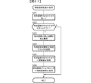
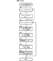
次に、CPU56が実行する普通図柄プロセス処理(ステップS28)を説明する。図8は、普通図柄プロセス処理を示すフローチャートである。普通図柄プロセス処理において、CPU56は、ゲート32(ゲート32Aまたはゲート32B)がオン状態となったこと、すなわち遊技球がゲート32を通過したことを検出すると(ステップS111)、ゲートスイッチ通過処理(ステップS112)を実行する。その後、ステップS100〜S104のいずれかの処理を実行する。なお、以下、ゲート32Aとゲート32Bとをゲート32と総称することがある。
Next, the normal symbol process (step S28) executed by the
ステップS100〜S104の処理は、以下のような処理である。 The processes in steps S100 to S104 are as follows.
普通図柄通常処理(ステップS100):CPU56は、普通図柄の変動を開始することができる状態(例えば普通図柄プロセスフラグの値がステップS100を示す値になっている場合、具体的には、普通図柄表示器10において普通図柄の変動表示が実行されている状態でなく、かつ、可変入賞球装置15の開放状態でない場合)には、ゲート通過記憶数の値を確認する。具体的には、ゲート通過記憶数カウンタのカウント値を確認する。ゲート通過記憶数が0でなければ、当りとするか否か(普通図柄の停止図柄を当り図柄とするか否か)を判定する。そして、普通図柄プロセスフラグの値を普通図柄変動パターン設定処理(ステップS101)を示す値(この例では「1」)に更新する。
Normal symbol normal processing (step S100): The
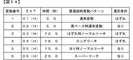
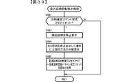
普通図柄変動パターン設定処理(ステップS101):普通図柄の変動表示の変動パターン(図柄変動中の演出態様:変動パターンによって変動時間も特定される。)を、遊技球がゲート32を通過したときに抽出した普通図柄変動パターン判定用乱数(表示用乱数の一つ)の値に応じてあらかじめ定められた複数種類の普通図柄変動パターンの中から選択する。また、判定された変動パターンにもとづいて、普通図柄が変動表示され導出表示されるまでの変動表示時間(普通図柄の変動時間)に相当する値を普通図柄プロセスタイマにセットすることによって普通図柄プロセスタイマをスタートさせる。そして、普通図柄プロセスフラグの値を普通図柄変動処理(ステップS102)に応じた値(この例では「2」)に更新する。 Normal symbol variation pattern setting process (step S101): When the game ball passes the gate 32, the variation pattern of the variation display of the ordinary symbol (the production mode during the symbol variation: the variation time is also specified by the variation pattern). The normal symbol variation pattern determination random number (one of the display random numbers) extracted is selected from a plurality of types of normal symbol variation patterns determined in advance. Also, based on the determined variation pattern, the normal symbol process is set by setting a value corresponding to the variation display time (ordinary symbol variation time) until the normal symbol is variably displayed and derived and displayed in the normal symbol process timer. Start the timer. Then, the value of the normal symbol process flag is updated to a value (“2” in this example) corresponding to the normal symbol variation process (step S102).
普通図柄変動処理(ステップS102):CPU56は、普通図柄プロセスタイマがタイムアウトしたか否か確認し、タイムアウトしていたら、普通図柄表示器10における普通図柄の変動を停止する。また、演出表示装置9における演出図柄の変動表示の停止を指定する演出制御コマンド(図柄確定指定コマンド)を演出制御基板80に送信する。そして、停止期間タイマに普通図柄停止図柄表示時間に相当する値をセットすることによって普通図柄プロセスタイマをスタートさせ、普通図柄プロセスフラグの値を普通図柄停止処理(ステップS103)を示す値(この例では「3」)に更新する。
Normal symbol variation processing (step S102): The
普通図柄停止処理(ステップS103):CPU56は、普通図柄の停止図柄が当り図柄であるか否か判定する。当り図柄でなければ(ハズレ図柄であれば)、普通図柄プロセスフラグの値を普通図柄通常処理(ステップS100)を示す値(この例では「0」)に更新する。普通図柄の停止図柄が当り図柄であれば、電動役物動作期間スタイマに普通電動役物作動時間に相当する値をセットすることによって電動役物動作期間タイマをスタートさせる。また、普通可変入賞球装置(普通電動役物)20を開放する。そして、普通図柄プロセスフラグの値を普通電動役物開放中処理(ステップS104)を示す値(この例では「4」)に更新する。
Normal symbol stop process (step S103): The
普通電動役物開放中処理(ステップS104):CPU56は、普通電動役物(普通可変入賞球装置20)への遊技球の入賞個数(始動入賞口への入賞個数)をカウントする。電動役物動作期間タイマがタイムアウトすると、普通可変入賞球装置20を閉鎖して、普通図柄プロセスフラグの値を普通図柄通常処理(ステップS100)を示す値(この例では「0」)に更新する。
Processing during opening of ordinary electric accessory (step S104): The
図9は、ゲートスイッチ通過処理を示すフローチャートである。ゲートスイッチ通過処理において、CPU56は、ゲート通過記憶カウンタのカウント値(ゲート通過記憶数)が最大値(この例では「4」)に達しているか否か判定する(ステップS115)。最大値に達していなければ、CPU56は、ゲート通過記憶カウンタのカウント値を+1し(ステップS116)、ソフトウェア乱数である普通図柄変動パターン判定用乱数(ランダム2)および普通図柄当り判定用乱数(ランダム3)の値を抽出して、ゲート通過記憶数の値に対応した保存領域(普通図柄判定用バッファ)に格納する(ステップS117)。また、CPU56は、普通図柄保留記憶表示器41の点灯個数を1増やす(ステップS118)。また、CPU56は、ゲート通過記憶数(普通図柄保留記憶数)を示す普通図柄保留記憶数指定コマンドを送信する制御を行う(ステップS119)。なお、ステップS117の処理で普通図柄変動パターン判定用乱数の値を抽出せず、普通図柄変動パターン判定用乱数の値を、普通図柄の変動開始時に(例えば、普通図柄変動パターン設定処理において)抽出するようにしてもよい。
FIG. 9 is a flowchart showing the gate switch passage processing. In the gate switch passage processing, the
また、演出制御用マイクロコンピュータ100に演出制御コマンドを送信する場合には、CPU56は、演出制御コマンドに応じたコマンド送信テーブル(あらかじめROMにコマンド毎に設定されている)のアドレスをポインタにセットする。そして、演出制御コマンドに応じたコマンド送信テーブルのアドレスをポインタにセットして、演出制御コマンド制御処理(ステップS29)において演出制御コマンドを送信する。
When transmitting an effect control command to the
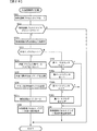
図10は、普通図柄通常処理(ステップS100)を示すフローチャートである。普通図柄通常処理において、CPU56は、変動待機タイマ(図18におけるステップS158の処理でセットされる)がタイムアウトしているか否か判定する(ステップS270)。タイムアウトしていない場合には、変動待機タイマの値を−1して(ステップS278)、普通図柄通常処理を終了する。変動待機タイマが既にタイムアウトしている場合には、ゲート通過記憶数が0であるか否かを判定する(ステップS271)。具体的には、ゲート通過記憶数カウンタのカウント値を確認する。ゲート通過記憶数が0であれば、普通図柄通常処理を終了する。ゲート通過記憶数が0でなければ、CPU56は、ゲート通過記憶数=1に対応する保存領域に格納されている普通図柄当り判定用乱数および普通図柄変動パターン判定用乱数を読み出してRAM55の乱数バッファ領域に格納する(ステップS272)。
FIG. 10 is a flowchart showing the normal symbol normal process (step S100). In the normal symbol normal process, the
そして、CPU56は、ゲート通過記憶数カウンタの値を1減らし、かつ、各保存領域の内容をシフトする(ステップS273)。すなわち、ゲート通過記憶数=n(n=2,3,4)に対応する保存領域に格納されている普通図柄当り判定用乱数値および普通図柄変動パターン判定用乱数値を、ゲート通過記憶数=n−1に対応する保存領域に格納する。よって、各ゲート通過記憶数に対応するそれぞれの保存領域に格納されている普通図柄当り判定用乱数値および普通図柄変動パターン判定用乱数値が抽出された順番は、常に、ゲート通過記憶数=1,2,3,4の順番と一致するようになっている。
Then, the
また、普通図柄保留記憶表示器41において点灯している表示器の数を1減らす(ステップS274)。また、ゲート通過記憶数を1減算することを指定する普通図柄保留記憶数減算指定コマンドを送信する(ステップS275)。なお、普通図柄保留記憶数減算指定コマンドを送信せずに、減算後のゲート通過記憶数を指定するコマンドを送信してもよい。
Further, the number of indicators that are lit in the normal symbol
次いで、CPU56は、読み出した乱数値にもとづいて当りとするかハズレとするか判定する普通図柄当り判定処理を実行する(ステップS276)。
Next, the
そして、CPU56は、普通図柄プロセスフラグの値を普通図柄変動パターン設定処理(ステップS101)を示す値(具体的には「1」)に更新し(ステップS277)、普通図柄通常処理を終了する。
Then, the
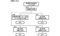
図11は、普通図柄当り判定処理を示すフローチャートである。図11に示すように、普通図柄当り判定処理において、CPU56は、まず、現在の遊技状態が高ベース状態であるか否か確認するために高ベースフラグがセットされているか否かを判定する(ステップS91)。
FIG. 11 is a flowchart showing a normal symbol hit determination process. As shown in FIG. 11, in the normal symbol hit determination process, the
高ベース状態は、遊技球が普通可変入賞球装置20に入賞しやすくなる(すなわち、特別図柄表示器8における変動表示の実行条件が成立しやすくなる)ように制御された遊技状態である。この実施例では、高ベース状態は、時短状態に相当する。高ベース状態である場合には、例えば、高ベース状態でない場合(低ベース状態すなわち通常遊技状態である場合)と比較して、例えば、普通図柄の当り確率が高くなり、その結果、始動入賞しやすくなる。具体的には、普通可変入賞球装置20に遊技球が入賞しやすい状態になる。すなわち、普通可変入賞球装置20が開放状態になりやすい状態であり、低ベース状態に比べて、普通図柄の当り確率が高められている状態と普通可変入賞球装置20の開放回数が多くなっている状態と、開放時間が長くなっている状態と、普通図柄の変動表示時間が短縮されている状態と、のうちで少なくともいずれかの状態であるとともに(普通可変入賞球装置20が開放されやすい状態)、普通図柄の変動表示時間が短縮されている状態(普通図柄の変動表示の実行頻度が多くなっている状態)である。
The high base state is a gaming state that is controlled so that the game ball is likely to win the normal variable winning ball device 20 (that is, the execution condition of the variable display in the special
尚、本実施例では、普通図柄の変動表示結果が当たりとなることで普通可変入賞球装置20を6秒に亘って開放し、該普通可変入賞球装置20へ遊技球が入賞し易くしているが、本発明はこれに限定されず、普通図柄の変動表示結果が当りとなることで更に普通可変入賞球装置20の開放時間を、例えば、6秒、0.1秒、0秒から決定し、開放時間として0.1秒や0秒が決定された場合には、遊技球の普通可変入賞球装置20への入賞を困難または不可能としても良い。
In the present embodiment, the normal variable winning
CPU56は、遊技状態が通常遊技状態であるときは低ベース状態当り判定テーブルを選択し(ステップS92)、遊技状態が高ベース状態(高ベースフラグがセットされているとき)であるときには高ベース状態当り判定テーブルを選択する(ステップS95)。そして、ステップS272の処理で読み出した普通図柄当り判定用乱数の値と当り判定テーブル(低ベース状態判定テーブルまたは高ベース状態当り判定テーブル)に設定されている当り判定値とを比較する(ステップS93)。
When the gaming state is the normal gaming state, the
図12は、普通図柄当り判定テーブル(高ベース状態当り判定テーブルおよび低ベース状態当り判定テーブル)を示す説明図である。図12(A)に示すように、高ベース状態のときに当りに決定される確率は79/80である。図12(B)に示すように、低ベース状態のときに当りに決定される確率は1/80である。よって、遊技状態が低ベース状態のときは低い確率で当りになり、高ベース状態のときは極めて高い確率(この例では、98.75%)で当りになる。 FIG. 12 is an explanatory diagram showing a normal symbol determination table (high base state determination table and low base state determination table). As shown in FIG. 12 (A), the probability determined to be hit in the high base state is 79/80. As shown in FIG. 12 (B), the probability of being determined in the low base state is 1/80. Therefore, when the gaming state is in the low base state, it is a hit with a low probability, and when it is in the high base state, it is a hit with an extremely high probability (98.75% in this example).
CPU56は、ステップS93の処理による比較の結果が当りとなるか否かを判定する(ステップS94)。当りになる場合(普通図柄当り判定用乱数の値がいずれかの当り判定値と一致した場合)には、普通図柄当りフラグをセットしてから(ステップS96)普通図柄当り判定処理を終了し、ハズレになる場合には、そのまま普通図柄当り判定処理を終了する。
The
図13は、普通図柄プロセス処理における普通図柄変動パターン設定処理(ステップS102)を示すフローチャートである。普通図柄変動パターン設定処理において、CPU56は、まず、普通図柄当りフラグがセットされているか否か判定する(ステップS131)。普通図柄当りフラグがセットされている場合には、CPU56は、現在の遊技状態が高ベース状態であるか否か確認するために高ベースフラグがセットされているか否か判定する(ステップS132)。遊技状態が高ベース状態でなく低ベース状態である場合には、低ベース当り変動パターン判定テーブルを選択する(ステップS133)。
FIG. 13 is a flowchart showing a normal symbol variation pattern setting process (step S102) in the normal symbol process. In the normal symbol variation pattern setting process, the
遊技状態が高ベース状態であるとき(高ベースフラグがセットされているとき)は、高ベース状態において当りになるときに使用する高ベース当り変動パターン判定テーブルを選択する(ステップS134)。 When the gaming state is the high base state (when the high base flag is set), a high base per-fluctuation pattern determination table to be used when winning in the high base state is selected (step S134).
図14は、本実施例で用いられる普通図柄変動パターンを示す説明図である。図14において、「EXT」とは、2バイト構成の演出制御コマンドにおける2バイト目のEXTデータを示す。また、「時間」は普通図柄の変動時間(識別情報の変動表示期間)を示す。 FIG. 14 is an explanatory diagram showing a normal symbol variation pattern used in this embodiment. In FIG. 14, “EXT” indicates EXT data of the second byte in the effect control command having a two-byte structure. “Time” indicates a normal symbol variation time (a variation display period of identification information).
この例では、普通図柄の各変動パターンは、演出図柄の停止図柄が「ハズレ図柄」になる場合の普通図柄変動パターン(ハズレ専用の普通図柄変動パターン)と、演出図柄の停止図柄が「当り図柄」になる場合の普通図柄変動パターン(当り専用の普通図柄変動パターン)とに区別されている。 In this example, each variation pattern of the normal symbol is the normal symbol variation pattern when the stop symbol of the production symbol is “losing symbol” (ordinary symbol variation pattern exclusively for the loss), and the stop symbol of the production symbol is “winning symbol” ”And the normal symbol variation pattern (ordinary normal variation pattern).
ハズレ専用の普通図柄変動パターンとして、リーチを伴わない通常変動の普通図柄変動パターンと、ハズレ時ノーマルリーチ(単純なリーチ態様)の普通図柄変動パターンと、ロングリーチを伴う普通図柄変動パターンとがある。 As the normal symbol variation pattern dedicated to losing, there are a normal symbol variation pattern with normal variation without reach, a normal symbol variation pattern with normal reach (simple reach mode), and a normal symbol variation pattern with long reach.
当り専用の普通図柄変動パターンとして、高ベース状態のときにのみ使用される高ベース時通常変動パターンと、通常遊技状態のときにのみ使用される当り時ノーマルリーチの変動パターンと、通常遊技状態のときにのみ使用されるスーパーリーチの変動パターンとがある。 The normal variation pattern at the time of high base used only in the high base state, the variation pattern of normal reach at the time of hit used only in the normal gaming state, and the normal gaming state There are fluctuation patterns of super reach that are used only in
低ベース当り変動パターン判定テーブルには、当りのときに選択される普通図柄変動パターン(図14における「05(H)」,「06(H)」の変動パターン)のそれぞれに対応する複数の判定値が割り当てられている。 The low base variation pattern determination table includes a plurality of determinations corresponding to the normal symbol variation patterns (variation patterns “05 (H)” and “06 (H)” in FIG. 14) selected at the time of winning. A value has been assigned.
高ベース当り変動パターン判定テーブルには、高ベース状態において当りのときにのみ選択される普通図柄変動パターン(図14における「02(H)」)に対応する判定値のみが設定されている。 In the high base variation pattern determination table, only the determination value corresponding to the normal symbol variation pattern (“02 (H)” in FIG. 14) selected only when winning in the high base state is set.
また、ステップS131において、普通図柄当りフラグがセットされていないときは、CPU56は、ハズレになるときに使用するハズレ用変動パターン判定テーブルを選択する(ステップS135)。
If the normal symbol flag is not set in step S131, the
ハズレ用変動パターン判定テーブルには、ハズレのときにのみ選択される普通図柄変動パターン(図14における「01(H)」,「03(H)」,「04(H)」)のそれぞれに対応する複数の判定値が割り当てられている。 The variation pattern determination table for loss corresponds to each of the normal symbol variation patterns (“01 (H)”, “03 (H)”, and “04 (H)” in FIG. 14) selected only at the time of the loss. A plurality of judgment values are assigned.
そして、CPU56は、乱数格納バッファに格納されている普通図柄変動パターン判定用乱数の値にもとづいて、ステップS133,S134,S135の処理で選択した変動パターン判定テーブルを用いて普通図柄の変動パターンを決定する(ステップS136)。なお、CPU56は、ハズレにする場合に、低ベース状態において、ハズレ用変動パターン判定テーブルを選択し、高ベース状態であるときには、普通図柄変動パターンを「通常変動」の変動パターンに決定する。
Then, the
また、本実施例では、ハズレにすることに決定された場合に、普通図柄変動パターン判定用乱数とハズレ用変動パターン判定テーブルとにもとづいて普通図柄の変動パターンが判定されるが、ハズレにすることに決定された場合には、リーチ決定用乱数を使用して、リーチ決定用乱数の値にもとづいてリーチにするか否か決定するようにしてもよい。 Also, in this embodiment, when it is decided to lose, the normal symbol fluctuation pattern is determined based on the normal symbol fluctuation pattern determination random number and the loss fluctuation pattern determination table. If it is determined, the reach determination random number may be used to determine whether or not to reach based on the value of the reach determination random number.
また、本実施例では、普通図柄変動パターンは、演出図柄の停止図柄が「ハズレ図柄」になる場合にのみ使用されるハズレ専用の普通図柄変動パターンと、演出図柄の停止図柄が「当り図柄」になる場合にのみ使用される当り専用の普通図柄変動パターンとに区別されているが、「ハズレ図柄」になる場合にも「当り図柄」になる場合にも使用される普通図柄変動パターン(例えば、ロングリーチを伴う変動パターンおよびスーパーリーチの変動パターン)があるようにしてもよい。 Also, in this embodiment, the normal symbol variation pattern is a normal symbol variation pattern dedicated to losing, which is used only when the stop symbol of the production symbol is `` losing symbol '', and the stop symbol of the production symbol is `` hit symbol '' It is distinguished from the normal symbol fluctuation pattern dedicated to hits that is used only when the , A fluctuation pattern with long reach and a super reach fluctuation pattern).
次いで、CPU56は、普通図柄プロセスタイマに、普通図柄変動パターンで特定される普通図柄の変動時間に相当する値をセットする(ステップS137)。また、CPU56は、ステップS136の処理で決定した普通図柄変動パターンに応じた普通図柄変動パターンコマンドを送信する制御を行う(ステップS138)。
Next, the
そして、普通図柄プロセスフラグの値を普通図柄変動処理(ステップS102)に対応した値(具体的には「2」)に更新する(ステップS139)。 Then, the value of the normal symbol process flag is updated to a value (specifically “2”) corresponding to the normal symbol variation process (step S102) (step S139).
図15は、普通図柄変動処理(ステップS102)を示すフローチャートである。普通図柄変動処理において、CPU56は、普通図柄プロセスタイマの値が0になったかどうか、すなわち、普通図柄プロセスタイマがタイムアウトしたか否か判定する(ステップS141)。普通図柄プロセスタイマがタイムアウトしていなければ、CPU56は、普通図柄プロセスタイマの値を−1し(ステップS142)、普通図柄変動処理を終了する。
FIG. 15 is a flowchart showing the normal symbol variation process (step S102). In the normal symbol variation process, the
普通図柄プロセスタイマがタイムアウトしたとき、すなわち、普通図柄の変動時間が経過したときは、CPU56は、普通図柄表示器10における普通図柄の変動を停止させる(ステップS143)。そして、CPU56は、図柄停止指定コマンドを演出制御用マイクロコンピュータ100に送信する制御を行う(ステップS144)。
When the normal symbol process timer times out, that is, when the normal symbol change time has elapsed, the
また、CPU56は、停止期間タイマに普通図柄停止図柄表示時間をセットする(ステップS145)。そして、CPU56は、普通図柄プロセスフラグの値を普通図柄停止処理(ステップS103)を示す値(具体的には「3」)に更新し(ステップS146)、普通図柄変動処理を終了する。
Further, the
図16は、普通図柄停止処理(ステップS103)を示すフローチャートである。普通図柄停止処理において、CPU56は、停止期間タイマの値が0になったかどうか、すなわち、停止期間タイマがタイムアウトしたか否か判定する(ステップS151)。停止期間タイマがタイムアウトしていなければ、停止期間タイマの値を−1し(ステップS152)、普通図柄停止処理を終了する。
FIG. 16 is a flowchart showing the normal symbol stop process (step S103). In the normal symbol stop process, the
停止期間タイマがタイムアウトしたとき、すなわち、普通図柄停止図柄表示時間が経過したときは、CPU56は、普通図柄当りフラグがセットされているか否か判定する(ステップS153)。
When the stop period timer times out, that is, when the normal symbol stop symbol display time has elapsed, the
普通図柄当りフラグがセットされているときは、CPU56は、電動役物動作期間タイマに普通電動役物作動時間(例えば、6秒)に相当する値をセットする(ステップS154)。なお、普通電動役物作動時間を、遊技状態が通常状態のときと確変状態のときとで異なる時間にしてもよい。
When the normal symbol hit flag is set, the
また、CPU56は、普通可変入賞球装置(普通電動役物)20を開放状態にし(ステップS155)、入賞個数カウンタの値を0にクリアしておく(ステップS156)。
Further, the
そして、普通図柄プロセスフラグの値を普通電動役物開放中処理(ステップS104)を示す値(具体的には「4」)に更新し(ステップS157)、普通図柄停止処理を終了する。 Then, the value of the normal symbol process flag is updated to a value (specifically, “4”) indicating the process for releasing the normal electric accessory (step S104) (step S157), and the normal symbol stop process is terminated.
ステップS153において、普通図柄当りフラグがセットされていないと判定したときは、CPU56は、変動待機タイマに次回変動待機時間(例えば、2.0秒)に相当する値をセットする(ステップS158)。そして、普通図柄プロセスフラグの値を普通図柄通常処理(ステップS100)を示す値(具体的には「0」)に更新する(ステップS159)。
If it is determined in step S153 that the normal symbol per flag is not set, the
図17は、普通電動役物開放中処理(ステップS104)を示すフローチャートである。普通電動役物開放中処理において、CPU56は、先ず、普通図柄プロセスタイマの値を−1する(ステップS162)。
FIG. 17 is a flowchart showing the process during the opening of the ordinary electric accessory (step S104). In the process for releasing the ordinary electric accessory, the
そしてCPU56は、始動口スイッチ23がオンとなったか否か、つまり、始動口スイッチ23にて遊技球が検出されたか否かを判定する(ステップS163)。始動口スイッチ23がオンとなっていない場合はステップS168に移行し、始動口スイッチ23がオンとなっている場合には、入賞個数カウンタの値を+1する(ステップS164)。そして、入賞個数カウンタの値が7になったか否か判定する(ステップS165)。入賞個数カウンタの値が7でない場合にはステップS168に移行し、入賞個数カウンタの値が7になった場合には、電動役物動作期間タイマをクリアする(ステップS165a)。そして、CPU56は、普通可変入賞球装置(普通電動役物)20を閉鎖状態にし(ステップS166)、普通図柄当りフラグをクリアする(ステップS166a)。更に、CPU56は、変動待機タイマに次回変動待機時間(例えば、2.0秒)に相当する値をセットする(ステップS166b)。
Then, the
そして、普通図柄プロセスフラグの値を普通図柄通常処理(ステップS100)を示す値(具体的には「0」)に更新し(ステップS167)、普通電動役物開放中処理を終了する。 Then, the value of the normal symbol process flag is updated to a value (specifically, “0”) indicating the normal symbol normal process (step S100) (step S167), and the process of releasing the normal electric accessory is ended.
尚、ステップS163において始動口スイッチ23がオンとなっていない場合、またはステップS165において入賞個数カウンタの値が7でない場合、ステップS168では、電動役物動作期間タイマがタイマアウトしているか否かを判定する(ステップS168)。電動役物動作期間タイマがタイマアウトしていない場合は、普通電動役物開放中処理を終了し、電動役物動作期間タイマがタイマアウトしている場合は、前述したステップS166〜S167の制御を実行して普通電動役物開放中処理を終了する。
If the
次に、特別図柄および大入賞口の制御を説明する。図18は、主基板31に搭載される遊技制御用マイクロコンピュータ560(具体的には、CPU56)が実行する特別図柄プロセス処理(ステップS27)のプログラムの一例を示すフローチャートである。上述したように、特別図柄プロセス処理では特別図柄表示器8および大入賞口を制御するための処理が実行される。特別図柄プロセス処理において、CPU56は、ステップS300〜S307のうちのいずれかの処理を行う。
Next, the control of the special symbol and the special winning opening will be described. FIG. 18 is a flowchart showing an example of a special symbol process (step S27) program executed by the game control microcomputer 560 (specifically, the CPU 56) mounted on the main board 31. As described above, in the special symbol process, a process for controlling the
ステップS300〜S307の処理は、以下のような処理である。 The processes in steps S300 to S307 are as follows.
特別図柄通常処理(ステップS300):特別図柄プロセスフラグの値が0であるときに実行される。CPU56は、特別図柄の変動表示が開始できる状態になると、大当りにするか否か(特別図柄の変動表示の表示結果を大当りとするか否か)を判定する。大当りにする場合には、大当りフラグをセットし、大当りの種別を決定する。そして、内部状態(特別図柄プロセスフラグ)をステップS300+に応じた値(この例では「1」)に更新する。
Special symbol normal processing (step S300): Executed when the value of the special symbol process flag is zero. When the special symbol variation display can be started, the
変動パターン設定処理(ステップS300+)は、特別図柄プロセスフラグの値が“1”のときに実行される。CPU56は、特別図柄の変動表示結果が大当りであるか否かや、遊技状態に応じて特別図柄の変動パターンを決定する。そして、内部状態(特別図柄プロセスフラグ)をステップS301に応じた値(この例では「2」)に更新する。
The variation pattern setting process (step S300 +) is executed when the value of the special symbol process flag is “1”. The
特別図柄変動開始処理(ステップS301):特別図柄プロセスフラグの値が2であるときに実行される。特別図柄の変動表示が開始されてから導出表示されるまでの変動表示時間(変動時間)に相当する値を特別図柄プロセスタイマにセットすることによって特別図柄プロセスタイマをスタートさせる。尚、本実施例では、特別図柄の変動時間は図24及び図25に示すように複数パターンが用意されている。そして、内部状態(特別図柄プロセスフラグ)をステップS302に応じた値(この例では「3」)に更新する。 Special symbol variation start processing (step S301): This is executed when the value of the special symbol process flag is 2. The special symbol process timer is started by setting in the special symbol process timer a value corresponding to the variable display time (variation time) from the start of the special symbol variation display to the derivation display. In the present embodiment, a plurality of patterns are prepared for the variation time of the special symbol as shown in FIGS. Then, the internal state (special symbol process flag) is updated to a value (“3” in this example) corresponding to step S302.
特別図柄変動中処理(ステップS302):特別図柄プロセスフラグの値が3であるときに実行される。特別図柄変動開始処理でセットされた変動時間が経過(ステップS301でセットされた特別図柄プロセスタイマがタイムアウト)すると、内部状態(特別図柄プロセスフラグ)をステップS303に応じた値(この例では「4」)に更新する。 Special symbol changing process (step S302): This process is executed when the value of the special symbol process flag is 3. When the variation time set in the special symbol variation start process has elapsed (the special symbol process timer set in step S301 has timed out), the internal state (special symbol process flag) is set to a value corresponding to step S303 (in this example, “4”). )).
特別図柄停止処理(ステップS303):特別図柄プロセスフラグの値が4であるときに実行される。特別図柄表示器8における変動表示を停止して停止図柄を表示させる。また、大当りフラグがセットされているか否か判定する。大当りフラグがセットされている場合には、内部状態(特別図柄プロセスフラグ)をステップS304に応じた値(この例では「5」)に更新する。大当りフラグがセットされていない場合には、内部状態(特別図柄プロセスフラグ)をステップS300に応じた値(この例では「0」)に更新する。
Special symbol stop process (step S303): executed when the value of the special symbol process flag is 4. The variable display on the
大当り表示処理(ステップS304):特別図柄プロセスフラグの値が5であるときに実行される。CPU56は、演出制御用マイクロコンピュータ100が大当りの発生を報知するための制御を行っている時間が経過したら、内部状態(特別図柄プロセスフラグ)をステップS305に対応した値(この例では「6」)に更新する。
Big hit display process (step S304): This process is executed when the value of the special symbol process flag is 5. When the time during which the
大入賞口開放前処理(ステップS305):特別図柄プロセスフラグの値が6であるときに実行される。大当り表示時間が経過したときに、大入賞口を開放する制御を開始する。具体的には、ソレノイド21を駆動して特別可変入賞球装置15を開状態にして大入賞口を開放する。また、ラウンド中タイマに大入賞口開放中処理の実行時間(ラウンド時間)を設定し、内部状態(特別図柄プロセスフラグ)をステップS306に応じた値(この例では「7」)に更新する。
Preliminary winning opening process (step S305): This process is executed when the value of the special symbol process flag is 6. When the big hit display time has elapsed, the control for opening the big prize opening is started. Specifically, the
大入賞口開放中処理(ステップS306):特別図柄プロセスフラグの値が7であるときに実行される。大入賞口の閉成条件の成立を判定する処理等を行う。大入賞口の閉成条件が成立したら、ソレノイド21を駆動して特別可変入賞球装置15を閉状態にして大入賞口を閉鎖する。全てのラウンドを終えた場合には、内部状態(特別図柄プロセスフラグ)をステップS307に対応した値(この例では8)に更新する。
Large winning opening open process (step S306): This process is executed when the value of the special symbol process flag is 7. Processing for determining whether the closing condition for the big prize opening is satisfied. When the closing condition of the special winning opening is established, the
大当り終了処理(ステップS307):特別図柄プロセスフラグの値が8であるときに実行される。大当り遊技状態が終了したことを遊技者に報知する表示制御を演出制御用マイクロコンピュータ100に行わせるための制御を行う。また、遊技状態を示すフラグ(例えば、確変フラグや高ベースフラグ)をセットする処理を行う。そして、内部状態(特別図柄プロセスフラグ)をステップS300に対応した値(この例では「0」)に更新する。
Big hit end process (step S307): This process is executed when the value of the special symbol process flag is 8. Control for causing the
図19は、特別図柄プロセス処理における特別図柄通常処理(ステップS300)を示すフローチャートである。特別図柄通常処理において、CPU56は、特別図柄の変動を開始することができる変動開始条件が成立しているか否か(特別図柄プロセスフラグの値がステップS300を示す値(例えば「0」)になっている場合、つまり、特別図柄表示器8において特別図柄の変動表示がなされていない状態であり、かつ、大当り遊技中でもない場合)を判定する(ステップS51)。変動開始条件が成立していない場合は特別図柄通常処理を終了し、変動開始条件が成立している場合は、始動口スイッチ23がオンしたか否かを判定する(ステップS52)。尚、本実施例のパチンコ遊技機1においては、普通可変入賞球装置20の開放時間は最大6秒であるのに対し、遊技状態が低確低ベース状態である場合は、特別図柄の変動表示時間は一義的に10秒(図24及び図25参照)となっているため、遊技状態が低確低ベース状態である場合の特別図柄の変動表示は、普通可変入賞球装置20に最初に入賞した遊技球に基づく1回のみとなっている。
FIG. 19 is a flowchart showing the special symbol normal process (step S300) in the special symbol process. In the special symbol normal process, the
CPU56は、始動口スイッチ23がオン状態でない場合は特別図柄通常処理を終了し、始動口スイッチ23がオン状態である場合は、乱数回路503から大当り判定用乱数であるランダムR、大当り種別決定用乱数であるランダム1、特別図柄変動パターン判定用乱数であるランダム5となる値を抽出する(ステップS53)。そして、CPU56は、大当り判定処理を実行する(ステップS54)。
When the
図20は、大当り判定処理を示すフローチャートである。図20に示すように、大当り判定処理において、CPU56は、まず、現在の遊技状態は、特別図柄の変動表示結果として大当りとなる大当り確率が通常状態(低確率状態)の大当り確率(本実施例では1/4)よりも高い確率(本実施例では99/100)に制御されている確変状態(高確率状態)であるか否かを確認するために確変フラグがセットされているか否か判定する(ステップS81)。
FIG. 20 is a flowchart showing the big hit determination process. As shown in FIG. 20, in the jackpot determination process, the
遊技状態が通常状態である場合(確変フラグがセットされていないとき)には、CPU56は、通常状態のときの大当り判定で使用する通常時大当り判定テーブルを選択し(ステップS82)、ステップS53で読み出したランダムR(大当り判定用乱数)の値と通常時大当り判定テーブルに設定されている大当り判定値とを比較して大当りにするか否か判定する。大当り判定用乱数の値がいずれかの大当り判定値と一致したら大当りにすることに判定する。また、CPU56は、確変フラグがセットされている場合には、確変時大当り判定テーブルを選択し(ステップS84)、ステップS53で読み出した大当り判定用乱数の値と確変時大当り判定テーブルに設定されている大当り判定値とを比較する(ステップS85)。
When the gaming state is the normal state (when the probability variation flag is not set), the
そして、CPU56は、ステップS83またはステップS84におけるランダムRの値と大当り判定テーブルにおける判定値との比較結果として、ランダムRの値が大当り判定テーブルにおける判定値内の値であるか否か、つまり、大当りにすることに判定するか否かを判定する(ステップS86)。大当りにすることに決定した場合には、大当りフラグをセットして(ステップS87)大当り判定処理を終了する一方、大当りにすることに決定していない、つまり、ハズレにすることに決定した場合には、大当り判定処理を終了する。
Then, the
図21(A)は、通常時大当り判定テーブルを示す説明図であり、図21(B)は確変時大当り判定テーブルを示す説明図である。図21(A)に示すように、通常時大当り判定テーブルには、大当り判定値として0〜16383が設定されており、ハズレ判定値として16384〜65535が設定されている。大当り判定用乱数であるランダムRの値が取りうる範囲0〜65535であるから、通常遊技状態のときに大当りに決定される確率(特別図柄の当選確率)は約1/4(25%)である。 FIG. 21A is an explanatory diagram showing a normal jackpot determination table, and FIG. 21B is an explanatory diagram showing a probability change jackpot determination table. As shown in FIG. 21A, in the normal big hit determination table, 0-16383 is set as a big hit determination value, and 16384-65535 is set as a loss determination value. Since the value of random R, which is a jackpot determination random number, is in the range of 0 to 65535, the probability of winning a jackpot in the normal gaming state (special symbol winning probability) is about 1/4 (25%) is there.
図21(B)に示すように、確変時大当り判定テーブルには、大当り判定値として0〜64880が設定されており、ハズレ判定値として64881〜65535が設定されている。従って、確変状態のときに大当りに決定される確率(特別図柄の当選確率)は約99/100(99%)である。尚、確変状態においては、大当り判定用乱数であるランダムRの値が取りうる範囲0〜65535を全て大当り判定値に設定することで、普通可変入賞球装置20への視導入が常に大当りにするようにしても良い。
As shown in FIG. 21 (B), 0 to 64880 is set as the big hit determination value and 64881 to 65535 is set as the loss determination value in the probability change big hit determination table. Accordingly, the probability that the jackpot is determined in the probability variation state (the winning probability of the special symbol) is about 99/100 (99%). In the probability variation state, the
以上のように、本実施例では、遊技状態が通常状態のときは低い確率(25%の確率)で大当りになり、遊技状態が確変状態のときは高い確率(99%の確率)で大当りになる。 As described above, in this embodiment, when the gaming state is the normal state, the big hit is made with a low probability (25% probability), and when the gaming state is the probable state, the big hit is made with a high probability (99% probability). Become.
なお、本実施例では、確変状態のときに大当りに決定される確率(特別図柄の当選確率)は99%であるが、確変状態のときに大当りに決定される確率が100%である場合は、ステップS84,S85の処理を実行しないようにしてもよい。さらに、確変フラグがセットされているときには、直ちに大当りフラグをセットするようにしてもよい。 In this embodiment, the probability that the jackpot is determined in the probability variation state (special symbol winning probability) is 99%, but the probability that the jackpot is determined in the probability variation state is 100%. The processes in steps S84 and S85 may not be executed. Further, when the probability variation flag is set, the big hit flag may be set immediately.
大当り判定処理を実行した後、図21に示すように、CPU56は、大当り判定処理において大当りフラグがセットされたか否か判定する(ステップS55)。大当りフラグがセットされていない場合、すなわち、ハズレに決定された場合には、ステップS63に移行する。
After executing the big hit determination process, as shown in FIG. 21, the
大当りフラグがセットされている場合には、CPU56は、大当り回数カウンタの値が1であるか否かを判定する(ステップS56b)。
When the big hit flag is set, the
大当り回数カウンタの値が1でない場合、CPU56は、ステップS53において抽出したランダム1と、大当り種別決定テーブル(大当り回数カウンタ≠1)に基づいて大当り種別を決定する(ステップS56c)。
When the value of the big hit number counter is not 1, the
図22(A)は、大当り種別決定テーブル(大当り回数カウンタ≠1)を示す説明図である。図22(A)に示すように、大当り種別決定テーブル(大当り回数カウンタ≠1)では、第1大当りの決定値として0〜37が設定されており、第2−1大当りの決定値として38が設定されており、第2−2大当りの決定値として39が設定されている。このため、大当り種別決定用乱数であるランダム1と大当り種別決定テーブル(大当り回数カウンタ≠1)に基づいて大当り種別を決定する場合は、第1大当りに決定される確率は95%であり、第2−1大当り・第2−2大当りに決定される確率は共に2.5%である。ステップS56cにおいて大当り種別決定後、CPU56は、ステップS60に移行する。
FIG. 22A is an explanatory diagram showing a big hit type determination table (big hit number counter ≠ 1). As shown in FIG. 22 (A), in the big hit type determination table (big hit count counter ≠ 1), 0 to 37 are set as the first big hit decision value, and 38 is set as the 2-1 big hit decision value. 39 is set as the determined value for the 2-2 big hit. For this reason, when determining the big hit type based on the random 1 which is the big hit type determining random number and the big hit type determining table (hit number counter ≠ 1), the probability of determining the first big hit is 95%, The probability determined for 2-1 jackpot and 2-2 jackpot is 2.5%. After determining the jackpot type in step S56c, the
ステップS56bにおいて大当り回数カウンタが1である場合は、CPU56は、ステップS53において抽出したランダム1と、大当り種別決定テーブル(大当り回数カウンタ=1)に基づいて大当り種別を決定する(ステップS56d)。
When the big hit number counter is 1 in step S56b, the
図22(B)は、大当り種別決定テーブル(大当り回数カウンタ=1)を示す説明図である。図22(B)に示すように、大当り種別決定テーブル(大当り回数カウンタ=1)では、第2−A大当りの決定値として0〜19が設定されており、第2−B大当りの決定値として20〜39が設定されている。このため、大当り種別決定用乱数であるランダム1と大当り種別決定テーブル(大当り回数カウンタ=1)に基づいて大当り種別を決定する場合は、第2−A大当り・第2−B大当りに決定される確率は共に50%である。 FIG. 22B is an explanatory diagram showing a big hit type determination table (big hit number counter = 1). As shown in FIG. 22B, in the big hit type determination table (big hit number counter = 1), 0-19 are set as the determined values for the second-A big hit, and the determined values for the second-B big hit are 20 to 39 are set. For this reason, when determining the big hit type based on random 1 which is a big hit type determining random number and the big hit type determination table (big hit number counter = 1), it is determined as the second-A big hit and the second-B big hit. Both probabilities are 50%.
ステップS56dにおいて大当り種別決定後、CPU56は、ステップS60に移行する。
After determining the big hit type in step S56d, the
ステップS60では、CPU56は、ステップS56c、ステップS56d、ステップS56gのいずれかで決定された大当り種別をRAM55の所定の記憶領域に記憶し、ステップS63に移行する。尚、ステップS60において、既にRAM55の所定の記憶領域に前回の大当り種別が記憶されている場合は、該前回の大当り種別を今回の大当りにおいてステップS56c、ステップS56dのいずれかで決定された大当り種別に更新する。
In step S60, the
そして、ステップS63では、CPU56は、特別図柄の停止図柄を決定する。ただし、本実施例では、大当り図柄は大当り種別に応じて各々一種類しか設けられていないので、大当りの種別が決定されることによって、大当り図柄も自動的に決定されている。具体的には、図22に示すように、「1」が第1大当り図柄であり、「2」が第2−1大当り図柄であり、「3」が第2−2大当り図柄であり、「4」が第2−A大当り図柄であり、「5」が第2−B大当り図柄である。なお、大当り図柄として、大当りの種別に応じて一種類の停止図柄を使用するのではなく、複数種類の図柄から選択するようにしてもよい。 And in step S63, CPU56 determines the stop symbol of a special symbol. However, in the present embodiment, only one type of jackpot symbol is provided according to the jackpot type, so that the jackpot symbol is automatically determined by determining the jackpot type. Specifically, as shown in FIG. 22, “1” is the first big hit symbol, “2” is the 2-1 big hit symbol, “3” is the 2-2 big hit symbol, "4" is the 2nd-A jackpot symbol, and "5" is the 2nd-B jackpot symbol. It should be noted that instead of using one type of stop symbol according to the type of jackpot, the jackpot symbol may be selected from a plurality of types of symbols.
また、ハズレ図柄も一種類「0」しか設けられていないので、ハズレに決定されたことによって、ハズレ図柄も自動的に決定される。 Also, since only one type of “0” is provided for the lost symbol, the lost symbol is automatically determined when it is determined to be lost.
なお、本実施例では、まず大当りとするか否かを決定し、大当りとすることに決定した後に大当り種別を決定する場合を示したが、大当りとするか否かの決定と大当り種別の決定方法は、本実施例で示したものに限られない。例えば、各々の大当りの種別のそれぞれに決定値が割り当てられたテーブルを用意し、そのテーブルにもとづいて、いずれかの大当りの種別にすることに決定された場合には、大当りとすることに決定されたことにしてもよい。つまり、大当りとするか否かと大当りの種別とを同時に決定してもよい。また、あらかじめ特別図柄の停止図柄と大当り種別とを対応付けたテーブルを用意しておき、大当り種別決定用乱数にもとづいてまず特別図柄の停止図柄を決定すると、その決定結果にもとづいて対応する大当り種別も決定されるように構成してもよい。 In this embodiment, it is determined whether or not the jackpot is first determined, and then the jackpot type is determined after the jackpot is determined. However, whether the jackpot is determined or the jackpot type is determined. The method is not limited to that shown in this embodiment. For example, a table in which a decision value is assigned to each jackpot type is prepared, and if it is determined to be any jackpot type based on the table, it is determined to be a jackpot It may be done. That is, whether or not to make a big hit and the type of big hit may be determined simultaneously. In addition, a table in which a special symbol stop symbol and a jackpot type are associated in advance is prepared, and when a special symbol stop symbol is first determined based on the random number for determining the big hit type, the corresponding jackpot is determined based on the determination result. You may comprise so that a classification may also be determined.
その後、CPU56は、特別図柄プロセスフラグの値を変動パターン設定処理(ステップS300+)に対応した値(例えば「1」)に更新する(ステップS64)。そして、特別図柄通常処理を終了する。
Thereafter, the
図23は、変動パターン設定処理として、図18のステップS300+にて実行される処理の一例を示すフローチャートである。図23に示す変動パターン設定処理において、CPU56は、まず、大当りフラグがオンであるか否かを判定する(ステップS281)。そして、大当りフラグがオンであれば、高ベースフラグがセットされているか否かを判定する(ステップS282)。尚、本実施例における高ベースフラグとは、後述する大当り終了処理において、大当り種別が第2−1大当りである場合にセットされる第1高ベースフラグと、大当り種別が第1大当り、第2−2大当り、第2−A大当りである場合にセットされる第2高ベースフラグとの双方を含んでいる。更に、後述する第1低確高ベースとは、第1高ベースフラグがセットされている状態の低確高ベース状態を指し、第2低確高ベースとは、第2高ベースフラグがセットされている状態の低確高ベース状態を指す。
FIG. 23 is a flowchart illustrating an example of a process executed in step S300 + of FIG. 18 as the variation pattern setting process. In the variation pattern setting process shown in FIG. 23, the
高ベースフラグがセットされていない場合は、図24(A)に示す低確低ベース時の大当り変動パターン判定テーブルを選択し(ステップS284)、ステップS296aに移行する。また、高ベースフラグがセットされている場合は、更に確変フラグがセットされているか否かを判定する(ステップS286)。確変フラグがセットされている場合は、図24(D)に示す高確高ベース時の大当り変動パターン判定テーブルを選択し(ステップS288)、ステップS296aに移行する。 If the high base flag is not set, the big hit variation pattern determination table at the time of low probability low base shown in FIG. 24A is selected (step S284), and the process proceeds to step S296a. If the high base flag is set, it is further determined whether or not the probability variation flag is set (step S286). When the probability variation flag is set, the big hit variation pattern determination table at the time of high accuracy and base shown in FIG. 24D is selected (step S288), and the process proceeds to step S296a.
また、確変フラグがセットされていない場合は、更にセットされている高ベースフラグが第1高ベースフラグであるか否かを判定する(ステップS287a)。高ベースフラグが第1高ベースフラグである場合は、図24(B)に示す第1低確高ベース時の大当り変動パターン判定テーブルを選択して(ステップS287b)ステップS296aに移行し、高ベースフラグが第1高ベースフラグではない場合、つまり、高ベースフラグが第2高ベースフラグである場合は、図24(C)に示す第2低確高ベース時の大当り変動パターン判定テーブルを選択して(ステップS287c)ステップS296aに移行する。 If the probability variation flag is not set, it is further determined whether or not the set high base flag is the first high base flag (step S287a). When the high base flag is the first high base flag, the big hit fluctuation pattern determination table at the time of the first low-accuracy high base shown in FIG. 24B is selected (step S287b), and the process proceeds to step S296a. When the flag is not the first high base flag, that is, when the high base flag is the second high base flag, the big hit fluctuation pattern determination table at the time of the second low accuracy high base shown in FIG. 24C is selected. (Step S287c), the process proceeds to step S296a.
ステップS281において、大当りフラグがオンでない場合は、CPU56は、高ベースフラグがセットされているか否かを判定する(ステップS289)。
When the big hit flag is not on in step S281, the
高ベースフラグがセットされていない場合は、図25(A)に示す低確低ベース時のハズレ変動パターン判定テーブルを選択し(ステップS291)、ステップS296aに移行する。また、高ベースフラグがセットされている場合は、更に確変フラグがセットされているか否かを判定する(ステップS293)。確変フラグがセットされている場合は、図25(D)に示す高確高ベース時のハズレ変動パターン判定テーブルを選択し(ステップS295)、ステップS296aに移行する。 If the high base flag is not set, the loss variation pattern determination table at the time of low probability low base shown in FIG. 25A is selected (step S291), and the process proceeds to step S296a. If the high base flag is set, it is further determined whether or not the probability variation flag is set (step S293). When the probability variation flag is set, the loss variation pattern determination table at the time of high accuracy and base shown in FIG. 25D is selected (step S295), and the process proceeds to step S296a.
また、確変フラグがセットされていない場合は、更にセットされている高ベースフラグが第1高ベースフラグであるか否かを判定する(ステップS294a)。高ベースフラグが第1高ベースフラグである場合は、図25(B)に示す第1低確高ベース時のハズレ変動パターン判定テーブルを選択して(ステップS294b)ステップS296aに移行し、高ベースフラグが第1高ベースフラグではない場合、つまり、高ベースフラグが第2高ベースフラグである場合は、図25(C)に示す第2低確高ベース時のハズレ変動パターン判定テーブルを選択して(ステップS294c)ステップS296aに移行する。 If the probability variation flag is not set, it is further determined whether or not the set high base flag is the first high base flag (step S294a). When the high base flag is the first high base flag, the loss variation pattern determination table at the time of the first low accuracy high base shown in FIG. 25B is selected (step S294b), and the process proceeds to step S296a, and the high base flag is set. When the flag is not the first high base flag, that is, when the high base flag is the second high base flag, the loss variation pattern determination table for the second low accuracy high base shown in FIG. 25C is selected. (Step S294c), the process proceeds to step S296a.
そして、ステップS296aでは、CPU56は、ステップS53にて抽出されたランダム5と、ステップS284、ステップS288、ステップS287b、ステップS287c、ステップS291、ステップS295、ステップS294b、ステップS294cのいずれかで選択された特別図柄の変動パターン判定テーブルに基づいて、特別図柄変動パターンを決定する(ステップS296a)。
In step S296a, the
図24(A)は、低確低ベース時の大当り変動パターン判定テーブルを示す説明図である。図24(A)に示すように、低確低ベース時の大当り変動パターン判定テーブルでは、変動時間が10秒である特別図柄変動パターンPA1の判定値として0〜999が設定されており、変動時間が150秒である特別図柄変動パターンPA2と変動時間が300秒である特別図柄変動パターンPA3には判定値が設定されていない。つまり、低確低ベース時の大当り変動パターン判定テーブルが選択される初当り時は、必ず変動時間10秒の特別図柄変動パターンPA1が実行されるようになっている。 FIG. 24A is an explanatory diagram showing a big hit variation pattern determination table at the time of low probability and low base. As shown in FIG. 24A, in the big hit fluctuation pattern determination table at the time of low probability low base, 0 to 999 is set as the determination value of the special symbol fluctuation pattern PA1 whose fluctuation time is 10 seconds. No determination value is set for the special symbol variation pattern PA2 having a duration of 150 seconds and the special symbol variation pattern PA3 having a variation time of 300 seconds. That is, the special symbol variation pattern PA1 having a variation time of 10 seconds is always executed at the time of the first hit when the big hit variation pattern determination table at the low probability and low base is selected.
図24(B)は、第1低確高ベース時の大当り変動パターン判定テーブルを示す説明図である。図24(B)に示すように、第1低確高ベース時の大当り変動パターン判定テーブルでは、変動時間が10秒である特別図柄変動パターンPA1の判定値として0〜986が設定されており、変動時間が150秒である特別図柄変動パターンPA2の判定値として987〜994が設定されており、変動時間が300秒である特別図柄変動パターンPA1の判定値として995〜999が設定されている。 FIG. 24B is an explanatory diagram showing a big hit variation pattern determination table at the time of the first low accuracy base. As shown in FIG. 24 (B), in the big hit variation pattern determination table at the time of the first low-accuracy base, 0 to 986 is set as the determination value of the special symbol variation pattern PA1 whose variation time is 10 seconds. 987 to 994 are set as determination values for the special symbol variation pattern PA2 whose variation time is 150 seconds, and 995 to 999 are set as the determination values for the special symbol variation pattern PA1 whose variation time is 300 seconds.
また、図24(C)は、第2低確高ベース時の大当り変動パターン判定テーブルを示す説明図である。図24(C)に示すように、第2低確高ベース時の大当り変動パターン判定テーブルでは、変動時間が10秒である特別図柄変動パターンPA1の判定値として0〜986が設定されており、変動時間が150秒である特別図柄変動パターンPA2の判定値として987〜996が設定されており、変動時間が300秒である特別図柄変動パターンPA3の判定値として997〜999が設定されている。 FIG. 24C is an explanatory diagram showing a big hit variation pattern determination table at the time of the second low accuracy base. As shown in FIG. 24C, in the big hit fluctuation pattern determination table at the time of the second low-accuracy base, 0 to 986 is set as the determination value of the special symbol fluctuation pattern PA1 whose fluctuation time is 10 seconds. 987 to 996 are set as determination values for the special symbol variation pattern PA2 whose variation time is 150 seconds, and 997 to 999 are set as the determination values for the special symbol variation pattern PA3 whose variation time is 300 seconds.
つまり、本実施例における第1低確高ベース時の大当り変動パターン判定テーブルと第2低確高ベース時の大当り変動パターン判定テーブルとでは、変動時間が10秒である特別図柄変動パターンPA1の判定値として同数の判定値が設定されている一方で、第1低確高ベース時の大当り変動パターン判定テーブルでは、第2低確高ベース時の大当り変動パターン判定テーブルよりも変動時間が300秒である特別図柄変動パターンPA3に対して多くの判定値が設定されている。このため、第1低確高ベース時の大当り変動パターン判定テーブルが選択されて変動パターンが決定される場合と第2低確高ベース時の大当り変動パターン判定テーブルが選択されて変動パターンが決定される場合とでは、第1低確高ベース時の大当り変動パターン判定テーブルが選択されて変動パターンが決定される場合の方が変動時間が300秒である特別図柄変動パターンPA3が実行される確率が高く設定されている。 In other words, the special symbol variation pattern PA1 having a variation time of 10 seconds is determined between the big hit variation pattern determination table at the first low accuracy base and the big hit variation pattern determination table at the second low accuracy base in the present embodiment. While the same number of determination values are set as values, the big hit fluctuation pattern determination table at the time of the first low-accuracy base has a fluctuation time of 300 seconds than the big hit fluctuation pattern determination table at the time of the second low-accuracy base. Many judgment values are set for a certain special symbol variation pattern PA3. For this reason, when the variation pattern is determined by selecting the big hit fluctuation pattern determination table at the time of the first low-accuracy base, the variation pattern is determined by selecting the big hit fluctuation pattern determination table at the time of the second low-accuracy base. When the big hit fluctuation pattern determination table at the time of the first low-accuracy base is selected and the fluctuation pattern is determined, the probability that the special symbol fluctuation pattern PA3 having a fluctuation time of 300 seconds is executed is higher. It is set high.
図24(D)は、高確高ベース時の大当り変動パターン判定テーブルを示す説明図である。図24(D)に示すように、高確高ベース時の大当り変動パターン判定テーブルでは、変動時間が10秒である特別図柄変動パターンPA1の判定値として0〜994が設定されており、変動時間が150秒である特別図柄変動パターンPA2の判定値として995〜998が設定されており、変動時間が300秒である特別図柄変動パターンPA3の判定値として999が設定されている。 FIG. 24D is an explanatory diagram showing a big hit variation pattern determination table at the time of high accuracy and high base. As shown in FIG. 24D, in the big hit variation pattern determination table at the time of high accuracy base, 0 to 994 is set as the determination value of the special symbol variation pattern PA1 whose variation time is 10 seconds. Is set as the determination value of the special symbol variation pattern PA2 with 150 seconds, and 999 is set as the determination value of the special symbol variation pattern PA3 with the variation time of 300 seconds.
このため、高確高ベース時の大当り変動パターン判定テーブルが選択されて変動パターンが決定される場合は、第1低確高ベース時の大当り変動パターン判定テーブルまたは第2低確高ベース時の大当り変動パターン判定テーブルが選択されて変動パターンが決定される場合よりも変動時間が150秒である特別図柄変動パターンPA2及び変動時間が300秒である特別図柄変動パターンPA3が実行される確率が低く設定されている。 For this reason, when the big hit fluctuation pattern determination table at the time of the high accuracy base is selected and the fluctuation pattern is determined, the big hit fluctuation pattern determination table at the time of the first low accuracy base or the big hit at the time of the second low accuracy base The probability that the special symbol variation pattern PA2 whose variation time is 150 seconds and the special symbol variation pattern PA3 whose variation time is 300 seconds is executed is set lower than when the variation pattern determination table is selected and the variation pattern is determined. Has been.
図25(A)は、低確低ベース時のハズレ変動パターン判定テーブルを示す説明図である。図25(A)に示すように、低確低ベース時のハズレ変動パターン判定テーブルでは、変動時間が10秒である特別図柄変動パターンPB1の判定値として0〜999が設定されており、変動時間が150秒である特別図柄変動パターンPB2と変動時間が300秒である特別図柄変動パターンPB3には判定値が設定されていない。つまり、低確低ベース時の特別図柄の変動表示においては、変動表示結果が大当りであるかハズレであるかに拘わらず、必ず変動時間10秒の特別図柄変動パターンPA1またはPB1が実行されるようになっている。 FIG. 25A is an explanatory diagram showing a loss variation pattern determination table at the time of low probability and low base. As shown in FIG. 25A, in the loss variation pattern determination table at the time of low probability low base, 0 to 999 is set as the determination value of the special symbol variation pattern PB1 whose variation time is 10 seconds. No determination value is set for the special symbol variation pattern PB2 having a duration of 150 seconds and the special symbol variation pattern PB3 having a variation time of 300 seconds. That is, in the special symbol variation display at the low probability low base, the special symbol variation pattern PA1 or PB1 having a variation time of 10 seconds is always executed regardless of whether the variation display result is a big hit or a loss. It has become.
図25(B)は、第1低確高ベース時のハズレ変動パターン判定テーブルを示す説明図である。図25(B)に示すように、第1低確高ベース時のハズレ変動パターン判定テーブルでは、変動時間が10秒である特別図柄変動パターンPB1の判定値として0〜874が設定されており、変動時間が150秒である特別図柄変動パターンPB2の判定値として875〜949が設定されており、変動時間が300秒である特別図柄変動パターンPB1の判定値として950〜999が設定されている。 FIG. 25B is an explanatory diagram showing a loss variation pattern determination table at the time of the first low accuracy base. As shown in FIG. 25 (B), in the loss variation pattern determination table at the time of the first low-accuracy base, 0 to 874 is set as the determination value of the special symbol variation pattern PB1 whose variation time is 10 seconds. 875-949 is set as the determination value for the special symbol variation pattern PB2 whose variation time is 150 seconds, and 950-999 is set as the determination value for the special symbol variation pattern PB1 whose variation time is 300 seconds.
また、図25(C)は、第2低確高ベース時のハズレ変動パターン判定テーブルを示す説明図である。図25(C)に示すように、第2低確高ベース時のハズレ変動パターン判定テーブルでは、変動時間が10秒である特別図柄変動パターンPB1の判定値として0〜874が設定されており、変動時間が150秒である特別図柄変動パターンPB2の判定値として875〜974が設定されており、変動時間が300秒である特別図柄変動パターンPB3の判定値として975〜999が設定されている。 FIG. 25C is an explanatory diagram showing a loss variation pattern determination table at the time of the second low accuracy base. As shown in FIG. 25C, in the loss variation pattern determination table at the time of the second low accuracy base, 0 to 874 is set as the determination value of the special symbol variation pattern PB1 whose variation time is 10 seconds. 875 to 974 is set as the determination value for the special symbol variation pattern PB2 whose variation time is 150 seconds, and 975 to 999 is set as the determination value for the special symbol variation pattern PB3 whose variation time is 300 seconds.
つまり、本実施例における第1低確高ベース時のハズレ変動パターン判定テーブルと第2低確高ベース時のハズレ変動パターン判定テーブルとでは、変動時間が10秒である特別図柄変動パターンPB1の判定値として同数の判定値が設定されている一方で、第1低確高ベース時のハズレ変動パターン判定テーブルでは、第2低確高ベース時のハズレ変動パターン判定テーブルよりも変動時間が300秒である特別図柄変動パターンPB3に対して多くの判定値が設定されている。このため、第1低確高ベース時のハズレ変動パターン判定テーブルが選択されて変動パターンが決定される場合と第2低確高ベース時のハズレ変動パターン判定テーブルが選択されて変動パターンが決定される場合とでは、第1低確高ベース時のハズレ変動パターン判定テーブルが選択されて変動パターンが決定される場合の方が変動時間が300秒である特別図柄変動パターンPB3が実行される確率が高く設定されている。 That is, in the present embodiment, the loss variation pattern determination table for the first low accuracy base and the loss variation pattern determination table for the second low accuracy base determine the special symbol variation pattern PB1 whose variation time is 10 seconds. While the same number of determination values is set as the value, the loss variation pattern determination table at the time of the first low accuracy base has a variation time of 300 seconds compared to the loss variation pattern determination table at the time of the second low accuracy base. Many judgment values are set for a certain special symbol variation pattern PB3. Therefore, the variation pattern is determined by selecting the loss variation pattern determination table at the time of the first low-accuracy base and determining the variation pattern and the loss variation pattern determination table at the time of the second low-accuracy base. When the loss variation pattern determination table at the time of the first low accuracy base is selected and the variation pattern is determined, the probability that the special symbol variation pattern PB3 having a variation time of 300 seconds is executed is higher. It is set high.
図25(D)は、高確高ベース時のハズレ変動パターン判定テーブルを示す説明図である。図25(D)に示すように、高確高ベース時のハズレ変動パターン判定テーブルでは、変動時間が10秒である特別図柄変動パターンPB1の判定値として0〜949が設定されており、変動時間が150秒である特別図柄変動パターンPB2の判定値として950〜989が設定されており、変動時間が300秒である特別図柄変動パターンPB3の判定値として990〜999が設定されている。 FIG. 25D is an explanatory diagram illustrating a loss variation pattern determination table at the time of high accuracy and high base. As shown in FIG. 25D, in the loss variation pattern determination table at the time of high accuracy base, 0 to 949 is set as the determination value of the special symbol variation pattern PB1 whose variation time is 10 seconds. 950 to 989 is set as the determination value of the special symbol variation pattern PB2 having 150 seconds, and 990 to 999 is set as the determination value of the special symbol variation pattern PB3 whose variation time is 300 seconds.
このため、高確高ベース時のハズレ変動パターン判定テーブルが選択されて特別図柄変動パターンが決定される場合は、第1低確高ベース時のハズレ変動パターン判定テーブルまたは第2低確高ベース時のハズレ変動パターン判定テーブルが選択されて変動パターンが決定される場合よりも変動時間が150秒である特別図柄変動パターンPB2及び変動時間が300秒である特別図柄変動パターンPB3が実行される確率が低く設定されている。つまり、本実施例では、第1低確高ベース時及び第2低確高ベース時においてハズレの変動パターンが決定される場合は、高確高ベース時においてハズレの変動パターンが決定される場合よりも変動時間が150秒である特別図柄変動パターンPB2及び変動時間が300秒である特別図柄変動パターンPB3が実行されやすい状態となっている。 Therefore, when the loss variation pattern determination table for the high accuracy base is selected and the special symbol variation pattern is determined, the loss variation pattern determination table for the first low accuracy base or the second low accuracy base There is a probability that the special symbol variation pattern PB2 having a variation time of 150 seconds and the special symbol variation pattern PB3 having a variation time of 300 seconds are executed as compared with the case where the loss variation pattern determination table is selected and the variation pattern is determined. It is set low. That is, in this embodiment, when the loss variation pattern is determined at the first low accuracy base and at the second low accuracy base, the loss variation pattern is determined at the high accuracy base. The special symbol variation pattern PB2 whose variation time is 150 seconds and the special symbol variation pattern PB3 whose variation time is 300 seconds are easily executed.
更に、図24及び図25に示すように、第1低確高ベース時のハズレ変動パターン判定テーブルが選択されて変動パターンが決定される場合は、高ベース時に特別図柄の変動表示結果がハズレとなる場合の方が、高ベース時に特別図柄の変動表示結果が大当りとなる場合よりも変動時間が150秒・300秒である変動パターンに多くの判定値が設定されている。つまり、本実施例では、高ベース時に特別図柄の変動表示結果がハズレとなる場合は、高ベース時に特別図柄の変動表示結果が大当りとなる場合よりも変動時間が150秒または300秒となる変動パターンが実行される確率が高く設定されていることで、高ベース時に特別図柄の変動表示結果が大当りとなる場合よりも変動時間が150秒である特別図柄変動パターン及び変動時間が300秒である特別図柄変動パターンが実行されやすい状態となっている。 Furthermore, as shown in FIGS. 24 and 25, when the variation pattern determination table at the time of the first low accuracy high base is selected and the variation pattern is determined, the variation display result of the special symbol at the time of the high base is lost. In this case, more judgment values are set for a variation pattern with a variation time of 150 seconds / 300 seconds than when the variation display result of the special symbol is a big hit at the time of high base. That is, in this embodiment, when the fluctuation display result of the special symbol is lost at the high base, the fluctuation time is 150 seconds or 300 seconds compared to the case where the fluctuation display result of the special symbol is a big hit at the high base. Because the probability that the pattern will be executed is set high, the special symbol variation pattern with a variation time of 150 seconds and the variation time is 300 seconds as compared with the case where the variation display result of the special symbol is a big hit at the time of high base The special symbol variation pattern is easily executed.
そして、ステップS296aの実行後、CPU56は、特別図柄プロセスフラグの値を特別図柄変動開始処理(ステップS301)に応じた値(この例では「2」)に更新し、変動パターン設定処理を終了する。
After executing step S296a, the
図26は、特別図柄プロセス処理における特別図柄変動開始処理(ステップS301)を示すフローチャートである。特別図柄変動開始処理において、CPU56は、特別図柄プロセスタイマに変動パターン設定処理において決定された特別図柄の変動パターンの変動時間に相当する値を設定する(ステップS211)。そして、CPU56は、特別図柄の変動を開始させる(ステップS212)。また、特別図柄変動パターン指定コマンドを演出制御用マイクロコンピュータ100に送信する制御を行う(ステップS213)。さらに、表示結果特定コマンドを演出制御用マイクロコンピュータ100に送信する制御を行う(ステップS214)。その後、特別図柄プロセスフラグの値を特別図柄変動中処理(ステップS302)に対応した値(例えば「3」)に更新し(ステップS215)特別図柄変動開始処理を終了する。
FIG. 26 is a flowchart showing the special symbol variation start process (step S301) in the special symbol process. In the special symbol variation start process, the
図27は、特別図柄プロセス処理における特別図柄変動中処理(ステップS302)を示すフローチャートである。特別図柄変動中処理において、まず、CPU56は、特別図柄プロセスタイマの値を−1する(ステップS221)。そして、特別図柄プロセスタイマがタイムアウトしているか否か確認(すなわち特別図柄プロセスタイマの値が0であるか否かを確認)し(ステップS222)、タイムアウトしていない場合には、特別図柄変動中処理を終了する。特別図柄プロセスタイマがタイムアウトしている場合には、CPU56は、特別図柄表示器8における特別図柄の変動を停止させ、停止図柄として変動表示結果が大当りの場合は、該大当りの大当り種別に応じた大当り図柄(「1」〜「5」)を導出表示し、変動表示結果がハズレの場合は、ハズレ図柄(「0」)を導出表示する(ステップS223)。
FIG. 27 is a flowchart showing the special symbol changing process (step S302) in the special symbol process. In the special symbol changing process, first, the
また、CPU56は、特別図柄変動終了指定コマンドを演出制御用マイクロコンピュータ100に送信する制御を行う(ステップS224)。また、特別図柄プロセスタイマに特別図柄の停止図柄を停止表示させる期間である図柄停止時間に相当する値をセットする(ステップS225)。そして、CPU56は、特別図柄プロセスフラグの値を特別図柄停止処理(ステップS303)に対応した値(例えば「4」)に更新し(ステップS226)特別図柄変動中処理を終了する。
Further, the
図28は、特別図柄プロセス処理における特別図柄停止処理(ステップS303)を示すフローチャートである。特別図柄停止処理において、CPU56は、特別図柄プロセスタイマの値を−1する(ステップS231)。そして、特別図柄プロセスタイマがタイムアウトしているか否か確認(すなわち特別図柄プロセスタイマの値が0であるか否かを確認)する(ステップS232)。タイムアウトしていない場合には、特別図柄停止処理を終了する。
FIG. 28 is a flowchart showing the special symbol stop process (step S303) in the special symbol process. In the special symbol stop process, the
特別図柄プロセスタイマがタイムアウトしている場合には、CPU56は、特別図柄表示器8において特別図柄の停止図柄を導出表示し(ステップS232a)、大当りフラグがセットされているか否かを判定する(ステップS233)。大当りフラグがセットされている場合には、確変状態であることを示す確変フラグ、および高ベース状態であることを示す高ベースフラグをクリアし(ステップS234)、演出制御用マイクロコンピュータ100に大当り開始指定コマンドを送信する制御を行う(ステップS235)。また、大当り表示時間タイマに大当り表示時間(大当りが発生したことを、例えば、演出表示装置9において報知する時間)に相当する値を設定する(ステップS236)。そして、開放回数カウンタに大当り遊技中における大入賞口の開放回数(例えば、2)をセットする(ステップS237b)。更に、特別図柄プロセスフラグの値を大当り表示処理(ステップS304)に対応した値(例えば「5」)に更新し(ステップS238)、特別図柄停止処理を終了する。
If the special symbol process timer has timed out, the
大当りフラグがセットされていない場合には、CPU56は、後述する大当り終了処理のステップS478、ステップS475、ステップS474b、ステップS477のいずれかでセットされる高ベースカウンタの値が0であるか否かを判定する(ステップS239)。尚、高ベースカウンタにセットされている値は、低確高ベース状態において実行が許容される特別図柄の変動回数を示している。
When the big hit flag is not set, the
高ベースカウンタの値が0である場合は、ステップS241に移行し、高ベースカウンタの値が0でない場合は、高ベースカウンタの値を−1する(ステップS240a)。そして、再び高ベースカウンタの値が0であるか否かを判定し(ステップS240b)、高ベースカウンタの値が0で無い場合は、ステップS241に移行する。また、高ベースカウンタの値が0である場合は、高ベースフラグをクリアして(ステップS240c)、ステップS241に移行する。 If the value of the high base counter is 0, the process proceeds to step S241. If the value of the high base counter is not 0, the value of the high base counter is decremented by 1 (step S240a). Then, it is determined again whether or not the value of the high base counter is 0 (step S240b). If the value of the high base counter is not 0, the process proceeds to step S241. If the value of the high base counter is 0, the high base flag is cleared (step S240c), and the process proceeds to step S241.
そして、ステップS241では、CPU56は、特別図柄プロセスフラグの値を特別図柄通常処理(ステップS300)に対応した値(例えば「0」)に更新し(ステップS241)、特別図柄停止処理を終了する。
In step S241, the
図29は、特別図柄プロセス処理における大入賞口開放前処理(ステップS305)を示すフローチャートである。大入賞口開放前処理において、CPU56は、先ず、インターバルタイマがセットされているか否かを判定する(ステップS400)。インターバルタイマがセットされている場合は、インターバルタイマを−1して(ステップS401)、ステップS402に移行し、インターバルタイマがセットされていない場合は、そのままステップS402に進む。そして、インターバルタイマの値が0であるか否かを確認し(ステップS402)、インターバルタイマの値が0になっていなければ、大入賞口開放前処理を終了する。
FIG. 29 is a flowchart showing the pre-opening process for the special winning opening in the special symbol process (step S305). In the big prize opening pre-processing, the
インターバルタイマの値が0になっている場合には、CPU56は、大入賞口の開放中(ラウンド中)におけるラウンド数に応じた表示状態を指定する大入賞口開放中指定コマンド(A1XX(H))を演出制御用マイクロコンピュータ100に送信する制御を行う(ステップS403)。なお、CPU56は、ラウンド数を、大当り遊技中のラウンド数をカウントするための開放回数カウンタの値を確認することにより認識する。そして、CPU56は、は、ソレノイド21を駆動して大入賞口(特別可変入賞球装置15)を開放する制御を行う(ステップS404)。そして、開放回数カウンタを−1する(ステップS405)。
When the value of the interval timer is 0, the
また、ラウンド中タイマに、ラウンドにおいて大入賞口が開放可能な最大時間に応じた値(例えば0.5秒)を設定する(ステップS406)。そして、特別図柄プロセスフラグの値を大入賞口開放中処理(ステップS306)に応じた値(例えば「7」)に更新し(ステップS415)大入賞口開放前処理を終了する。 Further, a value (for example, 0.5 seconds) corresponding to the maximum time during which the big winning opening can be opened in the round is set in the in-round timer (step S406). Then, the value of the special symbol process flag is updated to a value (for example, “7”) according to the special winning opening opening process (step S306) (step S415), and the special winning opening opening pre-processing is ended.
図30は、特別図柄プロセス処理における大入賞口開放中処理(ステップS306)を示すフローチャートである。大入賞口開放中処理において、CPU56は、ラウンド中タイマの値を−1する(ステップS420)。
FIG. 30 is a flowchart showing the special winning opening opening process (step S306) in the special symbol process. In the special winning opening opening process, the
そして、CPU56は、ラウンド中タイマの値が0になったか否か判定する(ステップS421)。ラウンド中タイマの値が0になっているときは、ステップS435に移行し、ラウンド中タイマの値が0になっていないときは、始動口スイッチ23がオンしたか否か判定する(ステップS432)。始動口スイッチ23がオンしていなければ、大入賞口開放中処理を終了する。始動口スイッチ23がオンした場合には、大入賞口への遊技球の入賞個数をカウントするための入賞個数カウンタ(大入賞口入賞個数カウンタ)の値を+1する(ステップS433)。そして、CPU56は、入賞個数カウンタの値が上限数(本実施例では1)になっているか否か判定する(ステップS434)。入賞個数カウンタの値が所定数になっていなければ、大入賞口開放中処理を終了し、入賞個数カウンタの値が所定数になっているときには、ステップS435に移行する。なお、S421とS432の判定順は逆でもよい。
Then, the
ステップS435において、CPU56は、ソレノイド21を駆動して大入賞口(特別可変入賞球装置15)を閉鎖する制御を行う(ステップS435)。そして、入賞個数カウンタの値を0にクリアする(ステップS436)。
In step S435, the
次いで、CPU56は、大入賞口の開放後(ラウンドの終了後)におけるラウンド数に応じた表示状態を指定する大入賞口開放後指定コマンド(A2XX(H))を演出制御用マイクロコンピュータ100に送信する制御を行う(ステップS439)。そして、ラウンド中タイマをクリアし(ステップS440)、開放回数カウンタの値が0であるか否かを判定する(ステップS440a)。開放回数カウンタの値が0である場合は、特別図柄プロセスフラグの値を大当り終了処理(ステップS307)に応じた値(例えば「8」)に更新して(ステップS441)大入賞口開放中処理を終了する。
Next, the
また、開放回数カウンタの値が0でない場合は、インターバルタイマにラウンド間で大入賞口を閉鎖するインターバル時間に応じた値(例えば、0.2秒)を設定する(ステップS440b)。そして、特別図柄プロセスフラグの値を大入賞口処理(ステップS307)に応じた値(例えば「6」)に更新して(ステップS440c)大入賞口開放中処理を終了する。 On the other hand, if the value of the number-of-opening counter is not 0, a value (for example, 0.2 seconds) corresponding to the interval time for closing the big prize opening between rounds is set in the interval timer (step S440b). Then, the value of the special symbol process flag is updated to a value (for example, “6”) according to the special winning a prize opening process (step S307) (step S440c), and the special winning opening open process is terminated.
図31は、特別図柄プロセス処理における大当り終了処理(ステップS307)を示すフローチャートである。大当り終了処理において、CPU56は、まず、特別図柄通常処理のステップS60にて記憶した大当り種別が第1大当りであるか否かを判定する(ステップS473)。
FIG. 31 is a flowchart showing the jackpot end process (step S307) in the special symbol process. In the jackpot end process, the
第1大当りであったときは、大当り回数カウンタの値が0であるか否かを判定する(ステップS473a)。大当り回数カウンタの値が0でない場合は、CPU56は、大当り回数カウンタの値を−1し、確変フラグおよび第2高ベースフラグをセットし、更に高ベースカウンタに0をセットする。(S478a)。また、大当り回数カウンタの値が0である場合は、CPU56は、大当り回数カウンタの値に10をセットし、確変フラグおよび第2高ベースフラグをセットし、更に高ベースカウンタに0をセットする。(S478b)。つまり、本実施例では、遊技状態が高確高ベース状態である場合は、高ベースカウンタに0がセットされるため、前述した特別図柄停止処理のステップS239において必ずステップS241に移行するため、ステップS240a〜240cの処理を実行することで高ベースフラグがクリアされてしまうことがない。つまり、高確高ベース状態では、必ず次の大当りまで高確高ベース状態が維持されるようになっている。そして、ステップS480aに移行する。また、特別図柄通常処理のステップS60にて記憶した大当り種別が第1大当りでない場合は、該大当り種別が第2−1大当りであるか否かを判定する(ステップS474)。第2−1大当りである場合は、第1高ベースフラグをセットし、更に高ベースカウンタに100をセットして(ステップS475)、ステップS479に移行する。
When it is the first big hit, it is determined whether or not the value of the big hit number counter is 0 (step S473a). When the value of the big hit number counter is not 0, the
また、大当り種別が第2−1大当りでない場合は、特別図柄通常処理のステップS60にて記憶した大当り種別が第2−2大当りであるか否かを判定する(ステップS474a)。大当り種別が第2−2大当りである場合は、第2高ベースフラグをセットし、更に高ベースカウンタに100をセットして(ステップS474b)、ステップS479に移行する。 If the big hit type is not the 2-1 big hit, it is determined whether or not the big hit type stored in step S60 of the special symbol normal process is the 2-2 big hit (step S474a). When the big hit type is the 2-2 big hit, the second high base flag is set, 100 is further set to the high base counter (step S474b), and the process proceeds to step S479.
また、大当り種別が第2−2大当りでない場合は、特別図柄通常処理のステップS60にて記憶した大当り種別が第2−A大当りであるか否かを判定する(ステップS476)。大当り種別が第2−A大当りである場合は、第2高ベースフラグをセットし、更に高ベースカウンタに100をセットして(ステップS477)、ステップS479に移行する。 If the jackpot type is not the 2-2 jackpot, it is determined whether or not the jackpot type stored in step S60 of the special symbol normal process is the second-A jackpot (step S476). When the big hit type is the 2nd-A big hit, the second high base flag is set, 100 is further set to the high base counter (step S477), and the process proceeds to step S479.
また、大当り種別が第2−A大当りでない場合は、該大当り種別が第2−B大当りであるとして、ステップS479に移行する。 If the jackpot type is not the second-A jackpot type, the jackpot type is determined to be the second-B jackpot, and the process proceeds to step S479.
つまり、本実施例では、遊技状態が低確高ベース状態である場合は、大当り終了処理のステップS474b、ステップS475、ステップS477のいずれかを実行することで高ベースカウンタに100がセットされるため、特別図柄の変動表示結果がハズレとなる毎に前述した特別図柄停止処理のステップS240aにて高ベースカウンタにセットされている値が−1されていく。そして、高ベースカウンタにセットされている値が0となることで高ベースフラグがクリアされてしまうため、本実施例では、第2−B大当りの大当り遊技の実行後でなくとも、高ベースカウンタが0となることでも遊技状態が低ベース状態に移行することがある。 That is, in this embodiment, when the gaming state is the low probability high base state, 100 is set in the high base counter by executing one of the big hit end processing steps S474b, S475, and S477. Every time the change display result of the special symbol is lost, the value set in the high base counter is decremented by 1 in step S240a of the special symbol stop process described above. Since the high base flag is cleared when the value set in the high base counter becomes 0, in this embodiment, the high base counter is not necessary even after execution of the big hit game of the second-B big hit. Even if becomes 0, the gaming state may shift to the low base state.
尚、本実施例では、大当り回数カウンタの値が2以上である場合において第2−1大当り、第2−2大当りが発生したときと、大当り回数カウンタの値が1である場合において第2−A大当り、第2−B大当りが発生したときには、大当り回数カウンタの値に0がセットされる。これら大当り回数カウンタの値に0がセットされているときには、図5の下方に示されている「大当り回数カウンタ=0で大当り(初当りを含む)」の項目内に示すように、第1大当り、第2−1大当り及び第2−2大当りのうちからいずれかの種別が選択される。つまり、本実施例では、通常状態から高ベースとなった最初の大当り(初当り)に限らず、大当り回数カウンタの値が0ではない場合においても、上記したように、第2−1大当りや第2−2大当り、若しくは第2−A大当りや第2−B大当りが発生したときには、大当り回数カウンタの値が0にセットされるので、これらの大当りの後に第1大当り、第2−1大当り及び第2−2大当りが発生する場合がある。 In this embodiment, when the value of the big hit number counter is 2 or more, when the 2-1 big hit, the 2-2 big hit occurs, and when the value of the big hit number counter is 1, When the big hit A and the second big hit B are generated, 0 is set to the value of the big hit number counter. When 0 is set to the value of the big hit number counter, as shown in the item of “big hit number counter = 0 and big hit (including initial hit)” shown in the lower part of FIG. One type is selected from the 2-1 big hit and the 2-2 big hit. In other words, in the present embodiment, not only the first big hit (first hit) from the normal state to the high base, but also when the value of the big hit number counter is not 0, as described above, When the 2-2 big hit, or the 2-A big hit or the 2-B big hit occurs, the value of the big hit count counter is set to 0. Therefore, after these big hits, the first big hit and the 2-1 big hit And 2-2 big hits may occur.
尚、本実施例では、確変大当りである第1大当りの大当り遊技後は確変フラグをセットすると共に高ベースカウンタに0をセットすることで、高ベース状態が次の大当りまで継続するようにしているが、本発明はこれに限定されず、確変大当りである第1大当りの大当り遊技後は、高ベースカウンタに0をセットする代わりに高ベースフラグをセットするようにしてもよい。このように高ベースフラグをセットする場合は、特別図柄停止処理のステップS239の処理において該高ベースフラグがセットされているか否かを判定することで、遊技状態が高確高ベース状態である場合にはステップS240a〜ステップS240cの処理を実行せず、次の大当りまで高確高ベース状態が継続するようにしても良い。 In this embodiment, after the big hit game of the first big hit which is the probability big hit, the high change state flag is set and 0 is set in the high base counter so that the high base state continues until the next big hit. However, the present invention is not limited to this, and a high base flag may be set instead of setting 0 to the high base counter after the big hit game of the first big hit which is a probable big hit. When the high base flag is set in this way, when the gaming state is the high probability high base state by determining whether or not the high base flag is set in the process of step S239 of the special symbol stop process In step S240a to step S240c, the high-accuracy base state may continue until the next big hit.
ステップS479では、CPU56は、大当り回数カウンタに初期値である10をセットして、ステップS480aに移行する。
In step S479, the
そして、CPU56は、大当りフラグをクリアする(ステップS480a)。更に、特別図柄プロセスフラグの値を特別図柄通常処理(ステップS300)に対応する値(具体的には「0」)に更新し(ステップS481)、大当り終了処理を終了する。
Then, the
尚、本実施例では、大当り回数カウンタの値が2以上の場合と1の場合とで特別図柄表示器8に導出表示される大当り種別の図柄が異なり(例えば、大当り回数カウンタの値が2以上の場合は第1大当りを示す「1」、第2−1大当りを示す「2」、第2−2大当りを示す「3」であり、大当り回数カウンタの値が1の場合は第2−A大当りを示す「4」、第2−B大当りを示す「5」)、大当り遊技終了後は、該大当り種別に応じた遊技状態に制御されるようになっているが、本発明はこれに限定されず、特別図柄表示器8に大当りを示す図柄が導出表示されたとき、該導出表示された図柄が示す大当り種別と、大当り回数カウンタの値や確変状態であるか否か、高ベース状態であるか否かを含む特別図柄の変動表示結果が大当りとなった時点での遊技状態に応じて、大当り遊技後に制御される遊技状態が異なるようにしても良い。
In this embodiment, the symbol of the big hit type derived and displayed on the
具体的には、例えば、本実施例において実行される大当りの大当り種別を、大当り回数カウンタの値に拘らず第1大当り、第2−1大当り、第2−2大当りの3種類とし、大当り回数カウンタの値が2以上のときに特別図柄変動表示器8に第1大当りを示す「1」が導出表示される場合は大当り遊技後に遊技状態を高確高ベース状態に制御し、特別図柄変動表示器8に第2−1大当りを示す「2」が導出表示される場合は大当り遊技後に遊技状態を第1低確高ベース状態に制御し、特別図柄変動表示器8に第2−2大当りを示す「3」が導出表示される場合は大当り遊技後に遊技状態を第2低確高ベース状態に制御する。一方、大当り回数カウンタの値が1のときに特別図柄変動表示器8に第1大当りを示す「1」または第2−2大当りを示す「3」が導出表示される場合は大当り遊技後に遊技状態を低確低ベース状態に制御し、特別図柄表示器8に第2−1大当りを示す「2」が導出表示される場合は大当り遊技後に遊技状態を低確高ベース状態に制御するようにすれば良い。
Specifically, for example, the jackpot type that is executed in the present embodiment is classified into three types, the first jackpot, the 2-1 jackpot, and the 2-2 jackpot, regardless of the value of the jackpot counter. If “1” indicating the first big hit is derived and displayed on the special
次に、演出制御手段の動作を説明する。図32は、演出制御基板80に搭載されている演出制御用マイクロコンピュータ100(具体的には、演出制御用CPU101)が実行するメイン処理を示すフローチャートである。演出制御用マイクロコンピュータ100は、電源が投入されると、メイン処理の実行を開始する。メイン処理では、まず、RAM領域のクリアや各種初期値の設定、また演出制御の起動間隔(例えば、4ms)を決めるためのタイマの初期設定等を行うための初期化処理を行う(ステップS701)。その後、演出制御用CPU101は、所定の乱数を生成するためのカウンタのカウンタ値を更新する乱数更新処理を実行する(ステップS702)。そして、タイマ割込フラグの監視(ステップS703)を行う。タイマ割込フラグがセットされていない場合には、ステップS702に移行する。なお、タイマ割込が発生すると、演出制御用CPU101は、タイマ割込処理においてタイマ割込フラグをセットする。タイマ割込フラグがセットされていたら、演出制御用CPU101は、そのフラグをクリアし(ステップS704)、ステップS705〜S707の演出制御処理を実行する。
Next, the operation of the effect control means will be described. FIG. 32 is a flowchart showing a main process executed by the effect control microcomputer 100 (specifically, the effect control CPU 101) mounted on the
演出制御処理において、演出制御用マイクロコンピュータ100は、まず、受信した演出制御コマンドを解析し、受信した演出制御コマンドに応じたフラグをセットする処理等を実行する(コマンド解析処理:ステップS705)。次いで、演出制御用マイクロコンピュータ100は、普通図柄演出制御プロセス処理を実行する(ステップS706)。普通図柄演出制御プロセス処理では、演出表示装置9における演出図柄の変動制御等を実行する。また、特別図柄演出制御プロセス処理を実行する(ステップS707)。演出制御プロセス処理では、制御状態に応じた各プロセスのうち、現在の制御状態(演出制御プロセスフラグ)に対応した処理を選択して演出表示装置9の表示制御等を実行する。その後、ステップS702に移行する。
In the effect control process, the
図33および図34は、演出制御処理におけるコマンド解析処理(ステップS705)を示すフローチャートである。主基板31から受信された演出制御コマンドは受信コマンドバッファに格納されるが、コマンド解析処理では、演出制御用マイクロコンピュータ100は、コマンド受信バッファに格納されているコマンドの内容を確認する。
33 and 34 are flowcharts showing the command analysis process (step S705) in the effect control process. The effect control command received from the main board 31 is stored in the reception command buffer, but in the command analysis process, the
なお、遊技制御用マイクロコンピュータ560から送信された演出制御コマンドは、演出制御INT信号にもとづく割込処理で受信され、RAMに形成されているバッファ領域に保存されている。コマンド解析処理では、バッファ領域に保存されている演出制御コマンドがどのコマンド(図7参照)であるのか解析する。
The effect control command transmitted from the
コマンド解析処理において、演出制御用CPU101は、まず、コマンド受信バッファに受信コマンドが格納されているか否か判定する(ステップS611)。格納されているか否かは、コマンド受信個数カウンタの値と読出ポインタとを比較することによって判定される。両者が一致している場合が、受信コマンドが格納されていない場合である。コマンド受信バッファに受信コマンドが格納されていない場合には、コマンド解析処理を終了し、コマンド受信バッファに受信コマンドが格納されている場合には、演出制御用CPU101は、コマンド受信バッファから受信コマンドを読み出す(ステップS612)。なお、読み出したら読出ポインタの値を+2しておく(ステップS613)。+2するのは2バイト(1コマンド)ずつ読み出すからである。
In the command analysis process, the
受信した演出制御コマンドが普通図柄変動パターン指定コマンド(上記のように、普通図柄の変動表示に同期して演出表示装置9において変動表示される演出図柄の変動パターンを指定する演出制御コマンド)であれば(ステップS614)、演出制御用CPU101は、その普通図柄変動パターン指定コマンドを、RAMに形成されている普通図柄変動パターン指定コマンド格納領域に格納する(ステップS615)。そして、普通図柄変動パターン指定コマンド受信フラグをセットする(ステップS616)。
The received effect control command may be a normal symbol variation pattern designation command (an effect control command for designating a variation pattern of an effect symbol that is variably displayed on the
受信した演出制御コマンドが普通図柄ハズレ指定コマンドであれば(ステップS620)、演出制御用CPU101は、普通図柄ハズレ指定コマンド受信フラグをセットする(ステップS621)。
If the received effect control command is a normal symbol loss designation command (step S620), the
また、受信した演出制御コマンドが普通図柄当り指定コマンドであれば(ステップS622)、演出制御用CPU101は、普通図柄当り指定コマンド受信フラグをセットする(ステップS623)。
If the received effect control command is a normal symbol designation command (step S622), the
受信した演出制御コマンドが図柄確定指定コマンドであれば(ステップS624)、演出制御用CPU101は、図柄確定指定コマンド受信フラグをセットする(ステップS625)。
If the received effect control command is a symbol confirmation designation command (step S624), the
受信した演出制御コマンドが普通図柄保留記憶数指定コマンドであれば(ステップS626)、演出制御用CPU101は、その普通図柄保留記憶数指定コマンドの2バイト目のデータ(EXTデータ)で示された数の表示を普通図柄保留記憶表示部18dに表示する(ステップS627)。
If the received effect control command is a normal symbol reserved memory number designation command (step S626), the
受信した演出制御コマンドが普通図柄保留記憶数減算指定コマンドであれば(ステップS628)、演出制御用CPU101は、普通図柄保留記憶表示部18dの表示を1減らす(ステップS629)。
If the received effect control command is a normal symbol reserved memory number subtraction designation command (step S628), the
受信した演出制御コマンドが特別図柄変動パターン指定コマンドであれば(ステップS630a)、演出制御用CPU101は、その特別図柄変動パターン指定コマンドを、RAMに形成されている特別図柄変動パターン指定コマンド格納領域に格納する(ステップS630b)。そして、特別図柄変動パターン指定コマンド受信フラグをセットする(ステップS630c)。
If the received effect control command is a special symbol variation pattern designation command (step S630a), the
受信した演出制御コマンドが特別図柄変動終了指定コマンドであれば(ステップS633)、演出制御用CPU101は、特別図柄変動終了指定コマンド受信フラグをセットする(ステップS634)。
If the received effect control command is a special symbol variation end designation command (step S633), the
受信した演出制御コマンドが表示結果特定コマンド(特別図柄ハズレ指定コマンド、第1大当り指定コマンド、第2−1大当り指定コマンド、第2−2大当り指定コマンド、第2−A大当り指定コマンド、第2−B大当り指定コマンド)であれば(ステップS641)、演出制御用CPU101は、その表示結果特定コマンドを、RAMに形成されている表示結果特定コマンド格納領域に格納する(ステップS642)。
The received effect control command is a display result specifying command (special symbol lose designation command, first jackpot designation command, 2-1 jackpot designation command, 2-2 jackpot designation command, 2-A jackpot designation command, second 2- (B big hit designation command) (step S641), the
受信した演出制御コマンドが大当り回数指定コマンドであれば(ステップS651)、演出制御用CPU101は、大当り回数指定コマンドの2バイト目のデータ(EXTデータ)で示された数を、RAMにおける大当り回数エリアに保存する(ステップS652)。尚、大当り回数エリアに保存されている値は、大当り回数カウンタの値を指す。
If the received effect control command is a big hit count designation command (step S651), the
受信した演出制御コマンドがその他のコマンドであれば、演出制御用CPU101は、受信した演出制御コマンドに応じたフラグをセットする(ステップS670)。そして、ステップS611に移行する。
If the received effect control command is another command,
図35は、メイン処理における普通図柄演出制御プロセス処理(ステップS706)を示すフローチャートである。演出図柄プロセス処理では、演出制御用マイクロコンピュータ100は、先ず、演出表示装置9の普通図柄保留記憶表示部18dに、普通図柄保留記憶数を表示する保留表示処理を実行する(ステップS800−)。その後、演出制御用マイクロコンピュータ100は、演出図柄プロセスフラグの値に応じてステップS800〜S803のうちのいずれかの処理を行う。各処理において、以下のような処理を実行する。
FIG. 35 is a flowchart showing the normal symbol effect control process (step S706) in the main process. In the effect symbol process, the
普通図柄変動パターン指定コマンド受信待ち処理(ステップS800):遊技制御用マイクロコンピュータ560から普通図柄変動パターン指定コマンドを受信しているか否か判定する。具体的には、コマンド解析処理でセットされる普通図柄変動パターン指定コマンド受信フラグがセットされているか否か判定する。普通図柄変動パターン指定コマンドを受信していれば、普通図柄演出制御プロセスフラグの値を演出図柄変動開始処理(ステップS801)に対応した値に変更する。
Normal symbol variation pattern designation command reception waiting process (step S800): It is determined whether or not a normal symbol variation pattern designation command is received from the
演出図柄変動開始処理(ステップS801):演出図柄の変動が開始されるように制御する。そして、普通図柄演出制御プロセスフラグの値を演出図柄変動中処理(ステップS802)に対応した値に更新する。 Production symbol variation start processing (step S801): Control is performed so that the variation of the production symbol is started. Then, the value of the normal symbol effect control process flag is updated to a value corresponding to the effect symbol changing process (step S802).
演出図柄変動中処理(ステップS802):変動パターンを構成する各変動状態(変動速度)の切替タイミング等を制御するとともに、変動時間の終了を監視する。そして、変動時間が終了したら、普通図柄演出制御プロセスフラグの値を演出図柄変動停止処理(ステップS803)に対応した値に更新する。 Production symbol variation processing (step S802): Controls the switching timing of each variation state (variation speed) constituting the variation pattern and monitors the end of the variation time. When the variation time ends, the value of the normal symbol effect control process flag is updated to a value corresponding to the effect symbol change stop process (step S803).
演出図柄変動停止処理(ステップS803):全図柄停止を指示する演出制御コマンド(図柄確定指定コマンド)を受信したことにもとづいて、演出図柄の変動を停止し表示結果(停止図柄)を導出表示する制御を行う。そして、普通図柄演出制御プロセスフラグの値を普通図柄変動パターン指定コマンド受信待ち処理(ステップS800)に対応した値に更新する。 Effect symbol variation stop processing (step S803): Based on the reception of the effect control command (design determination designation command) for instructing all symbols to stop, the effect symbol variation is stopped and the display result (stop symbol) is derived and displayed. Take control. Then, the value of the normal symbol effect control process flag is updated to a value corresponding to the normal symbol variation pattern designation command reception waiting process (step S800).
図36は、図35に示された普通図柄演出制御プロセス処理における普通図柄変動パターン指定コマンド受信待ち処理(ステップS800)を示すフローチャートである。普通図柄変動パターン指定コマンド受信待ち処理において、演出制御用CPU101は、普通図柄変動パターン指定コマンド受信フラグがセットされているか否か判定する(ステップS811)。普通図柄変動パターン指定コマンド受信フラグがセットされていれば、普通図柄変動パターン指定コマンド受信フラグをリセットする(ステップS812)。そして、後述する特別図柄演出制御プロセスフラグの値が特別図柄変動パターン指定コマンド受信待ち処理に対応した値にセットされているか否かを判定する(ステップS812a)。つまり、ステップS812aでは、演出表示装置9において特別図柄の変動中であるか、大当り遊技中であるかを判定する。
FIG. 36 is a flowchart showing a normal symbol variation pattern designation command reception waiting process (step S800) in the normal symbol effect control process shown in FIG. In the normal symbol variation pattern designation command reception waiting process, the
特別図柄演出制御プロセスフラグの値が特別図柄変動パターン指定コマンド受信待ち処理に対応した値にセットされている場合は、後述するステップS912aの処理を実行することで演出表示装置9の中央で通常のサイズで変動表示が実行されている特別図柄における演出図柄とともに普通図柄における演出図柄の変動表示を実行するため、または、大当り遊技中において普通図柄における演出図柄の変動表示を実行するために、普通図柄における演出図柄の変動表示及び普通図柄の保留表示を演出表示装置9の右上部にて縮小表示する縮小表示設定を行い(図46(B)参照)(ステップS812b)、ステップS813に移行する。また、特別図柄演出制御プロセスフラグの値が特別図柄変動パターン指定コマンド受信待ち処理に対応した値にセットされていない場合は、普通図柄における演出図柄の変動表示及び普通図柄の保留表示を演出表示装置9の中央で通常のサイズで表示する通常表示設定を行い(ステップS812c)、ステップS813に移行する。そしてステップS813では、普通図柄演出制御プロセスフラグの値を演出図柄変動開始処理(ステップS801)に対応した値に更新し(ステップS813)、普通図柄変動パターンコマンド受信待ち処理を終了する。
When the value of the special symbol effect control process flag is set to a value corresponding to the special symbol variation pattern designation command reception waiting process, the normal display is performed at the center of the
図37は、図35に示された普通図柄演出制御プロセス処理における演出図柄変動開始処理(ステップS801)を示すフローチャートである。演出図柄変動開始処理において、演出制御用CPU101は、RAMの普通図柄変動パターン指定コマンド格納領域から、受信した普通図柄変動パターン指定コマンドを読み出す(ステップS820)。また、受信した普通図柄表示結果特定コマンド(普通図柄ハズレ指定コマンド、普通図柄当り指定コマンド)に応じて演出図柄の表示結果(停止図柄)を決定する(ステップS821)。なお、普通図柄ハズレ指定コマンドを受信した場合には普通図柄ハズレ指定コマンド受信フラグがセットされ、普通図柄当り指定コマンドを受信した場合には普通図柄当り指定コマンド受信フラグがセットされている(図33参照)。演出制御用CPU101は、決定した演出図柄の停止図柄を示すデータを演出図柄表示結果格納領域に格納する。そして、セットされている普通図柄ハズレ指定コマンド受信フラグまたは普通図柄当り指定コマンド受信フラグ(普通図柄表示結果特定コマンド)をリセットする(ステップS822)。そして、演出制御用CPU101は、普通図柄変動パターン指定コマンドによって指定された変動パターンに応じたプロセステーブルを選択し(ステップS829)、選択したプロセステーブルのプロセスデータ1におけるプロセスタイマをスタートさせる(ステップS830)。
FIG. 37 is a flowchart showing the effect symbol variation start process (step S801) in the normal symbol effect control process shown in FIG. In the effect symbol variation start process, the
ステップS830の実行後、演出制御用CPU101は、プロセスデータ1の内容(表示制御実行データ1、ランプ制御実行データ1)に従って演出装置(演出用部品としての演出表示装置9、演出用部品としての各種LED)の制御を実行する(ステップS832)。すなわち、表示制御実行データに従って、演出表示装置9において変動パターンに応じた画像(演出図柄を含む。)を表示させるために、VDP109に指令を出力する。また、各種LEDを点灯/消灯制御を行わせるために、ランプドライバ基板35に対して制御信号(ランプ制御実行データ)を出力する。
After execution of step S830, the CPU for
そして、演出制御用CPU101は、変動時間タイマに、普通図柄変動パターン指定コマンドで特定される変動時間に相当する値を設定する(ステップS835)。また、変動制御タイマに所定時間を設定する(ステップS836)。なお、所定時間は例えば30msであり、演出制御用CPU101は、所定時間が経過する毎に左中右の演出図柄の表示状態を示す画像データをVRAMに書き込み、VDP109がVRAMに書き込まれた画像データに応じた信号を演出表示装置9に出力し、演出表示装置9が信号に応じた画像を表示することによって演出図柄の変動が実現される。その後、普通図柄演出制御プロセスフラグの値を演出図柄変動中処理(ステップS802)に対応した値に更新し(ステップS837)、演出図柄変動開始処理を終了する。
Then, the
図38は、普通図柄演出制御プロセス処理における演出図柄変動中処理(ステップS802)を示すフローチャートである。演出図柄変動中処理において、演出制御用CPU101は、プロセスタイマ、変動時間タイマ、変動制御タイマのそれぞれの値を−1する(ステップS840A,S840B,S840C)。
FIG. 38 is a flowchart showing the effect symbol changing process (step S802) in the normal symbol effect control process. In the effect symbol changing process, the
また、演出制御用CPU101は、プロセスタイマがタイムアウトしたか否か判定する(ステップS841)。プロセスタイマがタイムアウトしていない場合はステップS846に移行し、プロセスタイマがタイムアウトしていたら、プロセスデータの切替を行う(ステップS842)。すなわち、プロセステーブルにおける次に設定されているプロセスタイマ設定値をプロセスタイマに設定することによってプロセスタイマをあらためてスタートさせる(ステップS843)。また、次に設定されている表示制御実行データおよびランプ制御実行データ等にもとづいて演出装置(演出用部品)に対する制御状態を変更し(ステップS845)、ステップS846に移行する。
Further, the
また、ステップS846において、演出制御用CPU101は、変動制御タイマがタイムアウトしたか否かを判定する(ステップS846)。変動制御タイマがタイムアウトしていない場合は、ステップS851に移行し、変動制御タイマがタイムアウトしている場合には、変動制御タイマに所定値を再セットし(ステップS849)ステップS851に移行する。
In step S846, the
また、演出制御用CPU101は、変動時間タイマがタイムアウトしているか否か判定する(ステップS851)。変動時間タイマがタイムアウトしていれば、ステップS853に移行し、変動時間タイマがタイムアウトしていない場合は、図柄確定指定コマンドを受信したことを示す図柄確定コマンド受信フラグがセットされているか否かを判定する(ステップS852)。図柄確定コマンド受信フラグがセットされていない場合は、演出図柄変動中処理を終了し、図柄確定コマンド受信フラグがセットされている場合は、ステップS853に移行する。
Further, the
そして、ステップS853では、普通図柄演出制御プロセスフラグの値を演出図柄プロセスフラグの値を演出図柄変動停止処理(ステップS803)に応じた値に更新し(ステップS853)、演出図柄変動中処理を終了する。 In step S853, the value of the normal symbol effect control process flag is updated to a value corresponding to the effect symbol variation stop process (step S803) (step S853), and the effect symbol variation process is terminated. To do.
図39は、普通図柄演出制御プロセス処理における演出図柄変動停止処理(ステップS803)を示すフローチャートである。演出図柄変動停止処理において、まず、演出制御用CPU101は、演出図柄の変動停止を指示する演出制御コマンド(図柄確定指定コマンド)を受信したことを示す図柄確定コマンド受信フラグがセットされているか否か判定する(ステップS861)。図柄確定コマンド受信フラグがセットされていない場合は、演出図柄変動停止処理を終了し、図柄確定コマンド受信フラグがセットされている場合には、決定されている停止図柄(ハズレ図柄または当り図柄)を停止表示させる制御を行う(ステップS863)。
FIG. 39 is a flowchart showing the effect symbol variation stop process (step S803) in the normal symbol effect control process. In the effect symbol variation stop process, first, the
ステップS863で導出表示された演出図柄の停止図柄が当り図柄である場合は、普通図柄の停止図柄も当り図柄が導出表示(停止表示)され、普通可変入賞球装置20の開閉動作が実行される。そこで、本実施例では、当り図柄を停止表示した場合には、演出表示装置9に、遊技方法を示唆するための表示を行う(ステップS864)。遊技方法を示唆するための表示は、一例として、「デンチュー(普通可変入賞球装置20)を狙え」(図45(B)参照)の文字表示を行う。
When the stop symbol of the effect symbol derived and displayed in step S863 is a winning symbol, the normal symbol stop symbol is also derived and displayed (stop display), and the normal variable winning
そして、普通図柄演出制御プロセスフラグの値を普通図柄変動パターン指定コマンド受信待ち処理(ステップS800)に応じた値に更新する(ステップS865)。 Then, the value of the normal symbol effect control process flag is updated to a value corresponding to the normal symbol variation pattern designation command reception waiting process (step S800) (step S865).
なお、本実施例では、演出制御用CPU101が、遊技制御用マイクロコンピュータ560から図柄確定指定コマンドを受信したことに応じて演出図柄を停止表示する制御を行うが、変動時間タイマがタイムアップしたことにもとづいて演出図柄を停止表示するようにしてもよい。
In this embodiment, the
図40は、演出制御メイン処理における特別図柄演出制御プロセス処理(ステップS707)を示すフローチャートである。特別図柄演出制御プロセス処理では、演出制御用CPU101は、特別図柄演出制御プロセスフラグの値に応じてステップS881〜S888のうちのいずれかの処理を行う。各処理において、以下のような処理を実行する。
FIG. 40 is a flowchart showing the special symbol effect control process (step S707) in the effect control main process. In the special symbol effect control process, the
ステップS881〜S888の処理は、以下のような処理である。 The processes in steps S881 to S888 are as follows.
特別図柄変動パターン指定コマンド受信待ち処理(ステップS881):遊技制御用マイクロコンピュータ560から特別図柄変動パターン指定コマンドを受信しているか否か判定する。具体的には、コマンド解析処理でセットされる特別図柄変動パターン指定コマンド受信フラグがセットされているか否か判定する。特別図柄変動パターン指定コマンドを受信していれば、特別図柄演出制御プロセスフラグの値を特別図柄変動開始対応処理(ステップS882)に対応した値に変更する。
Special symbol variation pattern designation command reception waiting process (step S881): It is determined whether or not a special symbol variation pattern designation command has been received from the
特別図柄変動開始対応処理(ステップS882):特別図柄変動パターン指定コマンド格納領域から特別図柄変動パターン指定コマンドを読み出し、演出図柄の変動表示を開始する。そして、特別図柄演出制御プロセスフラグの値を特別図柄変動中対応処理(ステップS883)に対応した値に更新する。 Special symbol variation start corresponding process (step S882): The special symbol variation pattern designation command is read from the special symbol variation pattern designation command storage area, and the variation display of the effect symbol is started. Then, the value of the special symbol effect control process flag is updated to a value corresponding to the special symbol changing response process (step S883).
特別図柄変動中対応処理(ステップS883):特別図柄の変動時間の終了を監視する。そして、変動時間が終了したら、特別図柄演出制御プロセスフラグの値を特別図柄変動終了対応処理(ステップS884)に対応した値に更新する。 Special symbol variation processing (step S883): The end of the variation time of the special symbol is monitored. When the variation time is over, the value of the special symbol effect control process flag is updated to a value corresponding to the special symbol variation end handling process (step S884).
特別図柄変動終了対応処理(ステップS884):大当りの場合には特別図柄演出制御プロセスフラグの値を、大当り表示対応処理(ステップS885)に対応した値に更新し、ハズレの場合には特別図柄変動パターン指定コマンド受信待ち処理(ステップS881)に対応した値に更新する。 Special symbol change end corresponding process (step S884): In the case of big win, the value of the special symbol effect control process flag is updated to a value corresponding to the big hit display corresponding process (step S885). It is updated to a value corresponding to the pattern designation command reception waiting process (step S881).
大当り表示対応処理(ステップS885):例えば、演出表示装置9に大当りの発生を報知するための画面を表示する制御等を行う。そして、特別図柄演出制御プロセスフラグの値をラウンド中対応処理(ステップS886)に対応した値に更新する。
Big hit display corresponding process (step S885): For example, control for displaying a screen for notifying the
ラウンド中対応処理(ステップS886):例えば、ラウンド中の表示制御を行う。そして、ラウンド終了条件が成立したら、特別図柄演出制御プロセスフラグの値を大当り終了対応処理(ステップS888)に対応した値に更新する。 Processing during round (step S886): For example, display control during round is performed. When the round end condition is satisfied, the value of the special symbol effect control process flag is updated to a value corresponding to the jackpot end corresponding process (step S888).
大当り終了対応処理(ステップS888):例えば、演出表示装置9において、大当り遊技状態が終了したことを遊技者に報知する表示制御を行う。そして、特別図柄演出制御プロセスフラグの値を特別図柄変動パターン指定コマンド受信待ち処理(ステップS881)に対応した値に更新する。
Big hit end processing (step S888): For example, in the
図41は、図40に示された特別図柄演出制御プロセス処理における特別図柄変動パターン指定コマンド受信待ち処理(ステップS881)を示すフローチャートである。特別図柄変動パターン指定コマンド受信待ち処理において、演出制御用CPU101は、特別図柄変動パターン指定コマンド受信フラグがセットされているか否か判定する(ステップS911)。特別図柄変動パターン指定コマンド受信フラグがセットされている場合には、特別図柄変動パターン指定コマンド受信待ち処理を終了し、特別図柄変動パターン指定コマンド受信フラグがセットされている場合には、特別図柄変動パターン指定コマンド受信フラグをリセットする(ステップS912)。そして、特別図柄における演出図柄の変動表示を演出表示装置9の中央で通常のサイズで表示する表示設定を行い(ステップS912a)、特別図柄演出制御プロセスフラグの値を特別図柄変動開始対応処理(ステップS882)に対応した値に更新し(ステップS913)、特別図柄変動パターン指定コマンド受信待ち処理を終了する。
FIG. 41 is a flowchart showing special symbol variation pattern designation command reception waiting processing (step S881) in the special symbol effect control process shown in FIG. In the special symbol variation pattern designation command reception waiting process, the
図42は、図40に示された特別図柄演出制御プロセス処理における特別図柄変動開始対応処理(ステップS882)を示すフローチャートである。特別図柄変動開始対応処理において、演出制御用CPU101は、特別図柄変動パターン指定コマンド格納領域から特別図柄変動パターン指定コマンドを読み出し(ステップS924a)、表示結果指定コマンド格納領域に格納されている表示結果指定コマンドに応じて演出図柄の停止図柄を決定する(ステップS924b)。
FIG. 42 is a flowchart showing the special symbol change start corresponding process (step S882) in the special symbol effect control process shown in FIG. In the special symbol variation start corresponding process, the
また、演出制御用CPU101は、表示結果指定コマンドが大当り(第1大当り、第2−1大当り、第2−2大当り、第2−A大当り、第2−B大当りのいずれか)を指定しているか否かを判定する。表示結果指定コマンドが大当りを指定している場合には、特別図柄変動パターンに応じたプロセステーブルを選択してステップS928に移行し、表示結果指定コマンドがハズレを指定している場合には、ハズレの変動パターンに応じたプロセステーブルを選択してステップS928に進む。
In addition, the
そして、演出制御用CPU101は、選択したプロセステーブルのプロセスタイマをスタートし(ステップS928)、プロセスデータ1に応じて演出装置(演出用部品としての演出表示装置9、演出用部品としての各種LED)の制御や音番号データを音声出力基板70に出力する(ステップS929)。
Then, the
次いで、演出制御用CPU101は、特別図柄用変動時間タイマに、ステップS924aにて読み出した特別図柄変動パターン指定コマンドが指定する特別図柄変動パターンの変動時間に相当する値を設定するとともに(ステップS932)、特別図柄演出制御プロセスフラグの値を特別図柄変動中対応処理(ステップS883)に対応した値に更新し(ステップS933)、特別図柄変動開始対応処理を終了する。
Next, the
図43は、図40に示された特別図柄演出制御プロセス処理における特別図柄変動中対応処理(ステップS883)を示すフローチャートである。特別図柄変動中対応処理において、演出制御用CPU101は、特別図柄用変動時間タイマの値を−1し(ステップS941)、変動時間タイマの値に基づいて特別図柄の残り変動時間を特定する(ステップS941a)。尚、特別図柄の残り変動時間は、ステップS926aまたはステップS926bにおいて選択した変動パターンに応じたプロセステーブルの各プロセスデータ内に記述されているため、演出制御用CPU101は、このプロセスデータを参照することで、特別図柄の残り変動時間を特定することができるようになっている。
FIG. 43 is a flowchart showing the special symbol change handling process (step S883) in the special symbol effect control process shown in FIG. In the special symbol variation handling process, the
そして、実行中のプロセスタイマを参照し、特別図柄の残り変動時間表示開始タイミングであるか否かを判定する(ステップS941b)。尚、本実施例における特別図柄の残り変動時間表示開始タイミングとは、特別図柄の変動表示が開始されたタイミングである。残り変動時間表示開始タイミングである場合には、演出表示装置9の右下部(図46(A)参照)において特別図柄の残り変動時間の表示を開始して(ステップS941c)、ステップS942に移行し、残り変動時間表示開始タイミングでない場合は、更に残り変動時間表示の更新タイミングであるか否かを判定する(ステップS941d)。 Then, with reference to the process timer being executed, it is determined whether or not it is the timing for starting display of the remaining fluctuation time of the special symbol (step S941b). The special symbol remaining variation time display start timing in this embodiment is the timing at which the special symbol variation display is started. When it is the remaining variation time display start timing, the display of the remaining variation time of the special symbol is started at the lower right portion of the effect display device 9 (see FIG. 46A) (step S941c), and the process proceeds to step S942. If it is not the remaining variation time display start timing, it is further determined whether it is the update timing of the remaining variation time display (step S941d).
残り変動時間表示の更新タイミングでない場合は、ステップS942に移行し、残り変動時間表示の更新タイミングである場合は、演出表示装置9の右下部に表示されている残り変動時間の表示を更新して(ステップS941e)、ステップS942に移行する。
If it is not the update timing of the remaining variable time display, the process proceeds to step S942, and if it is the update timing of the remaining variable time display, the display of the remaining variable time displayed on the lower right of the
また、演出制御用CPU101は、特別図柄用変動時間タイマがタイムアウトしているか否か判定する(ステップS942)。変動時間タイマがタイムアウトしている場合には、ステップS944に移行し、変動時間タイマがタイムアウトしていない場合には、特別図柄変動終了指定コマンドを受信したことを示す特別図柄変動終了指定コマンド受信フラグがセットされているか否かを判定する(ステップS943)。特別図柄変動終了指定コマンド受信フラグがセットされていない場合は、特別図柄変動中対応処理を終了し、特別図柄変動終了指定コマンド受信フラグがセットされている場合は、ステップS944に移行する。
Further, the
そして、ステップS944において、演出制御用CPU101は、特別図柄演出制御プロセスフラグの値を大当り終了対応処理(ステップS884)に応じた値に更新し(ステップS944)、特別図柄変動中対応処理を終了する。
In step S944, the
尚、本実施例では、特別図柄の残り変動時間表示開始タイミングとなった時点で特別図柄の残り変動時間を表示しているが、本発明はこれに限定されず、特別図柄の残り変動時間の表示は、変動時間が150秒である特別図柄変動パターンPA2及びPB2、変動時間が300秒である特別図柄変動パターンPA3及びPB3でのみ実行するようにしても良い。 In this embodiment, the remaining variation time of the special symbol is displayed when the remaining variation time display start timing of the special symbol is reached, but the present invention is not limited to this, and the remaining variation time of the special symbol is displayed. The display may be executed only for the special symbol variation patterns PA2 and PB2 whose variation time is 150 seconds and the special symbol variation patterns PA3 and PB3 whose variation time is 300 seconds.
また、本実施例では、特別図柄の変動表示が開始された時点から演出表示装置9の右下部において特別図柄の残り変動表示時間の表示を実行しているが、本発明はこれに限定されず、特別図柄の残り変動表示時間の表示は、例えば、特別図柄の変動表示が開始されてから5秒後や、特別図柄変動パターンPA1及びPB1の変動表示時間である10秒が経過した時点等の特別図柄の変動表示中であっても良い。特に、このように特別図柄の残り変動表示時間の表示を特別図柄変動パターンPA1及びPB1の変動表示時間である10秒が経過した時点から実行することで、遊技者は特別図柄の変動表示が開始されてから10秒が経過するまでの間、特別図柄の変動表示が150秒または300秒まで継続することを期待することができるので、興趣を向上させることができる。
Further, in the present embodiment, the display of the remaining variation display time of the special symbol is executed in the lower right part of the
更に、特別図柄の残り変動表示時間の表示を特別図柄の変動表示が開始されてから5秒後や、特別図柄変動パターンPA1及びPB1の変動表示時間である10秒が経過した時点から実行するまでの間は、特別図柄変動パターンが150秒や300秒の特別図柄変動パターンであることを示唆する演出を実行するようにしても良い。 Furthermore, the display of the remaining variation display time of the special symbol is executed after 5 seconds from the start of the variation display of the special symbol, or after 10 seconds, which is the variation display time of the special symbol variation patterns PA1 and PB1, has elapsed. During the period, an effect may be executed that suggests that the special symbol variation pattern is a special symbol variation pattern of 150 seconds or 300 seconds.
図44は、図40に示された特別図柄演出制御プロセス処理における大当り終了対応処理(ステップS888)を示すフローチャートである。大当り終了対応処理において、演出制御用CPU101は、大当り終了時間タイマが動作しているか否か判定する(ステップS951)。大当り終了時間タイマが動作している場合には、ステップS956に移行する。大当り終了時間タイマが動作していない場合には、大当り終了指定コマンド受信フラグがセットされているか否か判定する(ステップS952)。大当り終了指定コマンド受信フラグがセットされていない場合には、大当り終了対応処理を終了し、大当り終了指定コマンド受信フラグがセットされている場合には、大当り終了指定コマンド受信フラグをリセットし(ステップS953)、大当り終了時間タイマに大当り終了時間(大当り終了処理に要する時間に相当する時間)に相当する値を設定し(ステップS954)、大当り終了対応処理を終了する。
FIG. 44 is a flowchart showing the jackpot end corresponding process (step S888) in the special symbol effect control process shown in FIG. In the big hit end handling process, the
一方、演出制御用CPU101は、大当り終了時間タイマが動作中である場合には、大当り終了時間タイマの値を1減算する(ステップS956)。そして、演出制御用CPU101は、大当り終了時間タイマの値が0になっているか否か、すなわち大当り終了時間が経過したか否か判定する(ステップS957)。経過していない場合には大当り終了対応処理を終了する。大当り終了時間が経過している場合には、演出制御用CPU101は、大当り種別を判定する。なお、大当りの種類は、表示結果特定コマンド格納領域に格納されている表示結果特定コマンドで確認される。
On the other hand, when the jackpot end time timer is operating, the
具体的には、演出制御用CPU101は、先ず、大当り種別が第1大当りであるか否かを判定する(ステップS959)。大当り種別が第1大当りである場合は、演出表示装置9に表示されている背景画像を昼間の画像(図46(A)参照)に更新して(ステップS959a)、ステップS963に移行し、大当り種別が第2−2大当りまたは第2−A大当りである場合は(ステップS960)、背景画像を夕方の画像(図46(G)参照)に更新して(ステップS960a)、ステップS963に移行する。
Specifically, the
更に、大当り種別が第2−1大当りである場合は(ステップS961)、演出表示装置9に表示されている背景画像を夜の画像(図47(B)参照)に更新して(ステップS961a)、ステップS963に移行し、大当り種別が第2−B大当りである場合は、演出表示装置9に表示されている背景画像を街中の画像に(図47(D)参照)に更新して(ステップS962a)、ステップS963に移行する。
Furthermore, when the big hit type is 2-1 big hit (step S961), the background image displayed on the
そして、演出制御用CPU101は、ステップS963において特別図柄演出制御プロセスフラグの値を特別図柄変動パターン指定コマンド受信待ち処理(ステップS881)に応じた値に更新し(ステップS963)、大当り終了対応処理を終了する。
In step S963, the
次に、本実施例のパチンコ遊技機1において実行される演出表示装置9での表示態様について、図45〜図47に基づいて説明する。先ず、図45(A)及び図45(B)に示すように、遊技状態が低確低ベース状態において普通図柄における演出図柄の変動表示において当りを示す図柄が導出表示されると、演出表示装置9において、遊技者に対して普通可変入賞球装置20に遊技球を入賞させるよう指示する表示として、「デンチュー(普通可変入賞球装置20)を狙え」の文字表示が行われる。
Next, a display mode on the
そして、演出図柄が当りを示す図柄で導出表示されたことに基づいて普通可変入賞球装置20が開放され、該開放された普通可変入賞球装置20に対して遊技球が入賞すると、図45(C)に示すように、演出表示装置9において特別図柄における演出図柄の変動表示が開始される。同時に、演出表示装置9の右下部においては、特別図柄における演出図柄の残り変動時間の表示が開始される。尚、特別図柄における演出図柄の変動表示の実行中、普通図柄の保留記憶が存在している場合は、普通図柄における演出図柄の変動表示と普通図柄の保留表示が演出表示装置9の右上部において実行される。
Then, the ordinary variable winning
また、遊技状態が低確低ベース状態である場合において、特別図柄における演出図柄の変動表示は、図45(D)及び図45(E)に示すように、本実施例では、1/4(25%)の確率で大当りを示す図柄が導出表示される一方、3/4(75%)の確率でハズレを示す図柄が導出表示される。このとき、演出表示装置9の右下部において実行されている演出図柄の残り変動時間の表示が0秒となり、該演出図柄の残り変動時間の表示が終了する。尚、特別図柄における演出図柄の変動表示が大当りを示す図柄で導出表示された場合は、遊技状態が低確高ベース状態または高確高ベース状態に移行し、特別図柄における演出図柄の変動表示がハズレを示す図柄で導出表示された場合は、演出表示装置9において普通図柄における演出図柄の変動表示及び普通図柄の保留表示を演出表示装置9の中央で通常のサイズで表示する。
In addition, when the gaming state is the low probability low base state, as shown in FIGS. 45 (D) and 45 (E), the variation display of the effect symbol in the special symbol is 1/4 ( A symbol showing a big hit with a probability of 25% is derived and displayed, while a symbol showing a loss with a probability of 3/4 (75%) is derived and displayed. At this time, the display of the remaining variation time of the effect symbol executed in the lower right portion of the
尚、遊技状態が低確低ベース状態である場合、演出表示装置9に表示されている背景画像は街中を示す画像が表示されているが、該低確低ベース状態において当たった大当りが第1大当りである場合は、大当り遊技後、図46(A)に示すように、演出表示装置9に表示される背景画像が昼を示す画像に更新される。尚、低確低ベース状態において当たった大当りが第2−1大当りである場合は、大当り遊技後、図47(B)に示すように、演出表示装置9に表示される背景画像が夜を示す画像に更新され、低確低ベース状態において当たった大当りが第2−2大当りである場合は、大当り遊技後、図46(F)に示すように、演出表示装置9に表示される背景画像が夕方を示す画像に更新される。
When the gaming state is the low probability low base state, the background image displayed on the
次に、遊技状態が低確高ベース状態または高確高ベース状態である場合は、遊技球がゲート32Bを通過することにより普通図柄が当たると、普通可変入賞球装置20が開放される。そして、該開放された普通可変入賞球装置20に遊技球が入賞すると、図46(A)に示すように演出表示装置9において特別図柄における演出図柄の変動表示が開始される。以降、演出表示装置9において特別図柄における演出図の変動表示中は、低確低ベース状態時の普通図柄における演出図柄の変動表示及び普通図柄の保留表示と特別図柄における演出図柄の残り変動時間の表示が実行されるため、これら普通図柄における演出図柄の変動表示及び普通図柄の保留表示と特別図柄における演出図柄の残り変動時間の表示については説明を省略する。
Next, when the game state is the low probability high base state or the high probability high base state, the normal variable winning
図46(A)に示すように、低確低ベース状態において大当りとなり、大当り遊技が実行された後は、遊技状態が低確高ベース状態、または高確高ベース状態となることで、前述のように演出表示装置9に表示される背景画像が昼、夕方、または夜の画像に更新される(図46(A)では昼の画像を例示)。そして、低確高ベース状態または高確高ベース状態において遊技球がゲート32Bを通過したことにより普通図柄が当り、開放された状態の普通可変入賞球装置20に遊技球が入賞すると、演出表示装置9において特別図柄における演出図柄が10秒である変動パターン、150秒である変動パターン、300秒である変動パターンのいずれかの変動時間で変動表示される。
As shown in FIG. 46 (A), after the big hit game is executed in the low probability low base state, the gaming state becomes the low probability high base state or the high probability high base state as described above. Thus, the background image displayed on the
この高ベース状態において、特別図柄における演出図柄の変動表示中は、ゲート32Bを遊技球が通過し続けることで普通図柄が79/80の確率で当り続けるため、普通可変入賞球装置20内に遊技球が立て続けに入賞し、賞球が払い出され続ける状態となる。つまり、本実施例のパチンコ遊技機1では、特別図柄の変動表示結果が大当りとなるまで低ベース状態に制御されている状態においては、賞球が発生する入賞が普通入賞口33Aへの入賞と、低確率(1/80の確率)で開放される普通可変入賞球装置20への入賞のみであるため、遊技者が打ち込んだ遊技球に対する賞球数の割合が1を下回る値(例えば、0.2〜0.4)となり、持ち球の増加が見込めない。
In this high base state, while the variation of the effect symbol in the special symbol is being displayed, the game symbol keeps hitting with a probability of 79/80 as the game ball continues to pass through the
一方、特別図柄の変動表示結果が大当りとなり、該大当りの大当り遊技終了後から特別図柄の変動表示結果として大当りを示す図柄が導出表示されるまでである、本発明における単位期間において高ベース状態に制御されている状態においては、遊技者によって打ち出された遊技球が高確率(79/80の確率)で開放される普通可変入賞球装置20へ入賞するとともに、特別図柄の変動時間として150秒や300秒が実行されるほど開放された状態の普通可変入賞球装置20内に遊技球が継続して入賞する。
On the other hand, the fluctuation display result of the special symbol becomes a big hit, and after the big hit big hit game is finished, until the symbol showing the big hit is derived and displayed as the fluctuation display result of the special symbol, the high base state is achieved in the unit period in the present invention. In the controlled state, the game ball launched by the player wins the normal variable winning
このため、大当り遊技終了後から特別図柄の変動表示結果として大当りを示す図柄が導出表示されるまでの期間である高ベース状態中に遊技者が打ち込んだ遊技球数に対しての、高ベース状態中に普通可変入賞球装置20に遊技球が入賞したことによる賞球数の割合(高ベース中出玉率)が、低ベース状態において遊技者が打ち込んだ遊技球に対する賞球数の割合(低ベース中出玉率:例えば、0.2〜0.4)よりも高い割合(例えば、1.1〜1.4)となる。 For this reason, the high base state with respect to the number of game balls that the player has struck during the high base state, which is the period from the end of the big hit game until the symbol showing the big hit is derived and displayed as a result of the change display of the special symbol The ratio of the number of winning balls due to the winning of a game ball in the normal variable winning ball apparatus 20 (high base out-of-ball rate) is the ratio of the number of winning balls to the game ball that the player has driven in the low base state (low It becomes a ratio (for example, 1.1 to 1.4) higher than the ball yield rate in the base: for example, 0.2 to 0.4).
更に、普通可変入賞球装置20内に遊技球が入賞したことにより実行される特別図柄の変動表示結果が大当りとなることで特別可変入賞球装置15が開放されると、該特別可変入賞球装置15には、高ベース状態にて遊技者によって打ち出された遊技球の一部が入賞する。
Further, when the special variable winning
尚、本実施例における高ベース状態(高確高ベース状態、低確高ベース状態)は、前述したように、本発明における1の終了条件として、特別図柄の変動表示結果として大当りを示す図柄が導出表示されることで、特別図柄停止処理のステップS234で高ベースフラグがクリアされ、低ベース状態に制御されるが、本実施例における高ベース状態は、第2−1大当り、第2−2大当り、第2−A大当りの大当り遊技後から高ベースカウンタの値が0となること、大当り遊技後から特別図柄の変動表示結果として第2−B大当りを示す図柄が導出表示されることでも低ベース状態(低確低ベース状態)に制御されるようになっている。つまり、本実施例における1の終了条件とは、これら第2−1大当り、第2−2大当り、第2−A大当りの大当り遊技後から高ベースカウンタの値が0となることと、大当り遊技後から特別図柄の変動表示結果として第2−B大当りを示す図柄が導出表示されることを含んでいる。 As described above, the high base state (high accuracy high base state, low accuracy high base state) in the present embodiment has a symbol indicating a big hit as a variation display result of the special symbol as the end condition of 1 in the present invention. By the derivation display, the high base flag is cleared and controlled to the low base state in step S234 of the special symbol stop process, but the high base state in this embodiment is the 2-1 big hit, the 2-2 The value of the high base counter becomes 0 after the big hit and the 2-A big hit big hit game, and even after the big hit game, the symbol indicating the second 2-B big hit is derived and displayed as a variation display result of the special symbol. The base state (low probability low base state) is controlled. That is, the end condition of 1 in this embodiment is that the value of the high base counter becomes 0 after the big hit game of the 2-1 big hit, the 2-2 big hit, and the 2-A big hit, and the big hit game It includes that the symbol indicating the second-B jackpot is derived and displayed later as a special symbol variation display result.
また本実施例では、遊技状態が高確高ベース状態または低確高ベース状態である場合の特別図柄の変動表示において、遊技状態を低確低ベース状態に制御するか否かを抽選する転落抽選を実行するようにし、該転落抽選で遊技状態を低確低ベース状態に制御することが決定されることを前記1の終了条件としても良い。 Also, in this embodiment, a falling lottery that draws whether or not the gaming state is controlled to the low probability low base state in the special symbol variation display when the gaming state is the high probability high base state or the low probability high base state. It may be determined that the game state is determined to be controlled to the low probability low base state by the falling lottery.
また、本実施例のパチンコ遊技機1は、大当り遊技終了後から特別図柄の変動表示結果として大当りを示す図柄が導出表示されるまでの期間である高ベース状態中に遊技者が打ち込んだ遊技球数に対しての、高ベース状態中に普通可変入賞球装置20に遊技球が入賞したことによる賞球数の割合(高ベース中出玉率)が、低ベース状態において遊技者が打ち込んだ遊技球に対する賞球数の割合(低ベース中出玉率)よりも高い割合である1.1〜1.4となるよう説明しているが、本発明はこれに限定されず、高ベース中出玉率は、低ベース中出玉率よりも高い割合であれば1未満であっても良い。
In addition, the
また、本実施例のパチンコ遊技機1は、大当り遊技終了後から特別図柄の変動表示結果として大当りを示す図柄が導出表示されるまでの期間である高ベース状態中に遊技者が打ち込んだ遊技球数に対しての、高ベース状態中に普通可変入賞球装置20に遊技球が入賞したことによる賞球数の割合(高ベース中出玉率)が、低ベース状態において遊技者が打ち込んだ遊技球に対する賞球数の割合(低ベース中出玉率)よりも高い割合である1.1〜1.4となるよう説明しているが、本発明はこれに限定されず、高ベース中出玉率を1未満の割合(例えば、0.6〜0.8)となるように構成するとともに、該高ベース中出玉率に高ベース状態後に実行される大当り遊技中における賞球を加味することによって、高ベース状態中及び大当り遊技中に遊技者が打ち込んだ遊技球数に対しての、普通可変入賞球装置20及び特別可変入賞球装置15に遊技球が入賞したことによる賞球数の割合(高ベース+大当り中出玉率)が低ベース中出玉率よりも高い割合である1未満(例えば、0.9)または1以上(例えば、1.1〜1.4)となるようにしても良い。
In addition, the
更に、低確低ベース状態において特別図柄の変動表示結果が大当りとなり、該大当りの大当り遊技終了後に低確高ベース状態または高確高ベース状態に制御されてから、特別図柄の変動表示結果が第2−B大当りとなることで該第2−B大当りの大当り遊技終了後に低確低ベース状態に制御されるまでの期間中に遊技者が打ち込んだ遊技球数に対しての、該期間中において普通可変入賞球装置20及び特別可変入賞球装置15に遊技球が入賞したことによる賞球数の割合が低ベース中出玉率よりも高い割合である1未満(例えば、0.9)または1以上(例えば、1.1〜1.4)となるようにしても良い。
Furthermore, the fluctuation display result of the special symbol becomes a big hit in the low probability low base state, and after the big hit big hit game is finished, the fluctuation display result of the special symbol is changed to the low probability high base state or the high probability high base state. With respect to the number of game balls that the player has struck during the period until the 2-B jackpot game is controlled to the low probability and low base state after the second-B jackpot jackpot game ends, Less than 1 (for example, 0.9) or 1 in which the ratio of the number of winning balls due to the winning of a game ball in the normal variable winning
そして、図46(B)に示すように、特別図柄における演出図柄の変動表示結果としてハズレを示す組み合わせで演出図柄が導出表示された場合は、演出表示装置9の背景画像は更新されること無く維持され、普通可変入賞球装置20に遊技球が入賞することで再び別図柄における演出図柄の変動表示が実行される。
Then, as shown in FIG. 46 (B), when the effect symbol is derived and displayed in the combination indicating the loss as the result of the variation display of the effect symbol in the special symbol, the background image of the
また、図46(C)及び図46(D)に示すように、特別図柄における演出図柄の変動表示結果として第1大当りを示す組み合わせで演出図柄が導出表示された場合は(本実施例では演出図柄が7揃いで導出表示された場合)、大当り遊技終了後、演出表示装置9の背景画像が、遊技状態が高確高ベース状態であることを示す昼の画像に更新される。更に、図46(E)及び図46(F)に示すように特別図柄における演出図柄の変動表示結果として第2−2大当り、または第2−A大当り(高ベース状態における大当りが10回された場合)を示す組み合わせで演出図柄が導出表示された場合は(本実施例では演出図柄が6揃いで導出表示された場合)、大当り遊技終了後、演出表示装置9の背景画像が、遊技状態が第1低確高ベースであることを示す夕方の画像に更新される。
In addition, as shown in FIGS. 46 (C) and 46 (D), when the effect symbol is derived and displayed in a combination indicating the first jackpot as a result of variation display of the effect symbol in the special symbol (in this example, the effect When the symbols are derived and displayed in a set of 7), after the big hit game is over, the background image of the
また、47(A)及び図47(B)に示すように、特別図柄における演出図柄の変動表示結果として第2−1大当りを示す組み合わせで演出図柄が導出表示された場合は(本実施例では演出図柄が6揃いで導出表示された場合)、大当り遊技終了後、演出表示装置9の背景画像が、遊技状態が第1低確高ベース状態であることを示す夜の画像に更新される。
In addition, as shown in 47 (A) and 47 (B), when the effect symbol is derived and displayed in the combination indicating the 2-1 big hit as the variation display result of the effect symbol in the special symbol (in this embodiment) When the effect symbols are derived and displayed in 6 sets), after the big hit game, the background image of the
更に、図47(C)及び図47(D)に示すように、特別図柄における演出図柄の変動表示結果として第2−B大当り(高ベース状態における大当りが10回された場合)を示す組み合わせで演出図柄が導出表示された場合は(本実施例では演出図柄が4揃いで導出表示された場合)、大当り遊技終了後、演出表示装置9の背景画像が、遊技状態が低確低ベース状態であることを示す街中の画像に更新される。
In addition, as shown in FIGS. 47C and 47D, in the combination showing the second-B big hit (when the big hit in the high base state is made 10 times) as a result of the change display of the effect design in the special symbol. When the effect symbol is derived and displayed (in this embodiment, when the effect symbols are derived and displayed in four sets), after the big hit game is over, the background image of the
また、本実施例では、確変大当りである第1大当り時に導出表示される演出図柄を7揃いとし、他の非確変大当たりである第2−1大当り、第2−2大当り、第2−A大当り、第2−B大当り時に導出表示される演出図柄を2〜8の偶数揃いとしたが、本発明はこれに限定されず、例えば、大当り遊技後に高ベース状態が継続する第1大当り、第2−1大当り、第2−2大当り、第2−A大当り時に導出表示される演出図柄を7揃いまたは1〜9のいずれかの奇数揃いとし、大当り遊技後に低ベース状態に移行する第2−B大当り時に導出表示される演出図柄を2〜8の偶数揃いとしても良い。 Also, in this embodiment, there are 7 production symbols that are derived and displayed at the time of the first big hit that is the probability variation big hit, and the other 2-1 big hit, the 2-2 big hit, and the 2-A big hit that are other non-probable big hits. The production symbols derived and displayed at the time of the 2nd-B jackpot are assumed to be an even number of 2 to 8, but the present invention is not limited to this, for example, the first jackpot, the second jackpot where the high base state continues after the jackpot game, -1 big hit, 2-2 big hit, and 2-A big hit, the presentation symbols that are derived and displayed are either 7 or odd numbers of 1 to 9, and the 2nd-B shifts to the low base state after the big hit game The effect symbols derived and displayed at the time of the big hit may be an even number of 2 to 8.
このように、本実施例のパチンコ遊技機1は、従来のパチンコ遊技機のように特別図柄の変動表示結果が大当りとなることによって開放される特別可変入賞球装置内に遊技球を入賞させ、該入賞により発生する賞球によって持ち球を増やす仕様ではなく、高ベース状態において普通図柄が当りとなることによって開放される普通可変入賞球装置20内に遊技球を入賞させ、該入賞により発生する賞球によって持ち球を増やす仕様となっている。このため、本実施例における高ベース状態とは、遊技者が打ち込んだ遊技球数に対しての賞球数の割合(出玉率)が1を超えるよう高く設定されている状態を指し、遊技者が打ち込んだ遊技球数に対しての賞球数の割合(出玉率)が1を超えないよう設定されている従来のパチンコ遊技機における高ベース状態とは異なっている。
In this way, the
以上、本実施例におけるパチンコ遊技機1にあっては、高ベース状態において特別図柄の表示結果として大当り図柄が導出表示されないときには大当り図柄が導出表示されるときよりも特別図柄の変動表示時間が150秒または300秒に決定され易くなるので、大当り図柄が導出表示されないときの遊技の興趣低下を防ぐことができる。
As described above, in the
また、遊技者は、1の変動表示中においてより多くの普通図柄の変動表示を実施することのできる特別図柄の変動表示時間が150秒または300秒の変動表示が実行されていることを認識できるようになるとともに、残りの特別図柄の変動表示期間を認識できるようになるので、遊技の興趣を向上させることができる。 In addition, the player can recognize that the variation display of the special symbol which can perform the variation display of more ordinary symbols during one variation display is performed for 150 seconds or 300 seconds. In addition, since it becomes possible to recognize the variable display period of the remaining special symbols, it is possible to improve the interest of the game.
また、また、当選した大当りが第2−1大当りであるか、第2−2大当りであるかで、遊技者に、第1低確高ベース状態と第2低確高ベース状態のいずれの遊技状態になるのかについて注目させることができるので、遊技の興趣を高めることができる。 In addition, depending on whether the winning big hit is the 2-1 big hit or the 2-2 big hit, the player will be in either the first low probability high base state or the second low probability high base state. Since attention can be paid to whether or not it will be in a state, the interest of the game can be enhanced.
また、第2−1大当りの大当り遊技終了後は演出表示装置9に表示される背景画像を夜の画像に切り替え、第2−2大当り及び第2−A大当りの大当り遊技終了後は演出表示装置9に表示される背景画像を夕方の画像に切り替えることで、特別図柄の変動表示時間が150秒または300秒の変動表示に決定されることに対する遊技者の期待感を高めることができるようになるので、遊技の興趣を向上させることができる。
Also, after the 2-1 jackpot game ends, the background image displayed on the
尚、本実施例においては、図24及び図25に示すように、遊技状態が高ベース状態であれば、第1低確高ベース状態、第2低確高ベース状態、高確高ベース状態の全てにおいて変動時間が150秒の特別図柄変動パターンであるPA2及びPB2と、変動時間が300秒の特別図柄変動パターンであるPA3及びPB3が実行される例を示したが、本発明はこれに限定されず、変形例1として、遊技状態が第1低確高ベース状態または第2低確高ベース状態である場合は、図24(b)、図24(c)、図25(b)及び図25(c)と同様に判定値が変動時間が10秒である特別図柄変動パターンPA1及びPB1、変動時間が150秒である特別図柄変動パターンPA2及びPB2、変動時間が300秒である特別図柄変動パターンPA3及びPB3の全てに設定されていることで、第1低確高ベース状態、第2低確高ベース状態において変動時間が10秒の特別図柄変動パターンであるPA1及びPB1と、変動時間が150秒の特別図柄変動パターンであるPA2及びPB2と、変動時間が300秒の特別図柄変動パターンであるPA3及びPB3とが実行されるとともに、図48及び図49に示すように、遊技状態が高確高ベース状態である場合は、変動時間が10秒である特別図柄変動パターンPA1及びPB1の判定値として0〜999を設定することで、変動時間が10秒である特別図柄変動パターンPA1及びPB1のみが実行されるようにしても良い。つまり、本変形例1においては、変動時間が150秒である特別図柄変動パターンPA2及びPB2と変動時間が300秒である特別図柄変動パターンPA3及びPB3は、高確高ベース状態では実行されず、第1低確高ベース状態及び第2低確高ベース状態でのみ実行されるようにしても良い。
In this embodiment, as shown in FIGS. 24 and 25, if the gaming state is the high base state, the first low accuracy high base state, the second low accuracy high base state, and the high accuracy high base state In all cases, PA2 and PB2, which are special symbol variation patterns with a variation time of 150 seconds, and PA3 and PB3, which are special symbol variation patterns with a variation time of 300 seconds, are shown, but the present invention is limited to this. If the gaming state is the first low-accuracy base state or the second low-accuracy base state as a first modification, FIG. 24 (b), FIG. 24 (c), FIG. 25 (b) and FIG. Similar to 25 (c), the special symbol variation patterns PA1 and PB1 whose variation value is 10 seconds, the special symbol variation patterns PA2 and PB2 whose variation time is 150 seconds, and the special symbol variation whose variation time is 300
このように、本変形例1におけるパチンコ遊技機1にあっては、大当り遊技状態に制御される確率が通常確率であっても、遊技者が打ち込んだ遊技球数と賞球数との比率が高ベースに制御されるので、遊技が単調となってしまうことを防ぐことができるとともに、現在の遊技状態が、変動表示時間が150または300秒に決定される場合がある低確高ベース状態であるのか、変動表示時間が150秒及び300秒に決定されることがない高確高ベース状態であるのかに注目させることができるので、遊技の興趣を向上させることができる。
Thus, in the
また、本実施例においては、図24及び図25に示すように、特別図柄の変動表示結果が大当りとなる場合とハズレとなる場合の双方において変動時間が150秒の特別図柄変動パターンであるPA2及びPB2と、変動時間が300秒の特別図柄変動パターンであるPA3及びPB3が実行される例を示したが、本発明はこれに限定されず、変形例2として図50(A)〜図50(C)及び図51(A)〜図51(C)に示すように、特別図柄の変動表示結果が大当りとなる場合は、第1低確高ベース状態、第2低確高ベース状態、高確高ベース状態において変動時間が10秒である特別図柄変動パターンPA1の判定値として0〜999を設定することで、変動時間が10秒である特別図柄変動パターンPA1のみが実行されるようにする一方、特別図柄の変動表示結果がハズレとなる場合は、第1低確高ベース状態、第2低確高ベース状態、高確高ベース状態においてPB1〜PB3に図25と同様に判定値を設定することで、変動時間が150秒である特別図柄変動パターンと変動時間が300秒である特別図柄変動パターンは、特別図柄の変動表示結果がハズレである場合のみ実行されるようにしても良い。つまり、本変形例2においては、変動時間が150秒の特別図柄変動パターンと変動時間が300秒の特別図柄変動パターンは、特別図柄の変動表示結果として大当りとなる場合は実行されず、特別図柄の変動表示結果としてハズレとなる場合のみ実行されるようにしても良い。
Further, in this embodiment, as shown in FIGS. 24 and 25, PA2 which is a special symbol variation pattern with a variation time of 150 seconds in both cases where the special symbol variation display result is a big hit and lost. And PB2 and an example in which PA3 and PB3, which are special symbol variation patterns having a variation time of 300 seconds, are executed. However, the present invention is not limited to this, and
更に、変形例3として、図52(A)〜図52(D)に示すように、特別図柄の変動表示結果が大当りとなる場合は、低確低ベース状態、第1低確高ベース状態、第2低確高ベース状態、高確高ベース状態の全てにおいて変動時間が10秒である特別図柄変動パターンPA1の判定値として0〜999を設定することで、変動時間が10秒である特別図柄変動パターンPA1のみが実行されるようにする一方、図53(A)〜図53(D)に示すように、特別図柄の変動表示結果がハズレとなる場合は、低確低ベース状態、第1低確高ベース状態、第2低確高ベース状態においてPB1〜PB3に図25と同様に判定値を設定するとともに、高確高ベース状態において変動時間が10秒である特別図柄変動パターンPB1の判定値として0〜999を設定することで、特別図柄の変動表示結果がハズレであり、且つ遊技状態が第1低確高ベース状態及び第2低確高ベース状態である場合のみ変動時間が150秒と300秒の特別図柄変動パターンが実行されるようにしても良い。 Furthermore, as a third modification, as shown in FIGS. 52 (A) to 52 (D), when the variation display result of the special symbol is a big hit, the low accuracy low base state, the first low accuracy high base state, A special symbol whose variation time is 10 seconds is set by setting 0 to 999 as a judgment value of the special symbol variation pattern PA1 whose variation time is 10 seconds in all of the second low accuracy and high accuracy base states. While only the variation pattern PA1 is executed, as shown in FIGS. 53 (A) to 53 (D), when the variation display result of the special symbol is lost, the low probability low base state, the first In the low-accuracy base state and the second low-accuracy base state, determination values are set in PB1 to PB3 in the same manner as in FIG. 25, and in the high-accuracy base state, the special symbol variation pattern PB1 whose variation time is 10 seconds is determined. 0 to value By setting 99, the fluctuation display result of the special symbol is lost, and the fluctuation time is 150 seconds and 300 seconds only when the gaming state is the first low-accuracy base state and the second low-accuracy base state. A special symbol variation pattern may be executed.
また、本実施例では、特別図柄の変動表示において変動時間が10秒、150秒、300秒の変動パターンのいずれかを実行しているが、本発明はこれに限定されず、例えば、変形例4として、本実施例の普通図柄と同様に、普通可変入賞球装置20に遊技球が入賞することで、抽出した大当り判定用乱数であるランダムR、大当り種別決定用乱数であるランダム1、特別図柄変動パターン判定用乱数であるランダム5を保留記憶として所定数(例えば、4個)まで記憶可能するとともに、該記憶した保留記憶を演出表示装置9に表示し、特別図柄の変動表示結果がハズレとなり、且つ特別図柄の変動表示において150秒または300秒の変動パターンが実行される保留記憶の表示については、通常とは異なる表示を行うようにしても良い。
Further, in this embodiment, any one of the fluctuation patterns having a fluctuation time of 10 seconds, 150 seconds, and 300 seconds is executed in the special symbol fluctuation display. However, the present invention is not limited to this, and for example, a modified example 4, as in the case of the normal symbol of the present embodiment, when the game ball wins the normal variable winning
具体的な構成について、図54〜図61に基づいて説明する。尚、本変形例4では、特別図柄の変動表示結果として大当りとなる場合及び遊技状態が高確高ベース状態である場合では変動表示時間が150秒及び300秒の変動パターンが決定されない変動パターン判定テーブルとして、図52(A)〜図52(D)に示す大当り変動パターン判定テーブルと、図53(A)〜図53(D)に示すハズレ変動パターン判定テーブルを参照する。 A specific configuration will be described with reference to FIGS. In the fourth modification, the variation pattern determination in which the variation pattern with the variation display time of 150 seconds and 300 seconds is not determined when the variation display result of the special symbol is a big hit and when the gaming state is the high-accuracy base state. As tables, the big hit variation pattern determination table shown in FIGS. 52A to 52D and the loss variation pattern determination table shown in FIGS. 53A to 53D are referred to.
本変形例4においては、先ず図54に示すように、RAM102に、パチンコ遊技機1における遊技の進行などを制御するために用いられる各種のデータを保持する領域として、例えば遊技制御用データ保持エリア150が設けられている。図54に示す遊技制御用データ保持エリア150は、特図保留記憶部151と、普図保留記憶部151Cと、遊技制御フラグ設定部152と、遊技制御タイマ設定部153と、遊技制御カウンタ設定部154と、遊技制御バッファ設定部155とを備えている。
In the fourth modification, first, as shown in FIG. 54, for example, a game control data holding area is used as an area for holding various data used for controlling the progress of the game in the
特図保留記憶部151は、普通可変入賞球装置20を遊技球が通過(進入)して始動入賞が発生したものの未だ開始されていない特別図柄の変動表示の保留データを記憶する。一例として、特図保留記憶部151は、普通可変入賞球装置20への入賞順(遊技球の検出順)に保留番号と関連付けて、その遊技球の通過(進入)における始動条件の成立に基づいてCPU56により乱数回路503等から抽出された大当り判定用乱数であるランダムR、大当り種別決定用乱数であるランダム1、特別図柄変動パターン判定用乱数であるランダム5を示す数値データなどを保留データとして、その記憶数が所定の上限値(例えば「4」)に達するまで記憶する。こうして特図保留記憶部151に記憶された保留データは、特別図柄の変動表示の実行が保留されていることを示し、この特別図柄の変動表示における変動表示結果に基づき所定の遊技価値が付与されるか否かなどを判定可能にする保留情報となる。
The special
また、演出制御基板80に搭載されたRAMには、演出動作を制御するために用いられる各種データを保持する領域として、例えば図55(A)に示すような演出制御用データ保持エリア190が設けられている。図55(A)に示す演出制御用データ保持エリア190は、演出制御フラグ設定部191と、演出制御タイマ設定部192と、演出制御カウンタ設定部193と、演出制御バッファ設定部194とを備えている。
Further, the RAM mounted on the
演出制御フラグ設定部191には、例えば演出表示装置9の画面上における演出画像の表示状態などといった演出動作状態や主基板31から伝送された演出制御コマンド等に応じて状態を更新可能な複数種類のフラグが設けられている。例えば、演出制御フラグ設定部191には、複数種類のフラグそれぞれについて、フラグの値を示すデータや、オン状態あるいはオフ状態を示すデータが記憶される。
The effect control
演出制御タイマ設定部192には、例えば演出表示装置9の画面上における演出画像の表示動作などといった各種演出動作の進行を制御するために用いられる複数種類のタイマが設けられている。例えば、演出制御タイマ設定部192には、複数種類のタイマそれぞれにおけるタイマ値を示すデータが記憶される。
The effect control
演出制御カウンタ設定部193には、各種演出動作の進行を制御するために用いられる複数種類のカウンタが設けられている。例えば、演出制御カウンタ設定部193には、複数種類のカウンタそれぞれにおけるカウント値を示すデータが記憶される。
The effect control
演出制御バッファ設定部194には、各種演出動作の進行を制御するために用いられるデータを一時的に記憶する各種のバッファが設けられている。例えば、演出制御バッファ設定部194には、複数種類のバッファそれぞれにおけるバッファ値を示すデータが記憶される。
The effect control
このうち、演出制御バッファ設定部194の所定領域には、図55(B)に示すような始動入賞時受信コマンドバッファ194Aを構成するデータが記憶される。始動入賞時受信コマンドバッファ194Aには、特別図柄保留記憶の合計保留記憶数の最大値(例えば「4」)に対応した格納領域(バッファ番号「1」〜「4」に対応した領域)が設けられている。また、始動入賞時受信コマンドバッファ194Aは、主基板31から演出制御基板80に送信された変動パターン指定コマンドと特別図柄の保留記憶数指定コマンドが送信順に分けて格納できるよう領域が確保されている。
Among these, data constituting the start winning
また、本変形例4における特別図柄プロセス処理としては、図56に示すように、先ず、普通可変入賞球装置20への始動入賞の発生に基づき、変動表示結果が大当りに決定されるか否か、大当りの種別、特別図柄変動パターン判定用乱数であるランダム5がいずれの判定値の範囲になるかを判定する始動入賞判定処理を実行する(ステップS300−)。尚、本変形例4における特別図柄プロセス処理における始動入賞判定処理以降の処理は、特別図柄通常処理においてランダムR、ランダム1、ランダム5を抽出しない以外は実施例1の特別図柄プロセス処理と同一の処理を実行する。
As the special symbol process in the fourth modification, as shown in FIG. 56, first, based on the occurrence of the start winning to the normal variable winning
図57は、図56に示された特別図柄プロセス処理における始動入賞判定処理(ステップS300−)を示すフローチャートである。先ず、CPU56は、始動口スイッチ23がオンとなったか否かを判定する(ステップS1205)。始動口スイッチ23がオンになっていない場合は、始動入賞判定処理を終了し、始動口スイッチ23がオンとなった場合は、特別図柄保留記憶数カウント値が上限値(例えば「4」)となっているか否かを判定する(ステップS1206)。特別図柄保留記憶数カウント値が上限値である場合は、始動入賞判定処理を終了し、特別図柄保留記憶数カウント値が上限値でない場合は、特別図柄保留記憶数カウント値を+1し(ステップS1207)、乱数回路503等から大当り判定用乱数であるランダムR、大当り種別決定用乱数であるランダム1、特別図柄変動パターン判定用乱数であるランダム5の数値データを抽出する(ステップS1209)。
FIG. 57 is a flowchart showing the start winning determination process (step S300-) in the special symbol process shown in FIG. First, the
こうして抽出した各乱数値を示す数値データは、特別図柄保留記憶部における空きエントリの先頭に、保留情報としてセットされることで記憶される(ステップS1210)。ステップS1210の実行後は、特別図柄変動パターン判定処理を実行する(ステップS1212)。その後、例えばROM54における保留記憶数指定コマンドテーブルの記憶アドレスを送信コマンドバッファにおいて送信コマンドポインタによって指定されたバッファ領域に格納することなどにより、演出制御基板80に対して保留記憶数指定コマンドを送信するための設定を行い(ステップS1213)、始動入賞判定処理を終了する。こうして設定された保留記憶数指定コマンドは、例えば特別図柄プロセス処理が終了した後、図3に示すステップS29の演出制御コマンド制御処理が実行されることなどにより、主基板31から演出制御基板80に対して伝送される。尚、特別図柄保留記憶数カウント値は、特別図柄変動開始処理において特別図柄の変動表示が開始されることで−1される。
The numerical data indicating each random number extracted in this way is stored by being set as hold information at the head of the empty entry in the special symbol hold storage unit (step S1210). After execution of step S1210, a special symbol variation pattern determination process is executed (step S1212). Thereafter, for example, by storing the storage address of the reserved storage number designation command table in the
図58は、図57に示された始動入賞判定処理における特別図柄変動パターン判定処理(ステップS1212)を示すフローチャートである。先ず、CPU56は、図58に示す変動パターン設定処理において、CPU56は、大当りに当選しているか否かを判定する(ステップS1281)。具体的には、遊技制御用データ保持エリア150の特図保留記憶部151において、ランダムR、ランダム1、ランダム5の数値データが記憶されているエントリのうち、最も下位のエントリに記憶されているランダムRの数値データの値が、遊技状態が通常状態(低確状態)であれば判定値0〜16383の範囲内であるか否か、遊技状態が確変状態であれば判定値0〜64880の範囲内であるか否かを判定する(図21参照)。そして、大当りに当選していれば、高ベースフラグがセットされているか否かを判定する(ステップS1282)。
FIG. 58 is a flowchart showing the special symbol variation pattern determination process (step S1212) in the start winning determination process shown in FIG. First, in the variation pattern setting process shown in FIG. 58, the
高ベースフラグがセットされていない場合は、図52(A)に示す低確低ベース時の大当り変動パターン判定テーブルを選択し(ステップS1284)、ステップS1296aに移行する。また、高ベースフラグがセットされている場合は、更に確変フラグがセットされているか否かを判定する(ステップS1286)。確変フラグがセットされている場合は、図52(D)に示す高確高ベース時の大当り変動パターン判定テーブルを選択し(ステップS1288)、ステップS1296aに移行する。 If the high base flag is not set, the big hit variation pattern determination table at the time of low probability low base shown in FIG. 52A is selected (step S1284), and the process proceeds to step S1296a. If the high base flag is set, it is further determined whether or not the probability variation flag is set (step S1286). If the probability variation flag is set, the big hit variation pattern determination table at the time of high probability base shown in FIG. 52 (D) is selected (step S1288), and the process proceeds to step S1296a.
また、確変フラグがセットされていない場合は、更にセットされている高ベースフラグが第1高ベースフラグであるか否かを判定する(ステップS1287a)。高ベースフラグが第1高ベースフラグである場合は、図52(B)に示す第1低確高ベース時の大当り変動パターン判定テーブルを選択して(ステップS1287b)ステップS1296aに移行し、高ベースフラグが第1高ベースフラグではない場合、つまり、高ベースフラグが第2高ベースフラグである場合は、図52(C)に示す第2低確高ベース時の大当り変動パターン判定テーブルを選択して(ステップS1287c)ステップS1296aに移行する。 If the probability variation flag is not set, it is further determined whether or not the set high base flag is the first high base flag (step S1287a). When the high base flag is the first high base flag, the big hit fluctuation pattern determination table at the time of the first low-accuracy high base shown in FIG. 52B is selected (step S1287b), and the process proceeds to step S1296a. When the flag is not the first high base flag, that is, when the high base flag is the second high base flag, the big hit fluctuation pattern determination table at the time of the second low accuracy high base shown in FIG. 52C is selected. (Step S1287c), the process proceeds to step S1296a.
ステップS1281において、大当りに当選していない場合は、CPU56は、高ベースフラグがセットされているか否かを判定する(ステップS1289)。
If the big hit is not won in step S1281, the
高ベースフラグがセットされていない場合は、図53(A)に示す低確低ベース時のハズレ変動パターン判定テーブルを選択し(ステップS1291)、ステップS1296aに移行する。また、高ベースフラグがセットされている場合は、更に確変フラグがセットされているか否かを判定する(ステップS1293)。確変フラグがセットされている場合は、図53(D)に示す高確高ベース時のハズレ変動パターン判定テーブルを選択し(ステップS1295)、ステップS1296aに移行する。 If the high base flag is not set, the loss variation pattern determination table for the low probability low base shown in FIG. 53A is selected (step S1291), and the process proceeds to step S1296a. If the high base flag is set, it is further determined whether or not the probability variation flag is set (step S1293). When the probability variation flag is set, the loss variation pattern determination table at the time of high accuracy and base shown in FIG. 53D is selected (step S1295), and the process proceeds to step S1296a.
また、確変フラグがセットされていない場合は、更にセットされている高ベースフラグが第1高ベースフラグであるか否かを判定する(ステップS1294a)。高ベースフラグが第1高ベースフラグである場合は、図53(B)に示す第1低確高ベース時のハズレ変動パターン判定テーブルを選択して(ステップS1294b)ステップS1296aに移行し、高ベースフラグが第1高ベースフラグではない場合、つまり、高ベースフラグが第2高ベースフラグである場合は、図53(C)に示す第2低確高ベース時のハズレ変動パターン判定テーブルを選択して(ステップS1294c)ステップS1296aに移行する。 If the probability variation flag is not set, it is further determined whether or not the set high base flag is the first high base flag (step S1294a). When the high base flag is the first high base flag, the loss variation pattern determination table at the time of the first low accuracy high base shown in FIG. 53B is selected (step S1294b), and the process proceeds to step S1296a. If the flag is not the first high base flag, that is, if the high base flag is the second high base flag, the loss variation pattern determination table for the second low accuracy high base shown in FIG. 53C is selected. (Step S1294c), the process proceeds to step S1296a.
そして、ステップS1296aでは、CPU56は、ステップS1209にて抽出されたランダム5と、ステップS1284、ステップS1288、ステップS1287b、ステップS1287c、ステップS1290、ステップS1295、ステップS1294b、ステップS1294cのいずれかで選択された特別図柄の変動パターン判定テーブルに基づいて、特別図柄変動パターンを判定する(ステップS1296a)。
In step S1296a,
その後、演出制御基板80に対して特別図柄変動パターン指定コマンドを送信するための設定を行い(ステップS1213)、始動入賞判定処理を終了する。こうして設定された変動パターン指定コマンドは、例えば特別図柄プロセス処理が終了した後、図16に示すステップS29の演出制御コマンド制御処理が実行されることなどにより、主基板31から演出制御基板80に対して伝送される。
Thereafter, a setting for transmitting a special symbol variation pattern designation command to the
また、本変形例4における特別図柄演出制御プロセス処理としては、図59に示すように、先ず、始動入賞時受信コマンドバッファに記憶されている変動パターン指定コマンドに基づき、演出表示装置9に表示される保留表示の表示態様を決定する保留表示予告演出決定処理を実行する(ステップS880−)。尚、本変形例4における特別図柄演出制御プロセス処理における保留表示予告演出決定処理以降の処理は、実施例1の特別図柄演出制御プロセス処理と同一の処理を実行する。
As the special symbol effect control process in the fourth modification, first, as shown in FIG. 59, the
図60は、図59のステップS880−にて実行される保留表示予告演出決定処理の一例を示すフローチャートである。図60に示す保留表示予告演出決定処理において、演出制御用CPU101は、先ず、始動入賞時受信コマンドバッファ194Aにおける記憶内容をチェックする(ステップS711)。そして、始動入賞時のコマンドのうち主基板31から最後に送信されるコマンドの受信が有るか否かを判定する(ステップS712)。つまり、本実施例では、前述したように、始動入賞時のコマンドとして変動パターン指定コマンド、保留記憶数指定コマンドが1セットとして1割り込みにおいて送信されるので、最後に送信される始動入賞時のコマンドである保留記憶数指定コマンドの受信があるか否かを判定することで、1セットの始動入賞時のコマンドの受信があったか否か、つまり、始動入賞があったか否かを判定できる。主基板31から最後に送信される始動入賞時のコマンドの受信が無い場合は、先読み予告演出決定処理を終了し、始動入賞が有る場合は、受信したコマンドから特別図柄変動パターン指定コマンドを特定するとともに、受信したコマンドの順序と内容をチェックして(ステップS713)、正常に受信できているか否かを判定する(ステップS714)。ステップS714の処理では、例えば始動入賞時の受信コマンドが順番通りであるか否か、欠落なくすべて受信できたか否か、などの確認を行う。
FIG. 60 is a flowchart showing an example of the hold display notice effect determination process executed in step S880- of FIG. In the hold display notice effect determination process shown in FIG. 60, the
受信したコマンドが正常に受信できていない場合は、保留表示として、特別図柄保留記憶数を示す表示部位をそれぞれ、所定の非正常表示態様に変更して、新たに保留されたことに対応する表示部位の変更を行い(ステップS719)、保留表示予告演出決定処理を終了する。また、受信したコマンドが正常に受信できている場合は、ステップS713にて特定した特別図柄変動パターンがPA1〜PA3のいずれかであるか否か、つまり、特別図柄の変動表示結果が大当りとなる特別図柄変動パターンであるか否かを判定する(ステップS714a)。特定した特別図柄変動パターンがPA1〜PA3のいずれかである場合は、ステップS717に移行し、特定した特別図柄変動パターンがPA1〜PA3のいずれでもない場合は、特定した特別図柄変動パターンに基づいて、保留表示予告演出決定テーブルを参照することにより、保留表示予告演出を実行するか否かと、保留表示予告演出を実行する場合における保留表示予告演出の演出態様に対応した保留表示予告パターンと、を決定する(ステップS715)。ステップS715においては、例えば、図61に示すような決定割合で、保留表示予告演出の有無と保留表示予告パターンを決定する。図61に示す決定割合の設定例では、ステップS713の処理において特定した特別図柄変動パターンに応じて、保留表示予告演出の有無や保留表示予告演出の予告パターンの決定割合を異ならせている。 If the received command has not been received normally, the display corresponding to the number of special symbol hold memory is changed to a predetermined abnormal display mode as the hold display, and the display corresponding to the newly held display The part is changed (step S719), and the hold display notice effect determination process is terminated. If the received command is received normally, whether or not the special symbol variation pattern specified in step S713 is any one of PA1 to PA3, that is, the variation display result of the special symbol is a big hit. It is determined whether it is a special symbol variation pattern (step S714a). If the identified special symbol variation pattern is either PA1~PA3, the process proceeds to step S717, if the identified special symbol variation pattern not one of PA1~PA3, based on the identified special symbol variation pattern Dzu And referring to the hold display notice effect determination table, whether or not to execute the hold display notice effect, and the hold display notice pattern corresponding to the effect mode of the hold display notice effect when executing the hold display notice effect, Is determined (step S715). In step S715, for example, the presence / absence of the hold display notice effect and the hold display notice pattern are determined at a determination rate as shown in FIG. In the setting example of the determination ratio shown in FIG. 61, the presence / absence of the hold display notice effect and the decision pattern of the notice pattern of the hold display notice effect are varied according to the special symbol variation pattern specified in the process of step S713.
具体的には、保留表示予告演出の予告パターンとして、予告α及び予告βの2種類が設けられている。このうち、保留表示予告演出の予告パターンが予告αに決定された場合には、保留記憶表示が丸型の金色表示で演出表示装置9に表示され、保留表示予告演出の予告パターンが予告βに決定された場合には、保留記憶表示が丸型の桜柄表示で演出表示装置9に表示される。保留表示予告演出が実行されない場合には、保留表示が前述した丸型の白色表示で演出表示装置9に表示される。
Specifically, two types of notice α and notice β are provided as the notice patterns of the hold display notice effect. Among these, when the notice pattern of the hold display notice effect is determined to the notice α, the hold memory display is displayed on the
また、図61に示すように、変動パターンPB1〜PB3のうち、特定された特別図柄変動パターンが、変動時間が10秒である変動パターンPB1である場合には、保留表示予告演出が実行される割合(「予告なし」以外に決定される割合)が最も低く設定されており、特定された特別図柄変動パターンが、変動時間が150秒である変動パターンPB2である場合には、変動パターンPB1よりも保留表示予告演出が実行される割合が高く設定されている。 As shown in FIG. 61, when the specified special symbol variation pattern among the variation patterns PB1 to PB3 is the variation pattern PB1 having a variation time of 10 seconds, the hold display notice effect is executed. When the ratio (the ratio determined other than “no notice”) is set to the lowest and the specified special symbol variation pattern is the variation pattern PB2 whose variation time is 150 seconds, the variation pattern PB1 Also, the rate at which the hold display notice effect is executed is set high.
更に、特定された特別図柄変動パターンが、変動時間が300秒である変動パターンPB3である場合には、変動パターンPB1及びPB2よりも保留表示予告演出が実行される割合が高く設定されている(保留表示予告演出実行割合:PB3>PB2>PB1)。 Furthermore, when the specified special symbol variation pattern is the variation pattern PB3 whose variation time is 300 seconds, the ratio of executing the hold display notice effect is set higher than the variation patterns PB1 and PB2. Hold display notice effect execution ratio: PB3> PB2> PB1).
更に、特定された変動パターンが変動パターンPB1及びPB2である場合において保留表示予告演出が実行される際には、予告αが実行される割合が、予告βが実行される割合よりも高く設定されている。一方、特定された変動パターンが変動パターンPB3である場合において保留表示予告演出実行される際には、予告βが実行される割合が、予告αが実行される割合よりも高く設定されている。 Furthermore, when the hold display advance notice effect is executed when the specified change patterns are the change patterns PB1 and PB2, the ratio at which the notice α is executed is set higher than the ratio at which the notice β is executed. ing. On the other hand, when the specified change pattern is the change pattern PB3, when the hold display notice effect is executed, the ratio at which the notice β is executed is set higher than the ratio at which the notice α is executed.
このような設定により、本変形例4においては、保留表示予告演出の予告パターンとして予告βが実行された場合には、特別図柄の変動表示時間として300の変動表示が実行される可能性が最も高く、保留表示予告演出の予告パターンとして予告βが実行された場合の次に特別図柄の変動表示時間として300の変動表示が実行される可能性が高くなっている。このような設定により、保留表示予告演出の保留表示予告パターンが予告β>予告α>「予告なし」の順番で、特別図柄の変動表示時間として300の変動表示が実行される可能性が高くなり、遊技者の期待度も高くなる。 With this setting, in the fourth modification, when the notice β is executed as the notice pattern of the hold display notice effect, it is most likely that 300 kinds of change display will be executed as the change display time of the special symbol. There is a high possibility that 300 variable displays will be executed as the variable symbol display time after the notice β is executed as the notice pattern of the hold display notice effect. With such a setting, there is a high possibility that 300 variable display will be executed as the variable symbol display time of the special symbol in the order of the notification β> notification α> “not notice” in the order of the hold display notice pattern of the hold display notice effect. , The player's expectations are also high.
以上、本変形例4におけるパチンコ遊技機1にあっては、特別図柄の保留表示予告演出を実行することにより、特別図柄の変動表示時間が150秒または300秒の変動表示が実施される可能性があることを特別図柄の変動表示時間が150秒または300秒の変動表示が開始される前に事前に認識できるようになるので、遊技の興趣を高めることができる。
As described above, in the
以上、本発明の実施例を図面により説明してきたが、具体的な構成はこれら実施例に限られるものではなく、本発明の要旨を逸脱しない範囲における変更や追加があっても本発明に含まれる。 Although the embodiments of the present invention have been described with reference to the drawings, the specific configuration is not limited to these embodiments, and modifications and additions within the scope of the present invention are included in the present invention. It is.
例えば、前記実施例では、パチンコ遊技機1において確変大当りが所定回数以上連続することを防止する大当り回数カウンタの値に応じて大当り遊技後の遊技状態を高確高ベース状態、低確高ベース状態、低確低ベース状態のいずれかに制御しているが、本発明はこれに限定されず、大当り遊技後の遊技状態を高確高ベース状態、低確高ベース状態、低確低ベース状態のいずれかに制御可能であれば、大当り回数カウンタの値により大当り遊技後の遊技状態を制御しないようにしても良い。
For example, in the above-described embodiment, the gaming state after the big hit game is set to the high probability high base state, the low probability high base state according to the value of the big hit number counter that prevents the probability variation big hit from continuing for a predetermined number of times in the
また、前記実施例では、普通可変入賞球装置20を、閉鎖されている状態では遊技球が入賞しないものとしているが、本発明はこれに限定されず、普通可変入賞球装置20は、閉鎖されている状態であっても遊技球が入賞可能であるが、該閉鎖されている状態では、開放されている状態よりも著しく遊技球の入賞が困難であるものであっても良い、
また、前記実施例では、確変大当りである第1大当りが所定回数以上連続することを防ぐために大当り回数カウンタを設けているが、本発明はこれに限定されず、該大当り回数カウンタではなく、大当り遊技後に所定回数以上高ベース状態に連続して制御されることを防ぐための高ベース制御回数カウンタを設けることで、大当り遊技後に所定回数連続して高ベース状態に制御された場合は、次回の大当り遊技後に強制的に遊技状態を低ベース状態に制御するようにしても良い。
In the above-described embodiment, the normally variable winning
In the embodiment, the big hit number counter is provided in order to prevent the first big hit, which is a probable variation big hit, from continuing for a predetermined number of times or more. However, the present invention is not limited to this, and instead of the big hit number counter, By providing a high base control number counter for preventing a high base state from being continuously controlled a predetermined number of times or more after a game, the next time the game is controlled to a high base state a predetermined number of times after a big hit game The game state may be forcibly controlled to a low base state after the big hit game.
また、前記実施例では、特別図柄の変動表示が開始された時点から演出表示装置9の右下部において特別図柄の残り変動表示時間の表示を実行しているが、本発明はこれに限定されず、例えば、パチンコ遊技機1に演出表示装置9とは別にLCD(液晶表示装置)等から構成され、各種の演出画像を表示する表示領域を形成するサブ演出表示装置が搭載されている場合には、該サブ演出表示装置において特別図柄の残り変動表示時間の表示を実行するようにしても良い。
Further, in the embodiment, the display of the remaining variation display time of the special symbol is executed in the lower right part of the
また、前記実施例では、特別図柄の変動表示が開始された時点から演出表示装置9の右下部において特別図柄の残り変動表示時間の表示を実行しているが、本発明はこれに限定されず、例えば、パチンコ遊技機1に演出表示装置9とは別にLCD(液晶表示装置)等から構成され、各種の演出画像を表示する表示領域を形成するサブ演出表示装置が搭載されている場合には、特別図柄における演出図柄の変動表示中に普通図柄の変動表示が開始されることで、該サブ演出表示装置において普通図柄における演出図柄の変動表示を実行するようにしてもよい。
Further, in the embodiment, the display of the remaining variation display time of the special symbol is executed in the lower right part of the
また、前記実施例では、特別図柄の変動表示中においても普通図柄の変動表示を実行しているが、本発明はこれに限定されず、例えば、遊技状態が低確低ベース状態であるときに遊技球がゲート32Aを通過したことに基づく普通図柄が当たり、普通可変入賞球装置20が開放された場合は、普通可変入賞球装置20が閉鎖されてから次の普通図柄の変動表示が実行されるまでの期間を図24、図25に示す低確低ベース状態における特別図柄の変動表示パターンであるPA1・PB1の変動表示時間(10秒)よりも長い時間(例えば、12秒)を設定することで、低確低ベース状態における特別図柄の変動表示中は、普通図柄の変動表示が実行されないようにしても良い。
Further, in the above embodiment, the normal symbol variation display is executed even during the special symbol variation display. However, the present invention is not limited to this, for example, when the gaming state is a low probability low base state. When the normal symbol based on the game ball passing through the
また、前記実施例では、特別図柄の変動表示中においても普通図柄の変動表示を実行しているが、本発明はこれに限定されず、例えば、遊技状態が低確低ベースであるときに遊技球がゲート32Aまたは32Bを通過したことに基づく普通図柄の変動表示において当り図柄が導出表示されるとともに、開放された普通可変入賞球装置20内に遊技球が入賞したことに基づく特別図柄の変動表示が実行された場合は、普通可変入賞球装置20が閉鎖されてから次の普通図柄の変動表示が実行されるまでの期間を、特別図柄の変動表示時間と特別可変入賞球装置15の開放時間の和から普通図柄の変動表示時間を差し引いた時間に基づいて決定しても良い。一方、遊技状態が低確高ベース状態または高確高ベース状態であるときに遊技球がゲート32Bをしたことに基づく普通図柄の変動表示において当り図柄が導出表示されるとともに、開放された普通可変入賞球装置20内に遊技球が入賞したことに基づく特別図柄の変動表示が実行された場合は、普通可変入賞球装置20が閉鎖されてから次の普通図柄の変動表示が実行されるまでの期間を特別図柄の変動表示時間や特別可変入賞球装置15の開放時間、普通図柄の変動表示時間に拘らず、低確低ベース状態の場合よりも短い時間(例えば、1秒)に決定することで、普通可変入賞球装置20の開放や、特別可変入賞球装置15の開放とともに普通図柄の変動表示が実行されるようにしても良い。
Further, in the above-described embodiment, the normal symbol variation display is executed even during the special symbol variation display. However, the present invention is not limited to this. For example, when the gaming state is a low probability low game, In the normal symbol variation display based on the passage of the ball through the
また、前記実施例では、特別図柄の変動表示結果として第1大当りとなった場合は、第1大当りの大当り遊技終了後から特別図柄の変動表示結果が次の大当り(第1大当り、第2−1大当り、第2−2大当り、第2−A大当り、第2−B大当りのいずれか)となるまで高確状態(高確高ベース状態)が維持されるが、本発明はこれに限定されず、第1大当りの大当り遊技終了後の高確状態は、必ずしも特別図柄の変動表示結果が次の大当りまで維持されずとも良い。具体的には、大当り回数カウンタの値が2以上である場合は、第1大当りの大当り遊技終了後に高確状態が継続する特別図柄の変動表示回数として所定の値(例えば10)を高確率カウンタにセットし、特別図柄の変動表示結果がハズレとなる毎に該高確率カウンタの値を−1していく。そして、高確率カウンタの値が0になった場合は(即ち、確変状態が終了した場合)、遊技状態を低確状態(低確高ベース状態)に制御すればよい。また、第1大当りの大当り遊技終了後の高確状態中は、特別図柄の変動表示において、遊技状態を低確高ベース状態に制御するか否かを抽選する転落抽選を実行するようにし、該転落抽選に当選することで遊技状態を低確状態(低確高ベース状態)に制御するようにしても良い。 In the above embodiment, when the special symbol variation display result is the first big hit, the special symbol variation display result is the next big hit (the first big hit, the second big hit, and the second big hit after the first big hit big game. The high accuracy state (high accuracy high base state) is maintained until one big hit, 2-2 big hit, 2-A big hit, or 2-B big hit), but the present invention is limited to this. The high probability state after the big hit game of the first big hit does not necessarily have to be maintained until the next big hit. Specifically, when the value of the big hit number counter is 2 or more, a predetermined value (for example, 10) is used as the high probability counter as the number of special symbols that are displayed with a high probability after the big hit game ends. And the value of the high probability counter is decremented by one every time the special symbol variation display result is lost. Then, when the value of the high probability counter becomes 0 (that is, when the probability variation state ends), the gaming state may be controlled to the low probability state (low probability high base state). In addition, during the high-accuracy state after the end of the first big hit game, a falling lottery is executed to draw whether or not to control the game state to the low-accuracy base state in the special symbol variation display, You may make it control a gaming state to a low probability state (low probability high base state) by winning a fall lottery.
尚、前述のように高確率カウンタの値や転落抽選の抽選結果に応じて遊技状態を高確状態から低確状態に制御する場合は、高ベース状態も終了するようにしても良い。つまり、高確率カウンタの値が0になった場合と転落抽選に当選した場合は、遊技状態を高確高ベース状態から低確低ベース状態に制御しても良い。 As described above, when the gaming state is controlled from the high probability state to the low probability state according to the value of the high probability counter or the lottery result of the falling lottery, the high base state may be ended. That is, when the value of the high probability counter becomes 0 and when the winning lottery is won, the gaming state may be controlled from the high probability high base state to the low probability low base state.
また、前記変形例4では、未だ変動表示が実行されていない特別図柄の保留記憶の表示態様を、変動表示結果がハズレである場合に通常とは異なる表示態様で表示する保留表示予告演出を実行したが、本発明はこれに限定されず、例えば、未だ変動表示が実行されていない特別図柄の保留記憶に変動表示結果がハズレとなる保留記憶が存在している場合、該変動表示結果がハズレとなる保留記憶の変動表示をターゲット変動とし、ターゲット変動が実行されるまでの特別図柄の複数の変動表示に亘って連続演出を実行するようにしてもよい。
Moreover, in the said
また、前記実施例では、遊技機の一例としてパチンコ遊技機1を例示しているが、本発明はこれに限定されるものではなく、例えば、予め定められた球数の遊技球が遊技機内部に循環可能に内封され、遊技者による貸出要求に応じて貸し出された貸出球に対応する価値データや、入賞に応じた賞球数に対応する価値データを、記憶している価値データに対して加算して記憶する一方、遊技に使用された遊技球数に対応する価値データを、記憶されている価値データから減算し記憶する、所謂、封入式遊技機にも本発明を適用可能である。
Further, in the above embodiment, the
尚、本パチンコ遊技機1を封入式遊技機として構成する場合は、遊技球が普通可変入賞球装置20、特別可変入賞球装置15、普通入賞口33Aに入賞することで、例えば、メダル等の遊技球以外の遊技価値が付与されるようにしても良い。すなわち、本実施例における遊技価値とは、遊技に使用される遊技球、賞球処理の実行によって払い出される賞球の他、封入式遊技機の場合には、遊技者による貸出要求に応じて貸し出された貸出球や、入賞に応じて付与された賞球またはメダル、遊技球や賞球等の遊技媒体数に対応した価値データ等を含む。封入式遊技機における遊技価値を前記価値データとする場合には、遊技者による貸出球の貸出要求がなされることで価値データが加算され、遊技により入賞が発生することで価値データが増加され、遊技に使用されることで価値データが減算されるようにすれば良い。尚、この場合、付与される価値データは、遊技者が携帯端末を使用することでアクセスが可能な特定のサーバにおいて、携帯端末で使用可能な壁紙や着信音等のコンテンツをダウンロードするために使用されるポイント等であっても良い。
In the case where the
また、前記実施例では、普通図柄及び特別図柄の変動表示に対応して演出表示装置9で変動表示される演出図柄などの変動パターンを演出制御用CPU101に通知するために、変動を開始するときに1つの変動パターン指定コマンドを送信する例を示したが、2つ乃至それ以上のコマンドにより変動パターンを演出制御用CPU101に通知するようにしてもよい。具体的には、2つのコマンドにより通知する場合、CPU56は、1つ目のコマンドでは擬似連や滑り演出等の有無、リーチとなる以前(リーチとならない場合には所謂第2停止の前)の変動時間や変動態様を示すコマンドを送信し、2つ目のコマンドではリーチの種類や再抽選演出の有無等、リーチとなった以降(リーチとならない場合には所謂第2停止の後)の変動時間や変動態様を示すコマンドを送信するようにしてもよい。この場合、演出制御用CPU101は2つのコマンドの組合せから導かれる変動時間に基づいて変動表示における演出制御を行うようにすればよい。
Further, in the embodiment, when the variation is started in order to notify the
尚、CPU56の方では2つのコマンドのそれぞれにより変動時間を通知し、それぞれのタイミングで実行される具体的な変動態様については演出制御用CPU101の方で選択を行うようにしてもよい。2つのコマンドを送る場合、同一のタイマ割込内で2つのコマンドを送信するようにしてもよく、1つ目のコマンドを送信した後、所定期間が経過してから(例えば次のタイマ割込において)2つ目のコマンドを送信するようにしてもよい。尚、それぞれのコマンドで示される変動態様はこの例に限定されるわけではなく、送信する順序についても適宜変更可能である。このように2つ乃至それ以上のコマンドにより普通図柄及び特別図柄の変動パターンを通知する様にすることで、変動パターン指定コマンドとして記憶しておかなければならないデータ量を削減することができる。
Note that the
また、前記実施例では、遊技状態が第1低確高ベース状や第2低確高ベース状態等の低確高ベース状態では、高確高ベース状態よりも特別図柄の変動表示時間が150秒や300秒である特別図柄変動パターンが実行されやすく、且つ特別図柄の変動表示結果がハズレとなる場合の方が特別図柄の変動表示結果が大当りとなる場合よりも特別図柄の変動表示時間が150秒や300秒である特別図柄変動パターンが実行され易い例を示したが、本発明はこれに限定されず、特別図柄の変動表示時間が150秒や300秒である特別図柄変動パターンは、遊技状態が低確高ベース状態か高確高ベース状態であるかに依らず、特別図柄の変動表示結果がハズレとなることのみを条件として大当りとなる場合よりも実行され易いようにしても良い。 Further, in the above embodiment, in the low-accuracy base state such as the first low-accuracy base state or the second low-accuracy base state, the special symbol fluctuation display time is 150 seconds as compared to the high-accuracy base state The special symbol variation pattern of 300 seconds is more likely to be executed, and when the special symbol variation display result is lost, the special symbol variation display time is 150 than when the special symbol variation display result is a big hit. Although the example in which the special symbol variation pattern of seconds or 300 seconds is easily executed has been shown, the present invention is not limited to this, and the special symbol variation pattern in which the special symbol variation display time is 150 seconds or 300 seconds is Regardless of whether the state is a low-accuracy high-base state or a high-accuracy-high base state, it may be more easily executed than a case where a big hit is made on the condition that the special symbol variation display result is lost.
1 パチンコ遊技機1
8 特別図柄表示器
10 普通図柄表示器
14a 大入賞口スイッチ
20 可変入賞球装置
23 始動口スイッチ
32A,32B ゲート
33a 入賞口スイッチ
56 CPU
1
8
Claims (2)
前記第1識別情報の可変表示の表示結果を前記特定表示結果とするか否かを決定する決定手段と、
前記第1識別情報の可変表示を開始するときに、該可変表示の可変表示期間を決定する可変表示期間決定手段と、
前記特別始動領域を遊技媒体が通過したことを含む付与条件の成立にもとづいて遊技価値を付与する遊技価値付与手段と、
普通始動領域を遊技媒体が通過したことにもとづく第2識別情報の可変表示として所定表示結果が導出されたときに前記特別始動領域を遊技媒体が通過しにくい又はしない第1状態から遊技媒体が通過し易い第2状態に変化する可変入賞装置と、
1の前記特定状態が終了したときから終了条件が成立するまでの単位期間において、遊技に使用される使用遊技価値と前記遊技価値付与手段にて付与される付与遊技価値との比率が通常状態における通常比率よりも大きい特別比率となるように、前記可変入賞装置が前記第2状態に変化する頻度を向上させる特別状態に制御する状態制御手段と、
を備え、
前記終了条件は、前記単位期間の開始となる前記特定状態の終了後において新たな前記特定状態に制御されることを少なくとも1の条件として含み、
前記可変表示期間決定手段は、前記特別状態における前記第1識別情報の可変表示期間を、第1可変表示期間と該第1可変表示期間よりも長い第2可変表示期間と該第2可変表示期間より長い第3可変表示期間とを含む複数の可変表示期間から決定可能であって、
前記可変表示期間決定手段は、前記決定手段が前記特定表示結果とすると決定しないときには前記特定表示結果とすると決定するときに比較して高い割合にて前記第2可変表示期間及び前記第3可変表示期間のうちのいずれかを決定し、
前記可変表示期間決定手段による決定前に、前記第2可変表示期間及び前記第3可変表示期間のうちのいずれかが決定されるか否かを判定する判定手段と、
前記判定手段の判定結果に基づいて、前記特別状態において、前記第2可変表示期間及び前記第3可変表示期間のうちのいずれかの可変表示が実行される可能性を示唆する示唆演出を、該第2可変表示期間及び前記第3可変表示期間のうちのいずれかの可変表示が開始される前に実行可能な示唆演出実行手段と、
をさらに備え、
前記示唆演出実行手段は、前記示唆演出として、第1示唆演出と第2示唆演出とを実行可能であって、前記判定手段によって前記第3可変表示期間が決定されると判定されたときには、前記判定手段によって前記第2可変表示期間が決定されると判定されたときよりも高い割合にて前記第2示唆演出を実行可能である
ことを特徴とする遊技機。 A gaming machine that controls a specific state advantageous to a player when a specific display result is derived as a display result of a variable display of first identification information based on the passage of a game medium through a special start area,
Determining means for determining whether or not the display result of the variable display of the first identification information is the specific display result;
Variable display period determining means for determining a variable display period of the variable display when starting variable display of the first identification information;
Game value giving means for giving a game value based on establishment of a grant condition including passing of the game medium through the special start area;
When the predetermined display result is derived as the variable display of the second identification information based on the passage of the game medium through the normal start area, the game medium passes from the first state where the game medium is difficult or does not pass through the special start area. A variable winning device that changes to the second state,
In the unit period from when the one specific state ends to when the end condition is satisfied, the ratio between the used game value used in the game and the added game value provided by the game value providing means is in the normal state. State control means for controlling to a special state that improves the frequency at which the variable winning device changes to the second state so as to have a special ratio larger than a normal ratio;
With
The end condition includes, as at least one condition, being controlled to the new specific state after the end of the specific state that is the start of the unit period,
The variable display period determining means includes a variable display period of the first identification information in the special state, a first variable display period, a second variable display period longer than the first variable display period, and the second variable display period. A plurality of variable display periods including a longer third variable display period can be determined,
The variable display period determining unit is configured to increase the second variable display period and the third variable display at a higher rate than when determining that the specific display result is determined as the specific display result when the determination unit does not determine the specific display result. Determine one of the periods ,
Determination means for determining whether one of the second variable display period and the third variable display period is determined before the determination by the variable display period determination means;
Based on the determination result of the determination means, in the special state, a suggestion effect that suggests the possibility of executing variable display of either the second variable display period or the third variable display period , Suggestive effect execution means that can be executed before the start of variable display in any of the second variable display period and the third variable display period ;
Further comprising a,
The suggestion effect executing means can execute a first suggestion effect and a second suggestion effect as the suggestion effect, and when the determination unit determines that the third variable display period is determined, gaming machine according to claim executable der Rukoto the second suggested effect at a higher rate than when the second variable display period is judged to be determined by the determining means.
前記第1識別情報の可変表示の表示結果を前記特定表示結果とするか否かを決定する決定手段と、
前記第1識別情報の可変表示を開始するときに、該可変表示の可変表示期間を決定する可変表示期間決定手段と、
前記特別始動領域を遊技媒体が通過したことを含む付与条件の成立にもとづいて遊技価値を付与する遊技価値付与手段と、
普通始動領域を遊技媒体が通過したことにもとづく第2識別情報の可変表示として所定表示結果が導出されたときに前記特別始動領域を遊技媒体が通過しにくい又はしない第1状態から遊技媒体が通過し易い第2状態に変化する可変入賞装置と、
1の前記特定状態が終了したときから終了条件が成立するまでの単位期間において、遊技に使用される使用遊技価値と前記遊技価値付与手段にて付与される付与遊技価値との比率が通常状態における通常比率よりも大きい特別比率となるように、前記可変入賞装置が前記第2状態に変化する頻度を向上させる特別状態に制御する状態制御手段と、
を備え、
前記終了条件は、前記単位期間の開始となる前記特定状態の終了後において新たな前記特定状態に制御されることを少なくとも1の条件として含み、
前記可変表示期間決定手段は、前記特別状態における前記第1識別情報の可変表示期間を、第1可変表示期間と該第1可変表示期間よりも長い第2可変表示期間と該第2可変表示期間より長い第3可変表示期間とを含む複数の可変表示期間から決定可能であって、
前記可変表示期間決定手段は、前記決定手段が前記特定表示結果とすると決定するときには前記第2可変表示期間及び前記第3可変表示期間を決定せず、前記決定手段が前記特定表示結果とすると決定しないときには前記第2可変表示期間及び前記第3可変表示期間のうちのいずれかを決定可能であり、
前記可変表示期間決定手段による決定前に、前記第2可変表示期間及び前記第3可変表示期間のうちのいずれかが決定されるか否かを判定する判定手段と、
前記判定手段の判定結果に基づいて、前記特別状態において、前記第2可変表示期間及び前記第3可変表示期間のうちのいずれかの可変表示が実行される可能性を示唆する示唆演出を、該第2可変表示期間及び前記第3可変表示期間のうちのいずれかの可変表示が開始される前に実行可能な示唆演出実行手段と、
をさらに備え、
前記示唆演出実行手段は、前記示唆演出として、第1示唆演出と第2示唆演出とを実行可能であって、前記判定手段によって前記第3可変表示期間が決定されると判定されたときには、前記判定手段によって前記第2可変表示期間が決定されると判定されたときよりも高い割合にて前記第2示唆演出を実行可能である
ことを特徴とする遊技機。 A gaming machine that controls a specific state advantageous to a player when a specific display result is derived as a display result of a variable display of first identification information based on the passage of a game medium through a special start area,
Determining means for determining whether or not the display result of the variable display of the first identification information is the specific display result;
Variable display period determining means for determining a variable display period of the variable display when starting variable display of the first identification information;
Game value giving means for giving a game value based on establishment of a grant condition including passing of the game medium through the special start area;
When the predetermined display result is derived as the variable display of the second identification information based on the passage of the game medium through the normal start area, the game medium passes from the first state where the game medium is difficult or does not pass through the special start area. A variable winning device that changes to the second state,
In the unit period from when the one specific state ends to when the end condition is satisfied, the ratio between the used game value used in the game and the added game value provided by the game value providing means is in the normal state. State control means for controlling to a special state that improves the frequency at which the variable winning device changes to the second state so as to have a special ratio larger than a normal ratio;
With
The end condition includes, as at least one condition, being controlled to the new specific state after the end of the specific state that is the start of the unit period,
The variable display period determining means includes a variable display period of the first identification information in the special state, a first variable display period, a second variable display period longer than the first variable display period, and the second variable display period. A plurality of variable display periods including a longer third variable display period can be determined,
The variable display period determining means does not determine the second variable display period and the third variable display period when the determining means determines to be the specific display result, and determines that the determining means is the specific display result. When not, it is possible to determine one of the second variable display period and the third variable display period ,
Determination means for determining whether one of the second variable display period and the third variable display period is determined before the determination by the variable display period determination means;
Based on the determination result of the determination means, in the special state, a suggestion effect that suggests the possibility of executing variable display of either the second variable display period or the third variable display period , Suggestive effect execution means that can be executed before the start of variable display in any of the second variable display period and the third variable display period ;
Further comprising a,
The suggestion effect executing means can execute a first suggestion effect and a second suggestion effect as the suggestion effect, and when the determination unit determines that the third variable display period is determined, gaming machine according to claim executable der Rukoto the second suggested effect at a higher rate than when the second variable display period is judged to be determined by the determining means.
Priority Applications (1)
| Application Number | Priority Date | Filing Date | Title |
|---|---|---|---|
| JP2013048538A JP6368070B2 (en) | 2013-03-11 | 2013-03-11 | Game machine |
Applications Claiming Priority (1)
| Application Number | Priority Date | Filing Date | Title |
|---|---|---|---|
| JP2013048538A JP6368070B2 (en) | 2013-03-11 | 2013-03-11 | Game machine |
Publications (2)
| Publication Number | Publication Date |
|---|---|
| JP2014171760A JP2014171760A (en) | 2014-09-22 |
| JP6368070B2 true JP6368070B2 (en) | 2018-08-01 |
Family
ID=51693679
Family Applications (1)
| Application Number | Title | Priority Date | Filing Date |
|---|---|---|---|
| JP2013048538A Active JP6368070B2 (en) | 2013-03-11 | 2013-03-11 | Game machine |
Country Status (1)
| Country | Link |
|---|---|
| JP (1) | JP6368070B2 (en) |
Family Cites Families (6)
| Publication number | Priority date | Publication date | Assignee | Title |
|---|---|---|---|---|
| JP4020830B2 (en) * | 2003-06-17 | 2007-12-12 | 株式会社藤商事 | Bullet ball machine |
| JP5159168B2 (en) * | 2007-05-17 | 2013-03-06 | 株式会社大一商会 | Game machine |
| JP5193568B2 (en) * | 2007-11-15 | 2013-05-08 | 株式会社ニューギン | Game machine |
| JP5486897B2 (en) * | 2009-10-30 | 2014-05-07 | 株式会社ニューギン | Game machine |
| JP5114511B2 (en) * | 2010-02-15 | 2013-01-09 | 京楽産業.株式会社 | Game machine |
| JP5488936B2 (en) * | 2012-08-24 | 2014-05-14 | 株式会社ユニバーサルエンターテインメント | Game machine |
-
2013
- 2013-03-11 JP JP2013048538A patent/JP6368070B2/en active Active
Also Published As
| Publication number | Publication date |
|---|---|
| JP2014171760A (en) | 2014-09-22 |
Similar Documents
| Publication | Publication Date | Title |
|---|---|---|
| JP5543149B2 (en) | Game machine | |
| JP5744467B2 (en) | Game machine | |
| JP6258602B2 (en) | Game machine | |
| JP5753061B2 (en) | Game machine | |
| JP5507520B2 (en) | Game machine | |
| JP2011217981A (en) | Game machine | |
| JP5661851B2 (en) | Game machine | |
| JP5744493B2 (en) | Game machine | |
| JP5718612B2 (en) | Game machine | |
| JP6368070B2 (en) | Game machine | |
| JP6385032B2 (en) | Game machine | |
| JP2011217977A (en) | Game machine | |
| JP5658468B2 (en) | Game machine | |
| JP5986056B2 (en) | Game machine | |
| JP5778390B2 (en) | Game machine | |
| JP5661853B2 (en) | Game machine | |
| JP5650518B2 (en) | Game machine | |
| JP5523489B2 (en) | Game machine | |
| JP5650519B2 (en) | Game machine | |
| JP5592531B2 (en) | Game machine | |
| JP5661850B2 (en) | Game machine | |
| JP5650622B2 (en) | Game machine | |
| JP5634416B2 (en) | Game machine | |
| JP5650621B2 (en) | Game machine | |
| JP5658467B2 (en) | Game machine |
Legal Events
| Date | Code | Title | Description |
|---|---|---|---|
| RD04 | Notification of resignation of power of attorney |
Free format text: JAPANESE INTERMEDIATE CODE: A7424 Effective date: 20150907 |
|
| A621 | Written request for application examination |
Free format text: JAPANESE INTERMEDIATE CODE: A621 Effective date: 20160205 |
|
| A131 | Notification of reasons for refusal |
Free format text: JAPANESE INTERMEDIATE CODE: A131 Effective date: 20161122 |
|
| A977 | Report on retrieval |
Free format text: JAPANESE INTERMEDIATE CODE: A971007 Effective date: 20161124 |
|
| A521 | Request for written amendment filed |
Free format text: JAPANESE INTERMEDIATE CODE: A523 Effective date: 20170120 |
|
| A131 | Notification of reasons for refusal |
Free format text: JAPANESE INTERMEDIATE CODE: A131 Effective date: 20170613 |
|
| A521 | Request for written amendment filed |
Free format text: JAPANESE INTERMEDIATE CODE: A523 Effective date: 20170801 |
|
| A02 | Decision of refusal |
Free format text: JAPANESE INTERMEDIATE CODE: A02 Effective date: 20180116 |
|
| A521 | Request for written amendment filed |
Free format text: JAPANESE INTERMEDIATE CODE: A523 Effective date: 20180402 |
|
| A911 | Transfer to examiner for re-examination before appeal (zenchi) |
Free format text: JAPANESE INTERMEDIATE CODE: A911 Effective date: 20180405 |
|
| TRDD | Decision of grant or rejection written | ||
| A01 | Written decision to grant a patent or to grant a registration (utility model) |
Free format text: JAPANESE INTERMEDIATE CODE: A01 Effective date: 20180703 |
|
| A61 | First payment of annual fees (during grant procedure) |
Free format text: JAPANESE INTERMEDIATE CODE: A61 Effective date: 20180706 |
|
| R150 | Certificate of patent or registration of utility model |
Ref document number: 6368070 Country of ref document: JP Free format text: JAPANESE INTERMEDIATE CODE: R150 |
|
| R250 | Receipt of annual fees |
Free format text: JAPANESE INTERMEDIATE CODE: R250 |
|
| R250 | Receipt of annual fees |
Free format text: JAPANESE INTERMEDIATE CODE: R250 |
|
| R250 | Receipt of annual fees |
Free format text: JAPANESE INTERMEDIATE CODE: R250 |