JP6366182B2 - Remote control system and remote control method - Google Patents
Remote control system and remote control method Download PDFInfo
- Publication number
- JP6366182B2 JP6366182B2 JP2014209110A JP2014209110A JP6366182B2 JP 6366182 B2 JP6366182 B2 JP 6366182B2 JP 2014209110 A JP2014209110 A JP 2014209110A JP 2014209110 A JP2014209110 A JP 2014209110A JP 6366182 B2 JP6366182 B2 JP 6366182B2
- Authority
- JP
- Japan
- Prior art keywords
- satellite
- communication
- vehicle
- remote control
- rear vehicle
- Prior art date
- Legal status (The legal status is an assumption and is not a legal conclusion. Google has not performed a legal analysis and makes no representation as to the accuracy of the status listed.)
- Active
Links
- 238000000034 method Methods 0.000 title claims description 21
- 238000004891 communication Methods 0.000 claims description 154
- 238000012937 correction Methods 0.000 claims description 60
- 238000010586 diagram Methods 0.000 description 7
- 238000012545 processing Methods 0.000 description 3
- 238000002360 preparation method Methods 0.000 description 2
- 230000003416 augmentation Effects 0.000 description 1
- 238000012986 modification Methods 0.000 description 1
- 230000004048 modification Effects 0.000 description 1
- 238000004088 simulation Methods 0.000 description 1
Images

Description
本発明は、無人移動体の遠隔操縦システムと遠隔操縦方法に関する。 The present invention relates to a remote control system and a remote control method for an unmanned mobile body.
走行車両にレーザ装置(例えば、レーザレンジファインダ)を搭載し、前方の路面や障害物を検出して自律走行又は半自律走行を行う無人移動体が既に開示されている(例えば、特許文献1)。
また、特許文献2、3は、本発明に関連する技術である。
There has already been disclosed an unmanned moving body that is equipped with a laser device (for example, a laser range finder) in a traveling vehicle and detects a road surface or an obstacle ahead to perform autonomous traveling or semi-autonomous traveling (for example, Patent Document 1). .
Patent Documents 2 and 3 are techniques related to the present invention.
山間部或いは被災地等、地上インフラを利用できない地域等における無人移動体の遠隔操縦は、衛星通信装置を用いて行う必要がある。
しかし、衛星通信装置を備えた無人移動体が遮蔽物(例えばビル等)による通信途絶箇所に入ると、衛星通信装置を用いた遠隔操縦は不可能となる。
Remote control of an unmanned mobile body in a mountainous area or an area where terrestrial infrastructure cannot be used, such as a stricken area, must be performed using a satellite communication device.
However, if an unmanned mobile body equipped with a satellite communication device enters a place where communication is interrupted by a shield (for example, a building), remote control using the satellite communication device becomes impossible.
かかる通信途絶箇所がある場合に、無人移動体の遠隔操縦を継続させるためには、以下の3方式が考えられる。
(1)先導役としての前方車両と後方車両をペア構成とし、通信途絶が想定される箇所では、一方が衛星通信を維持した状態で、相互に電波を中継する。
(2)後方車両が常に前方車両の通信中継を行う。後方車両が通信途絶箇所を通過する際には、前方車両の軌跡を自律的に辿ることにより通過する。
(3)自ら搭載するセンサで通信途絶箇所を事前に予測し、通信途絶箇所を回避して通過しない。
In order to continue remote control of an unmanned mobile object when there is such a communication interruption point, the following three methods are conceivable.
(1) A front vehicle and a rear vehicle as a leading role are paired, and at a place where communication interruption is assumed, one side relays radio waves while maintaining satellite communication.
(2) The rear vehicle always relays communication with the front vehicle. When the rear vehicle passes through the communication interruption point, the vehicle passes by following the locus of the front vehicle autonomously.
(3) Predict the location of communication interruption with the sensor installed on your own, avoid the location of communication interruption and do not pass.
(1)の方式の場合、衛星通信装置を両車両に搭載する必要がある。しかし、衛星通信装置は、高価で重く大きいため、制約が大きい。
(2)の方式の場合は、通信途絶箇所が分からない後方車両の遠隔操縦が突然できなくなる。この場合、遠隔操縦ができない、無人移動体は自律走行可能でない限り、走行できなくなる。しかし、無人移動体の自律走行は、現時点で未だに確立されておらず、実用化までに多くの技術課題がある。
(3)の方式の場合、事前に通信途絶箇所を予測する手段として、車両に搭載したレーザセンサによる周囲の地形のモデル化と電波伝搬シミュレーションによる電波伝搬予測法が知られている(例えば、特許文献2)。
また、車両に搭載したカメラ画像の信号処理による衛星通信障害予測により通信途絶領域を推測する手段も知られている(例えば、特許文献3)。
しかし特許文献2、3の手段は、いずれも、車両搭載センサ(カメラやレーザ装置)による信号処理が、対象物(例えば障害物)までの距離、天候、昼夜等の影響を受けやすく、誤検知や信号処理の困難性により遠隔操縦不能となる。
In the case of the method (1), it is necessary to mount a satellite communication device on both vehicles. However, satellite communication devices are expensive, heavy, and large, so there are significant restrictions.
In the case of the method (2), remote control of the rear vehicle in which the communication interruption point is not known is suddenly impossible. In this case, an unmanned mobile body that cannot be remotely controlled cannot travel unless it can travel autonomously. However, autonomous driving of unmanned moving bodies has not been established yet, and there are many technical problems before practical use.
In the case of the method (3), as a means for predicting a communication interruption location in advance, modeling of the surrounding terrain using a laser sensor mounted on a vehicle and radio wave propagation prediction using a radio wave propagation simulation are known (for example, patents). Reference 2).
There is also known a means for estimating a communication interruption region by satellite communication failure prediction by signal processing of a camera image mounted on a vehicle (for example, Patent Document 3).
However, all of the means of Patent Documents 2 and 3 are erroneously detected because signal processing by a vehicle-mounted sensor (camera or laser device) is easily affected by distance to an object (for example, an obstacle), weather, day and night, etc. Remote control becomes impossible due to the difficulty of signal processing.
本発明は上述した問題点を解決するために創案されたものである。すなわち本発明の目的は、(1)高価で重く大きい衛星通信装置を全車両に搭載する必要がなく、(2)自律走行ができない無人移動体の遠隔操縦が可能であり、(3)対象物までの距離、天候、昼夜等の影響を受けることなく、通信途絶箇所を回避又は通過させることができる遠隔操縦システムと遠隔操縦方法を提供することにある。 The present invention has been developed to solve the above-described problems. That is, the object of the present invention is (1) it is not necessary to install an expensive and heavy satellite communication device on all vehicles, (2) it is possible to remotely control an unmanned mobile body that cannot autonomously travel, and (3) an object. It is to provide a remote control system and a remote control method capable of avoiding or passing through a communication interruption point without being affected by distance, weather, day and night.
本発明によれば、前方車両とその後方を所定距離以上離れて走行する後方車両とからなり遠隔操縦される無人移動体と、
通信衛星を介して前記後方車両を遠隔操縦し、かつ後方車両を介して前記前方車両を間接的に遠隔操縦する遠隔操縦装置と、を備え、
前記前方車両と前記後方車両は、互いに制御信号を通信する無線通信装置と、位置補正用の静止衛星からの補正信号を受信して自己位置を検出するDGPS受信機とを有しており、
前記後方車両は、さらに前記通信衛星を介して前記遠隔操縦装置と前記制御信号を通信する衛星通信装置を有し、
前記遠隔操縦装置は、前記前方車両による前記補正信号の受信途絶により、後方車両と遠隔操縦装置との通信を維持したまま、前記後方車両による前記通信衛星との通信途絶位置を予測する予測装置を有する、ことを特徴とする遠隔操縦システムが提供される。
According to the present invention, an unmanned moving body that is remotely operated and includes a front vehicle and a rear vehicle that travels a predetermined distance or more behind the front vehicle;
A remote control device for remotely maneuvering the rear vehicle via a communication satellite and indirectly remotely maneuvering the front vehicle via the rear vehicle;
The front vehicle and the rear vehicle have a wireless communication device that communicates a control signal with each other, and a DGPS receiver that receives a correction signal from a position correction geostationary satellite and detects its own position,
The rear vehicle further includes a satellite communication device that communicates the control signal with the remote control device via the communication satellite,
The remote control device is a prediction device that predicts a communication interruption position with the communication satellite by the rear vehicle while maintaining communication between the rear vehicle and the remote control device due to the reception interruption of the correction signal by the front vehicle. A remote control system is provided.
前記位置補正用の静止衛星は、DGPSのSBAS方式であるMTSAT1衛星とMTSAT2衛星であり、
前記予測装置は、前記前方車両による前記MTSAT1衛星と前記MTSAT2衛星の受信途絶位置間の水平距離と、前記前方車両の進行方位とから、前記通信衛星との通信途絶位置を算出する。
The geostationary satellites for position correction are MTSAT1 satellite and MTSAT2 satellite which are DGPS SBAS systems,
The prediction device calculates a communication interruption position with the communication satellite from a horizontal distance between the reception interruption positions of the MTSAT1 satellite and the MTSAT2 satellite by the vehicle ahead and a traveling direction of the vehicle ahead.
前記後方車両は、前方車両による前記補正信号の受信が再確立された後、前記通信衛星との通信途絶位置から前記補正信号の受信の再確立位置までの前方車両の軌跡を辿って移動する軌跡追従機能を有する。 The rear vehicle travels following the trajectory of the front vehicle from the communication interruption position with the communication satellite to the reestablishment position of the correction signal after the reception of the correction signal by the front vehicle is reestablished. Has a tracking function.
また、本発明によれば、前方車両とその後方を所定距離以上離れて走行する後方車両とからなり遠隔操縦される無人移動体と、
通信衛星を介して前記後方車両を遠隔操縦し、かつ後方車両を介して前記前方車両を間接的に遠隔操縦する遠隔操縦装置と、を準備し、
前記前方車両と前記後方車両は、互いに制御信号を通信する無線通信装置と、位置補正用の静止衛星からの補正信号を受信して自己位置を検出するDGPS受信機とを有しており、
前記後方車両は、さらに前記通信衛星を介して前記遠隔操縦装置と前記制御信号を通信する衛星通信装置を有し、
前記遠隔操縦装置により、前記前方車両による前記補正信号の受信途絶により、後方車両と遠隔操縦装置との通信を維持したまま、前記後方車両による前記通信衛星との通信途絶位置を予測する、ことを特徴とする遠隔操縦方法が提供される。
Further, according to the present invention, an unmanned moving body that is remotely operated and includes a front vehicle and a rear vehicle that travels a predetermined distance or more behind the front vehicle;
A remote control device for remotely maneuvering the rear vehicle via a communication satellite and indirectly remotely maneuvering the front vehicle via the rear vehicle;
The front vehicle and the rear vehicle have a wireless communication device that communicates a control signal with each other, and a DGPS receiver that receives a correction signal from a position correction geostationary satellite and detects its own position,
The rear vehicle further includes a satellite communication device that communicates the control signal with the remote control device via the communication satellite,
The remote control device predicts a communication interruption position with the communication satellite by the rear vehicle while maintaining communication between the rear vehicle and the remote control device due to the reception interruption of the correction signal by the front vehicle. A featured remote control method is provided.
前記位置補正用の静止衛星は、DGPSのSBAS方式であるMTSAT1衛星とMTSAT2衛星であり、
前記前方車両による前記MTSAT1衛星と前記MTSAT2衛星の受信途絶位置間の水平距離と、前記前方車両の進行方位とから、前記通信衛星との通信途絶位置を算出する。
The geostationary satellites for position correction are MTSAT1 satellite and MTSAT2 satellite which are DGPS SBAS systems,
The communication interruption position with the communication satellite is calculated from the horizontal distance between the reception interruption positions of the MTSAT1 satellite and the MTSAT2 satellite by the preceding vehicle and the traveling direction of the preceding vehicle.
通信衛星と無線通信装置を介して前方車両を遠隔操縦し、
前記前方車両による前記補正信号の受信が再確立された後、前記通信衛星との通信途絶位置から前記補正信号の受信の再確立位置までの前方車両の軌跡を辿って後方車両を移動させる。
Remotely steer forward vehicles through communication satellites and wireless communication devices,
After the reception of the correction signal by the preceding vehicle is re-established, the rear vehicle is moved by following the trajectory of the preceding vehicle from the communication interruption position with the communication satellite to the re-establishment position of the correction signal reception.
上記本発明の装置と方法によれば、後方車両が、通信衛星を介して遠隔操縦装置と制御信号を通信する衛星通信装置を有しているので、遠隔操縦装置により、通信衛星を介して後方車両を遠隔操縦することができる。
また、前方車両と後方車両は、互いに制御信号を通信する無線通信装置を有しているので、遠隔操縦装置により、通信衛星と後方車両の無線通信装置を介して前方車両を遠隔操縦することができる。
従って、衛星通信装置を全車両に搭載する必要がなく、かつ遠隔操縦装置により、自律走行ができない2台の無人移動体(前方車両と後方車両)の遠隔操縦が可能である。
According to the apparatus and method of the present invention, the rear vehicle has the satellite communication device that communicates the control signal with the remote control device via the communication satellite. The vehicle can be remotely controlled.
In addition, since the front vehicle and the rear vehicle have wireless communication devices that communicate control signals with each other, the remote control device can remotely control the front vehicle via the communication satellite and the wireless communication device of the rear vehicle. it can.
Therefore, it is not necessary to mount the satellite communication device in all the vehicles, and the two unmanned mobile bodies (the front vehicle and the rear vehicle) that cannot autonomously travel can be remotely controlled by the remote control device.
また、前方車両は、位置補正用の静止衛星からの補正信号を受信して自己位置を検出するDGPS受信機を有しているので、この補正信号の受信途絶を検出し、無線通信装置を介して後方車両に補正信号の受信途絶を通信することができる。
また、前方車両が補正信号の受信途絶を検出しても、後方車両は、前方車両の後方を所定距離以上離れて走行するので、補正用の静止衛星からの補正信号を受信して自己位置を精度よく検出することができる。
Further, since the vehicle ahead has a DGPS receiver that receives a correction signal from a position-correcting geostationary satellite and detects its own position, it detects the interruption of reception of this correction signal, and passes through a wireless communication device. Thus, it is possible to communicate the reception interruption of the correction signal to the rear vehicle.
Even if the preceding vehicle detects the interruption of reception of the correction signal, the rear vehicle travels behind the front vehicle by a predetermined distance or more, so it receives the correction signal from the correction geostationary satellite and determines its own position. It can be detected with high accuracy.
さらに、前方車両による補正信号の受信途絶の位置において、後方車両と遠隔操縦装置との通信衛星による通信は維持されているので、遠隔操縦装置は、後方車両と遠隔操縦装置との通信を維持したまま、後方車両による通信衛星との通信途絶位置を予測することができる。 Further, since the communication by the communication satellite between the rear vehicle and the remote control device is maintained at the position where the correction signal is not received by the front vehicle, the remote control device maintains the communication between the rear vehicle and the remote control device. It is possible to predict the communication interruption position with the communication satellite by the rear vehicle.
従って、通信衛星を介した衛星通信ができるかぎり、対象物までの距離、天候、昼夜等の影響を受けることなく、通信途絶箇所を予測し、前方車両と後方車両を遠隔制御してこの箇所を回避又は通過させることができる。 Therefore, as long as satellite communication via the communication satellite is possible, the communication interruption point is predicted without being affected by the distance to the object, weather, day and night, etc. It can be avoided or passed.
以下、本発明の好ましい実施形態を添付図面に基づいて詳細に説明する。なお、各図において共通する部分には同一の符号を付し、重複した説明を省略する。 Hereinafter, preferred embodiments of the present invention will be described in detail with reference to the accompanying drawings. In addition, the same code | symbol is attached | subjected to the common part in each figure, and the overlapping description is abbreviate | omitted.
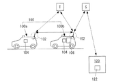
図1は、本発明による遠隔操縦システムの全体構成図である。
この図において、本発明の遠隔操縦システムは、前方車両100aと後方車両100bとからなり遠隔操縦される無人移動体100と、遠隔操縦装置120と、を備える。遠隔操縦装置120は、通信衛星Sを介して後方車両100bを遠隔操縦し、かつ後方車両100bを介して前記前方車両100aを間接的に遠隔操縦する。
後方車両100bは、前方車両100aの後方を所定距離以上離れて走行する。「所定距離」は、前方車両100aが位置補正用の静止衛星Tからの補正信号の受信途絶を検出した際に、後方車両100bが通信衛星Sを介して遠隔操縦装置120との通信を維持できる距離に設定する。
この距離は、例えば後述する水平距離Lであるが、これに限定されず任意に設定することができる。
後方車両100bの走行は、前方車両100aの軌跡を辿る追従であるのが好ましいが、これに限定されず任意に走行することができる。
FIG. 1 is an overall configuration diagram of a remote control system according to the present invention.
In this figure, the remote control system of the present invention includes an unmanned moving
The
This distance is, for example, a horizontal distance L described later, but is not limited thereto and can be set arbitrarily.
The traveling of the
通信衛星Sは、好ましくはJCSAT(登録商標)等の静止衛星である。JCSATとは日本を通信範囲に含む通信衛星である。 The communication satellite S is preferably a geostationary satellite such as JCSAT (registered trademark). JCSAT is a communication satellite that includes Japan in its communication range.
図1において、前方車両100aと後方車両100bは、互いに制御信号を通信する無線通信装置102と、位置補正用の静止衛星Tからの補正信号を受信して自己位置を検出するDGPS受信機104とを有している。
静止衛星Tからの補正信号とは、GPSの誤差補正データ(ディファレンシャル補正)である。
In FIG. 1, a
The correction signal from the geostationary satellite T is GPS error correction data (differential correction).
位置補正用の静止衛星Tは、好ましくはDGPSのSBAS方式であるMTSAT1衛星とMTSAT2衛星である。 The geostationary satellites T for position correction are MTSAT1 satellite and MTSAT2 satellite which are preferably DGPS's SBAS system.
MTSAT1衛星とMTSAT2衛星は、日本が打ち上げた運輸多目的静止衛星であり、グローバル・ポジショニング・システム(GPS)による測位精度を補強するSBAS方式(Satellite Based Augmentation System)を用い、GPSの誤差補正データ(ディファレンシャル補正)を提供している。
GPS(グローバル・ポジショニング・システム)は、米国が運用する衛星航法システムである。GPS受信機は、GPS衛星からの電波を使って、受信機とGPS衛星との間の距離を測定し、位置を計算する。
DGPS(ディファレンシャルGPS)は、MTSAT1衛星とMTSAT2衛星の誤差補正データ(ディファレンシャル補正)を用いて、GPS受信機の精度を高めたシステムである。
The MTSAT1 and MTSAT2 satellites are multipurpose geostationary satellites launched by Japan that use the SBAS method (Satellite Based Augmentation System) to reinforce the positioning accuracy of the global positioning system (GPS), and use GPS error correction data (differential). Amendment).
GPS (Global Positioning System) is a satellite navigation system operated by the United States. The GPS receiver measures the distance between the receiver and the GPS satellite using radio waves from the GPS satellite and calculates the position.
DGPS (differential GPS) is a system in which the accuracy of a GPS receiver is increased by using error correction data (differential correction) of MTSAT1 and MTSAT2 satellites.
後方車両100bは、さらに通信衛星Sを介して遠隔操縦装置120と制御信号を通信する衛星通信装置106を有する。
遠隔操縦装置120は、例えばコンピュータ(PC)であり、無人移動体100を遠隔操縦するための表示装置、キーボード、操舵レバー(ジョイスティック等)を有する。
遠隔操縦装置120は、さらに予測装置122を有する。予測装置122は前方車両100aによる補正信号(MTSAT1衛星とMTSAT2衛星の誤差補正データ)の受信途絶により、後方車両100bと遠隔操縦装置120との通信を維持したまま、後方車両100bによる通信衛星Sとの通信途絶位置Cを予測する。
The
The
The
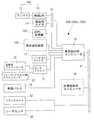
図2は、無人移動体100の構成図であり、図3は、無人移動体100の制御機器のブロック図である。図2、図3において、破線で示すものは、後方車両100bのみが有する。その他は共通である。
以下、初めに前方車両100aと後方車両100bの共通部分を説明する。
FIG. 2 is a configuration diagram of the unmanned
Hereinafter, the common part of the
図2、図3において、上述した無線通信装置102は、アンテナ12と無線LAN13からなり、前方車両100aと後方車両100bの間で互いに制御信号を通信する。なおこの制御信号は、通信衛星Sを介して後方車両100bと遠隔操縦装置120との間でも双方向に通信される。
2 and 3, the
前方車両100aと後方車両100bは、さらに、車両制御用コンピュータ10、操縦用カメラ14、及び入出力回路15を有する。
The
図3において、車両制御用コンピュータ10の入力側には、アンテナ12と接続する無線LAN13及び操縦用カメラ14が入出力回路15を介して接続されている。さらに、位置情報取得用のDGPS受信機104、衛星通信装置106、姿勢制御用のバーチカルジャイロ17、及び移動速度測定用の車速パルス18がシリアル回線を介して車両制御用コンピュータ10の入力側に接続されている。
In FIG. 3, a
図3において、車両制御用コンピュータ10の出力側には、モータドライバ21を介して操舵用アクチュエータ22及びブレーキ/アクセル用アクチュエータ23が接続されており、これらのアクチュエータ22,23と車輪とで駆動ユニット20を構成している。
In FIG. 3, a
車両制御用コンピュータ10は、DGPS受信機104やバーチカルジャイロ17で取得した各種情報をLAN11、無線LAN13及びアンテナ12を介して遠隔操縦装置120に送信する機能を有している。
車両制御用コンピュータ10は、さらに遠隔操縦装置120から送信される操作情報に基づいて、モータドライバ21を介して操舵用アクチュエータ22及びブレーキ/アクセル用アクチュエータ23を作動、停止させる機能を有している。
The
The
図3において、前方車両100aと後方車両100bは、さらに、ステレオカメラ32とレーザセンサ34を有する。
ステレオカメラ32は、遠距離で且つ広角情報取得に適した例えば1対のカメラである。またレーザセンサ34は、近距離情報取得に適した例えばレーザレンジファインダである。ステレオカメラ32とレーザセンサ34は、LAN11を介して車両制御用コンピュータ10に接続されている。
In FIG. 3, the
The
図2、図3において、後方車両100bは、さらに破線で示す自律制御用コンピュータ30を備える。なお、前方車両100aも、自律制御用コンピュータ30を備えることが好ましい。
自律制御用コンピュータ30は、LAN11を介して車両制御用コンピュータ10に接続されている。
2 and 3, the
The
自律制御用コンピュータ30は、ステレオカメラ32とレーザセンサ34により取得した近距離情報及び遠距離情報に基づいて、操舵用アクチュエータ22及びブレーキ/アクセル用アクチュエータ23を作動させて可能な範囲で無人移動体100(前方車両100a又は後方車両100b)を自律走行させる。
The
なお、自律制御用コンピュータ30による自律走行は、少なくとも軌跡追従機能を有する。すなわち、後方車両100bは、軌跡追従機能を有する。
この軌跡追従機能により、後方車両100bは、前方車両100aによる補正信号の受信が再確立された後、通信衛星Sとの通信途絶位置Cから補正信号の受信の再確立位置(図示せず)までの前方車両100aの軌跡を辿って移動する。
Note that autonomous running by the
By this trajectory tracking function, the
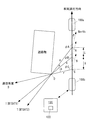
図4は、予測装置122により通信途絶位置Cを予測する方法の説明図であり、2台の無人移動体100が走行する進行方向の平面図を示している。
この図に示すように、前方車両100aが先行し、後方車両100bは前方車両100aから所定距離以上離れて走行する。好ましくは、後方車両100bは、前方車両100aの走行軌跡を辿って追従する。
FIG. 4 is an explanatory diagram of a method of predicting the communication interruption position C by the
As shown in this figure, the
図4において、前方車両100aの進行に伴い、DGPS状態としてMTSAT1衛星、MTSAT2衛星の信号が途絶えた地点(受信途絶位置)をそれぞれ地点B,Aとする。この両点間の水平距離Lと、既知である衛星の経度情報より、衛星通信を行う後方車両100bの衛星通信が途切れる通信途絶位置Cを数1の式(1)〜(5)により求める。
In FIG. 4, points B and A are points where the signals of the MTSAT1 satellite and the MTSAT2 satellite are interrupted as the DGPS state as the

ここでφAは、MTSAT1衛星の経度(真北からの角度)、φBは、MTSAT2衛星の経度(真北からの角度)、φCは、通信衛星(JCSAT等)の経度(真北からの角度)であり、いずれも既知の一定値である。
また、δは、前方車両100aの北方向(真北)に対する進行方位であり、DGPS受信機104からリアルタイムに得られる。
この図において、Oは衛星通信及びMTSAT1衛星、MTSAT2衛星に対する遮蔽点の平面位置である。
Where φA is the longitude of MTSAT1 satellite (angle from true north), φB is the longitude of MTSAT2 satellite (angle from true north), and φC is the longitude of communication satellite (JCSAT etc.) (angle from true north) And both are known constant values.
Further, δ is a traveling direction with respect to the north direction (true north) of the preceding
In this figure, O is the planar position of the shielding point with respect to satellite communication and the MTSAT1 satellite and MTSAT2 satellite.
数1において、aを角度AOB、bを角度BOC、pを点OA間の距離、qを点OB間の距離、rを点OC間の距離、Lを点AB間の水平距離、Xを点BC間の距離とする。
In
正弦定理より、式(1)(2)が得られ、三角形の定理より、式(3)(4)が得られる。
また、式(1)〜(4)から、式(5)が導かれる。
Equations (1) and (2) are obtained from the sine theorem, and equations (3) and (4) are obtained from the triangle theorem.
Moreover, Formula (5) is guide | induced from Formula (1)-(4).
従って、予測装置122により、前方車両100aによるMTSAT1衛星とMTSAT2衛星の受信途絶位置間の水平距離Lと、前方車両100aの進行方位δとから、通信衛星Sとの通信途絶位置Cを算出することができる。
Therefore, the
なお、この図は、2台の無人移動体100が北方向に向かっている場合を示しているが、各点の位置関係は、北方向以外の場合でも同じである。
従って、前方車両100aと後方車両100bの間隔は、北方向に向かう場合は、上記距離L以上離れるのが好ましく、南方向に向かう場合は、距離L以下であってもよい。
実際問題としては、前方車両100aのDGPS状態が途絶える地点A,Bを知るだけでも、衛星通信途絶に備えた制御の準備を始められるため、実運用上のメリットは大きい。
In addition, although this figure has shown the case where the two unmanned
Therefore, the distance between the
As an actual problem, just knowing the points A and B where the DGPS state of the preceding
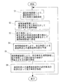
図5は、本発明による遠隔操縦方法を示す全体フロー図である。
この図において、本発明の遠隔操縦方法は、S1〜S6の各ステップからなる。
無人移動体100は、上述したように、前方車両100aとその後方を所定距離以上離れて走行する後方車両100bとからなり、遠隔操縦装置120により遠隔操縦される。
遠隔操縦装置120は、通信衛星Sを介して後方車両100bを遠隔操縦し、かつ後方車両100bを介して前記前方車両100aを間接的に遠隔操縦する。
FIG. 5 is an overall flowchart showing a remote control method according to the present invention.
In this figure, the remote control method of the present invention comprises steps S1 to S6.
As described above, the unmanned
The
後方車両100bは、通信衛星Sを介して遠隔操縦装置120と制御信号を通信する衛星通信装置106を有しており、ステップS1において、遠隔操縦装置120により、通信衛星Sを介して後方車両100bを遠隔操縦する。
また、前方車両100aと後方車両100bは、互いに制御信号を通信する無線通信装置102を有しており、ステップS2において、遠隔操縦装置120により、通信衛星Sと無線通信装置102を介して前方車両100aを遠隔操縦する。
なお、ステップS1とステップS2の順序は逆でもよく、同時であってもよい。
The
Further, the
In addition, the order of step S1 and step S2 may be reverse, and may be simultaneous.
また、前方車両100aは、位置補正用の静止衛星Tからの補正信号を受信して自己位置を検出するDGPS受信機104を有しており、ステップS3において、前方車両100aは、補正信号の受信途絶位置A,Bを検出し、通信衛星Sと無線通信装置102を介して遠隔操縦装置120に通信する。
ステップS3における位置補正用の静止衛星Tは、DGPSのSBAS方式であるMTSAT1衛星とMTSAT2衛星である。従って、補正信号の受信途絶位置は、上述したA点とB点である。
The
The geostationary satellites T for position correction in step S3 are the MTSAT1 satellite and the MTSAT2 satellite, which are DGPS SBAS systems. Therefore, the reception interruption positions of the correction signal are the points A and B described above.
遠隔操縦装置120は、ステップS4において、前方車両100aによる補正信号の受信途絶により、後方車両100bと遠隔操縦装置120との通信を維持したまま、後方車両100bによる通信衛星Sとの通信途絶位置Cを予測する。
すなわち、ステップS4において、前方車両100aによるMTSAT1衛星とMTSAT2衛星の受信途絶位置A,Bの距離Lと、前方車両100aの進行方位δとから、上述した式(5)により、通信衛星Sとの通信途絶位置Cを算出する。
In step S4, the
That is, in step S4, from the distance L between the reception interruption positions A and B of the MTSAT1 satellite and the MTSAT2 satellite by the
ステップS5において、遠隔操縦装置120は、通信衛星Sと無線通信装置102を介して前方車両100aを遠隔操縦し、前方車両100aによる補正信号の受信が再確立される位置を探索する。
この探索は、通信衛星Sと無線通信装置102を介する遠隔操縦が可能な範囲で、元のコースを戻ってもよく、或いはそのまま前進してもよい。
In step S5, the
This search may return to the original course or proceed as it is within a range where remote control via the communication satellite S and the
前方車両100aがそのまま前進し、補正信号の受信が再確立される位置を検出した場合には、ステップS6において、通信衛星Sとの通信途絶箇所(通信途絶位置から補正信号の受信の再確立位置まで)の前方車両100aの軌跡を辿って後方車両100bを移動させる。この際、後方車両100bが有する軌跡追従機能を用いる。
なお、後方車両100bの軌跡追従機能は、必須ではなく、これを用いずに、通信途絶箇所を回避してもよい。
以下、ステップS1に戻り、S1〜S6の各ステップを繰り返して走行する。
When the
In addition, the locus | trajectory tracking function of the
Thereafter, the process returns to step S1 and travels by repeating steps S1 to S6.
上述した本発明の装置と方法によれば、後方車両100bが、通信衛星Sを介して遠隔操縦装置120と制御信号を通信する衛星通信装置106を有しているので、遠隔操縦装置120により、通信衛星Sを介して後方車両100bを遠隔操縦することができる。
また、前方車両100aと後方車両100bは、互いに制御信号を通信する無線通信装置102を有しているので、遠隔操縦装置120により、通信衛星Sと無線通信装置102を介して前方車両100aを遠隔操縦することができる。
従って、衛星通信装置106を全車両に搭載する必要がなく、かつ遠隔操縦装置120により、自律走行ができない2台の無人移動体100(前方車両100aと後方車両100b)の遠隔操縦が可能である。
According to the apparatus and method of the present invention described above, the
Further, since the
Therefore, it is not necessary to mount the
また、前方車両100aは、位置補正用の静止衛星Tからの補正信号を受信して自己位置を検出するDGPS受信機104を有しているので、この補正信号の受信途絶を検出し、無線通信装置102を介して後方車両100bに補正信号の受信途絶を通信することができる。
また、前方車両100aが補正信号の受信途絶を検出しても、後方車両100bは、前方車両100aの後方を所定距離以上離れて走行するので、補正用の静止衛星Tからの補正信号を受信して自己位置を精度よく検出することができる。
Further, the
Further, even if the preceding
さらに、前方車両100aによる補正信号の受信途絶の位置において、後方車両100bと遠隔操縦装置120との通信衛星Sによる通信は維持されているので、遠隔操縦装置120は、後方車両100bと遠隔操縦装置120との通信を維持したまま、通信衛星Sとの通信途絶位置Cを予測することができる。
Further, since the communication by the communication satellite S between the
従って、通信衛星を介した衛星通信ができるかぎり、対象物までの距離、天候、昼夜等の影響を受けることなく、通信途絶箇所を予測し、前方車両100aと後方車両100bを遠隔制御してこの箇所を回避又は通過させることができる。
Therefore, as long as satellite communication through the communication satellite is possible, the communication interruption point is predicted without being affected by the distance to the object, the weather, day and night, and the
なお本発明は上述した実施の形態に限定されず、本発明の要旨を逸脱しない範囲で種々変更を加え得ることは勿論である。 Note that the present invention is not limited to the above-described embodiment, and it is needless to say that various modifications can be made without departing from the gist of the present invention.
A MTSAT2衛星の信号が途絶えた地点(受信途絶位置)、
B MTSAT1衛星の信号が途絶えた地点(受信途絶位置)、
C 後方車両の衛星通信が途切れる地点(通信途絶位置)、
S 通信衛星、T 位置補正用の静止衛星、
φA MTSAT1衛星の経度、φB MTSAT2衛星の経度、
φC 通信衛星の経度、δ 前方車両の北に対する進行方位、
O 衛星通信及びMTSAT1衛星、MTSAT2衛星に対する遮蔽点の平面位置、
a 角度AOB、b 角度BOC、p 点OA間の距離、
q 点OB間の距離、r 点OC間の距離、L 点AB間の水平距離、
X 点BC間の距離、10 車両制御用コンピュータ、11 LAN、
12 アンテナ、13 無線LAN、14 操縦用カメラ、
15 入出力回路、17 バーチカルジャイロ、18 車速パルス、
20 駆動ユニット、21 モータドライバ、
22 操舵用アクチュエータ、
23 ブレーキ/アクセル用アクチュエータ、
30 自律制御用コンピュータ、32 ステレオカメラ、
34 レーザセンサ、100 無人移動体、100a 前方車両、
100b 後方車両、102 無線通信装置、104 DGPS受信機、
106 衛星通信装置、120 遠隔操縦装置、122 予測装置
A Point where the signal of the MTSAT2 satellite was interrupted (reception interruption position),
B Point where the signal of the MTSAT1 satellite was interrupted (reception interruption position),
C Point where satellite communication of rear vehicle is interrupted (communication interruption position),
S communication satellite, T geostationary satellite for position correction,
The longitude of φA MTSAT1 satellite, the longitude of φB MTSAT2 satellite,
φC Longitude of communication satellite, δ Heading direction of vehicle ahead,
O Planar position of shielding point for satellite communication and MTSAT1 satellite, MTSAT2 satellite,
a angle AOB, b angle BOC, distance between point OA,
q Distance between point OB, distance between r point OC, horizontal distance between L point AB,
X Distance between points BC, 10 Vehicle control computer, 11 LAN,
12 antenna, 13 wireless LAN, 14 steering camera,
15 input / output circuit, 17 vertical gyro, 18 vehicle speed pulse,
20 drive unit, 21 motor driver,
22 Steering actuator,
23 Brake / accelerator actuators,
30 computers for autonomous control, 32 stereo cameras,
34 laser sensor, 100 unmanned moving body, 100a vehicle ahead,
100b Rear vehicle, 102 wireless communication device, 104 DGPS receiver,
106 Satellite communication device, 120 Remote control device, 122 Prediction device
Claims (6)
通信衛星を介して前記後方車両を遠隔操縦し、かつ後方車両を介して前記前方車両を間接的に遠隔操縦する遠隔操縦装置と、を備え、
前記前方車両と前記後方車両は、互いに制御信号を通信する無線通信装置と、位置補正用の静止衛星からの補正信号を受信して自己位置を検出するDGPS受信機とを有しており、
前記後方車両は、さらに前記通信衛星を介して前記遠隔操縦装置と前記制御信号を通信する衛星通信装置を有し、
前記遠隔操縦装置は、前記前方車両による前記補正信号の受信途絶により、後方車両と遠隔操縦装置との通信を維持したまま、前記後方車両による前記通信衛星との通信途絶位置を予測する予測装置を有する、ことを特徴とする遠隔操縦システム。 An unmanned moving body that is remotely operated and includes a front vehicle and a rear vehicle that travels a predetermined distance or more behind the front vehicle;
A remote control device for remotely maneuvering the rear vehicle via a communication satellite and indirectly remotely maneuvering the front vehicle via the rear vehicle;
The front vehicle and the rear vehicle have a wireless communication device that communicates a control signal with each other, and a DGPS receiver that receives a correction signal from a position correction geostationary satellite and detects its own position,
The rear vehicle further includes a satellite communication device that communicates the control signal with the remote control device via the communication satellite,
The remote control device is a prediction device that predicts a communication interruption position with the communication satellite by the rear vehicle while maintaining communication between the rear vehicle and the remote control device due to the reception interruption of the correction signal by the front vehicle. A remote control system characterized by comprising:
前記予測装置は、前記前方車両による前記MTSAT1衛星と前記MTSAT2衛星の受信途絶位置間の水平距離と、前記前方車両の進行方位とから、前記通信衛星との通信途絶位置を算出する、ことを特徴とする請求項1に記載の遠隔操縦システム。 The geostationary satellites for position correction are MTSAT1 satellite and MTSAT2 satellite which are DGPS SBAS systems,
The prediction device calculates a communication interruption position with the communication satellite from a horizontal distance between the reception interruption positions of the MTSAT1 satellite and the MTSAT2 satellite by the front vehicle and a traveling direction of the front vehicle. The remote control system according to claim 1.
通信衛星を介して前記後方車両を遠隔操縦し、かつ後方車両を介して前記前方車両を間接的に遠隔操縦する遠隔操縦装置と、を準備し、
前記前方車両と前記後方車両は、互いに制御信号を通信する無線通信装置と、位置補正用の静止衛星からの補正信号を受信して自己位置を検出するDGPS受信機とを有しており、
前記後方車両は、さらに前記通信衛星を介して前記遠隔操縦装置と前記制御信号を通信する衛星通信装置を有し、
前記遠隔操縦装置により、前記前方車両による前記補正信号の受信途絶により、後方車両と遠隔操縦装置との通信を維持したまま、前記後方車両による前記通信衛星との通信途絶位置を予測する、ことを特徴とする遠隔操縦方法。 An unmanned moving body that is remotely operated and includes a front vehicle and a rear vehicle that travels a predetermined distance or more behind the front vehicle;
A remote control device for remotely maneuvering the rear vehicle via a communication satellite and indirectly remotely maneuvering the front vehicle via the rear vehicle;
The front vehicle and the rear vehicle have a wireless communication device that communicates a control signal with each other, and a DGPS receiver that receives a correction signal from a position correction geostationary satellite and detects its own position,
The rear vehicle further includes a satellite communication device that communicates the control signal with the remote control device via the communication satellite,
The remote control device predicts a communication interruption position with the communication satellite by the rear vehicle while maintaining communication between the rear vehicle and the remote control device due to the reception interruption of the correction signal by the front vehicle. A remote control method characterized.
前記前方車両による前記MTSAT1衛星と前記MTSAT2衛星の受信途絶位置間の水平距離と、前記前方車両の進行方位とから、前記通信衛星との通信途絶位置を算出する、ことを特徴とする請求項4に記載の遠隔操縦方法。 The geostationary satellites for position correction are MTSAT1 satellite and MTSAT2 satellite which are DGPS SBAS systems,
5. The communication interruption position with the communication satellite is calculated from a horizontal distance between reception interruption positions of the MTSAT1 satellite and the MTSAT2 satellite by the front vehicle and a traveling direction of the front vehicle. The remote control method described in 1.
前記前方車両による前記補正信号の受信が再確立された後、前記通信衛星との通信途絶位置から前記補正信号の受信の再確立位置までの前方車両の軌跡を辿って後方車両を移動させる、ことを特徴とする請求項4に記載の遠隔操縦方法。
Remotely steer forward vehicles through communication satellites and wireless communication devices,
After the reception of the correction signal by the preceding vehicle is re-established, the vehicle behind the vehicle is moved by following the trajectory of the preceding vehicle from the communication interruption position with the communication satellite to the re-establishment position of the reception of the correction signal. The remote control method according to claim 4.
Priority Applications (1)
| Application Number | Priority Date | Filing Date | Title |
|---|---|---|---|
| JP2014209110A JP6366182B2 (en) | 2014-10-10 | 2014-10-10 | Remote control system and remote control method |
Applications Claiming Priority (1)
| Application Number | Priority Date | Filing Date | Title |
|---|---|---|---|
| JP2014209110A JP6366182B2 (en) | 2014-10-10 | 2014-10-10 | Remote control system and remote control method |
Publications (2)
| Publication Number | Publication Date |
|---|---|
| JP2016081122A JP2016081122A (en) | 2016-05-16 |
| JP6366182B2 true JP6366182B2 (en) | 2018-08-01 |
Family
ID=55958732
Family Applications (1)
| Application Number | Title | Priority Date | Filing Date |
|---|---|---|---|
| JP2014209110A Active JP6366182B2 (en) | 2014-10-10 | 2014-10-10 | Remote control system and remote control method |
Country Status (1)
| Country | Link |
|---|---|
| JP (1) | JP6366182B2 (en) |
Families Citing this family (4)
| Publication number | Priority date | Publication date | Assignee | Title |
|---|---|---|---|---|
| KR102112825B1 (en) * | 2017-12-26 | 2020-05-19 | 한국항공우주연구원 | Realtime GNSS Data Correction System, Method and Computer Readable Recording Mediuim |
| SE543068C2 (en) * | 2018-11-09 | 2020-09-29 | Scania Cv Ab | Minimizing perceived communication downtime for a group of vehicles |
| JP7111022B2 (en) * | 2019-02-18 | 2022-08-02 | トヨタ自動車株式会社 | Control device |
| JPWO2022014174A1 (en) * | 2020-07-15 | 2022-01-20 |
Family Cites Families (5)
| Publication number | Priority date | Publication date | Assignee | Title |
|---|---|---|---|---|
| JPH0884375A (en) * | 1994-09-09 | 1996-03-26 | Shin Caterpillar Mitsubishi Ltd | Remote controller for unattended construction machine |
| JP3262967B2 (en) * | 1995-05-24 | 2002-03-04 | 三菱電機株式会社 | Satellite navigation equipment |
| JP2001334893A (en) * | 2000-03-22 | 2001-12-04 | Hitoshi Ishida | Remote operation system for vehicle |
| JP2004312376A (en) * | 2003-04-07 | 2004-11-04 | Toyota Motor Corp | Equipment control system and equipment control method |
| JP2007201867A (en) * | 2006-01-27 | 2007-08-09 | Mitsubishi Electric Corp | Data communication system and method, and ground station |
-
2014
- 2014-10-10 JP JP2014209110A patent/JP6366182B2/en active Active
Also Published As
| Publication number | Publication date |
|---|---|
| JP2016081122A (en) | 2016-05-16 |
Similar Documents
| Publication | Publication Date | Title |
|---|---|---|
| US10796204B2 (en) | Planning system and method for controlling operation of an autonomous vehicle to navigate a planned path | |
| CN108973992B (en) | Travel control device, travel control method, and storage medium | |
| CN109891470B (en) | Remote operation system, traffic system and remote operation method | |
| US10459087B2 (en) | Road registration differential GPS | |
| KR102508275B1 (en) | Travel route specification system | |
| JP2019532292A (en) | Autonomous vehicle with vehicle location | |
| JP6366182B2 (en) | Remote control system and remote control method | |
| JPWO2018122973A1 (en) | Vehicle control system, vehicle control method, and vehicle control program | |
| US20190250001A1 (en) | Vehicle control system, vehicle control method, and vehicle storage medium | |
| EP3470947B1 (en) | Method and system for guiding an autonomous vehicle | |
| JP6982999B2 (en) | Route determination device and route determination method | |
| US11755019B2 (en) | Vehicle control device and vehicle control system | |
| JP6614509B2 (en) | Vehicle control device, vehicle control method, and program | |
| EP3674177B1 (en) | Onboard processing device and control method for onboard processing device | |
| KR20160038319A (en) | Method for displaying location of vehicle | |
| JP2019067295A (en) | Vehicle control device, vehicle control method, and program | |
| Bao et al. | Outdoor navigation of a mobile robot by following GPS waypoints and local pedestrian lane | |
| Suganuma et al. | Development of an autonomous vehicle—System overview of test ride vehicle in the Tokyo motor show 2011 | |
| JP6323016B2 (en) | Control center and automatic driving system | |
| US11760379B2 (en) | Navigating an autonomous vehicle through an intersection | |
| CN114954511A (en) | Vehicle control device, vehicle control method, and storage medium | |
| CN114281109A (en) | Multi-machine cooperation control system guided by unmanned aerial vehicle | |
| CN115143957A (en) | Detection device, vehicle system, detection method, and storage medium | |
| US8942863B2 (en) | Worksite position control system having integrity checking | |
| JP2018002143A (en) | Travel device, travel control system, travel control method and program |
Legal Events
| Date | Code | Title | Description |
|---|---|---|---|
| A621 | Written request for application examination |
Free format text: JAPANESE INTERMEDIATE CODE: A621 Effective date: 20170824 |
|
| A977 | Report on retrieval |
Free format text: JAPANESE INTERMEDIATE CODE: A971007 Effective date: 20180608 |
|
| TRDD | Decision of grant or rejection written | ||
| A01 | Written decision to grant a patent or to grant a registration (utility model) |
Free format text: JAPANESE INTERMEDIATE CODE: A01 Effective date: 20180622 |
|
| A61 | First payment of annual fees (during grant procedure) |
Free format text: JAPANESE INTERMEDIATE CODE: A61 Effective date: 20180702 |
|
| R150 | Certificate of patent or registration of utility model |
Ref document number: 6366182 Country of ref document: JP Free format text: JAPANESE INTERMEDIATE CODE: R150 |
|
| R250 | Receipt of annual fees |
Free format text: JAPANESE INTERMEDIATE CODE: R250 |
|
| R250 | Receipt of annual fees |
Free format text: JAPANESE INTERMEDIATE CODE: R250 |
|
| R250 | Receipt of annual fees |
Free format text: JAPANESE INTERMEDIATE CODE: R250 |