JP6358816B2 - Medical image diagnostic apparatus and image processing method used therefor - Google Patents
Medical image diagnostic apparatus and image processing method used therefor Download PDFInfo
- Publication number
- JP6358816B2 JP6358816B2 JP2014042041A JP2014042041A JP6358816B2 JP 6358816 B2 JP6358816 B2 JP 6358816B2 JP 2014042041 A JP2014042041 A JP 2014042041A JP 2014042041 A JP2014042041 A JP 2014042041A JP 6358816 B2 JP6358816 B2 JP 6358816B2
- Authority
- JP
- Japan
- Prior art keywords
- image
- coordinates
- calculated
- processing method
- diagnostic apparatus
- Prior art date
- Legal status (The legal status is an assumption and is not a legal conclusion. Google has not performed a legal analysis and makes no representation as to the accuracy of the status listed.)
- Active
Links
- 238000003672 processing method Methods 0.000 title claims description 16
- 238000003384 imaging method Methods 0.000 claims description 60
- 239000013598 vector Substances 0.000 claims description 29
- 238000012545 processing Methods 0.000 claims description 17
- 238000005259 measurement Methods 0.000 claims description 3
- 238000002059 diagnostic imaging Methods 0.000 claims 1
- 238000002595 magnetic resonance imaging Methods 0.000 description 27
- 238000005481 NMR spectroscopy Methods 0.000 description 7
- 238000010586 diagram Methods 0.000 description 6
- 238000012937 correction Methods 0.000 description 4
- 230000003068 static effect Effects 0.000 description 4
- 241001465754 Metazoa Species 0.000 description 3
- 238000004458 analytical method Methods 0.000 description 3
- 238000007796 conventional method Methods 0.000 description 3
- 238000000034 method Methods 0.000 description 3
- 238000004891 communication Methods 0.000 description 2
- 238000001208 nuclear magnetic resonance pulse sequence Methods 0.000 description 2
- 210000001015 abdomen Anatomy 0.000 description 1
- 210000003484 anatomy Anatomy 0.000 description 1
- 230000005540 biological transmission Effects 0.000 description 1
- 238000004364 calculation method Methods 0.000 description 1
- 238000006243 chemical reaction Methods 0.000 description 1
- 229940079593 drug Drugs 0.000 description 1
- 239000003814 drug Substances 0.000 description 1
- 238000007689 inspection Methods 0.000 description 1
- 238000012986 modification Methods 0.000 description 1
- 230000004048 modification Effects 0.000 description 1
Images


Description
本発明は、医用画像診断装置に係り、特に、この装置にて取得した画像の位置情報を設定する方法に関する。 The present invention relates to a medical image diagnostic apparatus, and more particularly to a method for setting position information of an image acquired by this apparatus.
医用画像診断装置の一つとしてMRI(Magnetic Resonance Imaging)装置がある。MRI装置は、磁場中に置かれた被検体の核磁気共鳴(以下「NMR(Nuclear Magnetic Resonance)」という)現象から得られる信号を計測し演算処理することにより、被検体中の核スピンの密度分布、緩和時間分布等を断層像として画像表示するものであり、人体や動物を被検体として各種の診断等に使用されている。NMR現象から信号を得るためには、空間的、時間的に一様な静磁場中に被検体を置き、高周波コイルによりパルス状に電磁波を被検体に照射し、それによって発生するNMR信号を高周波コイルにより受信する。さらにNMR信号に位置情報を与えるために静磁場に傾斜磁場が重畳される。これにより、任意断面の撮像を実現している。 As one of medical image diagnostic apparatuses, there is an MRI (Magnetic Resonance Imaging) apparatus. The MRI system measures and computes the signal obtained from the nuclear magnetic resonance (hereinafter referred to as “NMR (Nuclear Magnetic Resonance)”) phenomenon of a subject placed in a magnetic field, thereby calculating the density of nuclear spins in the subject. Distribution, relaxation time distribution, and the like are displayed as tomographic images, and are used for various diagnoses and the like with a human body or animal as a subject. In order to obtain a signal from the NMR phenomenon, the subject is placed in a spatially and temporally uniform static magnetic field, and the subject is irradiated with electromagnetic waves in a pulsed manner by a high-frequency coil. Receive by coil. Further, a gradient magnetic field is superimposed on the static magnetic field in order to give position information to the NMR signal. Thereby, imaging of an arbitrary cross section is realized.
MRI装置において、被検体の撮像対象部位の断層像撮像前に、撮像予定面を決定するために用いる位置決め用画像を取得する。取得した位置決め用画像が持つ解剖学的特徴を元に所望の断層像の撮像予定面を自動で算出することができる従来技術として、WO2013/027540号公報(特許文献1)がある。(以下、この従来技術を自動位置決めという)なお、医用画像では、その画像の三次元的な位置を示す座標と画像の向きを持つ。これらの座標軸は、被検体の体の向きに沿って規定されている。 In the MRI apparatus, a positioning image used for determining a planned imaging plane is acquired before tomographic imaging of the imaging target region of the subject. There is WO2013 / 0275540 (Patent Document 1) as a prior art that can automatically calculate the imaging plane of a desired tomographic image based on the anatomical characteristics of the acquired positioning image. Note that a medical image has coordinates indicating the three-dimensional position of the image and the orientation of the image. These coordinate axes are defined along the direction of the body of the subject.
また、画像の位置を示す座標と画像の向きの情報を元に、画像内の被検体の向きが判定され、それを表示する従来技術として、生成された画像と体位情報がずれている場合の補正を行う、特開2006−246937号公報(特許文献2)がある。 Also, based on the coordinates indicating the position of the image and the information on the orientation of the image, the orientation of the subject in the image is determined, and as a conventional technique for displaying it, the generated image and the posture information are shifted. There exists Unexamined-Japanese-Patent No. 2006-246937 (patent document 2) which correct | amends.
上記特許文献1の課題について図2に基づいて説明する。 The subject of the said patent document 1 is demonstrated based on FIG.
図2において、画像の三次元的な位置を示す座標と画像の向きを示す単位ベクトルは、被検者の体の向きに沿って規定された座標軸(201,202)に従って表される。従来のMRI装置では、被検体のMRI装置に対する向きを操作者が撮像前に設定する必要があるが、被検体の向きをMRI装置に対して直交する方向にしか選択できず、被検体がMRI装置に対して斜めの方向(203)に向いている場合、自動位置決めで撮像する領域(204)は変わるが、座標軸(201,202)は変わらない。このため、取得される画像(206)の位置を示す座標(207)と、画像(206)の向きを示すベクトル(208,209)の座標軸は被検体に対して斜めを向いた状態になり、例えば被検体にとっての右方向(210)が座標上では右後ろの方向となってしまう。また、座標軸の原点の位置と被検体との関係は検査ごとに異なる関係となってしまうという問題があった。 In FIG. 2, the coordinates indicating the three-dimensional position of the image and the unit vector indicating the orientation of the image are represented according to coordinate axes (201, 202) defined along the direction of the body of the subject. In the conventional MRI apparatus, the operator needs to set the orientation of the subject with respect to the MRI apparatus before imaging. However, the orientation of the subject can be selected only in the direction orthogonal to the MRI apparatus, and the subject can be selected as the MRI apparatus. When facing in an oblique direction (203) with respect to the apparatus, the area (204) for imaging by automatic positioning changes, but the coordinate axes (201, 202) do not change. For this reason, the coordinates (207) indicating the position of the acquired image (206) and the coordinate axes of the vectors (208, 209) indicating the orientation of the image (206) are in an oblique direction with respect to the subject. For example, the right direction (210) for the subject is the right rear direction on the coordinates. In addition, there is a problem that the relationship between the position of the origin of the coordinate axis and the subject is different for each examination.
また、特許文献2では、生成された画像を補正した状態で表示するには、この補正機能を備えた装置で表示する必要があり、この補正機能を備えていない装置では対応できないという問題がある。また、補正表示するための体位情報は、画像の上下左右の方向が被検体の上、下、右、左、前、後のどれに対応するかを示すのみであり、45度刻みの補正しか行えず、大まかな補正しか行えないという問題があった。 Further, in Patent Document 2, in order to display the generated image in a corrected state, it is necessary to display the image with a device having this correction function, and there is a problem that a device without this correction function cannot cope with it. . The body position information for correction display only indicates whether the top / bottom / left / right direction of the image corresponds to the top, bottom, right, left, front, or back of the subject. There was a problem that only rough correction could be performed.
よって、本発明の目的は、操作者が撮像前に被検体の向きを指定することなく、被検体ごとの同じ座標軸に対して、取得した画像の座標と画像の向きを示すベクトルとが設定される医用画像診断装置を提供することにある。 Therefore, the object of the present invention is to set the coordinates of the acquired image and the vector indicating the image orientation for the same coordinate axis for each subject without the operator specifying the orientation of the subject before imaging. It is to provide a medical image diagnostic apparatus.
上記課題を解決するために、例えば特許請求の範囲に記載の構成を採用する。本願は上記課題を解決する手段を複数含んでいるが、その一例を挙げるならば、医用画像診断装置で取得した画像の位置情報を設定する画像処理方法であって、撮像した位置決め画像が持つ解剖学的特徴を元に前記医用画像診断装置固有の座標軸に基づく撮像予定面の位置を示す座標と方向を判定し、該判定された座標と方向から新たな座標軸を算出し、該算出した新たな座標軸に基づき、撮像した本撮像画像の位置を示す座標と向きを示すベクトルを算出する構成とする。 In order to solve the above problems, for example, the configuration described in the claims is adopted. The present application includes a plurality of means for solving the above-mentioned problem. To give an example, an image processing method for setting position information of an image acquired by a medical image diagnostic apparatus, which is an anatomy of a captured positioning image. Determining a coordinate and a direction indicating the position of the planned imaging surface based on a coordinate axis unique to the medical image diagnostic apparatus based on a physical feature, calculating a new coordinate axis from the determined coordinate and direction, and calculating the calculated new Based on the coordinate axes, a coordinate indicating the position of the captured main image and a vector indicating the direction are calculated.
本発明によれば、操作者が撮像前に被検体の向きを指定することなく、被検体ごとの同じ座標軸に対して、取得した画像の座標と画像の向きを示すベクトルとが設定される医用画像診断装置を提供することができる。 According to the present invention, the medical image in which the coordinates of the acquired image and the vector indicating the image orientation are set with respect to the same coordinate axis for each subject without the operator specifying the orientation of the subject before imaging. An image diagnostic apparatus can be provided.
以下、本発明の実施例について、図面を用いて詳細に説明する。 Hereinafter, embodiments of the present invention will be described in detail with reference to the drawings.
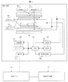
本実施例に係る医用画像診断装置の一例として、MRI装置を用いて以下説明する。MRI装置は、NMR現象を利用して被検体中の所望の検査部位における原子核スピンの密度分布や緩和時間分布等を計測して、その計測から被検体の任意の断面を画像表示するものである。図1にその模式図を示す。 As an example of the medical image diagnostic apparatus according to the present embodiment, an MRI apparatus will be described below. The MRI apparatus measures the density distribution and relaxation time distribution of nuclear spins at a desired examination site in a subject using the NMR phenomenon, and displays an arbitrary cross section of the subject based on the measurement. . FIG. 1 shows a schematic diagram thereof.
図1において、被検体に静磁場を与える静磁場コイル(101)と、被検体に傾斜磁場を与える傾斜磁場コイル(102)と傾斜磁場電源(103)と、被検体の生態組織を構成する原子の原子核にNMR現象を起こさせる高周波パルス(以下RFパルスという)を所定のパルスシーケンスで繰り返し印加する照射コイル(104)と、この照射コイルからのRFパルスにより被検体にRF磁場を照射する送信系(105)と、NMR現象により放出されるエコー信号を検出する受信コイル(106)と受信系(107)と、この受信系で検出したエコー信号を用いて画像再構成演算を行う信号処理およびフィルムへ出力を行う処理系(CPU)(108)と、画像を表示する表示手段(ディスプレイ)(109)と、これらを制御するための操作卓(110)と、データを蓄積する記憶装置(111)を備えている。傾斜磁場は、エコー信号に位置情報を与えるために与えられるもので、直行する3軸方向の傾斜磁場がそれぞれ所定のパルスシーケンスにより印加される。これらのMRI装置により、被検体(112)の任意断面画像を得る。すなわち、被検体から得られる信号を、受信コイル(106)や受信系(107)からなる計測部で計測し、該計測部からの信号を演算処理し、処理系(CPU)(108)からなる信号処理部で処理することで画像データを構成する。 In FIG. 1, a static magnetic field coil (101) for applying a static magnetic field to a subject, a gradient magnetic field coil (102) for applying a gradient magnetic field to a subject, a gradient magnetic field power source (103), and atoms constituting the biological tissue of the subject. An irradiation coil (104) that repeatedly applies a high-frequency pulse (hereinafter referred to as an RF pulse) that causes an NMR phenomenon to the nucleus of the laser in a predetermined pulse sequence, and a transmission system that irradiates the subject with an RF magnetic field by the RF pulse from the irradiation coil (105), a receiving coil (106) and a receiving system (107) for detecting an echo signal emitted by an NMR phenomenon, and a signal processing and film for performing image reconstruction calculation using the echo signal detected by the receiving system A processing system (CPU) (108) for outputting to the display, display means (display) (109) for displaying an image, and for controlling these Console (110), a storage device for storing data (111). The gradient magnetic field is provided to give positional information to the echo signal, and orthogonal three-axis gradient magnetic fields are respectively applied by a predetermined pulse sequence. An arbitrary cross-sectional image of the subject (112) is obtained by these MRI apparatuses. That is, a signal obtained from the subject is measured by a measuring unit including a receiving coil (106) and a receiving system (107), and a signal from the measuring unit is arithmetically processed to include a processing system (CPU) (108). Image data is configured by processing in the signal processing unit.
取得された被検体の任意断面の画像データは、図示していない出力端子からDICOM形式(詳細は後で説明する)で、ネットワークケーブルや、可搬媒体などを介して、MRI装置の外部の画像サーバ(113)に送られる。さらに画像サーバから外部のディスプレイを備えた画像表示装置(114)に送られ、画像が表示される。 The acquired image data of an arbitrary cross section of the subject is an image outside the MRI apparatus in a DICOM format (details will be described later) from an output terminal (not shown) via a network cable or a portable medium. Sent to the server (113). Further, the image is sent from the image server to an image display device (114) having an external display, and an image is displayed.
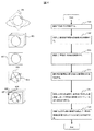
次に本実施例に係る処理概要を図3に基づいて説明する。図3は、右側に本実施例の処理フローチャートを、左側にその説明図を示している。 Next, an outline of processing according to the present embodiment will be described with reference to FIG. FIG. 3 shows a processing flowchart of the present embodiment on the right side and an explanatory diagram on the left side.
図3において、例えば被検体の頭部の撮像を行う場合、まず、S31において、被検体(300)の所望の撮像予定面を決定するために用いる位置決め画像(301)(302)(303)を取得する。例えば、位置決め画像(302)は、図3の左側図304の撮像位置を撮像したものである。 In FIG. 3, for example, when imaging the head of a subject, first, in S31, positioning images (301), (302), and (303) used for determining a desired planned imaging plane of the subject (300) are displayed. get. For example, the positioning image (302) is an image of the imaging position shown in the left diagram 304 of FIG.
次に、S32において、取得した位置決め画像が持つ解剖学的特徴を元に、所望の断層像の撮像予定面を自動で算出する特許文献1記載の従来技術などにより、MRI装置固有の座標軸に基づく三次元的な撮像予定面(305)を決定する。そして、S33において、三次元的な撮像位置(305)の座標と方向から、左図に示すような、その被検体で好適な座標軸(306)と原点(309)の位置を算出する。これらの座標軸と原点は、位置決め画像を撮像した際の原点(307)と座標軸(308)とは異なる。そして、S34において、左図に示すように、位置決め画像(302)の撮像位置(304)の座標軸(306)における画像の位置を示す座標(310)と画像の向きを示すベクトル(311,312)を算出し、位置決め画像(302)の座標と画像方向として保存する。 Next, in S32, based on the anatomical features of the acquired positioning image, based on the coordinate axes unique to the MRI apparatus, such as the conventional technique described in Patent Document 1 that automatically calculates the imaging plane of a desired tomographic image. A three-dimensional imaging scheduled surface (305) is determined. In S33, from the coordinates and direction of the three-dimensional imaging position (305), the positions of the coordinate axes (306) and the origin (309) suitable for the subject as shown in the left figure are calculated. These coordinate axes and the origin are different from the origin (307) and the coordinate axis (308) when the positioning image is captured. In S34, as shown in the left figure, coordinates (310) indicating the position of the image on the coordinate axis (306) of the imaging position (304) of the positioning image (302) and vectors (311 and 312) indicating the orientation of the image. Is calculated and stored as the coordinates and image direction of the positioning image (302).
引き続いて、S35において、本撮像予定面(305)で関心領域の本撮像を行い、本撮像の画像(313)を取得する。最後に、S36において、左図に示すように、変更した座標軸(306)に対する本撮像の画像の位置を示す座標(314)と画像の向きを示すベクトル(315,316)を算出する。この画像の座標(314)とベクトル(315,316)を本撮像の画像(313)の座標と画像方向として保存し、その後の装置上での表示や、外部へ出力する画像データの位置情報として用いる。 Subsequently, in S35, a main imaging of the region of interest is performed on the main imaging scheduled plane (305), and an image (313) of the main imaging is acquired. Finally, in S36, as shown in the left figure, coordinates (314) indicating the position of the image of the main imaging with respect to the changed coordinate axis (306) and vectors (315, 316) indicating the orientation of the image are calculated. The coordinates (314) and vectors (315, 316) of the image are stored as the coordinates and the image direction of the image (313) of the main image pickup, and then displayed on the apparatus or as position information of image data output to the outside. Use.
すなわち、本実施例は、まず撮像予定面を決定するために用いる位置決め用画像を取得する。次に取得した位置決め用画像が持つ解剖学的特徴を元に所望の断層像の撮像予定面を自動で算出する従来技術により、MRI装置固有の座標軸に基づく三次元的な撮像予定面を決定する。この三次元的な撮像予定面を基に被検体の方向を特定し、撮像予定面の座標と向きに即して画像の座標を示す際に使用する座標軸を算出する。MRI装置固有の座標軸と、撮像予定面に合わせた新しい座標軸の原点の位置の移動量と回転角を基に、MRI装置で取得された画像の座標と画像の向きを示すベクトルの情報に変換する。変換された座標と画像の向きのベクトルは、画像の位置情報として、MRI装置上での表示や、MRI装置の外部に出力した先での表示に用いられる。 That is, in this embodiment, first, a positioning image used for determining the imaging scheduled surface is acquired. Next, based on the anatomical features of the acquired positioning image, a three-dimensional imaging scheduled plane based on the coordinate axes unique to the MRI apparatus is determined by a conventional technique that automatically calculates the imaging planned plane of a desired tomographic image. . The direction of the subject is specified on the basis of the three-dimensional imaging plane, and the coordinate axis used to indicate the image coordinates in accordance with the coordinates and orientation of the imaging plane is calculated. Based on the coordinate axes peculiar to the MRI apparatus and the movement amount and rotation angle of the origin of the new coordinate axis that matches the planned imaging plane, the information is converted into vector information indicating the image coordinates and image orientation acquired by the MRI apparatus. . The converted coordinates and image orientation vectors are used as image position information for display on the MRI apparatus and for display at the destination output to the outside of the MRI apparatus.
言い換えれば、本実施例は、医用画像診断装置、または、医用画像診断装置で取得した画像の位置情報を設定する画像処理方法であって、取得した位置決め画像が持つ解剖学的特徴を元に医用画像診断装置固有の座標軸に基づく撮像予定面の位置を示す座標と方向を判定し、該判定された座標と方向から、新たな座標軸を算出し、該算出した新たな座標軸に基づき、本撮像画像の位置を示す座標と向きを示すベクトルを算出する。 In other words, the present embodiment is an image processing method for setting position information of an image acquired by a medical image diagnostic apparatus or a medical image diagnostic apparatus, and is used for medical purposes based on the anatomical characteristics of the acquired positioning image. The coordinates and direction indicating the position of the planned imaging surface based on the coordinate axes unique to the image diagnostic apparatus are determined, a new coordinate axis is calculated from the determined coordinates and direction, and the main captured image is calculated based on the calculated new coordinate axis. A coordinate indicating the position and a vector indicating the direction are calculated.
さらに言い換えれば、本実施例は、自動位置決めで対象部位の断層撮像面が決まったら、その撮像面に合わせて座標軸を回転し、また原点を移動することで、常に被検者の体の向きと位置に対して一定の関係となる座標軸に補正された画像データを作成することが出来る。また、本実施例では画像の方向を示すベクトルの座標情報そのものを直接変更するため、45度未満の方向の補正も可能となる。また、本実施例によれば、画像を表示する装置では、補正した体位情報を表示する機能は必要なく、補正された画像と補正されていない画像を区別して扱う必要もないという特徴がある。 In other words, in this embodiment, once the tomographic imaging surface of the target region is determined by automatic positioning, the coordinate axis is rotated according to the imaging surface, and the origin is moved, so that the body orientation of the subject is always maintained. Image data corrected to coordinate axes having a fixed relationship with the position can be created. In this embodiment, since the vector coordinate information itself indicating the direction of the image is directly changed, it is possible to correct the direction less than 45 degrees. In addition, according to the present embodiment, the device for displaying an image does not need a function for displaying corrected body posture information, and does not need to distinguish between a corrected image and an uncorrected image.
また、外部へ出力する画像データは、医用画像のフォーマットとそれらの画像を扱う医用画像機器間の通信プロトコルを定義した標準規格であるDICOM(Digital Imaging and Communication in Medicine)の形式となり、座標はDICOMのImage Position、画像の方向を示すベクトルはImage OrientationのタグにDICOMの付帯情報として付加される。よって、本実施例によれば、同一の被検体の画像であれば、装置に対する該被検体の向きによらず、また異なる検査、異なるMRI装置で取得した画像であっても、同一の座標軸における座標で示すことができるため、DICOMの付帯情報である、これらの座標が属する座標軸を識別するユニークなIDであるFrame of Reference UIDは同一のものとして設定することができる。 Also, the image data to be output to the outside is in the format of DICOM (Digital Imaging and Communication in Medicine), which is a standard that defines the format of medical images and the communication protocol between medical image devices that handle these images, and the coordinates are DICOM. The image position and the vector indicating the image direction are added to the image orientation tag as additional information of DICOM. Therefore, according to the present embodiment, if the images of the same subject are the same, even if the images are obtained by different examinations and different MRI apparatuses, regardless of the orientation of the subject with respect to the apparatus, Since it can be indicated by coordinates, Frame of Reference UID, which is unique ID for identifying the coordinate axis to which these coordinates belong, which is auxiliary information of DICOM, can be set as the same.
以上のように本実施例によれば、被検体の向きによらず常に一定の方向を向いた座標軸を持った画像を取得できる。また撮像開始前に操作者が被検者の姿勢を入力する必要がないため、MRI装置での撮像に掛かる操作者の操作を簡略化し、検査に掛かる時間を短縮することができる。また、MRI装置で撮像した画像を画像処理で任意方向の断面の画像を作成する場合でも、表示される被検体の正しい向きを表示することができ、また、事前に設定された画像処理での回転方向などを被検体の向きに合わせて調整する必要がなくなり、検査に掛かる時間を短縮することができる。これらにより短時間で必要な画像が撮像可能なMRI装置を提供することができる。 As described above, according to the present embodiment, it is possible to acquire an image having coordinate axes that are always directed in a certain direction regardless of the direction of the subject. In addition, since it is not necessary for the operator to input the posture of the subject before the start of imaging, the operator's operation for imaging with the MRI apparatus can be simplified, and the time required for examination can be shortened. In addition, even when an image captured by an MRI apparatus is used to create a cross-sectional image in an arbitrary direction by image processing, the correct orientation of the displayed subject can be displayed. It is not necessary to adjust the rotation direction according to the direction of the subject, and the time required for the examination can be shortened. Accordingly, it is possible to provide an MRI apparatus that can capture a necessary image in a short time.
また、MRI装置外に画像を送信して自動位置決め機能を持たない装置にて画像表示、画像処理に使用する際に、異なる検査の画像でも常に同じ座標軸で表された座標と画像の向きで画像を扱うことができ、座標の比較だけで異なる検査の画像を同じ位置に表示させることが可能になる。 In addition, when an image is transmitted outside the MRI apparatus and used for image display and image processing in an apparatus that does not have an automatic positioning function, images of different examinations are always displayed with the coordinates and image orientations represented by the same coordinate axes. It is possible to display different inspection images at the same position only by comparing the coordinates.
なお、本実施例ではMRI装置を例に説明したが、MRI装置以外でもCT装置でも同様に適用することができる。また、本実施例では頭部を例に挙げて説明したが、頭部以外の部位でも解剖学的形状によって自動位置決めが可能であり、同様に座標軸を補正することができる。例えば、胸部、腹部、手、足などにも適用できる。また、ヒト以外の動物でも座標軸の向きは規格で規定されており、ヒト以外の動物でも解剖学的形状によって自動位置決めが可能であり、被検体がヒト以外の動物の場合にも本実施例を適用することができる。 In this embodiment, the MRI apparatus has been described as an example. However, the present invention can be similarly applied to a CT apparatus other than the MRI apparatus. In the present embodiment, the head has been described as an example. However, automatic positioning can be performed according to the anatomical shape even in a portion other than the head, and the coordinate axes can be corrected similarly. For example, the present invention can be applied to the chest, abdomen, hands, feet, and the like. In addition, the orientation of the coordinate axis is defined in the standard even in animals other than humans, and automatic positioning can be performed according to the anatomical shape even in animals other than humans. Can be applied.
本実施例では、撮像後、操作者が座標軸を任意に変更することができ、任意に変更した座標軸は撮像した全ての画像に反映されて、実施例1と同様の変換が行われる例について説明する。 In the present embodiment, an example in which the operator can arbitrarily change the coordinate axis after imaging, and the arbitrarily changed coordinate axis is reflected in all captured images, and conversion similar to that in the first embodiment is performed will be described. To do.
図4において、右側には本実施例の処理フローチャートを、左側にその説明図を示している。図4において、まず、S41において撮像予定面(401)を指定し、S42において複数枚の画像(402)を取得する。そして、S43において撮像で得られた画像(403)を表示する。 In FIG. 4, a processing flowchart of this embodiment is shown on the right side, and an explanatory diagram thereof is shown on the left side. In FIG. 4, first, an imaging scheduled surface (401) is designated in S41, and a plurality of images (402) are acquired in S42. In step S43, an image (403) obtained by imaging is displayed.
次に、S44において、左図に示すように、操作者(ユーザ)は座標軸の原点(404)と座標の向きを表す座標軸(405)を任意に指定する。そして、S45において、撮像した全ての画像で、左図に示すように、操作者が指定した座標軸に対する画像の位置を示す座標(406)と画像の向きを示すベクトル(407,408)を計算する。 Next, in S44, as shown in the left figure, the operator (user) arbitrarily designates the origin (404) of the coordinate axes and the coordinate axis (405) representing the direction of the coordinates. In S45, as shown in the left diagram, coordinates (406) indicating the position of the image with respect to the coordinate axis designated by the operator and vectors (407, 408) indicating the orientation of the image are calculated in all the captured images. .
最後に、S46において、外部に出力する際には操作者が指定した座標軸に対する画像の位置を示す座標(406)と画像の向きを示すベクトル(407,408)を付加する。 Finally, in S46, when outputting to the outside, a coordinate (406) indicating the position of the image with respect to the coordinate axis designated by the operator and a vector (407, 408) indicating the orientation of the image are added.
すなわち、本実施例は、医用画像診断装置で取得した画像の位置情報を設定する画像処理方法であって、画像を撮像するステップと、操作者が座標軸を指定するステップと、を有し、前記医用画像診断装置固有の座標軸に基づく前記撮像した画像の位置を示す座標と方向を、前記操作者が指定した座標軸に基づく前記撮像した画像の位置を示す座標と向きを示すベクトルに変換する。 That is, the present embodiment is an image processing method for setting position information of an image acquired by a medical image diagnostic apparatus, and includes a step of capturing an image and a step of an operator specifying a coordinate axis, The coordinates and direction indicating the position of the captured image based on the coordinate axis unique to the medical image diagnostic apparatus are converted into a vector indicating the coordinate and direction indicating the position of the captured image based on the coordinate axis designated by the operator.
以上のように、本実施例によれば、操作者が座標軸を任意に変更することができ、また、自動位置決めのアルゴリズムがなくても、操作者側で設定できるという利点がある。 As described above, according to the present embodiment, there is an advantage that the operator can arbitrarily change the coordinate axis and can be set on the operator side without an automatic positioning algorithm.
本実施例では、複数の部位にまたがって撮像した場合でも、その中で最も関心のある領域の被検体を操作者が指定することによって、画像の位置情報を補正することができる例について説明する。 In the present embodiment, an example will be described in which, even when imaging is performed across a plurality of parts, the position information of the image can be corrected by the operator specifying the subject in the most interesting region among them. .
図5に本実施例の処理フローチャートを示す。図5において、まず、S51において一つめの撮像領域で位置決め像を撮像する。次に、S52において、位置決め画像から所望の撮像予定面の座標と方向を自動で判定する。 FIG. 5 shows a processing flowchart of the present embodiment. In FIG. 5, first, a positioning image is captured in the first imaging region in S51. Next, in S52, the coordinates and direction of a desired imaging scheduled surface are automatically determined from the positioning image.
S53において、操作者が指定した基準となる部位である場合は、S54において、その撮像予定面を基に好適な座標軸と原点の位置を算出し、S55において、その撮像予定面で撮像を行う。基準となる部位でない場合は座標軸の向きと原点の位置は算出せず、S55において、その撮像予定面で撮像を行う。 In S53, if it is a reference part designated by the operator, a suitable coordinate axis and the position of the origin are calculated based on the planned imaging plane in S54, and imaging is performed on the planned imaging plane in S55. If it is not the reference part, the direction of the coordinate axis and the position of the origin are not calculated, and imaging is performed on the planned imaging surface in S55.
次に、S56において、未撮像の領域があればS57において次の撮像領域に移動し、同様に撮像を行う。未撮像の領域がなくなれば、S58において、撮像して得られた全ての画像で、基準となる部位での撮像面を基に算出された座標軸に対する画像の位置を示す座標と画像の向きを示すベクトルを算出し、これを保存する。 Next, in S56, if there is an unimaged area, the image is moved to the next imaging area in S57 and imaged in the same manner. When there is no unimaged area, in S58, the coordinates indicating the position of the image with respect to the coordinate axis calculated on the basis of the imaging surface at the reference site and the orientation of the image are displayed in all the images obtained by imaging. Calculate the vector and save it.
すなわち、本実施例は、医用画像診断装置で取得した画像は複数部位の画像であって、各部位ごとに、撮像した位置決め画像から医用画像診断装置固有の座標軸に基づく撮像予定面の位置を示す座標と方向を判定し、前記位置決め画像が前記複数部位のうち操作者が指定した基準となる部位である場合に、前記判定された座標と方向から新たな座標軸を算出し、該算出した新たな座標軸に基づき、撮像した複数部位の画像に対して位置を示す座標と向きを示すベクトルを算出する。 That is, in the present embodiment, the image acquired by the medical image diagnostic apparatus is an image of a plurality of parts, and the position of the planned imaging surface based on the coordinate axes unique to the medical image diagnostic apparatus is indicated for each part from the captured positioning image. Coordinates and directions are determined, and when the positioning image is a reference part designated by the operator among the plurality of parts, a new coordinate axis is calculated from the determined coordinates and directions, and the calculated new Based on the coordinate axes, a coordinate indicating the position and a vector indicating the direction are calculated with respect to the captured images of the plurality of parts.
以上のように、本実施例によれば、複数の部位にまたがって撮像した場合でも、その中で最も関心のある領域の被検体を操作者が指定することによって、被検体に対して常に同じ座標軸に対して、取得した画像の位置を示す座標と画像の向きを示すベクトルとが設定されるように画像の位置情報を補正できる。 As described above, according to the present embodiment, even when imaging is performed across a plurality of regions, the operator always designates the subject in the region of most interest, so that the subject is always the same. The position information of the image can be corrected so that the coordinates indicating the position of the acquired image and the vector indicating the direction of the image are set with respect to the coordinate axis.
なお、S52において位置決め画像から所望の撮像予定面の座標と方向を自動で判定するとしたが、実施例2で説明したように、操作者が座標軸を任意に設定するようにしても良い。すなわち、医用画像診断装置で取得した画像は複数部位の画像であって、操作者が指定した座標軸に基づき、撮像した複数部位の画像に対して位置を示す座標と向きを示すベクトルを算出する。 In S52, the coordinates and direction of the desired imaging target surface are automatically determined from the positioning image. However, as described in the second embodiment, the operator may arbitrarily set the coordinate axes. That is, the image acquired by the medical image diagnostic apparatus is an image of a plurality of parts, and based on the coordinate axes designated by the operator, a vector indicating the coordinates and orientation indicating the position with respect to the captured images of the plurality of parts is calculated.
MRI装置での撮像では、一定時間同一の領域を撮像し続け、その時間軸方向の変化を利用して解析を行う撮像法が存在する。この場合、被検体の体動により被検体の位置と向きが変化した場合、同一領域の座標と画像の向きが時間軸方向で変化してしまい、解析に適さない画像データとなってしまう場合が考えられる。 In imaging with an MRI apparatus, there is an imaging method in which the same region is continuously imaged for a certain period of time, and analysis is performed using the change in the time axis direction. In this case, when the position and orientation of the subject change due to the body movement of the subject, the coordinates of the same region and the orientation of the image change in the time axis direction, which may result in image data that is not suitable for analysis. Conceivable.
これに対して、本実施例では、時間軸方向の変化を利用して解析を行う撮像法の場合、実施例1から2で説明したような、撮像時に座標軸の補正を行う。すなわち、本実施例は、医用画像診断装置で取得した画像は同一の領域を一定時間撮像した画像であって、実施例1または2の新たな座標軸または操作者が指定した座標軸に基づき、前記撮像した同一領域一定時間の画像に対して位置を示す座標と向きを示すベクトルを算出する。 On the other hand, in this embodiment, in the case of an imaging method in which analysis is performed using changes in the time axis direction, the coordinate axes are corrected during imaging as described in the first and second embodiments. That is, in this embodiment, the image acquired by the medical image diagnostic apparatus is an image obtained by capturing the same region for a certain period of time, and is based on the new coordinate axis of Embodiment 1 or 2 or the coordinate axis specified by the operator. The coordinates indicating the position and the vector indicating the direction are calculated with respect to the image of the same region for a fixed time.
これにより、被検体の体動があっても時間軸方向で同一領域の座標と向きが一定な画像を取得することができる。言い換えれば、長時間の撮像での被検体の体動による画像の位置と向きの揺らぎを補正することが可能になる。 As a result, it is possible to acquire an image in which the coordinates and orientation of the same region are constant in the time axis direction even when the subject moves. In other words, it is possible to correct fluctuations in the position and orientation of the image due to body movement of the subject during long-time imaging.
なお、本発明は上記した実施例に限定されるものではなく、様々な変形例が含まれる。例えば、上記した実施例は本発明を分かりやすく説明するために詳細に説明したものであり、必ずしも説明した全ての構成を備えるものに限定されるものではない。また、ある実施例の構成の一部を他の実施例の構成に置き換えることが可能であり、また、ある実施例の構成に他の実施例の構成を加えることも可能である。また、各実施例の構成の一部について、他の構成の追加、削除、置換をすることも可能である。 In addition, this invention is not limited to an above-described Example, Various modifications are included. For example, the above-described embodiments have been described in detail for easy understanding of the present invention, and are not necessarily limited to those having all the configurations described. Further, a part of the configuration of one embodiment can be replaced with the configuration of another embodiment, and the configuration of another embodiment can be added to the configuration of one embodiment. Moreover, it is also possible to add, delete, and replace other configurations for a part of the configuration of each embodiment.
301、302、303…位置決め画像、
304…撮像位置、
305、401…撮像予定面、
306、308、405…座標軸、
307、309、404…原点、
310、314、406…座標、
311、312、315、316、407、408…ベクトル、
313、403…撮像画像、
301, 302, 303 ... positioning image,
304 ... imaging position,
305, 401 ... Planned imaging surface,
306, 308, 405 ... coordinate axes,
307, 309, 404 ... origin,
310, 314, 406 ... coordinates,
311, 312, 315, 316, 407, 408 ... vector,
313, 403 ... Captured image,
Claims (7)
撮像した位置決め画像が持つ解剖学的特徴を元に前記医用画像診断装置固有の座標軸に基づく撮像予定面の位置を示す座標と方向を判定し、
該判定された座標と方向から新たな座標軸を算出し、
該算出した新たな座標軸に基づき、撮像した本撮像画像の位置を示す座標と向きを示すベクトルを算出することを特徴とする画像処理方法。 An image processing method for setting position information of an image acquired by a medical image diagnostic apparatus,
Based on the anatomical characteristics of the captured positioning image, determine the coordinates and direction indicating the position of the imaging plane based on the coordinate axes unique to the medical image diagnostic apparatus,
A new coordinate axis is calculated from the determined coordinates and direction,
An image processing method characterized in that, based on the calculated new coordinate axis, a vector indicating coordinates and a direction indicating a position of a captured main captured image is calculated.
画像を撮像するステップと、
操作者が座標軸を指定するステップと、を有し、
前記医用画像診断装置固有の座標軸に基づく前記撮像した画像の位置を示す座標と方向を、前記操作者が指定した座標軸に基づく前記撮像した画像の位置を示す座標と向きを示すベクトルに変換することを特徴とする画像処理方法。 An image processing method for setting position information of an image acquired by a medical image diagnostic apparatus,
Capturing an image;
An operator designating coordinate axes, and
Converting coordinates and direction indicating the position of the captured image based on the coordinate axis unique to the medical image diagnostic apparatus into a vector indicating coordinates and direction indicating the position of the captured image based on the coordinate axis designated by the operator. An image processing method characterized by the above.
前記医用画像診断装置で取得した画像は複数部位の画像であって、
各部位ごとに、前記撮像した位置決め画像から前記医用画像診断装置固有の座標軸に基づく撮像予定面の位置を示す座標と方向を判定し、
前記位置決め画像が前記複数部位のうち操作者が指定した基準となる部位である場合に、
前記判定された座標と方向から新たな座標軸を算出し、
該算出した新たな座標軸に基づき、撮像した複数部位の画像に対して位置を示す座標と向きを示すベクトルを算出することを特徴とする画像処理方法。 The image processing method according to claim 1,
The image acquired by the medical image diagnostic apparatus is an image of a plurality of parts,
For each part, determine the coordinates and direction indicating the position of the imaging planned surface based on the coordinate axes unique to the medical image diagnostic apparatus from the captured positioning image,
When the positioning image is a reference part designated by an operator among the plurality of parts,
A new coordinate axis is calculated from the determined coordinates and direction,
An image processing method characterized in that, based on the calculated new coordinate axis, a vector indicating a coordinate and a direction indicating a position with respect to a plurality of captured images of a part is calculated.
前記医用画像診断装置で取得した画像は複数部位の画像であって、
前記操作者が指定した座標軸に基づき、撮像した複数部位の画像に対して位置を示す座標と向きを示すベクトルを算出することを特徴とする画像処理方法。 The image processing method according to claim 2,
The image acquired by the medical image diagnostic apparatus is an image of a plurality of parts,
An image processing method characterized in that, based on the coordinate axis designated by the operator, a vector indicating a coordinate and a direction indicating a position with respect to a plurality of captured images of a part is calculated.
前記医用画像診断装置で取得した画像は同一の領域を一定時間撮像した画像であって、
前記新たな座標軸に基づき、前記撮像した同一領域一定時間の画像に対して位置を示す座標と向きを示すベクトルを算出することを特徴とする画像処理方法。 The image processing method according to claim 1,
The image acquired by the medical image diagnostic apparatus is an image obtained by capturing the same region for a certain period of time,
An image processing method characterized in that, based on the new coordinate axis, a vector indicating a coordinate and a direction indicating a position with respect to the captured image of the same region for a fixed time is calculated.
前記医用画像診断装置で取得した画像は同一の領域を一定時間撮像した画像であって、
前記操作者が指定した座標軸に基づき、前記撮像した同一領域一定時間の画像に対して位置を示す座標と向きを示すベクトルを算出することを特徴とする画像処理方法。 The image processing method according to claim 2,
The image acquired by the medical image diagnostic apparatus is an image obtained by capturing the same region for a certain period of time,
An image processing method characterized in that, based on the coordinate axis designated by the operator, a vector indicating a coordinate and a direction indicating a position with respect to the captured image of the same region for a fixed time is calculated.
被検体から得られる信号を計測する計測部と、
該計測部からの信号を演算処理し画像データを構成する信号処理部を有し、
前記信号処理部は、
前記演算処理によって取得した位置決め画像が持つ解剖学的特徴を元に医用画像診断装置固有の座標軸に基づく撮像予定面の位置を示す座標と方向を判定し、
該判定された座標と方向から、新たな座標軸を算出し、
該算出した新たな座標軸に基づき、前記演算処理によって取得した本撮像画像の位置を示す座標と向きを示すベクトルを算出することを特徴とする医用画像診断装置。 A medical diagnostic imaging apparatus,
A measurement unit for measuring a signal obtained from the subject;
A signal processing unit configured to perform image processing on the signal from the measurement unit to form image data;
The signal processing unit
Based on the anatomical characteristics of the positioning image acquired by the arithmetic processing, determine the coordinates and direction indicating the position of the imaging scheduled surface based on the coordinate axis unique to the medical image diagnostic apparatus,
A new coordinate axis is calculated from the determined coordinates and direction,
A medical image diagnostic apparatus, characterized in that, based on the calculated new coordinate axes, a vector indicating coordinates and a direction indicating a position of a main captured image acquired by the arithmetic processing is calculated.
Priority Applications (1)
| Application Number | Priority Date | Filing Date | Title |
|---|---|---|---|
| JP2014042041A JP6358816B2 (en) | 2014-03-04 | 2014-03-04 | Medical image diagnostic apparatus and image processing method used therefor |
Applications Claiming Priority (1)
| Application Number | Priority Date | Filing Date | Title |
|---|---|---|---|
| JP2014042041A JP6358816B2 (en) | 2014-03-04 | 2014-03-04 | Medical image diagnostic apparatus and image processing method used therefor |
Publications (3)
| Publication Number | Publication Date |
|---|---|
| JP2015167582A JP2015167582A (en) | 2015-09-28 |
| JP2015167582A5 JP2015167582A5 (en) | 2017-01-26 |
| JP6358816B2 true JP6358816B2 (en) | 2018-07-18 |
Family
ID=54200897
Family Applications (1)
| Application Number | Title | Priority Date | Filing Date |
|---|---|---|---|
| JP2014042041A Active JP6358816B2 (en) | 2014-03-04 | 2014-03-04 | Medical image diagnostic apparatus and image processing method used therefor |
Country Status (1)
| Country | Link |
|---|---|
| JP (1) | JP6358816B2 (en) |
Family Cites Families (10)
| Publication number | Priority date | Publication date | Assignee | Title |
|---|---|---|---|---|
| JP5231791B2 (en) * | 2007-02-02 | 2013-07-10 | 株式会社東芝 | Medical image diagnostic apparatus, medical image processing method, and computer program product |
| US8340375B2 (en) * | 2007-02-02 | 2012-12-25 | Kabushiki Kaisha Toshiba | Medical diagnostic imaging apparatus, medical image processing method, and computer program product |
| JP5631605B2 (en) * | 2009-03-31 | 2014-11-26 | ジーイー・メディカル・システムズ・グローバル・テクノロジー・カンパニー・エルエルシー | Magnetic resonance imaging apparatus, reference point setting method, and program |
| US20120038673A1 (en) * | 2009-04-22 | 2012-02-16 | Hitachi Medical Corporation | Magnetic resonance imaging apparatus and method for displaying running direction of fibrous tissue |
| US8693760B2 (en) * | 2009-06-25 | 2014-04-08 | Hitachi Medical Corporation | Medical imaging apparatus |
| JP5587614B2 (en) * | 2010-01-13 | 2014-09-10 | 富士フイルム株式会社 | MEDICAL IMAGE DISPLAY DEVICE AND METHOD, AND PROGRAM |
| JP5606832B2 (en) * | 2010-03-05 | 2014-10-15 | 富士フイルム株式会社 | Image diagnosis support apparatus, method, and program |
| JP5481237B2 (en) * | 2010-03-10 | 2014-04-23 | 株式会社東芝 | Magnetic resonance imaging system |
| JP5683984B2 (en) * | 2011-02-03 | 2015-03-11 | 株式会社日立メディコ | Magnetic resonance imaging apparatus and nonlinear distortion correction method |
| WO2013027540A1 (en) * | 2011-08-25 | 2013-02-28 | 株式会社日立メディコ | Medical image imaging device |
-
2014
- 2014-03-04 JP JP2014042041A patent/JP6358816B2/en active Active
Also Published As
| Publication number | Publication date |
|---|---|
| JP2015167582A (en) | 2015-09-28 |
Similar Documents
| Publication | Publication Date | Title |
|---|---|---|
| JP6085598B2 (en) | Intraoperative image correction for image guided intervention | |
| CA2908279C (en) | Real-time simulation of fluoroscopic images | |
| US20220361963A1 (en) | Image marker-based navigation using a tracking frame | |
| JP5485663B2 (en) | System and method for automatic scan planning using symmetry detection and image registration | |
| EP3142587B1 (en) | Reconstruction-free automatic multi-modality ultrasound registration | |
| US11911223B2 (en) | Image based ultrasound probe calibration | |
| US20150362578A1 (en) | Magnetic Resonance Imaging | |
| KR102082272B1 (en) | Calibration method of x-ray apparatus and calibration apparatus for the same | |
| JP2014530348A (en) | Radiation imaging system and method for updating an original radiation image | |
| RU2727244C2 (en) | Object visualization device | |
| JP2018509982A (en) | Ultrasound imaging device | |
| JP6358816B2 (en) | Medical image diagnostic apparatus and image processing method used therefor | |
| EP3785227B1 (en) | Automated subject monitoring for medical imaging | |
| JP2007260292A (en) | Image processor and program | |
| US20170281135A1 (en) | Image Registration Fiducials | |
| Yano et al. | Accuracy verification of knife tip positioning with position and orientation estimation of the actual liver for liver surgery support system | |
| US20210145372A1 (en) | Image acquisition based on treatment device position | |
| US10028790B2 (en) | Wrong level surgery prevention | |
| US11694363B2 (en) | Intra-operative determination of a focal length of a camera for medical applications | |
| KR20180086795A (en) | Medical imaging apparatus and method of processing medical image | |
| JPWO2018186363A1 (en) | Measuring instrument mounting support device and measuring instrument mounting support method |
Legal Events
| Date | Code | Title | Description |
|---|---|---|---|
| A711 | Notification of change in applicant |
Free format text: JAPANESE INTERMEDIATE CODE: A712 Effective date: 20160427 |
|
| A521 | Request for written amendment filed |
Free format text: JAPANESE INTERMEDIATE CODE: A523 Effective date: 20161207 |
|
| A621 | Written request for application examination |
Free format text: JAPANESE INTERMEDIATE CODE: A621 Effective date: 20161207 |
|
| A977 | Report on retrieval |
Free format text: JAPANESE INTERMEDIATE CODE: A971007 Effective date: 20170929 |
|
| A131 | Notification of reasons for refusal |
Free format text: JAPANESE INTERMEDIATE CODE: A131 Effective date: 20171024 |
|
| A521 | Request for written amendment filed |
Free format text: JAPANESE INTERMEDIATE CODE: A523 Effective date: 20171207 |
|
| TRDD | Decision of grant or rejection written | ||
| A01 | Written decision to grant a patent or to grant a registration (utility model) |
Free format text: JAPANESE INTERMEDIATE CODE: A01 Effective date: 20180522 |
|
| A61 | First payment of annual fees (during grant procedure) |
Free format text: JAPANESE INTERMEDIATE CODE: A61 Effective date: 20180619 |
|
| R150 | Certificate of patent or registration of utility model |
Ref document number: 6358816 Country of ref document: JP Free format text: JAPANESE INTERMEDIATE CODE: R150 |
|
| S111 | Request for change of ownership or part of ownership |
Free format text: JAPANESE INTERMEDIATE CODE: R313111 |
|
| R350 | Written notification of registration of transfer |
Free format text: JAPANESE INTERMEDIATE CODE: R350 |
|
| R250 | Receipt of annual fees |
Free format text: JAPANESE INTERMEDIATE CODE: R250 |
|
| R250 | Receipt of annual fees |
Free format text: JAPANESE INTERMEDIATE CODE: R250 |