JP6085598B2 - Intraoperative image correction for image guided intervention - Google Patents
Intraoperative image correction for image guided intervention Download PDFInfo
- Publication number
- JP6085598B2 JP6085598B2 JP2014518020A JP2014518020A JP6085598B2 JP 6085598 B2 JP6085598 B2 JP 6085598B2 JP 2014518020 A JP2014518020 A JP 2014518020A JP 2014518020 A JP2014518020 A JP 2014518020A JP 6085598 B2 JP6085598 B2 JP 6085598B2
- Authority
- JP
- Japan
- Prior art keywords
- image
- interest
- region
- aberration
- wave velocity
- Prior art date
- Legal status (The legal status is an assumption and is not a legal conclusion. Google has not performed a legal analysis and makes no representation as to the accuracy of the status listed.)
- Expired - Fee Related
Links
- 238000003702 image correction Methods 0.000 title claims description 14
- 230000004075 alteration Effects 0.000 claims description 63
- 238000000034 method Methods 0.000 claims description 41
- 239000000523 sample Substances 0.000 claims description 30
- 238000003384 imaging method Methods 0.000 claims description 15
- 230000008569 process Effects 0.000 claims description 9
- 238000002059 diagnostic imaging Methods 0.000 claims description 7
- 238000005457 optimization Methods 0.000 claims description 7
- 230000007246 mechanism Effects 0.000 claims description 2
- 241001483078 Phyto Species 0.000 claims 1
- 238000002604 ultrasonography Methods 0.000 description 36
- 238000012937 correction Methods 0.000 description 29
- 238000002591 computed tomography Methods 0.000 description 7
- 238000010586 diagram Methods 0.000 description 7
- 238000002595 magnetic resonance imaging Methods 0.000 description 5
- 230000003287 optical effect Effects 0.000 description 5
- 230000004044 response Effects 0.000 description 5
- 230000006870 function Effects 0.000 description 4
- 210000003484 anatomy Anatomy 0.000 description 2
- 230000008901 benefit Effects 0.000 description 2
- 238000001574 biopsy Methods 0.000 description 2
- 238000000354 decomposition reaction Methods 0.000 description 2
- 239000000835 fiber Substances 0.000 description 2
- 210000000056 organ Anatomy 0.000 description 2
- 238000009877 rendering Methods 0.000 description 2
- 239000004065 semiconductor Substances 0.000 description 2
- 230000009466 transformation Effects 0.000 description 2
- 238000002679 ablation Methods 0.000 description 1
- 238000004458 analytical method Methods 0.000 description 1
- 210000004204 blood vessel Anatomy 0.000 description 1
- 238000004590 computer program Methods 0.000 description 1
- 239000003814 drug Substances 0.000 description 1
- 229940079593 drug Drugs 0.000 description 1
- 230000000694 effects Effects 0.000 description 1
- 238000002474 experimental method Methods 0.000 description 1
- 238000002594 fluoroscopy Methods 0.000 description 1
- 210000001035 gastrointestinal tract Anatomy 0.000 description 1
- 230000006872 improvement Effects 0.000 description 1
- 238000002347 injection Methods 0.000 description 1
- 239000007924 injection Substances 0.000 description 1
- 230000003993 interaction Effects 0.000 description 1
- 238000013152 interventional procedure Methods 0.000 description 1
- 210000004072 lung Anatomy 0.000 description 1
- 230000004048 modification Effects 0.000 description 1
- 238000012986 modification Methods 0.000 description 1
- 230000002093 peripheral effect Effects 0.000 description 1
- 238000012545 processing Methods 0.000 description 1
- 230000005855 radiation Effects 0.000 description 1
- 239000007787 solid Substances 0.000 description 1
- 238000012285 ultrasound imaging Methods 0.000 description 1
- XLYOFNOQVPJJNP-UHFFFAOYSA-N water Substances O XLYOFNOQVPJJNP-UHFFFAOYSA-N 0.000 description 1
Images


Classifications
-
- G06T5/70—
-
- G—PHYSICS
- G01—MEASURING; TESTING
- G01S—RADIO DIRECTION-FINDING; RADIO NAVIGATION; DETERMINING DISTANCE OR VELOCITY BY USE OF RADIO WAVES; LOCATING OR PRESENCE-DETECTING BY USE OF THE REFLECTION OR RERADIATION OF RADIO WAVES; ANALOGOUS ARRANGEMENTS USING OTHER WAVES
- G01S15/00—Systems using the reflection or reradiation of acoustic waves, e.g. sonar systems
- G01S15/88—Sonar systems specially adapted for specific applications
- G01S15/89—Sonar systems specially adapted for specific applications for mapping or imaging
- G01S15/8906—Short-range imaging systems; Acoustic microscope systems using pulse-echo techniques
- G01S15/899—Combination of imaging systems with ancillary equipment
-
- A—HUMAN NECESSITIES
- A61—MEDICAL OR VETERINARY SCIENCE; HYGIENE
- A61B—DIAGNOSIS; SURGERY; IDENTIFICATION
- A61B8/00—Diagnosis using ultrasonic, sonic or infrasonic waves
- A61B8/42—Details of probe positioning or probe attachment to the patient
- A61B8/4245—Details of probe positioning or probe attachment to the patient involving determining the position of the probe, e.g. with respect to an external reference frame or to the patient
- A61B8/4254—Details of probe positioning or probe attachment to the patient involving determining the position of the probe, e.g. with respect to an external reference frame or to the patient using sensors mounted on the probe
-
- G—PHYSICS
- G01—MEASURING; TESTING
- G01S—RADIO DIRECTION-FINDING; RADIO NAVIGATION; DETERMINING DISTANCE OR VELOCITY BY USE OF RADIO WAVES; LOCATING OR PRESENCE-DETECTING BY USE OF THE REFLECTION OR RERADIATION OF RADIO WAVES; ANALOGOUS ARRANGEMENTS USING OTHER WAVES
- G01S7/00—Details of systems according to groups G01S13/00, G01S15/00, G01S17/00
- G01S7/52—Details of systems according to groups G01S13/00, G01S15/00, G01S17/00 of systems according to group G01S15/00
- G01S7/52017—Details of systems according to groups G01S13/00, G01S15/00, G01S17/00 of systems according to group G01S15/00 particularly adapted to short-range imaging
- G01S7/52046—Techniques for image enhancement involving transmitter or receiver
- G01S7/52049—Techniques for image enhancement involving transmitter or receiver using correction of medium-induced phase aberration
-
- G—PHYSICS
- G01—MEASURING; TESTING
- G01S—RADIO DIRECTION-FINDING; RADIO NAVIGATION; DETERMINING DISTANCE OR VELOCITY BY USE OF RADIO WAVES; LOCATING OR PRESENCE-DETECTING BY USE OF THE REFLECTION OR RERADIATION OF RADIO WAVES; ANALOGOUS ARRANGEMENTS USING OTHER WAVES
- G01S15/00—Systems using the reflection or reradiation of acoustic waves, e.g. sonar systems
- G01S15/88—Sonar systems specially adapted for specific applications
- G01S15/89—Sonar systems specially adapted for specific applications for mapping or imaging
- G01S15/8906—Short-range imaging systems; Acoustic microscope systems using pulse-echo techniques
- G01S15/8934—Short-range imaging systems; Acoustic microscope systems using pulse-echo techniques using a dynamic transducer configuration
- G01S15/8936—Short-range imaging systems; Acoustic microscope systems using pulse-echo techniques using a dynamic transducer configuration using transducers mounted for mechanical movement in three dimensions
Landscapes
- Engineering & Computer Science (AREA)
- Physics & Mathematics (AREA)
- Remote Sensing (AREA)
- Radar, Positioning & Navigation (AREA)
- General Physics & Mathematics (AREA)
- Acoustics & Sound (AREA)
- Health & Medical Sciences (AREA)
- Life Sciences & Earth Sciences (AREA)
- Computer Networks & Wireless Communication (AREA)
- Radiology & Medical Imaging (AREA)
- Biomedical Technology (AREA)
- Molecular Biology (AREA)
- Surgery (AREA)
- Animal Behavior & Ethology (AREA)
- General Health & Medical Sciences (AREA)
- Public Health (AREA)
- Veterinary Medicine (AREA)
- Heart & Thoracic Surgery (AREA)
- Medical Informatics (AREA)
- Pathology (AREA)
- Nuclear Medicine, Radiotherapy & Molecular Imaging (AREA)
- Biophysics (AREA)
- Ultra Sonic Daignosis Equipment (AREA)
- Magnetic Resonance Imaging Apparatus (AREA)
- Theoretical Computer Science (AREA)
- Apparatus For Radiation Diagnosis (AREA)
Description
本開示は画像補正、及びより具体的には術中画像における精度誤差を補正するためのシステム及び方法に関する。 The present disclosure relates to image correction, and more particularly to systems and methods for correcting accuracy errors in intraoperative images.
超音波(US)画像は異なる組織における仮定音速と実音速の差に起因して歪められることが知られている。USシステムは近似一定音速を仮定する。この仮定を補正しようとする多くの方法が存在する。その際、ほとんどの方法は撮像される解剖学的特徴から返ってくるUS波情報に目を向ける。単US画像は本質的解剖学的情報をあまり含まないので、これら方法のほとんどは定速仮定に起因する収差を補正することができずにいる。 Ultrasound (US) images are known to be distorted due to the difference between assumed and actual sound speeds in different tissues. The US system assumes an approximate constant sound velocity. There are many ways to try to correct this assumption. In doing so, most methods look at the US wave information returned from the anatomical features being imaged. Since single US images contain little intrinsic anatomical information, most of these methods are unable to correct aberrations due to constant velocity assumptions.
US画像が診断目的のみで使用される手順において、位相収差は深刻な問題を引き起こさない。しかしながら、USガイドインターベンションにおいて、US画像は外部から追跡される手術器具に密接に関連する。典型的には、器具先端の位置がUS画像/ボリューム上に重ね合わされる。器具は通常絶対空間座標において外部追跡システム(例えば電磁、光学など)を用いて追跡される。かかるシナリオにおいて、US画像収差は関心領域から最大5mmのオフセットを持つ可能性がある。これは手術ナビゲーションシステム全体に大きな誤差を加え得る。 In procedures where US images are used for diagnostic purposes only, phase aberrations do not cause serious problems. However, in US guided interventions, US images are closely related to surgical instruments that are tracked externally. Typically, the position of the instrument tip is superimposed on the US image / volume. The instrument is typically tracked using an external tracking system (eg, electromagnetic, optical, etc.) in absolute space coordinates. In such a scenario, US image aberration can have an offset of up to 5 mm from the region of interest. This can add significant errors to the entire surgical navigation system.
本発明の原理によれば、画像補正システムは異なる位置から関心領域の画像ボリュームを生成するように構成される追跡される画像プローブを含む。画像補償モジュールはプローブに付随する医用画像装置からの画像信号を処理し、一つ以上の画像ボリュームを基準と比較して関心領域にわたる仮定波速度と関心領域にわたる補償波速度の間の収差を決定するように構成される。画像補正モジュールは画像補償モジュールによって決定される収差を受信し、補償波速度に基づいて表示用の補正画像を生成するように構成される。 In accordance with the principles of the present invention, an image correction system includes a tracked image probe configured to generate an image volume of a region of interest from different locations. The image compensation module processes the image signal from the medical imaging device associated with the probe and compares one or more image volumes with a reference to determine the aberration between the assumed wave velocity over the region of interest and the compensated wave velocity over the region of interest. Configured to do. The image correction module is configured to receive the aberration determined by the image compensation module and generate a corrected image for display based on the compensated wave velocity.
本発明の原理にかかるワークステーションはプロセッサとプロセッサに結合するメモリを含む。画像装置はプロセッサに結合し、画像プローブから画像信号を受信する。画像プローブは異なる位置から関心領域の画像ボリュームを生成するように構成される。メモリは、画像装置からの画像信号を処理し、一つ以上の画像ボリュームを基準と比較して関心領域にわたる仮定波速度と関心領域にわたる補償波速度の間の収差を決定するように構成される画像補償モジュールを含む。同様にメモリ内にある画像補正モジュールは画像補償モジュールによって決定される収差を受信し、補償波速度に基づいて表示用の補正画像を生成するように構成される。 A workstation in accordance with the principles of the present invention includes a processor and a memory coupled to the processor. The imaging device is coupled to the processor and receives an image signal from the image probe. The image probe is configured to generate an image volume of the region of interest from different locations. The memory is configured to process the image signal from the imaging device and compare one or more image volumes to a reference to determine an aberration between the assumed wave velocity over the region of interest and the compensated wave velocity over the region of interest. Includes an image compensation module. Similarly, the image correction module residing in the memory is configured to receive the aberration determined by the image compensation module and generate a corrected image for display based on the compensated wave velocity.
画像補正のための方法は、画像プローブを追跡して異なる既知の位置から関心領域の画像ボリュームを生成するステップと、プローブに付随する医用画像装置からの画像信号を処理し、一つ以上の画像ボリュームを基準と比較して関心領域にわたる仮定波速度と関心領域にわたる補償波速度の間の収差を決定するステップと、画像信号を補正して収差を減らし、補償波速度に基づいて表示用の補正画像を生成するステップとを含む。 A method for image correction includes tracking an image probe to generate an image volume of a region of interest from different known locations, processing an image signal from a medical imaging device associated with the probe, and providing one or more images. Determining the aberration between the assumed wave velocity over the region of interest and the compensated wave velocity over the region of interest by comparing the volume with the reference, correcting the image signal to reduce aberrations, and correcting for display based on the compensated wave velocity Generating an image.
本開示のこれらの及び他の目的、特徴及び利点は、添付の図面に関連して読まれるその実施形態例の以下の詳細な説明から明らかとなる。 These and other objects, features and advantages of the present disclosure will become apparent from the following detailed description of example embodiments thereof read in conjunction with the accompanying drawings.
本開示は以下の図面を参照して以下の好適な実施形態の記載を詳細に提示する。 The present disclosure provides a detailed description of the following preferred embodiments with reference to the following drawings.
本発明の原理は患者の生体構造中を移動する音波の速度における差を考慮する。音速の差は超音波(US)ベースのナビゲーションシステムにおいて3‐4%の誤差を一貫して加えることが実験的に示された(例えば15cmの深さにおいて4mmの誤差)。本実施形態はこの誤差を補正する。音速調節を用いて補正されるとき、本発明の原理はシステム全体の誤差を軽減した。一例として、誤差は約4mmから約1mmへ著しく軽減された(15cmの深さにおいて)。 The principles of the present invention take into account differences in the speed of sound waves traveling through the patient's anatomy. It has been experimentally shown that the difference in sound speed consistently adds 3-4% error in an ultrasound (US) based navigation system (eg 4 mm error at 15 cm depth). The present embodiment corrects this error. When corrected using sound speed adjustment, the principles of the present invention have reduced overall system error. As an example, the error was significantly reduced from about 4 mm to about 1 mm (at a depth of 15 cm).
インターベンション手順のために利用される超音波ベースの手術ナビゲーションシステムの場合、位相収差を補正するために画像からの情報と一緒にUS画像のリアルタイム追跡三次元(3D)位置が利用される。これは任意のUSガイドインターベンションシステムの精度を向上させる。 For ultrasound-based surgical navigation systems utilized for interventional procedures, real-time tracking three-dimensional (3D) positions of US images are utilized along with information from the images to correct phase aberrations. This improves the accuracy of any US guide intervention system.
本発明は医療機器に関して記載されるが、本発明の教示はより広く、複雑な生物学的若しくは機械的システムの追跡若しくは分析において利用される任意の機器に適用可能であることが理解されるものとする。特に、本発明の原理は生物系の内部追跡手順、肺、胃腸管、排出器官、血管などの全身体部位における手順に適用可能である。図に描かれる要素はハードウェアとソフトウェアの様々な組み合わせで実施され、単一要素若しくは複数要素に組み合わされ得る機能を提供し得る。 Although the present invention will be described with respect to medical devices, it is understood that the teachings of the present invention are broader and can be applied to any device utilized in the tracking or analysis of complex biological or mechanical systems. And In particular, the principles of the present invention are applicable to biological system internal tracking procedures, procedures in whole body parts such as lungs, gastrointestinal tract, drainage organs, blood vessels and the like. The elements depicted in the figures may be implemented in various combinations of hardware and software and provide functionality that may be combined into a single element or multiple elements.
図に示す様々な要素の機能は専用ハードウェア及び適切なソフトウェアと関連してソフトウェアを実行することができるハードウェアの使用を通じて提供され得る。プロセッサによって提供されるとき、機能は単一専用プロセッサによって、単一共有プロセッサによって、若しくはその一部が共有され得る複数の個別プロセッサによって提供され得る。さらに、"プロセッサ"若しくは"コントローラ"という語の明示的使用はソフトウェアを実行することができるハードウェアを排他的にあらわすものと解釈されるべきではなく、限定されることなく、デジタル信号プロセッサ("DSP")ハードウェア、ソフトウェアを記憶するためのリードオンリーメモリ("ROM")、ランダムアクセスメモリ("RAM")、不揮発性記憶装置などを非明示的に含み得る。 The functionality of the various elements shown in the figures can be provided through the use of dedicated hardware and hardware capable of executing software in conjunction with appropriate software. When provided by a processor, functionality may be provided by a single dedicated processor, by a single shared processor, or by multiple individual processors, some of which may be shared. In addition, the explicit use of the word “processor” or “controller” should not be construed to represent exclusively hardware capable of executing software, but is not limited to digital signal processors (“ DSP ") hardware, read only memory (" ROM ") for storing software, random access memory (" RAM "), non-volatile storage, etc. may be implicitly included.
さらに、本発明の原理、態様及び実施形態、並びにその特定の実施例を列挙する本明細書の全記述は、その構造的及び機能的均等物の両方を包含することが意図される。加えて、かかる均等物は現在既知の均等物だけでなく将来開発される均等物(すなわち構造にかかわらず同じ機能を実行する開発される任意の要素)の両方を含むことが意図される。従って、例えば、本明細書に提示されるブロック図は本発明の原理を具体化するシステムコンポーネント及び/又は回路例の概念図をあらわすことが当業者に理解される。同様に、任意のフローチャート、フロー図及び同様のものは、コンピュータ可読記憶媒体に実質的にあらわされ、コンピュータ若しくはプロセッサによって、かかるコンピュータ若しくはプロセッサが明示されているか否かを問わず、そのように実行され得る様々な処理をあらわすことが理解される。 Moreover, all statements herein reciting principles, aspects and embodiments of the invention, as well as specific examples thereof, are intended to encompass both structural and functional equivalents thereof. In addition, such equivalents are intended to include both presently known equivalents as well as equivalents developed in the future (ie, any element developed that performs the same function regardless of structure). Thus, for example, it will be appreciated by those skilled in the art that the block diagrams presented herein represent conceptual diagrams of system components and / or example circuits embodying the principles of the invention. Similarly, any flowcharts, flowcharts, and the like are substantially represented in a computer-readable storage medium and are executed by a computer or processor whether or not such computer or processor is explicitly stated. It is understood that it represents various processes that can be performed.
さらに、本発明の実施形態はコンピュータ若しくは任意の命令実行システムによる使用のための又はそれらと関連するプログラムコードを提供するコンピュータ使用可能若しくはコンピュータ可読記憶媒体からアクセス可能なコンピュータプログラム製品の形をとり得る。この説明の目的で、コンピュータ使用可能若しくはコンピュータ可読記憶媒体は、命令実行システム、機器若しくは装置による使用のための又はそれらと関連するプログラムを包含、記憶、通信、伝播、若しくは輸送し得る任意の装置であり得る。媒体は電子、磁気、光学、電磁、赤外線、若しくは半導体システム(又は機器若しくは装置)又は伝播媒体であり得る。コンピュータ可読媒体の実施例は半導体若しくは固体メモリ、磁気テープ、リムーバブルコンピュータディスケット、ランダムアクセスメモリ("RAM")、リードオンリーメモリ(ROM)、固定磁気ディスク及び光ディスクを含む。光ディスクの現在の実施例はコンパクトディスク‐リードオンリーメモリ(CD‐ROM)、コンパクトディスク‐リード/ライト(CD‐R/W)及びDVDを含む。 Furthermore, embodiments of the present invention may take the form of a computer program product accessible from a computer-usable or computer-readable storage medium that provides program code for use with or associated with a computer or any instruction execution system. . For purposes of this description, a computer-usable or computer-readable storage medium is any device that can contain, store, communicate, propagate, or transport a program for use by or associated with an instruction execution system, apparatus, or device. It can be. The medium can be an electronic, magnetic, optical, electromagnetic, infrared, or semiconductor system (or apparatus or device) or a propagation medium. Examples of computer readable media include semiconductor or solid state memory, magnetic tape, removable computer diskettes, random access memory ("RAM"), read only memory (ROM), fixed magnetic disks and optical disks. Current examples of optical disks include compact disk-read only memory (CD-ROM), compact disk-read / write (CD-R / W) and DVD.
図において類似する数字は同一若しくは同様の要素をあらわし、最初に図1を参照すると、医療処置を実行するためのシステム100が例示的に描かれる。システム100はワークステーション若しくはコンソール112を含み、ここから手順が監督され管理される。手順は生検、焼灼、薬剤注射などを含むが限定されない任意の手順を含み得る。ワークステーション112は好適には一つ以上のプロセッサ114とプログラム及びアプリケーションを記憶するためのメモリ116を含む。システム100の機能と構成要素は一つ以上のワークステーション若しくはシステムに統合され得ることが理解されるべきである。
In the figures, like numerals represent the same or similar elements, and referring initially to FIG. 1, a
メモリ116は医用画像装置110及び追跡システム117からの電磁、光学及び/又は音響フィードバック信号を解釈するように構成される画像補償モジュール115を記憶し得る。画像補償モジュール115は信号フィードバック(及び任意の他のフィードバック)を使用して、対象148を撮像するための仮定速度と実速度の間の速度差に関連する誤差若しくは収差を考慮し、医用画像において関心領域140及び/又は医療機器102を描くように構成される。
The
医療機器102は例えば針、カテーテル、ガイドワイヤ、内視鏡、プローブ、ロボット、電極、フィルタ装置、バルーン装置、若しくは他の医療構成要素などを含み得る。ワークステーション112は画像システム110を用いて対象148の内部画像を見るためのディスプレイ118を含み得る。画像システム110は例えば超音波、光音響などといった、波進行速度が問題となる画像モダリティを含み得る。一つ若しくは複数の画像システム110は例えば磁気共鳴画像(MRI)システム、蛍光透視システム、コンピュータ断層撮影(CT)システム若しくは他のシステムなど、他のシステムも同様に含み得る。ディスプレイ118はユーザがワークステーション112並びにその構成要素及び機能と相互作用することを可能にし得る。これはワークステーション112とのユーザインタラクションを可能にするキーボード、マウス、ジョイスティック又は任意の他の周辺機器若しくはコントロールを含み得るインターフェース120によってさらに促進される。
The
追跡情報が機器102において検出され得るように、一つ以上の追跡装置106が機器102に組み込まれ得る。追跡装置106は電磁(EM)トラッカ、光ファイバ追跡、ロボットポジショニングシステムなどを含み得る。
One or more tracking devices 106 may be incorporated into the
画像システム110はリアルタイム術中画像データを収集するように提供され得る。画像データはディスプレイ118上に表示され得る。画像補償モジュール115は画像システム110から返される画像/画像信号の収差補正を計算する。関心領域140及び/又は機器102のデジタルレンダリング(フィードバック信号を用いる)は進行速度差に起因する収差及び誤差を考慮して表示され得る。デジタルレンダリングは画像補正モジュール119によって生成され得る。
The
一実施形態において、画像システム110は超音波システムを含み、放射は本質的に音響的である。他の有用な実施形態において、インターベンション応用は対象148の内部で二つ以上の医療機器の使用を含み得る。例えば、ある機器102はガイドカテーテルを含み、別の機器102は焼灼若しくは生検などを実行するための針を含み得る。機器の他の組み合わせもまた考慮される。
In one embodiment, the
一つの特に有用な実施形態によれば、収集画像における収差を補正する特殊操作モードがワークステーション112若しくは医用画像装置110(例えばUSマシン)上で提供され得る。特殊操作モードは例えば実際のスイッチ、ボタンなど、若しくは仮想スイッチ、ボタンなど(例えばインターフェース120上)、イネーブリングメカニズム111を駆動することによって設定され得る。ボタン若しくはユーザインターフェースの形のスイッチ111は手動で若しくは自動的に選択的にスイッチをオン若しくはオフにされ得る。一旦駆動されると、特殊操作モードは画像システム110(例えばUS画像システム)と追跡システム117からのフィードバック情報の組み合わせを利用することによって位相収差補正を可能にする。
According to one particularly useful embodiment, a special operating mode that corrects aberrations in the acquired image may be provided on the
一実施形態において、画像システム110は追跡センサ134を搭載するプローブ132を持つ超音波システムを含む。プローブ132上の追跡センサ134は撮像されるボリュームに/とキャリブレーション/レジストレーションされる。このように、関心領域140及び/又は医療機器102がセンサ134及び/又はセンサ106(機器102用)を用いて追跡システム117によって追跡される。USプローブ132上のセンサ134は3D空間におけるUS画像/ボリュームの3D位置及び方向を与える。従って、大域座標系に関して、任意のUS画像における任意のボクセルの位置は任意の他の画像における任意の他のピクセルに関連付けられ得る。
In one embodiment, the
画像補償モジュール115は位相収差補正モデル136を含む。補正モデル136は収集画像に/と関連付け/比較され、画像の各々を補正するために利用される。一実施形態において、モデル136はある画像における情報を別の画像において観察されるものに関連付けるために利用される。これは二つ(以上)の画像にわたって対応する特徴をマッチングし、画像データへの一つ若しくは複数のベストフィットモデルを得るように収差補正モデル136を最適化することによって実行され得る。別の実施形態において、モジュール115は(単一補正音速だけに加えて)音速に対する空間的に変化する補正を得るために二つ以上の画像に対して画像ワーピング(例えば画像の非剛体レジストレーションを用いる)を利用し得る。
The
画像補償モジュール115は多重画像にわたるフィードバックを使用し、その後補正された特性を位相収差補正のために利用する。画像補償モジュール115はこれら画像中の生体構造が多重画像にわたって一貫して整列することを確実にする。これは収差を補正するモジュール115による制約として利用される。
The
別の実施形態において、超音波速度を更新するための処理が反復的に実行され得、ここで補正音速が適用され、そして音速をさらに精緻化するために手順が再び実行される。これは所定量若しくは所定方向にプローブ132を動かすようにユーザを手動で若しくは自動的にガイドすることによって達成され得る。これは補正US画像に対して複数回アルゴリズムを実行することによってアルゴリズムでも達成され得る。一旦補正が得られると画像は補正音速に従って更新される。
In another embodiment, the process for updating the ultrasonic velocity may be performed iteratively, where the corrected sound velocity is applied and the procedure is performed again to further refine the sound velocity. This can be accomplished by manually or automatically guiding the user to move the
他の実施形態において、モデル136は履歴データ、ユーザ入力、画像ワーピング若しくは学習位相収差歪曲/補正データに基づく共通又は期待位相収差歪曲/補正値を含み得る。補正モデル136は一部の場合はスケーリング操作ほど単純になり得(例えば応答に倍率をかける)、他の場合はより複雑な解剖学ベースの位相補正になり得る(例えば画像中の塊に起因する歪みを考慮するなど)。
In other embodiments, the
モデル最適化は複数のメトリックを異なる組み合わせで利用し得る。例えば、補正モデル136は、例えば相互情報量の最大化、エントロピーの最小化などといった画像マッチングメトリックを計算することによって最適化され得る。代替的に、収差は各画像について受信されるUS画像信号を利用し、そしてそれらの応答を異なる方向から受信される信号とマッチングすることによって最適化され得る。さらに別の実施形態において、画像補償モジュール115は現在の画像を患者モデル(例えば術前磁気共鳴画像(MRI)、コンピュータ断層撮影(CT)画像、統計的アトラスなど)にレジストレーションし、その情報を位相収差を最適化するために使用し得る。
Model optimization may utilize multiple metrics in different combinations. For example, the
モデル136を用いる一つの利点は、最適化がモデル136からの'期待'信号応答を使用し得ることである。さらに、モデル136は異なる組織の期待音速を組み込み得る。従って、モデルはUS画像の歪曲のライブ補正に役立つ。
One advantage of using
外部追跡される手術器具/機器102の位置も補正のための制約として利用され得る。これは多くの応用において通常見られる通り、機器102(例えば針、カテーテルなど)の一部がUS画像において見える場合に特に有用である。本明細書に記載の及び他の技術は互いに組み合わせて利用され得ることが留意されるべきである。
The position of the externally tracked surgical instrument /
補正が適用された後、各US画像は手術器具の正確なオーバーレイを可能にするよう補正されたボクセルとボクセル深さを持つ。器具のオーバーレイは外部追跡システム117から計算される。画像補正モジュール119はディスプレイ118へ出力するために収差を考慮するように画像を調節する。
After the correction is applied, each US image has a corrected voxel and voxel depth to allow an accurate overlay of the surgical instrument. Instrument overlay is calculated from the
一実施例において、発明者らによって実行された実験において、発明者らはUSベースのナビゲーションシステムにおいて音速の差が3‐4%の誤差を一貫して加えていたことを繰り返し示すことができた(例えば15cmの深さにおいて4mmの誤差)。この場合、USマシンによって仮定される音速と水中の音速との差は4%であった。これはプローブ132に取り付けられるセンサ134への画像ボリュームのキャリブレーションにおける誤差につながり、機器102のカテーテル先端位置のオーバーレイにおける目に見えるオフセットにつながる。同じものを本発明の原理にかかる音速調節を用いて補正するとき、我々はこの実施例においてシステム全体の誤差を4mmの内から約3mm削減することができた。これらの結果は例示であり、他の改善点もまた考慮される。補正のための方法はUSガイドインターベンションシステムに加えられる誤差位相収差の量を削減する。補正は画像バイアスを著しく除去し、システムの精度を向上させ、歪曲した画像を補正することができる。本発明の原理はインターベンションガイダンスシステムの精度を著しく向上させ、平均5‐6mmのずれ(許容できない)からたった2‐3mm(許容できる)以下まで画像精度を引き上げることができる。
In one example, in experiments performed by the inventors, the inventors were able to repeatedly show that the difference in sound speed consistently added an error of 3-4% in a US-based navigation system. (For example, an error of 4 mm at a depth of 15 cm). In this case, the difference between the sound speed assumed by the US machine and the sound speed in water was 4%. This leads to errors in the calibration of the image volume to the
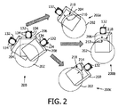
図2を参照すると、本発明の原理をさらに説明するために超音波撮像プロセスが分解される。関心領域202が撮像されるものとする。図200はプローブ132の位置と方向を決定するセンサ134を含む超音波プローブ132を示す。プローブ132が関心領域202に対して位置付けられると、複数の画像ボリューム204,206及び208が収集される。図200a,200b及び200cは画像200の分解を示す。図200a,200b及び200cにおける各ボリューム204,206,208は関心領域202にわたる仮定音速と実音速の差に起因する収差210,212,214を含む関心領域202の画像218を含む。収差210,212,214は本発明の原理に従って考慮される。
Referring to FIG. 2, the ultrasound imaging process is broken down to further illustrate the principles of the present invention. It is assumed that the region of
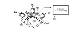
図3を参照すると、一実施形態において、各ボリューム204,206,208の画像218は画像218間のミスマッチを決定するために互いに対して比較され得る。そしてミスマッチはブロック220において収差(210,212及び214)を考慮するために利用される。
With reference to FIG. 3, in one embodiment, the
図4を参照すると、ブロック220のプロセスが一つの特に有用な実施形態に従ってより詳細に記載される。外部プローブ132はセンサ134によって追跡される。プローブ132の座標系224は関心領域202の座標系若しくは他の基準座標系、例えばCT,MRIなどによってとられる術前画像と関連する例えば大域座標系226へ、変換230を用いて変換され得る。プローブ132上のセンサ134は3D空間における画像ボリューム204,206及び208の3D位置及び方向を与える。大域座標系226に関して、任意の画像ボリューム204,206及び208における任意のボクセルの位置は任意の他の画像ボリュームにおける任意の他のピクセルのものに関連付けられ得る。
Referring to FIG. 4, the process of
位相収差補正モデル232はこれら関連付けられた画像218をとり、画像218の各々を補正する。アルゴリズムは二つ(以上)の画像にわたって対応する特徴をマッチングすることによってある画像における情報を別の画像において観察されるものに関連付ける。相関関係は二つ以上の画像218の間のベストフィット相関を探すことによって最適化され得る。アルゴリズムは位相収差歪曲/補正モデル(例えばスケーリングモデル、組織の密度及びそれらの変動を考慮するボクセルモデルなど)を含む。位相収差歪曲/補正モデルはベストフィット相関234を提供するか及び/又は履歴データ若しくは二つ以上の画像をフィッティングするために学習された他の情報を提示するために利用され得る。モデル最適化は様々なメトリックを異なる組み合わせで利用し得る。例えば、補正モデル232の最適化は相互情報量の最大化、エントロピーの最小化などの画像マッチングメトリックを計算することによって実行され得る。
The phase
図5を参照すると、別の実施形態において、各画像に対して受信されるUS信号を利用し、そしてある他の方向から受信される信号と応答をマッチングすることによって収差を最適化する代わりに若しくはそれに加えて、現在のUS画像302若しくは304がそれぞれ患者モデル306若しくは308(術前MRI,CT,統計的アトラスなど)にレジストレーション若しくはマッチングされ、レジストレーション/マッチングのために収集された情報が位相収差を最適化するために利用され得る。モデル306,308は'期待'信号応答を与えるために利用され得る。例えば、密度及び形状が特徴にわたる音速に対する影響について考慮され得る。モデル306,308は異なる組織の期待音速を組み込み、画像302,304における歪曲のライブ補正に役立ち得る。
Referring to FIG. 5, in another embodiment, instead of using the US signal received for each image and optimizing the aberrations by matching the response with the signal received from some other direction. Or in addition, the
図6を参照すると、追跡される手術器具、例えば機器102が別の補正法において利用され得る。本方法は本明細書に記載の他の方法に加えて、それと組み合わせて、若しくはその代わりに利用され得ることが理解されるべきである。外部追跡される手術器具102の位置決めは電磁追跡システム、光ファイバ追跡システム、形状検知システムなどの追跡システム(117、図1)を用いて実行され得る。機器102が追跡されるので、機器102はそれに対する収差が推定され補正され得る特徴として利用され得る。機器102の位置は補正のための制約として利用され得る。これは多くの応用において通常見られる通り、機器(例えば針、カテーテルなど)の一部が画像ボリューム(204,206,208)において見える場合に特に役立つ。構成320は収差を伴う機器102を示し、構成322は補正後の機器102を示す。
Referring to FIG. 6, a tracked surgical instrument such as
図7を参照すると、画像補正のためのシステム/方法が例示的に示される。ブロック402において、画像プローブが追跡され、異なる既知の位置から関心領域の画像ボリュームを生成する。画像プローブは関心領域へ/からの超音波パルス若しくは信号を送信及び受信する超音波プローブを含み得る。関心領域は患者の任意の内部組織若しくは臓器であり得る。他の画像技術もまた利用され得る。プローブは一つ以上の位置センサを用いて追跡され得る。位置センサは電磁センサを含み得るか、若しくは他の位置検知技術を利用し得る。
Referring to FIG. 7, a system / method for image correction is illustratively shown. At
ブロック404において、プローブに付随する医用画像装置からの画像信号が処理され、一つ以上の画像ボリュームを基準と比較する。比較は関心領域にわたる仮定波速度(全組織に対して一定であると仮定される)と関心領域にわたる補償波速度の間の収差を決定する。
At
ブロック406において、基準は関心領域の一つ以上の特徴を含み、異なる方向からの複数の画像ボリュームは一つ以上の特徴におけるミスマッチが収差を計算するために利用されるように座標系を用いて整列される。ブロック408において、追跡される医療機器が、医療機器の位置と方向が収差を計算する基準として利用され得るように画像中に配置され得る。
At
ブロック410において、基準はモデルを含み得る。関心領域の一つ以上の特徴は特徴ミスマッチが収差を計算するために利用されるようにモデルと比較される。モデルは三次元画像モダリティ(例えばCT,MRIなど)によって事前に生成される患者モデルを含み得る。モデルは画像を整列させる比較若しくは変換を提供するためにメモリに記憶される選択特徴点も含み得る。選択特徴点は現在の手順及び/又は他の患者での手順からの履歴若しくは学習データに基づいて決定されるか若しくは提供され得る。ブロック412において、一実施形態では、モデルは関心領域にわたる波速度データを含み(特定組織、領域などに対する異なる値を含む)、関心領域にわたる補償波速度を決定するためにこのデータを用いて調節を提供し得る。
At
ブロック414において、収差を減らし、補償波速度に基づいて表示用の補正画像を生成するために、画像信号が補正される。ブロック416において、駆動されるときに収差補正画像を表示するリアル若しくはバーチャルスイッチを含むことによって画像補償モードが有効にされ得る。駆動されるとき、スイッチは収差補償を可能にする。無効にされるとき、収差補償は補償されない。
At block 414, the image signal is corrected to reduce aberrations and generate a corrected image for display based on the compensated wave velocity. In
添付の請求項を解釈する際、以下のことが理解されるべきである:
a)"有する"という語は所与の請求項に列挙される以外の要素若しくは動作の存在を除外しない。
b)ある要素に先行する"a"若しくは"an"という語はかかる要素の複数の存在を除外しない。
c)請求項における任意の参照符号はその範囲を限定しない。
d)複数の"手段"は同じ項目又はハードウェア若しくはソフトウェア実装構造若しくは機能によってあらわされ得る。
e)特に指定しない限り動作の特定順序が要求されることは意図されない。
In interpreting the appended claims, the following should be understood:
a) the word “comprising” does not exclude the presence of other elements or acts than those listed in a given claim;
b) The word “a” or “an” preceding an element does not exclude the presence of a plurality of such elements.
c) any reference signs in the claims do not limit their scope;
d) Multiple "means" may be represented by the same item or hardware or software implementation structure or function.
e) It is not intended that a specific order of operations be required unless otherwise specified.
画像ガイドインターベンションのための術中画像補正のためのシステムと方法に対する好適な実施形態が記載されているが(これらは例示であって限定のつもりではない)、上記教示に照らして当業者によって修正及び変更がなされ得ることが留意される。従って添付の請求項によって概説される通り本明細書に開示の実施形態の範囲内にある開示の実施形態の特定の実施形態において変更がなされ得ることが理解されるものとする。特許法によって要求される細部と詳細がこのように記載されているが、特許証によって保護されることが望まれる特許請求の範囲は添付の請求項において記載される。 While preferred embodiments for systems and methods for intraoperative image correction for image guided intervention are described (these are exemplary and not intended to be limiting), modifications will occur to those skilled in the art in light of the above teachings It is noted that changes can be made. Accordingly, it is to be understood that changes may be made in particular embodiments of the disclosed embodiments that are within the scope of the embodiments disclosed herein as outlined by the appended claims. Although the details and details required by the patent law are thus described, the scope of the claims that are desired to be protected by Letters Patent is set forth in the appended claims.
Claims (15)
異なる位置から関心領域の画像ボリュームを生成する、追跡される画像プローブと、
前記プローブに付随する医用画像装置からの画像信号を処理し、一つ以上の画像ボリュームを基準と比較して前記関心領域にわたる仮定波速度と前記関心領域にわたる補償波速度の間の収差を決定する、画像補償モジュールと、
前記画像補償モジュールによって決定される収差を受信し、前記補償波速度に基づいて表示用の補正画像を生成する、画像補正モジュールとを有する、画像補正システム。 An image correction system,
A tracked image probe that generates an image volume of the region of interest from different locations;
Process an image signal from a medical imaging device associated with the probe and compare one or more image volumes to a reference to determine an aberration between an assumed wave velocity over the region of interest and a compensated wave velocity over the region of interest. The image compensation module,
An image correction system comprising: an image correction module that receives an aberration determined by the image compensation module and generates a corrected image for display based on the compensation wave velocity.
プロセッサと、
前記プロセッサに結合するメモリと、
画像プローブからの画像信号を受信する、前記プロセッサに結合する画像装置であって、前記画像プローブが異なる位置から関心領域の画像ボリュームを生成するように構成される、画像装置とを有し、
前記メモリが、
前記画像装置からの画像信号を処理し、一つ以上の画像ボリュームを基準と比較して前記関心領域にわたる仮定波速度と前記関心領域にわたる補償波速度の間の収差を決定する、画像補償モジュールと、
前記画像補償モジュールによって決定される収差を受信し、前記補償波速度に基づいて表示用の補正画像を生成する、画像補正モジュールとを含む、
ワークステーション。 A workstation,
A processor;
A memory coupled to the processor;
An image device coupled to the processor for receiving an image signal from an image probe, wherein the image probe is configured to generate an image volume of a region of interest from a different location;
The memory is
An image compensation module that processes an image signal from the imaging device and compares one or more image volumes with a reference to determine an aberration between an assumed wave velocity over the region of interest and a compensation wave velocity over the region of interest; ,
Receiving an aberration determined by the image compensation module and generating a corrected image for display based on the compensation wave velocity,
Work station.
追跡される画像プローブにより生成される、異なる既知の位置から関心領域の画像ボリュームを収集するステップと、
前記プローブに付随する医用画像装置からの画像信号を処理し、一つ以上の画像ボリュームを基準と比較して前記関心領域にわたる仮定波速度と前記関心領域にわたる補償波速度の間の収差を決定する、ステップと、
前記画像信号を補正して、前記収差を減らし前記補償波速度に基づいて表示用の補正画像を生成するステップとを有する方法。 A method of operating a system for image correction, comprising:
Collecting image volumes of a region of interest from different known locations generated by a tracked image probe;
Process an image signal from a medical imaging device associated with the probe and compare one or more image volumes to a reference to determine an aberration between an assumed wave velocity over the region of interest and a compensated wave velocity over the region of interest. , Steps and
Correcting the image signal to reduce the aberration and generating a corrected image for display based on the compensated wave velocity.
Applications Claiming Priority (3)
| Application Number | Priority Date | Filing Date | Title |
|---|---|---|---|
| US201161503666P | 2011-07-01 | 2011-07-01 | |
| US61/503,666 | 2011-07-01 | ||
| PCT/IB2012/053238 WO2013005136A1 (en) | 2011-07-01 | 2012-06-27 | Intra-operative image correction for image-guided interventions |
Publications (3)
| Publication Number | Publication Date |
|---|---|
| JP2014518123A JP2014518123A (en) | 2014-07-28 |
| JP2014518123A5 JP2014518123A5 (en) | 2015-07-09 |
| JP6085598B2 true JP6085598B2 (en) | 2017-02-22 |
Family
ID=46796689
Family Applications (1)
| Application Number | Title | Priority Date | Filing Date |
|---|---|---|---|
| JP2014518020A Expired - Fee Related JP6085598B2 (en) | 2011-07-01 | 2012-06-27 | Intraoperative image correction for image guided intervention |
Country Status (6)
| Country | Link |
|---|---|
| US (1) | US20140147027A1 (en) |
| EP (1) | EP2726899A1 (en) |
| JP (1) | JP6085598B2 (en) |
| CN (1) | CN103765239B (en) |
| MX (1) | MX2013015358A (en) |
| WO (1) | WO2013005136A1 (en) |
Families Citing this family (15)
| Publication number | Priority date | Publication date | Assignee | Title |
|---|---|---|---|---|
| KR102207919B1 (en) * | 2013-06-18 | 2021-01-26 | 삼성전자주식회사 | Method, apparatus and system for generating ultrasound |
| CN105451663B (en) * | 2013-06-28 | 2019-03-19 | 皇家飞利浦有限公司 | Guidance is fed back to the ultrasound acquisition of target view |
| CN103445765B (en) * | 2013-09-24 | 2015-08-26 | 南京大学 | A kind of method that in photoacoustic imaging, the velocity of sound is corrected |
| CN104042244A (en) * | 2014-05-05 | 2014-09-17 | 苏州森斯凌传感技术有限公司 | Ultrasonic probe detection system based on host machine algorithm processing |
| CN105433977B (en) * | 2014-07-31 | 2020-02-07 | 东芝医疗系统株式会社 | Medical imaging system, surgical guidance system, and medical imaging method |
| JP6411185B2 (en) | 2014-11-19 | 2018-10-24 | キヤノンメディカルシステムズ株式会社 | Ultrasonic diagnostic equipment |
| DE102015114755A1 (en) | 2015-09-03 | 2017-03-09 | Phoenix Contact Gmbh & Co. Kg | Safe photovoltaic system |
| JP6876065B2 (en) * | 2015-12-14 | 2021-05-26 | ニューヴェイジヴ,インコーポレイテッド | 3D visualization during surgery with reduced radiation |
| WO2017114701A1 (en) * | 2015-12-31 | 2017-07-06 | Koninklijke Philips N.V. | System and method for interventional acoustic imaging |
| CN109219384B (en) * | 2016-05-31 | 2022-04-12 | 皇家飞利浦有限公司 | Image-based fusion of endoscopic images and ultrasound images |
| US20180049808A1 (en) * | 2016-08-17 | 2018-02-22 | Covidien Lp | Method of using soft point features to predict breathing cycles and improve end registration |
| US10299699B2 (en) * | 2016-11-28 | 2019-05-28 | Biosense Webster (Israel) Ltd. | Computerized tomography image correction |
| JP6745998B2 (en) * | 2016-12-16 | 2020-08-26 | コーニンクレッカ フィリップス エヌ ヴェKoninklijke Philips N.V. | System that provides images to guide surgery |
| US11457981B2 (en) | 2018-10-04 | 2022-10-04 | Acclarent, Inc. | Computerized tomography (CT) image correction using position and direction (P andD) tracking assisted optical visualization |
| JP7370903B2 (en) | 2020-02-28 | 2023-10-30 | キヤノン株式会社 | Ultrasonic diagnostic equipment, learning equipment, image processing methods and programs |
Family Cites Families (7)
| Publication number | Priority date | Publication date | Assignee | Title |
|---|---|---|---|---|
| DE10115341A1 (en) * | 2001-03-28 | 2002-10-02 | Philips Corp Intellectual Pty | Method and imaging ultrasound system for determining the position of a catheter |
| JP4958348B2 (en) * | 2001-09-06 | 2012-06-20 | 株式会社日立メディコ | Ultrasonic imaging device |
| US7379769B2 (en) * | 2003-09-30 | 2008-05-27 | Sunnybrook Health Sciences Center | Hybrid imaging method to monitor medical device delivery and patient support for use in the method |
| US20060110071A1 (en) * | 2004-10-13 | 2006-05-25 | Ong Sim H | Method and system of entropy-based image registration |
| US10143398B2 (en) * | 2005-04-26 | 2018-12-04 | Biosense Webster, Inc. | Registration of ultrasound data with pre-acquired image |
| US7604601B2 (en) * | 2005-04-26 | 2009-10-20 | Biosense Webster, Inc. | Display of catheter tip with beam direction for ultrasound system |
| DE502005004140D1 (en) * | 2005-11-11 | 2008-06-26 | Brainlab Ag | Determination of sound velocity factors in ultrasound images of a body |
-
2012
- 2012-06-27 CN CN201280041997.4A patent/CN103765239B/en not_active Expired - Fee Related
- 2012-06-27 WO PCT/IB2012/053238 patent/WO2013005136A1/en active Application Filing
- 2012-06-27 EP EP12754094.6A patent/EP2726899A1/en not_active Withdrawn
- 2012-06-27 MX MX2013015358A patent/MX2013015358A/en not_active Application Discontinuation
- 2012-06-27 US US14/127,608 patent/US20140147027A1/en not_active Abandoned
- 2012-06-27 JP JP2014518020A patent/JP6085598B2/en not_active Expired - Fee Related
Also Published As
| Publication number | Publication date |
|---|---|
| CN103765239B (en) | 2017-04-19 |
| CN103765239A (en) | 2014-04-30 |
| MX2013015358A (en) | 2014-02-11 |
| WO2013005136A1 (en) | 2013-01-10 |
| JP2014518123A (en) | 2014-07-28 |
| EP2726899A1 (en) | 2014-05-07 |
| US20140147027A1 (en) | 2014-05-29 |
Similar Documents
| Publication | Publication Date | Title |
|---|---|---|
| JP6085598B2 (en) | Intraoperative image correction for image guided intervention | |
| US10674891B2 (en) | Method for assisting navigation of an endoscopic device | |
| US11547481B2 (en) | Systems and methods for laparoscopic planning and navigation | |
| JP2023053108A (en) | Image registration and guidance using concurrent x-plane imaging | |
| US10575755B2 (en) | Computer-implemented technique for calculating a position of a surgical device | |
| JP6782688B2 (en) | Intelligent and real-time visualization of instruments and anatomy in 3D imaging workflows for intervention procedures | |
| JP6290372B2 (en) | Localization of robot remote motion center point using custom trocar | |
| US8213693B1 (en) | System and method to track and navigate a tool through an imaged subject | |
| US8126239B2 (en) | Registering 2D and 3D data using 3D ultrasound data | |
| Nakamoto et al. | Intraoperative magnetic tracker calibration using a magneto-optic hybrid tracker for 3-D ultrasound-based navigation in laparoscopic surgery | |
| US20140100452A1 (en) | Ultrasound-image-guide system and volume-motion-base calibration method | |
| JP2008126075A (en) | System and method for visual verification of ct registration and feedback | |
| US10952705B2 (en) | Method and system for creating and utilizing a patient-specific organ model from ultrasound image data | |
| Gergel et al. | An electromagnetic navigation system for transbronchial interventions with a novel approach to respiratory motion compensation | |
| JP6612873B2 (en) | Automatic selection of optimal calibration in tracking interventional procedures | |
| Mori et al. | Compensation of electromagnetic tracking system using an optical tracker and its application to brochoscopy navigation system | |
| Shahin et al. | Ultrasound-based tumor movement compensation during navigated laparoscopic liver interventions | |
| US20200390417A1 (en) | Ultrasound tracking and visualization | |
| US20230215059A1 (en) | Three-dimensional model reconstruction | |
| US20230230263A1 (en) | Two-dimensional image registration | |
| US20230190382A1 (en) | Directing an ultrasound probe using known positions of anatomical structures |
Legal Events
| Date | Code | Title | Description |
|---|---|---|---|
| A521 | Request for written amendment filed |
Free format text: JAPANESE INTERMEDIATE CODE: A523 Effective date: 20150520 |
|
| A621 | Written request for application examination |
Free format text: JAPANESE INTERMEDIATE CODE: A621 Effective date: 20150520 |
|
| A977 | Report on retrieval |
Free format text: JAPANESE INTERMEDIATE CODE: A971007 Effective date: 20160316 |
|
| A131 | Notification of reasons for refusal |
Free format text: JAPANESE INTERMEDIATE CODE: A131 Effective date: 20160502 |
|
| A521 | Request for written amendment filed |
Free format text: JAPANESE INTERMEDIATE CODE: A523 Effective date: 20160802 |
|
| TRDD | Decision of grant or rejection written | ||
| A01 | Written decision to grant a patent or to grant a registration (utility model) |
Free format text: JAPANESE INTERMEDIATE CODE: A01 Effective date: 20170105 |
|
| A61 | First payment of annual fees (during grant procedure) |
Free format text: JAPANESE INTERMEDIATE CODE: A61 Effective date: 20170130 |
|
| R150 | Certificate of patent or registration of utility model |
Ref document number: 6085598 Country of ref document: JP Free format text: JAPANESE INTERMEDIATE CODE: R150 |
|
| LAPS | Cancellation because of no payment of annual fees |