JP5481237B2 - Magnetic resonance imaging system - Google Patents
Magnetic resonance imaging system Download PDFInfo
- Publication number
- JP5481237B2 JP5481237B2 JP2010053681A JP2010053681A JP5481237B2 JP 5481237 B2 JP5481237 B2 JP 5481237B2 JP 2010053681 A JP2010053681 A JP 2010053681A JP 2010053681 A JP2010053681 A JP 2010053681A JP 5481237 B2 JP5481237 B2 JP 5481237B2
- Authority
- JP
- Japan
- Prior art keywords
- coordinate system
- image data
- image
- subject
- imaging
- Prior art date
- Legal status (The legal status is an assumption and is not a legal conclusion. Google has not performed a legal analysis and makes no representation as to the accuracy of the status listed.)
- Expired - Fee Related
Links
Images


Landscapes
- Magnetic Resonance Imaging Apparatus (AREA)
Description
本発明は、磁気共鳴イメージング装置(Magnetic Resonance Imaging Apparatus:以下適宜、MRI装置と略記する)などの医用画像診断装置に関する。特に本発明は、MRI装置などの医用画像診断装置において、患者の体位情報を撮像画像と共に表示する技術に関する。 The present invention relates to a medical image diagnostic apparatus such as a magnetic resonance imaging apparatus (hereinafter abbreviated as an MRI apparatus as appropriate). In particular, the present invention relates to a technique for displaying patient posture information together with a captured image in a medical image diagnostic apparatus such as an MRI apparatus.
磁気共鳴イメージングは、静磁場中に置かれた被検体の原子核スピンをラーモア周波数の高周波パルス(radio frequency pulse:以下、RFパルスという)で磁気的に励起し、この励起に伴って発生する核磁気共鳴信号(nuclear magnetic resonance signal:以下、MR信号という)から画像を再構成する撮像法である。 In magnetic resonance imaging, the nuclear spin of a subject placed in a static magnetic field is magnetically excited with a radio frequency pulse (hereinafter referred to as an RF pulse) having a Larmor frequency, and the nuclear magnetism generated by the excitation is generated. In this imaging method, an image is reconstructed from a resonance signal (hereinafter referred to as an MR signal).
この磁気共鳴イメージングなどを用いた医用画像診断装置では、装置を利用する上での位置や角度を示すために、装置を中心に互いに直交する3座標軸からなる3次元座標系が定義される。この座標系は、装置に固有の座標系であり、「装置座標系」と呼ばれる。しかし、被検体である患者は様々な姿勢で撮像されるため、診断を行う上では、患者の体位や方向を基準にした座標系が装置座標系とは別に設定される。 In a medical image diagnostic apparatus using magnetic resonance imaging or the like, a three-dimensional coordinate system composed of three coordinate axes orthogonal to each other is defined around the apparatus in order to indicate the position and angle in using the apparatus. This coordinate system is a coordinate system unique to the apparatus, and is called an “apparatus coordinate system”. However, since the patient, who is the subject, is imaged in various postures, a coordinate system based on the patient's body position and direction is set separately from the apparatus coordinate system for diagnosis.
そこで、医用画像診断装置では、背臥位(仰向け)、腹臥位(うつ伏せ)、右側臥位、左側臥位といった患者の体位と、頭から或いは足からといった装置への挿入方向とに基づいて決められる可変的な座標系が撮像毎に定義される。この座標系は、患者の撮像時の姿勢に基づいて決められる座標系であり、「患者座標系」と呼ばれる。そして、患者の体位や方向に関連した従来技術として、以下の特許文献1が知られている。
Therefore, in the medical image diagnostic apparatus, based on the patient's body position such as the supine position (suppose), the prone position (prone position), the right side position, and the left side position, and the insertion direction from the head or the foot to the apparatus. A variable coordinate system to be determined is defined for each imaging. This coordinate system is a coordinate system determined based on the posture at the time of imaging of the patient, and is called a “patient coordinate system”. And the following
特許文献1の発明では、撮像画像における被検体領域に重ならないように、撮像画像の四隅の小さめの領域に、患者の方向情報をそれぞれ埋め込んでいる。方向情報の埋め込みは、上記の四隅の領域の画像データを方向情報に置き換えるものである。なお、特許文献1の発明では、撮像画像のファイルがDICOMに従って構成され、撮像画像の四隅に埋め込まれた方向情報とは別に、ファイルの付帯情報の一部を構成する撮像条件に患者の方向情報が含まれることを前提としている。上記DICOMは、ネットワーク規格である「Digital Imaging and Communications in Medicine」のことである。
In the invention of
特許文献1の発明では、撮像画像の四隅に埋め込まれた方向情報と、ファイルの付帯情報に含まれる方向情報(以下、DICOM方向情報という)とが一致しないファイルのリストを作成している。そして、両者が一致しない場合、必要に応じてユーザが不一致リストに挙げられたファイルの撮像画像およびDICOM方向情報を表示させ、ユーザがファイル毎に方向情報を補正することを前提としている。
In the invention of
しかし、MRI装置などの医用画像診断装置では一度の検査で多数の撮像画像が生成されるため、全ての撮像画像において被検体の体位情報を正しく表示させようとした場合、ユーザの負担が大きくなる。このため、医用画像診断装置による撮像によって多数の画像ファイルを生成する場合に、ユーザに大きな負担を与えることなく、撮像画像に付随する体位情報を従来よりも正確にする技術が要望されていた。 However, a medical image diagnostic apparatus such as an MRI apparatus generates a large number of captured images in a single examination. Therefore, if the posture information of the subject is correctly displayed in all captured images, the burden on the user increases. . For this reason, when many image files are produced | generated by the imaging by a medical image diagnostic apparatus, the technique which makes the posture information accompanying a picked-up image more accurate than before is requested | required, without giving a big burden to a user.
本発明の目的は、MRI装置などの医用画像診断装置において複数の撮像を行う場合に、ユーザに大きな負担を与えることなく、撮像画像に付随する被検体の体位情報を従来よりも正確にする技術を提供することである。 An object of the present invention is a technique for making the posture information of a subject associated with a captured image more accurate than before without giving a heavy burden to the user when performing a plurality of imaging in a medical image diagnostic apparatus such as an MRI apparatus. Is to provide.
本発明に係るMRI装置は、装置座標系に基づく磁気共鳴イメージングである撮像動作を被検体に対して複数回行うことで、各々の前記撮像動作にそれぞれ対応する複数の画像データを生成するものであって、ズレ量設定部と、体位情報設定部とを備える。 An MRI apparatus according to the present invention generates a plurality of image data corresponding to each of the imaging operations by performing an imaging operation, which is magnetic resonance imaging based on the apparatus coordinate system, a plurality of times on a subject. A displacement amount setting unit and a posture information setting unit are provided.
本発明のMRI装置の一形態では、前記ズレ量設定部は、先に行われた前記撮像動作で生成された前記画像データおよび入力情報に応じて、後に行われる前記撮像動作で生成される前記画像データにおける、前記被検体の体位に基づく人体座標系と前記装置座標系とのズレ量を設定し、前記体位情報設定部は、前記ズレ量が設定された前記画像データに付随する前記被検体の体位情報を前記ズレ量に基づいて補正する。 In an aspect of the MRI apparatus of the present invention, the deviation amount setting unit is generated in the imaging operation performed later according to the image data and input information generated in the imaging operation performed earlier. A deviation amount between the human body coordinate system based on the posture of the subject in the image data and the apparatus coordinate system is set, and the posture information setting unit is configured to attach the subject to the image data in which the deviation amount is set. Is corrected based on the amount of deviation.
本発明のMRI装置の別の形態では、前記ズレ量設定部は、選択された前記画像データおよび入力情報に応じて、この選択された前記画像データとは別の前記画像データにおける、前記被検体の体位に基づく人体座標系と前記装置座標系とのズレ量を設定し、前記体位情報設定部は、前記ズレ量が設定された前記画像データに付随する前記被検体の体位情報を前記ズレ量に基づいて補正する。 In another aspect of the MRI apparatus of the present invention, the deviation amount setting unit is configured to detect the subject in the image data different from the selected image data according to the selected image data and input information. The position information setting unit sets a shift amount between the human body coordinate system based on the posture of the subject and the apparatus coordinate system, and the posture information setting unit sets the shift amount of the posture information of the subject associated with the image data in which the shift amount is set. Correct based on
本発明のMRI装置のさらに別の形態では、前記ズレ量設定部は、選択された前記画像データおよび入力情報に応じて、この選択された前記画像データとは別の前記画像データにおける、前記被検体の体位に基づく人体座標系と前記装置座標系とのズレ量を設定し、前記体位情報設定部は、前記ズレ量に基づいて前記被検体の体位情報を生成し、前記ズレ量が設定された前記画像データに前記体位情報を付随させる。 According to still another aspect of the MRI apparatus of the present invention, the deviation amount setting unit is configured to detect the coverage in the image data different from the selected image data according to the selected image data and input information. A deviation amount between the human body coordinate system based on the posture of the specimen and the apparatus coordinate system is set, and the posture information setting unit generates the posture information of the subject based on the deviation amount, and the deviation amount is set. The posture information is attached to the image data.
本発明によれば、MRI装置などの医用画像診断装置において複数の撮像を行う場合に、ユーザに大きな負担を与えることなく、撮像画像に付随する被検体の体位情報を従来よりも正確にすることができる。 According to the present invention, when performing a plurality of imaging in a medical image diagnostic apparatus such as an MRI apparatus, the posture information of the subject accompanying the captured image is made more accurate than before without imposing a heavy burden on the user. Can do.
以下、本発明の実施形態を添付図面に基づいて説明する。なお、各図において同一要素には同一符号を付し、重複する説明を省略する。 Hereinafter, embodiments of the present invention will be described with reference to the accompanying drawings. In addition, in each figure, the same code | symbol is attached | subjected to the same element and the overlapping description is abbreviate | omitted.
<第1の実施形態>
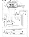
図1は、第1の実施形態におけるMRI装置20の全体構成を示すブロック図である。図1に示すように、MRI装置20は、静磁場を形成する筒状の静磁場用磁石22と、静磁場用磁石22の内側において軸を同じにして設けられた筒状のシムコイル24と、傾斜磁場コイル26と、RFコイル28と、制御系30と、被検体Pが乗せられる寝台32と、投光器34とを備える。
<First Embodiment>
FIG. 1 is a block diagram showing the overall configuration of the
ここでは一例として、MRI装置20における装置座標系の互いに直交するX軸、Y軸、Z軸について以下のように定義する。まず、静磁場用磁石22およびシムコイルユニット24は、それらの軸方向が鉛直方向に直交するように配置されているものとし、静磁場用磁石22およびシムコイルユニット24の軸方向をZ軸方向とする。また、鉛直方向をY軸方向とし、寝台32は、その天板の載置用の面の法線方向がY軸方向となるように配置されているものとする。
Here, as an example, the X-axis, Y-axis, and Z-axis that are orthogonal to each other in the apparatus coordinate system of the
制御系30は、静磁場電源40と、シムコイル電源42と、傾斜磁場電源44と、RF送信器46と、RF受信器48と、寝台位置制御装置49と、シーケンスコントローラ50と、コンピュータ52とを備える。
The
傾斜磁場電源44は、X軸傾斜磁場電源44xと、Y軸傾斜磁場電源44yと、Z軸傾斜磁場電源44zとで構成されている。また、コンピュータ52は、演算装置60と、入力装置62と、表示装置64と、記憶装置66とで構成されている。
The gradient magnetic
静磁場用磁石22は、静磁場電源40に接続され、静磁場電源40から供給された電流により撮像領域に静磁場を形成させる。シムコイル24は、シムコイル電源42に接続され、シムコイル電源42から供給される電流により、この静磁場を均一化する。静磁場用磁石22は、超伝導コイルで構成される場合が多く、励磁の際に静磁場電源40に接続されて電流が供給されるが、一旦励磁された後は非接続状態とされるのが一般的である。なお、静磁場電源40を設けずに、静磁場用磁石22を永久磁石で構成してもよい。
The static
傾斜磁場コイル26は、X軸傾斜磁場コイル26xと、Y軸傾斜磁場コイル26yと、Z軸傾斜磁場コイル26zとで構成され、静磁場用磁石22の内側で筒状に形成されている。X軸傾斜磁場コイル26x、Y軸傾斜磁場コイル26y、Z軸傾斜磁場コイル26zはそれぞれ、傾斜磁場電源44のX軸傾斜磁場電源44x、Y軸傾斜磁場電源44y、Z軸傾斜磁場電源44zに接続される。そして、X軸傾斜磁場電源44x、Y軸傾斜磁場電源44y、Z軸傾斜磁場電源44zからX軸傾斜磁場コイル26x、Y軸傾斜磁場コイル26y、Z軸傾斜磁場コイル26zにそれぞれ供給される電流により、X軸方向の傾斜磁場Gx、Y軸方向の傾斜磁場Gy、Z軸方向の傾斜磁場Gzが撮像領域にそれぞれ形成される。
The gradient
RF送信器46は、シーケンスコントローラ50から入力される制御情報に基づいて、核磁気共鳴を起こすためのラーモア周波数のRFパルス(RF電流パルス)を生成し、これを送信用のRFコイル28に送信する。RFコイル28には、ガントリに内蔵されたRFパルスの送受信用の全身用コイル(WBC:whole body coil)や、寝台32または被検体Pの近傍に設けられるRFパルスの受信用の局所コイルなどがある。送信用のRFコイル28は、RF送信器46からRFパルスを受けて被検体Pに送信する。受信用のRFコイル28は、被検体Pの内部の原子核スピンがRFパルスによって励起されることで発生したMR信号(高周波信号)を受信し、このMR信号は、RF受信器48により検出される。
The
RF受信器48は、検出したMR信号に位相検波、フィルタリングなどの各種の信号処理を施した後、A/D(analog to digital)変換を施すことで、デジタル化された複素データである生データ(raw data)を生成する。RF受信器48は、生成したMR信号の生データをシーケンスコントローラ50に入力する。
The
投光器34は、ガントリにおける寝台32の入口部に取り付けられており、撮像部位の位置設定の際に被検体Pの撮像部位に光を当てる。
The
演算装置60は、MRI装置20全体のシステム制御を行うものであり、これについては後述の図2を用いて説明する。
The
シーケンスコントローラ50は、演算装置60の指令に従って、傾斜磁場電源44、RF送信器46およびRF受信器48を駆動させるために必要な制御情報を記憶する。ここでの制御情報とは、例えば、傾斜磁場電源44に印加すべきパルス電流の強度や印加時間、印加タイミング等の動作制御情報を記述したシーケンス情報である。シーケンスコントローラ50は、記憶した所定のシーケンスに従って傾斜磁場電源44、RF送信器46およびRF受信器48を駆動させることにより、X軸傾斜磁場Gx、Y軸傾斜磁場Gy,Z軸傾斜磁場GzおよびRFパルスを発生させる。
The
また、シーケンスコントローラ50は、RF受信器48から入力されるMR信号の生データを受けて、これを演算装置60に入力する。さらに、シーケンスコントローラ50は、演算装置60の指令に従って寝台位置制装置49を駆動し、被検体Pの撮像部位が磁場中心下に置かれるように、被検体Pが乗せられた寝台32の位置を制御する。また、シーケンスコントローラ50は、演算装置60の指令に従い、不図示の配線で接続された投光器34を制御する。
Further, the
図2は、図1に示すMRI装置20のコンピュータ52の詳細、特に演算装置60の詳細を示す機能ブロック図である。図2に示すように、演算装置60は、MPU(Micro Processor Unit)70と、ズレ量設定部72と、表示制御部74と、画像再構成部76と、画像処理部78と、システムバス80とを備える。
FIG. 2 is a functional block diagram showing details of the
MPU70は、撮像条件の設定、撮像動作および撮像後の画像表示において、システムバス80等の配線を介してMRI装置20全体のシステム制御を行う。
The
入力装置62は、撮像条件や画像処理条件を設定する機能をユーザに提供する。また、入力装置62は、装置座標系の座標軸と、患者座標系の座標軸との傾きを(例えばマウス操作によって)入力する機能をユーザに提供する。
The
ズレ量設定部72は、MRI装置20がマニュアルモードに設定されている場合、ユーザにより入力される装置座標系と患者座標系の各座標軸の傾きに基づいて、両座標系の座標軸の傾き角度を算出および記憶する。ズレ量設定部72は、MRI装置20が自動モードに設定されている場合、画像処理部78から入力される被検体Pの各体内組織の領域の位置に基づいて、両座標系の座標軸の傾き角度を算出および記憶する。
When the
画像再構成部76は、シーケンスコントローラ50から入力されるMR信号の生データに公知の2次元フーリエ変換等の処理を施して、被検体Pの各スライスの画像データを生成する。画像再構成部76は、生成した画像データを画像処理部78に入力する。
The
画像処理部78は、画像再構成部76から入力される画像データに所定の画像処理を施し、画像処理後の画像データを記憶装置66に記憶させる。また、画像処理部78は、両座標系の座標軸の傾き角度が設定された撮像動作で生成された画像データに付随する被検体Pの体位情報を、傾き角度に基づいて補正する。MRI装置20が自動モードに設定されている場合、画像処理部78は、画像データにおける被検体Pの体内の特定組織の領域を抽出し、その位置をズレ量設定部72に入力する。
The
記憶装置66は、画像再構成部76により生成され、画像処理部78により画像処理が施された画像データに対し、その画像データの生成に用いた撮像条件および患者情報を付帯情報として付属させて記憶する。
The
表示制御部74は、撮像により生成された画像データを画像として体位情報と共に表示装置64に表示させる。
The
ここで、本実施形態では一例として、患者座標系のX軸、Y軸、Z軸を以下のように定義する。被検体Pの左右方向をX軸方向とし、腹側を前、背中側を後ろとした被検体Pの前後方向をY軸方向とする。また、およそ背骨延在方向に頭を上、足を下とした被検体Pの上下方向をZ軸方向とする。また、患者座標系のX−Y平面をアキシャル面(Axial Plane)、患者座標系のX−Z平面をコロナル面(Coronal Plane)、患者座標系のY−Z平面をサジタル面(Sagittal Plane)とする。また、本実施形態では一例として、MRI装置20のガントリ内の磁場中心が装置座標系の原点であるものとし、説明を分かり易くするため、患者座標系の原点と装置座標系の原点とが同じであるものとして説明する。
Here, in this embodiment, as an example, the X axis, the Y axis, and the Z axis of the patient coordinate system are defined as follows. The left-right direction of the subject P is taken as the X-axis direction, and the front-rear direction of the subject P with the ventral side as the front and the back side as the back is taken as the Y-axis direction. In addition, the vertical direction of the subject P with the head up and the foot down in the spine extending direction is defined as the Z-axis direction. Also, the XY plane of the patient coordinate system is an axial plane, the XZ plane of the patient coordinate system is a coronal plane, and the YZ plane of the patient coordinate system is a sagittal plane. To do. In the present embodiment, as an example, the magnetic field center in the gantry of the
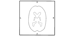
次に、装置座標系のX−Y平面、X−Z平面、Y−Z平面(以下、装置座標系の直交3平面という)の各断面像を示す図3、図4、図5を用いて、装置座標系の座標軸と、患者座標系の座標軸との傾きの入力操作について説明する。なお、図3〜図5は、被検体Pがその上下方向を寝台32の長手方向(装置座標系のZ軸方向)にほぼ沿って仰向け(背臥位)に寝ている場合を想定したものである。従って、装置座標系と患者座標系との座標軸の傾きを無視すれば、患者座標系では、図3はアキシャル断面像に対応し、図4はコロナル断面像に対応し、図5はサジタル断面像に対応する。 Next, FIGS. 3, 4, and 5 showing cross-sectional images of the XY plane, the XZ plane, and the YZ plane (hereinafter referred to as three orthogonal planes of the apparatus coordinate system) of the apparatus coordinate system are used. An operation for inputting the inclination between the coordinate axis of the apparatus coordinate system and the coordinate axis of the patient coordinate system will be described. 3 to 5 assume a case where the subject P is lying on his / her back (backward position) substantially along the longitudinal direction of the bed 32 (Z-axis direction of the apparatus coordinate system) in the vertical direction. It is. Therefore, if the inclination of the coordinate axes of the apparatus coordinate system and the patient coordinate system is ignored, in the patient coordinate system, FIG. 3 corresponds to an axial cross-sectional image, FIG. 4 corresponds to a coronal cross-sectional image, and FIG. Corresponding to
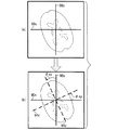
図3は、装置座標系のX−Y平面における頭部断面像を用いた装置座標系の座標軸と、患者座標系の座標軸との傾きの設定操作の一例を示す説明図である。図3(a)は、ユーザによる操作前の断面像の一例を示す模式図であり、図3(b)は、断面像上に重畳表示された患者座標系の座標軸を回転させた後の状態の一例を示す模式図である。 FIG. 3 is an explanatory diagram showing an example of an operation for setting the inclination between the coordinate axis of the apparatus coordinate system and the coordinate axis of the patient coordinate system using the head cross-sectional image in the XY plane of the apparatus coordinate system. FIG. 3A is a schematic diagram illustrating an example of a cross-sectional image before the operation by the user, and FIG. 3B is a state after rotating the coordinate axes of the patient coordinate system superimposed and displayed on the cross-sectional image. It is a schematic diagram which shows an example.
図3(a)、図(b)に示すように、装置座標系のX−Y平面の断面像上には、画像の中心を通るように、且つ、画像の縦方向または横方向に沿って、装置座標系のX軸90xおよび装置座標系のY軸90yが実線で重畳表示されている。装置座標系のX軸90x、Y軸90yの交点である装置座標系の原点は、画像の中心に位置する。図3(a)では、ユーザによる操作前であるため識別できないが、患者座標系のX軸94x、Y軸94yはそれぞれ、装置座標系のX軸90x、Y軸90yと同じ位置に重なっている。
As shown in FIGS. 3A and 3B, on the cross-sectional image on the XY plane of the apparatus coordinate system, it passes through the center of the image and along the vertical or horizontal direction of the image. The
ユーザは、断面像を表示装置64(図1参照)上に見ながら、入力装置62を介した回転操作により、破線で示す患者座標系のX軸94x、Y軸94yを、装置座標系のX軸90x、Y軸90yから傾けることができる。ここでの回転の中心は、装置座標系のX軸90x、Y軸90yの交点(患者座標系のX軸94x、Y軸94yの交点)である。図3(b)は、このようにして装置座標系のX軸90xと患者座標系のX軸94xとの傾きと、装置座標系のY軸90yと患者座標系のY軸94yとの傾きとを入力した状態を示す。
While viewing the cross-sectional image on the display device 64 (see FIG. 1), the user rotates the X-axis 94x and Y-
なお、ここでは操作の簡単化のため、表示制御部74は、装置座標系のX−Y平面上における直交状態を維持したまま、入力に基づいて患者座標系のX軸94x、Y軸94yを連動して回転させる。ズレ量設定部72は、この入力に基づいて、装置座標系のX−Y平面上における両座標系のX軸90x、94xの傾き角度θxy(両座標系のY軸90y、94yの傾き角度でもある)が何°であるかを算出し、記憶する。ここで、傾き角度θxyの末尾「xy」は、装置座標系の「X−Y平面」で設定された傾き角度であることを意味する(後述のθxz、θyzについても同様)。
Here, for simplification of operation, the
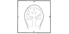
図4は、装置座標系のX−Z平面における頭部断面像を用いた装置座標系の座標軸と、患者座標系の座標軸との傾きの設定操作の一例を示す説明図である。図4(a)は、ユーザによる操作前の断面像の一例を示す模式図であり、図4(b)は、断面像上に重畳表示された患者座標系の各座標軸を回転させた後の状態の一例を示す模式図である。 FIG. 4 is an explanatory diagram illustrating an example of an operation for setting an inclination between the coordinate axis of the apparatus coordinate system and the coordinate axis of the patient coordinate system using the head cross-sectional image in the XZ plane of the apparatus coordinate system. FIG. 4A is a schematic diagram showing an example of a cross-sectional image before operation by the user, and FIG. 4B is a diagram after rotating each coordinate axis of the patient coordinate system superimposed and displayed on the cross-sectional image. It is a schematic diagram which shows an example of a state.
図4に示す装置座標系のX−Z平面の断面像の場合も、上記同様、ユーザは、入力装置62を介して患者座標系のX軸94x、Z軸94zを、装置座標系のX軸90x、Z軸90zから傾けることができる。ここでも操作の簡単化のため、表示制御部74は、装置座標系のX−Z平面上における直交状態を維持したまま、患者座標系のX軸94x、Z軸94zを連動して回転させる。ズレ量設定部72は、この入力に基づいて、装置座標系のX−Z平面上における両座標系のX軸90x、94xの傾き角度θxz(両座標系のZ軸90z、94zの傾き角度でもある)が何°であるかを算出し、記憶する。
Also in the case of the cross-sectional image of the XZ plane of the apparatus coordinate system shown in FIG. 4, as described above, the user can change the
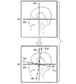
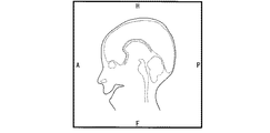
図5は、装置座標系のY−Z平面における頭部断面像を用いた装置座標系の座標軸と、患者座標系の座標軸との傾きの設定操作の一例を示す説明図である。図5(a)は、ユーザによる操作前の断面像の一例を示す模式図であり、図5(b)は、断面像上に重畳表示された患者座標系の座標軸の回転後の状態の一例を示す模式図である。 FIG. 5 is an explanatory diagram illustrating an example of an operation for setting an inclination between the coordinate axis of the apparatus coordinate system and the coordinate axis of the patient coordinate system using the head cross-sectional image in the YZ plane of the apparatus coordinate system. Fig.5 (a) is a schematic diagram which shows an example of the cross-sectional image before operation by a user, FIG.5 (b) is an example of the state after rotation of the coordinate axis of the patient coordinate system superimposed and displayed on the cross-sectional image. It is a schematic diagram which shows.
図5に示す装置座標系のY−Z平面の断面像の場合も、上記同様、ユーザは、入力装置62を介して患者座標系のY軸94y、Z軸94zをそれぞれ、装置座標系のY軸90y、Z軸90zから傾けることができる。ここでも表示制御部74は、装置座標系のY−Z平面上における直交状態を維持したまま、患者座標系のY軸94y、Z軸94zを連動して回転させる。ズレ量設定部72は、この入力に基づいて、装置座標系のY−Z平面上における両座標系のY軸90y、94yの傾き角度θyz(両座標系のZ軸90z、94zの傾き角度でもある)が何°であるかを算出し、記憶する。
In the case of the cross-sectional image of the YZ plane of the apparatus coordinate system shown in FIG. 5, similarly to the above, the user connects the
図6は、3次元で見た場合の装置座標系、患者座標系の各座標軸の傾き角度を示す説明図である。図6において、装置座標系の各座標軸は実線で示し、患者座標系の各座標軸は点線で示す。また、θxは、3次元で見た場合の装置座標系のX軸90xと、患者座標系のX軸94xとの傾き角度である。同様に、θyは、3次元で見た場合の両座標系のY軸90y、94yの傾き角度であり、θzは、3次元で見た場合の両座標系のZ軸90z、94zの傾き角度である。ここで、2次元で見た場合の両座標系の座標軸の各傾き角度θxy、θxz、θyz(図3〜図5参照)は、3次元で見た場合の両座標系の座標軸の各傾き角度θx、θy、θzと同じか、それよりも小さくなる。
FIG. 6 is an explanatory diagram showing inclination angles of the coordinate axes of the apparatus coordinate system and the patient coordinate system when viewed in three dimensions. In FIG. 6, each coordinate axis of the apparatus coordinate system is indicated by a solid line, and each coordinate axis of the patient coordinate system is indicated by a dotted line. Θx is an inclination angle between the
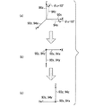
図7は、3次元で見た場合の両座標系の座標軸の各傾き角度と、2次元で見た場合の両座標系の座標軸の各傾き角度の違いを示す説明図である。この例では、図7(a)に示すように、装置座標系のY軸90yを回転軸として10°回転させた3座標軸を患者座標系の各座標軸としている。
FIG. 7 is an explanatory diagram showing the difference between the inclination angles of the coordinate axes of both coordinate systems when viewed in three dimensions and the inclination angles of the coordinate axes of both coordinate systems when viewed in two dimensions. In this example, as shown in FIG. 7A, three coordinate axes rotated by 10 ° with the
3次元で見れば両座標系のX軸90x、94xは互いに10°傾いており、これは、視線方向を装置座標系のY軸90yに合致させて装置座標系のX−Z平面で見れば、識別できる(図示せず)。しかし、図7(b)に示すように、視線方向を装置座標系のZ軸90zに合致させて装置座標系のX−Y平面で見た場合、両座標系のX軸90x、94xの傾きは、分からない。同様に、図7(c)に示すように、視線方向を装置座標系のX軸90xに合致させて装置座標系のY−Z平面で見た場合、両座標系のZ軸90z、94zの傾きは、分からない。
When viewed in three dimensions, the X axes 90x and 94x of both coordinate systems are tilted by 10 ° from each other. This is because the line of sight coincides with the
従って、両座標系の座標軸が上記のように傾いている場合、装置座標系のX−Y平面、Y−Z平面の2断面像においてユーザが前述の傾き角度θxy、θyzを設定しても、装置座標系のX−Z平面における傾き角度θxzは、一義的には決まらない。しかし、装置座標系のX−Z平面、X−Y平面の2断面像でユーザが傾き角度θxz、θxyを設定する場合、装置座標系のY−Z平面の傾き角度θyzは、一義的に決まる。各々の座標系の3座標軸は、互いに直交するからである。従って、装置座標系の直交3平面の任意の2断面像を用い、ユーザの入力に基づいて、両座標系の2次元上の座標軸の傾き角度θxy、θxz、θyzの内の2つを求めた場合、残り1つの傾き角度が一義的に決まるか否かは分からない。 Therefore, when the coordinate axes of both coordinate systems are tilted as described above, even if the user sets the tilt angles θxy and θyz described above in the two cross-sectional images of the XY plane and the YZ plane of the apparatus coordinate system, The inclination angle θxz in the XZ plane of the apparatus coordinate system is not uniquely determined. However, when the user sets the tilt angles θxz and θxy in two cross-sectional images of the XZ plane and the XY plane of the apparatus coordinate system, the tilt angle θyz of the YZ plane of the apparatus coordinate system is uniquely determined. . This is because the three coordinate axes of each coordinate system are orthogonal to each other. Accordingly, two arbitrary cross-sectional images of three orthogonal planes of the apparatus coordinate system are used, and two of the tilt angles θxy, θxz, and θyz of the two-dimensional coordinate axes of both coordinate systems are obtained based on user input. In this case, it is not known whether or not the remaining one inclination angle is uniquely determined.
そこで本実施形態では、装置座標系の直交3平面の任意の2断面像を用い、ユーザの入力に基づいて、両座標系の2次元上の座標軸の傾き角度(θxy、θxz、θyzの内の2つ)を設定する。これにより、残り1つの傾き角度(θxy、θxz、θyzのいずれか)が一義的に決まらない場合、残り1つの断面像を表示させ、ユーザの入力に基づいて残り1つの傾き角度を決定し、そうではない場合、設定済みの2つの傾き角度に基づいて残り1つの傾き角度を決定する。これら傾き角度θxy、θxz、θyzの決定は、ズレ量設定部72により行われる。
Therefore, in this embodiment, two arbitrary cross-sectional images of three orthogonal planes of the apparatus coordinate system are used, and based on the input from the user, the inclination angles (θxy, θxz, θyz) of the coordinate axes on the two-dimensional coordinate axes of both coordinate systems are used. 2) is set. Thus, if the remaining one inclination angle (any of θxy, θxz, θyz) is not uniquely determined, the remaining one cross-sectional image is displayed, and the remaining one inclination angle is determined based on the user input, Otherwise, the remaining one tilt angle is determined based on the two set tilt angles. These inclination angles θxy, θxz, and θyz are determined by the deviation
図8、図9、図10はそれぞれ、撮像画像の表示の第1の例を示す。 8, FIG. 9, and FIG. 10 each show a first example of display of a captured image.
図8は、装置座標系のX−Y平面における頭部断面像の表示例である。図8は、両座標系のX軸90x、94x同士、Y軸90x、94y同士がそれぞれ重なるように、座標軸の交点を中心に、且つ、装置座標系のX−Y平面に平行に傾き角度θxyだけ断面像を回転させたものである。図8に示すように、画像の枠の上辺中央の下には、画像内の被検体Pの領域から離して、体位マークとして「A」を画像に重畳表示する。「A」は、「Anterior」の略であり、患者座標系のY軸方向に沿って被検体Pの前側であることを示す。 FIG. 8 is a display example of a head cross-sectional image in the XY plane of the apparatus coordinate system. FIG. 8 shows an inclination angle θxy centered on the intersection of the coordinate axes and parallel to the XY plane of the apparatus coordinate system so that the X axes 90x and 94x of both coordinate systems overlap each other and the Y axes 90x and 94y overlap each other. Only the cross-sectional image is rotated. As shown in FIG. 8, below the center of the upper side of the frame of the image, “A” is superimposed and displayed on the image as a body posture mark away from the region of the subject P in the image. “A” is an abbreviation for “Anterior” and indicates that it is the front side of the subject P along the Y-axis direction of the patient coordinate system.
同様に、画像の枠の下辺の中央の上側には「P」、右辺の左側には「R」、左辺の右側には「L」を、被検体Pの領域から離して体位マークとして画像に重畳表示する。「P」は、「Posterior」の略であり、患者座標系のY軸方向に沿って被検体Pの後ろ側であることを示す。「R」は、「Right」の略であり、患者座標系のX軸方向に沿って被検体Pの右側であることを示す。「L」は、「Left」の略であり、患者座標系のX軸方向に沿って被検体Pの左側であることを示す。 Similarly, “P” is displayed above the center of the lower side of the frame of the image, “R” is displayed on the left side of the right side, and “L” is displayed on the right side of the left side. Superimposed display. “P” is an abbreviation of “Positioner” and indicates that it is behind the subject P along the Y-axis direction of the patient coordinate system. “R” is an abbreviation of “Right” and indicates that it is on the right side of the subject P along the X-axis direction of the patient coordinate system. “L” is an abbreviation of “Left” and indicates that it is on the left side of the subject P along the X-axis direction of the patient coordinate system.
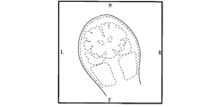
図9は、装置座標系のX−Z平面における頭部断面像の表示例である。図9は、両座標系のX軸90x、94x同士、Z軸90z、94z同士がそれぞれ重なるように、各座標軸の交点を中心に、且つ、装置座標系のX−Z平面に平行に傾き角度θxzだけ断面像を回転させものである。図9に示すように、画像の枠の上辺中央の下側には「H」、下辺中央の上側には「F」、右辺の左側には「R」、左辺の右側には「L」を、被検体Pの領域から離して体位マークとして画像に重畳表示する。「H」は、「Head」の略であり、患者座標系のZ軸方向に沿って被検体Pの頭側であることを示す。「F」は、「Foot」の略であり、患者座標系のZ軸方向に沿って被検体Pの足側であることを示す。体位マーク「R」、「L」については、図8と同様である。 FIG. 9 is a display example of a head cross-sectional image in the XZ plane of the apparatus coordinate system. FIG. 9 shows an inclination angle about the intersection of the coordinate axes and parallel to the XZ plane of the apparatus coordinate system so that the X axes 90x and 94x of both coordinate systems and the Z axes 90z and 94z overlap each other. The sectional image is rotated by θxz. As shown in FIG. 9, “H” is below the center of the upper side of the image frame, “F” is above the center of the bottom side, “R” is on the left side of the right side, and “L” is on the right side of the left side. Then, it is superimposed on the image as a body posture mark away from the region of the subject P. “H” is an abbreviation for “Head”, and indicates the head side of the subject P along the Z-axis direction of the patient coordinate system. “F” is an abbreviation for “Foot”, and indicates that it is on the foot side of the subject P along the Z-axis direction of the patient coordinate system. The posture marks “R” and “L” are the same as those in FIG.
図10は、装置座標系のY−Z平面における頭部断面像の表示例である。図10は、両座標系のY軸90y、94y同士、Z軸90z、94z同士がそれぞれ重なるように、各座標軸の交点を中心に、且つ、装置座標系のY−Z平面に平行に傾き角度θyzだけ断面像を回転させものである。図10に示すように、画像の枠の上辺の中央の下側には「H」、下辺の中央の上側には「F」、右辺の左側には「P」、左辺の右側には「A」を、被検体Pの領域から離して体位マークとして画像に重畳表示する。これら4つの体位マークの意味は、前述と同様である。 FIG. 10 is a display example of a head cross-sectional image in the YZ plane of the apparatus coordinate system. FIG. 10 shows an inclination angle centering on the intersection of each coordinate axis and parallel to the YZ plane of the apparatus coordinate system so that the Y axes 90y and 94y of both coordinate systems and the Z axes 90z and 94z overlap each other. The sectional image is rotated by θyz. As shown in FIG. 10, "H" is below the center of the upper side of the frame of the image, "F" is above the center of the lower side, "P" is on the left side of the right side, and "A" is on the right side of the left side. Is superimposed on the image as a body posture mark away from the region of the subject P. The meanings of these four body position marks are the same as described above.
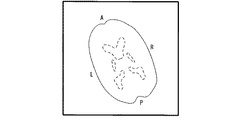
図11は、撮像画像の表示の第2の例を示し、ここでは装置座標系のX−Y平面における頭部断面像を示す。この例では、画像の回転処理を行わない。表示制御部74は、傾き角度θxyで規定される患者座標系のX軸94x、Y軸94yに従って、画像における被検体Pの領域の最も前側の部分のそばに、被検体Pの領域とは重ならないように、体位マーク「A」を画像上に表示させる。同様に、被検体Pの領域の最も後ろ側の部分のそばに「P」を、被検体Pの領域の最も右側の部分のそばに「R」を、被検体Pの領域の最も左側の部分のそばに「L」を、被検体Pの領域とは重ならないように、体位マークとして表示する。装置座標系のX−Z平面、Y−Z平面の2断面像についても、図11と同様の第2の手法で体位マークを表示することができる(図示せず)。
FIG. 11 shows a second example of display of a captured image, and here shows a head cross-sectional image in the XY plane of the apparatus coordinate system. In this example, image rotation processing is not performed. In accordance with the
図12は、撮像画像の表示の第3の例を示し、ここでは装置座標系のX−Y平面における頭部断面像を示す。この例でも、画像の回転処理を行わない。この例では、画像の枠の上辺中央、下辺中央、右辺中央、左辺中央が傾き角度θxyで規定される患者座標系のどの方向に該当するかを判定し、判定した方向を被検体Pの領域とは重ならないように体位マークとして表示する。 FIG. 12 shows a third example of display of a captured image, and here shows a head cross-sectional image in the XY plane of the apparatus coordinate system. Also in this example, image rotation processing is not performed. In this example, it is determined which direction in the patient coordinate system the center of the upper side, the center of the lower side, the center of the right side, and the center of the left side of the image frame are defined by the inclination angle θxy, and the determined direction is the region of the subject P. It is displayed as a posture mark so as not to overlap.
図12内の体位マーク「AR」は、「Anterior」と「Right」の間の方向の意味であり、被検体Pの前側と右側の間の方向を示す。同様に、「AL」は、「Anterior」と「Left」の間の方向の意味であって、被検体Pの前側と左側の間の方向を示し、「PL」は、「Posterior」と「Left」の間の方向の意味であって、被検体Pの後ろ側と左側の間の方向を示し、「PR」は、「Posterior」と「Right」の間の方向の意味であって、被検体Pの後ろ側と右側の間の方向を示す。装置座標系のX−Z平面、Y−Z平面の2断面像についても、図12と同様の第3の手法で体位マークを表示することができる(図示せず)。 The body posture mark “AR” in FIG. 12 means the direction between “Anterior” and “Right”, and indicates the direction between the front side and the right side of the subject P. Similarly, “AL” means the direction between “Anterior” and “Left”, which indicates the direction between the front side and the left side of the subject P, and “PL” is “Posterior” and “Left”. Means the direction between the rear side and the left side of the subject P, and “PR” means the direction between “Posteror” and “Right” The direction between the back side and the right side of P is shown. With respect to the two cross-sectional images of the XZ plane and the YZ plane of the apparatus coordinate system, the posture mark can be displayed by the third method similar to FIG. 12 (not shown).
ここで、図3〜図5は、被検体Pが寝台32上で仰向けに寝ている場合を前提としているため、図3に示す装置座標系のX−Y平面の断面像には、患者座標系のほぼX−Y平面が写されている。従って、装置座標系のX軸90x、Y軸90yと、患者座標系のX軸94x、Y軸94yとの傾き角度θxyを回転操作の入力によって設定できる。図4に示す装置座標系のX−Z平面の断面像、図5に示す装置座標系のY−Z平面の断面像に関しても同様である。
Here, FIGS. 3 to 5 are based on the premise that the subject P is lying on the back on the
即ち、被検体Pが寝台32上で仰向けに寝ている場合、装置座標系の直交3平面の断面像を用いて、回転操作により、両座標系の座標軸の傾き角度θxy、θxz、θyzを設定できる。被検体Pが寝台32上でうつ伏せ(腹臥位)に寝ている場合も同様に、図8〜図10に示す回転操作により、両座標系の各座標軸を2次元画像上で合致させて表示できる。患者座標系のY軸94yにおける正方向と負方向とが入れ替わるだけだからである。
That is, when the subject P is lying on the back on the
一方、被検体Pが寝台32上で右肩下(右側臥位)か、左肩下(左側臥位)に寝ている場合、装置座標系のX−Z平面の断面像では、患者座標系のほぼY−Z平面が写され、装置座標系のY−Z平面の断面像では、患者座標系のほぼX−Z平面が写される。即ち、両座標系の平面が合致しない。
On the other hand, when the subject P is sleeping on the
そこで入力装置62は、座標軸の置換設定用の操作釦群(図示せず)を有する。ユーザは、入力装置62を介して、装置座標系のX−Z平面の断面像上において回転可能に表示される患者座標系のX軸94x、Z軸94zを、患者座標系のY軸94y、Z軸94zに設定変更できる。この後、ユーザは、両座標系のZ軸90z、94zがどれだけ傾いているかを断面像で確認しながら、両座標系のZ軸90z、94z同士が合致するように、患者座標系のY軸94y、Z軸94zを回転させればよい。
Therefore, the
この後、ズレ量設定部72は、入力に基づいて装置座標系のX−Z平面における両座標系のZ軸90z、94zの傾き角度として、θxzが何°であるかを算出し、記憶する。そして、表示制御部74は、図9に示す第1の表示例に従って装置座標系のX−Z平面の断面像を表示する場合、図9と同様にθxzだけ回転後、患者座標系のY−Z平面が写されているものとして、「A」、「P」、「H」等の体位マークを表示させる。装置座標系のX−Y平面、Y−Z平面の各断面像についても同様の操作および画像表示ができるように、入力装置62、表示制御部74は構成される。
Thereafter, the deviation
以下、第1の実施形態のMRI装置20全体の動作を説明するが、ここでは一例として、以下の2グループからなる1スタディの撮像を例に説明する。なお、グループ分け方法については、一例として、投光器34の光を当てた撮像位置の設定を行う毎に、グループを変えるものとする。
Hereinafter, the operation of the
[1]第1グループの撮像(腹部、腎臓検査)
(1)第1シリーズ:腎動脈画像50枚(アキシャル断面像20枚、コロナル断面像10枚、サジタル断面像20枚)
(2)第2シリーズ:腎静脈画像50枚(アキシャル断面像20枚、コロナル断面像10枚、サジタル断面像20枚)
(3)第3シリーズ:T1強調画像50枚(アキシャル断面像20枚、コロナル断面像10枚、サジタル断面像20枚)
(4)第4シリーズ:T2強調画像50枚(アキシャル断面像20枚、コロナル断面像10枚、サジタル断面像20枚)
[1] First group imaging (abdomen, kidney examination)
(1) First series: 50 renal artery images (20 axial sectional images, 10 coronal sectional images, 20 sagittal sectional images)
(2) Second series: 50 renal vein images (20 axial sectional images, 10 coronal sectional images, 20 sagittal sectional images)
(3) Third series: 50 T1-weighted images (20 axial sectional images, 10 coronal sectional images, 20 sagittal sectional images)
(4) Fourth series: 50 T2-weighted images (20 axial sectional images, 10 coronal sectional images, 20 sagittal sectional images)
[2]第2グループの撮像(胸部、肺検査)
(1)第1シリーズ:T1強調画像50枚(アキシャル断面像20枚、コロナル断面像10枚、サジタル断面像20枚)
(2)第2シリーズ:T2強調画像50枚(アキシャル断面像20枚、コロナル断面像10枚、サジタル断面像20枚)
[2] Imaging of the second group (chest and lung examination)
(1) 1st series: 50 T1-weighted images (20 axial sectional images, 10 coronal sectional images, 20 sagittal sectional images)
(2) Second series: 50 T2-weighted images (20 axial sectional images, 10 coronal sectional images, 20 sagittal sectional images)
上記の第1グループは、スライス数が第2グループの2倍であるため、第2グループと対比して撮像期間が長い分、両座標系の座標軸の傾き角度θxy、θxz、θyzが撮像期間中の被検体Pの動きで変動しやすい。そこで、第1の実施形態では一例として、第1グループの第3シリーズの撮像前に、傾き角度θxy、θxz、θyzを再設定する場合について説明する。また、MRI装置20は、装置座標系の各座標軸と患者座標系の各座標軸との各傾き角度の設定について、図3〜図5で説明したようにユーザの入力操作に基づいて行うマニュアルモードと、自動的に設定する自動モードとを有する。
Since the number of slices of the first group is twice that of the second group, the tilt angles θxy, θxz, and θyz of the coordinate axes of both coordinate systems are during the imaging period because the imaging period is longer than the second group. It tends to fluctuate due to the movement of the subject P. Therefore, in the first embodiment, as an example, a case where the tilt angles θxy, θxz, and θyz are reset before imaging of the third series of the first group will be described. In addition, the
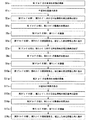
図13は、第1の実施形態のMRI装置20におけるマニュアルモードの動作を示すフローチャートである。以下、適宜図1〜図5、図8〜図12を参照しながら、図13に示すステップ番号に従って、MRI装置20の動作を説明する。
FIG. 13 is a flowchart showing the operation in the manual mode in the
[ステップS1]以下のようにして位置決め画像の画像データが生成される。 [Step S1] Image data of the positioning image is generated as follows.
まず、シーケンスコントローラ50(図1参照)は、演算装置60の指令に従って寝台位置制御装置49を駆動することで、被検体Pが乗せられた寝台32を移動させ、被検体Pの撮像部位(この例では腹部)に投光器34の光が当たるようにする。次に、シーケンスコントローラ50は、演算装置60の指令に従って投光器34を制御し、投光器34の光を被検体Pの撮像部位に当て、撮像部位の位置を設定する。
First, the sequence controller 50 (see FIG. 1) drives the bed
次に、シーケンスコントローラ50は、MRI装置20の設計時に決まるガントリ内の磁場中心と投光器34との距離だけ、寝台32を所定方向に移動させ、被検体Pの撮像部位が磁場中心に置かれるように寝台32を移動させる。このようにして、被検体Pの撮像部位の位置合わせが行われる。
Next, the
次に、MRI装置20は、位置決めの基準に用いる親画像を撮像する(このときの位相エンコードマトリクス数および周波数エンコードマトリクス数は粗めでよい)。これにより、親画像の画像データが生成される。
Next, the
具体的には、MRI装置20は、画像データ収集用のRFパルス等を送信し、被検体PからのMR信号をRF受信器48により検出する。シーケンスコントローラ50は、MR信号の生データを画像再構成部76(図2参照)に入力し、画像再構成部76は、この生データに所定の処理を施して親画像の画像データを生成し、これを画像処理部78に入力する。画像処理部78は、入力された画像データに所定の画像処理を施し、記憶装置66は、画像処理後の親画像の画像データを記憶する。
Specifically, the
次に、MRI装置20は、親画像の画像データに基づいて、装置座標系の直交3平面を含む腹部の位置決め画像を撮像する。これにより、位置決め画像の画像データが生成され、位置決め画像の画像データが記憶装置66に記憶される。
Next, the
[ステップS2]表示制御部74は、MPU70の指令に従って、ステップS1で生成された位置決め画像の画像データを記憶装置66から取得し、位置決め画像を表示装置64上に表示させる。このとき、表示制御部74は、画像の中心を通るように例えば実線で(固定的に)装置座標系の2座標軸を位置決め画像上に重畳表示させると共に、患者座標系の2軸も例えば点線で画像の中心を通るように(回転可能に)重畳表示させる(図3(a)、図4(a)、図5(a)参照)。
[Step S <b> 2] The
[ステップS3]第1グループの第1および第2シリーズの撮像画像に対する被検体Pの体位情報の補正基準として、傾き角度θxy、θxz、θyzを以下のように設定する。 [Step S3] Inclination angles θxy, θxz, and θyz are set as follows as correction standards for the posture information of the subject P with respect to the first and second series of captured images of the first group.
まず、表示制御部74は、装置座標系の直交3平面における各位置決め画像の内の1つを表示装置64上に表示させる。ユーザは、位置決め画像に写っている被検体Pの左右方向、前後方向、または、上下方向に合致するように、患者座標系の2座標軸を入力装置62を介して表示装置64の画面上で回転させる(図3(b)、図4(b)、図5(b)参照)。
First, the
次に、表示制御部74は、装置座標系の直交3平面における各位置決め画像の内の別の1つを表示装置64上に表示させ、ユーザは、同様に患者座標系の2座標軸を表示装置64の画面上で回転させる。
Next, the
ズレ量設定部72は、以上の2回の入力に基づいて、両座標系の2次元上の座標軸の傾き角度θxy、θxz、θyzの内の2つを算出および記憶すると共に、算出された2つの傾き角度に基づいて、残り1つの傾き角度を算出および記憶する。但し、前述したように2つの傾き角度に基づいて残り1つの傾き角度を一義的に決定できない場合、表示制御部74は、装置座標系の直交3平面における各位置決め画像の内の残り1つを表示させる。そして、ズレ量設定部72は、この表示画像に対するユーザの入力に基づいて、残り1つの傾き角度(θxy、θxz、θyzのいずれか)を決定する。
The deviation
なお、ズレ量設定部72は、後述のステップS7、S13においても、それぞれ傾き角度θxy、θxz、θyzを求める。ズレ量設定部72は、ステップS3で算出したθxy、θxz、θyzは第1グループの第1および第2シリーズの撮像画像用として、ステップS7で算出したθxy、θxz、θyzは第1グループの第3および第4シリーズの撮像画像用として、ステップS13で算出したθxy、θxz、θyzは第2グループの撮像画像用として、別々に記憶する。
The deviation
[ステップS4]第1グループの第1および第2シリーズの位置決めが行われる。具体的には、表示制御部74は、装置座標系の直交3平面における各位置決め画像等を表示させ、第1グループの第1および第2シリーズについて、撮像領域をどこにするか等の撮像条件の設定をユーザに促す。ユーザは、表示装置64上の表示に従って、第1グループの第1および第2シリーズの撮像領域等を設定する。
[Step S4] Positioning of the first and second series of the first group is performed. Specifically, the
[ステップS5]MRI装置20は、第1グループの第1および第2シリーズについて撮像を行うことで、各スライスの画像データを生成し、これらを記憶装置66に記憶させる。このとき、記憶装置66は、画像再構成部76により生成され、画像処理部78により画像処理が施された各スライスの画像データに、撮像条件および患者情報を付帯情報として包含させて記憶する。第1の実施形態では一例として、撮像後の各スライスの画像データの付帯情報には、(例えばガントリに対する被検体Pの挿入方向などに基づく)被検体Pの体位情報が含まれるものとする。
[Step S5] The
[ステップS6]画像処理部78は、第1グループの第1および第2シリーズの各画像データに対して、ステップS3で算出された傾き角度θxy、θxz、θyzに基づいて被検体Pの体位方向を正確に求め、各画像データに付随する体位情報を補正する。
[Step S6] The
上記補正の第1の例は、図8〜図10で説明したように、傾き角度θxy、θxz、θyzに基づいて両座標系の座標軸が合致するように(画像の縦方向および横方向が患者座標系の2座標軸に合致するように)画像を回転させ、正確な体位マークを画像の外周部に含ませるものである。上記補正の第2の例は、図11で説明したように、傾き角度θxy、θxz、θyzに基づいて、画像における被検体Pの領域のそばに、正確な体位マーク「A」、「P」、「R」、「L」等を含ませるものである。上記補正の第3の例は、図12で説明したように、傾き角度θxy、θxz、θyzに基づいて、画像の枠の4辺中央のそばに、正確な体位マーク「AL」、「AR」等を含ませものである。 As described with reference to FIGS. 8 to 10, the first example of the correction is that the coordinate axes of both coordinate systems are matched based on the inclination angles θxy, θxz, and θyz (the vertical and horizontal directions of the image are patient The image is rotated (according to the two coordinate axes of the coordinate system), and an accurate posture mark is included in the outer periphery of the image. In the second example of the correction, as described with reference to FIG. 11, based on the inclination angles θxy, θxz, θyz, the correct posture marks “A”, “P” are located near the region of the subject P in the image. , “R”, “L”, and the like. In the third example of the correction, as described with reference to FIG. 12, the correct posture marks “AL” and “AR” are located near the center of the four sides of the image frame based on the inclination angles θxy, θxz, and θyz. Etc. are included.
この後、表示制御部74は、画像処理部78によって体位情報が補正された第1グループの第1および第2シリーズの各画像データが示す画像を、体位マークと共に表示装置64上に表示させる(図8〜図12参照)。
Thereafter, the
[ステップS7]第1グループの第3および第4シリーズの撮像画像に対する被検体Pの体位情報の補正基準として、傾き角度θxy、θxz、θyzをステップS3と同様の手順で設定する。ステップS3との違いは、ユーザによる傾きの設定入力用に表示する画像の違いのみである。 [Step S7] Inclination angles θxy, θxz, and θyz are set in the same procedure as in step S3 as a correction reference for the posture information of the subject P with respect to the captured images of the third and fourth series of the first group. The only difference from step S3 is the difference in the image displayed for the tilt setting input by the user.
即ち、表示制御部74は、ステップS1で撮像した位置決め画像ではなく、第1グループの第2シリーズにおける、なるべく撮像時刻(データ収集期間)が後の撮像画像(装置座標系の直交3平面の各断面像の2種類を含む)を表示装置64上に表示させる。ユーザは、これら表示画像に基づいて患者座標系の座標軸を回転させる。撮像時刻が後の撮像画像を選択する理由は、時間経過に伴う被検体Pの動きによるズレを考慮すれば、直前に撮像された画像を用いた方が体位情報をより正確に補正可能だからである。
That is, the
この後、ズレ量設定部72は、表示画像に対するユーザの2回の入力に基づいて、両座標系の2次元上の座標軸の傾き角度θxy、θxz、θyzの内の2つを算出および記憶する。ズレ量設定部72は、算出された2つの傾き角度に基づいて、残り1つの傾き角度を算出および記憶する。2つの傾き角度に基づいて残り1つの傾き角度を一義的に決定できない場合、ステップS3と同様に、表示制御部74は残り1断面の撮像画像を表示させ、ズレ量設定部72は、この表示画像に対するユーザの回転操作による入力に基づいて、残り1つの傾き角度を決定する。
Thereafter, the deviation
[ステップS8]第1グループの第3および第4シリーズの位置決めが行われる。具体的には、表示制御部74は、第1グループの第2シリーズにおける、なるべく撮像時刻が後の撮像画像(装置座標系の直交3平面の断面像の3種類を含む)を表示させ、撮像領域等の設定をユーザに促す。ユーザは、表示装置64上の表示に従って、第1グループの第3および第4シリーズの撮像領域等を設定する。
[Step S8] Positioning of the third and fourth series of the first group is performed. Specifically, the
[ステップS9]MRI装置20は、第1グループの第3および第4シリーズについて撮像を行うことで、各スライスの画像データを生成し、これらを記憶装置66に記憶させる。
[Step S <b> 9] The
[ステップS10]画像処理部78は、第1グループの第3および第4シリーズの各画像データに対して、ステップS7で算出された傾き角度θxy、θxz、θyzに基づいて被検体Pの体位方向を正確に求め、各画像データに付随する体位情報を補正する。ここでの補正は、ステップS6で3つの例を挙げて説明したものと同様である。この後、表示制御部74は、画像処理部78によって体位情報が補正された第1グループの第3および第4シリーズの各画像データが示す画像を、体位マークと共に表示装置64上に表示させる(図8〜図12参照)。
[Step S10] The
[ステップS11]ステップS1と同様に、第2グループの位置決め画像の画像データが生成される。具体的には、MRI装置20は、寝台32を所定位置に移動させ、被検体Pの撮像部位(この例では胸部)に投光器34の光が当たるようにする。次に、MRI装置20は、投光器34の光を被検体Pの撮像部位に当てて撮像部位の位置を設定後、被検体Pの撮像部位が磁場中心になるように寝台32を移動する。次に、MRI装置20は、位置決めの基準に用いる親画像を撮像し、親画像の画像データを記憶装置66に記憶させる。次に、MRI装置20は、親画像の画像データに基づいて、装置座標系の直交3平面を含む胸部の各位置決め画像を撮像し、各位置決め画像の画像データを記憶装置66に記憶させる。
[Step S11] Similar to step S1, image data of the second group of positioning images is generated. Specifically, the
[ステップS12]表示制御部74は、MPU70の指令に従って、ステップS11で生成された各位置決め画像の画像データを記憶装置66から取得し、各位置決め画像を表示装置64上に表示させる。このときの表示は、ステップS2と同様である。
[Step S12] The
[ステップS13]第2グループの全シリーズの撮像画像に対する被検体Pの体位情報の補正基準として、傾き角度θxy、θxz、θyzをステップS3と同様にして設定(算出)する。 [Step S13] Inclination angles θxy, θxz, and θyz are set (calculated) in the same manner as in step S3 as a correction reference for body posture information of the subject P for all series of captured images of the second group.
[ステップS14]第2グループの位置決めが行われる。具体的には、表示制御部74は、ステップS11で生成した装置座標系の直交3平面の各位置決め画像等を表示させ、第2グループについて、撮像領域をどこにするか等の撮像条件の設定をユーザに促す。ユーザは、表示装置64上の表示に従って、第2グループの撮像領域等を設定する。
[Step S14] Positioning of the second group is performed. Specifically, the
[ステップS15]MRI装置20は、第2グループについて撮像を行うことで、各スライスの画像データを生成し、これらを記憶装置66に記憶させる。
[Step S15] The
[ステップS16]画像処理部78は、第2グループの各画像データに対して、ステップS13で算出された傾き角度θxy、θxz、θyzに基づいて被検体Pの体位方向を正確に求め、各画像データに付随する体位情報を補正する。ここでの補正は、ステップS6と同様である。
[Step S16] The
この後、表示制御部74は、画像処理部78によって体位情報が補正された第2グループの各画像データが示す画像を、体位マークと共に表示装置64上に表示させる(図8〜図12参照)。また、表示制御部74は、ユーザの入力に基づく指令に応じて、画像処理部78によって体位情報が補正された第1グループの各シリーズの各画像データが示す画像も、体位マークと共に表示装置64上に表示させる。
Thereafter, the
以上がマニュアルモードにおけるMRI装置20の動作説明である。
The above is the description of the operation of the
一方、自動モードでは、MRI装置20の動作は、以下に説明するステップS3、S7、S13の動作の一部のみマニュアルモードとは異なり、他の動作はマニュアルモードと同じである。即ち、上記のステップS3、S7、S13では、ユーザの入力を伴わずに、傾き角度θxy、θxz、θyzを各ステップS3、S7、S13毎にそれぞれ自動的に算出し、別々に記憶する。
On the other hand, in the automatic mode, the operation of the
具体的には、まず、画像処理部78は、装置座標系の直交3平面の各断面像の内の2つまたは3つの画像データに対して、ノイズ除去処理を施す。次に、画像処理部78は、ノイズ除去後の画像データに対し閾値処理を施すことで、画像の外縁部の低信号部分(黒い領域)と連結している部分を空気領域とみなした空気マスク像を作成し、空気マスク像の外縁を体表境界線として抽出する。
Specifically, first, the
次に、画像処理部78は、人体の各骨や臓器の形状、大きさ等を含む標準的な人体モデルに基づいて、画像における被検体Pの領域とテンプレートマッチングを行い、被検体Pの各体内組織の領域を抽出する。画像処理部78は、抽出した各体内組織の領域の位置をズレ量設定部72に入力する。
Next, the
次に、ズレ量設定部72は、各体内組織の位置に基づいて、画像における被検体Pの左右方向、前後方向、上下方向を判定する。そして、ズレ量設定部72は、被検体Pの左右方向、前後方向、上下方向をそれぞれ患者座標系のX軸方向、Y軸方向、Z軸方向として定め、装置座標系の直交3平面で見た両座標系の各傾き角度θxy、θxz、θyzを算出する。
Next, the deviation
以上が自動モードにおけるMRI装置20の動作説明である。
The above is the description of the operation of the
以下、第1の実施形態と従来技術との違いについて説明する。 Hereinafter, differences between the first embodiment and the prior art will be described.
図14は、装置座標系のX−Z平面における被検体の頭部断面像および体位マークの従来の表示例を示す。この例は、被検体が、背骨の延在方向をおおよそ装置座標系のZ軸方向に沿って仰向けに寝ている場合を想定したものである。従来のMRI装置の撮像画像につく体位マークは、ガントリへの挿入時の被検体の姿勢に基づき、装置座標系の座標軸に沿って付けられる。装置座標系の座標軸に対して被検体の体位が斜めに傾いていた場合(例えば、被検体の上下方向が装置座標系のZ軸に対して傾いていた場合)においても、図14に示すように、装置座標系のX軸、Z軸に沿って体位マークが表示される。このため、図14に示すように、撮像画像に付帯表示される体位マーク「H」、「F」、「R」、「L」は、被検体の実際の上下方向、左右方向とはずれてしまう。 FIG. 14 shows a conventional display example of the head cross-sectional image of the subject and the body position mark in the XZ plane of the apparatus coordinate system. In this example, it is assumed that the subject is lying on his back with the extending direction of the spine approximately along the Z-axis direction of the apparatus coordinate system. A posture mark attached to a captured image of a conventional MRI apparatus is attached along the coordinate axis of the apparatus coordinate system based on the posture of the subject at the time of insertion into the gantry. As shown in FIG. 14, even when the posture of the subject is inclined with respect to the coordinate axis of the apparatus coordinate system (for example, when the vertical direction of the subject is inclined with respect to the Z axis of the apparatus coordinate system). The posture mark is displayed along the X-axis and Z-axis of the apparatus coordinate system. For this reason, as shown in FIG. 14, the body posture marks “H”, “F”, “R”, and “L” that are incidentally displayed on the captured image deviate from the actual vertical and horizontal directions of the subject. .
一方、第1の実施形態では、両座標系の傾き角度θxy、θxz、θyzを算出し(ステップS3、S7、S13)、これに基づいて被検体Pの体位情報を補正して、正確な体位マークを撮像画像と共に表示する(ステップS6、S10、S16)。このため、患者が寝台32上で寝台32の長手方向(装置座標系のZ軸方向)などの所定方向に平行に寝ることができない場合にも、撮像画像上に正確な体位マークを表示できる。この結果、診断がしやすくなる。換言すれば、患者も寝台32上で所定方向に沿って寝なくてもよいので、患者の負担も軽減する。
On the other hand, in the first embodiment, the inclination angles θxy, θxz, θyz of both coordinate systems are calculated (steps S3, S7, S13), and based on this, the posture information of the subject P is corrected to obtain an accurate posture. The mark is displayed together with the captured image (steps S6, S10, S16). For this reason, even when the patient cannot sleep on the
マニュアルモードでは、ユーザは、ステップS3で両座標系の傾きを1回設定するだけで、第1グループの第1および第2シリーズの全撮像画像(この例では100スライス)の画像データに対し、上記のように正確な体位情報を包含させることができる。第1グループの第3および第4シリーズ、第2グループに関しても同様である(ステップS7、S13)。このため、多数の撮像を行う場合に、ユーザに大きな操作負担を与えることなく、撮像画像に付随する体位情報を従来よりも正確にすることができる。 In the manual mode, the user only sets the inclination of both coordinate systems once in step S3, and the image data of all the first series of first and second series captured images (100 slices in this example) As described above, accurate posture information can be included. The same applies to the third and fourth series and the second group of the first group (steps S7 and S13). For this reason, when performing many imaging, the posture information accompanying a captured image can be made more accurate than before without imposing a heavy operation burden on the user.
さらに、自動モードでは、ユーザの入力を伴わずに両座標系の傾き角度θxy、θxz、θyzを自動的に算出し、全撮像画像の画像データに付随する体位情報を正確に補正する。従って、自動モードでは、多数の撮像を行う場合に、ユーザに殆ど操作負担を与えることなく、撮像画像に付随する体位情報を従来よりも正確にすることができる。 Further, in the automatic mode, the tilt angles θxy, θxz, θyz of both coordinate systems are automatically calculated without any user input, and the posture information associated with the image data of all captured images is accurately corrected. Therefore, in the automatic mode, when a large number of images are captured, the posture information associated with the captured image can be made more accurate than before, with little operational burden on the user.
また、傾き角度θxy、θxz、θyzを再設定後に撮像した画像データに対しては、再設定した傾き角度θxy、θxz、θyzに基づいて体位マークを表示し、再設定前の傾き角度θxy、θxz、θyzは体位マークの補正に用いない。即ち、第1グループの第1および第2シリーズ、第1グループの第3および第4シリーズ、第2グループ、と別々に傾き角度θxy、θxz、θyzを設定し、別々に体位情報を補正するので、1スタディの撮像期間中の被検体Pの動きがあっても、より正確に体位情報を補正できる。 For image data captured after resetting the tilt angles θxy, θxz, and θyz, a posture mark is displayed based on the reset tilt angles θxy, θxz, θyz, and the tilt angles θxy, θxz before resetting , Θyz are not used for correcting the posture mark. That is, since the tilt angles θxy, θxz, θyz are set separately for the first and second series of the first group, the third and fourth series of the first group, and the second group, and the posture information is corrected separately. Even if the subject P moves during the imaging period of one study, the posture information can be corrected more accurately.
また、第1の実施形態では、少なくともグループ毎に傾き角度θxy、θxz、θyzを別々に設定して、体位情報を別々に補正する。従って、グループ毎に撮像部位を変えれば(第1の実施形態では腹部と胸部)、撮像部位毎に体位情報を補正できる。この結果、患者が体を曲げて寝ることしかできないような場合にも、ある程度正確に体位マークを表示できる。 In the first embodiment, the inclination angle θxy, θxz, θyz is set separately for each group, and the posture information is corrected separately. Therefore, if the imaging region is changed for each group (in the first embodiment, the abdomen and the chest), the body position information can be corrected for each imaging region. As a result, even when the patient can only sleep with his body bent, the body position mark can be displayed with a certain degree of accuracy.
<第2の実施形態>
第2の実施形態のMRI装置は、ハードウェア的な構成としては第1の実施形態と同様であるので、第1の実施形態と符号を同じくMRI装置20として表記する。第2の実施形態のMRI装置20では、自動モードの動作は第1の実施形態と同様なので説明を省略するが、マニュアルモードにおける動作が以下の2点のみ異なる。
<Second Embodiment>
Since the MRI apparatus of the second embodiment is the same as that of the first embodiment in terms of hardware configuration, the same reference numerals as those in the first embodiment are used as the
第1に、ユーザは、入力により体位情報の補正設定を解除できる。なお、第2の実施形態では一例として、以下の3つの場合を除いて、一度補正設定された体位情報は保持されて、その後の撮像画像の体位情報の補正に継続的に用いられるものとする。3つの場合とは、(1)ユーザの入力により解除される場合、(2)ユーザの入力により再設定される場合、(3)撮像条件としての被検体Pの体位を変える場合である。「撮像条件としての被検体Pの体位を変える」とは、具体的には、ガントリ内から寝台32を出し、被検体Pの体位を変えて位置決め等を再度行うことである。
First, the user can cancel the correction setting of the posture information by input. In the second embodiment, as an example, except for the following three cases, the posture information once corrected and set is retained and continuously used for correcting the posture information of the subsequent captured image. . The three cases are (1) cancellation by user input, (2) resetting by user input, and (3) changing the posture of the subject P as imaging conditions. Specifically, “changing the posture of the subject P as an imaging condition” means that the
第2に、体位情報の補正設定の解除指示があった場合、解除指示の後に行われる撮像によって生成される画像データに対しては、体位情報の補正を行わずに、補正されていない体位情報を画像として表示する。 Secondly, when there is an instruction to cancel the correction setting of the body position information, the body position information is not corrected without correcting the body position information for image data generated by imaging performed after the cancellation instruction. Is displayed as an image.
図15は、第2の実施形態のMRI装置20におけるマニュアルモードの動作を示すフローチャートである。以下、適宜図1〜図5、図8〜図12、図14を参照しながら、図15に示すステップ番号に従って、第2の実施形態のMRI装置20の動作を説明する。なお、第2の実施形態においても、第1の実施形態と同じ構成の1スタディの撮像を例として説明する。
FIG. 15 is a flowchart showing the operation in the manual mode in the
[ステップS1a、S2a]第1の実施形態のステップS1、S2と同様に位置決め画像の画像データが生成され、表示制御部74は、位置決め画像の画像データを記憶装置66から取得し、位置決め画像を表示装置64上に表示させる。
[Steps S1a, S2a] The image data of the positioning image is generated in the same manner as in steps S1, S2 of the first embodiment, and the
[ステップS3a]第1グループの第1および第2シリーズの撮像画像に対する被検体Pの体位情報の補正基準として、第1の実施形態のステップS3と同様に両座標系の座標軸の傾きが入力され、傾き角度θxy、θxz、θyzがズレ量設定部72によって算出および記憶される。なお、第2の実施形態では、体位情報の補正基準として傾き角度を設定するステップS3a、S7a、S13aにおいて、ユーザは、体位情報の補正設定を解除できる。ここでは一例として、このステップS3aでは、第1の実施形態と同様に傾き角度θxy、θxz、θyzが算出および記憶されるものとする。
[Step S3a] As the correction reference for the posture information of the subject P with respect to the first and second series of captured images of the first group, the inclinations of the coordinate axes of both coordinate systems are input as in Step S3 of the first embodiment. The inclination angles θxy, θxz, θyz are calculated and stored by the deviation
[ステップS4a、S5a、S6a]第1の実施形態のステップS4、S5、S6と同様の処理が行われる。即ち、第1グループの第1および第2シリーズの撮像領域等が設定され(ステップS4a)、第1グループの第1および第2シリーズの撮像が行われる(ステップS5a)。この後、第1グループの第1および第2シリーズの各画像データが示す画像が、補正された体位情報(体位マーク)と共に表示される(ステップS6a)。 [Steps S4a, S5a, S6a] The same processes as in steps S4, S5, S6 of the first embodiment are performed. That is, the first and second series imaging areas of the first group are set (step S4a), and the first and second series imaging of the first group are performed (step S5a). Thereafter, the images represented by the first and second series of image data of the first group are displayed together with the corrected body posture information (body posture mark) (step S6a).
[ステップS7a]体位情報の補正基準として傾き角度を設定するための画像が表示装置64上に表示される。ここで、ユーザには、3つの選択肢がある。
[Step S7a] An image for setting an inclination angle as a correction reference for body posture information is displayed on the
第1の選択肢は、ユーザが体位情報の補正設定の解除を行わず、且つ、ユーザが体位情報の再設定も行わない場合である。即ち、ステップS3aで設定され、ズレ量設定部72によって保持されている体位情報を用いる場合である。この場合、第1グループの第3および第4シリーズの撮像画像も、第1グループの第1および第2シリーズの撮像画像と同様に、ステップS3aで設定された傾き角度によって体位情報が補正される。
The first option is a case where the user does not cancel the correction setting of the posture information and the user does not reset the posture information. That is, the posture information set in step S3a and held by the deviation
第2の選択肢は、ユーザが表示装置64上に表示される画像を用いて体位情報を再設定する、即ち、両座標系の座標軸の傾きを入力する場合である。この場合は、第1の実施形態と同様になる。
The second option is a case where the user resets the body position information using an image displayed on the
第3の選択肢は、ステップS3aで設定され、ズレ量設定部72によって保持されている体位情報を、ユーザが入力により解除する場合である。第2の実施形態では一例として、ユーザはステップS7aにおいて、この第3の選択肢を採るものとする。この場合、入力装置62からズレ量設定部72に体位情報の補正設定の解除指示が入力され、ズレ量設定部72は、第1グループの第3および第4シリーズには傾き角度を設定しない。
The third option is a case where the user releases the posture information set in step S3a and held by the deviation
[ステップS8a、S9a]第1の実施形態のステップS8、S9と同様に、第1グループの第3および第4シリーズの位置決めおよび撮像が行われ、各スライスの画像データが記憶装置66に記憶される。
[Steps S8a, S9a] Similar to steps S8, S9 of the first embodiment, the third and fourth series of the first group are positioned and imaged, and the image data of each slice is stored in the
[ステップS10a]画像処理部78は、第1グループの第3および第4シリーズの各画像データに対して、体位情報の補正を行わない。即ち、第1グループの第3および第4シリーズの各画像データには、従来と同様の装置座標系の座標軸のみに基づく体位情報が付帯情報として含まれる。この後、表示制御部74は、第1グループの第3および第4シリーズの各画像データが示す画像を、補正されていない体位マークと共に表示装置64上に表示させる(例えば図14参照)。
[Step S10a] The
[ステップS11a、12a]第1の実施形態のステップS11、12と同様に、第2グループの位置決め画像の画像データが生成され、表示制御部74は、位置決め画像を表示装置64上に表示させる。
[Steps S11a, 12a] As in Steps S11, S12 of the first embodiment, image data of the second group of positioning images is generated, and the
[ステップS13a]先のステップS7aで体位情報の補正設定が解除されているので、ステップS7aで述べた第1の選択肢はないが、ユーザは以下の2つの選択肢のいずれかを採ることができる。第1の選択肢は、ステップS7aで体位情報の補正設定が解除された状態を維持しておく場合、即ち、第2グループの撮像画像に対して体位情報の補正を行わない場合である。第2の選択肢は、第2グループの撮像画像に対する体位情報の補正基準として、両座標系の座標軸の傾きを入力する場合である。ここでは一例として、第2の選択肢が採られ、第1の実施形態のステップS13と同様に、第2グループの撮像画像に対する両座標系の座標軸の傾きが入力され、傾き角度θxy、θxz、θyzが算出、記憶されるものとする。 [Step S13a] Since the correction setting of the posture information is canceled in the previous step S7a, there is no first option described in step S7a, but the user can take one of the following two options. The first option is the case where the posture information correction setting is canceled in step S7a, that is, the case where the posture information is not corrected for the second group of captured images. The second option is a case where the inclination of the coordinate axes of both coordinate systems is input as a correction reference for body posture information with respect to the captured images of the second group. Here, as an example, the second option is taken, and as in step S13 of the first embodiment, the inclinations of the coordinate axes of both coordinate systems with respect to the captured images of the second group are input, and the inclination angles θxy, θxz, θyz are input. Is calculated and stored.
[ステップS14a、15a]第1の実施形態のステップS14、15と同様に、第2グループの位置決めおよび撮像が行われ、第2グループの全スライスの画像データが記憶装置66に記憶される。
[Steps S14a, 15a] As in Steps S14, 15 of the first embodiment, positioning and imaging of the second group are performed, and image data of all slices of the second group is stored in the
[ステップS16a]第1の実施形態のステップS16と同様に、第2グループの各画像データに付随する体位情報がステップS13aで設定された傾き角度に基づいて補正され、第2グループの各画像データが示す画像が、補正された体位マークと共に表示装置64上に表示される。また、表示制御部74は、ユーザの入力に基づく指令に応じて、体位情報が補正された第1グループの第1および第2シリーズの各画像データが示す画像も、表示装置64上に表示させる。また、表示制御部74は、ユーザの入力に基づく指令に応じて、体位情報が補正されていない第1グループの第3および第4シリーズの各画像データが示す画像も、表示装置64上に表示させる。
[Step S16a] Similar to step S16 of the first embodiment, the posture information associated with each image data of the second group is corrected based on the tilt angle set in step S13a, and each image data of the second group is corrected. Is displayed on the
なお、仮に、ステップS16aの後に例えばプロトン密度画像などが撮像条件としての被検体Pの体位を変えずに追加的に撮像される場合、本実施形態の冒頭で述べた3つの場合を除き、ステップS13aで設定された体位情報によって、ステップS16aの後に撮像される画像の体位情報が補正される。 If, for example, a proton density image is additionally imaged without changing the posture of the subject P as an imaging condition after step S16a, the steps except for the three cases described at the beginning of the present embodiment. The posture information of the image captured after step S16a is corrected by the posture information set in S13a.
以上が第2の実施形態のマニュアルモードにおけるMRI装置20の動作説明である。
The above is the description of the operation of the
このように第2の実施形態においても、第1の実施形態と同様の効果を得ることができる。また、撮像目的によっては、被検体Pの体位に基づく正確な体位情報よりも、装置座標系の座標軸のみに基づく体位マークを撮像画像上に付帯表示させたい場合も考えられる。そのような場合に、第2の実施形態では、ユーザは、例えばシリーズによって体位情報の補正を行わないことも選択できるので、体位マークの表示方法の選択の幅が広がる。 Thus, also in 2nd Embodiment, the effect similar to 1st Embodiment can be acquired. Further, depending on the purpose of imaging, there may be a case where a body posture mark based only on the coordinate axes of the apparatus coordinate system is desired to be additionally displayed on the captured image rather than accurate body posture information based on the body posture of the subject P. In such a case, in the second embodiment, the user can select not to correct the posture information by, for example, a series, so that the selection method of the display method of the posture mark is widened.
<本発明の補足事項>
[1]装置座標系の原点と、患者座標系の原点とを一致させ、装置座標系の座標軸と患者座標系の座標軸との傾き角度を回転処理によって補正する例を述べた。本発明は、かかる実施形態に限定されるものではない。装置座標系の原点位置に関係なく、例えば撮像画像上の被検体Pの領域の中心位置に基づいて患者座標系の原点位置を設定してもよい。即ち、平行移動処理によって患者座標系の原点を装置座標系の原点からずらす補正を行うと共に、装置座標系の各座標軸と、患者座標系の各座標軸との傾き角度を上述した回転処理によって補正する構成としてもよい。
<Supplementary items of the present invention>
[1] The example in which the origin of the apparatus coordinate system and the origin of the patient coordinate system are made coincident and the tilt angle between the coordinate axis of the apparatus coordinate system and the coordinate axis of the patient coordinate system is corrected by the rotation process has been described. The present invention is not limited to such an embodiment. Regardless of the origin position of the apparatus coordinate system, the origin position of the patient coordinate system may be set based on the center position of the region of the subject P on the captured image, for example. That is, correction is performed by shifting the origin of the patient coordinate system from the origin of the apparatus coordinate system by the parallel movement process, and the inclination angle between each coordinate axis of the apparatus coordinate system and each coordinate axis of the patient coordinate system is corrected by the above-described rotation process. It is good also as a structure.
[2]第1および第2の実施形態では、人体座標系と装置座標系とのズレ量として、患者座標系(人体座標系の一例)の座標軸と、装置座標系の座標軸との傾き角度を設定する例を述べた。「ズレ量」については、傾き角度に限定されるものではない。例えば、患者座標系の規定方法をズレ量としてズレ量設定部72が設定する構成としてもよい。
[2] In the first and second embodiments, as the amount of deviation between the human body coordinate system and the apparatus coordinate system, the inclination angle between the coordinate axis of the patient coordinate system (an example of the human body coordinate system) and the coordinate axis of the apparatus coordinate system is An example of setting was described. The “deviation amount” is not limited to the tilt angle. For example, it is good also as a structure which the deviation
具体的には例えば、患者座標系の4つの座標点(0、0、0)、(1、0、0)、(0、1、0)、(0、0、1)が、装置座標系ではそれぞれ如何なる座標点として表されるかの座標位置情報をズレ量設定部72が設定する構成としてもよい。ここで、上記の座標点(0、0、0)は患者座標系の原点であり、(1、0、0)、(0、1、0)、(0、0、1)はそれぞれ、患者座標系のX軸、Y軸、Z軸上の座標点である。
Specifically, for example, four coordinate points (0, 0, 0), (1, 0, 0), (0, 1, 0), (0, 0, 1) of the patient coordinate system are represented by the apparatus coordinate system. Then, it is good also as a structure which the deviation
[3]患者座標系の座標軸と、装置座標系の座標軸との傾き角度について、第1の実施形態のステップS3では位置決め画像に基づいて補正する例を述べ、第1の実施形態のステップS7では直前のシリーズの撮像画像に基づいて補正する例を述べた。両座標系の座標軸の傾き角度などの「人体座標系と装置座標系とのズレ量」の設定に用いる画像は、それらに限定されるものではなく、例えば、親画像に基づいて設定する構成としてもよい。 [3] An example in which the tilt angle between the coordinate axis of the patient coordinate system and the coordinate axis of the apparatus coordinate system is corrected based on the positioning image in step S3 of the first embodiment will be described. In step S7 of the first embodiment, An example in which correction is performed based on the captured image of the immediately preceding series has been described. The image used for setting the “deviation amount between the human body coordinate system and the apparatus coordinate system” such as the tilt angle of the coordinate axes of both coordinate systems is not limited to them. For example, the image is set based on the parent image. Also good.
[4]第1の実施形態では、第1グループの撮像において、第1および第2シリーズと、第3および第4シリーズとに分けて、傾き角度の設定を2回行う例を述べたが、第1〜第4シリーズを通してステップS3で設定された傾き角度を用いてもよい。即ち、グループ毎に傾き角度を設定してもよい。或いは、1シリーズの撮像毎に傾き角度を再設定してもよい。ここで、投光器34の光を当てた撮像位置の設定を行う毎にグループを変えるため、グループ毎に、(磁場中心に置かれる)装置座標系の原点が若干ずれる。従って、傾き角度については、少なくともグループ毎に再設定することが望ましい。
[4] In the first embodiment, in the first group of imaging, the example in which the tilt angle is set twice in the first and second series and the third and fourth series is described. The tilt angle set in step S3 through the first to fourth series may be used. That is, the tilt angle may be set for each group. Alternatively, the tilt angle may be reset for each series of imaging. Here, since the group is changed every time the imaging position to which light from the
[5]第1および第2の実施形態では、ステップS5、S9、S15、S5a、S9a、S15aで生成される撮像後の画像データに被検体Pの体位情報が付随しているものとして、体位情報を傾き角度に基づいて補正する例を述べた。撮像後の画像データに体位情報が付随しない場合、傾き角度θxy、θxz、θyzに基づいて、画像処理部78が第1および第2の実施形態と同様の正確な体位情報を生成し、この体位情報を撮像後の画像データに付随させればよい。
[5] In the first and second embodiments, it is assumed that the posture information of the subject P is attached to the image data after imaging generated in steps S5, S9, S15, S5a, S9a, and S15a. An example has been described in which information is corrected based on an inclination angle. When the posture information is not attached to the image data after imaging, the
[6]第1および第2の実施形態では、位置決め画像などの既に行われた撮像動作で生成された画像データおよび入力情報に応じて、その後の撮像動作で生成される予定の画像データにおける患者座標系と装置座標系とのズレ量を予め設定する例を述べた。本発明は、かかる実施形態に限定されるものではない。例えば、選択された画像データを用いて患者座標系と前記装置座標系とのズレ量を設定し、このズレ量によって、当該選択された画像データの体位情報、および、当該選択された画像データよりも撮像時刻が先の画像データの体位情報を補正してもよい。この点について、第1の実施形態の第1グループの第1および第2シリーズの撮像のみが行われる場合を例に、動作フローを簡単に説明する。 [6] In the first and second embodiments, the patient in the image data scheduled to be generated in the subsequent imaging operation according to the image data generated in the already performed imaging operation such as the positioning image and the input information An example in which the amount of deviation between the coordinate system and the apparatus coordinate system is set in advance has been described. The present invention is not limited to such an embodiment. For example, by using the selected image data, a deviation amount between the patient coordinate system and the device coordinate system is set, and the position information of the selected image data and the selected image data are determined based on the deviation amount. Alternatively, the posture information of the image data whose imaging time is earlier may be corrected. With respect to this point, the operation flow will be briefly described by taking as an example the case where only the first and second series imaging of the first group of the first embodiment is performed.
図16は、この変形例におけるMRI装置20の動作を示すフローチャートである。以下、図16に示すステップ番号に従って、この場合のMRI装置20の動作を説明する。
FIG. 16 is a flowchart showing the operation of the
まず、ステップS31では、第1の実施形態のステップS1と同様に、位置決め画像の画像データが生成される。 First, in step S31, image data of a positioning image is generated as in step S1 of the first embodiment.
次に、ステップS32では、第1の実施形態のステップS4と同様に、表示制御部74は、装置座標系の直交3平面における各位置決め画像等を表示させ、ユーザは、撮像領域等を設定する。
Next, in step S32, as in step S4 of the first embodiment, the
次に、ステップS33では、MRI装置20は、第1の実施形態のステップS5と同様に第1グループの第1および第2シリーズについて撮像を行うことで、この例では全100スライス分の画像データを生成し、これらを記憶装置66に記憶させる。
Next, in step S33, the
次に、ステップS34では、ユーザは、入力装置62を介して、第1グループの第1および第2シリーズの全撮像画像の中から、体位情報の補正に用いる画像を選択する。この選択は、アキシャル断面像、コロナル断面像、サジタル断面像の内の2つについて、1つずつ選択される。ここでの選択は、例えば、関心領域を最も多く含む画像が選択され、撮像時刻が最も後の画像が選択される場合もありうる。
Next, in step S <b> 34, the user selects an image to be used for correcting body posture information from all the first and second series captured images of the first group via the
次に、ステップS35では、ステップS34で選択された2画像に基づいて、第1の実施形態のステップS3と同様に、傾き角度θxy、θxz、θyzが設定される。具体的には、ズレ量設定部72は、2画像に対するユーザの回転操作による入力に基づいて、両座標系の座標軸の傾き角度θxy、θxz、θyzの内の2つを算出および記憶すると共に、算出された2つの傾き角度に基づいて、残り1つの傾き角度を算出および記憶する。但し、残り1つの傾き角度を一義的に決定できない場合、表示装置64上には、アキシャル断面像、コロナル断面像、サジタル断面像の内のステップS34で選択されなかった断面像の選択を促す表示がされる。ユーザは、これに基づき、第1グループの第1および第2シリーズの撮像画像から1画像を選択する。そして、ズレ量設定部72は、この画像に対するユーザの入力に基づいて、残り1つの傾き角度を決定する。
Next, in step S35, inclination angles θxy, θxz, and θyz are set based on the two images selected in step S34, as in step S3 of the first embodiment. Specifically, the deviation
次に、ステップS36では、第1の実施形態のステップS6と同様に、体位情報の補正と、補正した体位情報に基づく撮像画像の表示が行われる。即ち、画像処理部78は、全画像データに対して、ステップS35で算出された傾き角度θxy、θxz、θyzに基づいて被検体Pの体位方向を正確に求め、体位情報を補正する。この後、表示制御部74は体位情報が補正された第1グループの第1および第2シリーズの各画像データが示す画像を、体位マークと共に表示装置64上に表示させる。以上が図16にかかる動作説明であり、この場合、ステップS34で選択された画像データを用いて、この選択された画像データよりも撮像時刻が先の画像データの体位情報が補正されうる。
Next, in step S36, as in step S6 of the first embodiment, correction of body position information and display of a captured image based on the corrected body position information are performed. That is, the
[7]被検体Pの体位情報を補正して表示する本発明の技術は、MRI装置に限らず、X線CT装置(X−ray Computed Tomography Apparatus)などの他の医用画像診断装置にも適用可能である。同様に、両座標系の座標軸の傾きに基づいて被検体Pの正確な体位情報を生成し、これを撮像後の画像データに付随させる本発明の技術は、MRI装置に限らず、X線CT装置などの他の医用画像診断装置にも適用可能である。 [7] The technique of the present invention that corrects and displays the body posture information of the subject P is not limited to the MRI apparatus, and is also applied to other medical image diagnostic apparatuses such as an X-ray CT (X-ray Computed Tomography Apparatus). Is possible. Similarly, the technique of the present invention that generates accurate body position information of the subject P based on the inclination of the coordinate axes of both coordinate systems and attaches this information to the image data after imaging is not limited to the MRI apparatus, but the X-ray CT. The present invention can also be applied to other medical image diagnostic apparatuses such as apparatuses.
[8]最後に、請求項の用語と実施形態との対応関係を説明する。なお、以下に示す対応関係は、参考のために示した一解釈であり、本発明を限定するものではない。 [8] Finally, the correspondence between the terms of the claims and the embodiments will be described. In addition, the correspondence shown below is one interpretation shown for reference, and does not limit the present invention.
患者座標系は、請求項記載の人体座標系の一例である。 The patient coordinate system is an example of a human body coordinate system described in the claims.
傾き角度θxy、θxz、θyzに基づいて、画像データに付随する被検体Pの体位方向を補正する画像処理部78の機能は、請求項記載の体位情報設定部の一例である。
The function of the
マニュアルモードにおいて、回転操作によって入力される両座標系の座標軸の傾きは、請求項記載の入力情報の一例である。 In the manual mode, the inclination of the coordinate axes of both coordinate systems input by the rotation operation is an example of input information described in claims.
全自動モードにおいて、画像処理部78により抽出され、ズレ量設定部72に入力される画像データ内の被検体Pの各体内組織の領域の位置は、請求項記載の入力情報の一例である。
In the fully automatic mode, the position of each body tissue region of the subject P in the image data extracted by the
1シリーズの撮像は、請求項記載の撮像シーケンスの一例であり、1グループの撮像も、請求項記載の撮像シーケンスの一例である。 One series of imaging is an example of an imaging sequence described in claims, and one group of imaging is also an example of an imaging sequence described in claims.
表示制御部74および表示装置64は、請求項記載の表示部の一例である。
The
20 MRI装置
22 静磁場用磁石
24 シムコイル
26 傾斜磁場コイル
26x X軸傾斜磁場コイル
26y Y軸傾斜磁場コイル
26z Z軸傾斜磁場コイル
28 RFコイル
30 制御系
32 寝台
34 投光器
40 静磁場電源
42 シムコイル電源
44 傾斜磁場電源
44x X軸傾斜磁場電源
44y Y軸傾斜磁場電源
44z Z軸傾斜磁場電源
46 RF送信器
48 RF受信器
49 寝台位置制御装置
50 シーケンスコントローラ
52 コンピュータ
60 演算装置
62 記憶装置
64 表示装置
66 入力装置
70 MPU
72 ズレ量設定部
74 表示制御部
76 画像再構成部
78 画像処理部
80 システムバス
90x 装置座標系のX軸
90y 装置座標系のY軸
90z 装置座標系のZ軸
94x 患者座標系のX軸
94y 患者座標系のY軸
94z 患者座標系のZ軸
20
72 Displacement
Claims (10)
先に行われた前記撮像動作で生成された前記画像データおよび入力情報に応じて、後に行われる前記撮像動作で生成される前記画像データにおける、前記被検体の体位に基づく人体座標系と前記装置座標系とのズレ量を設定するズレ量設定部と、
前記ズレ量が設定された前記画像データに付随する前記被検体の体位情報を前記ズレ量に基づいて補正する体位情報設定部と
を備えたことを特徴とする磁気共鳴イメージング装置。 A magnetic resonance imaging apparatus that generates a plurality of image data respectively corresponding to each of the imaging operations by performing an imaging operation as magnetic resonance imaging based on the apparatus coordinate system a plurality of times on a subject.
The human body coordinate system and the apparatus based on the posture of the subject in the image data generated by the imaging operation performed later according to the image data and input information generated by the imaging operation performed previously A deviation amount setting unit for setting a deviation amount from the coordinate system;
A magnetic resonance imaging apparatus comprising: a posture information setting unit that corrects the posture information of the subject associated with the image data in which the displacement amount is set based on the displacement amount.
選択された前記画像データおよび入力情報に応じて、この選択された前記画像データとは別の前記画像データにおける、前記被検体の体位に基づく人体座標系と前記装置座標系とのズレ量を設定するズレ量設定部と、
前記ズレ量が設定された前記画像データに付随する前記被検体の体位情報を前記ズレ量に基づいて補正する体位情報設定部と
を備えたことを特徴とする磁気共鳴イメージング装置。 A magnetic resonance imaging apparatus that generates a plurality of image data respectively corresponding to each of the imaging operations by performing an imaging operation as magnetic resonance imaging based on the apparatus coordinate system a plurality of times on a subject.
In accordance with the selected image data and input information, a deviation amount between the human body coordinate system based on the posture of the subject and the apparatus coordinate system in the image data different from the selected image data is set. A deviation amount setting section,
A magnetic resonance imaging apparatus comprising: a posture information setting unit that corrects the posture information of the subject associated with the image data in which the displacement amount is set based on the displacement amount.
前記解除指示の後に行われた前記撮像動作で生成された前記画像データが示す画像と共に、前記体位情報設定部による補正が行われていない前記体位情報を表示する表示部をさらに備える請求項1記載の磁気共鳴イメージング装置。 The deviation amount setting unit is configured not to set the deviation amount with respect to the image data generated by the imaging operation performed after the cancellation instruction when receiving an instruction to cancel the setting of the deviation amount. ,
The display unit for displaying the posture information not corrected by the posture information setting unit together with an image indicated by the image data generated by the imaging operation performed after the release instruction. Magnetic resonance imaging equipment.
選択された前記画像データおよび入力情報に応じて、この選択された前記画像データとは別の前記画像データにおける、前記被検体の体位に基づく人体座標系と前記装置座標系とのズレ量を設定するズレ量設定部と、
前記ズレ量に基づいて前記被検体の体位情報を生成し、前記ズレ量が設定された前記画像データに前記体位情報を付随させる体位情報設定部と
を備えたことを特徴とする磁気共鳴イメージング装置。 A magnetic resonance imaging apparatus that generates a plurality of image data respectively corresponding to each of the imaging operations by performing an imaging operation as magnetic resonance imaging based on the apparatus coordinate system a plurality of times on a subject.
In accordance with the selected image data and input information, a deviation amount between the human body coordinate system based on the posture of the subject and the apparatus coordinate system in the image data different from the selected image data is set. A deviation amount setting section,
A magnetic resonance imaging apparatus comprising: a body position information setting unit that generates body position information of the subject based on the displacement amount, and associates the body position information with the image data in which the displacement amount is set. .
Priority Applications (1)
| Application Number | Priority Date | Filing Date | Title |
|---|---|---|---|
| JP2010053681A JP5481237B2 (en) | 2010-03-10 | 2010-03-10 | Magnetic resonance imaging system |
Applications Claiming Priority (1)
| Application Number | Priority Date | Filing Date | Title |
|---|---|---|---|
| JP2010053681A JP5481237B2 (en) | 2010-03-10 | 2010-03-10 | Magnetic resonance imaging system |
Publications (2)
| Publication Number | Publication Date |
|---|---|
| JP2011183069A JP2011183069A (en) | 2011-09-22 |
| JP5481237B2 true JP5481237B2 (en) | 2014-04-23 |
Family
ID=44790047
Family Applications (1)
| Application Number | Title | Priority Date | Filing Date |
|---|---|---|---|
| JP2010053681A Expired - Fee Related JP5481237B2 (en) | 2010-03-10 | 2010-03-10 | Magnetic resonance imaging system |
Country Status (1)
| Country | Link |
|---|---|
| JP (1) | JP5481237B2 (en) |
Families Citing this family (3)
| Publication number | Priority date | Publication date | Assignee | Title |
|---|---|---|---|---|
| JP6358816B2 (en) * | 2014-03-04 | 2018-07-18 | 株式会社日立製作所 | Medical image diagnostic apparatus and image processing method used therefor |
| JP6542022B2 (en) * | 2014-06-04 | 2019-07-10 | キヤノンメディカルシステムズ株式会社 | Magnetic resonance imaging apparatus and image display method |
| JP6765894B2 (en) * | 2016-08-02 | 2020-10-07 | キヤノンメディカルシステムズ株式会社 | Medical image processing equipment and medical diagnostic imaging equipment |
-
2010
- 2010-03-10 JP JP2010053681A patent/JP5481237B2/en not_active Expired - Fee Related
Also Published As
| Publication number | Publication date |
|---|---|
| JP2011183069A (en) | 2011-09-22 |
Similar Documents
| Publication | Publication Date | Title |
|---|---|---|
| US7612562B2 (en) | Magnetic resonance imaging apparatus, setting supporting apparatus, and setting supporting method | |
| CN102551718B (en) | Magnetic resonance imaging device | |
| US8781185B2 (en) | Magnetic resonance imaging apparatus and magnetic resonance imaging method | |
| US7903859B2 (en) | Image acquisition, archiving and rendering system and method for reproducing imaging modality examination parameters used in an initial examination for use in subsequent radiological imaging | |
| CN104812298B (en) | Image processing apparatus, magnetic resonance imaging apparatus, and image processing method | |
| JP3668816B1 (en) | Magnetic resonance imaging system | |
| EP2293248A1 (en) | Motion monitoring system for monitoring motion within a region of interest | |
| CN104717920B (en) | Magnetic resonance imaging apparatus and magnetic resonance imaging method | |
| CN102843965B (en) | MR imaging apparatus, MR imaging method and medical system | |
| JP2019141740A (en) | Magnetic resonance imaging apparatus and image display method | |
| JP6753968B2 (en) | Magnetic resonance imaging device and cross-sectional position display method | |
| JP5481237B2 (en) | Magnetic resonance imaging system | |
| JP2012110693A (en) | Magnetic resonance imaging device and magnetic resonance image pickup method | |
| US20240090791A1 (en) | Anatomy Masking for MRI | |
| US8340375B2 (en) | Medical diagnostic imaging apparatus, medical image processing method, and computer program product | |
| JP6510187B2 (en) | Medical image processing device | |
| US7365541B2 (en) | MRI apparatus which automatically determines and displays operating instructions | |
| JP2007167152A (en) | Magnetic resonance imaging apparatus | |
| JP6367269B2 (en) | Magnetic resonance imaging system | |
| JP4429867B2 (en) | Magnetic resonance imaging system | |
| JP2012095791A (en) | Medical image forming apparatus, medical image forming method, and medical image forming program | |
| CN117129922A (en) | Magnetic resonance imaging apparatus and imaging position determination method | |
| JP2011172697A (en) | Medical image diagnostic apparatus and image processing parameter setting method |
Legal Events
| Date | Code | Title | Description |
|---|---|---|---|
| RD01 | Notification of change of attorney |
Free format text: JAPANESE INTERMEDIATE CODE: A7421 Effective date: 20111209 |
|
| A621 | Written request for application examination |
Free format text: JAPANESE INTERMEDIATE CODE: A621 Effective date: 20130215 |
|
| A977 | Report on retrieval |
Free format text: JAPANESE INTERMEDIATE CODE: A971007 Effective date: 20131227 |
|
| TRDD | Decision of grant or rejection written | ||
| A01 | Written decision to grant a patent or to grant a registration (utility model) |
Free format text: JAPANESE INTERMEDIATE CODE: A01 Effective date: 20140121 |
|
| A61 | First payment of annual fees (during grant procedure) |
Free format text: JAPANESE INTERMEDIATE CODE: A61 Effective date: 20140217 |
|
| R150 | Certificate of patent or registration of utility model |
Ref document number: 5481237 Country of ref document: JP Free format text: JAPANESE INTERMEDIATE CODE: R150 |
|
| S111 | Request for change of ownership or part of ownership |
Free format text: JAPANESE INTERMEDIATE CODE: R313117 Free format text: JAPANESE INTERMEDIATE CODE: R313115 |
|
| R350 | Written notification of registration of transfer |
Free format text: JAPANESE INTERMEDIATE CODE: R350 |
|
| S533 | Written request for registration of change of name |
Free format text: JAPANESE INTERMEDIATE CODE: R313533 |
|
| R350 | Written notification of registration of transfer |
Free format text: JAPANESE INTERMEDIATE CODE: R350 |
|
| LAPS | Cancellation because of no payment of annual fees |