JP6358643B2 - Externally controlled fan / clutch device - Google Patents
Externally controlled fan / clutch device Download PDFInfo
- Publication number
- JP6358643B2 JP6358643B2 JP2013119790A JP2013119790A JP6358643B2 JP 6358643 B2 JP6358643 B2 JP 6358643B2 JP 2013119790 A JP2013119790 A JP 2013119790A JP 2013119790 A JP2013119790 A JP 2013119790A JP 6358643 B2 JP6358643 B2 JP 6358643B2
- Authority
- JP
- Japan
- Prior art keywords
- electromagnet
- valve member
- magnetic
- ring
- drive disk
- Prior art date
- Legal status (The legal status is an assumption and is not a legal conclusion. Google has not performed a legal analysis and makes no representation as to the accuracy of the status listed.)
- Active
Links
Images


Classifications
-
- F—MECHANICAL ENGINEERING; LIGHTING; HEATING; WEAPONS; BLASTING
- F16—ENGINEERING ELEMENTS AND UNITS; GENERAL MEASURES FOR PRODUCING AND MAINTAINING EFFECTIVE FUNCTIONING OF MACHINES OR INSTALLATIONS; THERMAL INSULATION IN GENERAL
- F16D—COUPLINGS FOR TRANSMITTING ROTATION; CLUTCHES; BRAKES
- F16D35/00—Fluid clutches in which the clutching is predominantly obtained by fluid adhesion
- F16D35/02—Fluid clutches in which the clutching is predominantly obtained by fluid adhesion with rotary working chambers and rotary reservoirs, e.g. in one coupling part
- F16D35/021—Fluid clutches in which the clutching is predominantly obtained by fluid adhesion with rotary working chambers and rotary reservoirs, e.g. in one coupling part actuated by valves
- F16D35/024—Fluid clutches in which the clutching is predominantly obtained by fluid adhesion with rotary working chambers and rotary reservoirs, e.g. in one coupling part actuated by valves the valve being actuated electrically, e.g. by an electromagnet
-
- F—MECHANICAL ENGINEERING; LIGHTING; HEATING; WEAPONS; BLASTING
- F01—MACHINES OR ENGINES IN GENERAL; ENGINE PLANTS IN GENERAL; STEAM ENGINES
- F01P—COOLING OF MACHINES OR ENGINES IN GENERAL; COOLING OF INTERNAL-COMBUSTION ENGINES
- F01P5/00—Pumping cooling-air or liquid coolants
- F01P5/02—Pumping cooling-air; Arrangements of cooling-air pumps, e.g. fans or blowers
- F01P5/04—Pump-driving arrangements
-
- F—MECHANICAL ENGINEERING; LIGHTING; HEATING; WEAPONS; BLASTING
- F16—ENGINEERING ELEMENTS AND UNITS; GENERAL MEASURES FOR PRODUCING AND MAINTAINING EFFECTIVE FUNCTIONING OF MACHINES OR INSTALLATIONS; THERMAL INSULATION IN GENERAL
- F16D—COUPLINGS FOR TRANSMITTING ROTATION; CLUTCHES; BRAKES
- F16D47/00—Systems of clutches, or clutches and couplings, comprising devices of types grouped under at least two of the preceding guide headings
- F16D47/02—Systems of clutches, or clutches and couplings, comprising devices of types grouped under at least two of the preceding guide headings of which at least one is a coupling
-
- F—MECHANICAL ENGINEERING; LIGHTING; HEATING; WEAPONS; BLASTING
- F16—ENGINEERING ELEMENTS AND UNITS; GENERAL MEASURES FOR PRODUCING AND MAINTAINING EFFECTIVE FUNCTIONING OF MACHINES OR INSTALLATIONS; THERMAL INSULATION IN GENERAL
- F16D—COUPLINGS FOR TRANSMITTING ROTATION; CLUTCHES; BRAKES
- F16D47/00—Systems of clutches, or clutches and couplings, comprising devices of types grouped under at least two of the preceding guide headings
- F16D47/06—Systems of clutches, or clutches and couplings, comprising devices of types grouped under at least two of the preceding guide headings of which at least one is a clutch with a fluid or a semifluid as power-transmitting means
-
- F—MECHANICAL ENGINEERING; LIGHTING; HEATING; WEAPONS; BLASTING
- F01—MACHINES OR ENGINES IN GENERAL; ENGINE PLANTS IN GENERAL; STEAM ENGINES
- F01P—COOLING OF MACHINES OR ENGINES IN GENERAL; COOLING OF INTERNAL-COMBUSTION ENGINES
- F01P7/00—Controlling of coolant flow
- F01P7/02—Controlling of coolant flow the coolant being cooling-air
- F01P7/04—Controlling of coolant flow the coolant being cooling-air by varying pump speed, e.g. by changing pump-drive gear ratio
- F01P7/042—Controlling of coolant flow the coolant being cooling-air by varying pump speed, e.g. by changing pump-drive gear ratio using fluid couplings
Description
本発明は、一般に自動車等における機関冷却用のファン回転を外部周囲の温度変化あるいは回転変化に追従して制御する方式の外部制御式ファン・クラッチ装置に関する。 The present invention generally relates to an externally controlled fan / clutch device that controls the rotation of a fan for cooling an engine in an automobile or the like by following a change in temperature or rotation around the outside.
従来、この種のファン・クラッチ装置としては、駆動ディスクを固着した回転軸体(シャフト)上に、軸受を介して支承された非磁性体のケースと該ケースに取着されたカバーとからなる密封器匣の内部に、駆動ディスクを内装するトルク伝達室を備え、前記駆動ディスクの内部を中空となして設けた油溜り室の側壁面にトルク伝達間隙に通ずる少なくとも一つの油循環流通孔を有し、前記油循環流通孔を開閉する磁性を有する弁部材を備え、該弁部材を電磁石により作動させて駆動側と被駆動側とのなすトルク伝達間隙部での油の有効接触面積を増減させて駆動側から被駆動側への回転トルク伝達を制御する方式のものが知られている。
この種の外部制御式ファン・クラッチ装置としては、例えば回転軸体側に固定した電磁石に通電することにより駆動ディスクに取着された弁部材のアーマチャーを介して作動させて油循環流通路を外部から開閉制御する方式の外部制御式ファン・クラッチ装置があり、その構造は、電磁石のコイルの励磁による磁束を透磁率の高い磁性体からなる回転軸体の磁路を通して板ばねからなる弁部材のアーマチャーに伝え、再び電磁石に戻る磁気回路(磁気ループ)を構成し、電磁石によりクラッチ装置内部の弁部材を作動させてトルク伝達油の流量を制御する方式となしたものである(特許文献1等参照)。
Conventionally, this type of fan / clutch device includes a nonmagnetic body case supported via a bearing on a rotating shaft (shaft) to which a drive disk is fixed, and a cover attached to the case. At least one oil circulation passage hole communicating with the torque transmission gap is provided in a side wall surface of an oil sump chamber provided with a torque transmission chamber in which the drive disk is housed inside the sealer bowl, and the inside of the drive disk being hollow. A valve member having magnetism for opening and closing the oil circulation passage hole, and operating the valve member by an electromagnet to increase or decrease the effective contact area of the oil in the torque transmission gap formed by the driving side and the driven side A method of controlling the rotational torque transmission from the drive side to the driven side is known.
As this type of externally controlled fan / clutch device, for example, by energizing an electromagnet fixed to the rotating shaft body side, it is operated via an armature of a valve member attached to the drive disk, and the oil circulation passage is externally provided. There is an externally controlled fan / clutch device that controls opening and closing, and its structure is the armature of a valve member made of a leaf spring through the magnetic path of a rotating shaft made of a magnetic material having a high magnetic permeability. A magnetic circuit (magnetic loop) that returns to the electromagnet is constructed, and the valve member inside the clutch device is operated by the electromagnet to control the flow rate of the torque transmission oil (see
しかしながら、上記した従来の外部制御式ファン・クラッチ装置の場合は、以下に記載する欠点がある。
すなわち、弁部材を作動させる電磁石を回転軸体に支持する軸受を介して磁気回路(磁気ループ)を構成しているため、磁気回路が長くなり電磁石の磁力を効率よくアーマチャーに伝達することができず、アーマチャーを吸引するために過剰な電磁力を必要とし、電磁石の寸法、重量が大きくなり、ファン・クラッチ装置の小型、軽量化がはかられない上、消費電力も多く必要となるという問題があった。
However, the above-described conventional externally controlled fan / clutch device has the following drawbacks.
That is, since the magnetic circuit (magnetic loop) is configured through the bearing that supports the electromagnet that operates the valve member on the rotating shaft body, the magnetic circuit becomes long and the magnetic force of the electromagnet can be efficiently transmitted to the armature. In addition, excessive electromagnetic force is required to attract the armature, the size and weight of the electromagnet are increased, the fan and clutch device cannot be reduced in size and weight, and more power is required. was there.
本発明は、上記した従来の外部制御式ファン・クラッチ装置の欠点を解決するためになされたもので、ファン・クラッチ装置の小型・軽量化と省電力化をはかった外部制御式ファン・クラッチ装置を提供しようとするものである。 The present invention has been made to solve the above-described drawbacks of the conventional externally controlled fan / clutch device, and is an externally controlled fan / clutch device that achieves miniaturization, weight reduction and power saving of the fan / clutch device. Is to provide.
本発明に係る外部制御式ファン・クラッチ装置は、内部を中空となして設けた油溜り室を有する駆動ディスクを備えた外部制御式ファン・クラッチ装置の電磁石の磁束を効率よく弁部材のアーマチャーに伝えるためのリング形状の磁性体をさらに追加して弁部材作動用の磁気回路を構成したもので、その要旨は、内部を中空となして設けた油溜り室を有する駆動ディスクを固着した回転軸体上に、第一軸受を介して支承された非磁性体のケースと、該ケースに取着され第二軸受を介して支承されたカバーと、からなる密封器匣の内部に、駆動ディスクを内装するトルク伝達室を備え、前記駆動ディスクの内部を中空となして設けた油溜り室の側壁面にトルク伝達間隙に通ずる少なくとも一つの油循環流通孔を有し、前記油循環流通孔を開閉するアーマチャーを有する弁部材を備え、前記弁部材は駆動ディスクに取着された構成となし、前記回転軸体に第三軸受を介して支持した電磁石、同回転軸体の外周にリング形状の非磁性部材を介して配置したリング形状の第1磁性体リングを備え、前記第1磁性体リングに前記第一軸受を、又前記第一軸受に前記ケースを取付け、前記電磁石により前記弁部材を作動させて前記油循環流通孔を開閉制御する仕組みとなし、駆動側と被駆動側とのなすトルク伝達間隙部での油の有効接触面積を増減させて駆動側から被駆動側への回転トルク伝達を制御するようにしてなる外部制御式ファン・クラッチ装置において、前記電磁石に隣接してリング形状の第2磁性体リングを回転軸体の外周に配置し前記弁部材作動用の磁気回路を構成することを特徴とするものである。 The externally controlled fan / clutch device according to the present invention efficiently uses the magnetic flux of the electromagnet of the externally controlled fan / clutch device having a drive disk having an oil sump chamber provided with a hollow inside as an armature of the valve member. A magnetic circuit for actuating the valve member is constructed by further adding a ring-shaped magnetic body for transmission, the gist of which is a rotating shaft to which a drive disk having an oil sump chamber provided with a hollow interior is fixed on the body, and a non-magnetic body case, which is supported via a first uniaxial receiving a cover, which is supported via a second bearing is attached to the casing, the interior of the sealed housing consisting of a drive disk It has an internal torque transmission chamber, and has at least one oil circulation passage hole communicating with the torque transmission gap on the side wall surface of the oil sump chamber provided with a hollow inside of the drive disk, and opens and closes the oil circulation passage hole. You Comprising a valve member having an armature, the valve member being mounted on a drive disk, an electromagnet supported on the rotating shaft through a third bearing, and a ring-shaped non-magnetic on the outer periphery of the rotating shaft A ring-shaped first magnetic body ring disposed through a member, the first bearing is attached to the first magnetic ring, the case is attached to the first bearing, and the valve member is operated by the electromagnet. Thus, there is no mechanism for opening and closing the oil circulation circulation hole, and the effective contact area of oil in the torque transmission gap formed by the driving side and the driven side is increased or decreased to transmit the rotational torque from the driving side to the driven side. In the externally controlled fan / clutch device configured to be controlled, a ring-shaped second magnetic ring is disposed adjacent to the electromagnet on the outer periphery of the rotating shaft to constitute the magnetic circuit for operating the valve member. Special It is an.
本発明に係る外部制御式ファン・クラッチ装置は、電磁石の磁束を効率よく弁部材(アーマチャー付き)に伝えるための磁性体を電磁石に隣接して回転軸体の外周に設けたことにより、電磁石を回転軸体に支持する軸受を介して磁気回路(磁気ループ)を構成する従来のファン・クラッチ装置に比べ、弁部材作動用の磁気回路を短くできて安定・効率の良い磁気回路を構成することができ、電磁石の小型・軽量化がはかられ、消費電力も低減できるという効果が得られる。 In the externally controlled fan / clutch device according to the present invention, the magnetic body for efficiently transmitting the magnetic flux of the electromagnet to the valve member (with the armature) is provided on the outer periphery of the rotating shaft body adjacent to the electromagnet. Compared to the conventional fan / clutch device that constitutes a magnetic circuit (magnetic loop) through a bearing supported on the rotating shaft body, the magnetic circuit for operating the valve member can be shortened to constitute a stable and efficient magnetic circuit. As a result, the electromagnet can be reduced in size and weight, and the power consumption can be reduced.
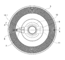
図1〜図4に示す外部制御式ファン・クラッチ装置は、駆動部(エンジン)の駆動によって回転する回転軸体(駆動軸)1に、第一軸受13、第二軸受14を介してケース2−1とカバー2−2とからなる密封器匣2が支承され、この密封器匣2内のトルク伝達室6内に回転軸体1に固着された駆動ディスク3が内装されている。この駆動ディスク3は、図3、図4に示すように、内部を中空となして設けた油溜り室5の一端部にトルク伝達室6に通ずる略三角形状の窓孔7が設けられ、この窓孔7の端部側の油溜り室5の側壁面にトルク伝達間隙に通ずる少なくとも一つの油循環流通孔8が設けられ、さらに前記略三角形状の窓孔7と反対側のディスク裏面側に後述する弁部材10の取付部11と、ディスク中央の軸孔9の外側に当該軸孔と同心円上に相対向する位置に円弧状のディスク支持脚部12が突出して設けられ、回転軸体1に密封器匣2を支承する第一軸受13、第二軸受14間の回転軸体1に固着されている。図中、4はセパレートプレートである。
The externally controlled fan / clutch device shown in FIGS. 1 to 4 is connected to a rotary shaft body (drive shaft) 1 that rotates by driving of a drive unit (engine) via a first bearing 13 and a second bearing 14. -1 and a cover 2-2 are supported, and a
駆動ディスク3に設けられた油循環流通孔8を開閉する油供給用の弁部材10は、板バネ10−1とアーマチャー10−2とからなり、当該弁部材のアーマチャー10−2が回転軸体1近傍に位置するように板バネ10−1基端部をディスク裏面側に設けた取付部11に捩子等により固着する。なお、弁部材10の板バネ10−1の基端部と反対側は駆動ディスク3に設けられた略三角形状の窓孔7からカバー2−2側に露出してその先端部が油循環流通孔8と相対向する位置にあることはいうまでもない。
An oil
他方、密封器匣2の駆動部側には、回転軸体1に第三軸受15を介して支承されたリング状の電磁石支持体17にリング状の電磁石16が支持され、この電磁石16と前記弁部材10間の回転軸体1の外周に固定された筒状の非磁性体リング19の外周に第1磁性体リング18が配置され、さらに電磁石16の電磁石支持体17と回転軸体1との間に第2磁性体リング20が電磁石支持体17に略接するように回転軸体1に外嵌固定されている。すなわち、本発明では、電磁石16の磁束を効率よく弁部材のアーマチャー10−2に伝えるため、第2磁性体リング20をさらに追加して弁部材10の作動機構(磁気回路)を構成している。
On the other hand, a ring-
上記構成のファン・クラッチ装置において、電磁石16がOFF(非励磁)の時はアーマチャー10−2が当該板バネ10−1の作用により駆動ディスク3の油循環流通孔8より離間することにより該油循環流通孔8が開き、油溜り室5とトルク伝達室6が連通し、油溜り室5内の油がトルク伝達室6内へ供給され、電磁石16がON(励磁)の時はアーマチャー10−2が当該板バネ10−1に抗して吸引されることにより、当該板バネ10−1が駆動ディスク3に圧接して油循環流通孔8が閉じられ、油溜り室5内の油がトルク伝達室6内へ供給されない。
すなわち、本発明では電磁石16がON(励磁)の時、前記したように磁気回路は電磁石16、第1磁性体リング18、アーマチャー10−2、回転軸体1及び第2磁性体リング20で構成され、磁束は図2に矢印で示すように電磁石16→第1磁性体リング18→アーマチャー10−2→回転軸体1→第2磁性体リング20の順に流れるので、電磁石16の磁束が効率よく弁部材10のアーマチャー10−2に伝えられ消費電力を低減できるのみならず、電磁石16の小型・軽量化もはかられるという効果が得られる。
In the fan / clutch device having the above-described configuration, when the
That is, in the present invention, when the
1 回転軸体(駆動軸)
2 密封器匣
2−1 ケース
2−2 カバー
3 駆動ディスク
4 セパレートプレート
5 油溜り室
6 トルク伝達室
7 窓孔
8 油循環流通孔
9 軸孔
10 弁部材
10−1 板バネ
10−2 アーマチャー
11 弁部材取付部
12 ディスク支持脚部
13 第一軸受
14 第二軸受
15 第三軸受
16 電磁石
17 電磁石支持体
18 第1磁性体リング
19 非磁性体リング
20 第2磁性体リング
1 Rotating shaft (drive shaft)
DESCRIPTION OF
Claims (1)
Priority Applications (4)
| Application Number | Priority Date | Filing Date | Title |
|---|---|---|---|
| JP2013119790A JP6358643B2 (en) | 2013-06-06 | 2013-06-06 | Externally controlled fan / clutch device |
| EP14170211.8A EP2811133B1 (en) | 2013-06-06 | 2014-05-28 | External control type fan clutch device |
| KR1020140068126A KR101586915B1 (en) | 2013-06-06 | 2014-06-05 | External control type fan clutch apparatus |
| US14/297,836 US9239086B2 (en) | 2013-06-06 | 2014-06-06 | External control type fan clutch device |
Applications Claiming Priority (1)
| Application Number | Priority Date | Filing Date | Title |
|---|---|---|---|
| JP2013119790A JP6358643B2 (en) | 2013-06-06 | 2013-06-06 | Externally controlled fan / clutch device |
Publications (2)
| Publication Number | Publication Date |
|---|---|
| JP2014238111A JP2014238111A (en) | 2014-12-18 |
| JP6358643B2 true JP6358643B2 (en) | 2018-07-18 |
Family
ID=50927913
Family Applications (1)
| Application Number | Title | Priority Date | Filing Date |
|---|---|---|---|
| JP2013119790A Active JP6358643B2 (en) | 2013-06-06 | 2013-06-06 | Externally controlled fan / clutch device |
Country Status (4)
| Country | Link |
|---|---|
| US (1) | US9239086B2 (en) |
| EP (1) | EP2811133B1 (en) |
| JP (1) | JP6358643B2 (en) |
| KR (1) | KR101586915B1 (en) |
Families Citing this family (8)
| Publication number | Priority date | Publication date | Assignee | Title |
|---|---|---|---|---|
| JP6391141B2 (en) * | 2014-01-31 | 2018-09-19 | 臼井国際産業株式会社 | Externally controlled fan / clutch device |
| JP6562749B2 (en) * | 2015-07-27 | 2019-08-21 | 臼井国際産業株式会社 | Externally controlled fan / clutch device |
| CA2996210A1 (en) | 2015-10-05 | 2017-04-13 | Horton, Inc. | Live center viscous clutch |
| US10612606B2 (en) | 2016-06-29 | 2020-04-07 | Horton, Inc. | Viscous clutch and associated electromagnetic coil |
| US10655688B2 (en) | 2018-02-16 | 2020-05-19 | Standard Motor Products, Inc. | Fan-coupling device with unitary magnetic pole construction |
| KR101958274B1 (en) * | 2018-10-16 | 2019-03-14 | 주식회사 이엠티 | Engine cooling control system having reinforced structure for pulling valve |
| AU2019426844A1 (en) | 2019-01-31 | 2021-09-09 | Horton, Inc. | Pump and wiper assembly, associated viscous clutch, and associated method |
| CN115516224A (en) | 2020-05-14 | 2022-12-23 | 霍顿公司 | Valve control system for viscous friction clutch |
Family Cites Families (12)
| Publication number | Priority date | Publication date | Assignee | Title |
|---|---|---|---|---|
| DE3243967C2 (en) * | 1982-11-27 | 1986-06-05 | Daimler-Benz Ag, 7000 Stuttgart | Fluid friction clutch |
| US4987986A (en) | 1989-07-24 | 1991-01-29 | General Motors Corporation | Electromagnetically actuated valve plate for a viscous fluid fan clutch |
| DE19533641B4 (en) * | 1995-09-12 | 2005-11-10 | Behr Gmbh & Co. Kg | Fluid friction clutch |
| DE19753725C2 (en) * | 1997-12-04 | 2001-03-08 | Behr Gmbh & Co | Fluid friction clutch |
| DE19925132B4 (en) * | 1999-06-02 | 2016-08-04 | Mahle International Gmbh | Fluid friction clutch |
| US6550596B2 (en) * | 2000-06-29 | 2003-04-22 | Usui Kokusai Sangyo Kaisha Limited | Externally controlled fan coupling device |
| DE10157822A1 (en) * | 2001-11-24 | 2003-06-05 | Behr Gmbh & Co | Electromagnetically controlled fluid friction clutch |
| ES2253618T3 (en) * | 2002-08-23 | 2006-06-01 | BEHR GMBH & CO. KG | VISCOSE FRICTION CLUTCH. |
| JP2004162911A (en) * | 2002-10-22 | 2004-06-10 | Usui Kokusai Sangyo Kaisha Ltd | External control type fan coupling apparatus |
| DE102005038060A1 (en) * | 2005-08-10 | 2007-02-22 | Ab Skf | Fluid friction clutch for motor vehicle fan, has double row tapered roller bearing arranged on side turned away from fastening surface of clutch and at front side of housing part, formed as O-arrangement and including outer and inner rings |
| DE102007042205A1 (en) * | 2007-09-05 | 2009-04-02 | Schaeffler Kg | Fluid friction clutch, for example for vehicle applications |
| JP5522677B2 (en) * | 2010-04-28 | 2014-06-18 | 臼井国際産業株式会社 | Highly reactive fluid fan and coupling device |
-
2013
- 2013-06-06 JP JP2013119790A patent/JP6358643B2/en active Active
-
2014
- 2014-05-28 EP EP14170211.8A patent/EP2811133B1/en active Active
- 2014-06-05 KR KR1020140068126A patent/KR101586915B1/en active IP Right Grant
- 2014-06-06 US US14/297,836 patent/US9239086B2/en active Active
Also Published As
| Publication number | Publication date |
|---|---|
| EP2811133B1 (en) | 2015-09-02 |
| KR20140143335A (en) | 2014-12-16 |
| US20140360834A1 (en) | 2014-12-11 |
| EP2811133A1 (en) | 2014-12-10 |
| US9239086B2 (en) | 2016-01-19 |
| JP2014238111A (en) | 2014-12-18 |
| KR101586915B1 (en) | 2016-01-19 |
Similar Documents
| Publication | Publication Date | Title |
|---|---|---|
| JP6358643B2 (en) | Externally controlled fan / clutch device | |
| US6915888B2 (en) | External control type fan-coupling device | |
| JP6391141B2 (en) | Externally controlled fan / clutch device | |
| US6550596B2 (en) | Externally controlled fan coupling device | |
| KR100675588B1 (en) | External control type fan-coupling device | |
| JP2004162911A5 (en) | ||
| KR101422986B1 (en) | High reaction type fluid fan coupling device | |
| JP6516281B2 (en) | Highly reactive fluid fan and clutch device | |
| JP2007120645A (en) | External control type fluid coupling | |
| US10670089B2 (en) | External control type fan clutch device | |
| JP2002195303A (en) | Magnetic fan clutch device | |
| JP4353396B2 (en) | Externally controlled fan coupling device | |
| JP2002081466A (en) | External control type fan coupling device | |
| JP2004286048A (en) | Fluid coupling device | |
| JP4353397B2 (en) | Externally controlled fan coupling device | |
| JP2002013556A (en) | External control type fan coupling device | |
| JP2009162326A (en) | Power transmission device | |
| GB2427255A (en) | Flux transmission member in electromagnetic viscous clutch | |
| JP2000074098A (en) | Temperature sensitive fluid fan coupling device | |
| JP2009257354A (en) | Driving force distribution device |
Legal Events
| Date | Code | Title | Description |
|---|---|---|---|
| A621 | Written request for application examination |
Free format text: JAPANESE INTERMEDIATE CODE: A621 Effective date: 20160512 |
|
| A131 | Notification of reasons for refusal |
Free format text: JAPANESE INTERMEDIATE CODE: A131 Effective date: 20170315 |
|
| A977 | Report on retrieval |
Free format text: JAPANESE INTERMEDIATE CODE: A971007 Effective date: 20170316 |
|
| A521 | Written amendment |
Free format text: JAPANESE INTERMEDIATE CODE: A523 Effective date: 20170509 |
|
| A131 | Notification of reasons for refusal |
Free format text: JAPANESE INTERMEDIATE CODE: A131 Effective date: 20170915 |
|
| A521 | Written amendment |
Free format text: JAPANESE INTERMEDIATE CODE: A523 Effective date: 20171113 |
|
| A131 | Notification of reasons for refusal |
Free format text: JAPANESE INTERMEDIATE CODE: A131 Effective date: 20180423 |
|
| A521 | Written amendment |
Free format text: JAPANESE INTERMEDIATE CODE: A523 Effective date: 20180604 |
|
| TRDD | Decision of grant or rejection written | ||
| A01 | Written decision to grant a patent or to grant a registration (utility model) |
Free format text: JAPANESE INTERMEDIATE CODE: A01 Effective date: 20180613 |
|
| A61 | First payment of annual fees (during grant procedure) |
Free format text: JAPANESE INTERMEDIATE CODE: A61 Effective date: 20180614 |
|
| R150 | Certificate of patent or registration of utility model |
Ref document number: 6358643 Country of ref document: JP Free format text: JAPANESE INTERMEDIATE CODE: R150 |