JP6358409B2 - Vehicle driving support control method and control device - Google Patents
Vehicle driving support control method and control device Download PDFInfo
- Publication number
- JP6358409B2 JP6358409B2 JP2017562459A JP2017562459A JP6358409B2 JP 6358409 B2 JP6358409 B2 JP 6358409B2 JP 2017562459 A JP2017562459 A JP 2017562459A JP 2017562459 A JP2017562459 A JP 2017562459A JP 6358409 B2 JP6358409 B2 JP 6358409B2
- Authority
- JP
- Japan
- Prior art keywords
- pedestrian
- driving support
- vehicle
- detected
- control
- Prior art date
- Legal status (The legal status is an assumption and is not a legal conclusion. Google has not performed a legal analysis and makes no representation as to the accuracy of the status listed.)
- Active
Links
- 238000000034 method Methods 0.000 title claims description 46
- 230000008569 process Effects 0.000 claims description 23
- 238000001514 detection method Methods 0.000 description 24
- 101000847024 Homo sapiens Tetratricopeptide repeat protein 1 Proteins 0.000 description 23
- 102100032841 Tetratricopeptide repeat protein 1 Human genes 0.000 description 23
- 102100022840 DnaJ homolog subfamily C member 7 Human genes 0.000 description 21
- 101000903053 Homo sapiens DnaJ homolog subfamily C member 7 Proteins 0.000 description 21
- 230000006870 function Effects 0.000 description 20
- 102100029211 E3 ubiquitin-protein ligase TTC3 Human genes 0.000 description 19
- 101000633723 Homo sapiens E3 ubiquitin-protein ligase TTC3 Proteins 0.000 description 19
- 238000004891 communication Methods 0.000 description 13
- 238000012545 processing Methods 0.000 description 13
- 230000007704 transition Effects 0.000 description 9
- 230000009471 action Effects 0.000 description 5
- 230000007423 decrease Effects 0.000 description 5
- 230000000694 effects Effects 0.000 description 5
- 239000012530 fluid Substances 0.000 description 5
- 230000008901 benefit Effects 0.000 description 4
- 102100034112 Alkyldihydroxyacetonephosphate synthase, peroxisomal Human genes 0.000 description 3
- 101000799143 Homo sapiens Alkyldihydroxyacetonephosphate synthase, peroxisomal Proteins 0.000 description 3
- 101150100956 VSP2 gene Proteins 0.000 description 3
- 238000000848 angular dependent Auger electron spectroscopy Methods 0.000 description 3
- 230000004043 responsiveness Effects 0.000 description 3
- 239000000779 smoke Substances 0.000 description 3
- 230000001133 acceleration Effects 0.000 description 2
- 238000007792 addition Methods 0.000 description 2
- 230000003111 delayed effect Effects 0.000 description 2
- 230000002265 prevention Effects 0.000 description 2
- 238000000926 separation method Methods 0.000 description 2
- 230000004397 blinking Effects 0.000 description 1
- 230000008859 change Effects 0.000 description 1
- 230000000052 comparative effect Effects 0.000 description 1
- 238000013461 design Methods 0.000 description 1
- 238000010586 diagram Methods 0.000 description 1
- 239000000446 fuel Substances 0.000 description 1
- 239000011521 glass Substances 0.000 description 1
- 230000006872 improvement Effects 0.000 description 1
- 230000002093 peripheral effect Effects 0.000 description 1
- 230000001172 regenerating effect Effects 0.000 description 1
- 230000004044 response Effects 0.000 description 1
- 230000035807 sensation Effects 0.000 description 1
- 239000007787 solid Substances 0.000 description 1
- 230000000007 visual effect Effects 0.000 description 1
Images


Classifications
-
- B—PERFORMING OPERATIONS; TRANSPORTING
- B60—VEHICLES IN GENERAL
- B60W—CONJOINT CONTROL OF VEHICLE SUB-UNITS OF DIFFERENT TYPE OR DIFFERENT FUNCTION; CONTROL SYSTEMS SPECIALLY ADAPTED FOR HYBRID VEHICLES; ROAD VEHICLE DRIVE CONTROL SYSTEMS FOR PURPOSES NOT RELATED TO THE CONTROL OF A PARTICULAR SUB-UNIT
- B60W30/00—Purposes of road vehicle drive control systems not related to the control of a particular sub-unit, e.g. of systems using conjoint control of vehicle sub-units, or advanced driver assistance systems for ensuring comfort, stability and safety or drive control systems for propelling or retarding the vehicle
- B60W30/08—Active safety systems predicting or avoiding probable or impending collision or attempting to minimise its consequences
- B60W30/09—Taking automatic action to avoid collision, e.g. braking and steering
-
- B—PERFORMING OPERATIONS; TRANSPORTING
- B60—VEHICLES IN GENERAL
- B60T—VEHICLE BRAKE CONTROL SYSTEMS OR PARTS THEREOF; BRAKE CONTROL SYSTEMS OR PARTS THEREOF, IN GENERAL; ARRANGEMENT OF BRAKING ELEMENTS ON VEHICLES IN GENERAL; PORTABLE DEVICES FOR PREVENTING UNWANTED MOVEMENT OF VEHICLES; VEHICLE MODIFICATIONS TO FACILITATE COOLING OF BRAKES
- B60T7/00—Brake-action initiating means
- B60T7/12—Brake-action initiating means for automatic initiation; for initiation not subject to will of driver or passenger
- B60T7/22—Brake-action initiating means for automatic initiation; for initiation not subject to will of driver or passenger initiated by contact of vehicle, e.g. bumper, with an external object, e.g. another vehicle, or by means of contactless obstacle detectors mounted on the vehicle
-
- B—PERFORMING OPERATIONS; TRANSPORTING
- B60—VEHICLES IN GENERAL
- B60W—CONJOINT CONTROL OF VEHICLE SUB-UNITS OF DIFFERENT TYPE OR DIFFERENT FUNCTION; CONTROL SYSTEMS SPECIALLY ADAPTED FOR HYBRID VEHICLES; ROAD VEHICLE DRIVE CONTROL SYSTEMS FOR PURPOSES NOT RELATED TO THE CONTROL OF A PARTICULAR SUB-UNIT
- B60W50/00—Details of control systems for road vehicle drive control not related to the control of a particular sub-unit, e.g. process diagnostic or vehicle driver interfaces
- B60W50/08—Interaction between the driver and the control system
- B60W50/14—Means for informing the driver, warning the driver or prompting a driver intervention
-
- G—PHYSICS
- G01—MEASURING; TESTING
- G01S—RADIO DIRECTION-FINDING; RADIO NAVIGATION; DETERMINING DISTANCE OR VELOCITY BY USE OF RADIO WAVES; LOCATING OR PRESENCE-DETECTING BY USE OF THE REFLECTION OR RERADIATION OF RADIO WAVES; ANALOGOUS ARRANGEMENTS USING OTHER WAVES
- G01S13/00—Systems using the reflection or reradiation of radio waves, e.g. radar systems; Analogous systems using reflection or reradiation of waves whose nature or wavelength is irrelevant or unspecified
- G01S13/66—Radar-tracking systems; Analogous systems
- G01S13/72—Radar-tracking systems; Analogous systems for two-dimensional tracking, e.g. combination of angle and range tracking, track-while-scan radar
- G01S13/723—Radar-tracking systems; Analogous systems for two-dimensional tracking, e.g. combination of angle and range tracking, track-while-scan radar by using numerical data
-
- G—PHYSICS
- G01—MEASURING; TESTING
- G01S—RADIO DIRECTION-FINDING; RADIO NAVIGATION; DETERMINING DISTANCE OR VELOCITY BY USE OF RADIO WAVES; LOCATING OR PRESENCE-DETECTING BY USE OF THE REFLECTION OR RERADIATION OF RADIO WAVES; ANALOGOUS ARRANGEMENTS USING OTHER WAVES
- G01S13/00—Systems using the reflection or reradiation of radio waves, e.g. radar systems; Analogous systems using reflection or reradiation of waves whose nature or wavelength is irrelevant or unspecified
- G01S13/86—Combinations of radar systems with non-radar systems, e.g. sonar, direction finder
- G01S13/867—Combination of radar systems with cameras
-
- G—PHYSICS
- G01—MEASURING; TESTING
- G01S—RADIO DIRECTION-FINDING; RADIO NAVIGATION; DETERMINING DISTANCE OR VELOCITY BY USE OF RADIO WAVES; LOCATING OR PRESENCE-DETECTING BY USE OF THE REFLECTION OR RERADIATION OF RADIO WAVES; ANALOGOUS ARRANGEMENTS USING OTHER WAVES
- G01S13/00—Systems using the reflection or reradiation of radio waves, e.g. radar systems; Analogous systems using reflection or reradiation of waves whose nature or wavelength is irrelevant or unspecified
- G01S13/88—Radar or analogous systems specially adapted for specific applications
- G01S13/93—Radar or analogous systems specially adapted for specific applications for anti-collision purposes
- G01S13/931—Radar or analogous systems specially adapted for specific applications for anti-collision purposes of land vehicles
-
- G—PHYSICS
- G01—MEASURING; TESTING
- G01S—RADIO DIRECTION-FINDING; RADIO NAVIGATION; DETERMINING DISTANCE OR VELOCITY BY USE OF RADIO WAVES; LOCATING OR PRESENCE-DETECTING BY USE OF THE REFLECTION OR RERADIATION OF RADIO WAVES; ANALOGOUS ARRANGEMENTS USING OTHER WAVES
- G01S7/00—Details of systems according to groups G01S13/00, G01S15/00, G01S17/00
- G01S7/02—Details of systems according to groups G01S13/00, G01S15/00, G01S17/00 of systems according to group G01S13/00
- G01S7/41—Details of systems according to groups G01S13/00, G01S15/00, G01S17/00 of systems according to group G01S13/00 using analysis of echo signal for target characterisation; Target signature; Target cross-section
-
- G—PHYSICS
- G05—CONTROLLING; REGULATING
- G05D—SYSTEMS FOR CONTROLLING OR REGULATING NON-ELECTRIC VARIABLES
- G05D1/00—Control of position, course or altitude of land, water, air, or space vehicles, e.g. automatic pilot
- G05D1/02—Control of position or course in two dimensions
- G05D1/021—Control of position or course in two dimensions specially adapted to land vehicles
- G05D1/0231—Control of position or course in two dimensions specially adapted to land vehicles using optical position detecting means
- G05D1/0246—Control of position or course in two dimensions specially adapted to land vehicles using optical position detecting means using a video camera in combination with image processing means
-
- G—PHYSICS
- G05—CONTROLLING; REGULATING
- G05D—SYSTEMS FOR CONTROLLING OR REGULATING NON-ELECTRIC VARIABLES
- G05D1/00—Control of position, course or altitude of land, water, air, or space vehicles, e.g. automatic pilot
- G05D1/02—Control of position or course in two dimensions
- G05D1/021—Control of position or course in two dimensions specially adapted to land vehicles
- G05D1/0257—Control of position or course in two dimensions specially adapted to land vehicles using a radar
-
- G—PHYSICS
- G06—COMPUTING; CALCULATING OR COUNTING
- G06V—IMAGE OR VIDEO RECOGNITION OR UNDERSTANDING
- G06V20/00—Scenes; Scene-specific elements
- G06V20/50—Context or environment of the image
- G06V20/56—Context or environment of the image exterior to a vehicle by using sensors mounted on the vehicle
- G06V20/58—Recognition of moving objects or obstacles, e.g. vehicles or pedestrians; Recognition of traffic objects, e.g. traffic signs, traffic lights or roads
-
- G—PHYSICS
- G06—COMPUTING; CALCULATING OR COUNTING
- G06V—IMAGE OR VIDEO RECOGNITION OR UNDERSTANDING
- G06V40/00—Recognition of biometric, human-related or animal-related patterns in image or video data
- G06V40/10—Human or animal bodies, e.g. vehicle occupants or pedestrians; Body parts, e.g. hands
- G06V40/103—Static body considered as a whole, e.g. static pedestrian or occupant recognition
-
- G—PHYSICS
- G08—SIGNALLING
- G08G—TRAFFIC CONTROL SYSTEMS
- G08G1/00—Traffic control systems for road vehicles
- G08G1/16—Anti-collision systems
-
- G—PHYSICS
- G08—SIGNALLING
- G08G—TRAFFIC CONTROL SYSTEMS
- G08G1/00—Traffic control systems for road vehicles
- G08G1/16—Anti-collision systems
- G08G1/166—Anti-collision systems for active traffic, e.g. moving vehicles, pedestrians, bikes
-
- B—PERFORMING OPERATIONS; TRANSPORTING
- B60—VEHICLES IN GENERAL
- B60W—CONJOINT CONTROL OF VEHICLE SUB-UNITS OF DIFFERENT TYPE OR DIFFERENT FUNCTION; CONTROL SYSTEMS SPECIALLY ADAPTED FOR HYBRID VEHICLES; ROAD VEHICLE DRIVE CONTROL SYSTEMS FOR PURPOSES NOT RELATED TO THE CONTROL OF A PARTICULAR SUB-UNIT
- B60W50/00—Details of control systems for road vehicle drive control not related to the control of a particular sub-unit, e.g. process diagnostic or vehicle driver interfaces
- B60W50/08—Interaction between the driver and the control system
- B60W50/14—Means for informing the driver, warning the driver or prompting a driver intervention
- B60W2050/143—Alarm means
-
- B—PERFORMING OPERATIONS; TRANSPORTING
- B60—VEHICLES IN GENERAL
- B60W—CONJOINT CONTROL OF VEHICLE SUB-UNITS OF DIFFERENT TYPE OR DIFFERENT FUNCTION; CONTROL SYSTEMS SPECIALLY ADAPTED FOR HYBRID VEHICLES; ROAD VEHICLE DRIVE CONTROL SYSTEMS FOR PURPOSES NOT RELATED TO THE CONTROL OF A PARTICULAR SUB-UNIT
- B60W2420/00—Indexing codes relating to the type of sensors based on the principle of their operation
- B60W2420/40—Photo or light sensitive means, e.g. infrared sensors
- B60W2420/403—Image sensing, e.g. optical camera
-
- B60W2420/408—
-
- B—PERFORMING OPERATIONS; TRANSPORTING
- B60—VEHICLES IN GENERAL
- B60W—CONJOINT CONTROL OF VEHICLE SUB-UNITS OF DIFFERENT TYPE OR DIFFERENT FUNCTION; CONTROL SYSTEMS SPECIALLY ADAPTED FOR HYBRID VEHICLES; ROAD VEHICLE DRIVE CONTROL SYSTEMS FOR PURPOSES NOT RELATED TO THE CONTROL OF A PARTICULAR SUB-UNIT
- B60W2554/00—Input parameters relating to objects
-
- G—PHYSICS
- G01—MEASURING; TESTING
- G01S—RADIO DIRECTION-FINDING; RADIO NAVIGATION; DETERMINING DISTANCE OR VELOCITY BY USE OF RADIO WAVES; LOCATING OR PRESENCE-DETECTING BY USE OF THE REFLECTION OR RERADIATION OF RADIO WAVES; ANALOGOUS ARRANGEMENTS USING OTHER WAVES
- G01S13/00—Systems using the reflection or reradiation of radio waves, e.g. radar systems; Analogous systems using reflection or reradiation of waves whose nature or wavelength is irrelevant or unspecified
- G01S13/88—Radar or analogous systems specially adapted for specific applications
- G01S13/93—Radar or analogous systems specially adapted for specific applications for anti-collision purposes
- G01S13/931—Radar or analogous systems specially adapted for specific applications for anti-collision purposes of land vehicles
- G01S2013/9327—Sensor installation details
- G01S2013/93271—Sensor installation details in the front of the vehicles
Description
本発明は、外界認識センサとしてカメラとレーダーを備え、走行中、自車両と検出された歩行者との接触可能性が判断されると運転支援制御を実施する車両の運転支援制御方法及び制御装置に関する。 The present invention includes a camera and a radar as an external recognition sensor, and a vehicle driving support control method and a control apparatus that perform driving support control when it is determined that the vehicle can be contacted with a detected pedestrian during traveling. About.
従来、歩行者の誤検出防止を目的とし、カメラとレーダーを備え、カメラにより撮像された画像情報に基づき対象物候補の方向を算出し、レーダーが検出した対象物候補の方向を比較する。そして、比較結果に応じて対象物候補が歩行者であるか否かを判定する対象物検出装置が知られている(例えば、特許文献1参照)。 Conventionally, for the purpose of preventing erroneous detection of pedestrians, a camera and a radar are provided, the direction of the target object candidate is calculated based on image information captured by the camera, and the direction of the target object candidate detected by the radar is compared. And the target object detection apparatus which determines whether a target object candidate is a pedestrian according to a comparison result is known (for example, refer patent document 1).
しかしながら、上記従来装置にあっては、カメラとレーダーによる2つの対象物候補の距離と方向を比較し、2つの対象物候補の距離と方向が一致していると判断されると、対象物候補を歩行者であると判定する。このため、従来装置を運転支援制御システムに採用すると、2つの対象物候補の距離と方向が一致しているとの比較判断により歩行者判定が完了するまでは、運転支援制御の実施が許可されない。よって、歩行者判定が完了するまで運転支援制御を実施できず、運転支援制御の開始が遅れてしまう、という問題がある。 However, in the above-described conventional apparatus, when the distance and direction of the two object candidates by the camera and the radar are compared and it is determined that the distance and the direction of the two object candidates match, the object candidate Is determined to be a pedestrian. For this reason, when the conventional device is adopted in the driving support control system, the driving support control is not permitted until the pedestrian determination is completed by the comparison determination that the distance and the direction of the two object candidates coincide with each other. . Therefore, there is a problem that the driving support control cannot be performed until the pedestrian determination is completed, and the start of the driving support control is delayed.
本発明は、上記問題に着目してなされたもので、走行中、歩行者の誤判定防止機能を確保しつつ、運転支援制御を開始する開始タイミングの早期化を達成する車両の運転支援制御方法及び制御装置を提供することを目的とする。 The present invention has been made paying attention to the above-mentioned problem. A vehicle driving support control method that achieves early start timing for starting driving support control while ensuring a function for preventing erroneous determination of pedestrians during traveling. And it aims at providing a control apparatus.
上記目的を達成するため、本発明は、自車両の前方情報を取得する外界認識センサを備える。外界認識センサとして、カメラとレーダーを備える。外界認識センサにより歩行者が検出されると、自車両が歩行者へ接触するのを回避する運転支援制御を実施する。
カメラからの画像信号に基づいて自車両の前方に存在する対象物が歩行者候補であると検出されると、検出された歩行者候補を制御対象として運転支援制御を開始する。
その後、カメラにより検出された歩行者候補が、レーダーからの反射波により検出された対象物とマッチングするかどうかを比較判定し、マッチングが成立すると運転支援制御を継続し、マッチングが成立しないと運転支援制御を解除する。In order to achieve the above object, the present invention includes an external recognition sensor that acquires forward information of the host vehicle. A camera and radar are provided as external recognition sensors. When a pedestrian is detected by the external recognition sensor, driving support control is performed to avoid the vehicle from contacting the pedestrian.
When it is detected that an object existing ahead of the host vehicle is a pedestrian candidate based on an image signal from the camera, driving support control is started with the detected pedestrian candidate as a control target.
After that, the pedestrian candidate detected by the camera is compared with the object detected by the reflected wave from the radar to determine whether it matches, and if the matching is established, the driving support control is continued. If the matching is not established, the driving is continued. Release support control.
よって、カメラとレーダーを用いて自車両の前方に存在する歩行者を判定する場合、形状認識により単独で歩行者検出が可能なカメラからの情報で歩行者候補が検出されると、比較判定結果を待つことなく、運転支援制御を開始する。
そして、自車両の前方に歩行者が存在するときに対象物認識性がカメラより高いレーダーにより検出される対象物を比較判定に用い、運転支援制御が開始された後、カメラにより検出された歩行者候補と対象物がマッチングするかどうかが比較判定される。そして、マッチングが成立すると運転支援制御が継続され、マッチングが成立しないと運転支援制御が解除される。
この結果、走行中、歩行者の誤判定防止機能を確保しつつ、運転支援制御を開始する開始タイミングの早期化を達成することができる。Therefore, when determining a pedestrian existing in front of the host vehicle using a camera and a radar, if a pedestrian candidate is detected by information from a camera capable of pedestrian detection alone by shape recognition, a comparison determination result Start driving support control without waiting.
Then, when a pedestrian is present in front of the host vehicle, the object detected by the radar having higher object recognition than the camera is used for comparison determination, and after the driving support control is started, the walking detected by the camera It is determined whether the candidate and the object match. When the matching is established, the driving support control is continued, and when the matching is not established, the driving assistance control is canceled.
As a result, it is possible to achieve early start timing for starting the driving support control while ensuring the function of preventing erroneous determination of pedestrians while traveling.
以下、本発明の車両の運転支援制御方法及び制御装置を実現する最良の形態を、図面に示す実施例1に基づいて説明する。 Hereinafter, the best mode for realizing a driving support control method and a control apparatus for a vehicle according to the present invention will be described based on a first embodiment shown in the drawings.
まず、構成を説明する。
実施例1における運転支援制御方法及び制御装置は、エマージェンシーブレーキ制御システムと呼ばれる自動ブレーキ制御を実施するシステムが搭載された電動車両(ハイブリッド車、電気自動車、燃料電池車、等)に適用したものである。以下、実施例1の運転支援制御装置の構成を、「運転支援システムの全体構成」、「自動ブレーキ制御処理構成」に分けて説明する。First, the configuration will be described.
The driving support control method and the control device in the first embodiment are applied to an electric vehicle (hybrid vehicle, electric vehicle, fuel cell vehicle, etc.) equipped with a system for performing automatic brake control called an emergency brake control system. is there. Hereinafter, the configuration of the driving support control apparatus according to the first embodiment will be described by being divided into “the entire configuration of the driving support system” and “the automatic brake control processing configuration”.
[運転支援システムの全体構成]
図1は、実施例1の運転支援制御方法及び制御装置が適用された運転支援システムの全体構成を示す。以下、図1に基づき、運転支援システムの全体構成を説明する。[Overall configuration of driving support system]
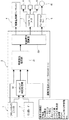
FIG. 1 illustrates an overall configuration of a driving support system to which the driving support control method and the control device according to the first embodiment are applied. Hereinafter, the overall configuration of the driving support system will be described with reference to FIG.
前記運転支援システムは、図1に示すように、フロントカメラユニット1と、ミリ波レーダー2と、運転支援コントローラ3と、電動型制御ブレーキユニット4と、を主要構成として備えている。なお、周辺構成として、コンビネーションメータ5と、警報ブザー6と、ブレーキ警告灯7と、ブレーキ警告表示8と、ブレーキホールドリレー9と、ストップランプ10と、を備えている。
As shown in FIG. 1, the driving support system includes a
前記フロントカメラユニット1は、CCDやCMOS等の撮像素子を用いて自車前方の状況を撮像可能なカメラユニットであり、例えば、ウインドシールドガラスの中央上部位置等に取り付けられ、自車前方を撮像領域として画像情報を検出する。検出した画像情報は、CAN通信により運転支援コントローラ3に送信される。
なお、「CAN」とは、「Controller Area Network」の略称である。The
“CAN” is an abbreviation for “Controller Area Network”.
前記ミリ波レーダー2は、ミリ波帯の電波を用いて自車前方の状況を探知可能なレーダーシステムであり、例えば、フロントバンパ等に取り付けられ、前方にミリ波を照射して自車前方に存在する対象物(先行車や歩行者等)からの反射波を検出する。検出した反射波による対象物の有無情報や対象物の方向/位置情報は、CAN通信により運転支援コントローラ3に送信される。
The
前記運転支援コントローラ3は、制御に必要な信号を転送するもので、例えば、グローブボックスの奥位置等に取り付けられ、自動ブレーキ制御等の運転支援制御を行う。この運転支援コントローラ3は、CAN通信信号に基づき、フロントカメラユニット1及びミリ波レーダー2からの情報を受信する。これ以外に、図外の各コントローラからのCAN通信信号に基づき、車輪速、アクセル開度、ブレーキスイッチ、ブレーキ液圧、シフトポジション、ステアリング角、ステアリング角速度、加速度、ヨーレート、システムON/OFF状態、等の自車両情報を受信する。運転支援コントローラ3からは、自動ブレーキ制御開始後において予備制動や本制動を作動させるとき、電動型制御ブレーキユニット4に対してCAN通信線を介してブレーキ液圧指令信号を送信する。そして、自動ブレーキ制御が開始されると、コンビネーションメータ5に対してCAN通信線を介してブザー出力信号とメータディスプレイ信号を送信する。さらに、自動ブレーキ制御開始後において予備制動や本制動を作動させるとき、ブレーキホールドリレー9に対してストップランプ駆動信号を送信する。
The
ここで、運転支援コントローラ3は、「ADASコントロールユニット(ADAS C/U)」と呼ばれているもので、自動ブレーキ制御機能(FEB機能)を含む複数の運転操作を支援する統合コントローラ機能を持つ。自動ブレーキ制御機能(FEB機能)以外の運転支援制御機能としては、例えば、オートクルーズ制御機能(ACC機能)、レーンキープ制御機能(LKS機能)、車両挙動制御機能(VDC機能)、等がある。
なお、「ADAS」は、「Advanced Driver Assistance System」の略称である。Here, the
“ADAS” is an abbreviation for “Advanced Driver Assistance System”.
前記電動型制御ブレーキユニット4は、コントロールユニットとマスタシリンダと電動ブースタ(電動車両において回生協調制動に対応)を一体化し、ABS/VDCアクチュエータに送る液圧を制御するユニットである。この電動型制御ブレーキユニット4のコントロールユニットは、運転支援コントローラ3からCAN通信線を介してブレーキ液圧指令信号を受信すると、電動ブースタのモータを駆動し、ピストンを移動させてマスタシリンダ液圧を発生させる。この電動型制御ブレーキユニット4からは、運転者によるブレーキ操作を検出すると、ドライバブレーキ検出信号を運転支援コントローラ3に対しCAN通信線を介して送信する。
The electric
前記コンビネーションメータ5は、運転支援コントローラ3からCAN通信線を介してブザー出力信号を受信すると警報ブザー6を吹鳴する。また、運転支援コントローラ3からCAN通信線を介してメータディスプレイ信号を受信すると、ブレーキ警告灯7の点滅表示や点灯表示をすると共にブレーキ警告表示8を点灯表示する。
The combination meter 5 sounds an
前記ブレーキホールドリレー9は、運転支援コントローラ3からCAN通信線を介してストップランプ駆動信号を受信すると、ストップランプ回路をバイパスさせてストップランプ10を点灯させる。
When the brake hold relay 9 receives a stop lamp drive signal from the driving
前記運転支援コントローラ3は、図1に示すように、物体確定処理部31と、マッチング判定処理部32と、制御指令演算部33と、を有する。
As shown in FIG. 1, the driving
前記物体確定処理部31は、自車両情報とカメラ情報を取得し、フロントカメラユニット1からの画像情報に基づき、車両前方に存在する先行車や歩行者等を含む対象物を判定し、さらに、対象物の中から歩行者候補を検出する。そして、自車両の予想進路上に歩行者候補が一定時間存在していることが検出されると、検出された歩行者候補を制御対象として自動ブレーキ制御の実施を許可する。自動ブレーキ制御の実施を許可した後は、自車両と歩行者候補との距離を相対速度(=自車速度)で除算することで接触予測時間TTCが求められる。そして、接触予測時間TTCが、警報閾値TTC1以下か、予備制動閾値TTC2以下か、本制動閾値TTC3以下かを判断する。接触予測時間TTCが警報閾値TTC1以下になると警報による自動ブレーキ制御を開始する。接触予測時間TTCが予備制動閾値TTC2以下になると警報と共に緩ブレーキによる予備制動を開始する。接触予測時間TTCが本制動閾値TTC3以下になると警報と共に急ブレーキによる本制動を開始する。なお、「TTC」とは「Time To Collision」の略称である。
The object
前記マッチング判定処理部32は、自動ブレーキ制御を開始した後、フロントカメラユニット1により検出された歩行者候補が、ミリ波レーダー2からの反射波により検出された対象物とマッチングするかどうかを比較判定する。即ち、フロントカメラユニット1により検出される歩行者候補の位置情報を中心点として許容誤差領域を設定する。そして、ミリ波レーダー2からの反射波により検出された複数の対象物の方向/距離による位置情報のうち、歩行者候補に対し最も近接する対象物の位置情報を選択する。このミリ波レーダー2からの選択された対象物の位置情報が、許容誤差領域内に存在するかどうか比較判断する。そして、選択された対象物が許容誤差領域内に存在する状態であると判断された時間の積算値が、所定時間(例えば、200msec)を経過するとマッチング成立とし、フロントカメラユニット1により検出された歩行者候補を制御対象の歩行者であると判定し、自動ブレーキ制御を継続する。一方、マッチング判定を開始してから所定時間が経過してもマッチング不成立であると、フロントカメラユニット1により検出された歩行者候補が制御対象となる歩行者ではないと判定し、自動ブレーキ制御を解除する。
The matching
前記制御指令演算部33は、物体確定処理部32からの処理結果を受けて制御指令を演算し、電動型制御ブレーキユニット4とコンビネーションメータ5とブレーキホールドリレー9に対してCAN通信線を介して指令信号を出力する。電動型制御ブレーキユニット4に対しては、接触予測時間TTCが予備制動閾値TTC2以下になると緩ブレーキによる予備制動を行うブレーキ液圧指令信号を出力し、接触予測時間TTCが本制動閾値TTC3以下になると急ブレーキによる本制動を行うブレーキ液圧指令信号を出力する。コンビネーションメータ5に対しては、接触予測時間TTCが警報閾値TTC1以下になると、警報ブザー6を吹鳴するブザー出力信号、ブレーキ警告灯7の点滅又は点灯表示をする警告表示信号、及びブレーキ警告表示8を点灯表示するメータディスプレイ信号を出力する。ブレーキホールドリレー9に対しては、接触予測時間TTCが予備制動閾値TTC1以下になると、ストップランプ回路をバイパスさせてストップランプ10を点灯させるストップランプ駆動信号を出力する。
The control
[自動ブレーキ制御処理構成]
図2は、実施例1の運転支援コントローラ3にて実行される制御対象が歩行者であるときの自動ブレーキ制御処理の流れを示す。以下、自動ブレーキ制御処理構成をあらわす図2の各ステップについて説明する。[Automatic brake control processing configuration]
FIG. 2 shows the flow of the automatic brake control process when the control target executed by the driving
ステップS1では、自車両情報を取得し、ステップS2へ進む。
ここで、「自車両情報」とは、車載された各コントローラからのCAN通信信号により受信される、車輪速、アクセル開度、ブレーキスイッチ、ブレーキ液圧、シフトポジション、ステアリング角、ステアリング角速度、加速度、ヨーレート、システムON/OFF状態、等のことをいう。In step S1, own vehicle information is acquired and it progresses to step S2.
Here, “own vehicle information” means wheel speed, accelerator opening, brake switch, brake fluid pressure, shift position, steering angle, steering angular velocity, acceleration received by CAN communication signals from each controller mounted on the vehicle. , Yaw rate, system ON / OFF status, etc.
ステップS2では、ステップS1での自車両情報の取得に続き、フロントカメラユニット1からのカメラ情報を取得し、ステップS3へ進む。
ここで、「カメラ情報」とは、フロントカメラユニット1から取得される車両前方の画像情報のことをいう。In step S2, following the acquisition of the host vehicle information in step S1, camera information from the
Here, “camera information” refers to image information in front of the vehicle acquired from the
ステップS3では、ステップS2でのカメラ情報取得に続き、カメラ情報に基づいて、歩行者候補が検出されたか否かを判断する。YES(歩行者候補検出)の場合はステップS4へ進み、NO(歩行者候補非検出)の場合はステップS1へ戻る。
ここで、「歩行者候補の検出」は、フロントカメラユニット1からの画像情報に基いて車両前方に存在する様々な対象物を検出し、さらに、先行車を含む複数の対象物の中から歩行者候補を検出するという、周知の歩行者候補検出手法を用いて行う。In step S3, following the acquisition of camera information in step S2, it is determined whether a pedestrian candidate has been detected based on the camera information. If YES (pedestrian candidate detection), the process proceeds to step S4. If NO (pedestrian candidate non-detection), the process returns to step S1.
Here, “detection of pedestrian candidates” detects various objects existing in front of the vehicle based on image information from the
なお、周知の歩行者候補検出手法とは、例えば、特開2009-294842号公報に記載されているように、カメラにより撮像された画像から特徴点を抽出し、抽出された特徴点の移動情報に基づいて対象立体物を含む対象領域を抽出する。そして、対象領域に関する移動情報と対象領域の周囲に設定された比較領域に関する移動情報を比較し、比較結果に基づいて対象立体物が歩行者候補であるか否かを検出する。また、特開2013-228915号公報に記載されているように、カメラにより撮像された画像から歩行者の足が存在する可能性のある領域を抽出し、抽出された候補領域内に設定された処理領域を2つのクラスに分ける。そして、2つのクラスの間の輝度値の分離度の分布をあらわすヒストグラムを作成し、作成された分離度のヒストグラム形状に基づいて対象立体物が歩行者候補であるか否かを検出する。さらに、特開2014-35560号公報に記載されているように、注目領域内に検出される移動速度情報が飛び出しであるか否かを判定する際の閾値を自車両が直進走行か旋回走行かで変更し、死角から出現する歩行者候補をいち早く検出する。 Note that the well-known pedestrian candidate detection method is, for example, as described in Japanese Patent Application Laid-Open No. 2009-294842, extracting feature points from an image captured by a camera, and movement information of the extracted feature points The target area including the target three-dimensional object is extracted based on the above. Then, the movement information regarding the target area is compared with the movement information regarding the comparison area set around the target area, and it is detected whether the target three-dimensional object is a pedestrian candidate based on the comparison result. Further, as described in JP 2013-228915 A, an area where a pedestrian's foot may exist is extracted from an image captured by a camera, and set in the extracted candidate area Divide the processing area into two classes. Then, a histogram representing the distribution of the degree of separation of the luminance values between the two classes is created, and whether or not the target three-dimensional object is a pedestrian candidate is detected based on the created histogram shape of the degree of separation. Furthermore, as described in Japanese Patent Laid-Open No. 2014-35560, the threshold for determining whether or not the moving speed information detected in the attention area is a pop-up is whether the vehicle is traveling straight or turning. The pedestrian candidate appearing from the blind spot is detected quickly.
ステップS4では、ステップS3での歩行者候補検出であるとの判断に続き、自動ブレーキ制御の実施を許可し、ステップS5へ進む。
ここで、「自動ブレーキ制御の実施許可」とは、例えば、歩行者候補が検出されたときの接触予測時間TTCが警報閾値TTC1を超えている値から徐々に低下するとき、警報モード→予備制動モード→本制動モードへと遷移する自動ブレーキ制御を許可することをいう。In step S4, following the determination that it is pedestrian candidate detection in step S3, the execution of automatic brake control is permitted, and the process proceeds to step S5.
Here, “permission of automatic brake control” means, for example, when the predicted contact time TTC when a pedestrian candidate is detected gradually decreases from a value exceeding the alarm threshold TTC1, the alarm mode → preliminary braking This refers to permitting automatic brake control for transition from mode to full braking mode.
ステップS5では、ステップS4での自動ブレーキ制御の実施許可に続き、接触予測時間TTCが、警報閾値TTC1以下であるか、予備制動閾値TTC2以下であるか、本制動閾値TTC3以下であるか否かを判断する。YES(TTC≦TTC1,TTC2,TTC3)の場合はステップS6へ進み、NO(TTC>TTC1)の場合はステップS5の判断を繰り返す。
ここで、「警報閾値TTC1」と「予備制動閾値TTC2」と「本制動閾値TTC3」とは、図3のTTC閾値マップに示すように、警報閾値TTC1>予備制動閾値TTC2>本制動閾値TTC3の関係にて設定される。In step S5, whether or not the predicted contact time TTC is equal to or less than the alarm threshold value TTC1, the preliminary braking threshold value TTC2, or the actual braking threshold value TTC3, following the automatic brake control permission in step S4. Judging. If YES (TTC ≦ TTC1, TTC2, TTC3), the process proceeds to step S6. If NO (TTC> TTC1), the determination in step S5 is repeated.
Here, “alarm threshold value TTC1”, “preliminary braking threshold value TTC2”, and “main braking threshold value TTC3” are as follows: alarm threshold value TTC1> preliminary braking threshold value TTC2> main braking threshold value TTC3 Set by relationship.
TTC閾値を図3に示すTTC閾値マップにより詳しく説明すると、警報閾値TTC1は、自車速度(VSP)にかかわらず一定の高い接触予測時間TTCの値に設定される。自車速度≦第1速度VSP1の車速領域における予備制動閾値TTC2は、本制動閾値TTC3と一致させた一定値に設定される。第1速度VSP1<自車速度<第2速度VSP2の車速領域における予備制動閾値TTC2は、自車速度(VSP)が高くなるほど比例的に上昇する特性に設定される。自車速度≧第2速度VSP2の車速領域における予備制動閾値TTC2は、警報閾値TTC1より少し小さい一定値に設定される。本制動閾値TTC3は、自車速度(VSP)にかかわらず一定の低い接触予測時間TTCの値に設定される。即ち、自車速度≦第1速度VSP1の低車速領域においては、予備制動がなく、警報と本制動による自動ブレーキ制御になる。第1速度VSP1<自車速度<第2速度VSP2の車速領域においては、自車速度が高速であるほど予備制動のTTC領域が広く、自車速度が低速であるほど予備制動のTTC領域が狭くなる。
なお、自動ブレーキ制御での制御対象が先行車の場合には、TTC閾値マップの横軸を自車両と先行車の相対速度として自動ブレーキ制御が実施される。The TTC threshold value will be described in detail with reference to the TTC threshold map shown in FIG. 3. The alarm threshold value TTC1 is set to a constant high predicted contact time TTC regardless of the vehicle speed (VSP). The preliminary braking threshold value TTC2 in the vehicle speed region where the host vehicle speed is equal to or less than the first speed VSP1 is set to a constant value matched with the main braking threshold value TTC3. The preliminary braking threshold value TTC2 in the vehicle speed region where the first speed VSP1 <the host vehicle speed <the second speed VSP2 is set to a characteristic that increases proportionally as the host vehicle speed (VSP) increases. The preliminary braking threshold value TTC2 in the vehicle speed region where the host vehicle speed ≧ the second speed VSP2 is set to a constant value that is slightly smaller than the warning threshold value TTC1. The braking threshold value TTC3 is set to a constant low predicted contact time TTC regardless of the vehicle speed (VSP). That is, in the low vehicle speed region where the host vehicle speed is equal to or less than the first speed VSP1, there is no preliminary braking, and automatic braking control is performed by warning and main braking. In the vehicle speed region where the first speed VSP1 <the host vehicle speed <the second speed VSP2, the TTC region for preliminary braking is wider as the host vehicle speed is higher, and the TTC region for preliminary braking is narrower as the host vehicle speed is lower. Become.
In addition, when the control target in the automatic brake control is a preceding vehicle, the automatic brake control is performed with the horizontal axis of the TTC threshold map as the relative speed between the host vehicle and the preceding vehicle.
ステップS6では、ステップS5でのTTC≦TTC1,TTC2,TTC3であるとの判断に続き、自動ブレーキ制御を開始し、ステップS7へ進む。
ここで、歩行者候補の検出により自動ブレーキ制御が許可されたときの接触予測時間TTCが警報閾値TTC1以下であれば、図4に示すように、警報モード→予備制動モード→本制動モードへと遷移する自動ブレーキ制御を開始する。なお、歩行者候補の検出により自動ブレーキ制御が許可されたときの接触予測時間TTCが予備制動閾値TTC2以下であれば、予備制動モード(警報)→本制動モード(警報)へとモード遷移する自動ブレーキ制御を開始する。また、歩行者候補の検出により自動ブレーキ制御が許可されたときの接触予測時間TTCが本制動閾値TTC3以下であれば、本制動モード(警報)を実施する自動ブレーキ制御を開始する。In step S6, following the determination that TTC ≦ TTC1, TTC2, TTC3 in step S5, automatic brake control is started, and the process proceeds to step S7.
Here, if the predicted contact time TTC when automatic brake control is permitted by detection of a pedestrian candidate is equal to or less than the alarm threshold value TTC1, as shown in FIG. 4, the alarm mode → preliminary braking mode → main braking mode is set. Start the transition automatic brake control. If the predicted contact time TTC when automatic brake control is permitted by detection of a pedestrian candidate is less than or equal to the preliminary braking threshold TTC2, the automatic transition of the mode from the preliminary braking mode (alarm) to the main braking mode (alarm) is performed. Start brake control. Further, if the predicted contact time TTC when automatic brake control is permitted by detection of a pedestrian candidate is equal to or less than the main braking threshold TTC3, automatic brake control for executing the main braking mode (alarm) is started.
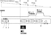
自動ブレーキ制御が実施される際に自車両と歩行者の接触予測時間TTCが一定勾配で低下するときの警報モード・予備制動モード・本制動モードによるモード遷移を、図4に示す自動ブレーキタイムチャートにより説明する。自車両Aと歩行者Bの接触予測時間TTCが警報閾値TTC1を超えている時刻t1までの間は、自動ブレーキ制御は開始されない。時刻t1にて接触予測時間TTCが警報閾値TTC1以下になると、警告表示やブザーにより運転者に対して視覚と聴覚により訴える緊急警報による運転支援が開始される。時刻t2にて接触予測時間TTCが予備制動閾値TTC2以下になると、緊急警報に加え、緩ブレーキによる予備制動が開始される。時刻t3にて接触予測時間TTCが本制動閾値TTC3以下になると、緊急警報に加え、急ブレーキによる本制動が開始され、自車両Aと歩行者Bの接触が回避される。なお、この自動ブレーキ制御に関しては、マッチング判定による成立/不成立にかかわらず、同じモード遷移による制御が継続して実施される。 The automatic brake time chart shown in FIG. 4 shows the mode transition in the alarm mode, the preliminary braking mode, and the main braking mode when the predicted contact time TTC between the host vehicle and the pedestrian decreases at a constant gradient when the automatic brake control is performed. Will be described. The automatic brake control is not started until time t1 when the predicted contact time TTC between the host vehicle A and the pedestrian B exceeds the warning threshold value TTC1. When the predicted contact time TTC becomes equal to or less than the alarm threshold value TTC1 at time t1, driving assistance based on an emergency warning that appeals to the driver visually and audibly by a warning display or buzzer is started. When the predicted contact time TTC becomes equal to or less than the preliminary braking threshold value TTC2 at time t2, preliminary braking by slow braking is started in addition to the emergency warning. When the predicted contact time TTC becomes equal to or less than the main braking threshold TTC3 at time t3, in addition to the emergency warning, the main braking by the sudden braking is started, and the contact between the host vehicle A and the pedestrian B is avoided. In addition, regarding this automatic brake control, control by the same mode transition is continuously implemented irrespective of the establishment / non-establishment by matching determination.
ステップS7では、ステップS6での自動ブレーキ制御の開始、或いは、ステップS10での所定時間未経過であるとの判断に続き、フロントカメラユニット1により検出された歩行者候補が、ミリ波レーダー2からの反射波により検出された対象物とマッチングするかどうかを比較判定し、ステップS8へ進む。
ここで、「マッチング判定」とは、フロントカメラユニット1により検出された歩行者候補の位置情報を中心点として許容誤差領域を設定する。そして、ミリ波レーダー2からの反射波により検出された複数の対象物の方向/距離による位置情報のうち、歩行者候補に対し最も近接する対象物の位置情報を選択する。このミリ波レーダー2からの選択された対象物の位置情報が、許容誤差領域内に存在するかどうか比較判断することをいう。In step S7, following the start of automatic brake control in step S6 or the determination that the predetermined time has not elapsed in step S10, pedestrian candidates detected by the
Here, “matching determination” sets an allowable error region with the position information of the pedestrian candidate detected by the
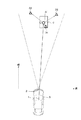
マッチング判定の概要を、図5に基づき説明する。例えば、図5に示すように、自車両Aの前方側に歩行者候補B’が存在するシーンにおいては、歩行者候補B’を中心点として方形や円形による許容誤差領域Cを設定する。そして、複数の対象物D1,D2,D3(レーザー検出体)から歩行者候補B’に最も近接する対象物D1を選択する。その後、許容誤差領域C内に対象物D1が存在する時間をカウントする。 An outline of the matching determination will be described with reference to FIG. For example, as shown in FIG. 5, in a scene where a pedestrian candidate B ′ is present on the front side of the host vehicle A, an allowable error region C is set as a square or a circle with the pedestrian candidate B ′ as a center point. Then, the object D1 closest to the pedestrian candidate B 'is selected from the plurality of objects D1, D2, D3 (laser detectors). Thereafter, the time during which the object D1 exists in the allowable error region C is counted.
ステップS8では、ステップS7でのマッチング判定に続き、マッチングが成立したか否かを判断する。YES(マッチング成立)の場合はステップS9へ進み、NO(マッチング不成立)の場合はステップS10へ進む。
ここで、ミリ波レーダー2からの選択された対象物D1が許容誤差領域C内に存在する状態であると判断された時間の積算値(カウント時間)が、マッチング判定時間(例えば、200msec)を経過すると「マッチング成立」とする。一方、ミリ波レーダー2からの選択された対象物D1が許容誤差領域C内に存在しない場合、或いは、ミリ波レーダー2からの選択された対象物D1が許容誤差領域C内に一時的に存在しても、積算値がマッチング時間に満たない間は、「マッチング不成立」とする。In step S8, following the matching determination in step S7, it is determined whether matching has been established. If YES (matching is established), the process proceeds to step S9. If NO (matching is not established), the process proceeds to step S10.
Here, the integrated value (count time) of the time when it is determined that the selected object D1 from the
ステップS9では、ステップS8でのマッチング成立であるとの判断に続き、フロントカメラユニット1により検出された歩行者候補B’を、制御対象の歩行者Bであると判定し、自動ブレーキ制御を継続し、エンドへ進む。
ここで、マッチング成立により制御対象の歩行者Bであると判定された場合、マッチング成立前であって、歩行者候補B’が検出されている間の自動ブレーキ制御での許容減速G(例えば、0.6G程度)よりも高い許容減速G(例えば、1.0G程度)とする。なお、自動ブレーキ制御則そのものについては、マッチング成立/不成立にかかわらず同じ制御則とすることで、自動ブレーキ制御を継続することになる。In step S9, following the determination that the matching is established in step S8, the pedestrian candidate B ′ detected by the
Here, if it is determined that matching is a pedestrian B to be controlled due to the establishment of matching, the allowable deceleration G (for example, automatic brake control) before matching is established and while the pedestrian candidate B ′ is detected (for example, Allowable deceleration G (for example, about 1.0 G) higher than about 0.6 G). As for the automatic brake control law itself, the automatic brake control is continued by setting the same control law regardless of whether the matching is established or not.
ステップS10では、ステップS8でのマッチング不成立であるとの判断に続き、マッチング判定を開始してから所定時間Tが経過したか否かを判断する。YES(所定時間Tが経過)の場合はステップS11へ進み、NO(所定時間Tが未経過)の場合はステップS7へ戻る。
ここで、「所定時間T」は、フロントカメラユニット1により検出された歩行者候補B’が実際に存在する歩行者である場合、制御対象の歩行者Bであると判定するのに要する時間に、余裕時間を加えた時間に設定する。In step S10, following the determination that matching is not established in step S8, it is determined whether or not a predetermined time T has elapsed since the start of the matching determination. If YES (predetermined time T has elapsed), the process proceeds to step S11. If NO (predetermined time T has not elapsed), the process returns to step S7.
Here, the “predetermined time T” is the time required to determine that the pedestrian candidate B ′ detected by the
ステップS11では、ステップS10での所定時間Tが経過であるとの判断に続き、自動ブレーキ制御を解除し、エンドへ進む。
即ち、マッチング判定を開始してから所定時間Tが経過してもマッチング不成立であると判断されると、フロントカメラユニット1により検出された歩行者候補B’が制御対象となる歩行者Bではないと判定する。自動ブレーキ制御の解除は、警報モードに入っているときは、警報を停止し、予備制動モードや本制動モードに入っているときは警報を停止すると共に、自動ブレーキ制御により付加されている制動力を解除する制御を行う。制動力解除制御は、急な車両挙動の変動を抑えて制動力を解除する制御であり、例えば、自動ブレーキ解除時の制動力を徐々に低下させる、或いは、自動ブレーキ解除時の制動力を所定時間保った後に徐々に低下させるような制御を行う。In step S11, following the determination that the predetermined time T has elapsed in step S10, the automatic brake control is canceled and the process proceeds to the end.
That is, if it is determined that the matching is not established even after the predetermined time T has elapsed since the start of the matching determination, the pedestrian candidate B ′ detected by the
次に、作用を説明する。
実施例1の電動車両の運転支援制御方法及び制御装置における作用を、「自動ブレーキ制御処理作用」、「自動ブレーキ制御作用」、「自動ブレーキ制御の特徴作用」に分けて説明する。Next, the operation will be described.
The operation in the driving support control method and control device for an electric vehicle according to the first embodiment will be described separately for “automatic brake control processing operation”, “automatic brake control operation”, and “characteristic operation of automatic brake control”.
[自動ブレーキ制御処理作用]
以下、図2のフローチャートに基づき、自動ブレーキ制御処理作用を説明する。
カメラ情報に基づく歩行者候補B’が検出されないときは、図2のフローチャートにおいて、ステップS1→ステップS2→ステップS3へと進む流れが繰り返される。そして、カメラ情報に基づく歩行者候補B’が検出されると、ステップS3からステップS4へ進み、ステップS4では、自動ブレーキ制御の実施が許可される。[Automatic brake control processing action]
Hereinafter, the automatic brake control processing operation will be described based on the flowchart of FIG.
When the pedestrian candidate B ′ based on the camera information is not detected, the flow from step S1 to step S2 to step S3 is repeated in the flowchart of FIG. And if pedestrian candidate B 'based on camera information is detected, it will progress from step S3 to step S4, and implementation of automatic brake control is permitted in step S4.
ステップS4において自動ブレーキ制御の実施が許可されると、ステップS4からステップS5へ進み、ステップS5では、接触予測時間TTCが、警報閾値TTC1以下であるか、予備制動閾値TTC2以下であるか、本制動閾値TTC3以下であるか否かが判断される。ステップS5においてTTC≦TTC1、又は、TTC≦TTC2、又は、TTC≦TTC3であると判断されると、ステップS6へ進み、ステップS6では、自動ブレーキ制御が開始される。ここで、TTC≦TTC1と判断されると、警報モード→予備制動モード→本制動モードと遷移する自動ブレーキ制御が開始される。TTC≦TTC2と判断されると、予備制動モード(警報)→本制動モード(警報)とモード遷移する自動ブレーキ制御が開始される。TTC≦TTC3と判断されると、本制動モード(警報)を実施する自動ブレーキ制御が開始される。 If the execution of the automatic brake control is permitted in step S4, the process proceeds from step S4 to step S5. In step S5, whether the predicted contact time TTC is equal to or less than the warning threshold value TTC1, or less than the preliminary braking threshold value TTC2, It is determined whether or not the braking threshold value is TTC3 or less. If it is determined in step S5 that TTC ≦ TTC1, or TTC ≦ TTC2, or TTC ≦ TTC3, the process proceeds to step S6. In step S6, automatic brake control is started. Here, when it is determined that TTC ≦ TTC1, automatic brake control that transitions from alarm mode → preliminary braking mode → main braking mode is started. When it is determined that TTC ≦ TTC2, automatic brake control is started in which the mode transition is made from the preliminary braking mode (alarm) to the main braking mode (alarm). When it is determined that TTC ≦ TTC3, automatic brake control for executing the present braking mode (warning) is started.
ステップS6において自動ブレーキ制御が開始されると、ステップS6からステップS7へ進み、ステップS7では、フロントカメラユニット1により検出された歩行者候補B’が、ミリ波レーダー2からの反射波により検出された対象物D1とマッチングするかどうかが比較判定される。そして、マッチング不成立であり、かつ、所定時間Tが未経過である間は、ステップS7→ステップS8→ステップS10へと進む流れが繰り返される。
When the automatic brake control is started in step S6, the process proceeds from step S6 to step S7. In step S7, the pedestrian candidate B ′ detected by the
ステップS7→ステップS8→ステップS10へと進む流れが繰り返されている間にステップS8において、マッチングが成立したと判断されると、ステップS8からステップS9→エンドへと進む。ステップS9においては、フロントカメラユニット1により検出された歩行者候補B’が、制御対象の歩行者Bであると判定され、許容減速Gを高くして自動ブレーキ制御が継続される。
If it is determined in step S8 that matching has been established while the flow from step S7 to step S8 to step S10 is repeated, the process proceeds from step S8 to step S9 to end. In step S9, it is determined that the pedestrian candidate B 'detected by the
一方、ステップS7→ステップS8→ステップS10へと進む流れが繰り返される間に所定時間Tを経過してしまうと、ステップS10からステップS11→エンドへと進む。ステップS11においては、フロントカメラユニット1により検出された歩行者候補B’が制御対象となる歩行者Bではないと判定され、自動ブレーキ制御が解除される。
On the other hand, if the predetermined time T elapses while the flow from step S7 to step S8 to step S10 is repeated, the process proceeds from step S10 to step S11 to end. In step S11, it is determined that the pedestrian candidate B 'detected by the
このように、自動ブレーキ制御処理では、フロントカメラユニット1からの画像信号に基づいて自車両Aの前方に歩行者候補B’が検出されると、検出された歩行者候補B’を制御対象として自動ブレーキ制御の実施を許可する(ステップS4)。そして、自動ブレーキ制御を開始した後、フロントカメラユニット1により検出された歩行者候補B’が、ミリ波レーダー2からの反射波により検出された対象物D1とマッチングするかどうかを比較判定する(ステップS7)。その後、所定時間Tが経過する前にマッチングが成立すると自動ブレーキ制御が継続され(ステップS9)、所定時間Tが経過するまでにマッチングが成立しないと自動ブレーキ制御が解除される(ステップS11)。
Thus, in the automatic brake control process, when the pedestrian candidate B ′ is detected in front of the host vehicle A based on the image signal from the
[自動ブレーキ制御作用]
まず、図5に示すように、自車両Aの予想進路上の前方位置を歩行者Bが横切ってきた場合の自動ブレーキ制御作用を、図6に基づいて説明する。なお、図6において、縦距離とは、自車両Aと歩行者候補B’(歩行者B)との図5の縦方向の距離をいい、縦距離=0が縦方向の接触距離になる。横距離とは、自車両Aと歩行者候補B’(歩行者B)との図5の横方向の距離をいい、横距離=0が横方向の接触距離になる。[Automatic brake control action]
First, as shown in FIG. 5, the automatic brake control action when the pedestrian B crosses the front position on the predicted course of the host vehicle A will be described based on FIG. In FIG. 6, the vertical distance refers to the vertical distance in FIG. 5 between the host vehicle A and the pedestrian candidate B ′ (pedestrian B), and the vertical distance = 0 is the vertical contact distance. The lateral distance is the lateral distance in FIG. 5 between the host vehicle A and the pedestrian candidate B ′ (pedestrian B), and the lateral distance = 0 is the lateral contact distance.
時刻t1にてフロントカメラユニット1からの画像信号に基づいて自車両Aの前方に存在する歩行者候補B’が検出されると、自動ブレーキ制御の実施が許可され、接触予測時間TTCの監視が始まる。時刻t2にて接触予測時間TTCが警報閾値TTC1以下になると、警報による自動ブレーキ制御が開始されると共に、検出された歩行者候補B’とミリ波レーダー2からの反射波により検出された対象物D1とマッチング判定が開始される。時刻t3にてマッチング成立であると判断されると(マッチングフラグON)、歩行者候補B’を制御対象として開始された自動ブレーキ制御が継続される。そして、時刻t4にて接触予測時間TTCが予備制動閾値TTC2以下になると、警報と予備制動による自動ブレーキ制御が開始される。さらに、時刻t5にて接触予測時間TTCが本制動閾値TTC3以下になると、警報と本制動による自動ブレーキ制御が開始される。そして、本制動により減速Gが高められて時刻t6になると、歩行者Bの直前にて自車両Aが停止する。
When the pedestrian candidate B ′ existing in front of the host vehicle A is detected based on the image signal from the
次に、自動ブレーキ制御の実施を早期に許可するメリットがあらわれるシーンとして、図7に基づいて、自車両Aの前方に停止している停止車両E(死角)から歩行者Bが自車両Aの予想進路上に飛び出してくるシーンでの自動ブレーキ作用を説明する。 Next, as a scene where there is a merit of permitting early execution of automatic brake control, a pedestrian B of the own vehicle A from a stop vehicle E (dead angle) stopped in front of the own vehicle A based on FIG. The automatic braking action in a scene that pops out on the expected course will be described.
停止車両Eから歩行者Bが自車両Aの予想進路上に飛び出してくるシーンにおいては、フロントカメラユニット1からの情報に基づく歩行者検出を行うと、形状認識により歩行者検出が可能である。しかし、ミリ波レーダー2からの情報で対象物検出(歩行者検出)を行うと、図7の右部分に示すように、停止車両Eと歩行者Bとが一体の対象物として検出されるため、停止車両Eと歩行者Bとの間隔が十分に確保されるまで待った後、歩行者検出が可能である。
In a scene where the pedestrian B jumps out from the stop vehicle E onto the expected course of the host vehicle A, when pedestrian detection is performed based on information from the
よって、マッチング成立を待って自動ブレーキ制御を開始すると、図7に示すように、例えば、時刻t2になってから予備制動が開始されるというように、自動ブレーキ制御の開始が遅れる。これに対し、フロントカメラユニット1からの情報で歩行者候補B’が検出されると、比較判定結果(マッチング成立)を待たずに自動ブレーキ制御の実施を許可すると、例えば、時刻t0にて自動ブレーキ制御の実施が許可され、時刻t1になると予備制動が開始されるというように、自動ブレーキ制御の開始が早期化する。
Therefore, when the automatic brake control is started after the matching is established, the start of the automatic brake control is delayed, for example, as shown in FIG. 7, the preliminary braking is started after time t2. On the other hand, when the pedestrian candidate B ′ is detected from the information from the
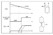
次に、フロントカメラユニット1とミリ波レーダー2の検出情報を比較判定するメリットがあらわれるシーンとして、図8に基づいて、自車両Aの前方の予想進路上に存在する前方車両Fから白煙状排気ガスGを出しているシーンでの自動ブレーキ作用を説明する。
Next, as a scene where the merit of comparing and detecting the detection information of the
前方車両Fから白煙状排気ガスGを出しているシーンでは、フロントカメラユニット1からの情報に基づく対象物検出の場合、図8の右部分に示すように、形状認識であることにより白煙状排気ガスGを歩行者と誤検出することがある。一方、ミリ波レーダー2からの情報で対象物検出を行う場合は、照射されたミリ波の反射波を用いるため、白煙状排気ガスGを歩行者と誤検出することはない。
In the scene where white smoke-like exhaust gas G is emitted from the front vehicle F, in the case of object detection based on information from the
よって、フロントカメラユニット1からの情報で歩行者候補B’が検出され、接触予測時間TTCが予備制動閾値TTC2以下になると時刻t1にて予備制動が開始されても、ミリ波レーダー2が対象物を検出せず、マッチングが不成立のままで所定時間Tを経過する。このため、時刻t2にて自動ブレーキ制御が解除され、その後、予備制動により加えられた制動力を徐々に低下させ、時刻t3で実際の制動力解除が達成される。
Therefore, when the pedestrian candidate B ′ is detected from the information from the
[自動ブレーキ制御の特徴作用]
実施例1では、フロントカメラユニット1からの画像信号に基づいて自車両Aの前方に存在する対象物が歩行者候補B’であると検出されると、検出された歩行者候補B’を制御対象として自動ブレーキ制御の実施を許可する。その後、フロントカメラユニット1により検出された歩行者候補B’が、ミリ波レーダー2からの反射波により検出された対象物とマッチングするかどうかを比較判定する。そして、比較判定結果(マッチング判定結果)に基づき自動ブレーキ制御の実施を継続するか否かを決定する。[Characteristics of automatic brake control]
In the first embodiment, when the object existing in front of the host vehicle A is detected based on the image signal from the
即ち、フロントカメラユニット1とミリ波レーダー2を用いて自車両の前方に存在する歩行者Bを検出する場合、フロントカメラユニット1とミリ波レーダー2には、下記に述べるような長所と短所がある。
That is, when the
フロントカメラユニット1は、形状認識により人間の形をした動くものを単独で歩行者として見分けて判定することが可能であるという長所を持つ。しかし、悪天候であるとき、前方から逆光があるとき、対象物が背景の色合いに溶け込んでいるとき、路面標示があるとき、排気ガスの煙が固まり状態のとき等において、対象物を誤検出することがあるという短所を持つ。
The
一方、ミリ波レーダー2は、かなり遠方の対象物を検出できると共に、悪天候に比較的強く、逆光も問題にしないことで、自車両の前方に対象物が存在するときに対象物認識性がフロントカメラユニット1よりも高いという長所を持つ。しかし、対象物が先行車であるが歩行者であるかを見分けることが事実上できないという短所がある。
On the other hand, the millimeter-
上記フロントカメラユニット1とミリ波レーダー2の長所と短所に着目し、形状認識により単独で歩行者検出が可能なカメラからの情報で歩行者候補B’が検出されると、比較判定結果を待たず、先出しにより自動ブレーキ制御の実施を許可する。その後、自車両Aの前方に歩行者Bが存在するときに対象物認識性がフロントカメラユニット1より高いミリ波レーダー2からの情報を比較判定に用い、自動ブレーキ制御の実施を継続するか否かを決定し、カメラ検出結果の信頼性有無をバックアップする。
Focusing on the advantages and disadvantages of the
よって、フロントカメラユニット1により歩行者候補B’が検出されると、直ちに自動ブレーキ制御の実施が許可される。このため、フロントカメラユニット1とミリ波レーダー2の双方による歩行者Bの比較判定結果を待つ場合に比べ、自動ブレーキ制御の開始タイミングが早期になる。その後、フロントカメラユニット1により検出された歩行者候補B’が、ミリ波レーダー2からの反射波により検出された対象物とマッチングするかどうかが比較判定され、比較判定結果に基づき自動ブレーキ制御の実施を継続するか否かが決定される。このため、歩行者Bの誤判定防止機能が確保される。
Therefore, when the pedestrian candidate B 'is detected by the
実施例1では、フロントカメラユニット1により検出された歩行者候補B’の方向/距離による位置情報を中心点とする許容誤差領域Cを設定し、ミリ波レーダー2からの反射波により検出された複数の対象物のうち歩行者候補B’に最も近い対象物D1の方向/距離による位置情報を比較判定に用いる。ミリ波レーダー2により検出された位置情報が、許容誤差領域Cの範囲内で判定時間だけマッチングすると、フロントカメラユニット1により検出された歩行者候補B’を、制御対象の歩行者Bであると判定する。
In the first embodiment, an allowable error region C is set with the position information based on the direction / distance of the pedestrian candidate B ′ detected by the
例えば、2つの位置情報を対比し、2つの位置が一致することを条件としてフロントカメラユニット1により検出された歩行者候補B’を歩行者Bであると判定すると、判定精度が確保されるものの歩行者判定に時間を要する。一方、2つの位置情報が許容誤差領域に入るだけで、フロントカメラユニット1により検出された歩行者候補B’を歩行者Bであると判定すると、歩行者判定の応答性が確保されるものの、判定精度が低下する。
For example, when comparing two pieces of position information and determining that the pedestrian candidate B ′ detected by the
これに対し、制御対象の歩行者Bを比較判定するとき、許容誤差領域C内に判定時間だけ存在するという比較判定手法とすることで、歩行者判定精度の確保と、歩行者判定応答性の向上と、の両立が達成される。 On the other hand, when comparing and determining the pedestrian B to be controlled, a comparison determination method in which the determination error exists within the allowable error region C ensures the pedestrian determination accuracy and the pedestrian determination responsiveness. Improvement and compatibility are achieved.
実施例1では、運転支援制御の実施が許可されているとき、警報と自動ブレーキ制御による運転支援制御を実施する。歩行者Bとの接触可能性が第1段階(TTC≦TTC1)になると警報による運転支援を開始し、第1段階よりも歩行者Bとの接触可能性が高い第2段階(TTC≦TTC2)になると警報に加えて緩ブレーキによる予備制動を開始する。そして、第2段階よりも歩行者との接触可能性が高い第3段階(TTC≦TTC3)になると警報に加えて急ブレーキによる本制動を開始する。 In the first embodiment, when the execution of the driving support control is permitted, the driving support control by the alarm and the automatic brake control is performed. When the possibility of contact with pedestrian B reaches the first stage (TTC ≤ TTC1), driving assistance by warning is started, and the second stage with higher possibility of contact with pedestrian B than the first stage (TTC ≤ TTC2) When it becomes, in addition to the alarm, preliminary braking by slow braking is started. And if it becomes the 3rd step (TTC <= TTC3) where contact possibility with a pedestrian is higher than the 2nd step, in addition to a warning, the main braking by sudden braking will be started.
即ち、警報は、自車両Aと歩行者Bとの接触可能性があることを運転者に対し聴覚支援や視覚支援により知らせる機能を持つ。緩ブレーキによる予備制動は、自車両Aと歩行者Bとの接触可能性があることを運転者に対し体感支援により知らせる機能を持つと共に、急ブレーキによる本制動に入ると停車可能なように予備的に減速する機能を持つ。急ブレーキによる本制動は、自車両Aと歩行者Bとが接触に至る前に自車両Aを減速停車させて接触を回避する機能を持つ。 In other words, the alarm has a function of notifying the driver that there is a possibility of contact between the own vehicle A and the pedestrian B by auditory assistance or visual assistance. Preliminary braking with a slow brake has a function of notifying the driver that there is a possibility of contact between the own vehicle A and a pedestrian B by providing sensation support, and is reserved so that the vehicle can be stopped when entering the main braking by sudden braking. Has the ability to slow down. The main braking by the sudden brake has a function of decelerating and stopping the own vehicle A before the own vehicle A and the pedestrian B come into contact to avoid contact.
従って、警報と自動ブレーキ制御による運転支援制御を実施するとき、運転者に対する段階的な運転支援により、運転者によるブレーキ操作やステアリング操作による接触回避を促し、自動ブレーキ制御の作動頻度を低減する。加えて、運転者によるブレーキ操作を待てない状況下では、自動的に作動する予備制動→本制動、或いは、本制動により、自車両Aと歩行者Bとの接触回避可能性が高められる。つまり、自動ブレーキ制御の開始タイミング早期化と段階的な運転支援とが相俟って、自車両Aと歩行者Bとの接触回避が達成されるシーンが拡大される。 Therefore, when the driving support control by the alarm and the automatic brake control is performed, the driver avoids the contact by the brake operation or the steering operation by the stepwise driving support to the driver, and the operation frequency of the automatic brake control is reduced. In addition, in a situation where the driver cannot wait for the brake operation, the possibility of avoiding contact between the own vehicle A and the pedestrian B is enhanced by automatically acting preliminary braking → main braking or main braking. That is, the scene where the contact avoidance between the host vehicle A and the pedestrian B is achieved is expanded by combining the start timing of the automatic brake control and the stepwise driving support.
実施例1では、フロントカメラユニット1による歩行者候補B’の検出からミリ波レーダー2を加えた比較判定による歩行者Bの判定へ移行すると、自動ブレーキ制御の許可減速Gを、歩行者候補B’が検出されている間の許可減速Gよりも高くする。
即ち、歩行者判定の信頼度は、フロントカメラユニット1による歩行者候補B’を検出しているだけのときよりも、比較判定による歩行者Bを判定しているときの方が高い。そして、歩行者候補B’を検出しているとき、その後、比較判定により歩行者候補B’が歩行者でないと判定されると、自動ブレーキ制御を途中で解除することになる。
従って、フロントカメラユニット1による歩行者候補B’を検出している間は、自動ブレーキ制御で許可される減速Gを抑えておくことで、自車両Aを減速させつつも自動ブレーキ制御の解除に備えておくことができる。そして、比較判定による歩行者Bが判定されると、自動ブレーキ制御で許可される減速Gを高くすることで、自車両が停止するまでの必要距離が短縮され、例えば、歩行者の飛び出し等の緊急時に高速域まで拡大した自動ブレーキ制御の作動が確保される。In the first embodiment, when the detection of the pedestrian candidate B ′ by the
That is, the reliability of the pedestrian determination is higher when the pedestrian B is determined by the comparison determination than when the pedestrian candidate B ′ is detected only by the
Therefore, while the pedestrian candidate B ′ is detected by the
次に、効果を説明する。
実施例1における電動車両の運転支援制御方法及び制御装置にあっては、下記に列挙する効果が得られる。Next, the effect will be described.
In the driving support control method and control device for an electric vehicle in the first embodiment, the effects listed below can be obtained.
(1) 自車両Aの前方情報を取得する外界認識センサを備え、外界認識センサにより歩行者Bが検出されると、自車両Aが歩行者Bへ接触するのを回避する運転支援制御(自動ブレーキ制御)を実施する。
この車両の運転支援制御方法において、外界認識センサとして、カメラ(フロントカメラユニット1)とレーダー(ミリ波レーダー2)を備える。
カメラ(フロントカメラユニット1)からの画像信号に基づいて自車両Aの前方に存在する対象物が歩行者候補B’であると検出されると、検出された歩行者候補B’を制御対象として運転支援制御(自動ブレーキ制御)の実施を許可する。
その後、カメラ(フロントカメラユニット1)により検出された歩行者候補B’が、レーダー(ミリ波レーダー2)からの反射波により検出された対象物D1とマッチングするかどうかを比較判定し、比較判定結果に基づき運転支援制御(自動ブレーキ制御)の実施を継続するか否かを決定する(図2)。
このため、走行中、歩行者Bの誤判定防止機能を確保しつつ、運転支援制御(自動ブレーキ制御)を開始する開始タイミングの早期化を達成する車両の運転支援制御方法を提供することができる。(1) Driving assistance control (automatic) that includes an external recognition sensor that acquires forward information of the own vehicle A, and that prevents the own vehicle A from contacting the pedestrian B when the pedestrian B is detected by the external recognition sensor. Brake control).
In this vehicle driving support control method, a camera (front camera unit 1) and a radar (millimeter wave radar 2) are provided as external recognition sensors.
When it is detected that an object existing ahead of the host vehicle A is a pedestrian candidate B ′ based on an image signal from the camera (front camera unit 1), the detected pedestrian candidate B ′ is set as a control target. Allows execution of driving support control (automatic brake control).
Thereafter, it is determined whether or not the pedestrian candidate B ′ detected by the camera (front camera unit 1) matches the object D1 detected by the reflected wave from the radar (millimeter wave radar 2). Based on the result, it is determined whether or not to continue driving support control (automatic brake control) (FIG. 2).
For this reason, it is possible to provide a vehicle driving support control method that achieves early start timing for starting driving support control (automatic brake control) while ensuring a function for preventing erroneous determination of pedestrian B during traveling. .
(2) 比較判定では、カメラ(フロントカメラユニット1)により判定された歩行者候補B’の方向/距離による位置情報を中心点とする許容誤差領域Cを設定する。
レーダー(ミリ波レーダー2)からの反射波により検出された複数の対象物のうち歩行者候補B’に最も近い対象物D1の方向/距離による位置情報が、許容誤差領域C内で所定時間だけマッチングすると、カメラ(フロントカメラユニット1)により検出された歩行者候補B’を、制御対象の歩行者Bであると判定する(図5)。
このため、(1)の効果に加え、制御対象の歩行者Bを比較判定するとき、歩行者判定精度の確保と、歩行者判定応答性の向上と、の両立を達成することができる。(2) In the comparison determination, an allowable error region C is set with the position information based on the direction / distance of the pedestrian candidate B ′ determined by the camera (front camera unit 1) as the center point.
Position information based on the direction / distance of the object D1 closest to the pedestrian candidate B ′ among the plurality of objects detected by the reflected wave from the radar (millimeter wave radar 2) is within the allowable error region C for a predetermined time. If it matches, it will determine with pedestrian candidate B 'detected by the camera (front camera unit 1) being the pedestrian B of a control object (FIG. 5).
For this reason, in addition to the effect of (1), when comparing and determining the pedestrian B to be controlled, both of ensuring the pedestrian determination accuracy and improving the pedestrian determination responsiveness can be achieved.
(3) 運転支援制御は、運転支援制御の実施が許可されているとき、警報と自動ブレーキ制御により実施するものであり、歩行者Bとの接触可能性が第1段階(TTC≦TTC1)になると警報による運転支援を開始する。第1段階よりも歩行者Bとの接触可能性が高い第2段階(TTC≦TTC2)になると警報に加えて緩ブレーキによる予備制動を開始する。第2段階よりも歩行者との接触可能性が高い第3段階(TTC≦TTC3)になると警報に加えて急ブレーキによる本制動を開始する(図4)。
このため、(1)又は(2)の効果に加え、警報と自動ブレーキ制御による運転支援制御を実施するとき、運転者に対する段階的な運転支援により、自動ブレーキ制御の作動頻度を低減できると共に、自車両Aと歩行者Bとの接触回避が達成されるシーンを拡大することができる。(3) Driving support control is implemented by warning and automatic brake control when driving support control is permitted, and the possibility of contact with pedestrian B is in the first stage (TTC ≦ TTC1). Then, start driving support by warning. In the second stage (TTC ≦ TTC2) in which the possibility of contact with the pedestrian B is higher than that in the first stage, preliminary braking by the slow brake is started in addition to the alarm. In the third stage (TTC ≦ TTC3) where the possibility of contact with a pedestrian is higher than in the second stage, in addition to the alarm, the main braking by the sudden brake is started (FIG. 4).
For this reason, in addition to the effect of (1) or (2), when performing driving support control by alarm and automatic brake control, the operation frequency of automatic brake control can be reduced by stepwise driving support for the driver, The scene where the contact avoidance between the own vehicle A and the pedestrian B is achieved can be enlarged.
(4) 自動ブレーキ制御は、カメラ(フロントカメラユニット1)による歩行者候補B’の検出からレーダー(ミリ波レーダー2)を加えた比較判定による歩行者Bの判定へ移行すると、自動ブレーキ制御の許可減速Gを、歩行者候補B’が検出されている間の許可減速Gよりも高くする(図2)。
このため、(3)の効果に加え、歩行者候補B’が検出されている間は自動ブレーキ制御の解除に備えつつも、歩行者Bが判定されると、高速域まで拡大した自動ブレーキ制御の作動を確保することができる。(4) When automatic brake control shifts from the detection of pedestrian candidate B ′ by the camera (front camera unit 1) to the determination of pedestrian B by comparison determination with the addition of radar (millimeter wave radar 2), automatic brake control The permitted deceleration G is set higher than the permitted deceleration G while the pedestrian candidate B ′ is detected (FIG. 2).
For this reason, in addition to the effect of (3), while the pedestrian candidate B ′ is detected, the automatic brake control is expanded to the high speed range when the pedestrian B is determined while preparing for the release of the automatic brake control. Can be ensured.
(5) 自車両Aの前方情報を取得する外界認識センサと、外界認識センサにより歩行者Bが判定されると、自車両Aが歩行者Bへ接触するのを回避する運転支援制御(自動ブレーキ制御)を実施する運転支援コントローラ3と、を有する。
この車両の運転支援制御装置において、外界認識センサとして、カメラ(フロントカメラユニット1)とレーダー(ミリ波レーダー2)を備える。
運転支援コントローラ3は、カメラ(フロントカメラユニット1)からの画像信号に基づいて自車両Aの前方に存在する対象物が歩行者候補B’であると判定されると、判定された歩行者候補B’を制御対象として運転支援制御(自動ブレーキ制御)の実施を許可する。
その後、カメラ(フロントカメラユニット1)により判定された歩行者候補B’が、レーダー(ミリ波レーダー2)からの反射波により検出された対象物D1とマッチングするかどうかを比較判定し、比較判定結果に基づき運転支援制御(自動ブレーキ制御)の実施を継続するか否かを決定する制御処理を行う(図2)。
このため、走行中、歩行者Bの誤判定防止機能を確保しつつ、運転支援制御(自動ブレーキ制御)を開始する開始タイミングの早期化を達成する車両の運転支援制御装置を提供することができる。(5) Driving assistance control (automatic brake) that avoids the vehicle A coming into contact with the pedestrian B when the pedestrian B is determined by the outside recognition sensor that acquires the front information of the vehicle A and the outside recognition sensor. And a driving
In this vehicle driving support control device, a camera (front camera unit 1) and a radar (millimeter wave radar 2) are provided as external recognition sensors.
When the driving
Thereafter, it is determined whether the pedestrian candidate B ′ determined by the camera (front camera unit 1) matches the object D1 detected by the reflected wave from the radar (millimeter wave radar 2). Based on the result, a control process is performed to determine whether or not to continue driving support control (automatic brake control) (FIG. 2).
For this reason, during driving | running | working, the driving assistance control apparatus of the vehicle which achieves early start timing which starts driving assistance control (automatic brake control), ensuring the erroneous determination prevention function of the pedestrian B can be provided. .
以上、本発明の車両の運転支援制御方法及び制御装置を実施例1に基づき説明してきたが、具体的な構成については、この実施例1に限られるものではなく、請求の範囲の各請求項に係る発明の要旨を逸脱しない限り、設計の変更や追加等は許容される。 The vehicle driving support control method and the control apparatus of the present invention have been described based on the first embodiment. However, the specific configuration is not limited to the first embodiment, and each claim of the claims Design changes and additions are permitted without departing from the spirit of the invention.
実施例1では、カメラとして、シングルカメラ(単眼カメラ)であるフロントカメラユニット1を用いる例を示した。しかし、カメラとしては、一対のフロントカメラによるステレオカメラを用いる例であっても良い。
In Example 1, the example using the
実施例1では、レーダーとして、車両前方に向かってミリ波を照射するミリ波レーダー2を用いる例を示した。しかし、レーダーとしては、赤外線レーザーレーダーを用いる例であっても良いし、ミリ波レーダーと赤外線レーザーレーダーを併用する例であっても良い。
In Example 1, the example which uses the
実施例1では、運転支援制御として、警報を含む自動ブレーキ制御の例を示した。しかし、運転支援制御としては、自車両の前方に存在する歩行者を制御対象とする制御であれば、制動やステアリングにより歩行者を迂回するように自車両をコントロールすることで接触を回避する他の運転支援制御の例であっても良い。 In the first embodiment, an example of automatic brake control including an alarm is shown as the driving support control. However, as driving support control, if the control target is a pedestrian existing in front of the host vehicle, other than avoiding contact by controlling the host vehicle to bypass the pedestrian by braking or steering. This may be an example of driving support control.
実施例1では、比較判定として、フロントカメラユニット1により判定された歩行者候補B’の方向/距離による位置情報を中心点とする許容誤差領域Cを設定するマッチング判定の例を示した。しかし、比較判定としては、許容誤差領域を設定することなく、フロントカメラユニットにより判定された歩行者候補の方向/距離による位置情報と、ミリ波レーダーからの反射波により検出された対象物との許容誤差範囲内で一致するかどうかを判断する例であっても良い。
In the first embodiment, as the comparison determination, an example of the matching determination in which the allowable error region C having the center point as the position information based on the direction / distance of the pedestrian candidate B ′ determined by the
実施例1では、自動ブレーキ制御として、警報モード→予備制動モード→本制動モードとモード遷移する制御例を示した。しかし、自動ブレーキ制御としては、警報モードと制動モードによる例であっても良い。 In the first embodiment, as the automatic brake control, the control example in which the mode transition is performed from alarm mode → preliminary braking mode → main braking mode is shown. However, the automatic brake control may be an example using an alarm mode and a braking mode.
実施例1では、自動ブレーキ制御の実施を許可した後、自動ブレーキ制御を開始するのと同時にマッチング判定を開始する例を示した。しかし、マッチング判定の開始を自動ブレーキ制御の開始とリンクさせることなく、自動ブレーキ制御の実施を許可した直後からマッチング判定を開始するような例としても良い。 In the first embodiment, after the execution of the automatic brake control is permitted, the matching determination is started simultaneously with the start of the automatic brake control. However, the matching determination may be started immediately after the execution of the automatic brake control is permitted without linking the start of the matching determination with the start of the automatic brake control.
実施例1では、本発明の運転支援制御方法及び制御装置を、自動ブレーキ制御システム及び電動型制御ブレーキユニット4を搭載した電動車両に適用する例を示した。しかし、本発明の運転支援制御方法及び制御装置は、自動ブレーキ制御システム以外のブレーキ制御やステアリング制御や駆動源制御等により自車両と歩行者の接触を回避する他の運転支援制御を行うシステムを搭載した車両に対しても適用することができる。さらに、電動車両以外のエンジン車に適用することもでき、この場合、ブレーキアクチュエータとして、例えば、ABS/VDCアクチュエータの電動ポンプモータを用いる。要するに、走行中、車両前方に存在する歩行者を認識し、自車両と歩行者の接触を回避する車両の運転支援制御方法及び制御装置であれば適用できる。
In the first embodiment, the driving support control method and the control device of the present invention are applied to an electric vehicle equipped with an automatic brake control system and an electric
本出願は、2016年1月22日に日本国特許庁に出願された特願2016−011032に基づいて優先権を主張し、その全ての開示は完全に本明細書で参照により組み込まれる。 This application claims priority based on Japanese Patent Application No. 2006-011032 filed with the Japan Patent Office on January 22, 2016, the entire disclosure of which is fully incorporated herein by reference.
Claims (5)
前記外界認識センサとして、カメラとレーダーを備え、
前記カメラからの画像信号に基づいて自車両の前方に存在する対象物が歩行者候補であると検出されると、検出された歩行者候補を制御対象として前記運転支援制御を開始し、
その後、前記カメラにより検出された歩行者候補が、前記レーダーからの反射波により検出された対象物とマッチングするかどうかを比較判定し、マッチングが成立すると前記運転支援制御を継続し、マッチングが成立しないと前記運転支援制御を解除する
ことを特徴とする車両の運転支援制御方法。Driving support control for a vehicle that includes an external recognition sensor that acquires front information of the host vehicle, and that performs driving support control that prevents the host vehicle from contacting the pedestrian when a pedestrian is detected by the external recognition sensor In the method
As the outside world recognition sensor, a camera and a radar are provided,
When it is detected that an object existing ahead of the host vehicle is a pedestrian candidate based on an image signal from the camera, the driving support control is started using the detected pedestrian candidate as a control target,
After that, it is determined whether or not the pedestrian candidate detected by the camera matches the object detected by the reflected wave from the radar, and if the matching is established, the driving support control is continued and the matching is established. If not, the driving support control method of the vehicle is canceled.
前記比較判定では、前記カメラにより検出された歩行者候補の方向/距離による位置情報を中心点とする許容誤差領域を設定し、
前記レーダーからの反射波により検出された複数の対象物のうち前記歩行者候補に最も近い対象物の方向/距離による位置情報が、前記許容誤差領域内で所定時間だけマッチングすると、前記カメラにより検出された歩行者候補を、制御対象の歩行者であると判定する
ことを特徴とする車両の運転支援制御方法。The vehicle driving support control method according to claim 1,
In the comparison determination, an allowable error region is set with the position information based on the direction / distance of the pedestrian candidate detected by the camera as a center point,
When the position information based on the direction / distance of the object closest to the pedestrian candidate among the plurality of objects detected by the reflected wave from the radar is matched within the allowable error region for a predetermined time, the camera detects it. The vehicle driving support control method, wherein the determined pedestrian candidate is determined to be a pedestrian to be controlled.
前記運転支援制御は、運転支援制御の実施が許可されているとき、警報と自動ブレーキ制御により実施するものであり、
歩行者との接触可能性が第1段階になると前記警報による運転支援を開始し、前記第1段階よりも歩行者との接触可能性が高い第2段階になると前記警報に加えて緩ブレーキによる予備制動を開始し、前記第2段階よりも歩行者との接触可能性が高い第3段階になると前記警報に加えて急ブレーキによる本制動を開始する
ことを特徴とする車両の運転支援制御方法。In the vehicle driving support control method according to claim 1 or 2,
The driving support control is performed by warning and automatic brake control when the driving support control is permitted.
When the possibility of contact with a pedestrian reaches the first stage, driving assistance by the warning is started, and when the second stage has a higher possibility of contact with a pedestrian than the first stage, in addition to the warning, a gentle brake is used. Preliminary braking is started, and main braking by sudden braking is started in addition to the alarm when the third stage has a higher possibility of contact with a pedestrian than in the second stage. .
前記自動ブレーキ制御は、前記カメラによる歩行者候補の判定から前記レーダーを加えた比較判定による歩行者の判定へ移行すると、前記自動ブレーキ制御での許可減速Gを、前記歩行者候補が検出されている間の許可減速Gよりも高くする
ことを特徴とする車両の運転支援制御方法。In the vehicle driving support control method according to claim 3,
When the automatic brake control shifts from the determination of the pedestrian candidate by the camera to the determination of the pedestrian by the comparison determination including the radar, the permitted deceleration G in the automatic brake control is detected as the pedestrian candidate. A driving support control method for a vehicle, characterized in that the vehicle is set to be higher than the permitted deceleration G while the vehicle is on.
前記外界認識センサにより歩行者が判定されると、自車両が歩行者へ接触するのを回避する運転支援制御を実施する運転支援コントローラと、
を有する車両の運転支援制御装置において、
前記外界認識センサとして、カメラとレーダーを備え、
前記運転支援コントローラは、前記カメラからの画像信号に基づいて自車両の前方に存在する対象物が歩行者候補であると判定されると、判定された歩行者候補を制御対象として前記運転支援制御を開始し、
その後、前記カメラにより検出された歩行者候補が、前記レーダーからの反射波により検出された対象物とマッチングするかどうかを比較判定し、マッチングが成立すると前記運転支援制御を継続し、マッチングが成立しないと前記運転支援制御を解除する制御処理を行う
ことを特徴とする車両の運転支援制御装置。An external recognition sensor for acquiring front information of the host vehicle;
When a pedestrian is determined by the outside world recognition sensor, a driving assistance controller that implements driving assistance control for avoiding that the host vehicle contacts the pedestrian;
In a vehicle driving support control device having
As the outside world recognition sensor, a camera and a radar are provided,
When it is determined that an object existing ahead of the host vehicle is a pedestrian candidate based on an image signal from the camera, the driving support controller uses the determined pedestrian candidate as a control target and performs the driving support control. Start
After that, it is determined whether or not the pedestrian candidate detected by the camera matches the object detected by the reflected wave from the radar, and if the matching is established, the driving support control is continued and the matching is established. If not, a control process for canceling the driving support control is performed.
Applications Claiming Priority (3)
| Application Number | Priority Date | Filing Date | Title |
|---|---|---|---|
| JP2016011032 | 2016-01-22 | ||
| JP2016011032 | 2016-01-22 | ||
| PCT/JP2016/085130 WO2017126226A1 (en) | 2016-01-22 | 2016-11-28 | Vehicle driving assist control method and control device |
Publications (2)
| Publication Number | Publication Date |
|---|---|
| JP6358409B2 true JP6358409B2 (en) | 2018-07-25 |
| JPWO2017126226A1 JPWO2017126226A1 (en) | 2018-09-06 |
Family
ID=59362276
Family Applications (1)
| Application Number | Title | Priority Date | Filing Date |
|---|---|---|---|
| JP2017562459A Active JP6358409B2 (en) | 2016-01-22 | 2016-11-28 | Vehicle driving support control method and control device |
Country Status (9)
| Country | Link |
|---|---|
| US (1) | US10576972B2 (en) |
| EP (1) | EP3407327B1 (en) |
| JP (1) | JP6358409B2 (en) |
| CN (1) | CN108475469B (en) |
| BR (1) | BR112018014840B1 (en) |
| MX (1) | MX2018008919A (en) |
| MY (1) | MY188558A (en) |
| RU (1) | RU2687196C1 (en) |
| WO (1) | WO2017126226A1 (en) |
Cited By (1)
| Publication number | Priority date | Publication date | Assignee | Title |
|---|---|---|---|---|
| KR102243244B1 (en) * | 2019-08-26 | 2021-04-23 | 엘지전자 주식회사 | Method and apparatus for controlling by emergency step in autonomous driving system |
Families Citing this family (35)
| Publication number | Priority date | Publication date | Assignee | Title |
|---|---|---|---|---|
| JP6569523B2 (en) * | 2015-12-25 | 2019-09-04 | 株式会社デンソー | Driving support device |
| KR101996420B1 (en) * | 2016-12-30 | 2019-10-01 | 현대자동차주식회사 | Method and apparatus for pedestrian collision mitigation |
| KR101996419B1 (en) * | 2016-12-30 | 2019-07-04 | 현대자동차주식회사 | Sensor integration based pedestrian detection and pedestrian collision prevention apparatus and method |
| KR101996418B1 (en) * | 2016-12-30 | 2019-07-04 | 현대자동차주식회사 | Sensor integration based pedestrian detection and pedestrian collision prevention apparatus and method |
| JP6859720B2 (en) * | 2017-01-24 | 2021-04-14 | いすゞ自動車株式会社 | Vehicle control device and management system |
| JP6953922B2 (en) * | 2017-09-06 | 2021-10-27 | 株式会社デンソー | Vehicle driving support device and vehicle driving support method |
| JP6590300B2 (en) * | 2017-10-03 | 2019-10-16 | マツダ株式会社 | Driving assistance device |
| KR102552490B1 (en) * | 2018-01-03 | 2023-07-06 | 현대자동차주식회사 | Image processing apparatus and method for vehicle |
| JP2019172032A (en) * | 2018-03-28 | 2019-10-10 | ダイハツ工業株式会社 | Automatic braking device |
| CN109435847A (en) * | 2018-09-14 | 2019-03-08 | 常州智行科技有限公司 | A kind of vehicle anti-rear collision method for early warning based on camera and millimetre-wave radar |
| US20220404488A1 (en) * | 2018-10-01 | 2022-12-22 | Kpit Technologies Limited | Perception sensors based fusion system for vehicle control and method thereof |
| JPWO2020116204A1 (en) * | 2018-12-07 | 2021-10-21 | ソニーセミコンダクタソリューションズ株式会社 | Information processing device, information processing method, program, mobile control device, and mobile |
| CN109581358B (en) * | 2018-12-20 | 2021-08-31 | 奇瑞汽车股份有限公司 | Obstacle recognition method, obstacle recognition device and storage medium |
| CN109649360B (en) * | 2019-01-18 | 2024-01-30 | 佛山职业技术学院 | Method and system for avoiding pedestrians by automobile |
| DE102019107412B3 (en) * | 2019-03-22 | 2020-07-09 | Zf Active Safety Gmbh | Control system and control method for driving a motor vehicle |
| CN111698459B (en) * | 2019-04-26 | 2021-07-27 | 广东邦盛北斗科技股份公司 | Real-time analysis method for object parameters |
| CN110068818A (en) * | 2019-05-05 | 2019-07-30 | 中国汽车工程研究院股份有限公司 | The working method of traffic intersection vehicle and pedestrian detection is carried out by radar and image capture device |
| CN110333725B (en) * | 2019-07-26 | 2022-05-20 | 爱驰汽车有限公司 | Method, system, equipment and storage medium for automatically driving to avoid pedestrians |
| JP2021024539A (en) * | 2019-08-09 | 2021-02-22 | トヨタ自動車株式会社 | Drive support device |
| US11375179B1 (en) * | 2019-11-08 | 2022-06-28 | Tanzle, Inc. | Integrated display rendering |
| CN110969855A (en) * | 2019-12-13 | 2020-04-07 | 长沙莫之比智能科技有限公司 | Traffic flow monitoring system based on millimeter wave radar |
| JP7290104B2 (en) * | 2019-12-23 | 2023-06-13 | 株式会社デンソー | SELF-LOCATION ESTIMATING DEVICE, METHOD AND PROGRAM |
| US11590891B2 (en) | 2020-01-16 | 2023-02-28 | Caterpillar Paving Products Inc. | Control system for a machine |
| JP7259778B2 (en) * | 2020-01-31 | 2023-04-18 | トヨタ自動車株式会社 | Vehicles and automated driving systems |
| CN111739338A (en) * | 2020-05-07 | 2020-10-02 | 智慧互通科技有限公司 | Parking management method and system based on multiple types of sensors |
| JP7473277B2 (en) * | 2020-07-07 | 2024-04-23 | 株式会社Subaru | Vehicle driving control device |
| CN111795837A (en) * | 2020-07-20 | 2020-10-20 | 重庆渝微电子技术研究院有限公司 | Simple advanced intelligent auxiliary driving system detection system and method |
| CN111814769A (en) * | 2020-09-02 | 2020-10-23 | 深圳市城市交通规划设计研究中心股份有限公司 | Information acquisition method and device, terminal equipment and storage medium |
| CN113255540A (en) * | 2021-06-01 | 2021-08-13 | 上海网车科技有限公司 | Courtesy pedestrian system and method based on fusion of millimeter wave radar and camera |
| DE102021206563A1 (en) * | 2021-06-24 | 2022-12-29 | Robert Bosch Gesellschaft mit beschränkter Haftung | Braking system and method of operating a braking system |
| CN113529635B (en) * | 2021-07-09 | 2022-12-23 | 上海熙众新能源技术有限公司 | Sprinkling control method and system and intelligent sprinkling truck |
| CN114312794A (en) * | 2022-01-12 | 2022-04-12 | 苏州挚途科技有限公司 | System and method for identifying severe weather environment of vehicle running |
| JP2023106930A (en) * | 2022-01-21 | 2023-08-02 | トヨタ自動車株式会社 | Deceleration support device, deceleration support method, deceleration support program and vehicle |
| US11919451B2 (en) | 2022-02-28 | 2024-03-05 | Nissan North America, Inc. | Vehicle data display system |
| WO2023187718A1 (en) * | 2022-03-31 | 2023-10-05 | Mobileye Vision Technologies Ltd. | Adaptive advanced driver-assistance system (adas) |
Family Cites Families (13)
| Publication number | Priority date | Publication date | Assignee | Title |
|---|---|---|---|---|
| RU2316822C1 (en) * | 2006-04-06 | 2008-02-10 | Рязанский военный автомобильный институт имени генерала армии В.П. ДУБЫНИНА | Automatic device for preventing vehicles against collision |
| JP2008234029A (en) * | 2007-03-16 | 2008-10-02 | Sumitomo Electric Ind Ltd | Object detection system and device |
| JP5320828B2 (en) | 2008-06-04 | 2013-10-23 | 日産自動車株式会社 | Pedestrian detection device and pedestrian detection method |
| JP5210233B2 (en) * | 2009-04-14 | 2013-06-12 | 日立オートモティブシステムズ株式会社 | Vehicle external recognition device and vehicle system using the same |
| WO2013021491A1 (en) * | 2011-08-10 | 2013-02-14 | トヨタ自動車株式会社 | Driving assistance device |
| DE102011112985A1 (en) | 2011-09-10 | 2013-03-14 | Daimler Ag | Method for operating safety device i.e. safety belt of vehicle i.e. car, involves outputting warning to driver of vehicle during existing of collision probability, and automatically reducing motor torque of drive unit of vehicle |
| JP5492242B2 (en) | 2012-03-29 | 2014-05-14 | 富士重工業株式会社 | Vehicle driving support device |
| JP5867267B2 (en) | 2012-04-26 | 2016-02-24 | 日産自動車株式会社 | Pedestrian detection device and pedestrian detection method |
| JP6069938B2 (en) | 2012-08-07 | 2017-02-01 | 日産自動車株式会社 | Pop-up detection device |
| WO2014192143A1 (en) | 2013-05-31 | 2014-12-04 | トヨタ自動車 株式会社 | Driving assistance device for vehicles and onboard computer |
| CN104648393A (en) * | 2013-11-25 | 2015-05-27 | 青岛网媒软件有限公司 | Smart reversing safety device and working method thereof |
| JP6342172B2 (en) * | 2014-01-31 | 2018-06-13 | 日野自動車株式会社 | Automatic braking control device |
| JP5991332B2 (en) | 2014-02-05 | 2016-09-14 | トヨタ自動車株式会社 | Collision avoidance control device |
-
2016
- 2016-11-28 MY MYPI2018702514A patent/MY188558A/en unknown
- 2016-11-28 BR BR112018014840-7A patent/BR112018014840B1/en active IP Right Grant
- 2016-11-28 EP EP16886465.0A patent/EP3407327B1/en active Active
- 2016-11-28 WO PCT/JP2016/085130 patent/WO2017126226A1/en active Application Filing
- 2016-11-28 JP JP2017562459A patent/JP6358409B2/en active Active
- 2016-11-28 MX MX2018008919A patent/MX2018008919A/en active IP Right Grant
- 2016-11-28 CN CN201680079466.2A patent/CN108475469B/en active Active
- 2016-11-28 RU RU2018130061A patent/RU2687196C1/en active
- 2016-11-28 US US16/071,505 patent/US10576972B2/en active Active
Cited By (1)
| Publication number | Priority date | Publication date | Assignee | Title |
|---|---|---|---|---|
| KR102243244B1 (en) * | 2019-08-26 | 2021-04-23 | 엘지전자 주식회사 | Method and apparatus for controlling by emergency step in autonomous driving system |
Also Published As
| Publication number | Publication date |
|---|---|
| CN108475469A (en) | 2018-08-31 |
| MY188558A (en) | 2021-12-22 |
| US10576972B2 (en) | 2020-03-03 |
| EP3407327A1 (en) | 2018-11-28 |
| CN108475469B (en) | 2019-07-09 |
| BR112018014840B1 (en) | 2024-02-06 |
| EP3407327B1 (en) | 2022-04-20 |
| WO2017126226A1 (en) | 2017-07-27 |
| JPWO2017126226A1 (en) | 2018-09-06 |
| US20190071074A1 (en) | 2019-03-07 |
| BR112018014840A2 (en) | 2018-12-18 |
| EP3407327A4 (en) | 2019-01-09 |
| RU2687196C1 (en) | 2019-05-07 |
| MX2018008919A (en) | 2018-09-03 |
Similar Documents
| Publication | Publication Date | Title |
|---|---|---|
| JP6358409B2 (en) | Vehicle driving support control method and control device | |
| JP6358408B2 (en) | Pedestrian determination method and determination apparatus | |
| US10501122B2 (en) | Driving assistance device | |
| JP5715454B2 (en) | Vehicle driving support device | |
| JP5919150B2 (en) | Driving assistance device | |
| JP6082638B2 (en) | Travel control device and travel control system | |
| EP3342665B1 (en) | Pedestrian collision prevention apparatus and method considering pedestrian gaze | |
| JP2012071677A (en) | Vehicle driving support system | |
| JP2018097582A (en) | Driving support device and driving support method | |
| CN112428969B (en) | Driving support device | |
| US11485356B2 (en) | Vehicle control device and control method | |
| JP4204830B2 (en) | Vehicle driving support device | |
| KR20160123110A (en) | Autonomous emergency braking system | |
| CN115123207A (en) | Driving assistance device and vehicle | |
| JP2014000854A (en) | Vehicular rearward alarm system | |
| US20230294675A1 (en) | Driving assistance device, driving assistance method, and storage medium | |
| US20230294676A1 (en) | Driving assistance device, driving assistance method, and storage medium | |
| JP2023137237A (en) | Driving assistance device, driving assistance method, and program | |
| JP2023137966A (en) | Driving assistance device, driving assistance method, and program |
Legal Events
| Date | Code | Title | Description |
|---|---|---|---|
| A529 | Written submission of copy of amendment under article 34 pct |
Free format text: JAPANESE INTERMEDIATE CODE: A5211 Effective date: 20180417 |
|
| A621 | Written request for application examination |
Free format text: JAPANESE INTERMEDIATE CODE: A621 Effective date: 20180417 |
|
| A871 | Explanation of circumstances concerning accelerated examination |
Free format text: JAPANESE INTERMEDIATE CODE: A871 Effective date: 20180417 |
|
| TRDD | Decision of grant or rejection written | ||
| A975 | Report on accelerated examination |
Free format text: JAPANESE INTERMEDIATE CODE: A971005 Effective date: 20180516 |
|
| A01 | Written decision to grant a patent or to grant a registration (utility model) |
Free format text: JAPANESE INTERMEDIATE CODE: A01 Effective date: 20180522 |
|
| A61 | First payment of annual fees (during grant procedure) |
Free format text: JAPANESE INTERMEDIATE CODE: A61 Effective date: 20180604 |
|
| R151 | Written notification of patent or utility model registration |
Ref document number: 6358409 Country of ref document: JP Free format text: JAPANESE INTERMEDIATE CODE: R151 |