JP6358239B2 - Packing material - Google Patents
Packing material Download PDFInfo
- Publication number
- JP6358239B2 JP6358239B2 JP2015226965A JP2015226965A JP6358239B2 JP 6358239 B2 JP6358239 B2 JP 6358239B2 JP 2015226965 A JP2015226965 A JP 2015226965A JP 2015226965 A JP2015226965 A JP 2015226965A JP 6358239 B2 JP6358239 B2 JP 6358239B2
- Authority
- JP
- Japan
- Prior art keywords
- vertical plate
- plate portion
- base
- buffer
- along
- Prior art date
- Legal status (The legal status is an assumption and is not a legal conclusion. Google has not performed a legal analysis and makes no representation as to the accuracy of the status listed.)
- Active
Links
Images


Classifications
-
- B—PERFORMING OPERATIONS; TRANSPORTING
- B65—CONVEYING; PACKING; STORING; HANDLING THIN OR FILAMENTARY MATERIAL
- B65D—CONTAINERS FOR STORAGE OR TRANSPORT OF ARTICLES OR MATERIALS, e.g. BAGS, BARRELS, BOTTLES, BOXES, CANS, CARTONS, CRATES, DRUMS, JARS, TANKS, HOPPERS, FORWARDING CONTAINERS; ACCESSORIES, CLOSURES, OR FITTINGS THEREFOR; PACKAGING ELEMENTS; PACKAGES
- B65D81/00—Containers, packaging elements, or packages, for contents presenting particular transport or storage problems, or adapted to be used for non-packaging purposes after removal of contents
- B65D81/02—Containers, packaging elements, or packages, for contents presenting particular transport or storage problems, or adapted to be used for non-packaging purposes after removal of contents specially adapted to protect contents from mechanical damage
- B65D81/05—Containers, packaging elements, or packages, for contents presenting particular transport or storage problems, or adapted to be used for non-packaging purposes after removal of contents specially adapted to protect contents from mechanical damage maintaining contents at spaced relation from package walls, or from other contents
- B65D81/127—Containers, packaging elements, or packages, for contents presenting particular transport or storage problems, or adapted to be used for non-packaging purposes after removal of contents specially adapted to protect contents from mechanical damage maintaining contents at spaced relation from package walls, or from other contents using rigid or semi-rigid sheets of shock-absorbing material
- B65D81/133—Containers, packaging elements, or packages, for contents presenting particular transport or storage problems, or adapted to be used for non-packaging purposes after removal of contents specially adapted to protect contents from mechanical damage maintaining contents at spaced relation from package walls, or from other contents using rigid or semi-rigid sheets of shock-absorbing material of a shape specially adapted to accommodate contents, e.g. trays
-
- B—PERFORMING OPERATIONS; TRANSPORTING
- B65—CONVEYING; PACKING; STORING; HANDLING THIN OR FILAMENTARY MATERIAL
- B65D—CONTAINERS FOR STORAGE OR TRANSPORT OF ARTICLES OR MATERIALS, e.g. BAGS, BARRELS, BOTTLES, BOXES, CANS, CARTONS, CRATES, DRUMS, JARS, TANKS, HOPPERS, FORWARDING CONTAINERS; ACCESSORIES, CLOSURES, OR FITTINGS THEREFOR; PACKAGING ELEMENTS; PACKAGES
- B65D57/00—Internal frames or supports for flexible articles, e.g. stiffeners; Separators for articles packaged in stacks or groups, e.g. for preventing adhesion of sticky articles
- B65D57/002—Separators for articles packaged in stacks or groups, e.g. stacked or nested
- B65D57/005—Separators for vertically placed articles
-
- B—PERFORMING OPERATIONS; TRANSPORTING
- B65—CONVEYING; PACKING; STORING; HANDLING THIN OR FILAMENTARY MATERIAL
- B65D—CONTAINERS FOR STORAGE OR TRANSPORT OF ARTICLES OR MATERIALS, e.g. BAGS, BARRELS, BOTTLES, BOXES, CANS, CARTONS, CRATES, DRUMS, JARS, TANKS, HOPPERS, FORWARDING CONTAINERS; ACCESSORIES, CLOSURES, OR FITTINGS THEREFOR; PACKAGING ELEMENTS; PACKAGES
- B65D81/00—Containers, packaging elements, or packages, for contents presenting particular transport or storage problems, or adapted to be used for non-packaging purposes after removal of contents
- B65D81/02—Containers, packaging elements, or packages, for contents presenting particular transport or storage problems, or adapted to be used for non-packaging purposes after removal of contents specially adapted to protect contents from mechanical damage
- B65D81/03—Wrappers or envelopes with shock-absorbing properties, e.g. bubble films
-
- B—PERFORMING OPERATIONS; TRANSPORTING
- B65—CONVEYING; PACKING; STORING; HANDLING THIN OR FILAMENTARY MATERIAL
- B65D—CONTAINERS FOR STORAGE OR TRANSPORT OF ARTICLES OR MATERIALS, e.g. BAGS, BARRELS, BOTTLES, BOXES, CANS, CARTONS, CRATES, DRUMS, JARS, TANKS, HOPPERS, FORWARDING CONTAINERS; ACCESSORIES, CLOSURES, OR FITTINGS THEREFOR; PACKAGING ELEMENTS; PACKAGES
- B65D81/00—Containers, packaging elements, or packages, for contents presenting particular transport or storage problems, or adapted to be used for non-packaging purposes after removal of contents
- B65D81/02—Containers, packaging elements, or packages, for contents presenting particular transport or storage problems, or adapted to be used for non-packaging purposes after removal of contents specially adapted to protect contents from mechanical damage
- B65D81/05—Containers, packaging elements, or packages, for contents presenting particular transport or storage problems, or adapted to be used for non-packaging purposes after removal of contents specially adapted to protect contents from mechanical damage maintaining contents at spaced relation from package walls, or from other contents
- B65D81/053—Corner, edge or end protectors
- B65D81/055—Protectors contacting three surfaces of the packaged article, e.g. three-sided edge protectors
-
- F—MECHANICAL ENGINEERING; LIGHTING; HEATING; WEAPONS; BLASTING
- F16—ENGINEERING ELEMENTS AND UNITS; GENERAL MEASURES FOR PRODUCING AND MAINTAINING EFFECTIVE FUNCTIONING OF MACHINES OR INSTALLATIONS; THERMAL INSULATION IN GENERAL
- F16F—SPRINGS; SHOCK-ABSORBERS; MEANS FOR DAMPING VIBRATION
- F16F7/00—Vibration-dampers; Shock-absorbers
- F16F7/003—One-shot shock absorbers
Description
本発明は、緩衝性の板材で形成された梱包材に関する。 The present invention relates to a packaging material formed of a buffering plate material.
一般に、段ボールなどの緩衝性の板材で形成された梱包材が、被梱包品とともに直方体状の梱包箱に収容される場合が多い。前記梱包材は、予め罫線が形成された平坦な母材を前記罫線に沿って折り曲げる作業によって作製される。前記梱包箱も、段ボールなどの緩衝性の板材で形成されている。 In general, a packing material formed of a shock-absorbing plate material such as cardboard is often housed in a rectangular parallelepiped packing box together with a packaged product. The packing material is produced by an operation of bending a flat base material, on which ruled lines are formed in advance, along the ruled lines. The packaging box is also formed of a cushioning plate material such as cardboard.
例えば、前記梱包材が、差し込み構造などによって他の前記梱包部材と連結される場合がある。一方、前記梱包材が、他の前記梱包部材と連結されない独立した部材であることもある。 For example, the packing material may be connected to another packing member by an insertion structure or the like. On the other hand, the packing material may be an independent member that is not connected to the other packing member.
他の部材から独立した前記梱包材は、前記被梱包品と前記梱包箱の内側面との隙間に挿入される。これにより、前記梱包材は、前記被梱包品と前記梱包箱の内側面との間隔を維持するスペーサー部材として機能する(例えば、特許文献1参照)。さらに、前記梱包材は、落下などによって前記梱包箱が受ける外力に応じて潰れることにより、前記被梱包品に伝わる衝撃を緩和する。 The packing material independent of other members is inserted into a gap between the packaged product and the inner surface of the packing box. Thereby, the said packing material functions as a spacer member which maintains the space | interval of the said to-be-packaged goods and the inner surface of the said packaging box (for example, refer patent document 1). Further, the packing material is crushed according to an external force received by the packing box due to dropping or the like, thereby mitigating an impact transmitted to the packaged product.
ところで、他の部材から独立した前記梱包材は、上下および左右に板状部を有する角筒状に形成される場合が多い。この場合、前記梱包材は、外力を受ける方向に沿って形成された一対の前記板状部が潰れることにより、緩衝機能を発揮する。 By the way, the packing material independent of other members is often formed in a rectangular tube shape having plate-like portions on the top and bottom and the left and right. In this case, the packing material exhibits a buffering function when the pair of plate-like portions formed along the direction of receiving an external force is crushed.
しかしながら、前記梱包材の角筒状の部分は、外力を受けたときに、断面形状が長方形から平行四辺形に変形しやすい。即ち、外力を受ける方向に沿って形成された一対の前記板状部が、潰れる前に、外力の方向に交差する方向へ倒れやすい。そうすると、前記梱包材が、本来の緩衝性能を発揮しないおそれがある。 However, the rectangular tube-shaped portion of the packing material is easily deformed from a rectangular shape to a parallelogram when subjected to an external force. That is, the pair of plate-like portions formed along the direction in which the external force is received tends to fall in a direction intersecting the direction of the external force before being crushed. If it does so, there exists a possibility that the said packing material may not exhibit original buffer performance.
また、前記梱包材が作製および解体される際に、前記母材が、予め形成された前記罫線とは異なる部分で折り曲げられることが多い。そうすると、前記母材が劣化し、前記梱包材の再利用が難しくなる。 Further, when the packaging material is manufactured and disassembled, the base material is often bent at a portion different from the ruled line formed in advance. If it does so, the said base material will deteriorate and the reuse of the said packaging material will become difficult.
従って、前記梱包材の再利用性を高めるためには、前記梱包材が前記母材から作製される過程、および、前記梱包材が元の前記母材へ解体される過程において、材料が劣化しにくいことが望ましい。 Therefore, in order to improve the reusability of the packaging material, the material deteriorates in the process of producing the packaging material from the base material and the process of disassembling the packaging material into the original base material. It is desirable that it is difficult.
本発明の目的は、梱包材が外力を受ける方向に沿って形成された板状部を有する場合に、前記板状部が倒れることによる緩衝性能の悪化を回避でき、さらに、前記梱包材の作製および解体の過程における材料の劣化が生じにくい梱包材を提供することにある。 The object of the present invention is to avoid the deterioration of the buffering performance due to the plate-like part falling when the packaging material has a plate-like part formed along the direction of receiving an external force. It is another object of the present invention to provide a packaging material in which the material is not easily deteriorated during the dismantling process.
本発明の一の局面に係る梱包材は、緩衝性の板材で形成され、被梱包品とともに梱包箱内に収容される部材である。前記梱包材は、基部および緩衝部を備える。前記基部は、一の平面に沿って形成された部分である。前記緩衝部は、前記基部の一の主面に沿う空間の三方を囲む部分である。前記緩衝部は、第1縦板部と、第2縦板部と、第3縦板部と、第4縦板部と、鉤状部とを備える。前記第1縦板部は、前記基部に対して第1屈曲部を介して連なり、前記基部から前記基部の前記主面側へ起立した部分である。前記第1縦板部には、起立方向に沿う一方の第1側縁から前記基部に沿って第1切れ込みが形成されている。前記第2縦板部は、前記基部に対して第2屈曲部を介して連なり、前記基部から前記基部の前記主面側へ起立した部分である。前記第2縦板部は、前記第1縦板部に対向して形成されている。前記第3縦板部は、前記第2縦板部に対し、前記第2縦板部の起立方向に沿って形成された第3屈曲部を介して連なる部分である。前記第3縦板部は、前記第3屈曲部から前記第1縦板部における前記第1側縁の反対側の第2側縁に沿う第4屈曲部までに亘って形成されている。前記第4縦板部は、前記第3縦板部に対して前記第4屈曲部を介して連なる部分である。前記第4縦板部は、前記第1縦板部における前記第2縦板部に対向する面の反対側の面に重なって形成されている。前記鉤状部は、前記第4縦板部に対し、前記第1切れ込みに沿って形成された第5屈曲部を介して連なる部分である。前記鉤状部は、前記第5屈曲部から前記第1切れ込み内を経て前記基部の前記主面に重なる範囲に亘って形成されている。前記鉤状部には、前記第1縦板部における前記第1切れ込みの底の部分が挿入された第2切れ込みが形成されている。 The packaging material which concerns on one situation of this invention is a member formed with a buffer board | plate material, and accommodated in a packaging box with a to-be-packaged goods. The packing material includes a base portion and a buffer portion. The base is a portion formed along one plane. The buffer portion is a portion surrounding three sides of the space along one main surface of the base portion. The buffer portion includes a first vertical plate portion, a second vertical plate portion, a third vertical plate portion, a fourth vertical plate portion, and a bowl-shaped portion. The first vertical plate portion is a portion that is connected to the base portion via a first bent portion, and is erected from the base portion to the main surface side of the base portion. The first vertical plate portion is formed with a first notch along the base portion from one first side edge along the standing direction. The second vertical plate portion is a portion that is continuous with the base portion via a second bent portion, and is erected from the base portion to the main surface side of the base portion. The second vertical plate portion is formed to face the first vertical plate portion. The third vertical plate portion is a portion connected to the second vertical plate portion via a third bent portion formed along the rising direction of the second vertical plate portion. The third vertical plate portion is formed from the third bent portion to a fourth bent portion along a second side edge opposite to the first side edge in the first vertical plate portion. The fourth vertical plate portion is a portion connected to the third vertical plate portion via the fourth bent portion. The fourth vertical plate portion is formed so as to overlap a surface of the first vertical plate portion opposite to the surface facing the second vertical plate portion. The hook-shaped portion is a portion connected to the fourth vertical plate portion via a fifth bent portion formed along the first cut. The hook-shaped portion is formed over a range that overlaps the main surface of the base portion through the first notch from the fifth bent portion. The hook-like portion is formed with a second cut into which the bottom portion of the first cut in the first vertical plate portion is inserted.
本発明によれば、梱包材が外力を受ける方向に沿って形成された板状部を有する場合に、前記板状部が倒れることによる緩衝性能の悪化を回避でき、さらに、前記梱包材の作製および解体の過程における材料の劣化が生じにくい梱包材を提供することが可能になる。 According to the present invention, when the packaging material has a plate-like portion formed along the direction of receiving an external force, it is possible to avoid deterioration of the buffer performance due to the plate-like portion falling down, and further, the production of the packaging material In addition, it is possible to provide a packaging material in which the material is hardly deteriorated during the dismantling process.
以下、添付図面を参照しながら、本発明の実施形態について説明する。なお、以下の実施形態は、本発明を具体化した一例であって、本発明の技術的範囲を限定する性格を有さない。 Hereinafter, embodiments of the present invention will be described with reference to the accompanying drawings. In addition, the following embodiment is an example which actualized this invention, Comprising: It does not have the character which limits the technical scope of this invention.
[梱包材1の構成]
まず、図1〜3を参照しつつ、実施形態に係る梱包材1の構成について説明する。梱包材1は、緩衝性の板材で形成された部材である。本実施形態において、前記板材は、段ボールである。なお、段ボール以外の緩衝性の板材が採用されることも考えられる。後述するように、梱包材1は、被梱包品9とともに梱包箱6内に収容される(図5参照)。
[Configuration of Packing Material 1]
First, the structure of the
梱包材1は、予め罫線が形成された平坦な母材10を前記罫線に沿って折り曲げる作業によって作製される(図3参照)。図3に示される展開図は、平坦な母材10の平面図でもある。
The
図3において、2点鎖線が前記罫線を表す。図3に示される全ての前記罫線は、谷折りの折り目となる部分である。また、図3において、実線は母材10の外形および母材10に形成されたスリットを表す。また、ハッチングが記された部分は、母材10に形成された開口である。図3と図1,2とにおいて、相互に対応する部分には、同じ参照符号が付されている。 In FIG. 3, a two-dot chain line represents the ruled line. All the ruled lines shown in FIG. 3 are portions that become folds of valley folds. In FIG. 3, the solid line represents the outer shape of the base material 10 and the slits formed in the base material 10. Further, hatched portions are openings formed in the base material 10. In FIG. 3 and FIGS. 1 and 2, the same reference numerals are given to portions corresponding to each other.
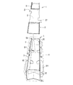
図1に示されるように、梱包材1は、基部2および緩衝部3を備える。本実施形態において、一対の緩衝部3が、基部2の長手方向の両端部に形成されている。
As shown in FIG. 1, the
基部2は、一の平面に沿って形成された平坦な部分である。緩衝部3は、基部2における一方の面の側に起立して形成されている。以下の説明において、基部2における緩衝部3が形成されている側の面を第1主面2aと称し、基部2における第1主面2aに対し反対側の面を第2主面2bと称する。
The
緩衝部3各々は、基部2の第1主面2aに沿う空間の三方を囲む部分である。緩衝部3各々は、第1縦板部31、第2縦板部32、第3縦板部33、第4縦板部34および鉤状部35を備える。
Each of the
第1縦板部31は、基部2に対して第1屈曲部41を介して連なり、基部2から第1主面2a側へ起立した部分である。即ち、第1屈曲部41は、基部2と第1縦板部31との境界線を成す部分である。
The first
第1縦板部31には、第1切れ込み313が形成されている。第1切れ込み313は、第1縦板部31におけるその起立方向に沿う一方の第1側縁311から基部2に沿って形成されている。
A
なお、第1縦板部31における、第1縦板部31の起立方向に沿う2箇所の側縁のうち、一方が第1側縁311であり、他方が第2側縁312である。第2側縁312は、第1縦板部31における第1側縁311の反対側の側縁である。
In the first
第2縦板部32は、基部2に対して第2屈曲部42を介して連なり、基部2から第1主面2a側へ起立した部分である。即ち、第2屈曲部42は、基部2と第2縦板部32との境界線を成す部分である。第2縦板部32は、第1縦板部31に対向して形成されている。
The second
第3縦板部33は、第2縦板部32に対し、第2縦板部32の起立方向に沿って形成された第3屈曲部43を介して連なる部分である。即ち、第3屈曲部43は、第2縦板部32と第3縦板部33との境界線を成す部分である。
The third
第3縦板部33は、第3屈曲部43から第4屈曲部44までに亘って形成されている。第4屈曲部44は、第1縦板部31の第2側縁312に沿って屈曲した部分である。
The third
第4縦板部34は、第3縦板部33に対して第4屈曲部44を介して連なる部分である。即ち、第4屈曲部44は、第3縦板部33と第4縦板部34との境界線を成す部分である。第4縦板部34は、第1縦板部における前記第2縦板部に対向する面の反対側の面に重なって形成されている。
The fourth
鉤状部35は、第4縦板部34に対し、第1切れ込み313に沿って形成された第5屈曲部45を介して連なる部分である。即ち、第5屈曲部45は、第4縦板部34と鉤状部35との境界線を成す部分である。鉤状部35は、第5屈曲部45から第1切れ込み313内を経て基部2の第1主面2aに重なる範囲に亘って形成されている。
The hook-shaped
鉤状部35には、第1縦板部31における第1切れ込み313の底部3130が挿入された第2切れ込み351が形成されている。即ち、鉤状部35は、第5屈曲部45から第2縦板部32側へ張り出し、さらに、第1屈曲部41に沿って第3縦板部33側へ延びた鉤状に形成されている。
A
従って、鉤状部35は、第1縦板部31における第1切れ込み313の底部3130に引っ掛かる。鉤状部35が第1切れ込み313の底部3130に引っ掛かった状態は、第2切れ込み351の底部3510と第1切れ込み313の底部3130とが対向し、第2切れ込み351と第1切れ込み313とが噛み合った状態である。
Accordingly, the hook-shaped
鉤状部35が第1切れ込み313の底部3130に引っ掛かることにより、第4縦板部34が第1縦板部31に重なった状態が維持され、さらに、第1縦板部31および第4縦板部34が起立する状態が維持される。
The hook-
ここで、第1縦板部31、第2縦板部32、第3縦板部33および第4縦板部34の基部2からの高さを、それぞれ第1高さH1、第2高さH2、第3高さH3および第4高さH4と称する。
Here, the height from the
本実施形態において、第1高さH1と第2高さH2とが等しい。また、第3高さH3は、第1高さH1および第2高さH2よりも低い。また、第4高さH4と第1高さH1とが等しい。 In the present embodiment, the first height H1 and the second height H2 are equal. The third height H3 is lower than the first height H1 and the second height H2. Further, the fourth height H4 is equal to the first height H1.
[梱包材1の利用方法]
図5において、被梱包品9および梱包箱6が、仮想線(2点鎖線)で示されている。例えば、被梱包品9は、電子写真方式の画像形成装置の部品であるドラムユニット、現像ユニットまたは定着ユニットなどである。
[How to use packing material 1]
In FIG. 5, the to-
被梱包品9は、段ボールで形成された内梱包容器5に収容される。収容部51は、その内側に被梱包品9の収容空間50を形成している。
The
図5,6に示されるように、内梱包容器5は、底板および四方の側板を有する収容部51と、収容部51の外側に形成された複数の緩衝部52,53,54とを備える。
As shown in FIGS. 5 and 6, the
複数の緩衝部52,53,54は、端面緩衝部52と、側面緩衝部53と、底面緩衝部54とを含む。端面緩衝部52は、内梱包容器5の長手方向の両端面の外側に形成されている。
The plurality of
側面緩衝部53は、内梱包容器5の両側面の外側に形成されている。なお、内梱包容器5の両側面は、内梱包容器5の短手方向の両端面である。底面緩衝部54は、内梱包容器5の底面に形成されている。
The
図5に示されるように、被梱包品9は、内梱包容器5に収容される。さらに、その内梱包容器5が、被梱包品9を内包する状態で、直方体状の梱包箱6に収容される。
As shown in FIG. 5, the packaged
また、梱包材1は、内梱包容器5に収容された被梱包品9の上に置かれる。これにより、梱包材1は、被梱包品9とともに梱包箱6内に収容され、被梱包品9の上面と梱包箱6の天板の下面との間隔を維持するスペーサー部材として機能する。梱包材1は、内梱包容器5などの他の梱包部材と連結されない独立した部材である。
Further, the packing
図1,5に示されるように、梱包材1の基部2には、基部2の長手方向に交差する方向へ張り出した張出部21が形成されている。張出部21は、内梱包容器5の収容部51に形成された欠け部511に挿入される。これにより、梱包材1の位置ズレが防がれる。
As shown in FIGS. 1 and 5, the
ところで、他の部材から独立した従来の梱包材は、上下および左右に板状部を有する角筒状に形成される場合が多い。図7,8に示される参考例に係る梱包材8は、従来の梱包材の典型例である。 By the way, the conventional packing material independent of other members is often formed in a rectangular tube shape having plate-like portions on the top and bottom and the left and right. The packaging material 8 according to the reference example shown in FIGS. 7 and 8 is a typical example of a conventional packaging material.
梱包材8は、予め罫線が形成された平坦な母材80を前記罫線に沿って折り曲げる作業によって作製される(図7参照)。図7に示される展開図は、平坦な母材80の平面図でもある。 The packing material 8 is produced by an operation of bending a flat base material 80 on which ruled lines are formed in advance along the ruled lines (see FIG. 7). The developed view shown in FIG. 7 is also a plan view of the flat base material 80.
図7において、2点鎖線が前記罫線を表す。図7に示される全ての前記罫線は、谷折りの折り目となる部分である。また、図7において、実線は母材80の外形および母材80に形成されたスリットを表す。また、ハッチングが記された部分は、母材80に形成された開口である。図7と図8とにおいて、相互に対応する部分には、同じ参照符号が付されている。 In FIG. 7, a two-dot chain line represents the ruled line. All the ruled lines shown in FIG. 7 are portions that become folds of valley folds. In FIG. 7, the solid line represents the outer shape of the base material 80 and the slits formed in the base material 80. Further, hatched portions are openings formed in the base material 80. In FIG. 7 and FIG. 8, the parts corresponding to each other are denoted by the same reference numerals.
図8に示されるように、従来の梱包材8は、基部81および緩衝部82を備える。緩衝部82は、上下および左右に板状部を有する角筒状に形成されている。
As shown in FIG. 8, the conventional packing material 8 includes a
即ち、緩衝部82は、底板部86、天板部84、第1側板部83および第2側板部85を有する。また、基部2から切り起こされた係合片87が、底板部86から第2側板部85に亘って形成された開口88に挿入されている。
That is, the
係合片87の根本部以外の部分は、開口88の幅よりも広い幅で形成されている。係合片87が。開口88の縁部に引っ掛かることにより、緩衝部82が角筒状に維持される。図7,8に示される例では、一対の緩衝部82が、基部81の長手方向の両端部に形成されている。
The portion other than the base portion of the
上記の場合、梱包材8は、外力F0を受ける方向に沿って形成された一対の側板部83,85が潰れることにより、緩衝機能を発揮する。
In the above case, the packing material 8 exhibits a buffering function when the pair of
しかしながら、梱包材8の角筒状の緩衝部82は、外力F0を受けたときに、断面形状が長方形から平行四辺形に変形しやすい(図8の2点鎖線を参照)。即ち、外力F0を受ける方向に沿って形成された一対の側板部83,85が、潰れる前に、外力F0の方向に交差する方向へ倒れやすい。そうすると、梱包材8が、本来の緩衝性能を発揮しないおそれがある。
However, the square
また、梱包材8が作製および解体される際に、母材80が、予め形成された前記罫線とは異なる部分で折り曲げられることが多い。図7,8に示される例では、係合片87が、前記罫線とは異なる部分で一時的に折り曲げられてしまう。そうすると、母材80が劣化し、梱包材8の再利用が難しくなる。
In addition, when the packaging material 8 is manufactured and disassembled, the base material 80 is often bent at a portion different from the ruled line formed in advance. In the example shown in FIGS. 7 and 8, the
従って、梱包材8の再利用性を高めるためには、梱包材8が母材80から作製される過程、および、梱包材8が元の母材80へ解体される過程において、材料が劣化しにくいことが望ましい。 Therefore, in order to improve the reusability of the packaging material 8, the material deteriorates in the process of producing the packaging material 8 from the base material 80 and the process of disassembling the packaging material 8 into the original base material 80. It is desirable that it is difficult.
前述したように、梱包材1は、外力F0を受ける方向に沿って形成された板状部である第1縦板部31および第2縦板部32を備える。そして、梱包材1が採用されれば、第1縦板部31および第2縦板部32が倒れることによる緩衝性能の悪化を回避できる。さらに、梱包材1は、作製および解体の過程における材料の劣化が生じにくい。以下、梱包材1の作用および効果について説明する。
As described above, the
[梱包材1の作用および効果]
梱包材1において、主として第1縦板部31および第2縦板部32が、それらの起立方向に沿って加わる外力F0を受けたときに潰れることにより、緩衝性を発揮する。なお、第3縦板部33および第4縦板部34も、補助的に緩衝性を発揮する。
[Action and effect of packing material 1]
In the
図2に示される破線は、段ボールの目方向100を表す。目方向100は、段ボールのトラス構造における中空の長手方向である。
The broken line shown in FIG. 2 represents the
例えば図2に示されるように、第1縦板部31および第2縦板部32の目方向100が、それらの起立方向に直交する横方向であることが考えられる。これにより、外力F0に対する緩衝性がより高まる。
For example, as shown in FIG. 2, it is conceivable that the
なお、第1縦板部31および第2縦板部32の目方向100が前記横方向であれば、第3縦板部33および第4縦板部34の目方向100も、前記横方向となる。
If the
一方、外力F0に対する緩衝部3の剛性を高めたい場合、第1縦板部31および第2縦板部32の目方向100が、それらの起立方向に沿う縦方向であることが考えられる。これにより、外力F0に対する剛性が高まる。
On the other hand, when it is desired to increase the rigidity of the
梱包材1において、第3縦板部33が、第2縦板部32および第4縦板部34を連結している。そのため、第2縦板部32および第4縦板部34が、外力F0に交差する横方向の力を受けた場合、第3縦板部33が、その横方向の力に抗して、第2縦板部32および第4縦板部34を起立した状態に維持する。また、第3縦板部33と第2縦板部32および第4縦板部34との間の第3屈曲部43および第4屈曲部44において折り曲げることで形成される角部によっても、第2縦板部32、第3縦板部33、第3縦板部34は、外力F0の方向における剛性が高まる。
In the
さらに、鉤状部35が、第1縦板部31および第4縦板部34を重なった状態に維持する。そのため、第4縦板部34が第3縦板部33によって起立する状態に維持されれば、第1縦板部31も起立する状態に維持される。
Further, the bowl-shaped
従って、梱包材1が採用されれば、第1縦板部31および第2縦板部32が倒れることによる緩衝性能の悪化を回避できる。
Therefore, if the
また、図1,3に示されるように、一対の緩衝部3の第3縦板部33は、基部2の長手方向の中央側に形成されている。さらに、基部2の長手方向の中央から一対の緩衝部3各々を見た場合における緩衝部3の各構成要素の左右の位置関係が同じである。ここで、緩衝部3の各構成要素とは、第1縦板部31、第2縦板部32、第3縦板部33、第4縦板部34および鉤状部35のことである。
As shown in FIGS. 1 and 3, the third
一対の緩衝部3の各構成要素が、上記のような位置関係で形成されている場合、母材10の形状が、図3に示されるように比較的正方形に近い形状になる。一方、図7に示されるような従来の梱包材8の母材80は、細長く形成される。
When the constituent elements of the pair of
母材10の形状が正方形に近い場合、梱包材1が作製および解体される際などにおいて、母材10を取り扱いやすい。
When the shape of the base material 10 is close to a square, it is easy to handle the base material 10 when the
また、母材10からの梱包材1の作製手順は、例えば以下の通りである。まず、母材10が前記罫線に沿って折り曲げられることにより、各屈曲部41〜45が形成される。
Moreover, the preparation procedure of the
次に、図4に示されるように、第1縦板部31が基部2の第1主面2a側へ斜めに倒れるように押さえられた状態で、鉤状部35が第1縦板部31の第1切れ込み313に引っ掛けられる。その後、第1縦板部31が、基部2から直立する方向、即ち、第4縦板部34に重なる方向へ引き起こされる。これにより、第1縦板部31が、第3縦板部33と鉤状部35における第1切れ込み313の底部3130との間に挟み込まれる。なお、梱包材1は、梱包材1の作製の手順と逆の手順で解体可能である。
Next, as shown in FIG. 4, the hook-shaped
梱包材1が母材10から上記のように作製される場合、母材10が前記罫線とは異なる部分で折り曲げられる工程は生じない。そのため、梱包材1の作製および解体が繰り返されても、材料が劣化しにくい。そのため、梱包材1は、高い再利用性を有している。
When the
また、図1,3,4に示されるように、第3縦板部33における基部2の第1主面2aに対向する縁に、欠け部331が形成されている。欠け部331は、第4屈曲部44側から基部2に沿って形成されている。
As shown in FIGS. 1, 3, and 4, a chipped
欠け部331の基部2に沿う方向の幅W1は、第1高さH1よりも大きい(図1参照)。この場合、図4に示される手順において、第1縦板部31における第2側縁312側の端部が、第3縦板部33の下方を潜りやすい。
The width W1 of the chipped
従って、鉤状部35を第1縦板部31の第1切れ込み313に引っ掛ける工程、および、鉤状部35を第1切れ込み313から外す工程を円滑に行うことができる。さらに、第1縦板部31が第3縦板部33に引っ掛かることによる母材10の不測の劣化が生じにくい。
Therefore, the step of hooking the hook-shaped
また、図1,3,4に示されるように、第1縦板部31の外縁に傾斜縁315が形成されている。傾斜縁315は、第1縦板部31の外縁における第2側縁312と頭頂の縁314との間に形成された傾斜した縁である。なお、頭頂の縁314は、第1屈曲部41に対して反対側の縁である。
As shown in FIGS. 1, 3, and 4, an
傾斜縁315が形成されている場合、図4に示される手順において、第1縦板部31における第2側縁312側の端部が、第3縦板部33の下方をより潜りやすくなる。従って、鉤状部35を第1縦板部31の第1切れ込み313に引っ掛ける工程、および、鉤状部35を第1切れ込み313から外す工程をより円滑に行うことができる。
When the
[応用例]
図1に示される梱包材1において、第4高さH4が、第1高さH1よりも低いことが考えられる。この場合、第1縦板部31および第2縦板部32の緩衝性のバランスが均一化されやすい。
[Application example]
In the
また、図1に示される梱包材1において、外力F0に対する緩衝部3の剛性を高めたい場合、第3高さH3が、第1高さH1および第2高さH2と同じ高さで形成されることも考えられる。
Further, in the
なお、本発明に係る梱包材は、各請求項に記載された発明の範囲において、以上に示された実施形態及び応用例を自由に組み合わせること、或いは実施形態及び応用例を適宜、変形する又は一部を省略することによって構成されることも可能である。 The packaging material according to the present invention can be freely combined with the above-described embodiment and application examples within the scope of the invention described in each claim, or can be modified as appropriate. It is also possible to configure by omitting a part.
1 :梱包材
2 :基部
2a :第1主面
2b :第2主面
3 :緩衝部
5 :内梱包容器
6 :梱包箱
9 :被梱包品
10 :母材
21 :張出部
31 :第1縦板部
32 :第2縦板部
33 :第3縦板部
34 :第4縦板部
35 :鉤状部
41 :第1屈曲部
42 :第2屈曲部
43 :第3屈曲部
44 :第4屈曲部
45 :第5屈曲部
50 :収容空間
51 :収容部
100 :目方向
311 :第1縦板部の第1側縁
312 :第1縦板部の第2側縁
313 :第1切れ込み
314 :第1縦板部の頭頂の縁
315 :傾斜縁
331 :欠け部
351 :第2切れ込み
3130 :第1切れ込みの底部
3510 :第2切れ込みの底部
F0 :外力
H1 :第1高さ(第1縦板部の高さ)
H2 :第2高さ(第2縦板部の高さ)
H3 :第3高さ(第3縦板部の高さ)
H4 :第4高さ(第4縦板部の高さ)
DESCRIPTION OF SYMBOLS 1: Packing material 2:
H2: Second height (the height of the second vertical plate)
H3: Third height (the height of the third vertical plate)
H4: Fourth height (the height of the fourth vertical plate)
Claims (4)
一の平面に沿って形成された基部と、
前記基部の一の主面に沿う空間の三方を囲む緩衝部と、を備え、
前記緩衝部は、
前記基部に対して第1屈曲部を介して連なり、前記基部から前記基部の前記主面側へ起立し、起立方向に沿う一方の第1側縁から前記基部に沿って第1切れ込みが形成された第1縦板部と、
前記基部に対して第2屈曲部を介して連なり、前記基部から前記基部の前記主面側へ起立し、前記第1縦板部に対向して形成された第2縦板部と、
前記第2縦板部に対し、前記第2縦板部の起立方向に沿って形成された第3屈曲部を介して連なり、前記第3屈曲部から前記第1縦板部における前記第1側縁の反対側の第2側縁に沿う第4屈曲部までに亘って形成された第3縦板部と、
前記第3縦板部に対して前記第4屈曲部を介して連なり、前記第1縦板部における前記第2縦板部に対向する面の反対側の面に重なって形成された第4縦板部と、
前記第4縦板部に対し、前記第1切れ込みに沿って形成された第5屈曲部を介して連なり、前記第5屈曲部から前記第1切れ込み内を経て前記基部の前記主面に重なる範囲に亘って形成され、前記第1縦板部における前記第1切れ込みの底の部分が挿入された第2切れ込みが形成された鉤状部と、を備える梱包材。 It is a packing material that is formed of a shock-absorbing plate and is housed in the packing box together with the packaged product,
A base formed along one plane;
A buffer part surrounding three sides of the space along one main surface of the base part, and
The buffer portion is
A first notch is formed along the base from the first side edge along one of the first side edges along the rising direction. The first notch is connected to the base via a first bent portion and rises from the base toward the main surface of the base. A first vertical plate portion;
A second vertical plate portion that is connected to the base portion via a second bent portion, rises from the base portion to the main surface side of the base portion, and is formed to face the first vertical plate portion;
It is connected to the second vertical plate portion via a third bent portion formed along the rising direction of the second vertical plate portion, and the first side of the first vertical plate portion from the third bent portion. A third vertical plate portion formed over the fourth bent portion along the second side edge on the opposite side of the edge;
A fourth vertical portion that is connected to the third vertical plate portion via the fourth bent portion and overlaps with a surface of the first vertical plate portion opposite to the surface facing the second vertical plate portion. A plate part;
A range that is continuous with the fourth vertical plate portion via a fifth bent portion formed along the first cut and overlaps with the main surface of the base portion from the fifth bent portion through the first cut. And a bowl-shaped part formed with a second notch formed by inserting a bottom part of the first notch in the first vertical plate part.
前記欠け部の前記基部に沿う方向の幅は、前記第1縦板部の前記基部からの起立方向の高さよりも大きい、請求項1に記載の梱包材。 A chipped portion formed along the base portion from the fourth bent portion side is formed on an edge of the third vertical plate portion facing the main surface of the base portion,
The packaging material according to claim 1, wherein a width of the chipped portion in a direction along the base portion is larger than a height of the first vertical plate portion in a standing direction from the base portion.
一対の前記緩衝部の前記第3縦板部は、前記基部の長手方向の中央側に形成されており、
前記基部の長手方向の中央から一対の前記緩衝部各々を見た場合における前記緩衝部の各構成要素の左右の位置関係が同じである、請求項1から請求項3のいずれか1項に記載の梱包材。 A pair of the buffer portions are formed at both ends in the longitudinal direction of the base portion,
The third vertical plate part of the pair of buffer parts is formed on the center side in the longitudinal direction of the base part,
The left-right positional relationship of each component of the said buffer part when each of a pair of said buffer part is seen from the center of the longitudinal direction of the said base part is the same as any one of Claims 1-3. Packing material.
Priority Applications (2)
| Application Number | Priority Date | Filing Date | Title |
|---|---|---|---|
| JP2015226965A JP6358239B2 (en) | 2015-11-19 | 2015-11-19 | Packing material |
| US15/353,560 US10046898B2 (en) | 2015-11-19 | 2016-11-16 | Packaging material |
Applications Claiming Priority (1)
| Application Number | Priority Date | Filing Date | Title |
|---|---|---|---|
| JP2015226965A JP6358239B2 (en) | 2015-11-19 | 2015-11-19 | Packing material |
Publications (3)
| Publication Number | Publication Date |
|---|---|
| JP2017095123A JP2017095123A (en) | 2017-06-01 |
| JP2017095123A5 JP2017095123A5 (en) | 2018-06-21 |
| JP6358239B2 true JP6358239B2 (en) | 2018-07-18 |
Family
ID=58719971
Family Applications (1)
| Application Number | Title | Priority Date | Filing Date |
|---|---|---|---|
| JP2015226965A Active JP6358239B2 (en) | 2015-11-19 | 2015-11-19 | Packing material |
Country Status (2)
| Country | Link |
|---|---|
| US (1) | US10046898B2 (en) |
| JP (1) | JP6358239B2 (en) |
Families Citing this family (1)
| Publication number | Priority date | Publication date | Assignee | Title |
|---|---|---|---|---|
| JP7352144B2 (en) * | 2019-07-18 | 2023-09-28 | コニカミノルタ株式会社 | Cushioning material, packaging and packaging method |
Family Cites Families (3)
| Publication number | Priority date | Publication date | Assignee | Title |
|---|---|---|---|---|
| JP5707838B2 (en) * | 2010-10-08 | 2015-04-30 | 富士ゼロックス株式会社 | Packing box |
| JP5707360B2 (en) * | 2012-04-25 | 2015-04-30 | 京セラドキュメントソリューションズ株式会社 | Buffer unit and device maintenance method |
| JP2013228605A (en) | 2012-04-26 | 2013-11-07 | Yutaka Kasashima | Lens fixing structure in wooden or bamboo spectacle frame |
-
2015
- 2015-11-19 JP JP2015226965A patent/JP6358239B2/en active Active
-
2016
- 2016-11-16 US US15/353,560 patent/US10046898B2/en active Active
Also Published As
| Publication number | Publication date |
|---|---|
| JP2017095123A (en) | 2017-06-01 |
| US10046898B2 (en) | 2018-08-14 |
| US20170144819A1 (en) | 2017-05-25 |
Similar Documents
| Publication | Publication Date | Title |
|---|---|---|
| JP6358239B2 (en) | Packing material | |
| JP5563375B2 (en) | Packaging box with lifting support function | |
| JP5124300B2 (en) | Buffer packaging material | |
| JP4936933B2 (en) | Packing tray | |
| JP3177073U (en) | Partition body and spherical storage box including the same | |
| JP5209450B2 (en) | Packaging frame | |
| JP6669007B2 (en) | Packing materials | |
| JP2019064719A (en) | Packaging box | |
| JP3174085U (en) | Partition | |
| JP6477583B2 (en) | Packing material | |
| US9126710B2 (en) | Carton | |
| JP6508106B2 (en) | Packing material | |
| JP2015067294A (en) | Buffer structure for packed article | |
| JP3194255U (en) | Cardboard cases | |
| JP3219316U (en) | Cardboard blocks | |
| JP6911452B2 (en) | Support members and packing equipment | |
| JP2007254016A (en) | Packaging material | |
| JP2010036926A (en) | Corrugated board cushioning material | |
| JP6468238B2 (en) | Packing material | |
| JP3137157U (en) | Assembly packaging material | |
| JP3208239U (en) | Packaging box | |
| TWI435831B (en) | Packaging assembly | |
| JP2012166822A (en) | Cushioning member | |
| JP6207456B2 (en) | Packing structure | |
| JP5124166B2 (en) | Buffer packaging material |
Legal Events
| Date | Code | Title | Description |
|---|---|---|---|
| A621 | Written request for application examination |
Free format text: JAPANESE INTERMEDIATE CODE: A621 Effective date: 20170824 |
|
| A977 | Report on retrieval |
Free format text: JAPANESE INTERMEDIATE CODE: A971007 Effective date: 20180507 |
|
| A521 | Written amendment |
Free format text: JAPANESE INTERMEDIATE CODE: A523 Effective date: 20180509 |
|
| TRDD | Decision of grant or rejection written | ||
| A01 | Written decision to grant a patent or to grant a registration (utility model) |
Free format text: JAPANESE INTERMEDIATE CODE: A01 Effective date: 20180522 |
|
| A61 | First payment of annual fees (during grant procedure) |
Free format text: JAPANESE INTERMEDIATE CODE: A61 Effective date: 20180604 |
|
| R150 | Certificate of patent or registration of utility model |
Ref document number: 6358239 Country of ref document: JP Free format text: JAPANESE INTERMEDIATE CODE: R150 |