JP6350737B2 - Evaporation component system - Google Patents
Evaporation component system Download PDFInfo
- Publication number
- JP6350737B2 JP6350737B2 JP2017501345A JP2017501345A JP6350737B2 JP 6350737 B2 JP6350737 B2 JP 6350737B2 JP 2017501345 A JP2017501345 A JP 2017501345A JP 2017501345 A JP2017501345 A JP 2017501345A JP 6350737 B2 JP6350737 B2 JP 6350737B2
- Authority
- JP
- Japan
- Prior art keywords
- ejector
- port
- supercharger
- fuel vapor
- passage
- Prior art date
- Legal status (The legal status is an assumption and is not a legal conclusion. Google has not performed a legal analysis and makes no representation as to the accuracy of the status listed.)
- Expired - Fee Related
Links
Images

Classifications
-
- F—MECHANICAL ENGINEERING; LIGHTING; HEATING; WEAPONS; BLASTING
- F02—COMBUSTION ENGINES; HOT-GAS OR COMBUSTION-PRODUCT ENGINE PLANTS
- F02M—SUPPLYING COMBUSTION ENGINES IN GENERAL WITH COMBUSTIBLE MIXTURES OR CONSTITUENTS THEREOF
- F02M25/00—Engine-pertinent apparatus for adding non-fuel substances or small quantities of secondary fuel to combustion-air, main fuel or fuel-air mixture
- F02M25/08—Engine-pertinent apparatus for adding non-fuel substances or small quantities of secondary fuel to combustion-air, main fuel or fuel-air mixture adding fuel vapours drawn from engine fuel reservoir
- F02M25/0809—Judging failure of purge control system
-
- F—MECHANICAL ENGINEERING; LIGHTING; HEATING; WEAPONS; BLASTING
- F02—COMBUSTION ENGINES; HOT-GAS OR COMBUSTION-PRODUCT ENGINE PLANTS
- F02M—SUPPLYING COMBUSTION ENGINES IN GENERAL WITH COMBUSTIBLE MIXTURES OR CONSTITUENTS THEREOF
- F02M25/00—Engine-pertinent apparatus for adding non-fuel substances or small quantities of secondary fuel to combustion-air, main fuel or fuel-air mixture
- F02M25/08—Engine-pertinent apparatus for adding non-fuel substances or small quantities of secondary fuel to combustion-air, main fuel or fuel-air mixture adding fuel vapours drawn from engine fuel reservoir
- F02M25/0836—Arrangement of valves controlling the admission of fuel vapour to an engine, e.g. valve being disposed between fuel tank or absorption canister and intake manifold
-
- F—MECHANICAL ENGINEERING; LIGHTING; HEATING; WEAPONS; BLASTING
- F02—COMBUSTION ENGINES; HOT-GAS OR COMBUSTION-PRODUCT ENGINE PLANTS
- F02M—SUPPLYING COMBUSTION ENGINES IN GENERAL WITH COMBUSTIBLE MIXTURES OR CONSTITUENTS THEREOF
- F02M25/00—Engine-pertinent apparatus for adding non-fuel substances or small quantities of secondary fuel to combustion-air, main fuel or fuel-air mixture
- F02M25/08—Engine-pertinent apparatus for adding non-fuel substances or small quantities of secondary fuel to combustion-air, main fuel or fuel-air mixture adding fuel vapours drawn from engine fuel reservoir
- F02M25/089—Layout of the fuel vapour installation
-
- F—MECHANICAL ENGINEERING; LIGHTING; HEATING; WEAPONS; BLASTING
- F02—COMBUSTION ENGINES; HOT-GAS OR COMBUSTION-PRODUCT ENGINE PLANTS
- F02M—SUPPLYING COMBUSTION ENGINES IN GENERAL WITH COMBUSTIBLE MIXTURES OR CONSTITUENTS THEREOF
- F02M26/00—Engine-pertinent apparatus for adding exhaust gases to combustion-air, main fuel or fuel-air mixture, e.g. by exhaust gas recirculation [EGR] systems
- F02M26/02—EGR systems specially adapted for supercharged engines
- F02M26/03—EGR systems specially adapted for supercharged engines with a single mechanically or electrically driven intake charge compressor
-
- F—MECHANICAL ENGINEERING; LIGHTING; HEATING; WEAPONS; BLASTING
- F02—COMBUSTION ENGINES; HOT-GAS OR COMBUSTION-PRODUCT ENGINE PLANTS
- F02M—SUPPLYING COMBUSTION ENGINES IN GENERAL WITH COMBUSTIBLE MIXTURES OR CONSTITUENTS THEREOF
- F02M26/00—Engine-pertinent apparatus for adding exhaust gases to combustion-air, main fuel or fuel-air mixture, e.g. by exhaust gas recirculation [EGR] systems
- F02M26/13—Arrangement or layout of EGR passages, e.g. in relation to specific engine parts or for incorporation of accessories
- F02M26/17—Arrangement or layout of EGR passages, e.g. in relation to specific engine parts or for incorporation of accessories in relation to the intake system
-
- G—PHYSICS
- G01—MEASURING; TESTING
- G01M—TESTING STATIC OR DYNAMIC BALANCE OF MACHINES OR STRUCTURES; TESTING OF STRUCTURES OR APPARATUS, NOT OTHERWISE PROVIDED FOR
- G01M15/00—Testing of engines
- G01M15/04—Testing internal-combustion engines
- G01M15/09—Testing internal-combustion engines by monitoring pressure in fluid ducts, e.g. in lubrication or cooling parts
Landscapes
- Engineering & Computer Science (AREA)
- Chemical & Material Sciences (AREA)
- Combustion & Propulsion (AREA)
- Mechanical Engineering (AREA)
- General Engineering & Computer Science (AREA)
- Supplying Secondary Fuel Or The Like To Fuel, Air Or Fuel-Air Mixtures (AREA)
Description
相互参照:本出願は、2014年9月10日に出願された米国の仮出願62/048,567、および2015年4月3日に出願された米国特許出願14/678,241に基づくものであり、それらの内容は、参照によってここに組込まれる。
Cross-reference: This application is based on US
現在の開示は内燃機関用の蒸発成分システムに関係がある。 The current disclosure relates to an evaporative component system for an internal combustion engine.
従来、内燃機関は、蒸発成分システムを装備している。蒸発成分システムは、燃料タンクの中で生成された燃料蒸気を吸収するために活性炭フィルタを収容する燃料蒸気捕捉容器を含んでいる。蒸発成分システムは、吸収された燃料蒸気を機関のインテークマニホルドへ送るように構成されており、それにより、吸収された燃料蒸気を機関の燃焼室で燃焼する。このように、蒸発成分システムは、大気への燃料蒸気汚染として、燃料タンクの中で生成された燃料蒸気の逃げを制限する。 Conventionally, internal combustion engines are equipped with an evaporative component system. The evaporative component system includes a fuel vapor capture vessel that contains an activated carbon filter to absorb the fuel vapor generated in the fuel tank. The evaporative component system is configured to send absorbed fuel vapor to the engine intake manifold, thereby combusting the absorbed fuel vapor in the engine combustion chamber. Thus, the evaporative component system limits the escape of fuel vapor generated in the fuel tank as fuel vapor contamination to the atmosphere.
蒸発成分システムは、吸収された燃料蒸気を、燃料蒸気捕捉容器から、機関の燃焼室の中へ取り出すために、エジェクタのような運搬システムを含んでいてもよい。運搬システムが、そこを通る燃料蒸気の漏洩を生じるような通路の破損のような不具合を生じることが懸念される。 The evaporative component system may include a delivery system, such as an ejector, for removing absorbed fuel vapor from the fuel vapor capture vessel into the combustion chamber of the engine. There is a concern that the transport system may suffer from problems such as breakage of the passages that cause leakage of fuel vapor therethrough.
この開示は上記の懸念に取り組むものである。 This disclosure addresses the above concerns.
開示の蒸発成分システムは、内燃機関(11)のための蒸発成分システムであって、内燃機関は、吸入空気を加圧するための過給機(52)を備えるインテークパイプ(21)を有しており、過給機(52)の上流へ燃料蒸気を引き込むための負圧を生成するために、過給機(52)の下流から、過給機(52)の上流に吸入空気の流れを引くように構成されたエジェクタ(42)と、過給機(52)の下流から分岐し、過給機(52)の上流にエジェクタ(42)を通して戻されるエジェクタ通路(56、42a、58)と、エジェクタ通路(56、42a、58)に連通しており、エジェクタ通路(56、42a、58)の圧力を検出するように構成された圧力センサ(60、260、360)と、燃料蒸気を吸収するように、かつエジェクタ(42)に燃料蒸気を供給するように構成されている燃料蒸気捕捉容器(18)とを備え、エジェクタ(42)は、第1ポート(46)、第2ポート(48)および第3ポート(50)を有し、第1ポート(46)は燃料蒸気捕捉容器(18)と流体的に連通しており、第2ポート(48)は過給機(52)の下流と流体的に連通しており、第3ポート(50)は過給機(52)の上流に流体的に連通しており、エジェクタ(42)は第2ポート(48)と第3ポート(50)との間で、エジェクタ通路(56、42a、58)の一部であるベンチュリ通路(42a)を形成しており、圧力センサ(60)は、第3ポート(50)と過給機(52)の上流との間の通路に流体的に連通しており、さらに、圧力センサ(60、260、360)で検知された圧力を表わす情報を取得するために圧力センサ(60、260、360)と接続された制御装置(80)を備え、制御装置(80)は、検知された圧力中の内燃機関のシリンダから伝搬してきた脈動についての情報を取得し、かつ脈動についての情報によってエジェクタ通路(56、42a、58)における漏洩を決定するように構成されている。 The disclosed evaporative component system is an evaporative component system for an internal combustion engine (11), the internal combustion engine having an intake pipe (21) with a supercharger (52) for pressurizing intake air. In order to generate a negative pressure for drawing fuel vapor upstream of the supercharger (52), a flow of intake air is drawn from the downstream of the supercharger (52) to the upstream of the supercharger (52). An ejector (42) configured as described above, an ejector passage (56, 42a, 58) branched from the downstream of the supercharger (52) and returned to the upstream of the supercharger (52) through the ejector (42), Pressure sensors (60, 260, 360) communicating with the ejector passages (56, 42a, 58) and configured to detect the pressure in the ejector passages (56, 42a, 58) and absorbing fuel vapor And A fuel vapor capture vessel (18) configured to supply fuel vapor to the kuta (42), the ejector (42) comprising a first port (46), a second port (48) and a third port (50), the first port (46) is in fluid communication with the fuel vapor capture vessel (18), and the second port (48) is in fluid communication with the downstream of the supercharger (52). The third port (50) is in fluid communication with the upstream of the supercharger (52), and the ejector (42) is located between the second port (48) and the third port (50). Forming a venturi passage (42a) that is part of the ejector passage (56, 42a, 58), and the pressure sensor (60) is connected to the third port (50) and the upstream of the supercharger (52). and in fluid communication with the passage between, further, the pressure sensor (60,260,3 A control device (80) connected to the pressure sensors (60, 260, 360) to obtain information representing the pressure sensed at 0), the control device (80) being an internal combustion engine in the sensed pressure. Information on the pulsation propagating from the cylinder of the engine is acquired, and leakage in the ejector passage (56, 42a, 58) is determined based on the information on the pulsation .
開示の蒸発成分システムは、内燃機関(11)のための蒸発成分システムであって、内燃機関は、吸入空気を加圧するための過給機(52)を備えるインテークパイプ(21)を有しており、過給機(52)の上流へ燃料蒸気を引き込むための負圧を生成するために、過給機(52)の下流から、過給機(52)の上流に吸入空気の流れを引くように構成されたエジェクタ(42)と、過給機(52)の下流から分岐し、過給機(52)の上流にエジェクタ(42)を通して戻されるエジェクタ通路(56、42a、58)と、エジェクタ通路(56、42a、58)に連通しており、エジェクタ通路(56、42a、58)の圧力を検出するように構成された圧力センサ(60、260、360)と、燃料蒸気を吸収するように、かつエジェクタ(42)に燃料蒸気を供給するように構成されている燃料蒸気捕捉容器(18)とを備え、エジェクタ(42)は、第1ポート(46)、第2ポート(48)および第3ポート(50)を有し、第1ポート(46)は燃料蒸気捕捉容器(18)と流体的に連通しており、第2ポート(48)は過給機(52)の下流と流体的に連通しており、第3ポート(50)は過給機(52)の上流に流体的に連通しており、エジェクタ(42)は第2ポート(48)と第3ポート(50)との間で、エジェクタ通路(56、42a、58)の一部であるベンチュリ通路(42a)を形成しており、圧力センサ(260)は、エジェクタ(42)に統合されており、ベンチュリ通路(42a)に流体的に連通しており、さらに、圧力センサ(60、260、360)で検知された圧力を表わす情報を取得するために圧力センサ(60、260、360)と接続された制御装置(80)を備え、制御装置(80)は、検知された圧力中の内燃機関のシリンダから伝搬してきた脈動についての情報を取得し、かつ脈動についての情報によってエジェクタ通路(56、42a、58)における漏洩を決定するように構成されている。
開示の蒸発成分システムは、内燃機関(11)のための蒸発成分システムであって、内燃機関は、吸入空気を加圧するための過給機(52)を備えるインテークパイプ(21)を有しており、過給機(52)の上流へ燃料蒸気を引き込むための負圧を生成するために、過給機(52)の下流から、過給機(52)の上流に吸入空気の流れを引くように構成されたエジェクタ(42)と、過給機(52)の下流から分岐し、過給機(52)の上流にエジェクタ(42)を通して戻されるエジェクタ通路(56、42a、58)と、エジェクタ通路(56、42a、58)に連通しており、エジェクタ通路(56、42a、58)の圧力を検出するように構成された圧力センサ(60、260、360)と、燃料蒸気を吸収するように、かつエジェクタ(42)に燃料蒸気を供給するように構成されている燃料蒸気捕捉容器(18)とを備え、エジェクタ(42)は、第1ポート(46)、第2ポート(48)および第3ポート(50)を有し、第1ポート(46)は燃料蒸気捕捉容器(18)と流体的に連通しており、第2ポート(48)は過給機(52)の下流と流体的に連通しており、第3ポート(50)は過給機(52)の上流に流体的に連通しており、エジェクタ(42)は第2ポート(48)と第3ポート(50)との間で、エジェクタ通路(56、42a、58)の一部であるベンチュリ通路(42a)を形成しており、圧力センサ(360)は、第2ポート(48)と過給機(52)の下流との間の通路に流体的に連通しており、さらに、圧力センサ(60、260、360)で検知された圧力を表わす情報を取得するために圧力センサ(60、260、360)と接続された制御装置(80)を備え、制御装置(80)は、検知された圧力中の内燃機関のシリンダから伝搬してきた脈動についての情報を取得し、かつ脈動についての情報によってエジェクタ通路(56、42a、58)における漏洩を決定するように構成されている。
The disclosed evaporative component system is an evaporative component system for an internal combustion engine (11), the internal combustion engine having an intake pipe (21) with a supercharger (52) for pressurizing intake air. In order to generate a negative pressure for drawing fuel vapor upstream of the supercharger (52), a flow of intake air is drawn from the downstream of the supercharger (52) to the upstream of the supercharger (52). An ejector (42) configured as described above, an ejector passage (56, 42a, 58) branched from the downstream of the supercharger (52) and returned to the upstream of the supercharger (52) through the ejector (42), Pressure sensors (60, 260, 360) communicating with the ejector passages (56, 42a, 58) and configured to detect the pressure in the ejector passages (56, 42a, 58) and absorbing fuel vapor And A fuel vapor capture vessel (18) configured to supply fuel vapor to the kuta (42), the ejector (42) comprising a first port (46), a second port (48) and a third port (50), the first port (46) is in fluid communication with the fuel vapor capture vessel (18), and the second port (48) is in fluid communication with the downstream of the supercharger (52). The third port (50) is in fluid communication with the upstream of the supercharger (52), and the ejector (42) is located between the second port (48) and the third port (50). , Forming a venturi passage (42a) that is part of the ejector passage (56, 42a, 58), and the pressure sensor (260) is integrated into the ejector (42), and fluid is passed through the venturi passage (42a). manner communicates further pressure sensor (60, 60, 360) comprising a control device (80) connected to a pressure sensor (60, 260, 360) to obtain information representative of the pressure sensed by the control device (80), The information on the pulsation propagating from the cylinder of the internal combustion engine is acquired, and the leakage in the ejector passage (56, 42a, 58) is determined based on the information on the pulsation .
The disclosed evaporative component system is an evaporative component system for an internal combustion engine (11), the internal combustion engine having an intake pipe (21) with a supercharger (52) for pressurizing intake air. In order to generate a negative pressure for drawing fuel vapor upstream of the supercharger (52), a flow of intake air is drawn from the downstream of the supercharger (52) to the upstream of the supercharger (52). An ejector (42) configured as described above, an ejector passage (56, 42a, 58) branched from the downstream of the supercharger (52) and returned to the upstream of the supercharger (52) through the ejector (42), Pressure sensors (60, 260, 360) communicating with the ejector passages (56, 42a, 58) and configured to detect the pressure in the ejector passages (56, 42a, 58) and absorbing fuel vapor And A fuel vapor capture vessel (18) configured to supply fuel vapor to the kuta (42), the ejector (42) comprising a first port (46), a second port (48) and a third port (50), the first port (46) is in fluid communication with the fuel vapor capture vessel (18), and the second port (48) is in fluid communication with the downstream of the supercharger (52). The third port (50) is in fluid communication with the upstream of the supercharger (52), and the ejector (42) is located between the second port (48) and the third port (50). Forming a venturi passage (42a) that is part of the ejector passage (56, 42a, 58), and the pressure sensor (360) is connected to the second port (48) and the downstream of the supercharger (52). the passage between and in fluid communication, and further, a pressure sensor (60, 260, 60) a control device (80) connected to the pressure sensor (60, 260, 360) for obtaining information representative of the pressure detected in 60), wherein the control device (80) is an internal combustion engine in the detected pressure. Information on the pulsation propagating from the cylinder of the engine is acquired, and leakage in the ejector passage (56, 42a, 58) is determined based on the information on the pulsation .
添付の複数の図面を参照してなされた後述の説明から、この開示における上記目的および他の目的、特徴、そして利点は、より明白になる。 These and other objects, features and advantages of this disclosure will become more apparent from the following description made with reference to the accompanying drawings.
(第1実施形態)
以下において、この開示による第1実施形態が図面を参照して説明される。
(First embodiment)
In the following, a first embodiment according to this disclosure will be described with reference to the drawings.
複数の図において、図中の「ベーパ」は燃料蒸気を示し、図中の「キャニスタ」は燃料蒸気捕捉容器18を示し、図中の「モニタ」は蒸発成分システムモニタ(ESM)32を示す。
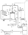
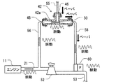
図1では、蒸発成分放出制御装置(蒸発成分システム)10は内燃機関11に装着される。この例において、機関11は4本の燃焼シリンダを含む4気筒機関である。機関11は、インテークシステムを備え、インテークシステムを通して吸入空気を吸い込む。機関11は、さらに、図示されない排気システムを備え、それを通して燃焼ガスを排気する。
In the drawings, “vapor” in the figure indicates fuel vapor, “canister” in the figure indicates the fuel
In FIG. 1, an evaporation component release control device (evaporation component system) 10 is mounted on an
インテークシステムは、インテークマニホルド22、インテークパイプ21、過給機52、インテークパイプ53、およびインテークポート54を含んでいる。それらは直列に接続されている。インテークマニホルド22は機関11の燃焼室に接続されている。インテークパイプ21はインテークマニホルド22と連結され、過給機52の出口側と連結されている。過給機52は、排気ガスの流れの利用により吸入空気を加圧するターボチャージャーでもよい。代替的に、過給機52は、機関11の出力パワーの利用により吸入空気を加圧する過給装置でもよい。インテークパイプ53は過給機52の入り口側に備えられ、空気のインテークポート54と連結されている。空気のインテークポート54は、大気に連通されている。空気のインテークポート54は、空気浄化するフィルタを収容していてもよい。
The intake system includes an
燃料タンク12は、キャップ16によって密閉された給油管14を含んでいる。燃料タンク12は、蒸気通路管20を通って燃料蒸気捕捉容器18と流体的に連結されている。燃料蒸気捕捉容器18は、カーボン炭のような吸収性物質を含んでいる。燃料蒸気捕捉容器18は、キャニスタ通路管24を通ってインテークマニホルド22に流動的につながれる。浄化バルブ26は、インテークマニホルド22およびエジェクタ42から、燃料蒸気捕捉容器18および燃料タンク12の両方を選択的に遮断するために、キャニスタ通路管24に装着されている。浄化バルブ26は例えば、ソレノイド・アクチュエータを装備している。キャニスタ通路管24は、さらに、逆止弁25を含んでいる。逆止弁25は、インテークマニホルド22から燃料蒸気捕捉容器18に逆流する燃料蒸気のような流体を制限する。換気通路28は、燃料蒸気捕捉容器18につながれている。換気通路28はフィルタ30にまで及んでいる。フィルタ30は、大気と連通している。蒸発成分システムモニタ(ESM)32は、燃料蒸気捕捉容器18とフィルタ30の間に装着されている。
The
負圧バイパス通路管34は、浄化バルブ26と燃料蒸気捕捉容器18との間の第1位置において、キャニスタ通路管24から枝分かれさせられている。キャニスタ通路管24はフィルタ36にまで及んでいる。フィルタ36は、大気と連通している。バイパス弁38は負圧バイパス通路管34に装着されている。バイパス弁38は、例えば、ソレノイド・アクチュエータを装備している。バイパス弁38は、フィルタ36から燃料蒸気捕捉容器18および燃料タンク12の両方を選択的に遮断する。
The negative pressure
エジェクタ通路管40は、インテークマニホルド22と浄化バルブ26との間の第2位置においてキャニスタ通路管24から枝分かれさせられている。エジェクタ通路管40は、逆止弁44によって負圧通路管55に接続されている。負圧通路管55は、エジェクタ42に接続されている。逆止弁44は、エジェクタ42から、インテークマニホルド22および燃料蒸気捕捉容器18に負圧通路管55およびエジェクタ通路管40を通って逆流する燃料蒸気のような流体を制限する。エジェクタ42は、第1ポート46、第2ポート48、および第3ポート50を有する。エジェクタ42は、第1ポート46、第2ポート48、および第3ポート50のうちの任意の2つの間にベンチュリ通路42aを形成する。それは、例えば、第2ポート48と第3ポート50との間である。ベンチュリ通路42aは、縮小された流路を有し、その中途において、吸入空気のような流体を流すときに、縮小流路に負圧(負の圧力)を生成する。エジェクタ42は、樹脂、エンジニアリングプラスチック、および/または金属のような様々な材料から作られ得る。
The
第1ポート46は、負圧通路管55と流体的に接続されている。第2ポート48は、供給通路管56によってインテークパイプ21と流体的に接続されている。インテークパイプ21は、過給機52の出口であって、過給機52の下流に位置付けられている。第3ポート50は、リターン通路管58を通ってインテークパイプ53と流体的に接続されている。インテークパイプ53は、過給機52の入口であって、過給機52の上流に位置付けられている。
The
負圧通路管55、供給通路管56、および、リターン通路管58の各々は、ゴムおよび/または樹脂のような弾性材から作られたホース(以下に単にホースという)でもよい。
Each of the negative
この例において、ポート46、48、50の各々は、その外部の周囲の上にぎざぎざがつけられたカプラを持っている。また、ぎざぎざがつけられたカプラは、ホース55、56、58の対応する1つと連結されている。ホース55、56、58の各々は、その外部の周囲上に、円形のクリップを装備している。別の例において、ポート46、48、50は、ホース55、56、58のうちの対応するひとつと接続される、返しの付いた接続器、ねじで締められる接続器、金属への食付きを利用する接続器、および/または、かしめを利用する接続器のような様々なカプラ構成を有することができる。ポート46、48、50は、ホース55、56、58のうちの対応するひとつと単一体でもよい。
In this example, each of the
供給通路管56、ベンチュリ通路42a、および、リターン通路管58の少なくともひとつは、過給機52の下流から分岐し、エジェクタ42を通って過給機52の上流に戻るエジェクタ通路を形成してもよい。
At least one of the
蒸発成分システム10は、さらに、制御装置80を含んでいる。制御装置80は、浄化バルブ26、バイパス弁38、ESM32、および、圧力センサ60と電気的に接続されている。制御装置80は、例えば、プロセッサ、記憶装置およびI/O装置を含むコンピュータを含んでいてもよい。記憶装置は、例えば、ソフトウェアプログラムを格納する非遷移的なコンピュータ読取り可能な記録媒体である。ソフトウェアプログラムは、機関11が非活性化されているか活性化されているかどうかを判断し、浄化バルブ26およびバイパス弁38を制御し、後述の故障決定処理を実行するように構成される。ソフトウェアプログラムは、さらに、ESM32が、機関11が非活性化されている状態中に適切に機能しているかどうかを示す、ESM32の負圧スイッチの状態を読むように構成されている。ソフトウェアプログラムは、蒸発成分システム10を修理する必要性があることを、占有者に通知するように、不調を示すインジケータを設定するように構成されている。
The
続いて、蒸発成分システム10のひとつの作動が図2、図3、および図4を参照して説明される。この例において、作動は、負圧浄化モード、加圧浄化モード、および、ESMテストモードを含んでいる。
Subsequently, one operation of the
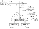
図2に示される負圧浄化モードにおいて、過給機52は使用可能ではない。また、機関11はインテークマニホルド22に負圧(負の圧力)を作成するために使用可能である。インテークマニホルド22の負圧は、機関11が引き込まれた燃料蒸気を燃焼するように、燃料蒸気捕捉容器18からキャニスタ通路管24を通して燃料蒸気を引き込む。負圧浄化モードでは、制御装置80は浄化バルブ26を開き、バイパス弁38を閉じる。さらに、ESM32の中の負圧スイッチは閉まっている。この状態は、逆止弁44が引き込まれ、閉じられる状態を生成し、この結果として、エジェクタ42からの気流を制限する。負圧浄化モードは、機関11および蒸発成分システム10の基礎的な作動モードである。
In the negative pressure purification mode shown in FIG. 2, the
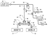
図3に示される加圧浄化モードでは、過給機52は運転状態に置かれている。さらに、制御装置80は浄化バルブ26を開き、バイパス弁38を閉じる。さらに、ESM32の中の負圧スイッチは閉まっている。過給機52の作動は、空気のインテークポート54から、過給機52を通り、インテークマニホルド22への空気流を生じさせ、これにより、インテークマニホルドの中へ高圧を生成する。逆止弁25は、高圧の提供により閉じられ、その結果、逆流を制限する。過給機52によって引き起こされた空気流は、供給通路管56、第2ポート48、ベンチュリ通路42a、および、エジェクタ42の第3ポート50を通り、リターン通路管58を通る空気流を引き起こす。言い換えると、エジェクタ42は、過給機52の下流から過給機52の上流への吸入空気流を引き込むように構成されている。エジェクタ42を通る空気流は、第1ポート46に負圧(負の圧力)を生成するように、ベンチュリ通路42aの中に圧力差を生成するベンチュリ管効果を生成する。この負圧は、燃料蒸気捕捉容器18から、キャニスタ通路管24、浄化バルブ26、エジェクタ通路管40、逆止弁44、および、負圧通路管55を通って、エジェクタ42の中へ入るように、燃料蒸気を流れさせる。このように、燃料蒸気捕捉容器18からの燃料蒸気は、第1ポート46、ベンチュリ通路42a、エジェクタ42の第3ポート50、および、リターン通路管58を通って、過給機52の上流に供給される。供給された燃料蒸気は、過給機52によってインテークマニホルド22に引かれ、機関11の中で燃焼される。
In the pressure purification mode shown in FIG. 3, the
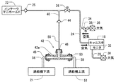
図4に示されるESMテストモードでは、機関11は運転中ではない。すなわち、ESMテストモードはキーオフ状態である。キーオフ状態で、ESM32の中の負圧スイッチは、機関11の運転期間の後の残留負圧によって閉じられている。したがって、ESM32は換気通路28を密閉する。蒸発成分システム10に漏洩がない場合、蒸発成分システム10内、すなわち燃料蒸気捕捉容器18内の圧力は、運転中の温度からの温度低下、または毎日の外気の温度サイクルの間中の温度低下のどちらかにより、負圧になる。負の圧力が蒸発成分システム10内に存在する場合、制御装置80は浄化バルブ26を閉じて、ESM32の機能性の試験を始めるためにバイパス弁38をそのために開く。バイパス弁38の開弁は、フィルタ36および負圧バイパス通路管34を通って燃料蒸気捕捉容器18の中に入り、燃料蒸気捕捉容器18の中の負圧を取り除かせる空気流を生じさせる。
In the ESM test mode shown in FIG. 4, the
典型的な実施形態では、バイパス弁38が開かれた後、燃料蒸気捕捉容器中の負圧が所定のレベルに到達する時に、ESM32の負圧スイッチが閉から開へ切り替わるかどうかを示す信号を制御装置80は受け取るように構成されている。信号が、ESM32の負圧スイッチが閉から開へ切り替えられたことを示す場合、制御装置80は、ESM32が適切に機能すると判断する。もし、ESM32が開へ切り替わらない場合、制御装置80はESM32が不調を持っていると判断する。故障の場合には、制御装置80は、システムを修理するように占有者に促すために機能不調インジケータを活性化してもよい。制御装置は、上述のようなESMの機能性のテストのために非遷移的なコンピュータ読取り可能な記録媒体備えていてもよい。
In an exemplary embodiment, after the
図1に戻り、圧力センサ60は、エジェクタ通路との連通のためにエジェクタ通路に装備されており、エジェクタ通路の圧力を検出するように構成されている。この第1実施形態によれば、圧力センサ60はリターン通路管58に装備されており、リターン通路管58と流体的に連通されている。
Returning to FIG. 1, the
上述のように、加圧浄化モードでは、浄化バルブ26は開く。また、過給機52は、燃料蒸気捕捉容器18から、エジェクタ42の中へ、燃料蒸気を引き出すために作動させられている。このように、燃料蒸気捕捉容器18からの燃料蒸気は、リターン通路管58を通ってインテークパイプ53の中への流れるために、エジェクタ42に引き込まれる。圧力センサ60は、リターン通路管58を通り抜ける、引き込まれた燃料蒸気の圧力に適用されている。
As described above, in the pressure purification mode, the
図1および図5は、故障のない標準状態における蒸発成分システム10を示す。図1および図5に示されるように、機関11が作動している時、機関11の4本のシリンダの各々は4ストローク動作を実行する。それは、吸気行程、圧縮行程、燃焼行程、および、排気行程を含んでいる。4本のシリンダは、異なるタイミングで4ストローク動作を実行し、それによって、異なるタイミングで吸入空気の圧力に脈動を引き起こす。脈動は、インテークマニホルド22、インテークパイプ21、および供給通路管56を通り、エジェクタ42の中へ伝搬する。脈動は、さらに第2ポート48、ベンチュリ通路42a、第3ポート50、およびリターン通路管58を通り、圧力センサ60の中へ伝搬する。したがって、圧力センサ60は、機関11の4本のシリンダから伝搬してきた脈動を検出する。
1 and 5 show the
図6は、蒸発成分システム10の故障状態の一例を示す。故障は、供給通路管56、エジェクタ42、および/またはリターン通路管58の間における接続機の外れによって引き起こされることがある。代替的に、または追加的に、故障は、リターン通路管58の破損によって引き起こされることがある。一例において、破損を通して燃料蒸気を漏らすような破損がリターン通路管58に生じる。この状態で、リターン通路管58中の燃料蒸気は、圧力センサ60へ脈動を伝搬するにはそれほど有効ではない。したがって、標準状態における脈動と比較して、圧力センサ60に伝搬した脈動はそれほど強くはない。故障は、供給通路管56の破損によって引き起こされてもよい。この場合、供給通路管56中の燃料蒸気は、リターン通路管58を通して、圧力センサ60へ脈動を伝搬するにはそれほど有効ではない。したがって、この場合でさえ、標準状態における脈動と比較して、圧力センサ60に伝搬した脈動はそれほど強くはない。
FIG. 6 shows an example of a failure state of the
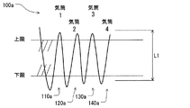
図7および図8の各々は、圧力センサ60によって検出された脈動の例を示している。この例において、検出された脈動は、機関11の4つの気筒である第1シリンダ、第2シリンダ、第3シリンダ、および第4シリンダに対応する4つのパルスを含めるために単純化されている。この例において、パルスの各々は、V字形のパルスであり、上部のピーク、下部のピーク、およびそれらの間の振幅を有する。実際の脈動は、様々な次数の様々な波の集合であり、さらに複雑な形状である。
Each of FIG. 7 and FIG. 8 shows an example of pulsation detected by the
図7は、標準状態における脈動100aの一例を示す。特に、標準状態では、供給通路管56、エジェクタ42、および/またはリターン通路管58に故障はなく、本質的に漏洩を引き起こすことはない。標準状態において、各々のパルス110a、120a、130a、140aは、振幅を有し、それは振幅L1に関係している。さらに、パルス110a、120a、130a、140aの各々は上限より大きな上部のピークを有する。さらに、パルス110a、120a、130a、140aの各々は下限未満の下部のピークを有する。
FIG. 7 shows an example of the
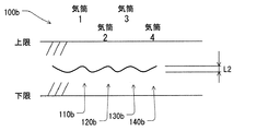
図8は、故障状態における脈動100bの一例を示す。故障状態において、脈動は、漏洩によって減衰させられ、減少させられている。この例では、故障状態において、パルス110b、120b、130b、140bの各々は振幅を有し、それは振幅L2に関係している。振幅L2は振幅L1未満である。故障モードにおいて、パルス110b、120b、130b、140bの各々は上限未満の上部のピークを有する。さらに、パルス110b、120b、130b、140bの各々には下限値より大きな下部のピークを有する。
FIG. 8 shows an example of the
圧力センサ60は、脈動を検出し、制御装置80に検出された脈動を示す検出信号を送る。制御装置80は、検出信号を受け取り、検出信号によって、現状が標準状態、または、故障状態かどうかを判断する。
The
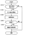
図9において、続いて、故障状態を決定するための故障決定処理の一例が説明される。処理は、例えば、ソフトウェアプログラムとしてコード化され、制御装置80の記憶装置(非遷移的なコンピュータ読取り可能な記録媒体)に格納されてもよい。処理は、1秒のような所定間隔で制御装置80によって実行される。
In FIG. 9, an example of a failure determination process for determining a failure state will be described. For example, the process may be encoded as a software program and stored in a storage device (non-transitional computer-readable recording medium) of the
S110では、制御装置80は、現在のモードが加圧浄化モードかどうかを判断する。S110において肯定的に判定されると、制御装置80は、S120で、圧力センサ60からの検出された圧力のサンプリングを開始する。
In S110, the
続いて、S130では、制御装置80は、サンプリングされた検出圧力によって、現状が標準状態または故障状態かどうかを判断する。具体的には、制御装置80は、脈動の振幅が振幅閾値未満である状態であれば、現状が故障状態であると決定する。現状が標準状態または故障状態かどうかの決定は、脈動の上部のピークが上限未満であるかどうかの追加的決定、および/または、脈動の下部のピークが下限を上回るかどうかの追加的決定を、さらに、考慮して実行されてもよい。
Subsequently, in S <b> 130, the
例えば、機関が低い負荷で運転されているとき、それに従って、脈動の振幅は小さくなってもよい。代替的に、機関が高い負荷で運転中である場合、それに従って、脈動の振幅は高くなってもよい。したがって、制御装置80は、様々な機関運転状況に対応する振幅閾値の様々な値を区画形成するデータマップを格納し、現状の機関の運転状況に応じた適切なひとつの値を使用してもよい。振幅は、脈動の中の複数のパルスの振幅から抽出された少なくともひとつの代表的な振幅でもよい。さらに、制御装置80は、様々な危難運転状況に対応する上限および/または下限の様々な値を定義するデータマップを格納してもよい。データマップは、様々な機関の運転状況の下における脈動の形状を実際に計測することによって得られてもよい。
For example, when the engine is operating at a low load, the pulsation amplitude may decrease accordingly. Alternatively, if the engine is operating at high load, the pulsation amplitude may increase accordingly. Therefore, the
S140では、現在の状態が故障状態であることを制御装置80が決定する場合、制御装置80は機能不調処理を実行してもよい。例えば、故障状態の場合には、制御装置80は、システムを修理するように占有者に促すために機能不調インジケータを活性化してもよい。制御装置80は記憶装置に故障状態を格納してもよい。制御装置80は、データセンターのような外部施設に故障状態を表わす情報を送信してもよい。制御装置80は、燃料蒸気の漏洩を制限するか縮小するために機関11の能力を制限してもよいし縮小してもよい。
In S140, when the
上記のように、この実施形態によると、圧力センサ60が、エジェクタ42の下流側のリターン通路管58に装着される。さらに、制御装置80は圧力センサ60から送られた検出信号によって故障モードが生じるかどうか判断するように構成される。したがって、このシステムは、燃料蒸気捕捉容器18からの蒸気の漏洩が、エジェクタ42および/またはリターン通路管58の外れおよび/または破損により生じたことの決定を可能にする。
As described above, according to this embodiment, the
S130の決定では、脈動は、機関の運転状態、シリンダ特性の変化、および/または、気候、または道路状況のような外部要因、および/または、蒸発成分システム10以外の外部装置の状態のような様々な要因に依存して、異なることがある。したがって、故障状態の決定のための様々な条件は様々な要因を考慮して採用されることがある。
In the determination of S130, the pulsation is such as engine operating conditions, changes in cylinder characteristics, and / or external factors such as climate or road conditions, and / or conditions of external devices other than the
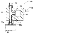
以下のように、この第1実施形態による圧力センサ60の構造の一例が説明される。図10に示されるように、圧力センサ60はマニホルド通路管62を持つボディ68を有しており、圧力センサエレメント66を収容している。圧力センサエレメント66は、検出ポート64を通して、マニホルド通路管62に流体的に連結されている。圧力センサエレメント66は、マニホルド通路管62の圧力を検出し、かつ検出された圧力によって電気信号を生成するように構成されている。この例において、圧力センサエレメント66はダイヤフラム式センサである。圧力センサエレメント66は、ワイヤ抵抗歪みゲージ、容量性変換器、および/または、ピエゾ半導体変換器のような様々な構成を採用することができる。圧力センサエレメント66は、電気的な配線70と電気的に接続されている。電気的な配線70は、制御装置80に電気的に接続されている。したがって、制御装置80は検出された圧力を得るために、圧力センサエレメント66から検出信号として電気信号をそのために受け取るように構成されている。
An example of the structure of the
マニホルド通路管62は、その一端側(図中において上側)に、その外部の周囲の上にぎざぎざがつけられたカプラを持っている。また、ぎざぎざがつけられたカプラは、リターン通路管58と連結されている。リターン通路管58は、その外部の周囲の上に、円形のクリップを装備している。このように、マニホルド通路管62は、リターン通路管58と流体的に連結されている。マニホルド通路管62は、さらに、他端側(図面中において下側)に、その外部の周囲にねじが形成されたカプラを持っている。また、ねじが形成されたカプラは、インテークパイプ53の圧力タップ53aに、ナット53bを用いて連結されている。このように、マニホルド通路管62は、インテークパイプ53と流体的に連結されている。この例において、圧力センサ60は、検出ユニット、流体的な接続ユニット、および、電気的な配線装置を持っている統合化モジュールである。
The
マニホルド通路管62は、リターン通路管58にねじで留められてもよく、および/または、インテークパイプ53に、ぎざぎざがつけられたカプラによって接続されていてもよい。マニホルド通路管62は、ナット53bなしで、インテークパイプ53に直接的にねじで留められてもよい。
The
この構成では、圧力センサエレメント66は、インテークパイプ53へ向かう、エジェクタ42の第3ポート50から、および、リターン通路管58からの、燃料蒸気および/または空気流を導くマニホルド通路管62の中の圧力を検出するように構成されている。
In this configuration, the
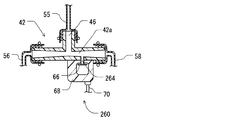
(第2実施形態)
図11に示されるように、この第2実施形態によると、圧力センサ260は統合化されたモジュールを形成するようにエジェクタ42と統合化されている。具体的には、エジェクタ42はベンチュリ通路42aを持っている。それは検知ポート264を形成するために内部で枝分かれさせられている。圧力センサエレメント66は、検出ポート264へ装備されており、ベンチュリ通路42aの圧力を検出するように構成されている。この構成では、圧力センサエレメント66は、機関11で引き起こされた脈動を検出するように構成されていてもよい。
(Second Embodiment)
As shown in FIG. 11, according to this second embodiment, the
例えば、故障は、エジェクタ42、および/または、リターン通路管58の外れ、および/または、破損によって生じる。リターン通路管58に外れ、および/または、破損が生じた場合、圧力センサ260で検知された脈動は、圧力センサ260の下流での故障によって、減少する。
For example, the failure may be caused by the
(第3実施形態)
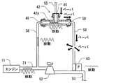
図12に示されるように、この第3実施形態によると、圧力センサ360は供給通路管56に装備されている。圧力センサ360は、第1実施形態と同様に圧力センサモジュールの構成を採用することができる。また、圧力センサ360は、過給機52の下流側において、供給通路管56とインテークパイプ21との間に連結されていてもよい。
(Third embodiment)
As shown in FIG. 12, according to the third embodiment, the
エジェクタ42、および/または、リターン通路管58に外れ、および/または、破損が生じた場合、圧力センサ360で検知された脈動は、圧力センサ360の下流での故障によって、減少する。
When the
(他の実施形態)
圧力センサは、統合化されたモジュールに限定されない。第1実施形態では、リターン通路管58は、圧力センサ60の検出ポートにつながる追加的通路へ、リターン通路管58をそこを通して枝分かれさせるために、T型管(三方通路)を装備していてもよい。第2実施形態では、エジェクタ42は、圧力センサ260の検出ポートにつながる追加的通路へ、ベンチュリ通路42aをそこを通して枝分かれさせるために、T型管(三方通路)を装備していてもよい。第1実施形態では、供給通路管56は、圧力センサ360の検出ポートにつながる追加的通路へ、供給通路管56をそこを通して枝分かれさせるために、T型管(三方通路)を装備していてもよい。すなわちこれらの例において、圧力センサは追加的通路に装備されていてもよい。
(Other embodiments)
The pressure sensor is not limited to an integrated module. In the first embodiment, the
上記の実施形態中の蒸発成分システムの構成部品の材料は、例示であって、樹脂、ゴム、および/または金属のような様々な材料から選ばれてもよい。 The materials of the components of the evaporative component system in the above embodiments are exemplary and may be selected from various materials such as resin, rubber, and / or metal.
この開示の実施形態の処理は、複数のステップの特定の順序を含むものとしてここでは説明されているが、それらのステップのいくつかの他の順序、および/または、ここに説明されない追加的なステップを含むさらに代替的な実施形態が、この開示の複数のステップの中にあるように意図されていると解されるべきである。 Although the processes of the embodiments of this disclosure are described herein as including a particular order of steps, some other order of those steps and / or additional steps not described herein It should be understood that further alternative embodiments including steps are intended to be among the steps of this disclosure.
この開示は、その複数の好ましい実施形態を参照することによって説明されているが、この開示は好ましい実施形態および構成に限定されないものと理解されるべきである。この開示は、多様な変形例と、均等の構成とを包含することを意図している。加えて、多様な組み合わせおよび構成が望ましいが、さらに多くの、さらに少ない、またはたったひとつの要素を含む他の組み合わせおよび構成もまた、この開示の要旨および範囲の中にある。 While this disclosure has been described with reference to a plurality of preferred embodiments thereof, it is to be understood that this disclosure is not limited to the preferred embodiments and configurations. This disclosure is intended to cover various modifications and equivalent arrangements. In addition, although various combinations and configurations are desirable, other combinations and configurations that include more, fewer, or just one element are also within the spirit and scope of this disclosure.
Claims (9)
前記過給機(52)の上流へ燃料蒸気を引き込むための負圧を生成するために、前記過給機(52)の下流から、前記過給機(52)の上流に前記吸入空気の流れを引くように構成されたエジェクタ(42)と、
前記過給機(52)の下流から分岐し、前記過給機(52)の上流に前記エジェクタ(42)を通して戻されるエジェクタ通路(56、42a、58)と、
前記エジェクタ通路(56、42a、58)に連通しており、前記エジェクタ通路(56、42a、58)の圧力を検出するように構成された圧力センサ(60、260、360)と、
前記燃料蒸気を吸収するように、かつ前記エジェクタ(42)に前記燃料蒸気を供給するように構成されている燃料蒸気捕捉容器(18)とを備え、
前記エジェクタ(42)は、第1ポート(46)、第2ポート(48)および第3ポート(50)を有し、
前記第1ポート(46)は前記燃料蒸気捕捉容器(18)と流体的に連通しており、
前記第2ポート(48)は前記過給機(52)の下流と流体的に連通しており、
前記第3ポート(50)は前記過給機(52)の上流に流体的に連通しており、
前記エジェクタ(42)は前記第2ポート(48)と前記第3ポート(50)との間で、前記エジェクタ通路(56、42a、58)の一部であるベンチュリ通路(42a)を形成しており、
前記圧力センサ(60)は、前記第3ポート(50)と前記過給機(52)の上流との間の通路に流体的に連通しており、
さらに、前記圧力センサ(60、260、360)で検知された圧力を表わす情報を取得するために前記圧力センサ(60、260、360)と接続された制御装置(80)を備え、
前記制御装置(80)は、検知された圧力中の前記内燃機関のシリンダから伝搬してきた脈動についての情報を取得し、かつ前記脈動についての情報によって前記エジェクタ通路(56、42a、58)における漏洩を決定するように構成されている蒸発成分システム。 An evaporative component system for an internal combustion engine (11), said internal combustion engine comprising an intake pipe (21) comprising a supercharger (52) for pressurizing intake air,
The flow of the intake air from the downstream of the supercharger (52) to the upstream of the supercharger (52) in order to generate a negative pressure for drawing fuel vapor upstream of the supercharger (52) An ejector (42) configured to pull
An ejector passage (56, 42a, 58) branched from the downstream of the supercharger (52) and returned through the ejector (42) upstream of the supercharger (52);
A pressure sensor (60, 260, 360) in communication with the ejector passage (56, 42a, 58) and configured to detect a pressure in the ejector passage (56, 42a, 58);
A fuel vapor capture vessel (18) configured to absorb the fuel vapor and to supply the fuel vapor to the ejector (42);
The ejector (42) has a first port (46), a second port (48) and a third port (50);
The first port (46) is in fluid communication with the fuel vapor capture vessel (18);
The second port (48) is in fluid communication with the downstream of the supercharger (52);
The third port (50) is in fluid communication upstream of the supercharger (52);
The ejector (42) forms a venturi passage (42a) which is a part of the ejector passage (56, 42a, 58) between the second port (48) and the third port (50). And
The pressure sensor (60) is in fluid communication with a passage between the third port (50) and the upstream of the supercharger (52) ;
And a control device (80) connected to the pressure sensor (60, 260, 360) for obtaining information representing the pressure detected by the pressure sensor (60, 260, 360),
The control device (80) acquires information on pulsation propagating from the cylinder of the internal combustion engine in the detected pressure, and leaks in the ejector passage (56, 42a, 58) according to the information on the pulsation. An evaporative component system that is configured to determine a .
前記過給機(52)の上流へ燃料蒸気を引き込むための負圧を生成するために、前記過給機(52)の下流から、前記過給機(52)の上流に前記吸入空気の流れを引くように構成されたエジェクタ(42)と、
前記過給機(52)の下流から分岐し、前記過給機(52)の上流に前記エジェクタ(42)を通して戻されるエジェクタ通路(56、42a、58)と、
前記エジェクタ通路(56、42a、58)に連通しており、前記エジェクタ通路(56、42a、58)の圧力を検出するように構成された圧力センサ(60、260、360)と、
前記燃料蒸気を吸収するように、かつ前記エジェクタ(42)に前記燃料蒸気を供給するように構成されている燃料蒸気捕捉容器(18)とを備え、
前記エジェクタ(42)は、第1ポート(46)、第2ポート(48)および第3ポート(50)を有し、
前記第1ポート(46)は前記燃料蒸気捕捉容器(18)と流体的に連通しており、
前記第2ポート(48)は前記過給機(52)の下流と流体的に連通しており、
前記第3ポート(50)は前記過給機(52)の上流に流体的に連通しており、
前記エジェクタ(42)は前記第2ポート(48)と前記第3ポート(50)との間で、前記エジェクタ通路(56、42a、58)の一部であるベンチュリ通路(42a)を形成しており、
前記圧力センサ(260)は、前記エジェクタ(42)に統合されており、前記ベンチュリ通路(42a)に流体的に連通しており、
さらに、前記圧力センサ(60、260、360)で検知された圧力を表わす情報を取得するために前記圧力センサ(60、260、360)と接続された制御装置(80)を備え、
前記制御装置(80)は、検知された圧力中の前記内燃機関のシリンダから伝搬してきた脈動についての情報を取得し、かつ前記脈動についての情報によって前記エジェクタ通路(56、42a、58)における漏洩を決定するように構成されている蒸発成分システム。 An evaporative component system for an internal combustion engine (11), said internal combustion engine comprising an intake pipe (21) comprising a supercharger (52) for pressurizing intake air,
The flow of the intake air from the downstream of the supercharger (52) to the upstream of the supercharger (52) in order to generate a negative pressure for drawing fuel vapor upstream of the supercharger (52) An ejector (42) configured to pull
An ejector passage (56, 42a, 58) branched from the downstream of the supercharger (52) and returned through the ejector (42) upstream of the supercharger (52);
A pressure sensor (60, 260, 360) in communication with the ejector passage (56, 42a, 58) and configured to detect a pressure in the ejector passage (56, 42a, 58);
A fuel vapor capture vessel (18) configured to absorb the fuel vapor and to supply the fuel vapor to the ejector (42);
The ejector (42) has a first port (46), a second port (48) and a third port (50);
The first port (46) is in fluid communication with the fuel vapor capture vessel (18);
The second port (48) is in fluid communication with the downstream of the supercharger (52);
The third port (50) is in fluid communication upstream of the supercharger (52);
The ejector (42) forms a venturi passage (42a) which is a part of the ejector passage (56, 42a, 58) between the second port (48) and the third port (50). And
The pressure sensor (260) is integrated into the ejector (42) and is in fluid communication with the venturi passage (42a) ,
And a control device (80) connected to the pressure sensor (60, 260, 360) for obtaining information representing the pressure detected by the pressure sensor (60, 260, 360),
The control device (80) acquires information on pulsation propagating from the cylinder of the internal combustion engine during the detected pressure, and leaks in the ejector passage (56, 42a, 58) according to the information on the pulsation. An evaporative component system that is configured to determine a .
前記過給機(52)の上流へ燃料蒸気を引き込むための負圧を生成するために、前記過給機(52)の下流から、前記過給機(52)の上流に前記吸入空気の流れを引くように構成されたエジェクタ(42)と、
前記過給機(52)の下流から分岐し、前記過給機(52)の上流に前記エジェクタ(42)を通して戻されるエジェクタ通路(56、42a、58)と、
前記エジェクタ通路(56、42a、58)に連通しており、前記エジェクタ通路(56、42a、58)の圧力を検出するように構成された圧力センサ(60、260、360)と、
前記燃料蒸気を吸収するように、かつ前記エジェクタ(42)に前記燃料蒸気を供給するように構成されている燃料蒸気捕捉容器(18)とを備え、
前記エジェクタ(42)は、第1ポート(46)、第2ポート(48)および第3ポート(50)を有し、
前記第1ポート(46)は前記燃料蒸気捕捉容器(18)と流体的に連通しており、
前記第2ポート(48)は前記過給機(52)の下流と流体的に連通しており、
前記第3ポート(50)は前記過給機(52)の上流に流体的に連通しており、
前記エジェクタ(42)は前記第2ポート(48)と前記第3ポート(50)との間で、前記エジェクタ通路(56、42a、58)の一部であるベンチュリ通路(42a)を形成しており、
前記圧力センサ(360)は、前記第2ポート(48)と前記過給機(52)の下流との間の通路に流体的に連通しており、
さらに、前記圧力センサ(60、260、360)で検知された圧力を表わす情報を取得するために前記圧力センサ(60、260、360)と接続された制御装置(80)を備え、
前記制御装置(80)は、検知された圧力中の前記内燃機関のシリンダから伝搬してきた脈動についての情報を取得し、かつ前記脈動についての情報によって前記エジェクタ通路(56、42a、58)における漏洩を決定するように構成されている蒸発成分システム。 An evaporative component system for an internal combustion engine (11), said internal combustion engine comprising an intake pipe (21) comprising a supercharger (52) for pressurizing intake air,
The flow of the intake air from the downstream of the supercharger (52) to the upstream of the supercharger (52) in order to generate a negative pressure for drawing fuel vapor upstream of the supercharger (52) An ejector (42) configured to pull
An ejector passage (56, 42a, 58) branched from the downstream of the supercharger (52) and returned through the ejector (42) upstream of the supercharger (52);
A pressure sensor (60, 260, 360) in communication with the ejector passage (56, 42a, 58) and configured to detect a pressure in the ejector passage (56, 42a, 58);
A fuel vapor capture vessel (18) configured to absorb the fuel vapor and to supply the fuel vapor to the ejector (42);
The ejector (42) has a first port (46), a second port (48) and a third port (50);
The first port (46) is in fluid communication with the fuel vapor capture vessel (18);
The second port (48) is in fluid communication with the downstream of the supercharger (52);
The third port (50) is in fluid communication upstream of the supercharger (52);
The ejector (42) forms a venturi passage (42a) which is a part of the ejector passage (56, 42a, 58) between the second port (48) and the third port (50). And
The pressure sensor (360) is in fluid communication with a passage between the second port (48) and a downstream of the supercharger (52) ;
And a control device (80) connected to the pressure sensor (60, 260, 360) for obtaining information representing the pressure detected by the pressure sensor (60, 260, 360),
The control device (80) acquires information on pulsation propagating from the cylinder of the internal combustion engine in the detected pressure, and leaks in the ejector passage (56, 42a, 58) according to the information on the pulsation. An evaporative component system that is configured to determine a .
前記浄化バルブ(26)は、選択的に、前記燃料蒸気捕捉容器(18)を前記第1ポート(46)に連通し、かつ前記燃料蒸気捕捉容器(18)を前記第1ポート(46)から遮断するように構成されている請求項1から請求項5のいずれかひとつに記載の蒸発成分システム。 And a purification valve (26) positioned between the fuel vapor capture container (18) and the first port (46),
The purification valve (26) optionally communicates the fuel vapor capture container (18) to the first port (46) and connects the fuel vapor capture container (18) from the first port (46). The evaporative component system according to any one of claims 1 to 5 , wherein the evaporative component system is configured to be shut off.
前記第1逆止弁(44)は、前記エジェクタ(42)から前記燃料蒸気捕捉容器(18)へ逆流する蒸気を制限するように構成される請求項6に記載の蒸発成分システム。 And a first check valve (44) positioned between the first port (46) and the purification valve (26),
The evaporative component system according to claim 6 , wherein the first check valve (44) is configured to restrict steam flowing back from the ejector (42) to the fuel vapor capture container (18).
前記第2の逆止弁(25)は、前記インテークパイプ(21)から前記燃料蒸気捕捉容器(18)へ逆流する蒸気を制限するように構成されている請求項6または請求項7に記載の蒸発成分システム。 And a second check valve (25) positioned between the intake pipe (21) and the purification valve (26),
The second check valve (25) according to claim 6 or 7 , wherein the second check valve (25) is configured to restrict steam flowing back from the intake pipe (21) to the fuel vapor trapping container (18). Evaporative component system.
前記バイパス弁(38)は、選択的に、前記燃料蒸気捕捉容器(18)を大気に連通し、かつ前記燃料蒸気捕捉容器(18)を大気から遮断するように構成されている請求項6から請求項8のいずれかひとつに記載の蒸発成分システム。 And a bypass valve (38) positioned between the purification valve (26) and the fuel vapor capture vessel (18),
It said bypass valve (38) is optionally the fuel vapor capturing container (18) communicates with the atmosphere, and the fuel vapor capturing container (18) from claim 6 is configured to cut off from the atmosphere The evaporative component system according to claim 8 .
Applications Claiming Priority (5)
| Application Number | Priority Date | Filing Date | Title |
|---|---|---|---|
| US201462048567P | 2014-09-10 | 2014-09-10 | |
| US62/048,567 | 2014-09-10 | ||
| US14/678,241 US10060394B2 (en) | 2014-09-10 | 2015-04-03 | Evaporative system |
| US14/678,241 | 2015-04-03 | ||
| PCT/JP2015/004508 WO2016038864A1 (en) | 2014-09-10 | 2015-09-04 | Evaporative system |
Publications (2)
| Publication Number | Publication Date |
|---|---|
| JP2017521598A JP2017521598A (en) | 2017-08-03 |
| JP6350737B2 true JP6350737B2 (en) | 2018-07-04 |
Family
ID=55437110
Family Applications (1)
| Application Number | Title | Priority Date | Filing Date |
|---|---|---|---|
| JP2017501345A Expired - Fee Related JP6350737B2 (en) | 2014-09-10 | 2015-09-04 | Evaporation component system |
Country Status (5)
| Country | Link |
|---|---|
| US (1) | US10060394B2 (en) |
| JP (1) | JP6350737B2 (en) |
| CN (1) | CN107076061B (en) |
| DE (1) | DE112015004138T5 (en) |
| WO (1) | WO2016038864A1 (en) |
Families Citing this family (26)
| Publication number | Priority date | Publication date | Assignee | Title |
|---|---|---|---|---|
| EP2823981B1 (en) * | 2013-07-12 | 2021-09-08 | Plastic Omnium Advanced Innovation and Research | Vehicle storage system with vapour control |
| JP6354734B2 (en) * | 2015-11-16 | 2018-07-11 | 株式会社デンソー | Abnormality detection device for internal combustion engine |
| US9643674B1 (en) * | 2015-12-04 | 2017-05-09 | Honda Motor Co., Ltd. | Motorcycle |
| JP6315002B2 (en) * | 2016-02-04 | 2018-04-25 | トヨタ自動車株式会社 | Purge device |
| US10150365B2 (en) * | 2016-09-14 | 2018-12-11 | Ford Global Technologies, Llc | Systems and methods for coordinating remote fuel delivery to vehicles |
| DE102016121900A1 (en) * | 2016-11-15 | 2018-05-17 | Dr. Ing. H.C. F. Porsche Aktiengesellschaft | Method for diagnosing a tank venting valve |
| EP3339621B1 (en) | 2016-12-22 | 2020-04-01 | Ningbo Geely Automobile Research & Development Co. Ltd. | Purge ejector assembly for an engine |
| JP6601434B2 (en) * | 2017-02-13 | 2019-11-06 | トヨタ自動車株式会社 | Evaporative fuel processing equipment |
| US10145339B1 (en) * | 2017-09-19 | 2018-12-04 | Ford Global Technologies, Llc | Systems and method for a self disabling ejector of an air induction system |
| DE102017216728B3 (en) | 2017-09-21 | 2018-12-20 | Continental Automotive Gmbh | Method and device for controlling a tank venting valve connected via two flushing lines to the intake tract of a turbocharged internal combustion engine |
| JP6969435B2 (en) * | 2018-02-22 | 2021-11-24 | トヨタ自動車株式会社 | Evaporative fuel processing equipment |
| US20190323924A1 (en) * | 2018-04-20 | 2019-10-24 | Kai-Ee Inc. | Testing device for vehicles |
| KR20190131947A (en) | 2018-05-18 | 2019-11-27 | 현대자동차주식회사 | Diagnostic apparatus and method for diagnising active canister purge systme |
| DE102018212149A1 (en) * | 2018-07-20 | 2020-01-23 | Volkswagen Aktiengesellschaft | Internal combustion engine with a Venturi nozzle provided in a fluid-carrying component that is fluidly connected to a tank ventilation line |
| JP6946244B2 (en) * | 2018-09-05 | 2021-10-06 | 愛三工業株式会社 | Evaporative fuel processing equipment |
| JP7067411B2 (en) * | 2018-10-16 | 2022-05-16 | トヨタ自動車株式会社 | Evaporative fuel processing equipment |
| KR102633947B1 (en) * | 2018-11-05 | 2024-02-05 | 현대자동차주식회사 | Fuel vapor gas purge system |
| US10774761B2 (en) * | 2018-11-13 | 2020-09-15 | Ford Global Technologies, Llc | Systems and methods for reducing vehicle valve degradation |
| DE102018130676A1 (en) * | 2018-12-03 | 2020-06-04 | Volkswagen Aktiengesellschaft | Method for tank ventilation of a fuel tank of a vehicle, device for tank ventilation of a fuel tank of a vehicle |
| KR102136800B1 (en) * | 2019-04-15 | 2020-07-22 | 주식회사 현대케피코 | Dual pruge ejector and manufacturing method thereof |
| KR102180184B1 (en) * | 2019-12-09 | 2020-11-18 | 주식회사 현대케피코 | Dual purge device of vehicle |
| DE102020200038B4 (en) | 2020-01-06 | 2022-06-15 | Volkswagen Aktiengesellschaft | Internal combustion engine with a venturi nozzle provided in a fluid-carrying component fluidly connected to a tank ventilation line, and method for determining a leak in a fluid-carrying component of such an internal combustion engine |
| JP7338541B2 (en) * | 2020-04-14 | 2023-09-05 | トヨタ自動車株式会社 | engine device |
| JP7272325B2 (en) * | 2020-06-15 | 2023-05-12 | トヨタ自動車株式会社 | engine device |
| US11225935B1 (en) * | 2021-01-29 | 2022-01-18 | Ford Global Technologies, Llc | Dual path purge system for a turbocharged engine |
| CN121024801A (en) * | 2025-10-28 | 2025-11-28 | 恒力造船(大连)有限公司 | A high-pressure gas supply system combining high-pressure injection and reliquefaction functions |
Family Cites Families (31)
| Publication number | Priority date | Publication date | Assignee | Title |
|---|---|---|---|---|
| JPS6047462B2 (en) * | 1978-06-02 | 1985-10-22 | 株式会社日立製作所 | Intake air amount measuring device for electronically controlled fuel injection system |
| US4506594A (en) * | 1982-02-25 | 1985-03-26 | The Garrett Corporation | Fluid flow control apparatus and method |
| EP0777041B1 (en) * | 1995-11-25 | 2002-03-13 | Cummins Engine Company, Inc. | An internal combustion engine with an engine crankcase gas blow-by sensor and a method of evaluating performance of an internal combustion engine |
| US6742335B2 (en) * | 2002-07-11 | 2004-06-01 | Clean Air Power, Inc. | EGR control system and method for an internal combustion engine |
| EP1406005B1 (en) * | 2002-09-20 | 2006-04-19 | Ford Global Technologies, Inc. | Method and apparatus for monitoring a controllable valve |
| DE102006024211A1 (en) * | 2005-05-24 | 2007-01-25 | Denso Corp., Kariya | Ejector pump and ejector cycle device |
| US20070095400A1 (en) * | 2005-11-03 | 2007-05-03 | Parker-Hannifin Corporation | Shut-off valve system |
| JP2007303346A (en) * | 2006-05-10 | 2007-11-22 | Toyota Motor Corp | Ejector system for vehicle and control device |
| JP2009074518A (en) * | 2007-09-25 | 2009-04-09 | Honda Motor Co Ltd | Evaporative fuel processing equipment |
| JP2009180095A (en) * | 2008-01-29 | 2009-08-13 | Aisan Ind Co Ltd | Negative pressure generating device |
| JP5399106B2 (en) | 2008-03-28 | 2014-01-29 | 矢崎エナジーシステム株式会社 | Gas leak and gas appliance discrimination device, and gas leak and gas appliance discrimination method |
| US8312765B2 (en) * | 2009-03-06 | 2012-11-20 | Ford Global Technologies, Llc | Fuel vapor purging diagnostics |
| US7966996B1 (en) * | 2010-03-03 | 2011-06-28 | Ford Global Technologies, Llc | Vacuum supply system |
| DE102010064239A1 (en) * | 2010-12-28 | 2012-06-28 | Robert Bosch Gmbh | Venting system, in particular for a fuel tank |
| DE102011080521A1 (en) * | 2011-08-05 | 2013-02-07 | Robert Bosch Gmbh | Bleeding a fuel tank with the help of a turbocharger |
| DE102011084403A1 (en) * | 2011-10-13 | 2013-04-18 | Robert Bosch Gmbh | Tank ventilation system and method for its diagnosis |
| US20130133631A1 (en) * | 2011-11-30 | 2013-05-30 | Caterpillar Inc. | System to measure parameters of a particulate laden flow |
| JP5927979B2 (en) * | 2012-02-23 | 2016-06-01 | 浜名湖電装株式会社 | Evaporative fuel purge device |
| US8924133B2 (en) * | 2012-02-28 | 2014-12-30 | Chrysler Group Llc | Turbocharged engine canister system and diagnostic method |
| US8783231B2 (en) * | 2012-03-12 | 2014-07-22 | Ford Global Technologies, Llc | Venturi for vapor purge |
| US9074540B2 (en) * | 2012-04-19 | 2015-07-07 | Cummins Inc. | Exhaust gas recirculation systems with variable venturi devices |
| US9239034B2 (en) * | 2012-09-12 | 2016-01-19 | Ford Global Technologies, Llc | Ejector system for a vehicle |
| US10619534B2 (en) * | 2012-09-14 | 2020-04-14 | Ford Global Technologies, Llc | Crankcase integrity breach detection |
| US9068486B2 (en) * | 2012-09-14 | 2015-06-30 | Ford Global Technologies, Llc | Crankcase integrity breach detection |
| US9243595B2 (en) * | 2013-01-17 | 2016-01-26 | Ford Global Technologies, Llc | Multi-path purge ejector system |
| US9133796B2 (en) * | 2013-03-08 | 2015-09-15 | Ford Global Technologies, Llc | Multi-path purge ejector system |
| US9360125B2 (en) * | 2013-04-23 | 2016-06-07 | Continental Automotive Systems, Inc. | Turbo purge valve-check valve OBD vacuum relief |
| US10166961B2 (en) * | 2013-12-05 | 2019-01-01 | Ford Global Technologies, Llc | Vacuum scavenging in hybrid vehicles |
| US9605625B2 (en) * | 2013-12-19 | 2017-03-28 | Continental Automotive Systems, Inc. | High performance vacuum venturi pump |
| DE102014012427A1 (en) * | 2014-08-26 | 2016-03-03 | GM Global Technology Operations LLC (n. d. Ges. d. Staates Delaware) | Vapor return system of a fuel vapor collection tank |
| US9528473B2 (en) * | 2015-05-21 | 2016-12-27 | Ford Global Technologies, Llc | Method and system for diagnosing a purge ejector |
-
2015
- 2015-04-03 US US14/678,241 patent/US10060394B2/en not_active Expired - Fee Related
- 2015-09-04 WO PCT/JP2015/004508 patent/WO2016038864A1/en not_active Ceased
- 2015-09-04 JP JP2017501345A patent/JP6350737B2/en not_active Expired - Fee Related
- 2015-09-04 CN CN201580048176.7A patent/CN107076061B/en not_active Expired - Fee Related
- 2015-09-04 DE DE112015004138.9T patent/DE112015004138T5/en not_active Ceased
Also Published As
| Publication number | Publication date |
|---|---|
| DE112015004138T5 (en) | 2017-06-01 |
| JP2017521598A (en) | 2017-08-03 |
| CN107076061B (en) | 2019-11-29 |
| WO2016038864A1 (en) | 2016-03-17 |
| CN107076061A (en) | 2017-08-18 |
| US10060394B2 (en) | 2018-08-28 |
| US20160069304A1 (en) | 2016-03-10 |
Similar Documents
| Publication | Publication Date | Title |
|---|---|---|
| JP6350737B2 (en) | Evaporation component system | |
| US8924133B2 (en) | Turbocharged engine canister system and diagnostic method | |
| CN107532544B (en) | Internal combustion engine and method for detecting leaks in a crankcase ventilation system and/or a fuel tank ventilation system | |
| US8312765B2 (en) | Fuel vapor purging diagnostics | |
| US7810475B2 (en) | Fuel vapor purging diagnostics | |
| CN110273793A (en) | System and method for breather filter diagnosis | |
| US20110197862A1 (en) | Checking Functionality of Fuel Tank Vapor Pressure Sensor | |
| CN204299730U (en) | A kind of vehicle fuel oil evaporation discharging system | |
| CN107420230A (en) | Canister high load capacity desorption pipeline desorption flow diagnostic method | |
| JP2017078378A (en) | Diagnostic equipment | |
| US6530265B2 (en) | Small/gross leak check | |
| JP6354734B2 (en) | Abnormality detection device for internal combustion engine | |
| JP4640133B2 (en) | Evaporative fuel treatment device leak diagnosis device | |
| US20150330349A1 (en) | Method and apparatus for detecting leakage of fuel evaporative gas | |
| JP4552837B2 (en) | Evaporative fuel treatment device leak diagnosis device | |
| KR20200118298A (en) | Method and system for diagnosing fault of dual purge system | |
| KR101603612B1 (en) | Tank venting apparatus for a supercharged internal combustion engine and associated control method | |
| US11073112B2 (en) | Evaporative emission control system for a vehicle | |
| CN107636294B (en) | Box ventilation device and method for diagnosing box ventilation device | |
| KR20150130244A (en) | Method for diagnosing a tank ventilation valve | |
| US6327901B1 (en) | Purge monitor/switch rationality diagnostics | |
| US7431022B1 (en) | Evaporative emission canister purge actuation monitoring system | |
| JP2005299560A5 (en) | ||
| CN101323250A (en) | Vehicle fuel oil evaporation control system | |
| US9983088B2 (en) | Engine ventilation system diagnostics using pressure measurement |
Legal Events
| Date | Code | Title | Description |
|---|---|---|---|
| A521 | Request for written amendment filed |
Free format text: JAPANESE INTERMEDIATE CODE: A523 Effective date: 20170118 |
|
| A621 | Written request for application examination |
Free format text: JAPANESE INTERMEDIATE CODE: A621 Effective date: 20170118 |
|
| A131 | Notification of reasons for refusal |
Free format text: JAPANESE INTERMEDIATE CODE: A131 Effective date: 20171107 |
|
| A521 | Request for written amendment filed |
Free format text: JAPANESE INTERMEDIATE CODE: A523 Effective date: 20180109 |
|
| TRDD | Decision of grant or rejection written | ||
| A01 | Written decision to grant a patent or to grant a registration (utility model) |
Free format text: JAPANESE INTERMEDIATE CODE: A01 Effective date: 20180508 |
|
| A61 | First payment of annual fees (during grant procedure) |
Free format text: JAPANESE INTERMEDIATE CODE: A61 Effective date: 20180521 |
|
| R150 | Certificate of patent or registration of utility model |
Ref document number: 6350737 Country of ref document: JP Free format text: JAPANESE INTERMEDIATE CODE: R150 |
|
| R250 | Receipt of annual fees |
Free format text: JAPANESE INTERMEDIATE CODE: R250 |
|
| R250 | Receipt of annual fees |
Free format text: JAPANESE INTERMEDIATE CODE: R250 |
|
| LAPS | Cancellation because of no payment of annual fees |