JP6346858B2 - System and method for re-entering a blood vessel cavity - Google Patents
System and method for re-entering a blood vessel cavity Download PDFInfo
- Publication number
- JP6346858B2 JP6346858B2 JP2014518663A JP2014518663A JP6346858B2 JP 6346858 B2 JP6346858 B2 JP 6346858B2 JP 2014518663 A JP2014518663 A JP 2014518663A JP 2014518663 A JP2014518663 A JP 2014518663A JP 6346858 B2 JP6346858 B2 JP 6346858B2
- Authority
- JP
- Japan
- Prior art keywords
- catheter
- actuating member
- strut
- tubular member
- outer tubular
- Prior art date
- Legal status (The legal status is an assumption and is not a legal conclusion. Google has not performed a legal analysis and makes no representation as to the accuracy of the status listed.)
- Expired - Fee Related
Links
- 210000004204 blood vessel Anatomy 0.000 title claims description 28
- 238000000034 method Methods 0.000 title description 21
- 239000012528 membrane Substances 0.000 claims description 25
- 229910001000 nickel titanium Inorganic materials 0.000 claims description 11
- 230000015572 biosynthetic process Effects 0.000 claims description 3
- 230000003902 lesion Effects 0.000 description 21
- 229910000734 martensite Inorganic materials 0.000 description 17
- 229910001566 austenite Inorganic materials 0.000 description 15
- 230000007704 transition Effects 0.000 description 12
- 229910052751 metal Inorganic materials 0.000 description 10
- 239000002184 metal Substances 0.000 description 10
- 230000009467 reduction Effects 0.000 description 8
- 210000005166 vasculature Anatomy 0.000 description 8
- 239000000463 material Substances 0.000 description 6
- 229910045601 alloy Inorganic materials 0.000 description 5
- 239000000956 alloy Substances 0.000 description 5
- 208000019553 vascular disease Diseases 0.000 description 4
- 210000001367 artery Anatomy 0.000 description 3
- 230000017531 blood circulation Effects 0.000 description 3
- 238000010586 diagram Methods 0.000 description 3
- 238000010438 heat treatment Methods 0.000 description 3
- 230000000414 obstructive effect Effects 0.000 description 3
- 230000000149 penetrating effect Effects 0.000 description 3
- -1 polytetrafluoroethylene Polymers 0.000 description 3
- 239000004698 Polyethylene Substances 0.000 description 2
- 238000013461 design Methods 0.000 description 2
- 238000003384 imaging method Methods 0.000 description 2
- 238000012986 modification Methods 0.000 description 2
- 230000004048 modification Effects 0.000 description 2
- HLXZNVUGXRDIFK-UHFFFAOYSA-N nickel titanium Chemical compound [Ti].[Ti].[Ti].[Ti].[Ti].[Ti].[Ti].[Ti].[Ti].[Ti].[Ti].[Ni].[Ni].[Ni].[Ni].[Ni].[Ni].[Ni].[Ni].[Ni].[Ni].[Ni].[Ni].[Ni].[Ni] HLXZNVUGXRDIFK-UHFFFAOYSA-N 0.000 description 2
- 238000012014 optical coherence tomography Methods 0.000 description 2
- 229920000573 polyethylene Polymers 0.000 description 2
- 229920000642 polymer Polymers 0.000 description 2
- 230000002441 reversible effect Effects 0.000 description 2
- 239000000126 substance Substances 0.000 description 2
- 210000001519 tissue Anatomy 0.000 description 2
- 206010003210 Arteriosclerosis Diseases 0.000 description 1
- 208000037260 Atherosclerotic Plaque Diseases 0.000 description 1
- 241001631457 Cannula Species 0.000 description 1
- 208000024172 Cardiovascular disease Diseases 0.000 description 1
- 102000009123 Fibrin Human genes 0.000 description 1
- 108010073385 Fibrin Proteins 0.000 description 1
- BWGVNKXGVNDBDI-UHFFFAOYSA-N Fibrin monomer Chemical compound CNC(=O)CNC(=O)CN BWGVNKXGVNDBDI-UHFFFAOYSA-N 0.000 description 1
- 239000004677 Nylon Substances 0.000 description 1
- 239000004952 Polyamide Substances 0.000 description 1
- 208000007536 Thrombosis Diseases 0.000 description 1
- HZEWFHLRYVTOIW-UHFFFAOYSA-N [Ti].[Ni] Chemical compound [Ti].[Ni] HZEWFHLRYVTOIW-UHFFFAOYSA-N 0.000 description 1
- 238000009825 accumulation Methods 0.000 description 1
- WYTGDNHDOZPMIW-RCBQFDQVSA-N alstonine Natural products C1=CC2=C3C=CC=CC3=NC2=C2N1C[C@H]1[C@H](C)OC=C(C(=O)OC)[C@H]1C2 WYTGDNHDOZPMIW-RCBQFDQVSA-N 0.000 description 1
- 238000002399 angioplasty Methods 0.000 description 1
- 238000013459 approach Methods 0.000 description 1
- 230000009286 beneficial effect Effects 0.000 description 1
- 239000000560 biocompatible material Substances 0.000 description 1
- 230000008859 change Effects 0.000 description 1
- 230000001684 chronic effect Effects 0.000 description 1
- 239000002131 composite material Substances 0.000 description 1
- 238000010276 construction Methods 0.000 description 1
- 238000007796 conventional method Methods 0.000 description 1
- 238000007887 coronary angioplasty Methods 0.000 description 1
- 210000004351 coronary vessel Anatomy 0.000 description 1
- 230000000881 depressing effect Effects 0.000 description 1
- 201000010099 disease Diseases 0.000 description 1
- 208000037265 diseases, disorders, signs and symptoms Diseases 0.000 description 1
- 210000003038 endothelium Anatomy 0.000 description 1
- 210000001105 femoral artery Anatomy 0.000 description 1
- 229950003499 fibrin Drugs 0.000 description 1
- 238000002594 fluoroscopy Methods 0.000 description 1
- 238000013152 interventional procedure Methods 0.000 description 1
- 238000002608 intravascular ultrasound Methods 0.000 description 1
- 150000002739 metals Chemical class 0.000 description 1
- 229920001778 nylon Polymers 0.000 description 1
- 238000012634 optical imaging Methods 0.000 description 1
- 230000037361 pathway Effects 0.000 description 1
- 210000005259 peripheral blood Anatomy 0.000 description 1
- 239000011886 peripheral blood Substances 0.000 description 1
- 229920002647 polyamide Polymers 0.000 description 1
- 229920000098 polyolefin Polymers 0.000 description 1
- 229920001296 polysiloxane Polymers 0.000 description 1
- 229920001343 polytetrafluoroethylene Polymers 0.000 description 1
- 239000004810 polytetrafluoroethylene Substances 0.000 description 1
- 238000011084 recovery Methods 0.000 description 1
- 238000000926 separation method Methods 0.000 description 1
- 239000010935 stainless steel Substances 0.000 description 1
- 229910001220 stainless steel Inorganic materials 0.000 description 1
- 238000002560 therapeutic procedure Methods 0.000 description 1
- 210000002303 tibia Anatomy 0.000 description 1
- 230000009466 transformation Effects 0.000 description 1
- 230000000472 traumatic effect Effects 0.000 description 1
- 238000002604 ultrasonography Methods 0.000 description 1
- 238000012800 visualization Methods 0.000 description 1
Images


Classifications
-
- A—HUMAN NECESSITIES
- A61—MEDICAL OR VETERINARY SCIENCE; HYGIENE
- A61M—DEVICES FOR INTRODUCING MEDIA INTO, OR ONTO, THE BODY; DEVICES FOR TRANSDUCING BODY MEDIA OR FOR TAKING MEDIA FROM THE BODY; DEVICES FOR PRODUCING OR ENDING SLEEP OR STUPOR
- A61M25/00—Catheters; Hollow probes
- A61M25/0021—Catheters; Hollow probes characterised by the form of the tubing
-
- A—HUMAN NECESSITIES
- A61—MEDICAL OR VETERINARY SCIENCE; HYGIENE
- A61B—DIAGNOSIS; SURGERY; IDENTIFICATION
- A61B17/00—Surgical instruments, devices or methods, e.g. tourniquets
- A61B17/22—Implements for squeezing-off ulcers or the like on the inside of inner organs of the body; Implements for scraping-out cavities of body organs, e.g. bones; Calculus removers; Calculus smashing apparatus; Apparatus for removing obstructions in blood vessels, not otherwise provided for
-
- A—HUMAN NECESSITIES
- A61—MEDICAL OR VETERINARY SCIENCE; HYGIENE
- A61B—DIAGNOSIS; SURGERY; IDENTIFICATION
- A61B17/00—Surgical instruments, devices or methods, e.g. tourniquets
- A61B17/34—Trocars; Puncturing needles
- A61B17/3417—Details of tips or shafts, e.g. grooves, expandable, bendable; Multiple coaxial sliding cannulas, e.g. for dilating
- A61B17/3421—Cannulas
-
- A—HUMAN NECESSITIES
- A61—MEDICAL OR VETERINARY SCIENCE; HYGIENE
- A61M—DEVICES FOR INTRODUCING MEDIA INTO, OR ONTO, THE BODY; DEVICES FOR TRANSDUCING BODY MEDIA OR FOR TAKING MEDIA FROM THE BODY; DEVICES FOR PRODUCING OR ENDING SLEEP OR STUPOR
- A61M25/00—Catheters; Hollow probes
- A61M25/0043—Catheters; Hollow probes characterised by structural features
-
- A—HUMAN NECESSITIES
- A61—MEDICAL OR VETERINARY SCIENCE; HYGIENE
- A61M—DEVICES FOR INTRODUCING MEDIA INTO, OR ONTO, THE BODY; DEVICES FOR TRANSDUCING BODY MEDIA OR FOR TAKING MEDIA FROM THE BODY; DEVICES FOR PRODUCING OR ENDING SLEEP OR STUPOR
- A61M25/00—Catheters; Hollow probes
- A61M25/0067—Catheters; Hollow probes characterised by the distal end, e.g. tips
- A61M25/0068—Static characteristics of the catheter tip, e.g. shape, atraumatic tip, curved tip or tip structure
- A61M25/007—Side holes, e.g. their profiles or arrangements; Provisions to keep side holes unblocked
-
- A—HUMAN NECESSITIES
- A61—MEDICAL OR VETERINARY SCIENCE; HYGIENE
- A61M—DEVICES FOR INTRODUCING MEDIA INTO, OR ONTO, THE BODY; DEVICES FOR TRANSDUCING BODY MEDIA OR FOR TAKING MEDIA FROM THE BODY; DEVICES FOR PRODUCING OR ENDING SLEEP OR STUPOR
- A61M25/00—Catheters; Hollow probes
- A61M25/0067—Catheters; Hollow probes characterised by the distal end, e.g. tips
- A61M25/0074—Dynamic characteristics of the catheter tip, e.g. openable, closable, expandable or deformable
-
- A—HUMAN NECESSITIES
- A61—MEDICAL OR VETERINARY SCIENCE; HYGIENE
- A61M—DEVICES FOR INTRODUCING MEDIA INTO, OR ONTO, THE BODY; DEVICES FOR TRANSDUCING BODY MEDIA OR FOR TAKING MEDIA FROM THE BODY; DEVICES FOR PRODUCING OR ENDING SLEEP OR STUPOR
- A61M25/00—Catheters; Hollow probes
- A61M25/0067—Catheters; Hollow probes characterised by the distal end, e.g. tips
- A61M25/0082—Catheter tip comprising a tool
-
- A—HUMAN NECESSITIES
- A61—MEDICAL OR VETERINARY SCIENCE; HYGIENE
- A61M—DEVICES FOR INTRODUCING MEDIA INTO, OR ONTO, THE BODY; DEVICES FOR TRANSDUCING BODY MEDIA OR FOR TAKING MEDIA FROM THE BODY; DEVICES FOR PRODUCING OR ENDING SLEEP OR STUPOR
- A61M25/00—Catheters; Hollow probes
- A61M25/01—Introducing, guiding, advancing, emplacing or holding catheters
- A61M25/0105—Steering means as part of the catheter or advancing means; Markers for positioning
-
- A—HUMAN NECESSITIES
- A61—MEDICAL OR VETERINARY SCIENCE; HYGIENE
- A61M—DEVICES FOR INTRODUCING MEDIA INTO, OR ONTO, THE BODY; DEVICES FOR TRANSDUCING BODY MEDIA OR FOR TAKING MEDIA FROM THE BODY; DEVICES FOR PRODUCING OR ENDING SLEEP OR STUPOR
- A61M25/00—Catheters; Hollow probes
- A61M25/01—Introducing, guiding, advancing, emplacing or holding catheters
- A61M25/0194—Tunnelling catheters
-
- A—HUMAN NECESSITIES
- A61—MEDICAL OR VETERINARY SCIENCE; HYGIENE
- A61M—DEVICES FOR INTRODUCING MEDIA INTO, OR ONTO, THE BODY; DEVICES FOR TRANSDUCING BODY MEDIA OR FOR TAKING MEDIA FROM THE BODY; DEVICES FOR PRODUCING OR ENDING SLEEP OR STUPOR
- A61M25/00—Catheters; Hollow probes
- A61M25/01—Introducing, guiding, advancing, emplacing or holding catheters
- A61M25/02—Holding devices, e.g. on the body
- A61M25/04—Holding devices, e.g. on the body in the body, e.g. expansible
-
- A—HUMAN NECESSITIES
- A61—MEDICAL OR VETERINARY SCIENCE; HYGIENE
- A61M—DEVICES FOR INTRODUCING MEDIA INTO, OR ONTO, THE BODY; DEVICES FOR TRANSDUCING BODY MEDIA OR FOR TAKING MEDIA FROM THE BODY; DEVICES FOR PRODUCING OR ENDING SLEEP OR STUPOR
- A61M29/00—Dilators with or without means for introducing media, e.g. remedies
- A61M29/02—Dilators made of swellable material
-
- A—HUMAN NECESSITIES
- A61—MEDICAL OR VETERINARY SCIENCE; HYGIENE
- A61B—DIAGNOSIS; SURGERY; IDENTIFICATION
- A61B17/00—Surgical instruments, devices or methods, e.g. tourniquets
- A61B2017/00743—Type of operation; Specification of treatment sites
- A61B2017/00778—Operations on blood vessels
-
- A—HUMAN NECESSITIES
- A61—MEDICAL OR VETERINARY SCIENCE; HYGIENE
- A61B—DIAGNOSIS; SURGERY; IDENTIFICATION
- A61B17/00—Surgical instruments, devices or methods, e.g. tourniquets
- A61B17/22—Implements for squeezing-off ulcers or the like on the inside of inner organs of the body; Implements for scraping-out cavities of body organs, e.g. bones; Calculus removers; Calculus smashing apparatus; Apparatus for removing obstructions in blood vessels, not otherwise provided for
- A61B2017/22001—Angioplasty, e.g. PCTA
-
- A—HUMAN NECESSITIES
- A61—MEDICAL OR VETERINARY SCIENCE; HYGIENE
- A61B—DIAGNOSIS; SURGERY; IDENTIFICATION
- A61B17/00—Surgical instruments, devices or methods, e.g. tourniquets
- A61B17/22—Implements for squeezing-off ulcers or the like on the inside of inner organs of the body; Implements for scraping-out cavities of body organs, e.g. bones; Calculus removers; Calculus smashing apparatus; Apparatus for removing obstructions in blood vessels, not otherwise provided for
- A61B2017/22051—Implements for squeezing-off ulcers or the like on the inside of inner organs of the body; Implements for scraping-out cavities of body organs, e.g. bones; Calculus removers; Calculus smashing apparatus; Apparatus for removing obstructions in blood vessels, not otherwise provided for with an inflatable part, e.g. balloon, for positioning, blocking, or immobilisation
- A61B2017/22065—Functions of balloons
- A61B2017/22071—Steering
-
- A—HUMAN NECESSITIES
- A61—MEDICAL OR VETERINARY SCIENCE; HYGIENE
- A61B—DIAGNOSIS; SURGERY; IDENTIFICATION
- A61B17/00—Surgical instruments, devices or methods, e.g. tourniquets
- A61B17/22—Implements for squeezing-off ulcers or the like on the inside of inner organs of the body; Implements for scraping-out cavities of body organs, e.g. bones; Calculus removers; Calculus smashing apparatus; Apparatus for removing obstructions in blood vessels, not otherwise provided for
- A61B2017/22094—Implements for squeezing-off ulcers or the like on the inside of inner organs of the body; Implements for scraping-out cavities of body organs, e.g. bones; Calculus removers; Calculus smashing apparatus; Apparatus for removing obstructions in blood vessels, not otherwise provided for for crossing total occlusions, i.e. piercing
- A61B2017/22095—Implements for squeezing-off ulcers or the like on the inside of inner organs of the body; Implements for scraping-out cavities of body organs, e.g. bones; Calculus removers; Calculus smashing apparatus; Apparatus for removing obstructions in blood vessels, not otherwise provided for for crossing total occlusions, i.e. piercing accessing a blood vessel true lumen from the sub-intimal space
-
- A—HUMAN NECESSITIES
- A61—MEDICAL OR VETERINARY SCIENCE; HYGIENE
- A61B—DIAGNOSIS; SURGERY; IDENTIFICATION
- A61B17/00—Surgical instruments, devices or methods, e.g. tourniquets
- A61B17/34—Trocars; Puncturing needles
- A61B17/3403—Needle locating or guiding means
- A61B2017/3405—Needle locating or guiding means using mechanical guide means
- A61B2017/3409—Needle locating or guiding means using mechanical guide means including needle or instrument drives
-
- A—HUMAN NECESSITIES
- A61—MEDICAL OR VETERINARY SCIENCE; HYGIENE
- A61M—DEVICES FOR INTRODUCING MEDIA INTO, OR ONTO, THE BODY; DEVICES FOR TRANSDUCING BODY MEDIA OR FOR TAKING MEDIA FROM THE BODY; DEVICES FOR PRODUCING OR ENDING SLEEP OR STUPOR
- A61M25/00—Catheters; Hollow probes
- A61M25/0067—Catheters; Hollow probes characterised by the distal end, e.g. tips
- A61M25/0082—Catheter tip comprising a tool
- A61M25/0084—Catheter tip comprising a tool being one or more injection needles
- A61M2025/0087—Multiple injection needles protruding laterally from the distal tip
-
- A—HUMAN NECESSITIES
- A61—MEDICAL OR VETERINARY SCIENCE; HYGIENE
- A61M—DEVICES FOR INTRODUCING MEDIA INTO, OR ONTO, THE BODY; DEVICES FOR TRANSDUCING BODY MEDIA OR FOR TAKING MEDIA FROM THE BODY; DEVICES FOR PRODUCING OR ENDING SLEEP OR STUPOR
- A61M25/00—Catheters; Hollow probes
- A61M25/0067—Catheters; Hollow probes characterised by the distal end, e.g. tips
- A61M25/0082—Catheter tip comprising a tool
- A61M2025/0096—Catheter tip comprising a tool being laterally outward extensions or tools, e.g. hooks or fibres
-
- A—HUMAN NECESSITIES
- A61—MEDICAL OR VETERINARY SCIENCE; HYGIENE
- A61M—DEVICES FOR INTRODUCING MEDIA INTO, OR ONTO, THE BODY; DEVICES FOR TRANSDUCING BODY MEDIA OR FOR TAKING MEDIA FROM THE BODY; DEVICES FOR PRODUCING OR ENDING SLEEP OR STUPOR
- A61M25/00—Catheters; Hollow probes
- A61M25/01—Introducing, guiding, advancing, emplacing or holding catheters
- A61M25/0194—Tunnelling catheters
- A61M2025/0197—Tunnelling catheters for creating an artificial passage within the body, e.g. in order to go around occlusions
-
- A—HUMAN NECESSITIES
- A61—MEDICAL OR VETERINARY SCIENCE; HYGIENE
- A61M—DEVICES FOR INTRODUCING MEDIA INTO, OR ONTO, THE BODY; DEVICES FOR TRANSDUCING BODY MEDIA OR FOR TAKING MEDIA FROM THE BODY; DEVICES FOR PRODUCING OR ENDING SLEEP OR STUPOR
- A61M2210/00—Anatomical parts of the body
- A61M2210/12—Blood circulatory system
-
- Y—GENERAL TAGGING OF NEW TECHNOLOGICAL DEVELOPMENTS; GENERAL TAGGING OF CROSS-SECTIONAL TECHNOLOGIES SPANNING OVER SEVERAL SECTIONS OF THE IPC; TECHNICAL SUBJECTS COVERED BY FORMER USPC CROSS-REFERENCE ART COLLECTIONS [XRACs] AND DIGESTS
- Y10—TECHNICAL SUBJECTS COVERED BY FORMER USPC
- Y10T—TECHNICAL SUBJECTS COVERED BY FORMER US CLASSIFICATION
- Y10T29/00—Metal working
- Y10T29/49—Method of mechanical manufacture
- Y10T29/49609—Spring making
Description
本発明は血管内用カテーテルに関し、より具体的には、完全閉塞した血管を横断するように構成される機器に関する。 The present invention relates to intravascular catheters and, more particularly, to devices configured to traverse fully occluded blood vessels.
閉塞性血管疾患は、硬く石灰化した沈着が血管を通る血液の流れを阻止することを一般に特徴とする。閉塞性血管疾患は、冠状動脈血管及び末梢血管の両方で閉塞を引き起こし得る。特に重篤な例としては、病変及び沈着が血管を完全に閉塞する、慢性完全閉塞(CTO)として知られる状態が挙げられる。典型的なCTOは、沈着物、典型的には石灰化したフィブリンが蓄積することに起因する患者の血管に位置する病変である。 Obstructive vascular disease is generally characterized by hard, calcified deposits that block blood flow through the blood vessels. Obstructive vascular disease can cause occlusion in both coronary and peripheral blood vessels. A particularly severe example is a condition known as chronic total occlusion (CTO), where lesions and deposits completely occlude blood vessels. A typical CTO is a lesion located in a patient's blood vessel due to the accumulation of deposits, typically calcified fibrin.
従来より、このタイプの疾患の治療には、閉塞した血管を侵襲的かつ外傷性の外科的バイパス術を必要とした。近年、経皮経管冠動脈形成術(PTCA)、粥腫切除術、ステント送達、及び他のカテーテルベースの治療を含む様々なタイプの介入処置用の通路を作るために、ガイドワイヤーを病変部に通過させて又は横断させて前進させることによる閉塞性血管疾患の治療にかなりの努力が費やされてきた。 Traditionally, treatment of this type of disease required invasive and traumatic surgical bypass of the occluded blood vessel. In recent years, guidewires have been placed in the lesions to create pathways for various types of interventional procedures, including percutaneous transluminal coronary angioplasty (PTCA), atherectomy, stent delivery, and other catheter-based therapies. Considerable effort has been expended in treating occlusive vascular disease by advancing it past or across.
血管の真腔は閉塞部に埋め込まれ、時間の経過とともに形成された偽腔に囲まれることが多い。真腔を横断する試みは、ガイドワイヤーの先端が偽腔によって又は閉塞部の硬いキャップによって屈折し血管の内膜層と外膜層との間の内膜下領域の中に入る結果となる。あるいは、機器は、内膜下領域に意図的に誘導されて病変をパイパスしてもよく、閉塞部を貫通することに関連した困難を避ける。そのような手技はまた、より平滑な通路となる可能性が潜在的にある。 The true lumen of a blood vessel is often embedded in an occluded portion and surrounded by a false lumen formed over time. Attempts to traverse the true lumen result in the tip of the guide wire being refracted by the false lumen or by the hard cap of the occlusion and entering the subintimal region between the intimal and adventitial layers of the blood vessel. Alternatively, the device may be intentionally guided to the subintimal region to bypass the lesion, avoiding the difficulties associated with penetrating the obstruction. Such a procedure can also potentially result in a smoother path.
しかしながら、一旦機器が内膜下領域にあると、機器を血管腔へ戻るように向けるのは非常に困難であり得る。現在、これらの処置の好ましい方法は、ガイドワイヤー又は別の機器が血管の真腔に戻るように操縦するように構成された屈折機能を有するカテーテルの使用を伴う。そのようなカテーテルは、「リエントリ」カテーテルと一般に呼ばれる。 However, once the device is in the subintimal region, it can be very difficult to orient the device back into the vessel lumen. Currently, the preferred method of these procedures involves the use of a refractive catheter configured to steer a guidewire or another device back into the true lumen of the blood vessel. Such catheters are commonly referred to as “reentry” catheters.
リエントリカテーテルのデザインに関していくつかの難題がある。例えば、真腔に戻る通路が形成されるように、カテーテルの先端は適切な回転方向で保持されるべきである。更に、病変の大半が迂回されたとしても、閉塞部のある部分を貫通する必要があることが依然として多い。結果として、リエントリカテーテルは、硬化した病変を通る通路を形成する際の困難さを最小限にするべきである。別の重要な特性は、機器のトラッカビリティー及び柔軟性である。蛇行した脈管構造を通り抜けるために、機器は、比較的きつい屈曲及びねじれを通り抜けることができるだけ十分な柔軟性がなければならない。しかし、十分な硬さを提供することは、機器のプッシャビリティーを向上させ、機器の近位端部に加えたトルクを遠位先端部まで送達するために有益である。 There are several challenges regarding the design of reentry catheters. For example, the tip of the catheter should be held in the proper direction of rotation so that a passage back to the true lumen is formed. Furthermore, even though the majority of the lesion is bypassed, it is still often necessary to penetrate some part of the obstruction. As a result, the reentry catheter should minimize the difficulty in creating a passage through the hardened lesion. Another important characteristic is device trackability and flexibility. In order to go through the serpentine vasculature, the device must be flexible enough to pass through relatively tight bends and twists. However, providing sufficient stiffness is beneficial to improve the pushability of the device and deliver torque applied to the proximal end of the device to the distal tip.
したがって、血管を閉塞する病変に対して容易に位置決めができ、内膜下領域から真腔への通路の作成を容易にする医療機器の必要性が依然としてある。脈管構造を通って前進するように、そのような機器に柔軟性を持たせて提供することは有利である。真腔への通路が形成されている間、機器を安定させて支持する手段を提供することも有利である。以下の考察で詳述するように、本発明はこれら及び他の目的を満たす。 Accordingly, there remains a need for a medical device that can be easily positioned relative to a lesion that occludes a blood vessel and facilitates the creation of a passage from the subintimal region to the true lumen. It would be advantageous to provide such a device with flexibility to advance through the vasculature. It would also be advantageous to provide a means for stably supporting the device while the passage to the true lumen is formed. The present invention fulfills these and other objectives, as detailed in the discussion below.
上述の必要性及び以下で言及され明白になる必要性により、本開示は、内膜下領域から血管の腔までの通路の形成を容易にするリエントリカテーテルを目的とし、該エントリカテーテルは、遠位端部及び遠位端部に隣接したウィンドウを有する細長い外側の管状部材、ウィンドウ内に長手方向に配置された複数の屈折可能なストラット、及び外側の管状部材内に同軸状に配置された作動部材を含み、外側の管状部材に対する作動部材の軸運動がストラットを半径方向外側に屈折させるように、屈折可能なストラットの近位端部が作動部材の遠位端部に作動的に接続される。好ましくは、カテーテルは、外側の管状部材にウィンドウと対向する位置で側面ポートを有する。更に好ましくは、ストラットはニッケルチタン合金から形成される。 With the above needs and the need to be mentioned and clarified below, the present disclosure is directed to a re-entry catheter that facilitates the formation of a passage from the subintimal region to the vessel lumen, the entry catheter being An elongate outer tubular member having a window adjacent to the distal and distal ends, a plurality of refractable struts disposed longitudinally within the window, and an actuating coaxially disposed within the outer tubular member A proximal end of the deflectable strut is operatively connected to the distal end of the actuating member such that axial movement of the actuating member relative to the outer tubular member includes the member and refracts the strut radially outward . Preferably, the catheter has a side port on the outer tubular member at a location facing the window. More preferably, the strut is formed from a nickel titanium alloy.
一態様では、ウィンドウは、ほぼ120°〜240°の範囲に相当する外側の管状部材の円周部分を占める。 In one aspect, the window occupies a circumferential portion of the outer tubular member corresponding to a range of approximately 120 ° to 240 °.
本発明の別の態様では、作動部材に加えられた張力は、細長い管状部材の遠位端部で剛性を高くする。 In another aspect of the invention, the tension applied to the actuating member increases the stiffness at the distal end of the elongated tubular member.
必要に応じて、カテーテルは、ストラットによって支持されストラット間で力を配分するように構成された膜を特色とすることもできる。 If desired, the catheter can also feature a membrane that is supported by the struts and configured to distribute forces between the struts.
本発明の別の実施形態は、作動部材内に同軸状に配置された切断部材を含む。好ましくは、切断部材は作動部材内に摺動可能に配置され、切断部材は側面ポートから出て前進するように構成される。より好ましくは、切断部材はニッケルチタン合金から形成される。 Another embodiment of the present invention includes a cutting member disposed coaxially within the actuation member. Preferably, the cutting member is slidably disposed within the actuating member, and the cutting member is configured to advance out of the side port. More preferably, the cutting member is formed from a nickel titanium alloy.
本発明のカテーテルは、作動部材に作動的に接続された機械的ハンドルを特色とすることもできる。好ましくは、機械的ハンドルは、作動部材を段階的な量で軸方向に遠位に動かすように構成される。 The catheter of the present invention may also feature a mechanical handle operatively connected to the actuating member. Preferably, the mechanical handle is configured to move the actuating member axially distally in a stepped amount.
更に、現在好ましいカテーテルは、ほぼ2mm(ほぼ6フレンチ)以下の範囲の径を有する。 Furthermore, currently preferred catheters have a diameter in the range of approximately 2 mm (approximately 6 French) or less.
本開示は更に、遠位端部及び遠位端部に隣接したウィンドウを有する細長い外側の管状部材、ウィンドウ内に長手方向に配置された複数の屈折可能なストラット、外側の管状部材内に同軸状に配置された作動部材であって、屈折可能なストラットの近位端部が作動部材の遠位端部に作動的に接続される作動部材、及びウィンドウに対向して位置する側面ポート、を備えたリエントリカテーテルを提供するステップ、カテーテルの遠位端部を内膜下領域を通って前進させるステップ、作動部材を遠位方向に動かしてストラットを半径方向外側に屈折させるステップ、及びリエントリ機器を側面ポートを通して前進させ血管の内膜層を通って腔内に前進させるステップ、を含む、内膜下領域から血管の腔まで通路を形成する方法を目的とする。好ましくは、作動部材を遠位方向に動かしてストラットを半径方向外側に屈折させることで血管の外膜層と係合させ、側面ポートを内膜層に押しつけて位置決めさせる。 The present disclosure further includes an elongated outer tubular member having a distal end and a window adjacent to the distal end, a plurality of refractable struts disposed longitudinally within the window, and coaxial within the outer tubular member. An actuating member disposed at a proximal end of the deflectable strut operatively connected to the distal end of the actuating member, and a side port located opposite the window Providing a reentry catheter, advancing the distal end of the catheter through the subintimal region, moving the actuating member distally to refract the strut radially outward, and the reentry device A method of forming a passageway from the subintimal region to the vessel lumen comprising the step of advancing through the side port and advancing through the intimal layer of the vessel and into the lumen. Preferably, the actuating member is moved distally to refract the struts radially outward to engage the outer membrane layer of the blood vessel and press the side port against the intima layer for positioning.
一態様では、機器を側面ポートを通して前進させるステップはガイドワイヤーを前進させることを含む。あるいは、リエントリ機器は、作動部材内に同軸状に配置されたカニューレであり得、その場合リエントリ機器を側面ポートを通して前進させるステップはカニューレを作動部材を通して摺動させることを含む。 In one aspect, advancing the instrument through the side port includes advancing the guide wire. Alternatively, the reentry device may be a cannula disposed coaxially within the actuation member, wherein advancing the reentry device through the side port includes sliding the cannula through the actuation member.
本開示の別の態様は、作動部材に張力を加えることによってカテーテル(cathether)の遠位端部に剛性を与え、カテーテルの遠位端部が脈管構造を通り抜け内膜下領域に達するのを容易にすることを目的とする。 Another aspect of the present disclosure provides rigidity to the distal end of the catheter by applying tension to the actuating member so that the distal end of the catheter can pass through the vasculature and reach the subintimal region. The purpose is to make it easier.
更なる態様は作動部材に作動的に接続された機械的ハンドルを備えたカテーテルを提供することを目的とし、したがって方法は、ハンドルを作動して作動部材を段階的な量で軸方向に遠位に動かすことを含む。 A further aspect aims to provide a catheter with a mechanical handle operably connected to an actuating member, and therefore the method operates the handle to move the actuating member axially distally in a stepped amount. Including moving to.
本発明の更なる別の態様は、ストラットを半径方向外側に屈折させ内膜層と外膜層との間に空間を作るために作動部材を遠位方向に動かすステップ、及びカテーテルの遠位先端部を空間の中に前進させるステップを含む。 Yet another aspect of the present invention includes the step of moving the actuating member distally to refract the struts radially outward to create a space between the inner and outer membrane layers, and the distal tip of the catheter. A step of advancing the part into the space.
更に、方法は、血管を閉塞する病変に隣接して遠位先端部を位置決めすること、及び病変の少なくとも一部分を貫通するようにリエントリ機器を前進させることも含むことができる。 Further, the method can also include positioning the distal tip adjacent to the lesion that occludes the blood vessel and advancing the reentry device to penetrate at least a portion of the lesion.
更なる特徴及び利点は、添付図面に例示する本発明の好ましい実施形態の以下のより具体的な説明から明らかになるであろう。添付図面の同様の参照記号は、図全体を通じて同一の部分又は要素を一般に示す。
初めに、例示された材料、構築、ルーチン、方法、又は構造は、もちろん一様でなくてもよいので、本開示はそれらに特に制限されないことを理解されるべきである。したがって、本明細書で説明するものと類似する又は同等である数多くの選択が本開示の実施形態を実行するにおいて使用可能であるが、好ましい材料及び方法を本明細書で説明する。 First, it is to be understood that the present disclosure is not particularly limited to the illustrated materials, constructions, routines, methods, or structures, of course, which may not be uniform. Thus, although a number of choices similar or equivalent to those described herein can be used in practicing the embodiments of the present disclosure, preferred materials and methods are described herein.
本明細書で使用する用語は、本開示の特定の実施形態を説明するためのみであって、制限することを意図するものでないことも理解されるべきである。 It is also to be understood that the terminology used herein is for the purpose of describing particular embodiments of the present disclosure only and is not intended to be limiting.
別段の規定がない限り、本明細書で使用される技術用語及び科学用語はすべて、本開示が属する技術分野における当業者によって一般的に理解されている意味と同一の意味を有する。 Unless defined otherwise, all technical and scientific terms used herein have the same meaning as commonly understood by one of ordinary skill in the art to which this disclosure belongs.
更に、本明細書で引用する刊行物、特許、及び特許出願はすべて、前記又は以下にかかわらず、参照することによりその全体が本明細書に組み込まれる。 Furthermore, all publications, patents, and patent applications cited herein are hereby incorporated by reference in their entirety, regardless of the foregoing or the following.
最後に、本明細書及び添付の「特許請求の範囲」において使用されるとき、単数形「a」、「an」及び「the」は、その内容について別段の明確な指示がない限り、複数の指示対象を包含する。 Finally, as used in this specification and the appended claims, the singular forms “a”, “an”, and “the” can be used in the plural, unless the content clearly dictates otherwise. Includes the target.
当業者に既知のように、動脈は、いくつかの層を含む動脈壁に囲まれた真腔を画定する。動脈壁の組織は、動脈又は血管内で総じて管腔外空間と呼ばれる。内膜層は、動脈壁の最も内側の層で、内皮、内皮下層、及び内弾性板を含む。内膜層に隣接して中膜層があり、続いて最外層として外膜層がある。外膜層の外に脈管外組織が位置する。以下で使用する場合、内膜層と外膜層との間で、一般に中膜層を含む領域は、内膜下領域と呼ばれる。本開示は、血管の真腔に戻る通路が形成され、完全閉塞を横断するとき好適な血管内機器がその通路を通って通過できるように、内膜下領域内でのリエントリカテーテルの位置決めを目的する。 As is known to those skilled in the art, an artery defines a true lumen surrounded by an arterial wall that includes several layers. Arterial wall tissue is generally referred to as extraluminal space within an artery or blood vessel. The intimal layer is the innermost layer of the arterial wall and includes the endothelium, the subendothelium, and the inner elastic lamina. There is a middle film layer adjacent to the inner film layer, followed by an outer film layer as the outermost layer. Extravascular tissue is located outside the outer membrane layer. When used in the following, a region including the middle film layer between the inner film layer and the outer film layer is generally called a subintimal region. The present disclosure positions the reentry catheter within the subintimal region so that a passageway is formed back into the true lumen of the blood vessel and a suitable endovascular device can pass through that passage when traversing a complete occlusion. Purpose.
閉塞性血管疾患は、アテローム、プラーク、血栓、及び/又は心血管系疾患に通常関連する他の閉塞する物質を一般に含む。「完全」閉塞とは、閉塞する物質が動脈又は他の血管の全内腔を実質的に閉塞し、その結果、血管を通る血流が実質的に止まる状態を説明すると一般に考えられる。一旦本開示の手技を用いて閉塞を横切ると、例えば、血管形成術、粥腫切除術、ステント留置術等の様々な血管内への介入手技を用いて病態を治療し、血流が罹患血管を通って修復されることができる。 Obstructive vascular disease generally includes atheroma, plaque, thrombus, and / or other occluding substances that are usually associated with cardiovascular disease. A “complete” occlusion is generally considered to describe a condition in which the occluding material substantially occludes the entire lumen of an artery or other blood vessel, resulting in substantially no blood flow through the blood vessel. Once the procedure is crossed using the procedure of the present disclosure, the blood flow is affected by treating the condition using various intravascular techniques such as angioplasty, atherectomy, stenting, etc. Can be repaired through.
本発明のリエントリカテーテルは、真腔に戻る通路が形成される間、屈折可能なストラットを用いて、内膜下の位置で遠位先端部を安定させ支持する。真腔への再進入は、切断要素又は従来のガイドワイヤーを用いて実施することができる。本開示のリエントリカテーテルの別の特徴は、屈折可能なストラットに加えられる力の量によって、遠位先端部の相対的柔軟性が異なり得ることである。これら及び他の特徴は、以下で論じる例示的な実施形態に関してより明らかに認識され得る。 The reentry catheter of the present invention uses a deflectable strut to stabilize and support the distal tip in a subintimal position while the passage back to the true lumen is formed. Re-entry into the true lumen can be performed using a cutting element or a conventional guidewire. Another feature of the reentry catheter of the present disclosure is that the relative flexibility of the distal tip can vary depending on the amount of force applied to the deflectable strut. These and other features can be more clearly appreciated with respect to the exemplary embodiments discussed below.
次に図1〜5を参照して、本発明による特徴を有するリエントリカテーテル10の遠位部分が、いくらかは部分断面で、様々な視野及び形状で略図的に描かれる。リエントリカテーテル10は、細長い外側の管状部材12を含む。外側の管状部材12はノーズコーン16内の遠位端部で終端し、脈管構造を通って前進し易いようにテーパー状の形状を好ましくは有する。
Referring now to FIGS. 1-5, a distal portion of a
外側の管状部材12は、ノーズコーン16に隣接した遠位端部で形成されたウィンドウ18も特色とする。複数の屈折可能なストラット20は、ウィンドウ18内に長手方向に配置される。現在好ましい実施形態は、少なくとも3つのストラット20を含む。ストラット20の遠位端部はノーズコーン16で固定される。ストラット20の近位端部は、作動部材22に作動的に接続され、作動部材22によって軸方向に移動するように構成され、屈折が起こる。この実施形態では、作動部材22は、外側の管状部材12内に同軸状に配置されるハイポチューブ又は他の同様の構造を含む。作動部材22は、外側の管状部材12に対して軸方向に摺動するように構成され、その結果、作動部材22の近位端部を遠位方向に動かすことでストラット20の近位端部に押す力を伝え、ストラットを外側に曲げてウィンドウ18で半径方向に拡大させる。必要に応じて、ストラット20間の領域に力を配分するのを助長するために、ストラット20は膜24で覆うことができる。膜24は、ストラット20に被せて配置する、ストラット20の内部に固定する、又は他の好適な手段によって支持されることができる。膜は、ポリテトラフルロエチレンで好ましくは形成されるが、シリコーン、ポリアミド、ナイロン等の弾性重合体、又はポリエチレン等のポリオレフィンを含む他の生体適合性物質から形成することもできる。
The outer
外側の管状部材12上の側面ポート26はウィンドウ18と対向する。閉塞している病変を貫通するように構成された切断部材、例えば、リエントリカニューレ30は、カテーテル10の縦軸に対して好適な角度でポート26を通して前進することができるように内側の管状部材14内に摺動可能に配置される。脈管内膜の血管壁を貫通することによって、真腔への通路を形成することができる。
A
見て分かるように、図2は、弛緩時の拡張していない状態で外側の管状部材12と並行に隣接しているストラット20を示す。したがって、均一のプロフィールをもたらし、カテーテル10が脈管構造を通って前進することができる。一方で図3は、屈折し拡張した状態のストラット20を示す。ストラット20の屈折は血管の外膜層との係合を一般に起こさせ、その結果、側面ポート26が内膜層に押当てられ、図4に示すようにカニューレ30が前進する際、カテーテル10を安定させ支持する。
As can be seen, FIG. 2 shows the
カテーテル10の横断面図が図5に示される。側面ポート26は、ウィンドウ18と対向する外側の管状部材12上に位置する。この構成は、ストラット20の拡張によって提供される支持を最大限にし、カニューレ30が潜在的に硬化した病変を通って前進するのを容易にする。更に、膜24は、ストラット20の拡張によって形成された円周に沿った圧力を配分するのに役立つ。示す実施形態では、ウィンドウ18及びストラット20は、外側の管状部材12の円周のほぼ120°を占める。以下で論ずるように、必要に応じて他の構成も使用することができる。
A cross-sectional view of the
論じたように、作動部材22は、軸力をストラット20に伝える。十分な圧縮力がストラット20を半径方向外側に曲げ、ウィンドウ18に隣接するカテーテル10の部分を拡張させる。更に、作動部材22も他の度合いの軸力をストラット20に伝えることができる。例えば、ストラット20を屈折させる閾値未満の圧縮力を加えることができる。ストラット22に生じる張力は、ストラット22に張力が加えられていない状態と比べて、カテーテル10の遠位先端部に剛性を与える。逆に、作動部材22を近位方向に引くことによってストラット20に引込む力を加えることができる。ストラット20が完全に引込まれるとき、この力を加えることでストラット20が引っ張られ剛性が相対的に高くなる。したがって、操作者は、カテーテル10の遠位先端部の柔軟性に影響を与えるために近位又は遠位のいずれかの方向に異なる度合いの張力を加えることができ、脈管構造の通り抜けを容易にすることができることを当業者は理解するであろう。
As discussed, the actuating
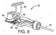
好ましくは、作動部材22は、カテーテルの近位端部で機械的ハンドル32で操縦される。例えば、レバー34はラック38と係合するピニオン部分36を有する。レバー34を押し下げるとピニオン36がラック38に沿って移動し、したがって、押込部材40を遠位方向に動かす。レバー34の作動がストラット20を屈折するように構成された軸運動に変換されるように、押込部材40は作動部材22に作動的に接続される。ラチェット42は、押込部材40と係合するように構成され、解除されるまで所望位置で押込部材を保持する。以下で理解されるように、ハンドル32の機械的な性質は、作動部材22を介してストラット20に伝えられる力の量に関して操作者に直接触知できるフィードバックを与える。更にこの構成は、ストラット20の屈折によって引き起こされた拡張の量を操作者が段階的に調節を行うことを可能にする。
Preferably, the
図7に示す本発明の別の実施形態は、ノーズコーン54内の遠位端部で終端する細長い管状部材52を有するリエントリカテーテル50を一般に含み、そのリエントリカテーテルは、脈管構造を通り進み易いようにテーパー状の形状を好ましくは有する。外側の管状部材52は、ノーズコーン54に隣接した遠位端部でウィンドウ56を形成する。複数の屈折可能なストラット58は、ウィンドウ56内に長手方向に配置される。ストラット58の遠位端部はノーズコーン54で固定される。ストラット20の近位端部は、作動部材60に作動的に接続され、作動部材60によって軸方向に移動するように構成され、屈折が起こる。この実施形態では、作動部材22は、外側の管状部材52内に同軸状に配置されたハイポチューブを含む。作動部材60は外側の管状部材52に対して軸方向に摺動するように構成される。作動部材60の遠位運動は、ストラット58を外側に曲げ、カテーテル50の遠位端部をウィンドウ56で半径方向に拡張させる。外側の管状部材52上の横方向ポート62はウィンドウ54と対向する。好ましくは、側面ポート62は、作動部材60を横方向に通り進んだガイドワイヤーを向け直すように構成され、その結果、ガイドワイヤーの先端が内膜壁を貫通し血管の真腔にアクセスできる。
Another embodiment of the present invention shown in FIG. 7 generally includes a
次に、本発明の更に別の実施形態を図8及び9に示す。図7に示す実施形態と類似して、カテーテル70は、外側の管状部材74の遠位端部に配置された複数の屈折可能なストラット72を特色とする。ストラット72は、拡張した形状へ屈折されるとき、加えられた力がより均等に配分されるようにより幅広いプロフィールをもたらすように構成される。ストラット72は、ノーズコーン76によって遠位端部で固定される。ストラット72の近位端部は、外側の管状部材74内に摺動可能に配置された細長い管状の作動部材78に固定される。作動部材78のルーメン80を通して前進したガイドワイヤーは、カテーテル70が内膜下領域に位置決めされるとき、側面ポート82を通して血管の腔の方に向くように構成される。必要に応じて、ストラット72は、圧力の配分を増やすためにより幅広いプロフィールを有すことができる。例えば、ストラット72は、拡張したとき、縁部が隣接する又は接触するように形成することができる。そのような実施形態において、ストラット72は弛緩時の拡張していない形態のとき重なり合う。ストラット72は、外側の管状部材74の遠位端部に形成されたウィンドウ84内に配置される。
Next, still another embodiment of the present invention is shown in FIGS. Similar to the embodiment shown in FIG. 7, the
一般に、本発明の要素は、ステンレス鋼等の金属、ポリエチレン等の重合体、及び複合材料を含む従来材から形成することができる。以下で論ずるように、形状記憶ニッケルチタン合金は、ストラット及びリエントリカニューレ用に好適である。 In general, the elements of the present invention can be formed from conventional materials including metals such as stainless steel, polymers such as polyethylene, and composite materials. As discussed below, shape memory nickel titanium alloys are suitable for struts and reentrant cannulas.
図10〜14は、血管94の腔92を完全に閉塞している病変90に対する本発明のリエントリカテーテルの作動の種々な態様を示す。実施形態ではカテーテル10が示されているが、本明細書で論じる例示的な実施形態、又は本発明の特徴を有する他の実施形態のいずれも、同様な方法で使用することができることが認識されよう。図10に示すように、カテーテル10は、内膜層98と外膜層100との間の内膜下領域96を前進している。必要に応じて、ストラット20は、拡張させて内膜層98と外膜層100との間に空間を作り、カテーテル10が前進し易くすることができる。
FIGS. 10-14 illustrate various aspects of the operation of the reentry catheter of the present invention for a
一旦カテーテル10の遠位先端部が病変90を越えて十分な距離に前進すると、作動部材22を遠位方向に軸方向に動かすことで、図11に示すようにストラット20が半径方向外側に屈折する。膜24は、外膜層100に対して加えられる力を配分する。上述のように、ストラット20の拡張はカテーテル10を安定させ、側面ポート26が内膜層98に押当てられる。
Once the distal tip of the
カテーテル10がストラット20の拡張によって支持されると、カニューレ30は、図12に示すように側面ポート26を出て前進することができる。場合によっては、腔92にアクセスするために、内膜層98に加えて病変90の一部分を貫通する必要がある。病変90が石灰化又は硬化している場合、カニューレ30の前進にかなりの抵抗を生じ得る。ストラット20の拡張によって、カテーテル10は外膜層100の幅広い領域と係合することができ、必要な支持を提供するのに役立ち、その結果、カニューレ30は位置合わせ又は配向を失うことなく病変90を押し通ることができる。
When the
図13は、図12の線A−Aで得た断面を示す。見て分かるように、ストラット20の拡張は、移動した外膜層100の幾何学形状内に合うように構成されたプロフィールでカテーテル10を提供する。これは、側面ポート26が腔92と実質的に垂直に位置合わせをするのに役立つ。好ましくは、改善された配向は、任意の視覚化の必要性を最小限にするのに役立つ。更に、ストラット20の拡張によってもたらされた拡大領域は、外膜層100のより大きな部分と係合する。そのような拡張なしでは、硬化した病変の貫通を試みるとき、カテーテルだけのより狭いプロフィールは、比較的弾性のある層の中に押し返される傾向がより大きい。
FIG. 13 shows a cross section taken along line AA in FIG. As can be seen, the expansion of the
図13に示すように、ストラット20及びウィンドウ18は、外側の管状部材12の円周のほぼ120°に相当する。本発明の更なる態様では、ストラット20によって占められる円周の割合は、動作特性を変えるために変更することができる。例えば、別の実施形態では、図14に示すようにストラット20及びウィンドウ18は、外側の管状部材12の円周のほぼ240°に相当する。一般に、ウィンドウ18によって占められる部分は、ほぼ90°〜270°の範囲であり得る。以下で理解されるように、そのような実施形態は、外膜層100の内膜層98からの分離により形成された空間内で、より密接した嵌着を提供することができる。
As shown in FIG. 13, the
本開示の別の態様は、本明細書で開示するカテーテルを使用することで達成できる全体的な径の縮小である。屈折可能なストラットの拡張によって提供された支持の増加により、病変を貫通するとき、抗力に抵抗する能力を維持するために必要な構造剛性が少なくて済む。更に、支持の増加によって、より小径のガイドワイヤー、例えば、0.36cm(0.14インチ)のガイドワイヤーの使用も可能になる。現在好ましい実施形態は、フレンチサイズ6以下のカテーテルを含む。同様に、カテーテルは向上した柔軟性を持つことができ、より広範囲の領域にアクセスすることができる。プッシャビリティーのために高い剛性が必要な場合、上述したように屈折可能なストラットに張力を加えることができる。更なる径の縮小は、リエントリカニューレを特徴としないカテーテル50及び70等の実施形態を用いることで達成することができる。例えば、本発明の一実施形態は、3フレンチの径を有し、腸骨の分岐部を誘導し表在の大腿動脈の位置まで対側アプローチを可能にするのに十分な柔軟性を有する。以下で理解されるように、そのような実施形態は脛骨及び他の膝下領域へのアクセスに使用することができる。小さい径を有する実施形態は、冠状動脈の用途にも好適であり得る。
Another aspect of the present disclosure is the overall diameter reduction that can be achieved using the catheters disclosed herein. The increased support provided by the expansion of the refractive struts requires less structural rigidity to maintain the ability to resist drag when penetrating the lesion. In addition, the increased support also allows the use of smaller diameter guidewires, for example, 0.36 cm (0.14 inch) guidewires. The presently preferred embodiment includes a catheter of French size 6 or less. Similarly, the catheter can have increased flexibility and can access a wider area. When high rigidity is required for pushability, tension can be applied to the deflectable struts as described above. Further diameter reduction can be achieved using embodiments such as
本発明の現在好ましい実施形態では、ストラット20、58又は72は、ニチノール等のニッケルチタン合金から形成される。更に好ましくは、カニューレ30はニッケルチタン合金から形成することができる。当業者に既知のように、これらの合金は、形状記憶及び/又は超弾性の特性を示し得る。一般に、形状記憶は、部材が第2の形状に変形することを可能にし、しかも加熱されると元の形状に戻る。一方で、超弾性の特性は、金属がひずみ及び変形を受けることを一般に可能にし、相変態が生じる。一旦ひずみが取り除かれると、超弾性部材は相を変え元の形状に戻る。これらの相は、比較的低い引張り強度を有し、比較的低温で安定するマルテンサイト相、及び比較的高い引張り強度を有し、マルテンサイト相よりも高い温度で安定するオーステナイト相である。
In the presently preferred embodiment of the present invention, struts 20, 58 or 72 are formed from a nickel titanium alloy such as nitinol. More preferably,
形状記憶特性は、金属を、マルテンサイト相からオーステナイト相への転移が完了する温度以上の温度、すなわち、オーステナイト相が安定する温度(Af温度)以上の温度まで加熱することによって、合金に付与される。この加熱処理中の金属の形状は、「記憶された」形状である。加熱処理された金属は、マルテンサイト相が安定する温度まで冷却され、オーステナイト相をマルテンサイト相に転移させる。次いで、マルテンサイト相内の金属は、例えば、患者の体内へのその進入を促進するように塑性的に変形される。マルテンサイトからオーステナイトへの転移温度以上の温度までの、その後の変形されたマルテンサイト相の加熱は、変形したマルテンサイト相をオーステナイト相へ転移させ、この相転移中に、金属は、未拘束の場合、その本来の形状に戻る。拘束されている場合、金属は、拘束が除去されるまでマルテンサイトのままである。 Shape memory characteristics are imparted to the alloy by heating the metal to a temperature equal to or higher than the temperature at which the transition from the martensite phase to the austenite phase is completed, that is, a temperature equal to or higher than the temperature at which the austenite phase is stabilized (Af temperature). The The shape of the metal during this heat treatment is a “memorized” shape. The heat-treated metal is cooled to a temperature at which the martensite phase is stabilized, and the austenite phase is transferred to the martensite phase. The metal in the martensite phase is then plastically deformed to facilitate its entry into the patient's body, for example. Subsequent heating of the deformed martensite phase to a temperature above the transition temperature from martensite to austenite causes the deformed martensite phase to transition to the austenite phase, during which the metal is unconstrained. If so, it returns to its original shape. If constrained, the metal remains martensite until the restraint is removed.
応力が、オーステナイトが安定する温度(すなわち、マルテンサイト相のオーステナイトへの転移が完了する温度)以上の温度で超弾性特性を呈するニチノール等の金属の試料に適用されるとき、該試料は、次いで、合金がオーステナイト相からマルテンサイト相への応力誘発相転移を受ける特定の応力レベルに達するまで、弾性的に変形する。相転移が進行すると、合金は、有意なひずみの増加を受けるが、応力の対応する増加はほとんど、又は全くない。ひずみが増加する一方、応力は、マルテンサイト相へのオーステナイト相の転移が完了するまで、実質的に一定のままである。その後、更なる変形を引き起こすために更なる応力の増加が必要である。マルテンサイト金属は、まず、付加的な応力の印加時に、弾性的に、次いで、永久的残留変形で塑性的に変形する。 When stress is applied to a sample of a metal such as nitinol that exhibits superelastic properties at a temperature above the temperature at which the austenite stabilizes (ie, the temperature at which the transition of the martensite phase to austenite is complete), the sample is then The alloy deforms elastically until it reaches a specific stress level that undergoes a stress-induced phase transition from the austenite phase to the martensite phase. As the phase transition progresses, the alloy undergoes a significant increase in strain, but there is little or no corresponding increase in stress. While the strain increases, the stress remains substantially constant until the transition of the austenite phase to the martensite phase is complete. Thereafter, further stress increases are required to cause further deformation. Martensitic metal first deforms elastically upon application of additional stress and then plastically with permanent residual deformation.
任意の永久的変形が生じる前に試料上の荷重が除去される場合、マルテンサイト試料は、弾性的に回復し、オーステナイト相に逆転移する。応力減少は、まず、ひずみの低下を引き起こす。応力減少が、マルテンサイト相がオーステナイト相に逆転移するレベルに到達すると、試料内の応力レベルは、オーステナイト相への逆転移が完了する、すなわち、対応するごくわずかな応力減少でひずみの有意な回復が存在するまで、本質的に一定のままである(しかし、実質的に、オーステナイトがマルテンサイトに転移する一定の応力レベル以下)。オーステナイトへの逆転移が完了した後、更なる応力減少は、弾性のひずみの減少を引き起こす。荷重の印加時に比較的一定応力で有意なひずみをもたらし、かつ荷重の除去時の変形から回復するこの能力は、一般に、超弾性又は擬似弾性と称される。 If the load on the sample is removed before any permanent deformation occurs, the martensitic sample recovers elastically and reversely transitions to the austenite phase. Stress reduction first causes strain reduction. When the stress reduction reaches a level at which the martensite phase reverses into the austenite phase, the stress level in the sample completes the reverse transition to the austenite phase, i.e., the corresponding negligible stress reduction causes a significant amount of strain. It remains essentially constant until recovery exists (but substantially below a certain stress level at which austenite transitions to martensite). After the reverse transition to austenite is complete, further stress reduction causes a reduction in elastic strain. This ability to cause significant strain at a relatively constant stress when a load is applied and to recover from deformation upon removal of the load is commonly referred to as superelastic or pseudoelastic.
上述の特性は、ストラット20、58及び72が弛緩時の拡張していない状態から曲がり出て拡張した形状に屈折するのに特に好適であることを当業者は理解するであろう。同様に、カニューレ30は、作動される前に直線の形状に拘束されることができ、横方向ポート26を出て前進する際に、真腔をより直接ねらうために湾曲したプロフィールをとることができる。
One skilled in the art will appreciate that the above-described characteristics are particularly well suited for the
状況によっては(It some situations)、血管の真腔に戻る通路が形成されるように完全閉塞に対して本発明の機器の位置を判定する必要がある場合がある。最も簡単に、そのような位置の判定は、従来の方法で血管を透視撮影することで行うことができる。そのような透視撮影の代わりに又は追加として、血管内画像化、例えば、血管内超音波撮影(IVUS)、及び様々な光学画像モダリティー(optical imaging modelities)、例えば、光干渉断層撮影(OCT)が用いられてもよい。例えば、最初内膜下領域にアクセスするために超音波画像ガイドワイヤーが使用されてもよく、及び/又は、内膜下領域にアクセスするために使用されるワイヤーと交換されてもよい。内膜下領域中にある画像ガイドワイヤーは、血管腔内で閉塞物質の有無を容易に検出し得る。閉塞物質から閉塞物質無しまでの移行が検出されると、ガイドワイヤーの位置が完全閉塞を越えて前進したことが分かる。 In some situations, it may be necessary to determine the position of the device of the present invention relative to total occlusion so that a passage back to the true lumen of the blood vessel is formed. Most simply, such a position can be determined by fluoroscopic imaging of the blood vessel using a conventional method. As an alternative or in addition to such fluoroscopy, intravascular imaging, such as intravascular ultrasound (IVUS), and various optical imaging models, such as optical coherence tomography (OCT) May be used. For example, an ultrasound image guidewire may be used initially to access the subintimal region and / or may be replaced with a wire used to access the subintimal region. An image guidewire in the subintimal region can easily detect the presence or absence of an occlusive substance within the vessel lumen. When a transition from occlusive material to no occlusive material is detected, it can be seen that the position of the guide wire has advanced beyond the complete occlusion.
本明細書に図示及び説明した実施形態は、最も実用的かつ好ましい実施形態であると考えられるが、当業者であれば、本明細書に説明及び図示した特定の設計及び方法からの変更はそれ自体当業者にとって自明であり、本発明の趣旨及び範囲から逸脱することなく使用できることは明らかであろう。本発明は、説明及び図示される特定の構造に限定されるものではないが、付属の特許請求の範囲に含まれ得るすべての改変例と一貫性を有するものとして解釈されなければならない。 While the embodiments illustrated and described herein are considered to be the most practical and preferred embodiments, those skilled in the art will appreciate modifications from the specific designs and methods described and illustrated herein. It will be apparent to those skilled in the art that it can be used without departing from the spirit and scope of the invention. The present invention is not limited to the specific structures described and illustrated, but should be construed as consistent with all modifications that may be included within the scope of the appended claims.
〔実施の態様〕
(1) 内膜下領域から血管の腔までの通路の形成を容易にするリエントリカテーテルであって、遠位端部及び前記遠位端部に隣接したウィンドウを有する細長い外側の管状部材と、前記ウィンドウ内に長手方向に配置された複数の屈折可能なストラットと、前記外側の管状部材内に同軸状に配置された作動部材と、を含み、前記外側の管状部材に対する前記作動部材の軸運動が前記ストラットを半径方向外側に屈折させるように、前記屈折可能なストラットの近位端部が前記作動部材の遠位端部に作動的に接続される、リエントリカテーテル。
(2) 前記外側の管状部材に前記ウィンドウと対向する位置で側面ポートを更に含む、実施態様1に記載のリエントリカテーテル。
(3) 前記ストラットはニッケルチタン合金から形成される、実施態様1に記載のリエントリカテーテル。
(4) 前記外側の管状部材は円周を有し、前記ウィンドウはほぼ120°〜240°の範囲に相当する前記円周の部分を占める、実施態様1に記載のリエントリカテーテル。
(5) 前記作動部材に加えられた張力は前記細長い管状部材の前記遠位端部で剛性を高くする、実施態様1に記載のリエントリカテーテル。
Embodiment
(1) a re-entry catheter that facilitates the formation of a passage from a subintimal region to a blood vessel lumen, an elongated outer tubular member having a distal end and a window adjacent to the distal end; A plurality of deflectable struts disposed longitudinally within the window; and an actuating member disposed coaxially within the outer tubular member, the axial movement of the actuating member relative to the outer tubular member A re-entry catheter wherein a proximal end of the refractable strut is operatively connected to a distal end of the actuating member such that refracts the strut radially outward.
(2) The reentry catheter according to embodiment 1, further comprising a side port at a position facing the window on the outer tubular member.
(3) The reentry catheter according to embodiment 1, wherein the strut is formed of a nickel titanium alloy.
(4) The reentry catheter according to embodiment 1, wherein the outer tubular member has a circumference, and the window occupies a portion of the circumference corresponding to a range of approximately 120 ° to 240 °.
(5) The reentry catheter according to embodiment 1, wherein the tension applied to the actuating member increases rigidity at the distal end of the elongated tubular member.
(6) 前記ストラットによって支持され前記ストラット間で力を配分するように構成された膜を更に含む、実施態様1に記載のリエントリカテーテル。
(7) 前記作動部材内に同軸状に配置された切断部材を更に含む、実施態様2に記載のリエントリカテーテル。
(8) 前記切断部材は前記側面ポートから出て前進するように構成されたカニューレを含む、実施態様7に記載のリエントリカテーテル。
(9) 前記切断部材はニッケルチタン合金から形成される、実施態様8に記載のリエントリカテーテル。
(10) 前記作動部材は、前記作動部材を段階的な量で軸方向に遠位に動かすように構成された機械的ハンドルに作動的に接続される、実施態様1に記載のリエントリカテーテル。
6. The reentry catheter according to embodiment 1, further comprising a membrane supported by the struts and configured to distribute forces between the struts.
(7) The reentry catheter according to
8. The reentry catheter according to embodiment 7, wherein the cutting member includes a cannula configured to advance out of the side port.
(9) The reentry catheter according to embodiment 8, wherein the cutting member is formed of a nickel titanium alloy.
The reentry catheter according to embodiment 1, wherein the actuating member is operatively connected to a mechanical handle configured to move the actuating member axially distally in a stepped amount.
(11) 前記カテーテルはほぼ2mm(ほぼ6フレンチ)以下の範囲の径を有する、実施態様1に記載のリエントリカテーテル。
(12) 内膜下領域から血管の腔まで通路を形成する方法であって、
a)遠位端部及び前記遠位端部に隣接したウィンドウを有する細長い外側の管状部材と、前記ウィンドウ内に長手方向に配置された複数の屈折可能なストラットと、前記外側の管状部材内に同軸状に配置された作動部材であって、前記屈折可能なストラットの近位端部が前記作動部材の遠位端部に作動的に接続される、作動部材と、前記ウィンドウに対向して位置する側面ポートと、を備えたリエントリカテーテルを提供するステップと、
b)前記カテーテルの前記遠位端部を内膜下領域を通って前進させるステップと、
c)前記作動部材を遠位方向に動かして前記ストラットを半径方向外側に屈折させるステップと、
d)リエントリ機器を前記側面ポートを通して前進させ前記血管の内膜層を通って前記腔内に前進させるステップと、を含む方法。
(13) 前記作動部材を遠位方向に動かして前記ストラットを半径方向外側に屈折させる前記ステップは、前記血管の外膜層と係合させ前記側面ポートを前記内膜層に押しつけて位置決めさせる、実施態様12に記載の方法。
(14) 機器を前記側面ポートを通して前進させるステップはガイドワイヤーを前進させることを含む、実施態様12に記載の方法。
(15) リエントリカテーテルを提供するステップは、前記作動部材内に同軸状に配置されたカニューレを含むリエントリ機器を備えた前記カテーテルを提供することを更に含み、前記側面ポートを通してリエントリ機器を前進させるステップは、前記作動部材を通して前記カニューレを摺動させることを含む、実施態様12に記載の方法。
(11) The reentry catheter according to embodiment 1, wherein the catheter has a diameter in a range of approximately 2 mm (approximately 6 French) or less.
(12) A method of forming a passage from a subintimal region to a blood vessel cavity,
a) an elongated outer tubular member having a distal end and a window adjacent to the distal end; a plurality of refractable struts disposed longitudinally within the window; and within the outer tubular member Coaxially arranged actuating member, wherein the proximal end of the deflectable strut is operatively connected to the distal end of the actuating member and positioned opposite the window Providing a re-entry catheter with a side port;
b) advancing the distal end of the catheter through the subintimal region;
c) moving the actuating member distally to refract the struts radially outward;
d) advancing a reentry device through the side port and advancing through the intimal layer of the blood vessel into the cavity.
(13) The step of moving the actuating member in the distal direction to refract the strut radially outwardly engages the outer membrane layer of the blood vessel and presses the side port against the intima layer to position it. Embodiment 13. The method according to
14. The method of
(15) Providing a reentry catheter further comprises providing the catheter with a reentry device comprising a cannula coaxially disposed within the actuating member, wherein the reentry device is passed through the side port. 13. The method of
(16) 前記作動部材に張力を加えることによって前記カテーテルの前記遠位端部に剛性を与えるステップと、前記カテーテルの前記遠位端部が脈管構造を通り前記内膜下領域に達するのを誘導するステップとを更に含む、実施態様12に記載の方法。
(17) リエントリカテーテルを提供するステップは、前記作動部材に作動的に接続された機械的ハンドルを備えた前記カテーテルを提供することを更に含み、前記ハンドルを作動して前記作動部材を段階的な量で軸方向に遠位に動かすステップを更に含む、実施態様12に記載の方法。
(18) 前記ストラットを半径方向外側に屈折させ前記内膜層と外膜層との間に空間を作るために前記作動部材を遠位方向に動かすステップと、前記カテーテルの前記遠位先端部を前記空間の中に前進させるステップとを更に含む、実施態様12に記載の方法。
(19) 前記内膜下領域は前記血管を閉塞する病変に隣接し、前記側面ポートを通してリエントリ機器を前進させるステップは前記病変の少なくとも一部分を貫通することを更に含む、実施態様12に記載の方法。
(16) stiffening the distal end of the catheter by applying tension to the actuating member; and allowing the distal end of the catheter to reach the subintimal region through the vasculature. 13. The method of
(17) Providing a re-entry catheter further comprises providing the catheter with a mechanical handle operatively connected to the actuating member, and actuating the handle to step the actuating member. 13. The method of
(18) moving the actuating member in a distal direction to refract the strut radially outward to create a space between the inner membrane layer and the outer membrane layer; and the distal tip of the catheter 13. The method of
19. The embodiment of
Claims (7)
前記切断部材は、前記側面ポートから出て前進するように構成されるカニューレを含み、
前記リエントリカテーテルは2mm(6フレンチ)以下の範囲の径を有する、
リエントリカテーテル。 A reentry catheter that is used in a subintimal region that is a region between an intima layer and an outer membrane layer in a blood vessel, and that facilitates formation of a passage from the subintimal region to a blood vessel cavity. An elongate outer tubular member having a distal end and a window adjacent to the distal end; a plurality of refractable struts disposed longitudinally within the window; and coaxial within the outer tubular member An actuating member arranged in a shape, a side port at a position facing the window of the outer tubular member, and a cutting member arranged coaxially within the actuating member, and with respect to the outer tubular member The proximal end of the deflectable strut is operatively connected to the distal end of the actuating member such that axial movement of the actuating member refracts the strut radially outward;
Said cutting member, viewed contains a cannula configured to be advanced out of the side ports,
The re-entry catheter has a diameter in the range of 2 mm (6 French) or less ,
Reentry catheter.
Applications Claiming Priority (5)
| Application Number | Priority Date | Filing Date | Title |
|---|---|---|---|
| US201161502684P | 2011-06-29 | 2011-06-29 | |
| US61/502,684 | 2011-06-29 | ||
| US13/232,115 | 2011-09-14 | ||
| US13/232,115 US8920449B2 (en) | 2011-06-29 | 2011-09-14 | System and method for re-entering a vessel lumen |
| PCT/US2012/043542 WO2013003194A1 (en) | 2011-06-29 | 2012-06-21 | System for re-entering a vessel lumen |
Related Child Applications (1)
| Application Number | Title | Priority Date | Filing Date |
|---|---|---|---|
| JP2017082779A Division JP6573645B2 (en) | 2011-06-29 | 2017-04-19 | Reentry catheter |
Publications (2)
| Publication Number | Publication Date |
|---|---|
| JP2014520597A JP2014520597A (en) | 2014-08-25 |
| JP6346858B2 true JP6346858B2 (en) | 2018-06-20 |
Family
ID=47389453
Family Applications (4)
| Application Number | Title | Priority Date | Filing Date |
|---|---|---|---|
| JP2014518663A Expired - Fee Related JP6346858B2 (en) | 2011-06-29 | 2012-06-21 | System and method for re-entering a blood vessel cavity |
| JP2017082779A Active JP6573645B2 (en) | 2011-06-29 | 2017-04-19 | Reentry catheter |
| JP2019078832A Active JP7116005B2 (en) | 2011-06-29 | 2019-04-17 | reentry catheter |
| JP2021083217A Pending JP2021151487A (en) | 2011-06-29 | 2021-05-17 | System for re-entering vessel lumen |
Family Applications After (3)
| Application Number | Title | Priority Date | Filing Date |
|---|---|---|---|
| JP2017082779A Active JP6573645B2 (en) | 2011-06-29 | 2017-04-19 | Reentry catheter |
| JP2019078832A Active JP7116005B2 (en) | 2011-06-29 | 2019-04-17 | reentry catheter |
| JP2021083217A Pending JP2021151487A (en) | 2011-06-29 | 2021-05-17 | System for re-entering vessel lumen |
Country Status (7)
| Country | Link |
|---|---|
| US (3) | US8920449B2 (en) |
| EP (2) | EP2726137B1 (en) |
| JP (4) | JP6346858B2 (en) |
| CN (2) | CN106902441B (en) |
| AU (6) | AU2012275757A1 (en) |
| CA (1) | CA2840200C (en) |
| WO (1) | WO2013003194A1 (en) |
Families Citing this family (32)
| Publication number | Priority date | Publication date | Assignee | Title |
|---|---|---|---|---|
| US9511214B2 (en) | 2006-05-02 | 2016-12-06 | Vascular Access Technologies, Inc. | Methods of transvascular retrograde access placement and devices for facilitating therein |
| US9623217B2 (en) | 2012-05-30 | 2017-04-18 | Vascular Access Techonlogies, Inc. | Transvascular access methods |
| WO2013181397A1 (en) | 2012-05-30 | 2013-12-05 | Vascular Access Technologies, Inc. | Transvascular access device and method |
| US9669197B2 (en) * | 2012-11-15 | 2017-06-06 | Boston Scientific Scimed, Inc. | Expandable member dissection port and related methods |
| US9451984B2 (en) | 2013-01-15 | 2016-09-27 | Boston Scientific Scimed, Inc. | Subintimal re-entry catheter with actuatable orientation mechanism |
| US9878128B2 (en) | 2013-03-14 | 2018-01-30 | Boston Scientific Scimed, Inc. | Systems, apparatus and methods for treating blood vessels |
| JP6182660B2 (en) * | 2013-03-14 | 2017-08-16 | ボストン サイエンティフィック サイムド,インコーポレイテッドBoston Scientific Scimed,Inc. | Subintimal reentry catheter with shape-controlled balloon |
| US9301777B2 (en) | 2013-07-29 | 2016-04-05 | Invatec S.P.A. | Occlusion bypassing apparatuses and methods for bypassing an occlusion in a blood vessel |
| US9308356B2 (en) | 2013-07-29 | 2016-04-12 | Invatec S.P.A. | Occlusion bypassing apparatuses and methods for bypassing an occlusion in a blood vessel |
| DE102013216030A1 (en) * | 2013-08-13 | 2015-02-19 | Olympus Winter & Ibe Gmbh | Guide catheter with stabilization mechanism and method for inserting a guide catheter |
| US9364642B2 (en) | 2013-08-14 | 2016-06-14 | Invatec S.P.A. | Balloon catheter systems and methods for bypassing an occlusion in a blood vessel |
| US9320874B2 (en) | 2013-08-15 | 2016-04-26 | Invatec S.P.A. | Catheter systems with a blocking mechanism and methods for bypassing an occlusion in a blood vessel |
| US9446222B2 (en) | 2014-03-05 | 2016-09-20 | Invatec S.P.A. | Catheter assemblies and methods for stabilizing a catheter assembly within a subintimal space |
| US10098650B2 (en) | 2014-06-09 | 2018-10-16 | Boston Scientific Scimed, Inc. | Systems and methods for treating atherosclerotic plaque |
| US10391282B2 (en) | 2014-07-08 | 2019-08-27 | Teleflex Innovations S.À.R.L. | Guidewires and methods for percutaneous occlusion crossing |
| US10525260B2 (en) | 2014-08-06 | 2020-01-07 | NeuroTronik IP Holding (Jersey) Limited | Electrodes and electrode positioning systems for transvascular neuromodulation |
| US10456557B2 (en) | 2014-08-14 | 2019-10-29 | Invatec S.P.A. | Occlusion bypassing apparatus with varying flexibility and methods for bypassing an occlusion in a blood vessel |
| US10130384B2 (en) * | 2014-09-23 | 2018-11-20 | CARDINAL HEALTH SWITZERLAND 515 GmbH | Catheter systems and methods for re-entry in body vessels with chronic total occlusion |
| EP3270999B1 (en) | 2015-03-19 | 2022-12-07 | Boston Scientific Scimed, Inc. | Subintimal re-entry balloon catheter and method of forming thereof |
| US10172632B2 (en) | 2015-09-22 | 2019-01-08 | Medtronic Vascular, Inc. | Occlusion bypassing apparatus with a re-entry needle and a stabilization tube |
| US10327791B2 (en) | 2015-10-07 | 2019-06-25 | Medtronic Vascular, Inc. | Occlusion bypassing apparatus with a re-entry needle and a distal stabilization balloon |
| CA3023251A1 (en) * | 2016-05-03 | 2017-11-09 | Access Flow Systems, Llc | Vascular access devices and methods |
| US10617854B2 (en) | 2016-12-09 | 2020-04-14 | Vascular Access Technologies, Inc. | Trans-jugular carotid artery access methods |
| CN106691385A (en) * | 2016-12-29 | 2017-05-24 | 天津恒宇医疗科技有限公司 | Support frame OCT imaging duct |
| US11654224B2 (en) | 2016-12-30 | 2023-05-23 | Vascular Access Technologies, Inc. | Methods and devices for percutaneous implantation of arterio-venous grafts |
| US11083490B2 (en) * | 2017-09-21 | 2021-08-10 | Covidien Lp | Systems and methods for large tissue specimen removal |
| WO2019083757A1 (en) | 2017-10-26 | 2019-05-02 | Teleflex Innovations S.A.R.L. | Subintimal catheter device and assembly |
| CN110279931B (en) * | 2018-03-15 | 2021-12-28 | 王恩长 | Multifunctional balloon catheter and system |
| CN109045439B (en) * | 2018-08-21 | 2020-08-14 | 业聚医疗器械(深圳)有限公司 | Catheter system |
| US11369392B2 (en) | 2019-04-05 | 2022-06-28 | Traverse Vascular, Inc. | Intravascular catheter with fluoroscopically visible indicium of rotational orientation |
| US20200360666A1 (en) * | 2019-05-13 | 2020-11-19 | Medtronic Vascular, Inc. | Guide catheter with support wires |
| CN115363821A (en) * | 2021-05-21 | 2022-11-22 | 爱德华兹生命科学公司 | Securing a guidewire delivery catheter in a coronary sinus using a mechanical release arm |
Family Cites Families (24)
| Publication number | Priority date | Publication date | Assignee | Title |
|---|---|---|---|---|
| JPH0352495Y2 (en) * | 1986-11-29 | 1991-11-14 | ||
| DE59010156D1 (en) | 1989-06-01 | 1996-04-04 | Schneider Europ Ag | Catheter arrangement with a guide wire and method for producing such a guide wire |
| US5707362A (en) * | 1992-04-15 | 1998-01-13 | Yoon; Inbae | Penetrating instrument having an expandable anchoring portion for triggering protrusion of a safety member and/or retraction of a penetrating member |
| US6726677B1 (en) * | 1995-10-13 | 2004-04-27 | Transvascular, Inc. | Stabilized tissue penetrating catheters |
| IL124037A (en) * | 1995-10-13 | 2003-01-12 | Transvascular Inc | Device and system for interstitial transvascular intervention |
| US6440088B1 (en) * | 1996-05-24 | 2002-08-27 | Precision Vascular Systems, Inc. | Hybrid catheter guide wire apparatus and method |
| US6027514A (en) | 1997-12-17 | 2000-02-22 | Fox Hollow Technologies, Inc. | Apparatus and method for removing occluding material from body lumens |
| JP4656690B2 (en) * | 2000-04-27 | 2011-03-23 | 川澄化学工業株式会社 | Vascular drug delivery catheter |
| AU2002235159A1 (en) | 2000-12-05 | 2002-06-18 | Lumend, Inc. | Catheter system for vascular re-entry from a sub-intimal space |
| US20020072706A1 (en) * | 2000-12-11 | 2002-06-13 | Thomas Hiblar | Transluminal drug delivery catheter |
| US6663577B2 (en) | 2001-12-07 | 2003-12-16 | Abbott Laboratories | Catheter deployment device |
| JP4731471B2 (en) | 2003-04-16 | 2011-07-27 | ジェネシス・テクノロジーズ・エルエルシー | Medical devices and methods |
| US7922687B2 (en) | 2003-11-17 | 2011-04-12 | Cook Medical Technologies Llc | Catheter with centering wire |
| US20060004323A1 (en) | 2004-04-21 | 2006-01-05 | Exploramed Nc1, Inc. | Apparatus and methods for dilating and modifying ostia of paranasal sinuses and other intranasal or paranasal structures |
| CA2602662A1 (en) * | 2005-03-30 | 2006-10-05 | Lumend, Inc. | Catheter systems for crossing total occlusions in vasculature |
| US8083727B2 (en) | 2005-09-12 | 2011-12-27 | Bridgepoint Medical, Inc. | Endovascular devices and methods for exploiting intramural space |
| US9119651B2 (en) * | 2006-02-13 | 2015-09-01 | Retro Vascular, Inc. | Recanalizing occluded vessels using controlled antegrade and retrograde tracking |
| WO2007122908A1 (en) * | 2006-03-29 | 2007-11-01 | Terumo Kabushiki Kaisha | Medical instrument |
| US10888354B2 (en) | 2006-11-21 | 2021-01-12 | Bridgepoint Medical, Inc. | Endovascular devices and methods for exploiting intramural space |
| WO2008120209A1 (en) | 2007-03-29 | 2008-10-09 | Dan Rottenberg | Lumen reentry devices and methods |
| GB0713497D0 (en) | 2007-07-11 | 2007-08-22 | Angiomed Ag | Device for catheter sheath retraction |
| US8075519B2 (en) * | 2007-12-06 | 2011-12-13 | Abbott Cardiovascular Systems Inc. | Agent delivery catheter having a radially expandable centering support members |
| US20090230167A1 (en) | 2008-03-17 | 2009-09-17 | Medtronic Vascular, Inc. | Endostapler Biasing Mechanism |
| JP5142785B2 (en) * | 2008-03-27 | 2013-02-13 | テルモ株式会社 | Pin driving device |
-
2011
- 2011-09-14 US US13/232,115 patent/US8920449B2/en active Active
-
2012
- 2012-06-21 WO PCT/US2012/043542 patent/WO2013003194A1/en active Application Filing
- 2012-06-21 CN CN201710223404.0A patent/CN106902441B/en active Active
- 2012-06-21 EP EP12733322.7A patent/EP2726137B1/en active Active
- 2012-06-21 JP JP2014518663A patent/JP6346858B2/en not_active Expired - Fee Related
- 2012-06-21 CA CA2840200A patent/CA2840200C/en active Active
- 2012-06-21 EP EP21161632.1A patent/EP3915628A1/en active Pending
- 2012-06-21 CN CN201280031996.1A patent/CN103796705B/en active Active
- 2012-06-21 AU AU2012275757A patent/AU2012275757A1/en not_active Abandoned
-
2014
- 2014-12-23 US US14/580,397 patent/US20150112374A1/en not_active Abandoned
-
2016
- 2016-04-01 US US15/089,205 patent/US10335174B2/en active Active
-
2017
- 2017-04-12 AU AU2017202442A patent/AU2017202442B2/en not_active Ceased
- 2017-04-19 JP JP2017082779A patent/JP6573645B2/en active Active
-
2019
- 2019-01-23 AU AU2019200461A patent/AU2019200461B2/en not_active Ceased
- 2019-04-17 JP JP2019078832A patent/JP7116005B2/en active Active
-
2020
- 2020-01-31 AU AU2020200739A patent/AU2020200739A1/en not_active Abandoned
-
2021
- 2021-05-17 JP JP2021083217A patent/JP2021151487A/en active Pending
- 2021-10-12 AU AU2021250872A patent/AU2021250872A1/en not_active Abandoned
-
2023
- 2023-10-20 AU AU2023251556A patent/AU2023251556A1/en active Pending
Also Published As
| Publication number | Publication date |
|---|---|
| AU2020200739A1 (en) | 2020-02-20 |
| US8920449B2 (en) | 2014-12-30 |
| AU2017202442B2 (en) | 2018-10-25 |
| CN103796705B (en) | 2017-05-03 |
| WO2013003194A1 (en) | 2013-01-03 |
| JP6573645B2 (en) | 2019-09-11 |
| JP2017164513A (en) | 2017-09-21 |
| JP2021151487A (en) | 2021-09-30 |
| AU2019200461B2 (en) | 2019-10-31 |
| CA2840200A1 (en) | 2013-01-03 |
| EP3915628A1 (en) | 2021-12-01 |
| JP7116005B2 (en) | 2022-08-09 |
| US20150112374A1 (en) | 2015-04-23 |
| AU2019200461A1 (en) | 2019-02-07 |
| EP2726137B1 (en) | 2021-03-10 |
| AU2017202442A1 (en) | 2017-05-04 |
| CA2840200C (en) | 2020-06-02 |
| JP2014520597A (en) | 2014-08-25 |
| US20160213386A1 (en) | 2016-07-28 |
| CN106902441B (en) | 2020-03-13 |
| AU2021250872A1 (en) | 2021-11-04 |
| JP2019150595A (en) | 2019-09-12 |
| AU2023251556A1 (en) | 2023-12-21 |
| CN103796705A (en) | 2014-05-14 |
| US20130006282A1 (en) | 2013-01-03 |
| CN106902441A (en) | 2017-06-30 |
| EP2726137A1 (en) | 2014-05-07 |
| AU2012275757A1 (en) | 2014-01-16 |
| US10335174B2 (en) | 2019-07-02 |
Similar Documents
| Publication | Publication Date | Title |
|---|---|---|
| JP6573645B2 (en) | Reentry catheter | |
| JP6013471B2 (en) | System and method for expanding a guiding device to adjust flexibility | |
| US20170143355A1 (en) | Path Creation Through Occlusion | |
| JP6820611B2 (en) | Double concentric guide wire |
Legal Events
| Date | Code | Title | Description |
|---|---|---|---|
| A621 | Written request for application examination |
Free format text: JAPANESE INTERMEDIATE CODE: A621 Effective date: 20150511 |
|
| A977 | Report on retrieval |
Free format text: JAPANESE INTERMEDIATE CODE: A971007 Effective date: 20160323 |
|
| A131 | Notification of reasons for refusal |
Free format text: JAPANESE INTERMEDIATE CODE: A131 Effective date: 20160419 |
|
| A521 | Request for written amendment filed |
Free format text: JAPANESE INTERMEDIATE CODE: A523 Effective date: 20160714 |
|
| A02 | Decision of refusal |
Free format text: JAPANESE INTERMEDIATE CODE: A02 Effective date: 20161220 |
|
| A521 | Request for written amendment filed |
Free format text: JAPANESE INTERMEDIATE CODE: A523 Effective date: 20170419 |
|
| A911 | Transfer to examiner for re-examination before appeal (zenchi) |
Free format text: JAPANESE INTERMEDIATE CODE: A911 Effective date: 20170427 |
|
| A912 | Re-examination (zenchi) completed and case transferred to appeal board |
Free format text: JAPANESE INTERMEDIATE CODE: A912 Effective date: 20170609 |
|
| RD03 | Notification of appointment of power of attorney |
Free format text: JAPANESE INTERMEDIATE CODE: A7423 Effective date: 20170616 |
|
| A711 | Notification of change in applicant |
Free format text: JAPANESE INTERMEDIATE CODE: A711 Effective date: 20170621 |
|
| RD04 | Notification of resignation of power of attorney |
Free format text: JAPANESE INTERMEDIATE CODE: A7424 Effective date: 20170628 |
|
| A61 | First payment of annual fees (during grant procedure) |
Free format text: JAPANESE INTERMEDIATE CODE: A61 Effective date: 20180528 |
|
| R150 | Certificate of patent or registration of utility model |
Ref document number: 6346858 Country of ref document: JP Free format text: JAPANESE INTERMEDIATE CODE: R150 |
|
| R250 | Receipt of annual fees |
Free format text: JAPANESE INTERMEDIATE CODE: R250 |
|
| R250 | Receipt of annual fees |
Free format text: JAPANESE INTERMEDIATE CODE: R250 |
|
| LAPS | Cancellation because of no payment of annual fees |