JP6346238B2 - Suspension stand for temporary scaffolding - Google Patents
Suspension stand for temporary scaffolding Download PDFInfo
- Publication number
- JP6346238B2 JP6346238B2 JP2016208810A JP2016208810A JP6346238B2 JP 6346238 B2 JP6346238 B2 JP 6346238B2 JP 2016208810 A JP2016208810 A JP 2016208810A JP 2016208810 A JP2016208810 A JP 2016208810A JP 6346238 B2 JP6346238 B2 JP 6346238B2
- Authority
- JP
- Japan
- Prior art keywords
- temporary
- seismic isolation
- jump
- spring
- scaffold
- Prior art date
- Legal status (The legal status is an assumption and is not a legal conclusion. Google has not performed a legal analysis and makes no representation as to the accuracy of the status listed.)
- Active
Links
- 239000000725 suspension Substances 0.000 title 1
- 229910000831 Steel Inorganic materials 0.000 claims description 83
- 239000010959 steel Substances 0.000 claims description 83
- 238000002955 isolation Methods 0.000 claims description 71
- 239000000463 material Substances 0.000 claims description 35
- XEEYBQQBJWHFJM-UHFFFAOYSA-N Iron Chemical compound [Fe] XEEYBQQBJWHFJM-UHFFFAOYSA-N 0.000 claims description 22
- 239000000853 adhesive Substances 0.000 claims description 19
- 230000001070 adhesive effect Effects 0.000 claims description 19
- 229910000746 Structural steel Inorganic materials 0.000 claims description 14
- 229910052742 iron Inorganic materials 0.000 claims description 11
- 238000000034 method Methods 0.000 claims description 8
- 230000009191 jumping Effects 0.000 description 34
- 238000010586 diagram Methods 0.000 description 16
- 230000000694 effects Effects 0.000 description 2
- 238000005192 partition Methods 0.000 description 2
- 238000003466 welding Methods 0.000 description 2
- 239000002775 capsule Substances 0.000 description 1
- 238000006243 chemical reaction Methods 0.000 description 1
- 239000002184 metal Substances 0.000 description 1
- 229910052751 metal Inorganic materials 0.000 description 1
- 230000003014 reinforcing effect Effects 0.000 description 1
- 239000000126 substance Substances 0.000 description 1
Images


Landscapes
- Conveying And Assembling Of Building Elements In Situ (AREA)
- Buildings Adapted To Withstand Abnormal External Influences (AREA)
Description
本発明は、仮設足場用跳ね出し架台に関する。特に、ビル又はマンションなどの免震構造建物の免震スラブ内に設置でき、免震構造建物の外壁から水平方向に突出したベランダなどの跳ね出しに沿って、高さ方向に設置した仮設足場が地震などで転倒しないように、仮設足場を支持する仮設足場用跳ね出し架台の構造に関する。 The present invention relates to a temporary scaffolding stand. In particular, there is a temporary scaffolding that can be installed in a seismic isolation slab of a seismic isolation building such as a building or an apartment, and is installed in the height direction along the protruding veranda etc. that protrudes horizontally from the outer wall of the seismic isolation structure building. The present invention relates to a structure of a temporary scaffolding stand for supporting a temporary scaffold so as not to fall down due to an earthquake or the like.
一般に、仮設足場は、建物の外壁面に沿って建物の外部に仮設し、複数の鋼管及び足場部材を組み合わせて階層的に構成している。例えば、枠組足場は、対向させた建枠の両側垂直面を交差筋交いで結合して枠組を補強すると共に、建枠を上方へ必要な高さだけ順次継ぎ足すことによって構築している。 Generally, a temporary scaffold is temporarily constructed along the outer wall surface of a building and is constructed hierarchically by combining a plurality of steel pipes and scaffold members. For example, the frame scaffolding is constructed by reinforcing the frame by connecting the vertical surfaces on opposite sides of the building frame facing each other with crossing bars, and by sequentially adding the building frame upward to the required height.
免震構造建物の外部に仮設足場を設置する場合、従来では、非免震構造の建物を構築する場合と同様に、地面に敷いたコンクリートパネルからなる敷板上に仮設足場を組み立てている。そして、組み立てた仮設足場を壁つなぎ金具によって、免震構造建物の外壁に連結している。 When a temporary scaffold is installed outside a base-isolated structure, conventionally, the temporary scaffold is assembled on a floor plate made of a concrete panel laid on the ground, as in the case of constructing a non-base-isolated structure. The assembled temporary scaffold is connected to the outer wall of the seismically isolated building by a wall-connecting bracket.
しかし、地震などが発生した場合には、免震構造建物の揺れ方向と地面の揺れ方向とは互いに反対方向となるため、免震構造建物の外部に設置した仮設足場は、壁つなぎ金具によって免震構造建物に固定した上部と地面に近い下端部とでは、揺れ方が異なってしまい、仮設足場が転倒する心配があった。 However, in the event of an earthquake, the direction of shaking of the seismic isolation structure and the direction of ground motion are opposite to each other. The upper part fixed to the seismic structure building and the lower end close to the ground had different ways of shaking, and there was a concern that the temporary scaffold would fall.
上記の不具合に対して、免震構造建物に連結した仮設足場が地震などの揺れで転倒することがないように仮設足場を支持する、免震構造建物用枠組足場の支持構造体が開示されている(例えば、特許文献1参照)。 In response to the above problems, a support structure for a frame scaffold for a seismic isolation structure is disclosed that supports the temporary scaffold so that the temporary scaffold connected to the seismic isolation structure does not fall down due to a shake such as an earthquake. (For example, refer to Patent Document 1).
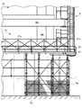
図12は、従来技術による免震構造建物用枠組足場の支持構造体の構成を示す縦断面図である。なお、本願の図12は、特許文献1の図1に相当している。 FIG. 12: is a longitudinal cross-sectional view which shows the structure of the support structure of the frame isolation scaffold for a base isolation structure building by a prior art. Note that FIG. 12 of the present application corresponds to FIG.
図12を参照すると、従来技術による免震構造建物用枠組足場の支持構造体(以下、支持構造体と略称する)8は、免震構造建物Stの外壁Weに沿って配置され枠組足場91を支持している。 Referring to FIG. 12, a support structure (hereinafter simply referred to as a support structure) 8 of a seismic isolation building framework scaffold 8 according to the prior art is arranged along the outer wall We of the seismic isolation structure St. I support it.
図12を参照すると、枠組足場91は、複数の建枠91aと壁つなぎ金具911を備えている。複数の建枠91aを高さ方向に継ぎ足すことで、枠組足場91を構築できる。壁つなぎ金具911は、その一端部を建枠91aのパイプ部材91pに連結し、他端部を免震構造建物Stの外壁Weに締結している。そして、複数の壁つなぎ金具911は、枠組足場91を免震構造建物Stの外壁Weに連結している。
Referring to FIG. 12, the
図12を参照すると、免震構造建物Stは、基礎部床Bfの上に基礎Bvを構築して、地下部を構成している。又、免震構造建物Stは、基礎Bvの上に設置した免震装置Giを介して、地中梁Beを構築して地下部を構成している。そして、地中梁Beの上には、一階スラブSv1を構築している。更に、一階スラブSv1の上には、外壁Weを構築している。 Referring to FIG. 12, the seismic isolation structure St forms a basement Bv by constructing a base Bv on the base part floor Bf. Moreover, the seismic isolation structure building St constructs the underground beam Be via the seismic isolation device Gi installed on the foundation Bv, and constitutes the underground part. And the first-floor slab Sv1 is constructed on the underground beam Be. Furthermore, the outer wall We is constructed on the first floor slab Sv1.
図12を参照すると、基礎部床Bfの周縁部には、地下外壁Wbを地上に向かって鉛直方向に構築している。地下外壁Wbの上端縁からは、地面Gを覆うように、鉄板Fpを敷設している。 Referring to FIG. 12, an outer basement wall Wb is constructed in the vertical direction toward the ground at the periphery of the foundation floor Bf. An iron plate Fp is laid so as to cover the ground G from the upper end edge of the underground outer wall Wb.
図12を参照すると、支持構造体8は、鋼板81、H形鋼82、及び、すべり支承材83を備えている。鋼板81は、枠組足場91を搭載している。又、鋼板81は、その一端部を一階スラブSv1の端部にアンカーボルトなどで固定している。H形鋼82は、鉄板Fpに載置されている。H形鋼82は、すべり支承材83を介して、鋼板81を支持している。
Referring to FIG. 12, the support structure 8 includes a
図12を参照すると、すべり支承材83は、鋼板81の下面とH形鋼82の上面の間に配置している。すべり支承材83は、木製板83bの上にステンレス板83aを積層している。すべり支承材83は、H形鋼82に対して鋼板81を滑動自在に支持している。
Referring to FIG. 12, the
図12を参照すると、特許文献1による支持構造体8は、以上のように構成しているので、地震などによって免震構造建物Stに揺れが生じた場合、枠組足場91が搭載された鋼板81は、すべり支承材83を介して、H形鋼82に支持されているので、一階スラブSv1の揺れと同様の揺れ方をすることになる。
Referring to FIG. 12, since the support structure 8 according to
図12を参照すると、特許文献1による支持構造体8は、枠組足場91が壁つなぎ金具911によって外壁Weと連結していても、枠組足場91は、免震構造建物Stの上部と同様の揺れ方をすることになる。この結果、特許文献1による支持構造体8は、地震が生じても枠組足場91に無理な力が加えられることがないので枠組足場91の転倒を防止できる、としている。
Referring to FIG. 12, in the support structure 8 according to
しかし、ビル又はマンションなどの免震構造建物は、その外壁から水平方向にベランダなどの跳ね出しを突出していることがある。したがって、仮設足場は、跳ね出しに沿って、高さ方向に設置している。一般に、跳ね出しを越えた地盤の領域は、免震構造建物と揺れを共用する免震スラブの区画外(エクスパンション)になっている。つまり、跳ね出し用の仮設足場は、免震スラブの区画外に設置されることになる。そして、跳ね出し用の仮設足場と免震構造建物は、地震などによる揺れ方が異なるので、仮設足場が転倒する心配があった。 However, seismic isolation structures such as buildings or condominiums sometimes protrude from the outer wall of a veranda or the like in the horizontal direction. Therefore, the temporary scaffold is installed in the height direction along the jump. In general, the area of the ground beyond the jump is an expansion of the seismic isolation slab that shares the shaking with the base isolation structure building. In other words, the temporary scaffold for jumping out is installed outside the section of the seismic isolation slab. And, the temporary scaffold for jumping and the base-isolated structure have different ways of shaking due to an earthquake or the like, so there was a concern that the temporary scaffold would fall.
特許文献1による支持構造体8を免震スラブの区画外に設置すると、仮設足場を搭載した鋼板の水平方向の長さを長くしなければいけないという問題がある。又、特許文献1による支持構造体は、水平方向の揺れは吸収できても、鉛直方向の揺れを吸収することが困難であるという問題がある。又、特許文献1による支持構造体は、地盤の沈下により、仮設足場が転倒する心配がある。
When the support structure 8 according to
免震構造建物の外壁から水平方向に突出した跳ね出しに沿って、高さ方向に設置した仮設足場が地震などで転倒しないように、仮設足場を確実に支持する仮設足場用跳ね出し架台が求められている。そして、以上のことが本発明の課題といってよい。 There is a need for a temporary scaffolding stand that securely supports the temporary scaffolding so that the temporary scaffolding installed in the height direction will not fall over due to an earthquake, etc. It has been. The above can be said to be the subject of the present invention.
本発明は、このような課題に鑑みてなされたものであり、免震構造建物の外壁から水平方向に突出した跳ね出しに沿って、高さ方向に設置した仮設足場が地震などで転倒しないように、仮設足場を確実に支持する仮設足場用跳ね台を提供することを目的とする。 The present invention has been made in view of such a problem, and the temporary scaffolding installed in the height direction does not fall down due to an earthquake or the like along the protrusion protruding in the horizontal direction from the outer wall of the seismic isolation structure building. Another object of the present invention is to provide a temporary scaffolding platform that reliably supports the temporary scaffolding.
本発明者らは、免震スラブの区画内に設置し、跳ね出しの底面に向って鉛直方向に延びた状態で配置した複数の四角支柱と、これらの四角支柱の上部に固定し、最下層の跳ね出しの底面に当接すると共に、外壁から跳ね出しの外方に延出した複数の形鋼部材で仮設足場用跳ね出し架台を構成し、鋼製山留材は、跳ね出しの端部を超えた跳ね出し部を有し、跳ね出し部に仮設足場を設置することで、免震構造建物と仮設足場が揺れを共有できると考え、これに基づいて、以下のような新たな仮設足場用跳ね出し架台を発明するに至った。 The inventors of the present invention have installed a plurality of square pillars installed in the seismic isolation slab compartment and extending in the vertical direction toward the bottom surface of the spring, and fixed to the upper part of these square pillars, The steel platform is made of a plurality of steel members that abut against the bottom surface of the spring and extend outwardly from the outer wall to form a temporary scaffolding stand. Based on this, it is considered that the seismic isolation structure building and the temporary scaffold can share the shaking by installing a temporary scaffold in the projecting part, and based on this, for the following temporary scaffold It came to invent the spring stand.
(1)本発明による仮設足場用跳ね出し架台は、外壁から水平方向に突出し、高さ方向に連設した第1の跳ね出しを有する免震構造建物の前記第1の跳ね出しに沿って配置した仮設足場を支持する仮設足場用跳ね出し架台であって、前記免震構造建物と一体に振動できる免震スラブの区画内に設置し、前記免震スラブと対向配置した前記第1の跳ね出しの底面に向って鉛直方向に延びた状態で配置した複数の四角支柱と、一方のフランジをこれらの四角支柱の上部に着脱自在に固定し、他方のフランジを最下層の前記第1の跳ね出しの底面に当接すると共に、前記外壁から前記第1の跳ね出しの底面に沿って外方に延出し、水平方向に配置された複数の形鋼部材と、を備え、これらの形鋼部材は、前記第1の跳ね出しの端部を超えた跳ね出し部を有し、前記跳ね出し部は、前記仮設足場を構成する建枠の基端部を着脱自在に固定している。 (1) The temporary scaffolding platform according to the present invention is disposed along the first projecting of the base-isolated structure building having the first projecting projecting horizontally from the outer wall and continuously extending in the height direction. A temporary scaffolding platform for supporting the temporary scaffolding, wherein the first springing unit is installed in a section of a seismic isolation slab that can vibrate integrally with the base isolation structure building, and is disposed opposite to the base isolation slab. A plurality of square struts arranged in a state of extending vertically toward the bottom surface and one flange is detachably fixed to the upper part of these square struts, and the other flange is the first spring-out of the bottom layer A plurality of structural steel members that extend outwardly from the outer wall along the bottom surface of the first spring and are arranged in a horizontal direction. Bounce beyond the end of the first bounce The have the Hanedashi unit is detachably securing the proximal end of Kenwaku constituting the temporary scaffold.
(2)前記第1の跳ね出しは、その底面に打設した複数の雌ねじ部材からなる接着系アンカー部材を有し、前記形鋼部材は、他方のフランジを介して、前記接着系アンカー部材と締結自在なボルト部材を有していることが好ましい。 (2) The first spring has an adhesive anchor member composed of a plurality of female screw members placed on the bottom surface, and the shape steel member is connected to the adhesive anchor member via the other flange. It is preferable to have a bolt member that can be fastened.
(3)本発明による仮設足場用跳ね出し架台は、外壁から水平方向に突出し、高さ方向に連設したベランダを構成する第2の跳ね出しを有する免震構造建物の前記第2の跳ね出しに沿って配置した仮設足場を支持する仮設足場用跳ね出し架台であって、前記免震構造建物と一体に振動できる前記第2の跳ね出し内に設置し、前記第2の跳ね出しと対向配置した上側の前記第2の跳ね出しの底面に向って鉛直方向に延びた状態で配置した複数の四角支柱と、前記四角支柱の上部に着脱自在に固定され、上側の前記第2の跳ね出しの底面に当接すると共に、前記外壁から前記上側の前記第2の跳ね出しの底面に沿って外方に延出し、水平方向に配置された複数の形鋼部材と、を備え、これらの形鋼部材は、前記第2の跳ね出しの端部を超えた跳ね出し部を有し、前記跳ね出し部は、前記仮設足場を構成する建枠の基端部が着脱自在に固定される。 (3) The temporary scaffolding platform according to the present invention is the second projecting of the seismic isolation structure building having the second projecting projecting horizontally from the outer wall and constituting the veranda arranged in the height direction. A temporary scaffolding stand for supporting the temporary scaffolding disposed along the base, and installed in the second jumping that can vibrate integrally with the base-isolated structure building, and disposed opposite to the second jumping A plurality of square struts arranged in a vertical direction toward the bottom surface of the upper second jump, and detachably fixed to the upper portion of the square strut, A plurality of structural steel members that are in contact with the bottom surface and extend outwardly from the outer wall along the bottom surface of the upper second protrusion, and are disposed in the horizontal direction. Bounce beyond the end of the second bounce Have to part, the Hanedashi portion, the proximal end portion of Kenwaku constituting the temporary scaffold is detachably fixed.
(4)前記形鋼部材は、エンドプレートを両端部に有する鋼製山留材からなり、一方の前記エンドプレートを前記外壁にボルト止めしていることが好ましい。 (4) It is preferable that the shape steel member is made of a steel mountain retaining material having end plates at both ends, and one end plate is bolted to the outer wall.
(5)本発明による仮設足場用跳ね出し架台の組立方法は、外壁から水平方向に突出し、高さ方向に連設した第1の跳ね出しを有する免震構造建物の前記第1の跳ね出しに沿って配置した仮設足場を支持する仮設足場用跳ね出し架台の組立方法であって、前記仮設足場用跳ね出し架台は、前記免震構造建物と一体に振動できる免震スラブの区画内に設置し、最下層の前記第1の跳ね出しの底面に向って鉛直方向に延びた状態で配置した複数の四角支柱と、一方のフランジをこれらの四角支柱の上部に着脱自在に固定し、他方のフランジを最下層の前記第1の跳ね出しの底面に当接すると共に、前記外壁から前記第1の跳ね出しの底面に沿って外方に延出し、水平方向に配置された複数の形鋼部材と、を備え、これらの形鋼部材は、前記第1の跳ね出しの端部を超えた跳ね出し部を有し、前記免震スラブの上に鉄板を敷き、この鉄板に複数の前記四角支柱を設置する第1工程と、足場板を複数の前記四角支柱に水平方向に架設すると共に、この足場板を高さ方向に多段に構築する第2工程と、複数の雌ねじ部材からなる接着系アンカー部材を最下層の前記第1の跳ね出しの底面に連続する前記外壁の底面に打設すると共に、前記四角支柱の上部にジャッキを取り付ける第3工程と、前記形鋼部材を複数の前記ジャッキに搭載し、複数のクランプ部材を用いて、前記形鋼部材の一方のフランジと前記ジャッキを固定する第4工程と、前記ジャッキを操作して前記形鋼部材の他方のフランジを最下層の前記第1の跳ね出しの底面に当接し、他方の前記フランジを介して、前記接着系アンカー部材にボルト部材を締結する第5工程と、前記形鋼部材の跳ね出し部に足場板を設置する第6工程と、複数のクランプ部材を用いて、前記仮設足場を構成する建枠の基端部を前記跳ね出し部に固定する第7工程と、を含んでいる。 (5) The method for assembling the temporary scaffolding stand according to the present invention is the first projecting of the seismic isolation structure building having the first projecting projecting horizontally from the outer wall and continuously extending in the height direction. An assembly method for a temporary scaffolding stand supporting a temporary scaffold placed along the temporary scaffolding, wherein the temporary scaffolding stand is installed in a partition of a base isolation slab that can vibrate together with the base isolation structure building. A plurality of square struts arranged vertically extending toward the bottom surface of the lowermost first protrusion and one flange is detachably fixed to the top of these square struts, and the other flange A plurality of structural steel members arranged in the horizontal direction, abutting on the bottom surface of the first spring of the lowest layer and extending outward from the outer wall along the bottom surface of the first spring; These structural steel members are provided with the first steel member. A first step of having a protruding portion beyond a protruding end, laying an iron plate on the seismic isolation slab, and installing a plurality of the square pillars on the iron plate; And a second step of constructing the scaffold plate in a multi-stage in the height direction, and an adhesive anchor member composed of a plurality of female screw members connected to the bottom surface of the first spring of the lowermost layer. The third step of placing the jack on the top of the square support, and mounting the shape steel member on the plurality of jacks, and using a plurality of clamp members, A fourth step of fixing one of the flanges and the jack; and operating the jack to bring the other flange of the structural steel member into contact with the bottom surface of the first spring of the lowest layer, and via the other flange The adhesive anchor A fifth step of fastening the bolt member to member, a sixth step of placing the scaffolding plate Hanedashi portion of the shaped steel member, by using a plurality of clamp members, group Kenwaku constituting the temporary scaffold And a seventh step of fixing the end portion to the protruding portion.
本発明による仮設足場用跳ね出し架台は、免震スラブの区画内に設置し、外壁の底面及び跳ね出しの底面に向って鉛直方向に延びた状態で配置した複数の四角支柱と、これらの四角支柱の上部に固定し、最下層の跳ね出しの底面に当接すると共に、外壁から跳ね出しの外方に延出した複数の形鋼部材で仮設足場用跳ね出し架台を構成し、鋼製山留材は、跳ね出しの端部を超えた跳ね出し部を有し、跳ね出し部に仮設足場を設置することで、免震構造建物と仮設足場が揺れを共有できる。本発明による仮設足場用跳ね出し架台は、免震構造建物の外壁から水平方向に突出した跳ね出しに沿って、高さ方向に設置した仮設足場が地震などで転倒しないように、仮設足場を確実に支持できる。 The temporary scaffolding platform according to the present invention is installed in a section of a seismic isolation slab, a plurality of square pillars arranged in a state of extending vertically toward the bottom surface of the outer wall and the bottom surface of the projection, and these squares The steel scaffolding is made up of a steel scaffolding that is fixed to the upper part of the column, abuts against the bottom surface of the lowermost spring, and is composed of a plurality of shaped steel members that extend outward from the outer wall. The material has a protruding portion beyond the end of the protruding portion, and the temporary scaffolding can be shared by the seismic isolation structure building by installing the temporary scaffolding in the protruding portion. The temporary scaffolding platform according to the present invention ensures the temporary scaffolding so that the temporary scaffolding installed in the height direction does not fall down due to an earthquake or the like along the horizontal projection protruding from the outer wall of the seismic isolation structure building. Can be supported.
以下、図面を参照して本発明を実施するための形態を説明する。
[仮設足場用跳ね出し架台の構成]
最初に、本発明の一実施形態による仮設足場用跳ね出し架台の構成を説明する。
Hereinafter, embodiments for carrying out the present invention will be described with reference to the drawings.
[Configuration of the temporary scaffolding stand]
Initially, the structure of the temporary scaffolding stand according to one embodiment of the present invention will be described.
図1は、本発明の一実施形態による仮設足場用跳ね出し架台の構成を示す左側面図である。図2は、前記実施形態による仮設足場用跳ね出し架台の組立手順を示す仮設足場用跳ね出し架台の図であり、図2(A)は、仮設足場用跳ね出し架台の左側面図であり、免震スラブ上に複数の四角支柱を設置した状態図、図2(B)は、図2(A)の要部拡大図である。 FIG. 1 is a left side view showing the configuration of a temporary scaffolding stand according to an embodiment of the present invention. FIG. 2 is a diagram of a temporary scaffolding stand for assembling the temporary scaffolding stand according to the embodiment, and FIG. 2 (A) is a left side view of the temporary scaffolding stand. FIG. 2B is a state diagram in which a plurality of square pillars are installed on the seismic isolation slab, and is an enlarged view of a main part of FIG.
図3は、前記実施形態による仮設足場用跳ね出し架台の組立手順を示す仮設足場用跳ね出し架台の正面図であり、足場板を四角支柱に架設した状態図である。 FIG. 3 is a front view of the temporary scaffolding stand for assembling the temporary scaffolding stand according to the embodiment, and is a state diagram in which the scaffolding plate is constructed on the square support.
図4は、前記実施形態による仮設足場用跳ね出し架台の組立手順を示す仮設足場用跳ね出し架台の正面図であり、四角支柱の上部にジャッキを取り付けた状態図である。 FIG. 4 is a front view of the temporary scaffolding stand for assembling the temporary scaffolding stand according to the embodiment, and is a state diagram in which a jack is attached to the upper portion of the square support.
図5は、前記実施形態による仮設足場用跳ね出し架台の組立手順を示す仮設足場用跳ね出し架台の左側面図であり、鋼製山留材をジャッキに搭載した状態図である。 FIG. 5 is a left side view of the temporary scaffolding stand for assembling the temporary scaffolding stand according to the above-described embodiment, and is a state diagram in which the steel pile material is mounted on the jack.
図6は、前記実施形態による仮設足場用跳ね出し架台の組立手順を示す仮設足場用跳ね出し架台の左側面図であり、鋼製山留材を最下層の跳ね出しの底面に当接した状態図である。 FIG. 6 is a left side view of the temporary scaffolding stand for assembling the temporary scaffolding stand according to the embodiment, in which the steel mountain retaining material is in contact with the bottom surface of the bottommost jumping base. FIG.
図7は、前記実施形態による仮設足場用跳ね出し架台の組立手順を示す仮設足場用跳ね出し架台の左側面図であり、複数の跳ね出し部に足場板を設置した状態図である。 FIG. 7 is a left side view of the temporary scaffolding stand for assembling the temporary scaffolding stand according to the embodiment, and is a state diagram in which scaffolding plates are installed at a plurality of jumping portions.
図8は、前記実施形態による仮設足場用跳ね出し架台の組立手順を示す仮設足場用跳ね出し架台の左側面図であり、仮設足場を構成する建枠の基端部を跳ね出し部に固定した状態図である。 FIG. 8 is a left side view of the temporary scaffolding stand for assembling the temporary scaffolding stand according to the embodiment, in which the base end portion of the building frame constituting the temporary scaffold is fixed to the protruding portion. It is a state diagram.
図9は、前記実施形態による仮設足場用跳ね出し架台の組立手順を示す仮設足場用跳ね出し架台の正面図であり、一連の組立作業が終了した状態図である。 FIG. 9 is a front view of the temporary scaffolding stand for assembling the temporary scaffolding stand according to the embodiment, and is a state diagram after a series of assembling operations.
なお、従来技術で使用した符号と同じ符号を付した構成品は、その作用を同じにするので、以下説明を省略することがある。 In addition, since the effect | action is attached | subjected to the component which attached | subjected the code | symbol same as the code | symbol used by the prior art, description may be abbreviate | omitted below.
(全体構成)
次に、本発明の一実施形態による仮設足場用跳ね出し架台の全体構成を説明する。図1から図9を参照すると、本発明の一実施形態による仮設足場用跳ね出し架台(以下、跳ね出し架台という)10は、複数の四角支柱1と複数の形鋼部材である鋼製山留材2を備えている。
(overall structure)
Next, the whole structure of the temporary scaffolding stand according to the embodiment of the present invention will be described. Referring to FIGS. 1 to 9, a temporary scaffolding stand (hereinafter referred to as a jumping stand) 10 according to an embodiment of the present invention includes a plurality of
図1又は図8及び図9を参照すると、跳ね出し架台10は、免震構造建物Stの第1の跳ね出しWhに沿って配置した仮設足場9を支持できる。第1の跳ね出しWhは、免震構造建物Stの外壁Weから水平方向に突出し、免震構造建物Stの高さ方向に連設している。
With reference to FIG. 1 or FIG. 8 and FIG. 9, the jumping
図1から図3を参照すると、複数の四角支柱1は、免震構造建物Stと一体に振動できる免震スラブSvの区画内に設置している。実施の形態では、複数の四角支柱1は、免震スラブSv上に敷設した鉄板Fpに設置している。又、複数の四角支柱1は、免震スラブSvと対向配置した最下層の第1の跳ね出しWhの底面に向って鉛直方向に延びた状態で配置している。図1を参照すると、免震スラブSvは、空洞Expを介して、地面Gと離隔している。鉄板Fpの一部は、地面Gが揺れると開くことができる。
With reference to FIGS. 1 to 3, a plurality of
図1又は図7及び図8を参照すると、鋼製山留材2は、その一方のフランジ20fを一組の四角支柱1・1の上部に着脱自在に固定している。又、鋼製山留材2は、その他方のフランジ21fを最下層の第1の跳ね出しWhの底面に当接している。そして、鋼製山留材2は、外壁Weから第1の跳ね出しWhの底面に沿って外方に延出し、水平方向に配置している。
With reference to FIG. 1 or FIG. 7 and FIG. 8, the
図1又は図7及び図8を参照すると、鋼製山留材2は、第1の跳ね出しWhの端部を超えた跳ね出し部21を有している。跳ね出し部21には、仮設足場9を構成する建枠91aの基端部を着脱自在に固定している。
With reference to FIG. 1 or FIG. 7 and FIG. 8, the
図1から図9を参照すると、実施形態による跳ね出し架台10は、免震スラブSvの区画内に設置し、第1の跳ね出しWhの底面に向って鉛直方向に延びた状態で配置した複数の四角支柱1と、これらの四角支柱1の上部に固定し、最下層の第1の跳ね出しWhの底面に当接すると共に、外壁Weから第1の跳ね出しWhの外方に延出した複数の鋼製山留材2で跳ね出し架台10を構成し、鋼製山留材2は、第1の跳ね出しWhの端部を超えた跳ね出し部21を有し、跳ね出し部21hに仮設足場9を設置することで、免震構造建物Stと仮設足場9が揺れを共有できる。
Referring to FIGS. 1 to 9, the jumping
図1から図9を参照すると、実施形態による跳ね出し架台10は、免震構造建物Stの外壁Weから水平方向に突出した第1の跳ね出しWhに沿って、高さ方向に設置した仮設足場9が地震などで転倒しないように、仮設足場9を確実に支持できる。
Referring to FIGS. 1 to 9, the jumping
(仮設足場用跳ね出し架台の組立方法)
次に、実施形態による跳ね出し架台10及び仮設足場9の組立手順を説明しながら、跳ね出し架台10の構成を補足する。
(Assembling method of the temporary scaffolding stand)
Next, the configuration of the jumping
最初に、図2を参照して、免震スラブSvの上に鉄板Fpを敷き、鉄板Fpに複数の四角支柱1を設置する(第1工程S1)。図2を参照して、第1工程S1では、複数の四角支柱1の中間部を水平つなぎパイプ15で連結している。これにより、四角支柱1の転倒を防止できる。
First, referring to FIG. 2, an iron plate Fp is laid on the seismic isolation slab Sv, and a plurality of
図2を参照すると、四角支柱1は、四本の長尺の鋼管11pが正四角形の四隅に位置するように、四本の鋼管11pの外周を複数の鋼板11bで接合することで、構成している。
Referring to FIG. 2, the
図2を参照すると、四角支柱1は、一対のアングル部材15a・15aを両端部に取り付けたベース板111を底部に有し、台板112を先端部に有している。台板112には、後述するジャッキ1jを取り付けることができる(図1又は図5参照)。四角支柱1は、重量物を支えるための仮設構造物である。四角支柱1は、市販品を使用できる。
Referring to FIG. 2, the
次に、図3を参照して、足場板12を複数の四角支柱1に水平方向に架設すると共に、足場板12を高さ方向に多段に構築する(第2工程S2)。第2工程S2では、足場板12を、四角支柱1に取り付けた水平つなぎパイプ15と番線結束することが好ましい。又、第2工程S2では、手摺パイプ13を複数の四角支柱1に水平方向に架設することが好ましい。更に、第2工程S2では、高さ方向に配列した手摺パイプ13を交差筋交い14で連結しておくことが好ましい。なお、図3を参照すると、既設の仮設足場90を跳ね出し架台10に隣接配置している。
Next, referring to FIG. 3, the
次に、図4を参照して、複数の雌ねじ部材からなる接着系アンカー部材31を最下層の第1の跳ね出しWhの底面に打設すると共に、四角支柱1の上部にジャッキ1jを取り付ける(第3工程S3)。接着系アンカー部材31は、ケミカルアンカー(登録商標)とも呼ばれ、化学反応を利用した接着剤により、雌ねじ部材を第1の跳ね出しWhの底部に固定できる。
Next, referring to FIG. 4, an
図4を参照して、第1の跳ね出しWhの底部に穴をあけ、接着剤を封入したカプセルをこの穴に挿入し、雌ねじ部材をこの穴に打ち込むことで、カプセルが破壊し、化学反応により雌ねじ部材からなる接着系アンカー部材31を第1の跳ね出しWhの底部に固定できる。
Referring to FIG. 4, a hole is made in the bottom of the first jump Wh, a capsule filled with an adhesive is inserted into this hole, and the female screw member is driven into this hole. Thus, the
図4を参照して、第3工程S3では、四角支柱1のベース板111の両端面を隅肉溶接により鉄板Fpに固定しておくことが好ましい。
Referring to FIG. 4, in the third step S3, it is preferable that both end surfaces of the
次に、図5を参照して、鋼製山留材2を複数のジャッキ1jに搭載し、複数のクランプ部材32を用いて(図6参照)、鋼製山留材2の一方のフランジ20fとジャッキ1jを固定する(第4工程S4)。図5を参照して、第4工程S4では、移動式クレーンCを用いて、鋼製山留材2を吊上げることが好ましい。又、鋼製山留材2の一端部に介錯ロープRを係留しておくことが好ましく、鋼製山留材2の動きを補助できると共に、鋼製山留材2の揺れを抑制できる。
Next, referring to FIG. 5, the steel
図1又は図5を参照すると、鋼製山留材2は、その断面がH字状の形鋼であり、対向配置した一対のフランジ20f・21fにボルト穴を長手方向に連設している。又、鋼製山留材2は、その両端面に矩形のエンドプレート21eを溶接により接合している。鋼製山留材2は、地盤を掘削するときに、周辺の地盤が崩壊しないように防護する目的で使用できるが、実施形態では、第1の跳ね出しWhを支える支保工として使用している。
Referring to FIG. 1 or FIG. 5, the
次に、図6を参照して、ジャッキ1jを操作して、鋼製山留材2の他方のフランジ21fを最下層の第1の跳ね出しWhの底面に当接し、他方のフランジ21fを介して、接着系アンカー部材31にボルト部材(図示せず)を締結する(第5工程S5)。
Next, referring to FIG. 6, the
次に、図7を参照して、鋼製山留材2の跳ね出し部21に足場板22を設置する(第6工程S6)。図7を参照して、第6工程S6では、跳ね出し部21の端部に架設の手摺(スタンション)21sを取り付けている。又、第6工程S6では、不要物の落下を防止するための水平ネット21nを跳ね出し部21の下方に設置している。更に、第6工程S6では、複数の跳ね出し部21を水平方向に横架する一組のH形鋼23・23を跳ね出し部21に設置し、H形鋼23と跳ね出し部21をクランプ部材32で挟持している。
Next, with reference to FIG. 7, the
次に、図8を参照して、複数のクランプ部材を用いて、仮設足場9を構成する建枠91aの基端部を跳ね出し部21に固定する(第7工程S7)。より具体的には、図8を参照して、第7工程S7では、H形鋼23上にジャッキベース91jを設置し(図12参照)、ジャッキベース91jとH形鋼23をキャッチクランプ(図示せず)で固定する。
Next, with reference to FIG. 8, by using a plurality of clamp member, a
図8を参照して、第7工程S7では、跳ね出し架台10の下部をアドフラットパネル(仮囲いパネル)Apで囲っておくことが好ましい。これにより、部外者が跳ね出し架台10の内部に入ることを抑制できる。
Referring to FIG. 8, in the seventh step S <b> 7, it is preferable to surround the lower part of the jumping
図8を参照して、第7工程S7では、ジャッキベース91j上に建枠91aを多段に構築することで、複数の第1の跳ね出しWhに沿って仮設足場9を配置できる。
Referring to FIG. 8, in the seventh step S7, the
次に、図9を参照して、一段目の仮設足場9を組み立て後に、複数の建枠91aに根がらみパイプ24を取り付ける。又、一段目の仮設足場9と第1の跳ね出しWhを単管パイプで係留する。以下、仮設足場9を高さ方向に多段に組み立てることで、跳ね出し架台10の組立及び仮設足場9の組立を終了する。
Next, referring to FIG. 9, after assembling the first stage
[仮設足場用跳ね出し架台の作用]
次に、実施形態による跳ね出し架台10の作用及び効果を説明する。図1から図9を参照すると、実施形態による跳ね出し架台10は、免震スラブSvの区画内に設置し、第1の跳ね出しWhの底面に向って鉛直方向に延びた状態で配置した複数の四角支柱1と、これらの四角支柱1の上部に固定し、最下層の第1の跳ね出しWhの底面に当接すると共に、外壁Weから第1の跳ね出しWhの外方に延出した複数の鋼製山留材2で跳ね出し架台10を構成し、鋼製山留材2は、第1の跳ね出しWhの端部を超えた跳ね出し部21を有し、跳ね出し部21に仮設足場9を設置することで、免震構造建物Stと仮設足場9が水平方向の揺れと鉛直方向の揺れを共有できる。
[Action of the temporary scaffolding stand]
Next, the operation and effect of the jumping
図1から図9を参照すると、実施形態による跳ね出し架台10は、免震構造建物Stの外壁Weから水平方向に突出した第1の跳ね出しWhに沿って、高さ方向に設置した仮設足場9が地震などで転倒しないように、仮設足場9を確実に支持できる。
Referring to FIGS. 1 to 9, the jumping
(別の実施形態)
次に、本発明の別の実施形態による仮設足場用跳ね出し架台の構成及び作用を説明する。図10は、本発明の別の実施形態による仮設足場用跳ね出し架台の構成を示す右側面図である。図11は、図10の要部拡大図であり、仮設足場を構成する建枠の基端部を跳ね出し部に固定した状態図である。
(Another embodiment)
Next, the configuration and operation of a temporary scaffolding stand according to another embodiment of the present invention will be described. FIG. 10 is a right side view showing a configuration of a temporary scaffolding stand according to another embodiment of the present invention. FIG. 11 is an enlarged view of a main part of FIG. 10 and is a state diagram in which the base end portion of the building frame constituting the temporary scaffold is fixed to the protruding portion.
図10を参照すると、本発明の別の実施形態による跳ね出し架台20は、複数の四角支柱1と複数の形鋼部材である鋼製山留材2を備えている。跳ね出し架台20は、マンションなどの免震構造建物Stのベランダを構成する第2の跳ね出しSv2に沿って配置した仮設足場9を支持できる。第2の跳ね出しSv2は、免震構造建物Stの外壁Weから水平方向に突出し、免震構造建物Stの高さ方向に連設している。
Referring to FIG. 10, a
図10を参照すると、免震構造建物Stは、基礎部床Bfの上に複数の免震装置Giを設置している。免震構造建物Stは、複数の免震装置Giに支持されている。これにより、免震構造建物Stは、地震などによる地盤の揺れを緩和できる。つまり、免震構造建物Stは、地盤の揺れに対して免震されている。 Referring to FIG. 10, the seismic isolation structure St has a plurality of seismic isolation devices Gi installed on the foundation floor Bf. The base isolation structure St is supported by a plurality of base isolation devices Gi. Thereby, the seismic isolation structure building St can relieve the shaking of the ground due to an earthquake or the like. That is, the seismic isolation structure St is isolated from the ground shaking.
図10を参照すると、複数の四角支柱1は、免震構造建物Stと一体に振動できる最下段の第2の跳ね出しSv2に設置している。実施の形態では、複数の四角支柱1は、第2の跳ね出しSv2上に敷設した敷板Fcに設置している。又、複数の四角支柱1は、最下段の第2の跳ね出しSv2と対向配置した上段の第2の跳ね出しSv2の底面に向って鉛直方向に延びた状態で配置している。
Referring to FIG. 10, the plurality of
図10を参照すると、四角支柱1は、ジャッキ1jを下部に連結している。ジャッキ1jを操作することで、四角支柱1を上段の第2の跳ね出しSv2の底面に向って移動できる。複数の四角支柱1は、それらの中間部を水平つなぎパイプ15で連結している。これにより、四角支柱1の転倒を防止できる。
Referring to FIG. 10, the
図10を参照すると、鋼製山留材2は、その一方のフランジ20fを四角支柱1の上部に着脱自在に固定している。又、鋼製山留材2は、その他方のフランジ21fを上段の第2の跳ね出しSv2の底面に当接している。そして、鋼製山留材2は、外壁Weから第2の跳ね出しSv2の底面に沿って外方に延出し、水平方向に配置されている。
Referring to FIG. 10, the steel
図10又は図11を参照すると、鋼製山留材2は、第2の跳ね出しSv2の端部を超えた跳ね出し部21を有している。跳ね出し部21には、仮設足場9を構成する建枠91aの基端部を着脱自在に固定している。
Referring to FIG. 10 or FIG. 11, the
図10を参照すると、雌ねじ部材からなる接着系アンカー部材31を上段の第2の跳ね出しSv2の底面に打設している。又、雌ねじ部材からなる接着系アンカー部材31を外壁Weに打設している。打設した接着系アンカー部材31は、次回以降の改修工事の際にも利用できる。
Referring to FIG. 10, an
図10を参照して、図示しないボルト部材を用いて、鋼製山留材2の他方のフランジ21fを一方の接着系アンカー部材31にボルト止めできる。又、図示しないボルト部材を用いて、鋼製山留材2の一方のエンドプレート21eを他方の接着系アンカー部材31にボルト止めできる。これにより、鋼製山留材2を第2の跳ね出しSv2の底面及び外壁Weに固定できる。
Referring to FIG. 10, the
図10を参照して、ジャッキ1jを操作することで、四角支柱1を鋼製山留材2の一方のフランジ20fに当接できる。そして、複数のクランプ部材32を用いて、鋼製山留材2の一方のフランジ20fと台板112を固定できる。
With reference to FIG. 10, the square support |
図10又は図11を参照すると、複数の跳ね出し部21を水平方向に横架するH形鋼23を跳ね出し部21に設置している。H形鋼23の一方のフランジと鋼製山留材2の他方のフランジ21fをクランプ部材32で挟持することで、H形鋼23を跳ね出し部21に固定できる。
Referring to FIG. 10 or FIG. 11, the H-
図10又は図11を参照して、一対のH形鋼23・23に敷板912を架設し、敷板912にジャッキベース91jを設置し、ジャッキベース91jを敷板912に固定することで、ジャッキベース91j上に建枠91aを多段に構築できる。そして、複数の第2の跳ね出しSv2に沿って仮設足場9を配置できる。なお、建枠91aと第2の跳ね出しSv2は、壁つなぎ金具911で連結しておくことが好ましい。
With reference to FIG. 10 or FIG. 11, the
図10又は図11を参照すると、別の実施形態による跳ね出し架台20は、免震構造建物Stと一体に振動できる最下段の第2の跳ね出しSv2に設置し、上段の第2の跳ね出しSv2の底面に向って鉛直方向に延びた状態で配置した複数の四角支柱1と、これらの四角支柱1の上部に固定し、上段の第2の跳ね出しSv2の底面に当接すると共に、外壁Weから上段の第2の跳ね出しSv2の外方に延出した複数の鋼製山留材2で跳ね出し架台20を構成し、鋼製山留材2は、第2の跳ね出しSv2の端部を超えた跳ね出し部21を有し、跳ね出し部21に仮設足場9を設置することで、免震構造建物Stと仮設足場9が水平方向の揺れと鉛直方向の揺れを共有できる。
Referring to FIG. 10 or FIG. 11, the jumping
図10又は図11を参照すると、別の実施形態による跳ね出し架台20は、免震構造建物Stの外壁Weから水平方向に突出した第2の跳ね出しSv2に沿って、高さ方向に設置した仮設足場9が地震などで転倒しないように、仮設足場9を確実に支持できる。
Referring to FIG. 10 or FIG. 11, the jumping
1 四角支柱
2 鋼製山留材(形鋼部材)
9 仮設足場
10 跳ね出し架台(仮設足場用跳ね出し架台)
20f 一方のフランジ
21 跳ね出し部
21f 他方のフランジ
91a 建枠
St 免震構造建物
Sv 免震スラブ
We 外壁
Wh 第1の跳ね出し
Sv2 第2の跳ね出し
1
9
20f One
Claims (5)
前記免震構造建物と一体に振動できる免震スラブの区画内に設置し、前記免震スラブと対向配置した前記第1の跳ね出しの底面に向って鉛直方向に延びた状態で配置した複数の四角支柱と、
一方のフランジをこれらの四角支柱の上部に着脱自在に固定し、他方のフランジを最下層の前記第1の跳ね出しの底面に当接すると共に、前記外壁から前記第1の跳ね出しの底面に沿って外方に延出し、水平方向に配置された複数の形鋼部材と、を備え、
これらの形鋼部材は、前記第1の跳ね出しの端部を超えた跳ね出し部を有し、
前記跳ね出し部は、前記仮設足場を構成する建枠の基端部を着脱自在に固定している、仮設足場用跳ね出し架台。 This is a temporary scaffolding stand for supporting a temporary scaffold arranged along the first jump of the base-isolated structure building that protrudes from the outer wall in the horizontal direction and has the first jump arranged continuously in the height direction. And
A plurality of seismic isolation slabs that can vibrate integrally with the seismic isolation structure, and a plurality of the seismic isolation slabs arranged in a vertically extending state toward the bottom surface of the first springs disposed opposite to the seismic isolation slabs A square support,
One flange is detachably fixed to the upper portions of these square pillars, and the other flange is in contact with the bottom surface of the first spring of the lowermost layer and extends from the outer wall along the bottom surface of the first spring. A plurality of structural steel members extending outwardly and arranged in a horizontal direction,
These structural steel members have a protruding portion beyond the end of the first protruding,
The jumping-out stand for the temporary scaffold, wherein the jumping-out part fixes the base end part of the building frame constituting the temporary scaffold so as to be detachable.
前記形鋼部材は、他方のフランジを介して、前記接着系アンカー部材と締結自在なボルト部材を有している、請求項1記載の仮設足場用跳ね出し架台。 The first spring has an adhesive anchor member composed of a plurality of female screw members placed on the bottom surface thereof,
The temporary scaffolding stand according to claim 1, wherein the shape steel member has a bolt member that can be fastened to the adhesive anchor member via the other flange.
前記免震構造建物と一体に振動できる前記第2の跳ね出し内に設置し、前記第2の跳ね出しと対向配置した上側の前記第2の跳ね出しの底面に向って鉛直方向に延びた状態で配置した複数の四角支柱と、
前記四角支柱の上部に着脱自在に固定され、上側の前記第2の跳ね出しの底面に当接すると共に、前記外壁から前記上側の前記第2の跳ね出しの底面に沿って外方に延出し、水平方向に配置された複数の形鋼部材と、を備え、
これらの形鋼部材は、前記第2の跳ね出しの端部を超えた跳ね出し部を有し、
前記跳ね出し部は、前記仮設足場を構成する建枠の基端部が着脱自在に固定される、仮設足場用跳ね出し架台。 Temporary scaffold springs that support the temporary scaffolds that are arranged along the second springs of the base-isolated structure building that has the second springs that project from the outer wall in the horizontal direction and that constitute the verandas that are continuously arranged in the height direction. A rack,
Installed in the second jump that can vibrate integrally with the seismic isolation structure building, and extending in the vertical direction toward the bottom surface of the upper second jump that is disposed opposite to the second jump A plurality of square pillars arranged in
It is detachably fixed to the upper part of the square column, contacts the bottom surface of the upper second jump, and extends outward from the outer wall along the bottom surface of the second jump. A plurality of structural steel members arranged in a horizontal direction,
These structural steel members have a protruding portion beyond the end of the second protruding,
The bouncing part is a bouncing base for a temporary scaffold, to which a base end portion of a building frame constituting the temporary scaffold is detachably fixed.
一方の前記エンドプレートを前記外壁にボルト止めしている、請求項1から3のいずれかに記載の仮設足場用跳ね出し架台。 The shape steel member is made of a steel mountain retaining material having end plates at both ends,
4. The temporary scaffolding stand according to claim 1, wherein one end plate is bolted to the outer wall.
前記仮設足場用跳ね出し架台は、
前記免震構造建物と一体に振動できる免震スラブの区画内に設置し、最下層の前記第1の跳ね出しの底面に向って鉛直方向に延びた状態で配置した複数の四角支柱と、
一方のフランジをこれらの四角支柱の上部に着脱自在に固定し、他方のフランジを最下層の前記第1の跳ね出しの底面に当接すると共に、前記外壁から前記第1の跳ね出しの底面に沿って外方に延出し、水平方向に配置された複数の形鋼部材と、を備え、
これらの形鋼部材は、前記第1の跳ね出しの端部を超えた跳ね出し部を有し、
前記免震スラブの上に鉄板を敷き、この鉄板に複数の前記四角支柱を設置する第1工程と、
足場板を複数の前記四角支柱に水平方向に架設すると共に、この足場板を高さ方向に多段に構築する第2工程と、
複数の雌ねじ部材からなる接着系アンカー部材を最下層の前記第1の跳ね出しの底面に連続する前記外壁の底面に打設すると共に、前記四角支柱の上部にジャッキを取り付ける第3工程と、
前記形鋼部材を複数の前記ジャッキに搭載し、複数のクランプ部材を用いて、前記形鋼部材の一方のフランジと前記ジャッキを固定する第4工程と、
前記ジャッキを操作して前記形鋼部材の他方のフランジを最下層の前記第1の跳ね出しの底面に当接し、他方の前記フランジを介して、前記接着系アンカー部材にボルト部材を締結する第5工程と、
前記形鋼部材の跳ね出し部に足場板を設置する第6工程と、
複数のクランプ部材を用いて、前記仮設足場を構成する建枠の基端部を前記跳ね出し部に固定する第7工程と、を含んでいる、仮設足場用跳ね出し架台の組立方法。 Assembly of a temporary scaffolding stand for supporting a temporary scaffold arranged along the first jump of a base-isolated structure building having a first jump protruding in a horizontal direction from an outer wall and continuously provided in a height direction A method,
The temporary scaffolding stand is
A plurality of square pillars installed in a section of a seismic isolation slab that can vibrate integrally with the base isolation structure building, and arranged in a state of extending in a vertical direction toward the bottom surface of the first spring of the lowest layer;
One flange is detachably fixed to the upper portions of these square pillars, and the other flange is in contact with the bottom surface of the first spring of the lowermost layer and extends from the outer wall along the bottom surface of the first spring. A plurality of structural steel members extending outwardly and arranged in a horizontal direction,
These structural steel members have a protruding portion beyond the end of the first protruding,
A first step of laying an iron plate on the seismic isolation slab and installing the plurality of square pillars on the iron plate;
A second step of horizontally constructing the scaffolding plate on the plurality of square pillars and constructing the scaffolding plate in a multi-stage in the height direction;
A third step of placing an adhesive anchor member composed of a plurality of female screw members on the bottom surface of the outer wall that is continuous with the bottom surface of the first spring of the lowest layer, and attaching a jack to the upper portion of the square column;
A fourth step of mounting the structural steel member on the plurality of jacks and fixing one of the flanges of the structural steel member and the jack using a plurality of clamp members;
The jack is operated so that the other flange of the structural steel member is brought into contact with the bottom surface of the first spring of the lowest layer, and the bolt member is fastened to the adhesive anchor member via the other flange. 5 steps,
A sixth step of installing a scaffold plate in the protruding portion of the shaped steel member;
Using a plurality of clamp members, seventh and step includes, Hanedashi method of assembling mounting member temporary scaffold for fixing the base end portion of Kenwaku constituting the temporary scaffold to the Hanedashi portion.
Priority Applications (1)
| Application Number | Priority Date | Filing Date | Title |
|---|---|---|---|
| JP2016208810A JP6346238B2 (en) | 2016-10-25 | 2016-10-25 | Suspension stand for temporary scaffolding |
Applications Claiming Priority (1)
| Application Number | Priority Date | Filing Date | Title |
|---|---|---|---|
| JP2016208810A JP6346238B2 (en) | 2016-10-25 | 2016-10-25 | Suspension stand for temporary scaffolding |
Publications (2)
| Publication Number | Publication Date |
|---|---|
| JP2018071080A JP2018071080A (en) | 2018-05-10 |
| JP6346238B2 true JP6346238B2 (en) | 2018-06-20 |
Family
ID=62114770
Family Applications (1)
| Application Number | Title | Priority Date | Filing Date |
|---|---|---|---|
| JP2016208810A Active JP6346238B2 (en) | 2016-10-25 | 2016-10-25 | Suspension stand for temporary scaffolding |
Country Status (1)
| Country | Link |
|---|---|
| JP (1) | JP6346238B2 (en) |
Families Citing this family (3)
| Publication number | Priority date | Publication date | Assignee | Title |
|---|---|---|---|---|
| WO2019194201A1 (en) | 2018-04-02 | 2019-10-10 | 日本製鉄株式会社 | Metal plate, method for manufacturing metal plate, method for manufacturing metal plate-molded article, and metal plate-molded article |
| CN110067377B (en) * | 2019-05-27 | 2024-04-02 | 湖南创丰建工科技有限公司 | Falling protector for scaffold |
| CN115306152B (en) * | 2022-10-12 | 2022-12-16 | 上海建工一建集团有限公司 | Large-inclination-angle inclined wall folding and separating jacking type steel platform construction device and method |
Family Cites Families (4)
| Publication number | Priority date | Publication date | Assignee | Title |
|---|---|---|---|---|
| JPS58148131U (en) * | 1982-03-30 | 1983-10-05 | 住金鋼材工業株式会社 | bracket type support scaffolding |
| US6340070B1 (en) * | 2000-05-22 | 2002-01-22 | John W Villareal, Jr. | Adjustable cantilever scaffolding |
| JP2002004571A (en) * | 2000-06-23 | 2002-01-09 | Taisei Corp | Support structure for external scaffolding for seismically isolated structure |
| JP5174642B2 (en) * | 2008-12-04 | 2013-04-03 | 株式会社旭学園グループ | Construction scaffolding |
-
2016
- 2016-10-25 JP JP2016208810A patent/JP6346238B2/en active Active
Also Published As
| Publication number | Publication date |
|---|---|
| JP2018071080A (en) | 2018-05-10 |
Similar Documents
| Publication | Publication Date | Title |
|---|---|---|
| JP6346238B2 (en) | Suspension stand for temporary scaffolding | |
| JP2008045393A (en) | Composite energy absorbing structure and method for forming composite structure of building including one or plural floor slabs | |
| JP6166560B2 (en) | Extension structure of seismic isolation building | |
| JP6147621B2 (en) | Tower crane support structure and tower crane equipment | |
| JP6849491B2 (en) | Exposed column base structure of steel columns and its construction method | |
| JP4648154B2 (en) | Extension method of building and extension building | |
| JP5475054B2 (en) | Seismic shelter reinforcement method and seismic shelter with high seismic strength | |
| JP2019094643A (en) | Subsurface structure of new building | |
| JP3991876B2 (en) | Seismic reinforcement structure | |
| JP6383533B2 (en) | Seismic retrofit method for existing buildings | |
| JP4980782B2 (en) | Seismic isolation mechanism for intermediate floors of buildings | |
| JP6247117B2 (en) | Temporary structure during seismic isolation of existing building | |
| JP6427315B2 (en) | Column reinforcement structure | |
| JP4406270B2 (en) | Seismic reinforcement extension method of existing building and earthquake resistance reinforcement extension building | |
| JP2018066220A (en) | Reconstruction method of underground skeleton | |
| JP6905927B2 (en) | How to build a seismic isolated building and a seismic isolated structure | |
| JP5872332B2 (en) | Seismic reinforcement method for buildings | |
| JP7155488B2 (en) | Structural Seismic Reinforcement Structure | |
| JP2009035928A (en) | Compound frame structure | |
| JP6300228B2 (en) | Flat slab structure | |
| JP7239459B2 (en) | Pull-out/overturn prevention structure for seismically isolated buildings | |
| JP6504824B2 (en) | Construction method of damping structure | |
| JP7316910B2 (en) | building | |
| JP5989597B2 (en) | Temporary seismic structure and its construction method during construction of seismic isolation for existing frame | |
| JP2016108736A (en) | X-shaped brace in base-isolating method |
Legal Events
| Date | Code | Title | Description |
|---|---|---|---|
| A131 | Notification of reasons for refusal |
Free format text: JAPANESE INTERMEDIATE CODE: A131 Effective date: 20180327 |
|
| A521 | Request for written amendment filed |
Free format text: JAPANESE INTERMEDIATE CODE: A523 Effective date: 20180419 |
|
| TRDD | Decision of grant or rejection written | ||
| A01 | Written decision to grant a patent or to grant a registration (utility model) |
Free format text: JAPANESE INTERMEDIATE CODE: A01 Effective date: 20180508 |
|
| A61 | First payment of annual fees (during grant procedure) |
Free format text: JAPANESE INTERMEDIATE CODE: A61 Effective date: 20180524 |
|
| R150 | Certificate of patent or registration of utility model |
Ref document number: 6346238 Country of ref document: JP Free format text: JAPANESE INTERMEDIATE CODE: R150 |
|
| R250 | Receipt of annual fees |
Free format text: JAPANESE INTERMEDIATE CODE: R250 |
|
| R250 | Receipt of annual fees |
Free format text: JAPANESE INTERMEDIATE CODE: R250 |
|
| R154 | Certificate of patent or utility model (reissue) |
Free format text: JAPANESE INTERMEDIATE CODE: R154 |