JP6345764B2 - Aseptic joint and method - Google Patents
Aseptic joint and method Download PDFInfo
- Publication number
- JP6345764B2 JP6345764B2 JP2016505544A JP2016505544A JP6345764B2 JP 6345764 B2 JP6345764 B2 JP 6345764B2 JP 2016505544 A JP2016505544 A JP 2016505544A JP 2016505544 A JP2016505544 A JP 2016505544A JP 6345764 B2 JP6345764 B2 JP 6345764B2
- Authority
- JP
- Japan
- Prior art keywords
- door
- valve
- valve port
- handle assembly
- body member
- Prior art date
- Legal status (The legal status is an assumption and is not a legal conclusion. Google has not performed a legal analysis and makes no representation as to the accuracy of the status listed.)
- Active
Links
Images


Classifications
-
- A—HUMAN NECESSITIES
- A61—MEDICAL OR VETERINARY SCIENCE; HYGIENE
- A61M—DEVICES FOR INTRODUCING MEDIA INTO, OR ONTO, THE BODY; DEVICES FOR TRANSDUCING BODY MEDIA OR FOR TAKING MEDIA FROM THE BODY; DEVICES FOR PRODUCING OR ENDING SLEEP OR STUPOR
- A61M39/00—Tubes, tube connectors, tube couplings, valves, access sites or the like, specially adapted for medical use
- A61M39/10—Tube connectors; Tube couplings
- A61M39/16—Tube connectors; Tube couplings having provision for disinfection or sterilisation
- A61M39/18—Methods or apparatus for making the connection under sterile conditions, i.e. sterile docking
-
- A—HUMAN NECESSITIES
- A61—MEDICAL OR VETERINARY SCIENCE; HYGIENE
- A61M—DEVICES FOR INTRODUCING MEDIA INTO, OR ONTO, THE BODY; DEVICES FOR TRANSDUCING BODY MEDIA OR FOR TAKING MEDIA FROM THE BODY; DEVICES FOR PRODUCING OR ENDING SLEEP OR STUPOR
- A61M39/00—Tubes, tube connectors, tube couplings, valves, access sites or the like, specially adapted for medical use
- A61M39/22—Valves or arrangement of valves
- A61M39/26—Valves closing automatically on disconnecting the line and opening on reconnection thereof
-
- F—MECHANICAL ENGINEERING; LIGHTING; HEATING; WEAPONS; BLASTING
- F16—ENGINEERING ELEMENTS AND UNITS; GENERAL MEASURES FOR PRODUCING AND MAINTAINING EFFECTIVE FUNCTIONING OF MACHINES OR INSTALLATIONS; THERMAL INSULATION IN GENERAL
- F16L—PIPES; JOINTS OR FITTINGS FOR PIPES; SUPPORTS FOR PIPES, CABLES OR PROTECTIVE TUBING; MEANS FOR THERMAL INSULATION IN GENERAL
- F16L37/00—Couplings of the quick-acting type
- F16L37/28—Couplings of the quick-acting type with fluid cut-off means
- F16L37/30—Couplings of the quick-acting type with fluid cut-off means with fluid cut-off means in each of two pipe-end fittings
- F16L37/32—Couplings of the quick-acting type with fluid cut-off means with fluid cut-off means in each of two pipe-end fittings at least one of two lift valves being opened automatically when the coupling is applied
- F16L37/36—Couplings of the quick-acting type with fluid cut-off means with fluid cut-off means in each of two pipe-end fittings at least one of two lift valves being opened automatically when the coupling is applied with two lift valves being actuated to initiate the flow through the coupling after the two coupling parts are locked against withdrawal
-
- F—MECHANICAL ENGINEERING; LIGHTING; HEATING; WEAPONS; BLASTING
- F16—ENGINEERING ELEMENTS AND UNITS; GENERAL MEASURES FOR PRODUCING AND MAINTAINING EFFECTIVE FUNCTIONING OF MACHINES OR INSTALLATIONS; THERMAL INSULATION IN GENERAL
- F16L—PIPES; JOINTS OR FITTINGS FOR PIPES; SUPPORTS FOR PIPES, CABLES OR PROTECTIVE TUBING; MEANS FOR THERMAL INSULATION IN GENERAL
- F16L37/00—Couplings of the quick-acting type
- F16L37/28—Couplings of the quick-acting type with fluid cut-off means
- F16L37/30—Couplings of the quick-acting type with fluid cut-off means with fluid cut-off means in each of two pipe-end fittings
- F16L37/367—Couplings of the quick-acting type with fluid cut-off means with fluid cut-off means in each of two pipe-end fittings with two gate valves or sliding valves
-
- F—MECHANICAL ENGINEERING; LIGHTING; HEATING; WEAPONS; BLASTING
- F16—ENGINEERING ELEMENTS AND UNITS; GENERAL MEASURES FOR PRODUCING AND MAINTAINING EFFECTIVE FUNCTIONING OF MACHINES OR INSTALLATIONS; THERMAL INSULATION IN GENERAL
- F16L—PIPES; JOINTS OR FITTINGS FOR PIPES; SUPPORTS FOR PIPES, CABLES OR PROTECTIVE TUBING; MEANS FOR THERMAL INSULATION IN GENERAL
- F16L55/00—Devices or appurtenances for use in, or in connection with, pipes or pipe systems
- F16L55/07—Arrangement or mounting of devices, e.g. valves, for venting or aerating or draining
-
- F—MECHANICAL ENGINEERING; LIGHTING; HEATING; WEAPONS; BLASTING
- F16—ENGINEERING ELEMENTS AND UNITS; GENERAL MEASURES FOR PRODUCING AND MAINTAINING EFFECTIVE FUNCTIONING OF MACHINES OR INSTALLATIONS; THERMAL INSULATION IN GENERAL
- F16L—PIPES; JOINTS OR FITTINGS FOR PIPES; SUPPORTS FOR PIPES, CABLES OR PROTECTIVE TUBING; MEANS FOR THERMAL INSULATION IN GENERAL
- F16L2201/00—Special arrangements for pipe couplings
- F16L2201/40—Special arrangements for pipe couplings for special environments
- F16L2201/44—Special arrangements for pipe couplings for special environments sterile
Description
本発明は、ここに参照することにより本明細書の一部とする2013年3月29日付で提出された米国仮出願番号61/806,442号の優先権を主張するものである。 This invention claims priority from US Provisional Application No. 61 / 806,442, filed March 29, 2013, which is hereby incorporated herein by reference.
ここに記載する実施態様は、容器等の内外への液体等の媒体の移行に関する。例えば、ここに記載する実施態様は、2つのシステム間での流体の良好な無菌の移行を可能とするコネクタ又は弁の形態の流体移行装置に関する。
“閉じた”流体システム内で複雑及び又はデリケートな流体プロセスを実施する場合、製造プロセスの単位操作を結合又はリンクさせる必要、又は、プロセス進行をモニタする必要がしばしばあり、容器の“開放”あるいは単位操作等によりプロセスを妨害することなく流体を移行させることが望ましい場合がある。例えば、バイオケミカル製品(例えば、バイオ医薬品)の研究及び又は製造では、無菌“閉鎖”された発酵タンク、生物反応器あるいは類似の流体容器内にバイオケミカル流体が収納され、この流体が、多様な且つ変化する化学及び環境条件下に比較的長時間処理される。プロセス中に流体サンプルを間欠的に抜き取って分析することでプロセスの進行をより良く知ることができ、必要なら予防策を講じてその結果を変化させることができる。容器又は流れ導管を“開放”せずに、且つ、プロセスを妨害すること無く、多数の単位操作を纏める、又は、共通の流れ導管を多数の容器からあるいはそれら容器に無菌様式下に出し入れする需要も存在する。
The embodiments described herein relate to the transfer of a medium such as a liquid into or out of a container or the like. For example, the embodiments described herein relate to a fluid transfer device in the form of a connector or valve that allows a good aseptic transfer of fluid between the two systems.
When performing complex and / or delicate fluid processes within a “closed” fluid system, it is often necessary to combine or link unit operations of the manufacturing process, or to monitor process progress, and to “open” the container or It may be desirable to transfer fluid without interfering with the process, such as by unit operation. For example, in the research and / or manufacture of biochemical products (eg, biopharmaceuticals), biochemical fluids are stored in aseptic “closed” fermentation tanks, bioreactors or similar fluid containers, And relatively long processing times under changing chemical and environmental conditions. By intermittently removing and analyzing fluid samples during the process, the progress of the process can be better understood, and if necessary, precautions can be taken to change the results. Demand to combine multiple unit operations or to remove common flow conduits from or into multiple containers in a sterile manner without "opening" the containers or flow conduits and without interfering with the process Is also present.
同様の問題は流体が導管又はパイプ、あるいはその他同様の流体容器を通して搬送される場合にも生じる。そのような流体をサンプリングするのは多くの工業システムでは難しい場合があり、それは、それら容器は簡単に開放又は分解して流体サンプルを特には無菌様式下に取り出せないからである。幾つかの流体サンプリング技法が知られているが、それらは特定の技術的問題を有している。例えば、ある一体型の流体サンプリングフィクスチャはステンレススチール製の弁及び配管を含むが、それらはバイオ医薬品用途に対しては、その使用に先立つ面倒な蒸気殺菌や洗浄をしばしば必要とする。その他の流体サンプリング装置は、例えば、ホスト流体容器上にカスタムフィットさせたポートを組み込む必要があるために、既存の流体処理システム内に一体化するのは困難である。更に他の装置は、標準的な工業ポートでの使用に適合するとは言え、その全てを正確に配置した弁、入口、出口、シール、針及びその他コンポーネントを含む複雑且つ高価な機器であり、一回の殺菌サイクルで1つの無菌サンプルを採取できるに過ぎない。流体サンプリング装置の大半は、既に説明されたそれらの多くがそうであるように注射針を隔壁に突き通す操作が必要となる。 Similar problems arise when fluid is conveyed through conduits or pipes, or other similar fluid containers. Sampling such fluids can be difficult in many industrial systems because they can be easily opened or disassembled to remove fluid samples, particularly in a sterile manner. Several fluid sampling techniques are known, but they have certain technical problems. For example, some integrated fluid sampling fixtures include stainless steel valves and tubing, which often require cumbersome steam sterilization and cleaning prior to their use for biopharmaceutical applications. Other fluid sampling devices are difficult to integrate into existing fluid processing systems, for example, due to the need to incorporate custom-fit ports on the host fluid container. Still other devices are complex and expensive equipment, including valves, inlets, outlets, seals, needles and other components, all of which are precisely positioned, although they are suitable for use in standard industrial ports. Only one sterile sample can be taken in a single sterilization cycle. Most fluid sampling devices require manipulation of the needle through the septum as many of those already described.
媒体またはバッファ等の製品コンポーネントを生物反応器に追加するべくプロセス流れに材料を導入し又はそこから取り出し、プロセス流れからサンプルを抜き取って微生物汚染、品質コントロール、プロセスコントロール等を検査し、混合、ろ過、細胞培養等の単位操作を実施し、ビン、注射器、シールされた箱、ボトル、フィルムバッグ等の使い切り式保存容器、使い切り式混合バッグ/ミキサー及びその他等のそれらの最終容器内に製品を充填する需要が存在する。
かくして、加圧下での無菌濡れ結合を提供し得、無滴脱着を提供し、流れ通路を無菌状態にしつつ完全逆接させ、且つ、再使用可能な流体移行装置に対する需要が存在する。
Introduce or remove materials from the process stream to add product components such as media or buffers to the bioreactor, withdraw samples from the process stream to inspect microbial contamination, quality control, process control, etc., mix and filter Perform unit operations such as cell culture, and fill products into their final containers such as bottles, syringes, sealed boxes, bottles, film bags and other single-use storage containers, single-use mixing bags / mixers and others There is a demand to do.
Thus, there is a need for a fluid transfer device that can provide aseptic wetting bonds under pressure, provide droplet-free desorption, fully reverse flow while maintaining a sterile flow path, and reusable.
加圧下での無菌濡れ結合を提供し得、無滴脱着を提供し、流れ通路を無菌状態にしつつ完全逆接させ、且つ、再使用可能な流体移行装置を提供することである。 To provide a fluid transfer device that can provide aseptic wetting under pressure, provide drop-free desorption, fully reverse flow while maintaining a sterile flow path, and reusable.
本発明の実施態様によれば、コネクタを無菌状態に保ちつつ、加圧下での濡れ結合、逆接、再結合を可能とし、且つ再使用可能な流体移行装置が提供される。ある実施態様では装置はコネクタ又は弁の形態を有する。ある実施態様では装置は第1部材又は第1ハウジングと、第2部材又は第2ハウジングとを含み、装置起動時に一方のハウジングが他方のハウジングを錠止係合状態で受け、かくして2つのハウジング間に無菌態様下の流体連通が創出される。各部材又はハウジングはドアを含み、このドアが開くと1つの部材の弁スリーブが他方の部材内に偏倚され得、かくして流体が移行され得る。流体移行が完了すると弁スリーブが引き込まれ、ドアが閉鎖される。 In accordance with an embodiment of the present invention, a reusable fluid transfer device is provided that allows wet coupling, reverse connection, and recombination under pressure while keeping the connector sterile. In some embodiments, the device has the form of a connector or valve. In one embodiment, the apparatus includes a first member or first housing and a second member or second housing, wherein one housing receives the other housing in a locked engagement upon activation of the apparatus, and thus between the two housings. Fluid communication under sterile conditions is created. Each member or housing includes a door, and when the door is opened, the valve sleeve of one member can be biased into the other member, and thus fluid can be transferred. When the fluid transfer is complete, the valve sleeve is retracted and the door is closed.
ある実施形態によれば、第1部材又は第1ハウジングにして、ポート及び溝表面を有する第1胴部材と、出口を有する第1ベース部とを含む第1部材又は第1ハウジングを含む流体移行装置が提供される。前記装置は、第2部材又は第2ハウジングにして、第2胴部材と、第1胴部材の溝表面に係合するよう構成された少なくとも1つのネジ溝を有する第2部材弁スリーブ部材と、入口を有する第2内側胴部とを含む第2部材又は第2ハウジングをも含む。第2部材弁スリーブ部材は、第1胴部材に出入りするよう直線的に偏倚自在であり、それにより前記入口及び出口間の流体連通を創出(及び排除)する。 According to some embodiments, the fluid transfer includes a first member or first housing that includes a first body member having a port and groove surface and a first base portion having an outlet, the first member or first housing. An apparatus is provided. The apparatus comprises a second member or second housing, a second body member, and a second member valve sleeve member having at least one thread groove configured to engage a groove surface of the first body member; A second member or second housing including a second inner barrel having an inlet is also included. The second member valve sleeve member is linearly deflectable to enter and exit the first body member, thereby creating (and eliminating) fluid communication between the inlet and outlet.
無滴脱着が達成される。
ある実施態様によれば、流体移行装置は相互に係合又は連結及び錠止され得る第1及び第2部材又はハウジングを含む。2つの部材又はハウジングを係合又は連結及び錠止させる作用又は各作用により、2つの部材又はハウジング間の、従って、2つの部材又はハウジングにより担持される弁部材間における無菌流体連通も創出される。ある実施態様では、2つの部材又はハウジングを係合又は連結及び錠止させる作用又は各作用により、装置内の1つ又は1つ以上のドアが作動されて開放位置を取ることにより無菌流体連通が創出される。ある実施態様では、2つの部材又はハウジングを係合又は連結及び錠止させる作用又は各作用が、一方の部材又はハウジングを他方に関して相対移動させることにより実行される。ある実施態様では相対移動は回転移動を含む。ある実施態様では回転移動は第1及び第2部材又はハウジングの逆回転を含む。ある実施態様では相対移動は直線移動を含む。ある実施態様では直線移動は第1及び第2部材又はハウジングの同一方向移動を含む。
Dropless desorption is achieved.
According to certain embodiments, the fluid transfer device includes first and second members or housings that can be engaged or coupled and locked together. The action of engaging or coupling and locking the two members or housings or each action also creates aseptic fluid communication between the two members or housings and thus between the valve members carried by the two members or housings. . In certain embodiments, the act of engaging or coupling and locking two members or housings or each actuates one or more doors in the device to take an open position, thereby providing sterile fluid communication. Created. In some embodiments, the action or each action of engaging or connecting and locking two members or housings is performed by relative movement of one member or housing with respect to the other. In some embodiments, the relative movement includes a rotational movement. In some embodiments, the rotational movement includes reverse rotation of the first and second members or the housing. In some embodiments, the relative movement includes a linear movement. In some embodiments, the linear movement includes the same direction movement of the first and second members or the housing.
ある実施態様では、各部材が係合又は連結、錠止されて流体連通が達成されると、弁部材の一方に回転及び又は軸力が付加されること等により、部材又はハウジングの一方に担持された弁部材が相対偏倚され、部材又はハウジングの他方に担持された弁部材に入る。 In one embodiment, when each member is engaged, connected, or locked and fluid communication is achieved, rotation or axial force is applied to one of the valve members, etc. The valve member is relatively biased and enters the valve member carried on the other of the member or the housing.
好適な構成材料には、それら装置が代表的に遭遇する、無菌化におけるそれらを含む状況に耐え得るものが含まれる。好適な材料には、これに限定しないがステンレススチールやアルミニュームが含まれる。好適なプラスチック材料には、これに限定しないがポリスルホン、ガラス繊維入りポリスルホン、ポリフェニレンサルファイド、ガラス繊維入りポリフェニレンサルファイドが含まれ、これら材料はその生物的適合性、化学的抵抗、熱的抵抗及びクリープ抵抗の点においてその全てを使用できる。前記コネクタのプラスチックコンポーネントは機械加工あるいは成形により形成され得る。ここに記載される実施態様で使用されるシールは、これに限定しないがシリコーン、天然及び剛性を含むラバー、熱可塑性エラストマー、ポリオレフィン、PTFE、熱可塑性ペルフルオロポリマーレジン、ウレタン、EPDMラバー、PDDFレジン等から作製され得る。被移行流体には液体及びガスが含まれる。 Suitable construction materials include those that can withstand the conditions that they typically encounter, including those in sterilization. Suitable materials include, but are not limited to, stainless steel and aluminum. Suitable plastic materials include, but are not limited to, polysulfone, polysulfone with glass fiber, polyphenylene sulfide, polyphenylene sulfide with glass fiber, and these materials are biocompatible, chemical resistance, thermal resistance and creep resistance. All of them can be used in terms of The plastic component of the connector can be formed by machining or molding. Seals used in the embodiments described herein include, but are not limited to, silicones, natural and rigid rubbers, thermoplastic elastomers, polyolefins, PTFE, thermoplastic perfluoropolymer resins, urethanes, EPDM rubbers, PDDF resins, etc. Can be made from The transferred fluid includes liquid and gas.
加圧下での無菌の濡れ結合を提供し得、無滴脱着を提供し、流れ通路を無菌状態にしつつ完全逆接させ、且つ、再使用可能な流体移行装置が提供される。 Provided is a fluid transfer device that can provide aseptic wet wetting under pressure, provides drop-free desorption, fully reverses the flow path while being sterile, and is reusable.
先ず図1〜4を参照するに、ある実施態様に従う流体移行装置の第1部材又はハウジング100が示され、可動のドア2で閉鎖又は閉塞され得る、好ましくは円形のポート30を有する第1無菌ハウジングプレート1を含んでいる。ドア2は、第1無菌ハウジングプレート1上の孔31に貫入する軸方向に延びる軸部材32を含み、ドア2はこの軸部材を中心としてピボット廻動してポート30を開閉させ得る。ドア2は、開放すると装置内の隔絶されたポケット(図示せず)内に移動し、ドアの外面上に存在し得る物体から装置の内側チャンバを保護し得る。
Referring first to FIGS. 1-4, a first member or
第1部材又はハウジング100は第1胴部材3をも含み、前記第1胴部材は、ドア2の軸方向に延びる軸部材32’を受ける孔33を含み、且つO−リング10でシールされる。かくしてドアは、前記軸部材32’に定義された軸を中心として無菌ハウジングプレート1と軸部材32’との間をピボット廻動して、ポート303を通してのプレート1のポート30から第1胴部材3の円筒状部材304への流体連通を許容又は停止させることができる。ある実施態様によれば、第1胴部材3はベース部300と、軸方向に延びる環状の肩部41と、前記肩部41から半径方向外側に形成され且つ軸方向に伸延する環状の外側リム302とを有する。第1胴部材3は、ベース部300から軸方向に延びる前記外側リム302とは逆方向に延びる円筒状部材304に導通するポート303をも含む。円筒状部材304は、円筒状部材304の円筒状の内壁に形成された単数あるいは複数の内側溝305を含む。図3に最良表示されるように、単数あるいは複数の内側溝305は、円筒状部材304の自由端の手前で終端される。胴部材3のベース部300の上部にドアレバー5が座着される。ドアレバー5は、ベース部300上の軸方向に延びる離間する2つの突起80、81(図2)により形成されるスロット内に座着される、軸方向に延びる端部5’を有する。ある実施態様ではドアレバー5は軸部材32’上の特徴部を覆って摺動するレバー内の開口によりドアに装着される。
The first member or
第1部材又はハウジング100は、ユーザーがリングを把持して回転させやすくするようローレット加工された、図示の如き円周方向外側表面を好ましくは有する第1バヨネットリング4をも含む。第1バヨネットリング4は、環状の内側肩部420と、この内側肩部に連結された、以下に詳しく議論されるように第2部材200に装着するキー止め式の錠止機構とを有する。ある実施態様では錠止機構は、内側肩部420の周囲部分に沿って離間された複数のスロット406を含み、各スロットは、内側肩部420から軸方向に延びるL字形部材409により形成される。離間されたスロット間には、離間された複数の停止部材407が位置決めされる。
第1部材又はハウジング100は、ベース部610と、軸方向に延びる環状リム612とを有するカバー6をも含む。カバー6は、組み立て状況下に円筒状部材304に整列し且つこの部材を受ける、好ましくは円形の孔615を有する。
The first member or
The first member or
第1部材又はハウジング100は、弁遮断スリーブ8で包囲された内側胴部材7を含み、円筒状部材304内に位置決めされ且つワイパーシール12を覆って座着される。スリーブ8は全体に円筒状であり、スリーブ8の円筒状外壁を覆って嵌合される偏倚用部材又はバネ9の座部として作用する半径方向に伸延する円筒状外側フランジ77を含む。
The first member or
第1部材又はハウジング100は第1ベース部13も含み、前記第1ベース部は、軸方向に伸延して遠位開口又は出口114を有する遠位自由端で終端し、近位端115を有する近位自由端へと軸方向に伸延する全体に円筒状の円筒状部材113を含む。円筒状部材13の遠位領域は近位端方向で半径方向外側に傾斜され、かくして肩部118を形成する。前記肩部は半径方向の増厚部分を創出させ、前記増厚部分がバーブ式フィッティングとしての作用を助成し、管あるいはその他への結合を容易化する。ベース部13は、円筒状部材113を包囲する全体に切頭円錐状の部分116を含み、切頭円錐状部分116は、その組み立て状態(図3)下に円筒状部材304のリム上に座着する半径方向に伸延する周囲フランジ117を有する。円筒状部材113の近位部分内の環状溝119が、図3に最良表示されるようにスリーブ8に接触してシールするO−リングを受ける。
The first member or
図5〜7を参照するに、本発明のある実施態様に従う流体サンプリング装置の第2部材又はハウジング200が示される。第2部材200は第2無菌ハウジングプレート19を含み、前記プレート19は、可動の第2ドア22により開閉され得る好ましくは円形のポート23を有する。第2ドア22は、第2無菌ハウジングプレート19上の孔21に嵌入する軸方向に伸延する軸部材24を含み、前記第2ドア22が前記軸部材を中心にピボット廻動してポート23を閉塞又は開放させる。第2ドア22はドア軸シール26により孔21内でシールされる。
5-7, a second member or
第2部材又はハウジング200はポペット60をも含み、前記ポペットは、ベース部61と、前記ベース部61から軸方向に延びる複数の離間された脚部62とを含む。当業者には図では脚部62は4本示されるが、脚部数は特に制限されないことを認識されよう。脚部62は図7に最良表示されるように脚部62の内側に位置決めされた偏倚用部材又はバネ800を保持する。
The second member or
オーバーモールドされた内側スリーブ50は、図8A及び8Bにその詳細を示すように、バネ800及びポペット60の周囲に位置決めされた管状部材50Aと、管状部材50Aのベース部位置の環状溝内に座着されたオーバーモールドされたシール50Bとを含む。図7に示すように、コネクタ胴部70が、半径方向に伸延する環状フランジ71を有し、前記環状フランジは管状部材50Aの内径より大きい直径を有し、かくして管状部材50Aの自由端リム上に座着できる。コネクタ胴部70の、環状フランジ71より下方の部分の外径は管状部材50Aの内径より小さいため、管状部材50A内に座着できる。同様に、コネクタ胴部70の、環状フランジ71より上方の部分の外径は内側胴部90の下方自由端の内径より小さく、前記下方自由端は、内側胴部90の残余部分に関して肉厚が薄くされ、かくして内側胴部90の内部に座着できる。内側胴部90は下方円筒状部分91と、中間切頭円錐状部分92と、上方円筒状部分93とを含む。上方円筒状部分93は、中間切頭円錐状部分92方向へと半径方向外側に延びて肩部94を形成する部分を含む。前記部分は半径方向において増厚されるためバーブ式フィッティングとして作用し、管あるいはその他への結合を容易化する。
As shown in detail in FIGS. 8A and 8B, the overmolded
第2部材200は全体に円筒状の第2部材弁スリーブ110をも含み、前記スリーブは、第1部材100の単数あるいは複数の溝305と係合する構成の単数あるいは複数の外側ネジ溝112が形成された近位自由端111を含む。以下に説明するように、第2胴部150の円筒状部材130に接触シールするO−リング127を受ける周囲方向溝213が設けられる。弁スリーブ110の遠位自由端216は、ナット140の、離間された相当する突起141を受ける離間された複数のスロット217を含む。図7に最良表示されるように、弁スリーブ110は内側スリーブ50、コネクタ胴部70、及び内側胴部90の下方円筒状部分91の一部を覆って位置決めされる。
The
第2部材200は第2胴部150を含み、前記第2胴部は、ベース部151と、軸方向に延びる環状肩部152と、前記肩部152から半径方向外側に形成され且つ軸方向に延びる外側環状リム153とを有する。第2部材200は、前記軸方向に延びる肩部152とは逆方向でベース部151から軸方向に延びて円筒状部材130へと続くポート203を含む。ドア22は、軸部材24により形成される軸を中心として、無菌ハウジングプレート19と第2胴部150との間をピボット廻動自在であり、それによりポート203を通しての、プレート19のポート23から第2胴部150の円筒状部材130への流体連通を許容又は阻止する。リム153から半径方向外側には、第1部材100のバヨネットリング4のスロット406内に受けられる構成を有する離間された複数のタブ155が伸延される。
The
作動上、第2部材200と第1部材100とは無菌ハウジングプレート1及び19が対向するようにして合体される。第1及び第2部材が、バヨネットリング4を回転させる等により相対回転されると、第2部材のタブ155が第1部材のスロット460に入り込んで各部材を相互錠止する。前記相対回転により、無菌ハウジングプレート1及び19の対向するポート30及び23が整列するようにもなる。前記相対回転により、それまで各無菌ハウジングプレートと各胴部材のポートとを閉塞していたドア2及び22も開放位置にピボット移動され、かくして第1及び第2部材間で流体が連通される。ドアが開放位置を取ると第2部材弁スリーブ110が無菌ハウジングプレート19のポート23及び無菌ハウジングプレート1のポート30を通して軸方向に偏倚される。すると第2部材弁スリーブ110がナット140と共に回転されて更に軸方向に偏倚され、単数あるいは複数のネジ溝112がベース部300の円筒状部材304の単数あるいは複数の溝305と係合及び合致される。これにより弁遮断スリーブ8が軸方向に偏倚されてバネ9を圧縮させ、かくして無菌結合が達成されて流体が移行可能となる。
In operation, the
流体が移行し終えると第2部材又はハウジング200が第1部材又はハウジング100から引き込められる。するとナット140が回転され、第2部材弁スリーブ110内のネジ溝112からベース部300の円筒状部材304の溝305が脱係合される。バネ9はもはや圧縮されず、弁遮断スリーブ8は軸方向でその元の位置に引き込まれる。ワイパーシール12がベース部61に押接され、管状部材50A内のオーバーモールドシール50Bを横断方向でシール及び清拭する。シールは、装置分離時に存在し得る液体を清拭する。その後、第2部材弁スリーブ110は第1部材から取り外され、バヨネットリング4が回転されるとドアが各ポートを閉塞し、かくして各部材内の無菌環境が維持される。次いで前記プロセスが反復される。
When the fluid has been transferred, the second member or
本装置は構成が簡単であるためその全部材を成型するのみで入手可能であり、かくして適正コスト下に単一回使用(使い捨て)性のものとすることができる。本装置は、先に挙げた種々のプラスチック及び金属材料を従来方法によりそのコンポーネントに加工することによっても作製できる。 Since this apparatus has a simple configuration, it can be obtained by simply molding all of its members, and thus can be used once (disposable) at an appropriate cost. The device can also be made by processing the various plastics and metal materials listed above into their components by conventional methods.
図9には本発明のある実施態様に従う流体移行装置の第1別態様が例示される。前記第1別態様の弁作動は先の実施態様におけるそれと類似のものであり、第1及び第2部材が結合されると加圧下に無菌流体連通が確立され、一方の弁部材が他方の弁部材中に偏倚される。主な相違点は、胴部材又はハウジングの形態や各部材の相互係合又は相互連結の仕方にある。例えば、図9の実施態様ではヒンジ式アセンブリを用いて第1及び第2部材又はハウジングが合致される。 FIG. 9 illustrates a first alternative embodiment of a fluid transfer device according to an embodiment of the present invention. The valve operation of the first alternative is similar to that of the previous embodiment, and when the first and second members are joined, sterile fluid communication is established under pressure, with one valve member serving the other valve. Biased into the member. The main difference lies in the form of the body member or housing and the manner of mutual engagement or interconnection of the members. For example, in the embodiment of FIG. 9, the first and second members or housings are mated using a hinged assembly.
詳しくは、図9では第1部材又はハウジング400及び第2部材又はハウジング320は部分組み立て状況で示される。第1部材又はハウジング400はその胴部材401の底面とは反対側に、第2部材320の胴部材301の相当するスロット313に係合するピン402を有する胴部材401を含む。同様に、第2部材320はその胴部材301の底面とは反対側に、第1部材400の胴部材401の相当するスロット403と係合するピン312を有する胴部材301を含む。第2部材320の胴部材301は、摺動式の錠止用ハンドルアセンブリ310を含む。第1部材400の胴部材401は、摺動式の錠止用ハンドルアセンブリ410を含む。
Specifically, in FIG. 9, the first member or
図11Aには摺動自在の錠止用ハンドルアセンブリ410の詳細が示される。錠止用ハンドルアセンブリは、ハンドル部材415と、離間されたドア軸416(一方のみが示される)と、ドア425及びドアストッパ426とを含む。ドア軸416はハンドル部材415に連結され、且つ、胴部材401の各孔323内を摺動する(図12)。ハンドルアセンブリ410は、胴部材401の対向する各縁部上を摺動する、半径方向に突出する離間されたL字形フランジ417(図11Aでは一方のみが示される)を含む。ハンドルアセンブリ410のフランジ417はその閉鎖位置では胴部材301の相当する減厚部分に嵌合し、それにより第1及び第2部材が合致され得る。ハンドルアセンブリ410を錠止位置に摺動させるとフランジ417が前記胴部材301の減厚部分から離動され、且つ、ハンドルアセンブリ310と協働して第1及び第2部材を相互にクランプする。
FIG. 11A shows details of the slidable locking
ある実施態様ではドア425は全体に平坦な部材であり、第2部材320のポートを閉塞して第1及び第2部材400及び320間の流体連通を防止する構成を有する。ある実施態様ではドア425は、胴部材401の底部無菌フェース411の内側に位置決めされたオーバーモールドされたガスケット429を接触シールする。オーバーモールドされた無菌プレートガスケット419は、第1及び第2部材を合致させるに際して汚染物侵入を阻止する、無菌プレート411の縁部を越えてハウジング上にオーバーモールドされ得る周囲ガスケットである。
ドア425から上方にドアストッパ426が突出され、前記ドアストッパは、ドア425が完全開放位置とされた際に胴部材401の壁に当接してドア開放位置の範囲を定める。
In one embodiment, the
A
ある実施態様では胴部材401内にワイパーシール428が、ドア425がその閉鎖位置から開放位置に及びその逆の作動時に前記ワイパーシール428に接触するように位置決めされる。ワイパーシール428は、開放位置を取るドアを流体が流れる装置部分から隔絶させる。これは流体流動領域の無菌状態を維持する上で役立つ。
In one embodiment, a
第2部材320のハンドルアセンブリ310は図11Bに示すような類似構造を有する。前記ハンドルアセンブリは、ハンドル部材315と、離間されたドア軸316(一方のみが示される)と、ドア325と、ドアストッパ326とを含む。ドア軸316はハンドル部材315に連結され、胴部材410の各孔(図示されない)内を摺動する。ハンドルアセンブリ310は、胴部材301の対向する各縁部上を摺動する半径方向に突出する離間されたL字形フランジ317(図11Bには一方のみが示される)を含む。ハンドルアセンブリ310は、錠止位置に摺動されるとハンドルアセンブリ410と協働して第1及び第2部材を相互にクランプする。
The
ある実施態様ではドア325は全体に平坦な部材であり、第2部材320のポートを閉鎖して第1及び第2部材400及び320間の流体連通を防止する構成を有する。ある実施態様ではドア325は、胴部材301の底部無菌フェース311の内側に位置決めされたオーバーモールドガスケット329を接触状態下にシールする。ドア325から上方にドアストッパ326が突出され、前記ドアストッパは、ドア325が完全開放位置とされると胴部材301の壁に当接してドア開放位置の範囲を定める。
In one embodiment, the
ある実施態様では胴部材301内にワイパーシール328が、ドア325がその閉鎖位置から開放位置に及びその逆作動時に前記ワイパーシール328に接触するように位置決めされる。ワイパーシール328は、開放位置を取るドアを流体が流れる装置部分から隔絶させる。これは流体流動領域の無菌状態を維持する上で役立つ。
In one embodiment, a
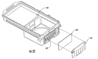
ある実施態様では、弁部材が引き込まれる際に(図25)周囲空気をハウジングに引き込むための通気口625、通気口膜626、通気口カバー627が組み込まれ得る。好適な通気口膜626は0.22ミクロン厚の無菌化用膜である。通気口625はハウジング内部に連通する複数の孔を含み得、前記孔は、雌型のハウジングから弁が引き込まれる際に生じる注射器効果により装置に空気を取り入れる通路を提供する。引き込まれた空気は通気口625を通して流動し、通気口膜626により無菌化される。ある実施態様では通気口膜626はハウジングにヒートシールされ得るが、ガスケットが使用され得、あるいはハウジング内のポートに既存のフィルタを装着できる。
In some embodiments, a vent 625,
移行装置の組み立てに際し、第1部材400及び第2部材320は図10Aに示すように90°を為すよう位置付け、各部材を、図10Bに示すように胴部材401上のヒンジピン408が胴部材301のスロット308に挿入され得るように係合させて胴部材301、401にするクラムシェル構造を形成する。部材320及び400のヒンジの対向する端部を、ヒンジピン408の軸を中心として図10Bに矢印で示すように回転させて相互に引き寄せてクラムシェルを閉じる。図10Cには、閉じた、組み立て位置が示される。前記位置では錠止用ハンドルアセンブリ310、410が合致され、かくして一方のハンドルを摺動作動すると他方も作動する。前記位置では弁はドア425、325により閉鎖され、流体は第1部材400及び第2部材320間を連通しない。
In assembling the transition device, the
第1及び第2部材又はハウジング400、320が結合すると各ピン312が第1部材400の各スロット403に入り、錠止部材405を軸方向に偏倚させて摺動自在のハンドルアセンブリ410の通路から押し出す。同様に、各ピン402が第2胴部材320の各スロット313に入り、錠止部材365を軸方向に偏倚させて摺動自在のハンドルアセンブリ310の通路から押し出す。ある実施態様では各錠止部材365、405は軸方向に偏倚可能な自由端を有する細長部材である。
When the first and second members or
第1及び第2部材又はハウジング400、320が係合すると錠止用ハンドルアセンブリ310、410が図10Cに示されるように左側に摺動作動される。ハンドルアセンブリの前記動作により第1及び第2部材又はハウジング400、320は相互錠止され、且つ、夫々の部材のドアが開放され、かくして第1及び第2部材又はハウジング400、320間に流体連通が確立される。流体連通が確立されると、以下に詳しく説明されるように第2部材320の弁部材が第1部材400の弁部材内に偏倚され得る。
When the first and second members or
図13A〜13Cには第1部材の弁部材450が例示される。フィッティング413が全体に円筒状の部材を含み、前記部材は軸方向に伸延する、遠位開口又は出口414を有する遠位自由端で終端され、軸方向に伸延する、第1部材400の円筒状部材404の上方自由端上に座着される(図12)近位自由端435で終端される。フィッティング413の遠位部分は近位自由端方向において半径方向外側に傾斜され、かくして肩部418を形成する。これにより形成される半径方向増厚部分がバーブ式フィッティングとしての作用を支援し、管あるいはその他への結合を容易化させる。フィッティング413は全体に切頭円錐状の部分436を含み、前記部分436は、図10Cに示される組み立て状況下に第1部材400の円筒状部材404のリム上に座着する半径方向に伸延する周囲方向フランジ437を有する。
13A to 13C illustrate a
ワイパーシール442は全体に円筒状の部材であり、半径方向外側に伸延する中間周囲フランジ477を含み、前記フランジはフィッティング413の下方に突出する部材439上に嵌合する偏倚用部材又はバネ479の座部として作用する。
The
ベース部480は、O−リング486の支援下に内側のワイパーシール442をシールする上方円筒部分を有する。ベース部480の下方領域484は、図示された実施態様ではベース部480から軸方向に伸延する半球形状を有する、下向きのデプレッサ部材481を含む。前記デプレッサ部材は、第2部材320の相当する弁部材350のポペット560を前記弁部材の作動時に以下に詳しく説明するように偏倚させるよう機能する。
The
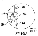
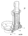
図14A〜14Eには、第2部材又はハウジング320の弁部材350が示される。弁部材350は上方内側胴部510を含む。上方内側胴部510は全体に円筒状の部材を含み、前記部材は、軸方向に伸延する、遠位開口又は出口514を有する遠位自由端で終端され、且つ、軸方向に伸延する、近位端開口535を有する近位自由端で終端される。内側胴部510の遠位部分は近位端方向で半径方向外側に傾斜されて肩部518を形成する。これにより形成される半径方向増厚部分がバーブ式のフィッティングとしての作用を支援し、管あるいはその他への結合を容易化させる。
14A-14E, the second member or
弁部材350はポペット560をも含み、前記ポペットは、中実ベース部561と、前記ベース部561から軸方向に延びる離間された複数の脚部562をも含む。当業者には、脚部数は特に限定されないことを認識されよう。ベース部561は、以下に詳しく説明されるように、中央に位置付けられてデプレッサ部材481の突起482を受ける凹部559を含む。脚部562は、これら脚部562の内側に位置決めされた圧縮バネあるいはその他等の如き偏倚用部材580を保持する。偏倚用部材580の反対側端部は図14Dに詳細を示す内側胴部コネクタ594に座着される。内側胴部コネクタ594は中間環状リング593を含み、前記中間環状リングは、上方内側胴部510の下方縁部と、弁下方内側胴部575の上方縁部との間に座着される。中間環状リング593は半径方向内側に伸延して偏倚用部材580の座部を提供する。
The
弁外側スリーブ570は全体に円筒状部材であり、その下方端部位置に、第1部材400の全体に円筒状の部材404の相当する溝318(図12)に係合するネジ溝571を有する。上方内側胴部510の下方部分は、内側胴部コネクタ594、偏倚用部材580、ポペット560、及び下方内側胴部578がそうである様に、図14Cに示されるように弁外側スリーブ570の内側に座着される。下方内側胴部578は全体に円筒状を有し、図14Eに示されるように、その下方端位置には、ポペット560に接触シールされるオーバーモールドされたシール579を保持する半径方向内側に伸延するフランジ577を含む。
The valve
ある実施態様では弁部材350、450は、軸方向負荷が付加されると相互の内部に直線的に相対偏倚される。ある実施態様では第2部材320の弁部材350は第1部材400の弁部材450内に直線的に偏倚され、その後、第2部材320の弁部材350をノブ599により回転させる等により各弁部材が相対回転されることで弁部材350が弁部材450内へと更に偏倚される。前記回転により、弁外側スリーブ570の単数あるいは複数のネジ溝571が弁部材450の円筒状部材404の相当する単数あるいは複数の溝318に係合する。相対回転させ続けて弁部材350を弁部材450内に更に偏倚させるとデプレッサ部材481がポペット560に接触し、前記ポペットが偏倚用部材580の偏倚に抗して第1方向に偏倚される。更に回転すると弁部材350のネジ溝端がワイパーシール442の半径方向フランジ477に係合し、前記フランジが偏倚部材479の偏倚に抗して第2方向に偏倚される。ある実施態様では第1及び第2方向は逆方向である。ポペット560及びワイパーシール442が偏倚されると弁部材350、450間を貫く流体連通が創出される。
In one embodiment, the
図15及び16にはある実施態様に従う流体移行装置の第2別態様が例示される。前記第2別態様の実施態様における弁作動は第1別態様におけるそれと類似のものであり、第1及び第2部材又はハウジングが係合し且つ錠止されると加圧下の無菌流体連通が確立され、弁部材の一方が他方の内部に偏倚され得る。主な相違点は胴部材又はハウジングの形態と、各部材の係合の仕方にある。例えば、図15及び16の実施態様は、胴部材又はハウジングがフェース上でカム錠止(図16)した後、ピン及びフック特徴部が整列することが含まれる。 15 and 16 illustrate a second alternative embodiment of a fluid transfer device according to an embodiment. The valve actuation in the second alternative embodiment is similar to that in the first alternative, and aseptic fluid communication under pressure is established when the first and second members or housings are engaged and locked. And one of the valve members can be biased inside the other. The main difference is in the form of the body member or housing and the manner of engagement of each member. For example, the embodiment of FIGS. 15 and 16 includes the pin and hook features aligning after the barrel member or housing is cam-locked on the face (FIG. 16).
詳しくは、図15及び16には第1部材又はハウジング400’と、第2部材又はハウジング300’とが組み立て状況で示される。弁部材350’及び450’は第1実施態様における弁部材350及び450と同一あるいは本来同一であるからここでは詳しく説明されない。
Specifically, FIGS. 15 and 16 show the first member or housing 400 'and the second member or housing 300' in an assembled state. Since the
弁部材のハウジング(図16では弁部材が配置されない状態で示される)は第1部材又はハウジング400’を含み、前記ハウジングは、第2部材又はハウジング300’における類似形状の底部領域に相当する形状の底部領域を有する胴部材401’を有し、かくして第1及び第2部材を合致させ得る。各部材400’、300’は上部プレートを含む。ある実施態様では各部材400’、300’は、他方の部材上の各カム部材(第2部材300’における一方のみが番号391’で示される)を受けるカムスロット(第1部材400’における一方のみが番号490’で示される)を含み、各カム部材は2つの部材400’、300’を係合させ且つ逆向に捻って相互錠止させると各カムスロットに受けられる。各部材300’、400’は各ドア325’、425’に装着されたレバーアーム303’、404’を夫々担持する。各レバーアームはドアの開閉位置間で回転自在である。第1胴部材401’のレバーアーム403’は軸方向に延びる中空脚部426’を有し、前記中空脚部は第2部材301’から軸方向に延びるピン(図示せず)と合致する。同様に、第2胴部材301’のレバーアーム303’は軸方向に延びる中空脚部326’を有し、前記中空脚部は第1部材401’の底部から軸方向に延びるピン(図示せず)と合致する。
The valve member housing (shown in FIG. 16 with no valve member disposed) includes a first member or
ある実施態様では各胴部材401’、301’は底部プレートを有し、前記底部プレートは、各ドア425’、325’により常閉される弁ポートを有する。各部材が組み立てられると弁ポートは整列する。
図17には弁アイソレータベローズアセンブリ700が例示される。アセンブリ700はベローズ710を含み、前記ベローズはシール保持部材711(図17A)により保持される。シール保持部材711は、ベローズ710を固定する第1リング711Aと、カム部材720に結合する第2リング711Bとを含む。第1リング711Aは、半径方向内側に延びてベローズ710を保持するよう作用する交互する上部及び底部フランジ712A、712Bを含む。ドア325’も、カム部材720に結合するリングを有する。ドア325’及びシール保持部材711はカム720が回転すると一緒に移動する。ある実施態様ではカム720は全体に円筒状を有し、その外側側面に形成された複数のカムスロット又は溝721(図17及び19Aの各々に一方が示される)を含む。シール保持部材711の第2リング711B上には、離間された相当するピン713が半径方向内側に伸延され、各ピンはカム720の各カムスロット721内を移動する。ある実施態様では第2リング711Bは3本の前記ピン713を含み、カム720は、各1つが前記各ピンに相当する3つの前記カムスロット721を含む。
In one embodiment, each barrel member 401 ', 301' has a bottom plate that has a valve port normally closed by each door 425 ', 325'. The valve ports are aligned as each member is assembled.
FIG. 17 illustrates a valve isolator bellows
ある実施態様ではドア325’はピン(図示せず)を含み、前記ピンはその底部から軸方向下方に伸延して部材400’のベース部307’の孔306’(図20)に合致する。図17Bに示されるように、ドアは軸方向に延びるボタン327と、軸方向に伸延する離間された複数(図では3つが示される)ウィング327Aとを含み、前記ウィングはボタン327を包囲するがボタンの高さまでは伸延されない。ボタン327及びウィング327Aはカム720の下側の開放領域331に嵌入されて且つこの領域に係合し、前記開放領域331は、図17Bに実線矢印で示すようにドア325’上のウィング327A間の空間333に嵌入する。ある実施態様では、カム720はキー付きピン723を含み、前記キー付きピンはその上面から軸方向上方に伸延してレバーアーム303’と合致する。レバーアーム303’が回転するとカム720が相当分回転される。カムが回転するとドア325’が開放位置から閉鎖位置(及びその逆)に移動され、かくして、以下に詳しく説明されるように、保持部材711がカムのカムスロット721内に載置されるに従いベローズ710が垂直移動される。
In one embodiment, the door 325 'includes a pin (not shown) that extends axially downward from its bottom to fit into the hole 306' (FIG. 20) in the base portion 307 'of the member 400'. As shown in FIG. 17B, the door includes an
図17にはドア325’とベローズ710とが閉鎖位置で例示される。前記位置ではドア325’は弁部材間の流体連通を防止し、ベローズ710がドア325’に接触シールされる。レバーアーム303’が図18A及び18Bに示されるように回転されると、レバーアームに連結されたカム720も回転され、かくしてドアが開放されて保持部材711がカムスロット721内に載置され、かくして、先ず軸方向上方に移動し、次いで、ベローズシールがドアから剥がれるに従い、前記ベローズを胴部材301’のポート方向で軸方向下方に移動させる。レバーアーム303’が回転し続けるとドアは図19A及び19Bに示すようにその完全開放位置に移動され、かくしてベローズをその最下方の、弁シール位置に(カムスロット721内を移動することによりガイドされつつ)到達させる。前記位置ではベローズは弁ポートを覆い且つ底部プレート380’に接触シールされ、かくして弁部材を汚染から保護する。
ベローズアセンブリは部材又はハウジング320に関して示されたがある実施態様では両ハウジングは共に、結合中のそれら各々の弁を隔絶させるベローズアセンブリを含む。
FIG. 17 illustrates the
In some embodiments, the bellows assembly is shown with respect to the member or
図21A及び21Bには、閉鎖位置を取る弁部材、即ち、ドア325’がベローズ710がドア325’に接触する状態で弁ポートを覆って位置決めされた弁部材を備える流体移行装置が例示される。図22A及び22Bに示されるように、第1及び第2部材又はハウジングを逆方向に捻ってそれらを相互に錠止させるとドア325’はその開放位置に回転し始める。ピンがカムスロットに載置されるとベローズシール保持部材711も回転し始め、ベローズシール710がドア325’から剥がれる。図23A及び23Bに示されるように回転が継続されるとドア325’がベローズシール710を越えて回転される。シール保持部材711のピンは、カムスロット内を移動し続けてベローズシール710を底部プレート380’方向に降下させる。図24A及び25Bにはドア325’及びベローズ710の回転完了時の位置が示される。ドア325’は完全開放位置を取り、弁ポート395’はドアで遮られない。その他部材又はハウジングにおいて類似のドア作動が同時に生じ、かくして、2つの部材又はハウジング間の流体が連通され得る。ベローズ710はハウジングの底部プレート380’に接触シールされる。ハウジングは今や相互錠止され、弁ポートは開放され、弁部材はその一方が他方の内部に軸方向で相対偏倚されることで係合され得る。
21A and 21B illustrate a fluid transfer device comprising a valve member that is in a closed position, i.e., a valve member that is positioned over the valve port with the door 325 'contacting the door 325' with the
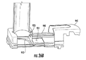
図26には別態様が例示され、各ドアは閉鎖位置で相互に密接状態とされ、かくしてそれらの間におけるデッド容積が減少又は排除される。ある実施態様では各ドアアセンブリはフェースプレート部材910を含み、前記フェースプレート部材は、その周囲に沿って嵌着されたガスケット912を有し得る開口911を含む。フェースプレート部材910は、その表面から上方に伸延する対向する一対の、細長の側方トラック部材913、914を含む。ある実施態様では各トラック部材913、914は中間切り欠き915を含み、前記中間切り欠きは、ドア閉鎖時にプラグピン932a−dでドアを押してドアをフェースと面一化させ、ドア開放時には引き込まれるカムを創出する。各トラック部材913、914は端部傾斜部960をも含み、ドアがカム作用によりその閉鎖位置又は開放位置に来ると前記プラグピンの2つが前記端部傾斜部の上部に載置される。前記中間切り欠き及び端部傾斜部が、カム624の合致するトラック(図25)と協働してプラグピンを一緒に捕捉し、あるカム624がドアを前方に押して閉鎖させ、カバー上の合致するレールがドアを後方に押して開放させる。ある実施態様では各トラック913、914は、各トラック部材と側方縁部との間の領域が各トラック部材と共に、ドアアセンブリが載置されるL字形トラックを形成するようにフェースプレート部材910の側縁部の若干内側に位置決めされる。ある実施態様ではキャリヤ部材920はプラグ930を担持するように構成され、且つ、図示されるように、上方に延びる4つの側壁931a−dを含む。キャリヤ部材920は、図26Aに示すようにスロット付き軸940を受ける、上方に延びる切り欠き付きタブ923をも含む。プラグ930は、ガスケット912の支援下に開口911をシールする形状を有する、下方に突出する中実の円筒状部分931を含む。
FIG. 26 illustrates another embodiment, where the doors are in close proximity to each other in the closed position, thus reducing or eliminating dead volume therebetween. In one embodiment, each door assembly includes a
図26Bに示されるように、ハンドル945はハウジング上に摺動してL字形状のトラック内に載置される。ハンドル945の端部フェースのスロット946(図26)は軸940と係合する。ベローズ947は軸940を包入する。ハンドル945を閉鎖位置にすると、図26Cに示すようにプラグ930が部材910の開口911を越えて開放位置から閉鎖位置に移動される。プラグ930は今やコネクタハウジングのフェースと面一化され、前記プラグと、他のハウジング部材のプラグ(類似設計の)との間に捕捉されるデッド容積が減少あるいは排除される。
以上、本発明を実施例を参照して説明したが、本発明の内で種々の変更をなし得ることを理解されたい。
As shown in FIG. 26B, the
Although the present invention has been described with reference to the embodiments, it should be understood that various modifications can be made within the present invention.
1 第1無菌ハウジングプレート/無菌ハウジングプレート
2 ドア
3 第1胴部材/胴部材
4 第1バヨネットリング/バヨネットリング
5 ドアレバー
6 カバー
7 内側胴部材
8 弁遮断スリーブ/スリーブ
9 バネ
12 ワイパーシール
13 第1ベース部/ベース部
19 第2無菌ハウジングプレート/プレート/無菌ハウジングプレート
21 孔
22 第2ドア/ドア
23 ポート
24 軸部材
26 ドア軸シール
30 ポート
31 孔
32 軸部材
33 孔
41 肩部
50 内側スリーブ
50A 管状部材
50B シール/オーバーモールドシール
60 ポペット
61 ベース部
62 脚部
70 コネクタ胴部
71 環状フランジ
77 円筒状外側フランジ
80 突起
90 内側胴部
91 下方円筒状部分
92 中間切図円錐状部分
93 上方円筒状部分
94 肩部
100 ハウジング/第1部材
110 第2部材弁スリーブ/弁スリーブ
111 近位自由端
112 外側ネジ溝/ネジ溝
113 円筒状部材
114 出口
115 近位端
116 切図円錐状部分
117 周囲フランジ
118 肩部
119 環状溝
127 O−リング
130 円筒状部材
140 ナット
141 突起
150 第2胴部
151 ベース部
152 リブ環状肩部/肩部
153 外側環状リム/リム
155 タブ
200 第2部材/ハウジング
203 ポート
213 溝/周囲方向溝
216 遠位自由端
217 スロット
300 ベース部
301 胴部材
302 外側リム
303 ポート
304 円筒状部材
305 内側溝/溝
308 スロット
310 錠止用ハンドルアセンブリ/ハンドルアセンブリ
311 底部無菌フェース
312 ピン
313 各スロット
315 ハンドル部材
316 ドア軸
317 L字形フランジ
318 溝
320 ハウジング/第2部材/部材/第2胴部材
325 ドア
326 ドアストッパ
327 ボタン
327A ウィング
328 ワイパーシール
329 オーバーモールドガスケット
350 弁部材
365 錠止部材
400 ハウジング/第1部材
401 胴部材
402 ピン
403 スロット
404 円筒状部材
405 錠止部材
406 スロット
407 停止部材
408 ヒンジピン
409 L字形部材
410 錠止用ハンドルアセンブリ/ハンドルアセンブリ/胴部材
411 底部無菌フェース/無菌プレート
413 フィッティング
414 出口
415 ハンドル部材
416 ドア軸
417 L字形フランジ/フランジ
418 肩部
419 無菌プレートガスケット
420 内側肩部
425 ドア
426 ドアストッパ
428 ワイパーシール
429 ガスケット
435 近位自由端
437 周囲方向フランジ
442 ワイパーシール
450 弁部材
460 スロット
477 中間周囲フランジ/半径方向フランジ
479 バネ
480 ベース部
481 デプレッサ部材
482 突起
484 下方領域
486 O−リング
510 上方内側胴部/内側胴部
514 出口
518 肩部
535 近位端開口
559 凹部
560 ポペット
561 中実ベース部/ベース部
562 脚部
570 弁外側スリーブ
571 ネジ溝
575 弁下方内側胴部
577 フランジ
578 下方内側胴部
579 シール
580 偏倚用部材
593 中間環状リング
594 内側胴部コネクタ
599 ノブ
610 ベース部
612 環状リム
615 孔
624 カム
625 通気口
626 通気口膜
627 通気口カバー
700 弁アイソレータベローズアセンブリ/アセンブリ
710 ベローズ/ベローズシール710
711 シール保持部材/ベローズシール保持部材/保持部材
711A 第1リング
711B 第2リング
712A 底部フランジ
713 ピン
720 カム部材/カム
721 溝/カムスロット
723 ピン
800 バネ
910 フェースプレート部材/部材
911 開口
912 ガスケット
913 側方トラック部材
920 キャリヤ部材
923 タブ
930 プラグ
940 軸
945 ハンドル
946 スロット
947 ベローズ
960 端部傾斜部
DESCRIPTION OF SYMBOLS 1 1st aseptic housing plate / aseptic housing plate 2 door 3 1st trunk member / body trunk 4 first bayonet ring / bayonet ring 5 door lever 6 cover 7 inner trunk member 8 valve shut-off sleeve / sleeve 9 spring 12 wiper seal 13 first Base part / base part 19 Second aseptic housing plate / plate / aseptic housing plate 21 hole 22 second door / door 23 port 24 shaft member 26 door shaft seal 30 port 31 hole 32 shaft member 33 hole 41 shoulder 50 inner sleeve 50A Tubular member 50B Seal / overmold seal 60 Poppet 61 Base portion 62 Leg portion 70 Connector body portion 71 Annular flange 77 Cylindrical outer flange 80 Projection 90 Inner body portion 91 Lower cylindrical portion 92 Middle cut conical portion 93 Upper cylindrical shape Part 94 shoulder 100 housing First member 110 second member valve sleeve / valve sleeve 111 proximal free end 112 outer thread / thread 113 cylindrical member 114 outlet 115 proximal end 116 cutaway conical portion 117 peripheral flange 118 shoulder 119 annular Groove 127 O-ring 130 Cylindrical member 140 Nut 141 Protrusion 150 Second body 151 Base 152 Rib annular shoulder / shoulder 153 Outer annular rim / rim 155 Tab 200 Second member / housing 203 Port 213 Groove / circumferential direction Groove 216 distal free end 217 slot 300 base 301 barrel member 302 outer rim 303 port 304 cylindrical member 305 inner groove / groove 308 slot 310 locking handle assembly / handle assembly 311 bottom sterile face 312 pin 313 each slot 315 handle Member 316 Door shaft 17 L-shaped flange 318 groove 320 housing / second member / member / second barrel member 325 door 326 door stopper 327 button 327A wing 328 wiper seal 329 overmold gasket 350 valve member 365 locking member 400 housing / first member 401 trunk Member 402 Pin 403 Slot 404 Cylindrical member 405 Locking member 406 Slot 407 Stopping member 408 Hinge pin 409 L-shaped member 410 Locking handle assembly / handle assembly / body member 411 Bottom aseptic face / sterile plate 413 Fitting 414 Exit 415 Handle member 416 Door shaft 417 L-shaped flange / flange 418 Shoulder 419 Sterile plate gasket 420 Inner shoulder 425 Door 426 Door stopper 428 Wiper seal 4 9 Gasket 435 Proximal free end 437 Peripheral flange 442 Wiper seal 450 Valve member 460 Slot 477 Intermediate peripheral flange / radial flange 479 Spring 480 Base 481 Depressor member 482 Protrusion 484 Lower region 486 O-ring 510 Upper inner barrel / Inner trunk 514 Exit 518 Shoulder 535 Proximal end opening 559 Recess 560 Poppet 561 Solid base / base 562 Leg 570 Valve outer sleeve 571 Screw groove 575 Valve lower inner trunk 577 Flange 578 Lower inner trunk 579 Seal 580 Biasing member 593 Intermediate annular ring 594 Inner trunk connector 599 Knob 610 Base portion 612 Annular 615 615 Hole 624 Cam 625 Vent 626 Vent membrane 627 Vent cover 700 Valve isolator bellows assembly / Assembly 710 Bellows / Bellows seal 710
711 seal holding member / bellows seal holding member / holding
Claims (16)
第1胴部材を含む第1部材にして、前記第1胴部材が、第1弁ポート、第1弁ポート開放位置及び第1弁ポート閉鎖位置間で作動され得る第1ドア、第1錠止用ハンドルアセンブリ、第1弁部材、を含む第1部材と、
第2胴部材を含む第2部材にして、前記第2胴部材が、第2弁ポート、第2弁ポート開放位置及び第2弁ポート閉鎖位置間で作動され得る第2ドア、第2錠止用ハンドルアセンブリ、第2弁部材、を含む第2部材と、
を含み、
前記第1部材及び第2部材は、前記第1部材及び第2部材を相対回転させることにより係合できるように回動可能に連結され、前記第1及び第2錠止用ハンドルアセンブリの作動は、前記第1部材及び第2部材を相互錠止させ、前記第1ドアを前記第1弁ポート開放位置に作動させ、前記第2ドアを前記第2弁ポート開放位置に作動させ、
前記第1及び第2部材間に流体連通を創出する流体移行装置。 A fluid transfer device comprising:
A first member including a first body member, wherein the first body member can be operated between a first valve port, a first valve port open position, and a first valve port closed position, and a first lock. A first member including a handle assembly, a first valve member;
A second member including a second body member, wherein the second body member is operable between a second valve port, a second valve port open position, and a second valve port closed position; a second lock; a second member including use handle assembly, the second valve member,
Including
The first member and the second member are rotatably connected so that they can be engaged by rotating the first member and the second member relative to each other, and the operation of the first and second locking handle assemblies is performed. The first member and the second member are locked together, the first door is operated to the first valve port open position, the second door is operated to the second valve port open position,
To that flow transit device creates fluid communication between the first and second members.
第1弁ポートを有する第1胴部材、第1弁ポートの開閉位置間を作動自在の第1ドア、を含み且つ前記第1弁部材と第1錠止用ハンドルアセンブリを有する第1ハウジングを提供するステップ、
第2弁ポートを有する第2胴部材、第2弁ポートの開閉位置間を作動自在の第2ドア、を含み且つ前記第2弁部材と第2錠止用ハンドルアセンブリを有する第2ハウジングを提供するステップ、
前記第1及び第2ハウジングを連結するステップ、
前記第1ハウジングと前記第2ハウジングとを相対回転させることによって前記第1ハウジングと前記第2ハウジングとを互いに係合させるステップ、
前記第1及び第2錠止用ハンドルアセンブリの作動により前記第1及び第2ハウジングを相互錠止して前記第1及び第2ドアをその各弁ポート開放位置に作動させるステップ、
を含む方法。 A method of creating a sterile connection between a first and second valve member of a fluid transfer device, comprising:
Provided is a first housing including a first body member having a first valve port, a first door operable between opening and closing positions of the first valve port, and having the first valve member and a first locking handle assembly. Step to do,
A second housing including a second body member having a second valve port, a second door operable between opening and closing positions of the second valve port, and having the second valve member and a second locking handle assembly. steps that,
Connecting the first and second housings;
Engaging the first housing and the second housing with each other by rotating the first housing and the second housing relative to each other;
Actuating the first and second locking handle assemblies to lock the first and second housings and actuate the first and second doors to their respective valve port open positions;
Including methods.
Applications Claiming Priority (3)
| Application Number | Priority Date | Filing Date | Title |
|---|---|---|---|
| US201361806442P | 2013-03-29 | 2013-03-29 | |
| US61/806,442 | 2013-03-29 | ||
| PCT/US2014/031829 WO2014160756A1 (en) | 2013-03-29 | 2014-03-26 | Sterile connection/disconnection coupling and method |
Publications (2)
| Publication Number | Publication Date |
|---|---|
| JP2016517936A JP2016517936A (en) | 2016-06-20 |
| JP6345764B2 true JP6345764B2 (en) | 2018-06-20 |
Family
ID=51625488
Family Applications (1)
| Application Number | Title | Priority Date | Filing Date |
|---|---|---|---|
| JP2016505544A Active JP6345764B2 (en) | 2013-03-29 | 2014-03-26 | Aseptic joint and method |
Country Status (9)
| Country | Link |
|---|---|
| US (3) | US9901729B2 (en) |
| EP (2) | EP3682939B1 (en) |
| JP (1) | JP6345764B2 (en) |
| KR (1) | KR101769752B1 (en) |
| CN (2) | CN109458465B (en) |
| CA (2) | CA2906223C (en) |
| ES (2) | ES2939536T3 (en) |
| SG (2) | SG10201803735WA (en) |
| WO (1) | WO2014160756A1 (en) |
Families Citing this family (24)
| Publication number | Priority date | Publication date | Assignee | Title |
|---|---|---|---|---|
| US10773863B2 (en) | 2011-06-22 | 2020-09-15 | Sartorius Stedim North America Inc. | Vessel closures and methods for using and manufacturing same |
| CN109458465B (en) | 2013-03-29 | 2020-03-06 | Emd密理博公司 | Aseptic connect/disconnect coupling and method |
| EP3286475B1 (en) | 2015-04-20 | 2021-05-19 | Colder Products Company | Single-use aseptic fluid couplings |
| WO2017015137A1 (en) * | 2015-07-17 | 2017-01-26 | Parker-Hannifin Corporation | Sterile fluid connection |
| EP3359242B1 (en) * | 2015-10-08 | 2023-12-06 | Colder Products Company | Reusable aseptic fluid couplings |
| US10173046B2 (en) | 2016-01-19 | 2019-01-08 | Wilmarc Holdings, Llc | Connector system for releasably connecting fluid conduits |
| EP3293524B1 (en) * | 2016-09-12 | 2021-06-09 | Stratec SE | Fluidic coupling |
| US11691866B2 (en) | 2017-11-14 | 2023-07-04 | Sartorius Stedim North America Inc. | System for simultaneous distribution of fluid to multiple vessels and method of using the same |
| US11577953B2 (en) | 2017-11-14 | 2023-02-14 | Sartorius Stedim North America, Inc. | System for simultaneous distribution of fluid to multiple vessels and method of using the same |
| WO2019099406A1 (en) | 2017-11-14 | 2019-05-23 | Sartorius Stedim North America Inc. | Fluid transfer assembly with a junction having multiple fluid pathways |
| US11319201B2 (en) | 2019-07-23 | 2022-05-03 | Sartorius Stedim North America Inc. | System for simultaneous filling of multiple containers |
| CN108785848B (en) * | 2018-09-07 | 2023-11-21 | 临沂市兴华医用器材有限公司 | Anesthesia catheter connector |
| CA3124263A1 (en) * | 2018-12-20 | 2020-06-25 | Centre For Commercialization Of Regenerative Medicine | Systems and methods for a reusable, aseptic connector |
| DE102019108664A1 (en) * | 2019-04-03 | 2020-10-08 | Sartorius Stedim Biotech Gmbh | Sterile connector for the sterile transfer of a liquid medium |
| US11435019B2 (en) * | 2019-07-25 | 2022-09-06 | Eaton Intelligent Power Limited | Valve guide with integral assembly support |
| WO2021138436A1 (en) | 2019-12-31 | 2021-07-08 | Colder Products Company | Aseptic fluid couplings |
| US11384883B2 (en) * | 2020-01-31 | 2022-07-12 | General Electric Company | Cryogenic transfer line coupling assembly |
| CN115768512A (en) | 2020-06-11 | 2023-03-07 | 考尔得产品公司 | Disposable breakaway fluid coupling |
| CN116848349A (en) * | 2021-02-08 | 2023-10-03 | 考尔得产品公司 | Fluid coupling |
| WO2022197886A1 (en) * | 2021-03-19 | 2022-09-22 | Sunflower Therapeutics, Llc | Aseptic connector for fluid conduits |
| CN117677422A (en) * | 2021-06-17 | 2024-03-08 | 考尔得产品公司 | Aseptic liquid coupling |
| WO2023136928A1 (en) * | 2022-01-11 | 2023-07-20 | Emd Millipore Corporation | Sterile fluidic connector with reconnectable connectors and method of aseptic connection |
| WO2023229704A1 (en) * | 2022-05-23 | 2023-11-30 | Colder Products Company | Aseptic fluid couplings |
| GB2620435A (en) * | 2022-07-08 | 2024-01-10 | Watson Marlow Ltd | Aseptic connector |
Family Cites Families (69)
| Publication number | Priority date | Publication date | Assignee | Title |
|---|---|---|---|---|
| US263330A (en) * | 1882-08-29 | Device for controlling and regulating the flow of oil-wells | ||
| US950263A (en) * | 1909-05-26 | 1910-02-22 | Fred H Harpster | Automatic pipe-coupling for cars. |
| US2073048A (en) * | 1936-02-15 | 1937-03-09 | Fred I Clark | Selective volume control valve |
| US2317827A (en) * | 1942-01-09 | 1943-04-27 | Thompson Prod Inc | Quick disconnect coupling |
| US2333496A (en) * | 1942-08-05 | 1943-11-02 | Thompson Prod Inc | Quick disconnect coupling |
| US2399516A (en) * | 1943-10-11 | 1946-04-30 | Thompson Prod Inc | Quick disconnect coupling |
| US2399525A (en) * | 1943-12-04 | 1946-04-30 | Thompson Prod Inc | Quick disconnect coupling |
| US2403620A (en) * | 1943-12-11 | 1946-07-09 | Thompson Prod Inc | Aligning and detent means for quick disconnect couplings |
| US2779608A (en) * | 1952-05-24 | 1957-01-29 | Aeroquip Corp | Combined gate valve and coupling |
| US2757941A (en) * | 1952-06-06 | 1956-08-07 | Aeroquip Corp | Coupling with sliding seal and locking device |
| US2709090A (en) * | 1952-06-25 | 1955-05-24 | Aeroquip Corp | Sliding plate type coupling with slide plate locking pins |
| US2828146A (en) * | 1952-10-08 | 1958-03-25 | Aeroquip Corp | Coupling with sliding seal plates |
| US2687903A (en) * | 1952-12-22 | 1954-08-31 | Aeroquip Corp | Coupling with sliding valves and locking keys |
| US2749146A (en) * | 1953-04-02 | 1956-06-05 | Aeroquip Corp | Coupling with rotary sliding seal |
| US2823887A (en) * | 1955-09-29 | 1958-02-18 | Joseph S Osinski | Hose or pipe coupling with cut-off valve |
| US3106223A (en) * | 1959-02-02 | 1963-10-08 | Apv Co Ltd | Disconnectable coupling |
| US3357452A (en) * | 1965-10-01 | 1967-12-12 | Lockheed Aircraft Corp | Quick-disconnect coupling |
| US3909910A (en) * | 1973-03-29 | 1975-10-07 | Union Carbide Corp | Method of joining the ends of two conduits together in a sterile manner |
| US4022205A (en) * | 1973-11-05 | 1977-05-10 | Tenczar Francis J | Fluid connectors |
| US4019512A (en) | 1975-12-04 | 1977-04-26 | Tenczar Francis J | Adhesively activated sterile connector |
| US4089506A (en) * | 1977-01-24 | 1978-05-16 | American Hospital Supply Corporation | Gate valve |
| US4306705A (en) * | 1979-01-22 | 1981-12-22 | Svensson Jan A | Slide valve and coupler assembly |
| US4334551A (en) * | 1979-04-30 | 1982-06-15 | Becton Dickinson & Company | Connector |
| US4271865A (en) * | 1979-05-14 | 1981-06-09 | Galloway Robert L | Dry break coupling valve |
| US4253684A (en) | 1979-05-14 | 1981-03-03 | Monsanto Company | Quick connect coupler with air shield |
| US4275763A (en) * | 1979-05-25 | 1981-06-30 | Standard Oil Company (Indiana) | Double-slide valve |
| US4418945A (en) * | 1981-06-08 | 1983-12-06 | International Business Machines Corporation | Sterile connectors |
| IL66276A0 (en) * | 1982-07-08 | 1982-11-30 | Plasson Maagan Michael Ind Ltd | Control device particularly useful as manual slide valve |
| US4509554A (en) * | 1982-11-08 | 1985-04-09 | Failla William G | High and low pressure, quick-disconnect coupling |
| NL8300386A (en) * | 1983-02-02 | 1984-09-03 | Steritech Bv | STERILE DEVICE CONNECTING TWO ROOMS. |
| EP0165926B1 (en) * | 1983-05-20 | 1990-10-24 | Bengt Gustavsson | A device for transferring a substance |
| SE449030B (en) * | 1983-12-19 | 1987-03-30 | Jan Axel Svensson | FLOOD CONTROL VALVE VALVE AND CLUTCH UNIT |
| IT1218077B (en) * | 1988-06-15 | 1990-04-12 | Dideco Spa | FLUID INTERCEPTION DEVICE IN A LINE |
| US4989638A (en) * | 1989-12-21 | 1991-02-05 | Allied-Signal | Substantially leak-free disconnection apparatus |
| US5092363A (en) * | 1990-01-16 | 1992-03-03 | Ingersoll-Rand Company | Quick and dry coupling |
| US5009252A (en) * | 1990-05-03 | 1991-04-23 | The United States Of America As Represented By The Secretary Of The Army | Air distribution connector valve |
| US5039063A (en) * | 1990-07-13 | 1991-08-13 | Marathon Oil Company | Smooth bore slide valve |
| US5165439A (en) * | 1990-12-14 | 1992-11-24 | Witold Krynicki | Frangible connectors |
| IT1270206B (en) | 1994-06-10 | 1997-04-29 | Faster Srl | QUICK COUPLING FOR UNDER PRESSURE FLUIDS |
| DE4443714C2 (en) | 1994-12-09 | 1996-10-17 | Fresenius Ag | Device for controlling a fluid flow |
| US5492147A (en) | 1995-01-17 | 1996-02-20 | Aeroquip Corporation | Dry break coupling |
| US5738143A (en) * | 1996-08-08 | 1998-04-14 | The United States Of America As Represented By The Secretary Of The Army | Butterfly actuated quick coupling connector valve |
| EP1716885A3 (en) | 1997-05-09 | 2006-11-15 | Pall Corporation | Connector assemblies, fluid systems, and methods for making a connection |
| US5884648A (en) * | 1997-08-27 | 1999-03-23 | Scholle Corporation | Coupling valve apparatus and method |
| US6077259A (en) | 1998-09-30 | 2000-06-20 | Becton, Dickinson And Company | Contamination resistant connector |
| US6394132B1 (en) * | 1999-11-24 | 2002-05-28 | Richard O. Walcome | Deck wash valve |
| US6679529B2 (en) | 2001-08-06 | 2004-01-20 | Theodore D. Johnson | Connection system |
| US6964406B2 (en) | 2001-08-10 | 2005-11-15 | Alaris Medical Systems, Inc. | Valved male luer |
| US6745998B2 (en) | 2001-08-10 | 2004-06-08 | Alaris Medical Systems, Inc. | Valved male luer |
| US7350535B2 (en) * | 2002-04-26 | 2008-04-01 | Gl Tool And Manufacturing Co. Inc. | Valve |
| DK1499382T3 (en) | 2002-04-26 | 2007-05-07 | Gl Tool And Mfg Co Inc | A valve |
| US7137974B2 (en) | 2002-07-26 | 2006-11-21 | Almasian Joseph M | Sterile connector |
| JP4451706B2 (en) * | 2004-04-28 | 2010-04-14 | 東洋エンジニアリング株式会社 | Piping connection device |
| AU2011211445A1 (en) | 2004-12-10 | 2011-09-01 | Carefusion 303, Inc. | Self-sealing male luer connector with multiple seals |
| US7396051B2 (en) * | 2005-01-14 | 2008-07-08 | Baxa Corporation | Swabable fluid connectors and fluid connector pairs |
| SE0500494L (en) | 2005-03-04 | 2005-12-13 | Novaseptic Ab | Method and apparatus for tightly interconnecting the ends of elongated elements such as hoses or lines |
| US7708025B2 (en) | 2005-03-07 | 2010-05-04 | Colder Products Company | Poppet valve member |
| DE102005020647B4 (en) * | 2005-05-03 | 2013-11-28 | Sartorius Stedim Biotech Gmbh | Connector, connector system and method of sterile connection |
| GB0605531D0 (en) | 2006-03-20 | 2006-04-26 | Powder Systems Ltd | Improvements Relating To Valves |
| SG153002A1 (en) * | 2007-11-16 | 2009-06-29 | Millipore Corp | Fluid transfer device |
| CN102215903B (en) * | 2008-03-25 | 2014-08-06 | 美国圣戈班性能塑料公司 | Connector assembly |
| DE202009008274U1 (en) | 2009-06-10 | 2009-09-10 | Heinz Meise Gmbh | Device for the sterile connection of medical disposable articles |
| SG184479A1 (en) * | 2010-04-05 | 2012-11-29 | Py Daniel C | Aseptic connector with deflectable ring of concern and method |
| FR2958365B1 (en) * | 2010-04-06 | 2012-05-11 | Millipore Corp | CONNECTING DEVICE AND CONNECTING SYSTEM COMPRISING SAME |
| CN201916514U (en) * | 2010-08-13 | 2011-08-03 | 钟国芳 | Ceramic shunt valve of single tube water inlet fast water heater |
| US8746278B2 (en) * | 2010-08-20 | 2014-06-10 | Daniel Py | Connector and related method |
| GB201103068D0 (en) | 2011-02-22 | 2011-04-06 | The Technology Partnership | Aseptic sampling system |
| CN109458465B (en) | 2013-03-29 | 2020-03-06 | Emd密理博公司 | Aseptic connect/disconnect coupling and method |
| WO2017015137A1 (en) * | 2015-07-17 | 2017-01-26 | Parker-Hannifin Corporation | Sterile fluid connection |
-
2014
- 2014-03-26 CN CN201810448671.2A patent/CN109458465B/en active Active
- 2014-03-26 CA CA2906223A patent/CA2906223C/en active Active
- 2014-03-26 ES ES20162113T patent/ES2939536T3/en active Active
- 2014-03-26 SG SG10201803735WA patent/SG10201803735WA/en unknown
- 2014-03-26 WO PCT/US2014/031829 patent/WO2014160756A1/en active Application Filing
- 2014-03-26 EP EP20162113.3A patent/EP3682939B1/en active Active
- 2014-03-26 CN CN201480019424.0A patent/CN105247257B/en active Active
- 2014-03-26 SG SG11201507290UA patent/SG11201507290UA/en unknown
- 2014-03-26 CA CA2983222A patent/CA2983222C/en active Active
- 2014-03-26 KR KR1020157029920A patent/KR101769752B1/en active IP Right Review Request
- 2014-03-26 EP EP14774870.1A patent/EP2979014B1/en active Active
- 2014-03-26 JP JP2016505544A patent/JP6345764B2/en active Active
- 2014-03-26 ES ES14774870T patent/ES2805016T3/en active Active
- 2014-03-26 US US14/773,426 patent/US9901729B2/en active Active
-
2018
- 2018-01-11 US US15/867,915 patent/US10675454B2/en active Active
-
2020
- 2020-06-08 US US16/895,521 patent/US10940307B2/en active Active
Also Published As
| Publication number | Publication date |
|---|---|
| KR20150132534A (en) | 2015-11-25 |
| WO2014160756A1 (en) | 2014-10-02 |
| SG10201803735WA (en) | 2018-06-28 |
| ES2939536T3 (en) | 2023-04-24 |
| KR101769752B1 (en) | 2017-08-21 |
| CN105247257B (en) | 2018-05-08 |
| US10940307B2 (en) | 2021-03-09 |
| CA2983222C (en) | 2019-05-07 |
| CA2906223A1 (en) | 2014-10-02 |
| CA2906223C (en) | 2017-12-05 |
| CN109458465B (en) | 2020-03-06 |
| JP2016517936A (en) | 2016-06-20 |
| ES2805016T3 (en) | 2021-02-10 |
| EP3682939B1 (en) | 2022-12-28 |
| CN105247257A (en) | 2016-01-13 |
| US20180133453A1 (en) | 2018-05-17 |
| EP3682939A1 (en) | 2020-07-22 |
| US9901729B2 (en) | 2018-02-27 |
| US20160022979A1 (en) | 2016-01-28 |
| EP2979014B1 (en) | 2020-04-22 |
| US10675454B2 (en) | 2020-06-09 |
| US20200297990A1 (en) | 2020-09-24 |
| EP2979014A4 (en) | 2016-11-23 |
| CA2983222A1 (en) | 2014-10-02 |
| CN109458465A (en) | 2019-03-12 |
| SG11201507290UA (en) | 2015-10-29 |
| EP2979014A1 (en) | 2016-02-03 |
Similar Documents
| Publication | Publication Date | Title |
|---|---|---|
| JP6345764B2 (en) | Aseptic joint and method | |
| US7137974B2 (en) | Sterile connector | |
| US11504518B2 (en) | Reusable aseptic fluid couplings | |
| JP5147022B2 (en) | Equipment for media transfer | |
| US9920841B2 (en) | Interface and fluid-transfer system | |
| JP2009120402A (en) | Fluid transfer device | |
| US20120260608A1 (en) | Drain connector for substance processing receptacle | |
| WO2023136928A1 (en) | Sterile fluidic connector with reconnectable connectors and method of aseptic connection |
Legal Events
| Date | Code | Title | Description |
|---|---|---|---|
| A131 | Notification of reasons for refusal |
Free format text: JAPANESE INTERMEDIATE CODE: A131 Effective date: 20161101 |
|
| A601 | Written request for extension of time |
Free format text: JAPANESE INTERMEDIATE CODE: A601 Effective date: 20170123 |
|
| A521 | Request for written amendment filed |
Free format text: JAPANESE INTERMEDIATE CODE: A523 Effective date: 20170309 |
|
| A131 | Notification of reasons for refusal |
Free format text: JAPANESE INTERMEDIATE CODE: A131 Effective date: 20170905 |
|
| A521 | Request for written amendment filed |
Free format text: JAPANESE INTERMEDIATE CODE: A523 Effective date: 20171107 |
|
| TRDD | Decision of grant or rejection written | ||
| A01 | Written decision to grant a patent or to grant a registration (utility model) |
Free format text: JAPANESE INTERMEDIATE CODE: A01 Effective date: 20180508 |
|
| A61 | First payment of annual fees (during grant procedure) |
Free format text: JAPANESE INTERMEDIATE CODE: A61 Effective date: 20180523 |
|
| R150 | Certificate of patent or registration of utility model |
Ref document number: 6345764 Country of ref document: JP Free format text: JAPANESE INTERMEDIATE CODE: R150 |
|
| R250 | Receipt of annual fees |
Free format text: JAPANESE INTERMEDIATE CODE: R250 |
|
| R250 | Receipt of annual fees |
Free format text: JAPANESE INTERMEDIATE CODE: R250 |
|
| R250 | Receipt of annual fees |
Free format text: JAPANESE INTERMEDIATE CODE: R250 |