JP6339909B2 - Substrate processing apparatus and substrate processing method - Google Patents
Substrate processing apparatus and substrate processing method Download PDFInfo
- Publication number
- JP6339909B2 JP6339909B2 JP2014189072A JP2014189072A JP6339909B2 JP 6339909 B2 JP6339909 B2 JP 6339909B2 JP 2014189072 A JP2014189072 A JP 2014189072A JP 2014189072 A JP2014189072 A JP 2014189072A JP 6339909 B2 JP6339909 B2 JP 6339909B2
- Authority
- JP
- Japan
- Prior art keywords
- substrate
- unit
- holding
- substrate support
- processing
- Prior art date
- Legal status (The legal status is an assumption and is not a legal conclusion. Google has not performed a legal analysis and makes no representation as to the accuracy of the status listed.)
- Active
Links
- 239000000758 substrate Substances 0.000 title claims description 1182
- 238000012545 processing Methods 0.000 title claims description 391
- 238000003672 processing method Methods 0.000 title claims description 23
- 238000001514 detection method Methods 0.000 claims description 127
- 238000012546 transfer Methods 0.000 claims description 121
- 238000012937 correction Methods 0.000 claims description 31
- 230000007246 mechanism Effects 0.000 claims description 25
- 238000001179 sorption measurement Methods 0.000 claims description 10
- 230000007723 transport mechanism Effects 0.000 description 102
- 230000032258 transport Effects 0.000 description 93
- 238000010438 heat treatment Methods 0.000 description 91
- 238000000576 coating method Methods 0.000 description 44
- 239000011248 coating agent Substances 0.000 description 42
- 238000011161 development Methods 0.000 description 39
- 230000018109 developmental process Effects 0.000 description 39
- 238000000034 method Methods 0.000 description 38
- 238000001816 cooling Methods 0.000 description 37
- 238000004140 cleaning Methods 0.000 description 32
- 238000001035 drying Methods 0.000 description 32
- 238000012423 maintenance Methods 0.000 description 32
- 230000002093 peripheral effect Effects 0.000 description 27
- 239000013256 coordination polymer Substances 0.000 description 26
- 230000008569 process Effects 0.000 description 24
- 239000007788 liquid Substances 0.000 description 16
- 230000002787 reinforcement Effects 0.000 description 14
- 230000006866 deterioration Effects 0.000 description 11
- 238000010586 diagram Methods 0.000 description 11
- 239000012530 fluid Substances 0.000 description 7
- 102100030373 HSPB1-associated protein 1 Human genes 0.000 description 5
- 101000843045 Homo sapiens HSPB1-associated protein 1 Proteins 0.000 description 5
- 230000032683 aging Effects 0.000 description 4
- FFUAGWLWBBFQJT-UHFFFAOYSA-N hexamethyldisilazane Chemical compound C[Si](C)(C)N[Si](C)(C)C FFUAGWLWBBFQJT-UHFFFAOYSA-N 0.000 description 4
- 238000003780 insertion Methods 0.000 description 4
- 230000037431 insertion Effects 0.000 description 4
- 239000000470 constituent Substances 0.000 description 3
- 238000006073 displacement reaction Methods 0.000 description 3
- 230000015572 biosynthetic process Effects 0.000 description 2
- 230000008859 change Effects 0.000 description 2
- 239000004973 liquid crystal related substance Substances 0.000 description 2
- 230000003287 optical effect Effects 0.000 description 2
- 239000004065 semiconductor Substances 0.000 description 2
- 230000005856 abnormality Effects 0.000 description 1
- 239000003795 chemical substances by application Substances 0.000 description 1
- 230000007423 decrease Effects 0.000 description 1
- 230000000694 effects Effects 0.000 description 1
- 230000002708 enhancing effect Effects 0.000 description 1
- 230000006870 function Effects 0.000 description 1
- 238000007654 immersion Methods 0.000 description 1
- 230000007774 longterm Effects 0.000 description 1
- 238000005728 strengthening Methods 0.000 description 1
- 239000000126 substance Substances 0.000 description 1
- 239000002699 waste material Substances 0.000 description 1
Images


Classifications
-
- H—ELECTRICITY
- H01—ELECTRIC ELEMENTS
- H01L—SEMICONDUCTOR DEVICES NOT COVERED BY CLASS H10
- H01L21/00—Processes or apparatus adapted for the manufacture or treatment of semiconductor or solid state devices or of parts thereof
- H01L21/67—Apparatus specially adapted for handling semiconductor or electric solid state devices during manufacture or treatment thereof; Apparatus specially adapted for handling wafers during manufacture or treatment of semiconductor or electric solid state devices or components ; Apparatus not specifically provided for elsewhere
- H01L21/677—Apparatus specially adapted for handling semiconductor or electric solid state devices during manufacture or treatment thereof; Apparatus specially adapted for handling wafers during manufacture or treatment of semiconductor or electric solid state devices or components ; Apparatus not specifically provided for elsewhere for conveying, e.g. between different workstations
- H01L21/67703—Apparatus specially adapted for handling semiconductor or electric solid state devices during manufacture or treatment thereof; Apparatus specially adapted for handling wafers during manufacture or treatment of semiconductor or electric solid state devices or components ; Apparatus not specifically provided for elsewhere for conveying, e.g. between different workstations between different workstations
- H01L21/67706—Mechanical details, e.g. roller, belt
-
- H—ELECTRICITY
- H01—ELECTRIC ELEMENTS
- H01L—SEMICONDUCTOR DEVICES NOT COVERED BY CLASS H10
- H01L21/00—Processes or apparatus adapted for the manufacture or treatment of semiconductor or solid state devices or of parts thereof
- H01L21/67—Apparatus specially adapted for handling semiconductor or electric solid state devices during manufacture or treatment thereof; Apparatus specially adapted for handling wafers during manufacture or treatment of semiconductor or electric solid state devices or components ; Apparatus not specifically provided for elsewhere
- H01L21/677—Apparatus specially adapted for handling semiconductor or electric solid state devices during manufacture or treatment thereof; Apparatus specially adapted for handling wafers during manufacture or treatment of semiconductor or electric solid state devices or components ; Apparatus not specifically provided for elsewhere for conveying, e.g. between different workstations
-
- H—ELECTRICITY
- H01—ELECTRIC ELEMENTS
- H01L—SEMICONDUCTOR DEVICES NOT COVERED BY CLASS H10
- H01L21/00—Processes or apparatus adapted for the manufacture or treatment of semiconductor or solid state devices or of parts thereof
- H01L21/67—Apparatus specially adapted for handling semiconductor or electric solid state devices during manufacture or treatment thereof; Apparatus specially adapted for handling wafers during manufacture or treatment of semiconductor or electric solid state devices or components ; Apparatus not specifically provided for elsewhere
- H01L21/67005—Apparatus not specifically provided for elsewhere
- H01L21/67011—Apparatus for manufacture or treatment
- H01L21/67155—Apparatus for manufacturing or treating in a plurality of work-stations
- H01L21/67196—Apparatus for manufacturing or treating in a plurality of work-stations characterized by the construction of the transfer chamber
-
- H—ELECTRICITY
- H01—ELECTRIC ELEMENTS
- H01L—SEMICONDUCTOR DEVICES NOT COVERED BY CLASS H10
- H01L21/00—Processes or apparatus adapted for the manufacture or treatment of semiconductor or solid state devices or of parts thereof
- H01L21/67—Apparatus specially adapted for handling semiconductor or electric solid state devices during manufacture or treatment thereof; Apparatus specially adapted for handling wafers during manufacture or treatment of semiconductor or electric solid state devices or components ; Apparatus not specifically provided for elsewhere
- H01L21/67005—Apparatus not specifically provided for elsewhere
- H01L21/67242—Apparatus for monitoring, sorting or marking
- H01L21/67259—Position monitoring, e.g. misposition detection or presence detection
-
- H—ELECTRICITY
- H01—ELECTRIC ELEMENTS
- H01L—SEMICONDUCTOR DEVICES NOT COVERED BY CLASS H10
- H01L21/00—Processes or apparatus adapted for the manufacture or treatment of semiconductor or solid state devices or of parts thereof
- H01L21/67—Apparatus specially adapted for handling semiconductor or electric solid state devices during manufacture or treatment thereof; Apparatus specially adapted for handling wafers during manufacture or treatment of semiconductor or electric solid state devices or components ; Apparatus not specifically provided for elsewhere
- H01L21/677—Apparatus specially adapted for handling semiconductor or electric solid state devices during manufacture or treatment thereof; Apparatus specially adapted for handling wafers during manufacture or treatment of semiconductor or electric solid state devices or components ; Apparatus not specifically provided for elsewhere for conveying, e.g. between different workstations
- H01L21/67703—Apparatus specially adapted for handling semiconductor or electric solid state devices during manufacture or treatment thereof; Apparatus specially adapted for handling wafers during manufacture or treatment of semiconductor or electric solid state devices or components ; Apparatus not specifically provided for elsewhere for conveying, e.g. between different workstations between different workstations
- H01L21/67718—Changing orientation of the substrate, e.g. from a horizontal position to a vertical position
-
- H—ELECTRICITY
- H01—ELECTRIC ELEMENTS
- H01L—SEMICONDUCTOR DEVICES NOT COVERED BY CLASS H10
- H01L21/00—Processes or apparatus adapted for the manufacture or treatment of semiconductor or solid state devices or of parts thereof
- H01L21/67—Apparatus specially adapted for handling semiconductor or electric solid state devices during manufacture or treatment thereof; Apparatus specially adapted for handling wafers during manufacture or treatment of semiconductor or electric solid state devices or components ; Apparatus not specifically provided for elsewhere
- H01L21/677—Apparatus specially adapted for handling semiconductor or electric solid state devices during manufacture or treatment thereof; Apparatus specially adapted for handling wafers during manufacture or treatment of semiconductor or electric solid state devices or components ; Apparatus not specifically provided for elsewhere for conveying, e.g. between different workstations
- H01L21/67739—Apparatus specially adapted for handling semiconductor or electric solid state devices during manufacture or treatment thereof; Apparatus specially adapted for handling wafers during manufacture or treatment of semiconductor or electric solid state devices or components ; Apparatus not specifically provided for elsewhere for conveying, e.g. between different workstations into and out of processing chamber
- H01L21/67742—Mechanical parts of transfer devices
-
- H—ELECTRICITY
- H01—ELECTRIC ELEMENTS
- H01L—SEMICONDUCTOR DEVICES NOT COVERED BY CLASS H10
- H01L21/00—Processes or apparatus adapted for the manufacture or treatment of semiconductor or solid state devices or of parts thereof
- H01L21/67—Apparatus specially adapted for handling semiconductor or electric solid state devices during manufacture or treatment thereof; Apparatus specially adapted for handling wafers during manufacture or treatment of semiconductor or electric solid state devices or components ; Apparatus not specifically provided for elsewhere
- H01L21/677—Apparatus specially adapted for handling semiconductor or electric solid state devices during manufacture or treatment thereof; Apparatus specially adapted for handling wafers during manufacture or treatment of semiconductor or electric solid state devices or components ; Apparatus not specifically provided for elsewhere for conveying, e.g. between different workstations
- H01L21/67739—Apparatus specially adapted for handling semiconductor or electric solid state devices during manufacture or treatment thereof; Apparatus specially adapted for handling wafers during manufacture or treatment of semiconductor or electric solid state devices or components ; Apparatus not specifically provided for elsewhere for conveying, e.g. between different workstations into and out of processing chamber
- H01L21/67748—Apparatus specially adapted for handling semiconductor or electric solid state devices during manufacture or treatment thereof; Apparatus specially adapted for handling wafers during manufacture or treatment of semiconductor or electric solid state devices or components ; Apparatus not specifically provided for elsewhere for conveying, e.g. between different workstations into and out of processing chamber horizontal transfer of a single workpiece
-
- H—ELECTRICITY
- H01—ELECTRIC ELEMENTS
- H01L—SEMICONDUCTOR DEVICES NOT COVERED BY CLASS H10
- H01L21/00—Processes or apparatus adapted for the manufacture or treatment of semiconductor or solid state devices or of parts thereof
- H01L21/67—Apparatus specially adapted for handling semiconductor or electric solid state devices during manufacture or treatment thereof; Apparatus specially adapted for handling wafers during manufacture or treatment of semiconductor or electric solid state devices or components ; Apparatus not specifically provided for elsewhere
- H01L21/68—Apparatus specially adapted for handling semiconductor or electric solid state devices during manufacture or treatment thereof; Apparatus specially adapted for handling wafers during manufacture or treatment of semiconductor or electric solid state devices or components ; Apparatus not specifically provided for elsewhere for positioning, orientation or alignment
- H01L21/681—Apparatus specially adapted for handling semiconductor or electric solid state devices during manufacture or treatment thereof; Apparatus specially adapted for handling wafers during manufacture or treatment of semiconductor or electric solid state devices or components ; Apparatus not specifically provided for elsewhere for positioning, orientation or alignment using optical controlling means
-
- H—ELECTRICITY
- H01—ELECTRIC ELEMENTS
- H01L—SEMICONDUCTOR DEVICES NOT COVERED BY CLASS H10
- H01L21/00—Processes or apparatus adapted for the manufacture or treatment of semiconductor or solid state devices or of parts thereof
- H01L21/67—Apparatus specially adapted for handling semiconductor or electric solid state devices during manufacture or treatment thereof; Apparatus specially adapted for handling wafers during manufacture or treatment of semiconductor or electric solid state devices or components ; Apparatus not specifically provided for elsewhere
- H01L21/683—Apparatus specially adapted for handling semiconductor or electric solid state devices during manufacture or treatment thereof; Apparatus specially adapted for handling wafers during manufacture or treatment of semiconductor or electric solid state devices or components ; Apparatus not specifically provided for elsewhere for supporting or gripping
- H01L21/687—Apparatus specially adapted for handling semiconductor or electric solid state devices during manufacture or treatment thereof; Apparatus specially adapted for handling wafers during manufacture or treatment of semiconductor or electric solid state devices or components ; Apparatus not specifically provided for elsewhere for supporting or gripping using mechanical means, e.g. chucks, clamps or pinches
- H01L21/68707—Apparatus specially adapted for handling semiconductor or electric solid state devices during manufacture or treatment thereof; Apparatus specially adapted for handling wafers during manufacture or treatment of semiconductor or electric solid state devices or components ; Apparatus not specifically provided for elsewhere for supporting or gripping using mechanical means, e.g. chucks, clamps or pinches the wafers being placed on a robot blade, or gripped by a gripper for conveyance
-
- H—ELECTRICITY
- H01—ELECTRIC ELEMENTS
- H01L—SEMICONDUCTOR DEVICES NOT COVERED BY CLASS H10
- H01L21/00—Processes or apparatus adapted for the manufacture or treatment of semiconductor or solid state devices or of parts thereof
- H01L21/67—Apparatus specially adapted for handling semiconductor or electric solid state devices during manufacture or treatment thereof; Apparatus specially adapted for handling wafers during manufacture or treatment of semiconductor or electric solid state devices or components ; Apparatus not specifically provided for elsewhere
- H01L21/683—Apparatus specially adapted for handling semiconductor or electric solid state devices during manufacture or treatment thereof; Apparatus specially adapted for handling wafers during manufacture or treatment of semiconductor or electric solid state devices or components ; Apparatus not specifically provided for elsewhere for supporting or gripping
- H01L21/687—Apparatus specially adapted for handling semiconductor or electric solid state devices during manufacture or treatment thereof; Apparatus specially adapted for handling wafers during manufacture or treatment of semiconductor or electric solid state devices or components ; Apparatus not specifically provided for elsewhere for supporting or gripping using mechanical means, e.g. chucks, clamps or pinches
- H01L21/68714—Apparatus specially adapted for handling semiconductor or electric solid state devices during manufacture or treatment thereof; Apparatus specially adapted for handling wafers during manufacture or treatment of semiconductor or electric solid state devices or components ; Apparatus not specifically provided for elsewhere for supporting or gripping using mechanical means, e.g. chucks, clamps or pinches the wafers being placed on a susceptor, stage or support
- H01L21/68764—Apparatus specially adapted for handling semiconductor or electric solid state devices during manufacture or treatment thereof; Apparatus specially adapted for handling wafers during manufacture or treatment of semiconductor or electric solid state devices or components ; Apparatus not specifically provided for elsewhere for supporting or gripping using mechanical means, e.g. chucks, clamps or pinches the wafers being placed on a susceptor, stage or support characterised by a movable susceptor, stage or support, others than those only rotating on their own vertical axis, e.g. susceptors on a rotating caroussel
Landscapes
- Engineering & Computer Science (AREA)
- Physics & Mathematics (AREA)
- Condensed Matter Physics & Semiconductors (AREA)
- General Physics & Mathematics (AREA)
- Manufacturing & Machinery (AREA)
- Computer Hardware Design (AREA)
- Microelectronics & Electronic Packaging (AREA)
- Power Engineering (AREA)
- Robotics (AREA)
- Container, Conveyance, Adherence, Positioning, Of Wafer (AREA)
- Manipulator (AREA)
- Exposure Of Semiconductors, Excluding Electron Or Ion Beam Exposure (AREA)
Description
本発明は、基板処理装置および基板処理方法に関する。 The present invention relates to a substrate processing apparatus and a substrate processing method.
半導体基板、液晶表示装置用基板、プラズマディスプレイ用基板、光ディスク用基板、磁気ディスク用基板、光磁気ディスク用基板またはフォトマスク用基板等の各種基板に種々の処理を行うために、基板処理装置が用いられている。このような基板処理装置においては、複数の基板が搬送装置により処理部の所定の基板支持部に順次搬送される。処理部は、基板支持部に搬送された基板に熱処理または成膜処理等の所定の処理を行う(例えば特許文献1参照)。 In order to perform various processes on various substrates such as a semiconductor substrate, a liquid crystal display substrate, a plasma display substrate, an optical disk substrate, a magnetic disk substrate, a magneto-optical disk substrate or a photomask substrate, It is used. In such a substrate processing apparatus, a plurality of substrates are sequentially transferred to a predetermined substrate support part of the processing unit by the transfer device. The processing unit performs a predetermined process such as a heat treatment or a film forming process on the substrate transported to the substrate support unit (see, for example, Patent Document 1).
特許文献1の基板処理装置においては、レール上に積層された複数の熱処理部が、定常位置と退避位置との間で移動可能に設けられる。複数の熱処理部は、搬送装置のメンテナンス時には退避位置に移動され、基板処理時には定常位置に移動される。
In the substrate processing apparatus of
特許文献1のように、処理部を移動可能に構成することにより、メンテナンスが容易になる。しかしながら、メンテナンス後に処理部が定常位置に戻されたときにわずかな位置ずれが生じることがある。これにより、処理部内の基板支持部に位置ずれが生じる。また、メンテナンス時に処理部内の基板支持部が処理部から取り外された後、再度基板支持部が処理部に取り付けられる。この場合にも、処理部に対する基板支持部の位置ずれが生じることがある。基板支持部の位置ずれが生じた状態で基板処理が行なわれると、基板処理の精度が低下する可能性がある。
By configuring the processing unit to be movable as in
本発明の目的は、基板支持部の位置ずれが生じた状態で基板処理を行なうことを防止可能な基板処理装置および基板処理方法を提供することである。 An object of the present invention is to provide a substrate processing apparatus and a substrate processing method capable of preventing the substrate processing from being performed in a state where the substrate support portion is displaced.
(1)第1の発明に係る基板処理装置は、基板に処理を行う基板処理装置であって、予め設定された基準位置を有し、基板を支持可能に構成される基板支持部と、基板を保持するように構成された保持部を有し、保持部を移動させることにより基板を搬送する搬送装置と、保持部により保持された基板と保持部との位置関係を検出する位置検出部と、基板処理時に、基板支持部の基準位置に基板を渡しまたは基準位置から基板を受け取るために目標位置に保持部を移動させるように搬送装置を制御する制御部とを備え、保持部には、所定の位置が正規位置として定められ、基準位置は、基板支持部に基板が支持されたときに基板の中心が重なる位置であり、制御部は、位置ずれ検出動作時に、保持部の正規位置が基板支持部の目標位置に一致するように保持部を移動させて基板支持部の基準位置で支持された基板を受け取るように搬送装置を制御するとともに、位置検出部により検出された位置関係に基づいて基準位置と目標位置とのずれ量を取得し、取得されたずれ量が予め定められた第1のしきい値よりも大きい場合に警報を出力する。 (1) A substrate processing apparatus according to a first aspect of the present invention is a substrate processing apparatus that performs processing on a substrate, has a preset reference position, and is configured to support the substrate, and the substrate A holding device configured to hold the substrate, and transporting the substrate by moving the holding unit; a position detecting unit that detects a positional relationship between the substrate held by the holding unit and the holding unit; A control unit that controls the transfer device to move the holding unit to a target position in order to transfer the substrate to the reference position of the substrate support unit or receive the substrate from the reference position during substrate processing , The predetermined position is determined as the normal position, the reference position is a position where the centers of the substrates overlap when the substrate is supported by the substrate support unit, and the control unit determines that the normal position of the holding unit is at the time of misalignment detection operation. It coincides with the target position of the substrate support portion Moving the holding unit controls the transport unit to receive a substrate supported at the reference position of the substrate support portion so that, between the reference position and the target position based on the detected positional relationship by the position detection unit A deviation amount is acquired, and an alarm is output when the acquired deviation amount is larger than a predetermined first threshold value.
この基板処理装置においては、基板処理時に、搬送装置の保持部が目標位置に移動する。これにより、基準位置で基板が支持されるように保持部により基板を基板支持部に渡すことができ、または基準位置で支持された基板を受け取ることができる。ここで、メンテナンス時における基板支持部の取り外しおよび取り付けまたは部品の経年劣化等により、基板支持部に位置ずれが生じることがある。 In this substrate processing apparatus, the holding unit of the transfer device moves to the target position during substrate processing. Thus, the substrate can be transferred to the substrate support unit by the holding unit so that the substrate is supported at the reference position, or the substrate supported at the reference position can be received. Here, the substrate support portion may be displaced due to the removal and attachment of the substrate support portion during maintenance or deterioration of parts over time.
本発明の構成によれば、位置ずれ検出動作時に、搬送装置の保持部の正規位置が基板支持部の目標位置に一致するように保持部が移動する。これにより、基板支持部の基準位置で支持された基板が保持部により受け取られる。保持部により受け取られた基板と保持部との位置関係が検出される。検出された位置関係に基づいて基板支持部の基準位置と目標位置とのずれ量が取得される。取得されたずれ量が予め定められた第1のしきい値よりも大きい場合に警報が出力される。これにより、基板支持部に位置ずれが生じたことが作業者に通知される。その結果、基板支持部に位置ずれが生じた状態で基板処理を行なうことが防止される。 According to the configuration of the present invention , the holding unit moves so that the normal position of the holding unit of the transport device coincides with the target position of the substrate support unit during the misalignment detection operation. Accordingly, the substrate supported at the reference position of the substrate support unit is received by the holding unit. A positional relationship between the substrate and the holding unit received by the holding unit is detected. Based on the detected positional relationship, a deviation amount between the reference position of the substrate support portion and the target position is acquired. An alarm is output when the acquired amount of deviation is larger than a predetermined first threshold value. As a result, the operator is notified that the substrate support has been displaced. As a result, it is possible to prevent the substrate processing from being performed in a state where the substrate support portion is displaced.
(2)第2の発明に係る基板処理装置は、基板に処理を行う基板処理装置であって、予め設定された基準位置を有し、基板を支持可能に構成される基板支持部と、基板を保持するように構成された保持部を有し、保持部を移動させることにより基板を搬送する搬送装置と、保持部により保持された基板と保持部との位置関係を検出する位置検出部と、基板処理時に、基板支持部の基準位置に基板を渡しまたは基準位置から基板を受け取るために目標位置に保持部を移動させるように搬送装置を制御する制御部とを備え、制御部は、位置ずれ検出動作時に、保持部を基板支持部の目標位置に移動させて基板支持部により支持された基板を受け取るように搬送装置を制御するとともに、位置検出部により検出された位置関係に基づいて基準位置と目標位置とのずれ量を取得し、取得されたずれ量が予め定められた第1のしきい値よりも大きい場合に警報を出力し、基板支持部は、基板を水平姿勢で保持して基準位置の周りで回転可能に構成され、制御部は、位置ずれ検出動作時に、保持部を目標位置に移動させて基板支持部に基板を渡すように搬送装置を制御し、基板支持部により支持された基板が第1の角度だけ回転されるように基板支持部を制御し、保持部を目標位置に移動させて基板支持部により支持された基板を受け取るように搬送装置を制御し、基板支持部へ基板を渡す前における保持部と基板との位置関係および基板支持部から基板を受け取った後における保持部と基板との位置関係に基づいて基準位置を取得する。 (2) A substrate processing apparatus according to a second aspect of the present invention is a substrate processing apparatus that processes a substrate, has a preset reference position, and is configured to support the substrate, and the substrate A holding device configured to hold the substrate, and transporting the substrate by moving the holding unit; a position detecting unit that detects a positional relationship between the substrate held by the holding unit and the holding unit; A control unit that controls the transfer device to move the holding unit to a target position in order to pass the substrate to the reference position of the substrate support unit or receive the substrate from the reference position during substrate processing. During the shift detection operation, the holding unit is moved to the target position of the substrate support unit to control the transport device so as to receive the substrate supported by the substrate support unit, and based on the positional relationship detected by the position detection unit location and Gets the amount of deviation between the target position and outputs an alarm when the obtained amount of deviation is greater than a first predetermined threshold, the substrate support holds the substrate in a horizontal attitude reference The control unit is configured to be rotatable around the position, and the control unit controls the transfer device so as to move the holding unit to the target position and pass the substrate to the substrate support unit during the misalignment detection operation, and is supported by the substrate support unit. The substrate support unit is controlled so that the rotated substrate is rotated by the first angle, the transfer unit is controlled to receive the substrate supported by the substrate support unit by moving the holding unit to the target position, and the substrate support unit acquiring a reference position based on the positional relationship between the holding portion and the substrate after receiving the substrate from the holding portion and the positional relationship and the substrate support with the substrate before passing the substrate to.
この基板処理装置においては、基板処理時に、搬送装置の保持部が目標位置に移動する。これにより、基準位置で基板が支持されるように保持部により基板を基板支持部に渡すことができ、または基準位置で支持された基板を受け取ることができる。ここで、メンテナンス時における基板支持部の取り外しおよび取り付けまたは部品の経年劣化等により、基板支持部に位置ずれが生じることがある。
本発明の構成によれば、位置ずれ検出動作時に、搬送装置の保持部が基板支持部の目標位置に移動する。これにより、基板支持部により支持された基板が保持部により受け取られる。保持部により受け取られた基板と保持部との位置関係が検出される。検出された位置関係に基づいて基板支持部の基準位置と目標位置とのずれ量が取得される。取得されたずれ量が予め定められた第1のしきい値よりも大きい場合に警報が出力される。これにより、基板支持部に位置ずれが生じたことが作業者に通知される。その結果、基板支持部に位置ずれが生じた状態で基板処理を行なうことが防止される。
また、位置ずれ検出動作時に、搬送装置の保持部が基板支持部に基板を渡して回転後の基板を受け取ることにより基準位置が取得される。これにより、簡単な動作で基準位置を取得することができる。
In this substrate processing apparatus, the holding unit of the transfer device moves to the target position during substrate processing. Thus, the substrate can be transferred to the substrate support unit by the holding unit so that the substrate is supported at the reference position, or the substrate supported at the reference position can be received. Here, the substrate support portion may be displaced due to the removal and attachment of the substrate support portion during maintenance or deterioration of parts over time.
According to the configuration of the present invention, the holding unit of the transfer device moves to the target position of the substrate support unit during the misalignment detection operation. Thereby, the board | substrate supported by the board | substrate support part is received by the holding | maintenance part. A positional relationship between the substrate and the holding unit received by the holding unit is detected. Based on the detected positional relationship, a deviation amount between the reference position of the substrate support portion and the target position is acquired. An alarm is output when the acquired amount of deviation is larger than a predetermined first threshold value. As a result, the operator is notified that the substrate support has been displaced. As a result, it is possible to prevent the substrate processing from being performed in a state where the substrate support portion is displaced.
In addition , during the positional deviation detection operation, the holding unit of the transfer device passes the substrate to the substrate support unit and receives the rotated substrate, thereby acquiring the reference position. Thereby, the reference position can be acquired with a simple operation.
(3)制御部は、搬送装置に関する教示動作時に、保持部を基板支持部の初期位置に移動させて基板支持部に基板を渡すように搬送装置を制御し、基板支持部により支持された基板が第2の角度だけ回転されるように基板支持部を制御し、保持部を初期位置に移動させて基板支持部により支持された基板を受け取るように搬送装置を制御し、基板支持部へ基板を渡す前における保持部と基板との位置関係および基板支持部から基板を受け取った後における保持部と基板との位置関係に基づいて初期位置と基準位置とのずれ量を補正情報として取得し、取得された補正情報に基づいて初期位置が基準位置に一致するように初期位置を補正し、補正された初期位置を目標位置として取得してもよい。 (3) The control unit controls the transfer device to move the holding unit to the initial position of the substrate support unit and pass the substrate to the substrate support unit during the teaching operation related to the transfer device, and the substrate supported by the substrate support unit Is controlled by the second angle, the substrate support unit is controlled so that the holding unit is moved to the initial position, and the transfer device is controlled so as to receive the substrate supported by the substrate support unit. Based on the positional relationship between the holding unit and the substrate before passing the substrate and the positional relationship between the holding unit and the substrate after receiving the substrate from the substrate support unit, the deviation amount between the initial position and the reference position is acquired as correction information, The initial position may be corrected based on the acquired correction information so that the initial position matches the reference position, and the corrected initial position may be acquired as the target position.
この場合、搬送装置に関する教示動作時に、搬送装置の保持部が基板支持部に基板を渡して回転後の基板を受け取ることにより、初期位置が目標位置に補正される。これにより、簡単な動作で目標位置を取得することができる。 In this case, during the teaching operation related to the transport apparatus, the holding unit of the transport apparatus passes the substrate to the substrate support section and receives the rotated substrate, whereby the initial position is corrected to the target position. Thereby, the target position can be acquired with a simple operation.
(4)基板処理装置は、基板支持部を含み、基板処理時に基板支持部により回転される基板に処理を行う処理ユニットをさらに備えてもよい。 (4) The substrate processing apparatus may further include a processing unit that includes a substrate support unit and performs processing on the substrate rotated by the substrate support unit during substrate processing.
この場合、基板の中心と基板支持部の基準位置とが一致した状態で基板支持部により回転される基板に処理が行われる。これにより、基板の処理の精度を向上させることができる。 In this case, processing is performed on the substrate rotated by the substrate support unit in a state where the center of the substrate and the reference position of the substrate support unit coincide. Thereby, the precision of the process of a board | substrate can be improved.
(5)制御部は、位置ずれ検出動作時に、保持部を目標位置に移動させて基板支持部の基準位置で支持された基板を受け取るように搬送装置を制御し、位置検出部により検出された位置関係に基づいて基準位置を取得してもよい。 (5) The control unit controls the transport device so as to receive the substrate supported at the reference position of the substrate support unit by moving the holding unit to the target position during the position shift detection operation, and is detected by the position detection unit. The reference position may be acquired based on the positional relationship.
この場合、位置ずれ検出動作時に、搬送装置の保持部が基板支持部に基板支持部の基準位置で支持された基板を受け取ることにより基準位置が取得される。これにより、簡単な動作で基準位置を取得することができる。 In this case, the reference position is acquired when the holding unit of the transport apparatus receives the substrate supported at the reference position of the substrate support unit by the substrate support unit during the positional deviation detection operation. Thereby, the reference position can be acquired with a simple operation.
(6)制御部は、搬送装置に関する教示動作時に、保持部を基板支持部の初期位置に移動させて基板支持部の基準位置で支持された基板を受け取るように搬送装置を制御し、位置検出部により検出された位置関係に基づいて初期位置と基準位置とのずれ量を補正情報として取得し、取得された補正情報に基づいて初期位置が基準位置に一致するように初期位置を補正し、補正された初期位置を目標位置として取得してもよい。 (6) During the teaching operation relating to the transport device, the control unit controls the transport device so as to receive the substrate supported at the reference position of the substrate support unit by moving the holding unit to the initial position of the substrate support unit. The amount of deviation between the initial position and the reference position is acquired as correction information based on the positional relationship detected by the unit, the initial position is corrected so that the initial position matches the reference position based on the acquired correction information, The corrected initial position may be acquired as the target position.
この場合、搬送装置に関する教示動作時に、搬送装置の保持部が基板支持部の基準位置で支持された基板を受け取ることにより、初期位置が目標位置に補正される。これにより、簡単な動作で目標位置を取得することができる。 In this case, the holding position of the transfer device receives the substrate supported at the reference position of the substrate support portion during the teaching operation related to the transfer device, so that the initial position is corrected to the target position. Thereby, the target position can be acquired with a simple operation.
(7)基板支持部は、基板を基準位置に導く案内機構を含み、教示動作時に、案内機構により基板が基板支持部の基準位置に導かれてもよい。 (7) The substrate support portion may include a guide mechanism that guides the substrate to the reference position, and the substrate may be guided to the reference position of the substrate support portion by the guide mechanism during the teaching operation.
この場合、基板が案内機構により水平基準位置に導かれる。これにより、教示動作時に、作業者が基板を基準位置に位置決めする作業が不要となる。したがって、作業者の負担がより低減される。また、基板処理時においても、基板が案内機構により基板支持部の基準位置に正確に位置決めされる。 In this case, the substrate is guided to the horizontal reference position by the guide mechanism. This eliminates the need for the operator to position the substrate at the reference position during the teaching operation. Therefore, the burden on the operator is further reduced. Further, even during substrate processing, the substrate is accurately positioned at the reference position of the substrate support portion by the guide mechanism.
(8)基板処理装置は、基板支持部を含み、基板処理時に基板支持部に支持される基板に処理を行う処理ユニットをさらに備え、目標位置は、処理ユニット内に設定され、制御部は、保持部を処理ユニット内の目標位置に移動させて処理ユニット内において基準位置で支持された基板を受け取るように搬送装置を制御してもよい。 (8) The substrate processing apparatus further includes a processing unit that includes a substrate support unit and performs processing on the substrate supported by the substrate support unit during substrate processing, the target position is set in the processing unit, and the control unit includes: The holding device may be moved to a target position in the processing unit to control the transport device so as to receive the substrate supported at the reference position in the processing unit.
この場合、基板は、処理ユニット内において、基準位置で支持される。これにより、基板の中心と基準位置とが一致した状態で基板支持部により支持される基板に処理が行われる。これにより、基板の処理の精度を向上させることができる。 In this case, the substrate is supported at the reference position in the processing unit. As a result, processing is performed on the substrate supported by the substrate support unit in a state where the center of the substrate coincides with the reference position. Thereby, the precision of the process of a board | substrate can be improved.
(9)第3の発明に係る基板処理装置は、基板に処理を行う基板処理装置であって、予め設定された基準位置を有し、基板を支持可能に構成される基板支持部と、基板を保持するように構成された保持部を有し、保持部を移動させることにより基板を搬送する搬送装置と、保持部により保持された基板と保持部との位置関係を検出する位置検出部と、基板処理時に、基板支持部の基準位置に基板を渡しまたは基準位置から基板を受け取るために目標位置に保持部を移動させるように搬送装置を制御する制御部とを備え、制御部は、位置ずれ検出動作時に、保持部を基板支持部の目標位置に移動させて基板支持部により支持された基板を受け取るように搬送装置を制御するとともに、位置検出部により検出された位置関係に基づいて基準位置と目標位置とのずれ量を取得し、取得されたずれ量が予め定められた第1のしきい値よりも大きい場合に警報を出力し、搬送装置の保持部は、基板の下面を保持する保持面を有し、基板処理装置は、保持部の保持面が基板の下面を保持したことを検出する保持検出部をさらに備え、制御部は、位置ずれ検出動作時に、保持部を基板支持部により基準高さで支持された基板の下方の目標高さから上昇させるように搬送装置を制御し、保持検出部による検出時点での保持部の高さを取得し、取得された高さに基づいて目標高さに保持部が位置するときの保持面と基準高さとの間の距離のずれ量を取得し、取得されたずれ量が第2のしきい値よりも大きい場合に警報を出力する。 (9) A substrate processing apparatus according to a third aspect of the present invention is a substrate processing apparatus that performs processing on a substrate, has a preset reference position, and is configured to support the substrate, and the substrate A holding device configured to hold the substrate, and transporting the substrate by moving the holding unit; a position detecting unit that detects a positional relationship between the substrate held by the holding unit and the holding unit; A control unit that controls the transfer device to move the holding unit to a target position in order to pass the substrate to the reference position of the substrate support unit or receive the substrate from the reference position during substrate processing. During the shift detection operation, the holding unit is moved to the target position of the substrate support unit to control the transport device so as to receive the substrate supported by the substrate support unit, and based on the positional relationship detected by the position detection unit location and It gets the amount of deviation between the target position and outputs an alarm when the obtained amount of deviation is greater than a first predetermined threshold, the holding portion of the transport apparatus holds the lower surface of the substrate holding The substrate processing apparatus further includes a holding detection unit that detects that the holding surface of the holding unit holds the lower surface of the substrate, and the control unit uses the substrate support unit to hold the holding unit during the positional deviation detection operation. Control the transfer device to raise from the target height below the substrate supported at the reference height, acquire the height of the holding unit at the time of detection by the holding detection unit, and based on the acquired height get the displacement amount of the distance between the holding surface and the reference height when the holding portion at the target height is located, and outputs a warning if the obtained shift amount greater than a second threshold.
この基板処理装置においては、基板処理時に、搬送装置の保持部が目標位置に移動する。これにより、基準位置で基板が支持されるように保持部により基板を基板支持部に渡すことができ、または基準位置で支持された基板を受け取ることができる。ここで、メンテナンス時における基板支持部の取り外しおよび取り付けまたは部品の経年劣化等により、基板支持部に位置ずれが生じることがある。
本発明の構成によれば、位置ずれ検出動作時に、搬送装置の保持部が基板支持部の目標位置に移動する。これにより、基板支持部により支持された基板が保持部により受け取られる。保持部により受け取られた基板と保持部との位置関係が検出される。検出された位置関係に基づいて基板支持部の基準位置と目標位置とのずれ量が取得される。取得されたずれ量が予め定められた第1のしきい値よりも大きい場合に警報が出力される。これにより、基板支持部に位置ずれが生じたことが作業者に通知される。その結果、基板支持部に位置ずれが生じた状態で基板処理を行なうことが防止される。
また、目標高さに保持部が位置するときの保持面と基準高さとの間の距離のずれ量がしきい値よりも大きい場合に警報が出力される。これにより、基板支持部に位置ずれが生じたか、または保持部の保持面が磨耗していることが作業者に通知される。その結果、基板支持部に位置ずれが生じた状態で基板処理を行なうこと、および保持部の保持面が磨耗している状態で基板の搬送を行なうことが防止される。
In this substrate processing apparatus, the holding unit of the transfer device moves to the target position during substrate processing. Thus, the substrate can be transferred to the substrate support unit by the holding unit so that the substrate is supported at the reference position, or the substrate supported at the reference position can be received. Here, the substrate support portion may be displaced due to the removal and attachment of the substrate support portion during maintenance or deterioration of parts over time.
According to the configuration of the present invention, the holding unit of the transfer device moves to the target position of the substrate support unit during the misalignment detection operation. Thereby, the board | substrate supported by the board | substrate support part is received by the holding | maintenance part. A positional relationship between the substrate and the holding unit received by the holding unit is detected. Based on the detected positional relationship, a deviation amount between the reference position of the substrate support portion and the target position is acquired. An alarm is output when the acquired amount of deviation is larger than a predetermined first threshold value. As a result, the operator is notified that the substrate support has been displaced. As a result, it is possible to prevent the substrate processing from being performed in a state where the substrate support portion is displaced.
Further , an alarm is output when the amount of deviation of the distance between the holding surface and the reference height when the holding unit is positioned at the target height is larger than the threshold value. As a result, the operator is notified that the substrate support portion has been displaced or the holding surface of the holding portion is worn. As a result, it is possible to prevent the substrate processing from being performed in a state where the substrate support portion is displaced, and the substrate from being transferred while the holding surface of the holding portion is worn.
(10)第4の発明に係る基板処理装置は、基板に処理を行う基板処理装置であって、基板を支持可能に構成される基板支持部と、基板の下面を保持する保持面を有する保持部を含み、保持部を移動させることにより基板を搬送する搬送装置と、保持部の保持面が基板の下面を保持したことを検出する保持検出部と、基板処理時に、基板支持部に基板を渡しまたは基板支持部から基板を受け取るために保持部を移動させるように搬送装置を制御する制御部とを備え、制御部は、位置ずれ検出動作時に、保持部を基板支持部により基準高さで支持された基板の下方の目標高さから上昇させるように搬送装置を制御し、保持検出部による検出時点での保持部の高さを取得し、取得された高さに基づいて目標高さに保持部が位置するときの保持面と基準高さとの間の距離のずれを取得し、取得されたずれ量がしきい値よりも大きい場合に警報を出力する。 (10) A substrate processing apparatus according to a fourth aspect of the present invention is a substrate processing apparatus that performs processing on a substrate, and includes a substrate support portion configured to support the substrate and a holding surface that holds the lower surface of the substrate. And a holding device that detects that the holding surface of the holding unit has held the lower surface of the substrate, and a substrate support unit that receives the substrate during substrate processing. And a control unit that controls the transport device to move the holding unit to receive the substrate from the transfer or substrate support unit, and the control unit moves the holding unit at the reference height by the substrate support unit during the positional deviation detection operation. The transport device is controlled to rise from the target height below the supported substrate, the height of the holding unit at the time of detection by the holding detection unit is acquired, and the target height is obtained based on the acquired height. Holding surface when the holding part is located Get the deviation of the distance between the semi-height, the obtained shift amount to output an alarm when larger than the threshold value.
この基板処理装置においては、基板処理時に、搬送装置の保持部が目標高さに移動した後、上昇する。これにより、基準高さで基板が支持されるように保持部により基板を基板支持部に渡すことができ、または基準高さで支持された基板を受け取ることができる。ここで、メンテナンス時における基板支持部の取り外しおよび取り付けまたは部品の経年劣化等により、目標高さに保持部が位置するときの保持面と基準高さとの間の距離にずれが生じることがある。 In this substrate processing apparatus, during the substrate processing, the holding unit of the transfer device moves up to the target height and then moves up. Thus, the substrate can be transferred to the substrate support unit by the holding unit so that the substrate is supported at the reference height, or the substrate supported at the reference height can be received. Here, there may be a deviation in the distance between the holding surface and the reference height when the holding portion is positioned at the target height due to the removal and attachment of the substrate support portion or the aging deterioration of parts during maintenance.
本発明の構成によれば、位置ずれ検出動作時に、搬送装置の保持部が基板支持部により基準高さで支持された基板の下方の目標高さから上昇する。これにより、保持部の保持面が基板の下面を保持したことが検出される。基板の検出時点での保持部の高さが取得される。取得された高さに基づいて目標高さに保持部が位置するときの保持面と基準高さとの間の距離のずれ量が取得される。取得されたずれ量がしきい値よりも大きい場合に警報が出力される。 According to the configuration of the present invention, the holding unit of the transport device rises from the target height below the substrate supported at the reference height by the substrate support unit during the positional deviation detection operation. Thereby, it is detected that the holding surface of the holding unit holds the lower surface of the substrate. The height of the holding part at the time of detecting the substrate is acquired. Based on the acquired height, a shift amount of the distance between the holding surface and the reference height when the holding unit is positioned at the target height is acquired. An alarm is output when the acquired amount of deviation is greater than a threshold value.
これにより、基板支持部に位置ずれが生じたか、または保持部の保持面が磨耗していることが作業者に通知される。その結果、基板支持部に位置ずれが生じた状態で基板処理を行なうこと、および保持部の保持面が磨耗している状態で基板の搬送を行なうことが防止される。 As a result, the operator is notified that the substrate support portion has been displaced or the holding surface of the holding portion is worn. As a result, it is possible to prevent the substrate processing from being performed in a state where the substrate support portion is displaced, and the substrate from being transferred while the holding surface of the holding portion is worn.
(11)制御部は、搬送装置に関する教示動作時に、保持部を基板支持部により基準高さで支持された基板の下方から上昇させるように搬送装置を制御し、保持検出部による検出時点での保持部の高さに基づいて目標高さを取得してもよい。 (11) During the teaching operation related to the transport device, the control unit controls the transport device to raise the holding unit from below the substrate supported at the reference height by the substrate support unit, and at the time of detection by the holding detection unit. The target height may be acquired based on the height of the holding unit.
この場合、搬送装置に関する教示動作時に、搬送装置の保持部が基板支持部により基準高さで支持された基板の下面を下方から検出することにより目標高さが取得される。そのため、簡単な動作で目標高さを取得することができる。 In this case, the target height is acquired by detecting, from below, the lower surface of the substrate supported by the substrate support unit at the reference height during the teaching operation related to the transport device. Therefore, the target height can be acquired with a simple operation.
(12)保持部は、基板の下面を吸着する吸着部を含み、吸着部は、保持面を有し、保持検出部は、吸着部により基板が吸着されているか否かに基づいて保持面が基板の下面を保持したことを検出するように構成されてもよい。 (12) The holding unit includes an adsorption unit that adsorbs the lower surface of the substrate, the adsorption unit has a holding surface, and the holding detection unit has a holding surface based on whether or not the substrate is adsorbed by the adsorption unit. It may be configured to detect that the lower surface of the substrate is held.
この場合、簡単な構成で保持部が基板の下面を保持したことを検出することができる。また、保持部は基板を確実に保持することができる。 In this case, it is possible to detect that the holding unit holds the lower surface of the substrate with a simple configuration. Moreover, the holding part can hold the substrate reliably.
(13)第5の発明に係る基板処理方法は、基板に処理を行う基板処理方法であって、基板処理時に、基板支持部の予め設定された基準位置に基板を渡しまたは基準位置から基板を受け取るために目標位置に搬送装置の保持部を移動させるステップと、位置ずれ検出動作時に、搬送装置の保持部の所定の正規位置が基板支持部の目標位置に一致するように保持部を移動させて基板支持部により基準位置で支持された基板を受け取るステップと、保持部により受け取られた基板と保持部との位置関係を検出するステップと、検出された位置関係に基づいて基板支持部の基準位置と目標位置とのずれ量を取得するステップと、取得されたずれ量が予め定められたしきい値よりも大きい場合に警報を出力するステップとを含み、基準位置は、基板支持部に基板が支持されたときに基板の中心が重なる位置である。 (13) A substrate processing method according to a fifth aspect of the present invention is a substrate processing method for processing a substrate, and at the time of substrate processing, the substrate is transferred to a preset reference position of the substrate support portion or the substrate is transferred from the reference position. The step of moving the holding unit of the transfer device to the target position for receiving, and the movement of the holding unit so that the predetermined regular position of the holding unit of the transfer device coincides with the target position of the substrate support unit during the positional deviation detection operation. Receiving the substrate supported at the reference position by the substrate support unit, detecting the positional relationship between the substrate received by the holding unit and the holding unit, and the reference of the substrate support unit based on the detected positional relationship obtaining a deviation amount between the position and the target position, seen including a step of outputting an alarm when the amount is acquired deviation is greater than a predetermined threshold value, the reference position, the substrate supporting Is a position where the center of the substrate overlap when the substrate is supported on the parts.
この基板処理方法によれば、基板処理時に、搬送装置の保持部が目標位置に移動する。これにより、基準位置で基板が支持されるように保持部により基板を基板支持部に渡すことができ、または基準位置で支持された基板を受け取ることができる。ここで、メンテナンス時における基板支持部の取り外しおよび取り付けまたは部品の経年劣化等により、基板支持部に位置ずれが生じることがある。 According to this substrate processing method, the holding unit of the transfer device moves to the target position during substrate processing. Thus, the substrate can be transferred to the substrate support unit by the holding unit so that the substrate is supported at the reference position, or the substrate supported at the reference position can be received. Here, the substrate support portion may be displaced due to the removal and attachment of the substrate support portion during maintenance or deterioration of parts over time.
本発明の方法によれば、位置ずれ検出動作時に、搬送装置の保持部の正規位置が基板支持部の目標位置に一致するように保持部が移動する。これにより、基板支持部の基準位置で支持された基板が保持部により受け取られる。保持部により受け取られた基板と保持部との位置関係が検出される。検出された位置関係に基づいて基板支持部の基準位置と目標位置とのずれ量が取得される。取得されたずれ量が予め定められた第1のしきい値よりも大きい場合に警報が出力される。これにより、基板支持部に位置ずれが生じたことが作業者に通知される。その結果、基板支持部に位置ずれが生じた状態で基板処理を行なうことが防止される。 According to the method of the present invention, during the misalignment detection operation , the holding unit moves so that the normal position of the holding unit of the transport device matches the target position of the substrate support unit. Accordingly, the substrate supported at the reference position of the substrate support unit is received by the holding unit. A positional relationship between the substrate and the holding unit received by the holding unit is detected. Based on the detected positional relationship, a deviation amount between the reference position of the substrate support portion and the target position is acquired. An alarm is output when the acquired amount of deviation is larger than a predetermined first threshold value. As a result, the operator is notified that the substrate support has been displaced. As a result, it is possible to prevent the substrate processing from being performed in a state where the substrate support portion is displaced.
(14)第6の発明に係る基板処理方法は、基板に処理を行う基板処理方法であって、基板処理時に、基板支持部に基板を渡しまたは基板支持部から基板を受け取るために搬送装置の保持部を移動させるステップと、位置ずれ検出動作時に、搬送装置の保持部を基板支持部により基準高さで支持された基板の下方の目標高さから上昇させるステップと、保持部の保持面が基板の下面を保持したことを検出するステップと、基板の検出時点での保持部の高さを取得するステップと、取得された高さに基づいて目標高さに保持部が位置するときの保持面と基準高さとの間の距離のずれを取得するステップと、取得されたずれ量がしきい値よりも大きい場合に警報を出力するステップとを含む。 (14) A substrate processing method according to a sixth aspect of the present invention is a substrate processing method for processing a substrate, wherein the substrate is transferred to the substrate support section or received from the substrate support section during substrate processing. A step of moving the holding unit; a step of raising the holding unit of the transfer device from a target height below the substrate supported by the substrate support unit at a reference height during the positional deviation detection operation; and a holding surface of the holding unit. The step of detecting that the lower surface of the substrate is held, the step of acquiring the height of the holding unit at the time of detecting the substrate, and the holding when the holding unit is positioned at the target height based on the acquired height Acquiring a shift in distance between the surface and the reference height, and outputting an alarm when the acquired shift amount is greater than a threshold value.
この基板処理方法によれば、基板処理時に、搬送装置の保持部が目標高さに移動した後、上昇する。これにより、基準高さで基板が支持されるように保持部により基板を基板支持部に渡すことができ、または基準高さで支持された基板を受け取ることができる。ここで、メンテナンス時における基板支持部の取り外しおよび取り付けまたは部品の経年劣化等により、目標高さに保持部が位置するときの保持面と基準高さとの間の距離にずれが生じることがある。 According to this substrate processing method, during the substrate processing, the holding unit of the transfer device moves up to the target height and then moves up. Thus, the substrate can be transferred to the substrate support unit by the holding unit so that the substrate is supported at the reference height, or the substrate supported at the reference height can be received. Here, there may be a deviation in the distance between the holding surface and the reference height when the holding portion is positioned at the target height due to the removal and attachment of the substrate support portion or the aging deterioration of parts during maintenance.
本発明の方法によれば、位置ずれ検出動作時に、搬送装置の保持部が基板支持部により基準高さで支持された基板の下方の目標高さから上昇する。これにより、保持部の保持面が基板の下面を保持したことが検出される。基板の検出時点での保持部の高さが取得される。取得された高さに基づいて目標高さに保持部が位置するときの保持面と基準高さとの間の距離のずれ量が取得される。取得されたずれ量がしきい値よりも大きい場合に警報が出力される。 According to the method of the present invention, during the misalignment detection operation, the holding unit of the transport device rises from the target height below the substrate supported at the reference height by the substrate support unit. Thereby, it is detected that the holding surface of the holding unit holds the lower surface of the substrate. The height of the holding part at the time of detecting the substrate is acquired. Based on the acquired height, a shift amount of the distance between the holding surface and the reference height when the holding unit is positioned at the target height is acquired. An alarm is output when the acquired amount of deviation is greater than a threshold value.
これにより、基板支持部に位置ずれが生じたか、または保持部の保持面が磨耗していることが作業者に通知される。その結果、基板支持部に位置ずれが生じた状態で基板処理を行なうこと、および保持部の保持面が磨耗している状態で基板の搬送を行なうことが防止される。
(15)第7の発明に係る基板処理方法は、基板に処理を行う基板処理方法であって、基板処理時に、基板支持部の予め設定された基準位置に基板を渡しまたは基準位置から基板を受け取るために目標位置に搬送装置の保持部を移動させるステップと、位置ずれ検出動作時に、基板支持部へ基板を渡す前における保持部と基板との第1の位置関係を検出するステップと、搬送装置の保持部を目標位置に移動させて基板支持部に基板を渡すステップと、基板支持部により支持された基板が所定の角度だけ回転されるように基板支持部を回転させるステップと、搬送装置の保持部を基板支持部の目標位置に移動させて基板支持部により支持された基板を受け取るステップと、基板支持部から基板を受け取った後における保持部と基板との第2の位置関係を検出するステップと、検出された第1および第2の位置関係に基づいて基準位置を取得するステップと、基準位置と目標位置とのずれ量を取得するステップと、取得されたずれ量が予め定められたしきい値よりも大きい場合に警報を出力するステップとを含む。
この基板処理方法によれば、基板処理時に、搬送装置の保持部が目標位置に移動する。これにより、基準位置で基板が支持されるように保持部により基板を基板支持部に渡すことができ、または基準位置で支持された基板を受け取ることができる。ここで、メンテナンス時における基板支持部の取り外しおよび取り付けまたは部品の経年劣化等により、基板支持部に位置ずれが生じることがある。
本発明の構成によれば、位置ずれ検出動作時に、搬送装置の保持部が基板支持部の目標位置に移動する。これにより、基板支持部により支持された基板が保持部により受け取られる。保持部により受け取られた基板と保持部との位置関係が検出される。検出された位置関係に基づいて基板支持部の基準位置と目標位置とのずれ量が取得される。取得されたずれ量が予め定められた第1のしきい値よりも大きい場合に警報が出力される。これにより、基板支持部に位置ずれが生じたことが作業者に通知される。その結果、基板支持部に位置ずれが生じた状態で基板処理を行なうことが防止される。
また、位置ずれ検出動作時に、搬送装置の保持部が基板支持部に基板を渡して回転後の基板を受け取ることにより基準位置が取得される。これにより、簡単な動作で基準位置を取得することができる。
As a result, the operator is notified that the substrate support portion has been displaced or the holding surface of the holding portion is worn. As a result, it is possible to prevent the substrate processing from being performed in a state where the substrate support portion is displaced, and the substrate from being transferred while the holding surface of the holding portion is worn.
(15) A substrate processing method according to a seventh aspect of the present invention is a substrate processing method for processing a substrate, and at the time of substrate processing, the substrate is transferred to a preset reference position of the substrate support section or the substrate is transferred from the reference position. A step of moving the holding unit of the transfer device to the target position for receiving, a step of detecting a first positional relationship between the holding unit and the substrate before passing the substrate to the substrate support unit during the position shift detection operation, Transferring the substrate to the substrate support unit by moving the holding unit of the apparatus to the target position; rotating the substrate support unit so that the substrate supported by the substrate support unit is rotated by a predetermined angle; Moving the holding unit to a target position of the substrate support unit to receive the substrate supported by the substrate support unit, and a second position between the holding unit and the substrate after receiving the substrate from the substrate support unit A step of detecting a relationship, a step of acquiring a reference position based on the detected first and second positional relationships, a step of acquiring a shift amount between the reference position and the target position, and the acquired shift amount Outputting an alarm when greater than a predetermined threshold value.
According to this substrate processing method, the holding unit of the transfer device moves to the target position during substrate processing. Thus, the substrate can be transferred to the substrate support unit by the holding unit so that the substrate is supported at the reference position, or the substrate supported at the reference position can be received. Here, the substrate support portion may be displaced due to the removal and attachment of the substrate support portion during maintenance or deterioration of parts over time.
According to the configuration of the present invention, the holding unit of the transfer device moves to the target position of the substrate support unit during the misalignment detection operation. Thereby, the board | substrate supported by the board | substrate support part is received by the holding | maintenance part. A positional relationship between the substrate and the holding unit received by the holding unit is detected. Based on the detected positional relationship, a deviation amount between the reference position of the substrate support portion and the target position is acquired. An alarm is output when the acquired amount of deviation is larger than a predetermined first threshold value. As a result, the operator is notified that the substrate support has been displaced. As a result, it is possible to prevent the substrate processing from being performed in a state where the substrate support portion is displaced.
In addition, during the positional deviation detection operation, the holding unit of the transfer device passes the substrate to the substrate support unit and receives the rotated substrate, thereby acquiring the reference position. Thereby, the reference position can be acquired with a simple operation.
本発明によれば、基板支持部の位置ずれが生じた状態で基板処理が行なわれることを防止することができる。 According to the present invention, it is possible to prevent the substrate processing from being performed in a state where the position of the substrate support portion is displaced.
以下、本発明の一実施の形態に係る基板処理装置および基板処理方法について図面を用いて説明する。なお、以下の説明において、基板とは、半導体基板、液晶表示装置用基板、プラズマディスプレイ用基板、光ディスク用基板、磁気ディスク用基板、光磁気ディスク用基板またはフォトマスク用基板等をいう。 Hereinafter, a substrate processing apparatus and a substrate processing method according to an embodiment of the present invention will be described with reference to the drawings. In the following description, the substrate means a semiconductor substrate, a liquid crystal display substrate, a plasma display substrate, an optical disk substrate, a magnetic disk substrate, a magneto-optical disk substrate, a photomask substrate, or the like.
(1)基板処理装置の構成
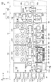
図1は、本発明の一実施の形態に係る基板処理装置の模式的平面図である。
(1) Configuration of Substrate Processing Apparatus FIG. 1 is a schematic plan view of a substrate processing apparatus according to an embodiment of the present invention.
図1および図2以降の所定の図には、位置関係を明確にするために互いに直交するX方向、Y方向およびZ方向を示す矢印を付している。X方向およびY方向は水平面内で互いに直交し、Z方向は鉛直方向に相当する。 1 and 2 and subsequent drawings are provided with arrows indicating X, Y, and Z directions orthogonal to each other in order to clarify the positional relationship. The X direction and the Y direction are orthogonal to each other in the horizontal plane, and the Z direction corresponds to the vertical direction.
図1に示すように、基板処理装置100は、インデクサブロック11、第1の処理ブロック12、第2の処理ブロック13、洗浄乾燥処理ブロック14Aおよび搬入搬出ブロック14Bを備える。洗浄乾燥処理ブロック14Aおよび搬入搬出ブロック14Bにより、インターフェースブロック14が構成される。搬入搬出ブロック14Bに隣接するように露光装置15が配置される。露光装置15においては、液浸法により基板Wに露光処理が行われる。
As shown in FIG. 1, the
図1に示すように、インデクサブロック11は、複数のキャリア載置部111および搬送部112を含む。各キャリア載置部111には、複数の基板Wを多段に収納するキャリア113が載置される。
As shown in FIG. 1, the
搬送部112には、制御部114および搬送機構115が設けられる。制御部114は、基板処理装置100の種々の構成要素を制御する。搬送機構115は、基板Wを保持するためのハンド116を有する。搬送機構115は、ハンド116により基板Wを保持しつつその基板Wを搬送する。
The
搬送部112の側面には、メインパネルPNが設けられる。メインパネルPNは、制御部114に接続されている。使用者は、基板処理装置100における基板Wの処理状況等をメインパネルPNで確認することができる。メインパネルPNの近傍には、例えばキーボードからなる図示しない操作部が設けられている。使用者は、操作部を操作することにより基板処理装置100の動作設定等を行うことができる。
A main panel PN is provided on the side surface of the
第1の処理ブロック12は、塗布処理部121、搬送部122および熱処理部123を含む。熱処理部123は、移動可能に設けられる。基板処理時には、熱処理部123は、搬送部122を挟んで塗布処理部121と対向するように配置される。このときの熱処理部123の位置を定常位置と呼ぶ。一方、基板処理装置100のメンテナンス時には、熱処理部123は、定常位置から離間した位置に配置される。このときの熱処理部123の位置をメンテナンス位置と呼ぶ。これにより、作業スペースを確保することができる。以下の基板処理装置100の説明では、熱処理部123は定常位置に配置されている。
The
搬送部122とインデクサブロック11との間には、基板Wが載置される基板載置部PASS1および後述する基板載置部PASS2〜PASS4(図4参照)が設けられる。搬送部122には、基板Wを搬送する搬送機構127および後述する搬送機構128(図4参照)が設けられる。
Between the
第2の処理ブロック13は、現像処理部131、搬送部132および熱処理部133を含む。熱処理部133は、移動可能に設けられる。基板処理時には、熱処理部133は、搬送部132を挟んで現像処理部131と対向するように配置される。このときの熱処理部133の位置を定常位置と呼ぶ。一方、基板処理装置100のメンテナンス時には、熱処理部133は、定常位置から離間した位置に配置される。このときの熱処理部133の位置をメンテナンス位置と呼ぶ。以下の基板処理装置100の説明では、熱処理部133は定常位置に配置されている。
The
搬送部132と搬送部122との間には、基板Wが載置される基板載置部PASS5および後述する基板載置部PASS6〜PASS8(図4参照)が設けられる。搬送部132には、基板Wを搬送する搬送機構137および後述する搬送機構138(図4参照)が設けられる。
Between the
洗浄乾燥処理ブロック14Aは、洗浄乾燥処理部161,162および搬送部163を含む。洗浄乾燥処理部161,162は、搬送部163を挟んで対向するように設けられる。搬送部163には、搬送機構141,142が設けられる。
The cleaning /
搬送部163と搬送部132との間には、載置兼バッファ部P−BF1および後述の載置兼バッファ部P−BF2(図4参照)が設けられる。載置兼バッファ部P−BF1,P−BF2は、複数の基板Wを収容可能に構成される。
Between the
また、搬送機構141,142の間において、搬入搬出ブロック14Bに隣接するように、基板載置部PASS9および後述の載置兼冷却部P−CP(図4参照)が設けられる。載置兼冷却部P−CPにおいて、基板Wが露光処理に適した温度に冷却される。
A substrate platform PASS9 and a later-described placement / cooling unit P-CP (see FIG. 4) are provided between the
搬入搬出ブロック14Bには、搬送機構146が設けられる。搬送機構146は、露光装置15に対する基板Wの搬入および搬出を行う。露光装置15には、基板Wを搬入するための基板搬入部15aおよび基板Wを搬出するための基板搬出部15bが設けられる。
A
(2)塗布処理部および現像処理部の構成
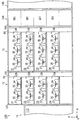
図2は、主として図1の塗布処理部121、現像処理部131および洗浄乾燥処理部161を示す基板処理装置100の模式的側面図である。
(2) Configuration of Application Processing Unit and Development Processing Unit FIG. 2 is a schematic side view of the
図2に示すように、塗布処理部121には、塗布処理室21,22,23,24が階層的に設けられる。現像処理部131には、現像処理室31,32,33,34が階層的に設けられる。塗布処理室21〜24の各々には、塗布処理ユニット129が設けられる。現像処理室31〜34の各々には、現像処理ユニット139が設けられる。
As shown in FIG. 2, the
各塗布処理ユニット129は、基板Wを保持するスピンチャック25およびスピンチャック25の周囲を覆うように設けられるカップ27を備える。本実施の形態では、各塗布処理ユニット129に2組のスピンチャック25およびカップ27が設けられる。スピンチャック25は、図示しない駆動装置(例えば、電動モータ)に着脱可能に設けられる。基板処理時には、スピンチャック25は、駆動装置により回転駆動される。一方、メンテナンス時には、スピンチャック25は、駆動装置から取り外される。また、図1に示すように、各塗布処理ユニット129は、処理液を吐出する複数の処理液ノズル28およびそれらの処理液ノズル28を移動させるノズル搬送機構29を備える。
Each
塗布処理ユニット129においては、図示しない駆動装置によりスピンチャック25が回転されるとともに、複数の処理液ノズル28のうちのいずれかの処理液ノズル28がノズル搬送機構29により基板Wの上方に移動され、その処理液ノズル28から処理液が吐出される。これにより、基板W上に処理液が塗布される。また、図示しないエッジリンスノズルから、基板Wの周縁部にリンス液が吐出される。それにより、基板Wの周縁部に付着する処理液が除去される。
In the
塗布処理室22,24の塗布処理ユニット129においては、反射防止膜用の処理液が処理液ノズル28から基板Wに供給される。塗布処理室21,23の塗布処理ユニット129においては、レジスト膜用の処理液が処理液ノズル28から基板Wに供給される。
In the
現像処理ユニット139は、塗布処理ユニット129と同様に、スピンチャック35およびカップ37を備える。また、図1に示すように、現像処理ユニット139は、現像液を吐出する2つの現像ノズル38およびその現像ノズル38をX方向に移動させる移動機構39を備える。
The
現像処理ユニット139においては、図示しない駆動装置によりスピンチャック35が回転されるとともに、一方の現像ノズル38がX方向に移動しつつ各基板Wに現像液を供給し、その後、他方の現像ノズル38が移動しつつ各基板Wに現像液を供給する。この場合、基板Wに現像液が供給されることにより、基板Wの現像処理が行われる。また、本実施の形態においては、2つの現像ノズル38から互いに異なる現像液が吐出される。それにより、各基板Wに2種類の現像液を供給することができる。
In the
洗浄乾燥処理部161には、複数(本例では4つ)の洗浄乾燥処理ユニットSD1が設けられる。洗浄乾燥処理ユニットSD1においては、露光処理前の基板Wの洗浄および乾燥処理が行われる。
The cleaning /
図1および図2に示すように、塗布処理部121において現像処理部131に隣接するように流体ボックス部50が設けられる。同様に、現像処理部131において洗浄乾燥処理ブロック14Aに隣接するように流体ボックス部60が設けられる。流体ボックス部50および流体ボックス部60内には、塗布処理ユニット129および現像処理ユニット139への薬液の供給ならびに塗布処理ユニット129および現像処理ユニット139からの廃液および排気等に関する流体関連機器が収納される。流体関連機器は、導管、継ぎ手、バルブ、流量計、レギュレータ、ポンプおよび温度調節器等を含む。
As shown in FIGS. 1 and 2, a
(3)熱処理部の構成
図3は、主として図1の熱処理部123,133および洗浄乾燥処理部162を示す基板処理装置100の模式的側面図である。図3に示すように、熱処理部123は、上方に設けられる上段熱処理部301および下方に設けられる下段熱処理部302を有する。上段熱処理部301および下段熱処理部302には、複数の熱処理ユニットPHP、複数の密着強化処理ユニットPAHPおよび複数の冷却ユニットCPが設けられる。
(3) Configuration of Heat Treatment Unit FIG. 3 is a schematic side view of the
熱処理ユニットPHPにおいては、基板Wの加熱処理が行われる。密着強化処理ユニットPAHPにおいては、基板Wと反射防止膜との密着性を向上させるための密着強化処理が行われる。具体的には、密着強化処理ユニットPAHPにおいて、基板WにHMDS(ヘキサメチルジシラサン)等の密着強化剤が塗布されるとともに、基板Wに加熱処理が行われる。冷却ユニットCPにおいては、基板Wの冷却処理が行われる。 In the heat treatment unit PHP, the heat treatment of the substrate W is performed. In the adhesion reinforcement processing unit PAHP, adhesion reinforcement processing for improving the adhesion between the substrate W and the antireflection film is performed. Specifically, in the adhesion reinforcement processing unit PAHP, an adhesion enhancing agent such as HMDS (hexamethyldisilazane) is applied to the substrate W, and the substrate W is subjected to heat treatment. In the cooling unit CP, the substrate W is cooled.
熱処理部133は、上方に設けられる上段熱処理部303および下方に設けられる下段熱処理部304を有する。上段熱処理部303および下段熱処理部304には、冷却ユニットCP、複数の熱処理ユニットPHPおよびエッジ露光部EEWが設けられる。
The
エッジ露光部EEWは、基板Wを水平姿勢で吸着保持して回転するスピンチャック98およびスピンチャック98上に保持された基板Wの外周縁部を露光する光出射器99を備える。スピンチャック98は、図示しない駆動装置(例えば、電動モータ)に着脱可能に設けられる。基板処理時には、スピンチャック98は、駆動装置により回転駆動される。一方、メンテナンス時には、スピンチャック98は、駆動装置から取り外される。
The edge exposure unit EEW includes a
エッジ露光部EEWにおいては、基板W上に形成されたレジスト膜の周縁部の一定幅の領域に露光処理(エッジ露光処理)が行われる。上段熱処理部303および下段熱処理部304において、洗浄乾燥処理ブロック14Aに隣り合うように設けられる熱処理ユニットPHPは、洗浄乾燥処理ブロック14Aからの基板Wの搬入が可能に構成される。
In the edge exposure unit EEW, an exposure process (edge exposure process) is performed on a region having a constant width at the peripheral part of the resist film formed on the substrate W. In the upper
洗浄乾燥処理部162には、複数(本例では5つ)の洗浄乾燥処理ユニットSD2が設けられる。洗浄乾燥処理ユニットSD2においては、露光処理後の基板Wの洗浄および乾燥処理が行われる。
The cleaning /
(4)搬送部の構成
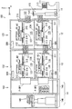
図4は、主として図1の搬送部122,132,163を示す側面図である。図4に示すように、搬送部122は、上段搬送室125および下段搬送室126を有する。搬送部132は、上段搬送室135および下段搬送室136を有する。上段搬送室125には搬送機構127が設けられ、下段搬送室126には搬送機構128が設けられる。また、上段搬送室135には搬送機構137が設けられ、下段搬送室136には搬送機構138が設けられる。
(4) Configuration of Conveying Unit FIG. 4 is a side view mainly showing the conveying
図4に示すように、搬送部112と上段搬送室125との間には、基板載置部PASS1,PASS2が設けられ、搬送部112と下段搬送室126との間には、基板載置部PASS3,PASS4が設けられる。上段搬送室125と上段搬送室135との間には、基板載置部PASS5,PASS6が設けられ、下段搬送室126と下段搬送室136との間には、基板載置部PASS7,PASS8が設けられる。
As shown in FIG. 4, substrate platforms PASS <b> 1 and PASS <b> 2 are provided between the
上段搬送室135と搬送部163との間には、載置兼バッファ部P−BF1が設けられ、下段搬送室136と搬送部163との間には載置兼バッファ部P−BF2が設けられる。搬送部163において搬入搬出ブロック14Bと隣接するように、基板載置部PASS9および複数の載置兼冷却部P−CPが設けられる。
A placement / buffer unit P-BF1 is provided between the
搬送機構127は、基板載置部PASS1,PASS2,PASS5,PASS6、塗布処理室21,22(図2)および上段熱処理部301(図3)の間で基板Wを搬送可能に構成される。搬送機構128は、基板載置部PASS3,PASS4,PASS7,PASS8、塗布処理室23,24(図2)および下段熱処理部302(図3)の間で基板Wを搬送可能に構成される。
The
搬送機構137は、基板載置部PASS5,PASS6、載置兼バッファ部P−BF1、現像処理室31,32(図2)および上段熱処理部303(図3)の間で基板Wを搬送可能に構成される。搬送機構138は、基板載置部PASS7,PASS8、載置兼バッファ部P−BF2、現像処理室33,34(図2)および下段熱処理部304(図3)の間で基板Wを搬送可能に構成される。
The
搬送部122,132には、搬送機構127,128,137,138をそれぞれ制御する複数の制御部500が設けられる。複数の制御部500の一部または全部が図1の制御部114により実現されてもよい。
The
(5)基板処理装置の動作
図1〜図4を参照しながら基板処理装置100の動作を説明する。インデクサブロック11のキャリア載置部111(図1)には、未処理の基板Wが収容されたキャリア113が載置される。搬送機構115は、キャリア113から基板載置部PASS1,PASS3(図4)に未処理の基板Wを搬送する。また、搬送機構115は、基板載置部PASS2,PASS4(図4)に載置された処理済みの基板Wをキャリア113に搬送する。
(5) Operation of Substrate Processing Apparatus The operation of the
第1の処理ブロック12において、搬送機構127(図4)は、基板載置部PASS1に載置された基板Wを密着強化処理ユニットPAHP(図3)、冷却ユニットCP(図3)および塗布処理室22(図2)に順に搬送する。次に、搬送機構127は、塗布処理室22により反射防止膜が形成された基板Wを塗布処理室22(図2)、熱処理ユニットPHP(図3)、冷却ユニットCP(図3)および塗布処理室21(図2)に順に搬送する。続いて、搬送機構127は、塗布処理室21によりレジスト膜が形成された基板Wを、熱処理ユニットPHP(図3)および基板載置部PASS5(図4)に順に搬送する。
In the
この場合、密着強化処理ユニットPAHPにおいて、基板Wに密着強化処理が行われた後、冷却ユニットCPにおいて、反射防止膜の形成に適した温度に基板Wが冷却される。次に、塗布処理室22において、塗布処理ユニット129(図2)により基板W上に反射防止膜が形成される。続いて、熱処理ユニットPHPにおいて、基板Wの熱処理が行われた後、冷却ユニットCPにおいて、レジスト膜の形成に適した温度に基板Wが冷却される。次に、塗布処理室21において、塗布処理ユニット129(図2)により、基板W上にレジスト膜が形成される。その後、熱処理ユニットPHPにおいて、基板Wの熱処理が行われ、その基板Wが基板載置部PASS5に載置される。
In this case, after the adhesion reinforcement processing is performed on the substrate W in the adhesion reinforcement processing unit PAHP, the substrate W is cooled to a temperature suitable for forming the antireflection film in the cooling unit CP. Next, in the
また、搬送機構127は、基板載置部PASS6(図4)に載置された現像処理後の基板Wを基板載置部PASS2(図4)に搬送する。
In addition, the
搬送機構128(図4)は、基板載置部PASS3に載置された基板Wを密着強化処理ユニットPAHP(図3)、冷却ユニットCP(図3)および塗布処理室24に順に搬送する。続いて、搬送機構128は、塗布処理室24により反射防止膜が形成された基板Wを熱処理ユニットPHP(図3)、冷却ユニットCP(図3)および塗布処理室23に順に搬送する。続いて、搬送機構128は、塗布処理室23によりレジスト膜が形成された基板Wを熱処理ユニットPHP(図3)および基板載置部PASS7(図4)に順に搬送する。
The transport mechanism 128 (FIG. 4) sequentially transports the substrate W placed on the substrate platform PASS <b> 3 to the adhesion reinforcement processing unit PAHP (FIG. 3), the cooling unit CP (FIG. 3), and the
また、搬送機構128(図4)は、基板載置部PASS8(図4)に載置された現像処理後の基板Wを基板載置部PASS4(図4)に搬送する。塗布処理室23,24(図2)および下段熱処理部302(図3)における基板Wの処理内容は、上記の塗布処理室21,22(図2)および上段熱処理部301(図3)における基板Wの処理内容と同様である。
Further, the transport mechanism 128 (FIG. 4) transports the substrate W after the development processing placed on the substrate platform PASS8 (FIG. 4) to the substrate platform PASS4 (FIG. 4). The processing contents of the substrate W in the
第2の処理ブロック13において、搬送機構137(図4)は、基板載置部PASS5に載置されたレジスト膜形成後の基板Wをエッジ露光部EEW(図3)および載置兼バッファ部P−BF1(図4)に順に搬送する。この場合、エッジ露光部EEWにおいて、基板Wにエッジ露光処理が行われる。エッジ露光処理後の基板Wが載置兼バッファ部P−BF1に載置される。
In the
また、搬送機構137(図4)は、洗浄乾燥処理ブロック14Aに隣接する熱処理ユニットPHP(図3)から露光処理後でかつ熱処理後の基板Wを取り出す。搬送機構137は、その基板Wを冷却ユニットCP(図3)、現像処理室31,32(図2)のいずれか一方、熱処理ユニットPHP(図3)および基板載置部PASS6(図4)に順に搬送する。
Further, the transport mechanism 137 (FIG. 4) takes out the substrate W after the exposure processing and after the heat treatment from the heat treatment unit PHP (FIG. 3) adjacent to the cleaning /
この場合、冷却ユニットCPにおいて、現像処理に適した温度に基板Wが冷却された後、現像処理室31,32のいずれか一方において、現像処理ユニット139により基板Wの現像処理が行われる。その後、熱処理ユニットPHPにおいて、基板Wの熱処理が行われ、その基板Wが基板載置部PASS6に載置される。
In this case, after the substrate W is cooled to a temperature suitable for the development processing in the cooling unit CP, the development processing of the substrate W is performed by the
搬送機構138(図4)は、基板載置部PASS7に載置されたレジスト膜形成後の基板Wをエッジ露光部EEW(図3)および載置兼バッファ部P−BF2(図4)に順に搬送する。 The transport mechanism 138 (FIG. 4) sequentially transfers the substrate W after the resist film formation placed on the substrate platform PASS7 to the edge exposure unit EEW (FIG. 3) and the placement / buffer unit P-BF2 (FIG. 4). Transport.
また、搬送機構138(図4)は、インターフェースブロック14に隣接する熱処理ユニットPHP(図3)から露光処理後でかつ熱処理後の基板Wを取り出す。搬送機構138は、その基板Wを冷却ユニットCP(図3)、現像処理室33,34(図2)のいずれか一方、熱処理ユニットPHP(図3)および基板載置部PASS8(図4)に順に搬送する。現像処理室33,34および下段熱処理部304における基板Wの処理内容は、上記の現像処理室31,32および上段熱処理部303における基板Wの処理内容と同様である。
Further, the transport mechanism 138 (FIG. 4) takes out the substrate W after the exposure processing and after the heat treatment from the heat treatment unit PHP (FIG. 3) adjacent to the
洗浄乾燥処理ブロック14Aにおいて、搬送機構141(図1)は、載置兼バッファ部P−BF1,P−BF2(図4)に載置された基板Wを洗浄乾燥処理部161の洗浄乾燥処理ユニットSD1(図2)に搬送する。続いて、搬送機構141は、基板Wを洗浄乾燥処理ユニットSD1から載置兼冷却部P−CP(図4)に搬送する。この場合、洗浄乾燥処理ユニットSD1において、基板Wの洗浄および乾燥処理が行われた後、載置兼冷却部P−CPにおいて、露光装置15(図1)における露光処理に適した温度に基板Wが冷却される。
In the cleaning /
搬送機構142(図1)は、基板載置部PASS9(図4)に載置された露光処理後の基板Wを洗浄乾燥処理部162の洗浄乾燥処理ユニットSD2(図3)に搬送する。また、搬送機構142は、洗浄および乾燥処理後の基板Wを洗浄乾燥処理ユニットSD2から上段熱処理部303の熱処理ユニットPHP(図3)または下段熱処理部304の熱処理ユニットPHP(図3)に搬送する。この熱処理ユニットPHPにおいては、露光後ベーク(PEB)処理が行われる。
The transport mechanism 142 (FIG. 1) transports the substrate W after the exposure processing placed on the substrate platform PASS9 (FIG. 4) to the cleaning / drying processing unit SD2 (FIG. 3) of the cleaning /
インターフェースブロック14において、搬送機構146(図1)は、載置兼冷却部P−CP(図4)に載置された露光処理前の基板Wを露光装置15の基板搬入部15a(図1)に搬送する。また、搬送機構146(図1)は、露光装置15の基板搬出部15b(図1)から露光処理後の基板Wを取り出し、その基板Wを基板載置部PASS9(図4)に搬送する。
In the
なお、露光装置15が基板Wの受け入れをできない場合、露光処理前の基板Wが載置兼バッファ部P−BF1,P−BF2に一時的に収容される。また、第2の処理ブロック13の現像処理ユニット139(図2)が露光処理後の基板Wの受け入れをできない場合、露光処理後の基板Wが載置兼バッファ部P−BF1,P−BF2に一時的に収容される。
If the
本実施の形態においては、上段に設けられた塗布処理室21,22、現像処理室31,32および上段熱処理部301,303における基板Wの処理と、下段に設けられた塗布処理室23,24、現像処理室33,34および下段熱処理部302,304における基板Wの処理とを並行して行うことができる。それにより、フットプリントを増加させることなく、スループットを向上させることができる。
In the present embodiment, the processing of the substrate W in the
(6)搬送機構の構成
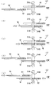
次に、搬送機構127について説明する。図5は、搬送機構127を示す斜視図である。搬送機構128,137,138は搬送機構127と同様の構成を有する。図4および図5に示すように、搬送機構127は、長尺状のガイドレール311,312を備える。図4に示すように、ガイドレール311は、上段搬送室125内において上下方向に延びるように搬送部112側に固定される。ガイドレール312は、上段搬送室125内において上下方向に延びるように上段搬送室135側に固定される。
(6) Configuration of Transport Mechanism Next, the
図4および図5に示すように、ガイドレール311とガイドレール312との間には、長尺状のガイドレール313が設けられる。ガイドレール313は、上下動可能にガイドレール311,312に取り付けられる。ガイドレール313に移動部材314が取り付けられる。移動部材314は、ガイドレール313の長手方向に移動可能に設けられる。
As shown in FIGS. 4 and 5, a
移動部材314の上面には、長尺状の回転部材315が回転可能に設けられる。回転部材315には、基板Wを保持するためのハンドH1およびハンドH2が取り付けられる。本例においては、ハンドH1は、ハンドH2の上方に位置する。ハンドH1,H2は、回転部材315の長手方向に移動可能に設けられる。
A long rotating
上記のような構成により、搬送機構127は、上段搬送室125内においてX方向およびZ方向に移動することができる。また、ハンドH1,H2を用いて塗布処理室21,22(図2)、基板載置部PASS1,PASS2,PASS5,PASS6(図4)および上段熱処理部301(図3)に対して基板Wの受け渡しを行うことができる。
With the configuration as described above, the
また、回転部材315には、センサ装置316が取り付けられる。センサ装置316は、投光部保持ケーシング316aおよび受光部保持ケーシング316bを含む。投光部保持ケーシング316aは回転部材315の上面に配置され、受光部保持ケーシング316bは投光部保持ケーシング316aの上方に配置される。
A
図6(a),(b),(c)は、それぞれ搬送機構127を示す平面図、側面図および端面図である。図6(a)に示すように、ハンドH1は、ガイド部Haおよびアーム部Hbからなる。ガイド部Haは略C字形状を有し、アーム部Hbは長方形状を有する。ガイド部Haの内周部には、ガイド部Haの内周部に沿って形成される円の中心に対して等角度間隔で、ガイド部Haの内側に向かうように複数(本例では3つ)の突出部prが形成されている。各突出部prの先端部に、吸着部smが設けられている。吸着部smは、図示しない吸気系に接続される。
FIGS. 6A, 6 </ b> B, and 6 </ b> C are a plan view, a side view, and an end view showing the
ハンドH1においては、3つの突出部prの3つの吸着部sm上に基板Wが載置される。図6(a)〜(c)においては、ハンドH1により保持される基板Wが二点鎖線で示される。この状態で、3つの吸着部smに接続された吸気系が制御され、3つの吸着部sm上に位置する基板Wの3箇所の部分がそれぞれ3つの吸着部smにより吸着される。なお、ハンドH1は4つの吸着部smを有してもよい。この場合、4つの吸着部sm上に位置する基板Wの4箇所の部分がそれぞれ4つの吸着部smにより吸着される。 In the hand H1, the substrate W is placed on the three suction portions sm of the three protrusions pr. 6A to 6C, the substrate W held by the hand H1 is indicated by a two-dot chain line. In this state, the intake system connected to the three suction portions sm is controlled, and the three portions of the substrate W located on the three suction portions sm are sucked by the three suction portions sm, respectively. The hand H1 may have four suction portions sm. In this case, four portions of the substrate W positioned on the four suction portions sm are sucked by the four suction portions sm, respectively.
複数の吸着部smが基板Wを吸着しているか否かを示す吸着信号が、ハンドH1から図4の制御部500に与えられる。複数の吸着部smが基板Wを吸着している場合には吸着信号はオン状態となり、いずれかの吸着部smが基板Wを吸着していない場合には吸着信号はオフ状態となる。
A suction signal indicating whether or not the plurality of suction parts sm is sucking the substrate W is given from the hand H1 to the
ハンドH2は、ハンドH1と同様の構成を有する。各ハンドH1,H2においては、保持される基板Wの中心が位置すべき正規の位置(以下、正規位置と呼ぶ。)が予め定められている。ハンドH1における正規位置は、例えばガイド部Haの内周部に沿って形成される円の中心位置である。ハンドH1における正規位置は、複数の吸着部smの中心位置であってもよい。 The hand H2 has the same configuration as the hand H1. In each of the hands H1 and H2, a normal position (hereinafter referred to as a normal position) where the center of the substrate W to be held is to be positioned is determined in advance. The normal position in the hand H1 is, for example, the center position of a circle formed along the inner peripheral portion of the guide portion Ha. The normal position in the hand H1 may be the center position of the plurality of suction portions sm.
以下、ハンドH1,H2の進退方向においてハンドH1,H2が後退可能な限界位置を進退基準位置と呼ぶ。図6(a)〜(c)の例では、ハンドH1,H2はそれぞれ進退基準位置にある。 Hereinafter, a limit position where the hands H1 and H2 can move backward in the forward and backward direction of the hands H1 and H2 is referred to as an advance / retreat reference position. In the examples of FIGS. 6A to 6C, the hands H1 and H2 are at the forward / backward reference positions.
回転部材315の上面における略中央部に投光部保持ケーシング316aが設けられる。投光部保持ケーシング316a内では、複数(本例では4つ)の投光部316tが保持されている。投光部保持ケーシング316aに対向するように、回転部材315の上方の位置に受光部保持ケーシング316bが設けられる。受光部保持ケーシング316b内では、投光部保持ケーシング316aにより保持される複数の投光部316tにそれぞれ対向するように複数(本例では4つ)の受光部316rが保持されている。互いに対向する投光部316tおよび受光部316rにより検出器316Dが構成される。図6(c)に示されるように、本例では、センサ装置316は4つの検出器316Dを備える。
A light projecting
4つの検出器316Dは、水平面内において、進退基準位置にあるハンドH1のガイド部Haの内側の領域に配置される。本例では、4つの検出器316Dがガイド部Haの内周部に同心の円弧ar上で一定の間隔をおいて配置される。
The four
4つの投光部316tから上方に向かってそれぞれ光が出射される。4つの受光部316rは、それぞれ対向する4つの投光部316tから出射される光を帰還光として受光することにより受光信号を出力する。各受光部316rから出力された受光信号は、制御部500に与えられる。
Light is emitted upward from each of the four light projecting
4つの投光部316tは、ハンドH1の進退方向において、進退基準位置にあるハンドH1の複数の吸着部smのうち少なくとも1つの吸着部smよりも前方に配置されることが好ましい。この場合、搬送機構127による基板Wの搬送時に、ハンドH1により保持される基板Wの外周部の4つの部分が4つの投光部316tによりそれぞれ確実に検出される。
The four
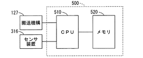
図7は、搬送機構127の制御系の構成を示すブロック図である。他の搬送機構128,137,138の制御系の構成は、図7の搬送機構127の制御系の構成と同様である。
FIG. 7 is a block diagram illustrating a configuration of a control system of the
図7に示すように、制御部500は、CPU(中央演算処理装置)510およびメモリ520を含む。メモリ520には、後述する仮目標位置座標が記憶されるとともに、後述する補正情報が記憶される。CPU510は、搬送機構127のセンサ装置316から与えられる受光信号に基づいて種々の演算を行い、その結果をメモリ520に記憶する。また、メモリ520に記憶された情報に基づいて、搬送機構127の動作を制御する。
As shown in FIG. 7, the
(7)搬送機構に関する教示動作
搬送機構127,128,137,138のハンドH1,H2が基板支持部に移動する際の搬送機構に関する教示動作について説明する。基板処理装置100の設置時に、以下の教示動作が行なわれる。ここで、基板支持部は、例えば、冷却ユニットCP、熱処理ユニットPHPおよび密着強化処理ユニットPAHPの各々に設けられる。また、基板支持部は、例えば、塗布処理ユニット129、現像処理ユニット139およびエッジ露光部EEWの各々に設けられる。
(7) Teaching Operation Related to Transport Mechanism The teaching operation related to the transport mechanism when the hands H1 and H2 of the
教示動作としては、垂直方向の教示動作および水平方向の教示動作がある。以下の説明では、搬送機構127の教示動作を説明する。他の搬送機構128,137,138の教示動作も搬送機構127の教示動作と同様である。
The teaching operation includes a vertical teaching operation and a horizontal teaching operation. In the following description, the teaching operation of the
基板支持部により支持された基板Wの高さを基準高さと呼ぶ。搬送機構127のハンドH1が基板支持部に基板Wを渡し、または基板支持部から基板Wを受け取るためにハンドH1が基板支持部WSの下方に移動したときのハンドH1の高さ目標高さと呼ぶ。垂直方向の教示動作により目標高さが決定される。
The height of the substrate W supported by the substrate support unit is referred to as a reference height. The hand H1 of the
また、基板支持部により基板Wが支持されるべき位置を基準位置と呼ぶ。水平方向の教示動作の前に搬送機構127のハンドH1により基板支持部に渡された基板Wの位置を仮目標位置と呼ぶ。水平方向の教示動作により基準位置と仮目標位置とのずれを示す補正情報が取得される。補正情報に基づいて仮目標位置が基準位置と一致するように仮目標位置が補正される。補正後の仮目標位置を真目標位置と呼ぶ。
A position where the substrate W is to be supported by the substrate support portion is referred to as a reference position. The position of the substrate W transferred to the substrate support portion by the hand H1 of the
基板支持部が冷却ユニットCP、熱処理ユニットPHPまたは密着強化処理ユニットPAHPである場合、基板Wは、その中心が基準位置と一致するように基板支持部の案内機構により自動的に案内される。一方、基板支持部がスピンチャック25,35,98である場合、基板Wは、その中心が基準位置と一致するとは限らない。 When the substrate support portion is the cooling unit CP, the heat treatment unit PHP, or the adhesion reinforcement processing unit PAHP, the substrate W is automatically guided by the guide mechanism of the substrate support portion so that the center thereof coincides with the reference position. On the other hand, when the substrate support portions are the spin chucks 25, 35, and 98, the center of the substrate W does not always coincide with the reference position.
以下の説明では、X方向、Y方向およびZ方向の位置をそれぞれX座標、Y座標およびZ座標で表わす。 In the following description, the positions in the X direction, the Y direction, and the Z direction are represented by the X coordinate, the Y coordinate, and the Z coordinate, respectively.
図8は、垂直方向の教示動作を説明するための図である。図8(a)〜(d)は、基板支持部WSおよび搬送機構127のハンドH1の略中央部の縦断面図を示す。図8(a)〜(d)の例では、搬送機構127のハンドH1が基板支持部WSの下方に移動する場合の目標高さが決定される。
FIG. 8 is a diagram for explaining the teaching operation in the vertical direction. 8A to 8D are longitudinal sectional views of the substrate support part WS and the substantially central part of the hand H1 of the
まず、図8(a)に示すように、基板支持部WSにより基板Wが基準高さで支持される。次に、図8(b)に示すように、制御部500は、ハンドH1を進退基準位置から基板支持部WSの下方の位置まで水平方向に移動させる。この時点では、ハンドH1の複数の吸着部smには基板Wが吸着されていない。そのため、吸着信号はオフ状態である。搬送機構127は、エンコーダを有する。制御部500は、搬送機構127のエンコーダの出力信号に基づいてハンドH1の位置を常時検出している。
First, as shown in FIG. 8A, the substrate W is supported at the reference height by the substrate support portion WS. Next, as illustrated in FIG. 8B, the
続いて、制御部500は、ハンドH1を上方に移動させる。この場合、図8(c)に示すように、ハンドH1が上方に所定の距離だけ移動した時点で、複数の吸着部smが基板Wを吸着する。これにより、吸着信号がオン状態になる。制御部500は、吸着信号がオン状態になった時点のハンドH1のZ座標を基準高さのZ座標として決定する。また、制御部500は、基準高さのZ座標に垂直方向の所定のオフセット量を加算した座標を目標高さのZ座標として決定する。
Subsequently, the
以下、基準高さのZ座標を基準高さ座標と呼び、目標高さのZ座標を目標高さ座標と呼ぶ。目標高さ座標および目標高さ座標から基準高さ座標までのオフセット量は、制御部500のメモリ520に記憶される。その後、図8(d)に示すように、制御部500は、ハンドH1を基板支持部WSの上方まで移動させた後、進退基準位置まで水平方向に移動させる。
Hereinafter, the Z coordinate of the reference height is referred to as the reference height coordinate, and the Z coordinate of the target height is referred to as the target height coordinate. The target height coordinate and the offset amount from the target height coordinate to the reference height coordinate are stored in the
図9は、水平方向の教示動作を説明するための図である。図9(a)〜(c)は、基板支持部WSおよび搬送機構127のハンドH1の平面図を示す。図9(a)〜(c)の例では、搬送機構127のハンドH1を用いて基板支持部WSについての補正情報を取得する。
FIG. 9 is a diagram for explaining the teaching operation in the horizontal direction. 9A to 9C are plan views of the substrate support part WS and the hand H1 of the
まず、図9(a)に示すように、基板支持部WSに基板Wが支持される。ここで、基板Wは、その中心が基準位置に正確に一致する状態で支持される。一方、水平方向の教示動作の前においては、制御部500は基板支持部WSの基準位置を認識していない。そのため、仮目標位置は基準位置と一致するとは限らない。
First, as shown in FIG. 9A, the substrate W is supported by the substrate support portion WS. Here, the substrate W is supported in a state where the center thereof exactly matches the reference position. On the other hand, before the teaching operation in the horizontal direction, the
以下、基準位置の座標を基準位置座標と呼び、仮目標位置の座標を仮目標位置座標と呼ぶ。また、ハンドH1上での正規位置の座標を正規位置座標と呼ぶ。基準位置座標は(Xw,Yw)であり、仮目標位置座標は(Xb,Yb)であり、正規位置座標は(Xr,Yr)である。仮目標位置座標は、制御部500のメモリ520に記憶されている。図9(a)の例では、基準位置座標(Xw,Yw)と仮目標位置座標(Xb,Yb)とは一致していない。
Hereinafter, the coordinates of the reference position are referred to as reference position coordinates, and the coordinates of the temporary target position are referred to as temporary target position coordinates. Further, the coordinates of the normal position on the hand H1 are referred to as normal position coordinates. The reference position coordinates are (Xw, Yw), the temporary target position coordinates are (Xb, Yb), and the normal position coordinates are (Xr, Yr). The temporary target position coordinates are stored in the
図9(a)の状態で、制御部500は、図示しない複数のリフトピンを基板支持部WSの下方から上方に上昇させることにより、基板Wを基板支持部WSの上方に上昇させる。次に、ハンドH1の正規位置が仮目標位置と一致するようにハンドH1を進退基準位置から水平方向に移動させる。この時点で、ハンドH1は基板支持部WSの上方でかつ基板Wの下方に位置する。
In the state of FIG. 9A, the
続いて、制御部500は、図示しない複数のリフトピン下降させることにより、基板Wを下降させる。これにより、図9(b)に示すように、基板WがハンドH1の複数の吸着部smに吸着される。この場合、基板Wは、その中心が正規位置からずれた状態でハンドH1により保持される。
Subsequently, the
その後、図9(c)に示すように、制御部500は、ハンドH1を進退基準位置まで水平方向に移動させる。ここで、図5および図6の回転部材315上でハンドH1がセンサ装置316よりも前方の位置から進退基準位置まで後退することによりハンドH1に保持された基板Wの外周部の複数の部分がそれぞれ検出される。ハンドH1に保持された基板Wの外周部の検出方法についての詳細は後述する。
Thereafter, as shown in FIG. 9C, the
制御部500は、基板Wの外周部の複数の部分の検出結果に基づいて、ハンドH1における基板Wの中心の位置(以下、検出位置と呼ぶ)を検出する。以下、検出位置の座標を検出位置座標と呼ぶ。検出位置座標は(Xwh,Ywh)である。次に、下記式(1),(2)に基づいて、X方向およびY方向における仮目標位置座標に対する基準位置座標のずれ(ΔX,ΔY)を補正情報として算出する。
The
ΔX=Xr−Xwh (1)
ΔY=Yr−Ywh (2)
続いて、制御部500は、下記式(3),(4)に基づいて、真目標位置の座標(以下、真目標位置座標と呼ぶ。)を算出する。真目標位置座標は(Xrb,Yrb)である。真目標位置座標は(Xrb,Yrb)は、制御部500のメモリ520に記憶される。
ΔX = Xr−Xwh (1)
ΔY = Yr−Ywh (2)
Subsequently, the
Xrb=Xb−ΔX (3)
Yrb=Yb−ΔY (4)
これにより、真目標位置座標(Xrb,Yrb)は基準位置座標(Xw,Yw)と一致する。
Xrb = Xb−ΔX (3)
Yrb = Yb−ΔY (4)
Thereby, the true target position coordinates (Xrb, Yrb) coincide with the reference position coordinates (Xw, Yw).
基板Wの処理時には、制御部500は、ハンドH1が真目標位置に移動するように搬送機構127を制御する。その結果、基板Wの中心が基板支持部WSの基準位置と一致するようにハンドH1により基板Wが基板支持部WSに渡される。また、ハンドH1の正規位置に基板Wが保持されるようにハンドH1により基板支持部WSから基板Wが受け取られる。
When processing the substrate W, the
上記の例では、搬送機構127のハンドH1を用いた教示動作について説明したが、ハンドH2を用いた教示動作も、ハンドH1を用いた教示動作と同様である。また、搬送機構128,137,138は、搬送機構127と同様の構成および動作を有する。そのため、搬送機構128,137,138を用いた教示動作も、搬送機構127を用いた教示動作と同様である。
In the above example, the teaching operation using the hand H1 of the
(8)基板の外周部の検出方法
図10は、図5および図6のセンサ装置316による基板Wの外周部の複数の部分の検出方法を説明するための図である。図10(a),(c),(e),(g)に、ハンドH1が進退基準位置に向かって後退する場合のハンドH1、回転部材315および複数の検出器316Dの状態の変化が平面図で示される。図10(b),(d),(f),(h)に、図10(a),(c),(e),(g)のQ−Q線における模式的断面図がそれぞれ示される。なお、ハンドH2についての説明は省略する。
(8) Method for Detecting Outer Periphery of Substrate FIG. 10 is a diagram for explaining a method for detecting a plurality of portions of the outer periphery of the substrate W by the
初めに、ハンドH1により基板Wが受け取られるタイミングでは、ハンドH1が4つの検出器316Dよりも前方に位置する。この場合、ハンドH1は4つの投光部316tと4つの受光部316rとの間に位置しない。したがって、4つの受光部316rはそれぞれ対向する4つの投光部316tからの光を受光する。それにより、制御部500に受光信号が与えられる。
First, at the timing when the substrate W is received by the hand H1, the hand H1 is positioned in front of the four
次に、ハンドH1が後退する。この場合、図10(a),(b)に示すように、ハンドH1が4つの投光部316tと4つの受光部316rとの間の空間に進入する。このとき、4つの投光部316tから出射される光がハンドH1により遮られるので、4つの受光部316rはそれぞれ対向する4つの投光部316tからの光を受光しない。したがって、制御部500に受光信号は与えられない。
Next, the hand H1 moves backward. In this case, as shown in FIGS. 10A and 10B, the hand H1 enters the space between the four light projecting
次に、図10(c),(d)に示すように、ハンドH1が4つの投光部316tと4つの受光部316rとの間の空間を通過する。ハンドH1が各投光部316tとその投光部316tに対向する受光部316rとの間の空間を通過するタイミングで、各受光部316rは対向する投光部316tからの光を受光する。それにより、制御部500に受光信号が与えられる。
Next, as shown in FIGS. 10C and 10D, the hand H1 passes through the space between the four light projecting
次に、図10(e),(f)に示すように、ハンドH1により保持される基板Wが4つの投光部316tと4つの受光部316rとの間の空間に進入する。ハンドH1により保持される基板Wの外周部が各投光部316tとその投光部316tに対向する受光部316rとの間の空間に進入するタイミングで、各投光部316tから出射される光が基板Wの外周部により遮られる。この場合、各受光部316rは対向する投光部316tからの光を受光しない。したがって、制御部500に受光信号は与えられない。
Next, as shown in FIGS. 10E and 10F, the substrate W held by the hand H1 enters the space between the four light projecting
次に、図10(g),(h)に示すように、ハンドH1が進退基準位置で停止する。このとき、ハンドH1により保持される基板Wが4つの投光部316tと4つの受光部316rとの間の空間に位置する。この場合、4つの受光部316rはそれぞれ対向する4つの投光部316tからの光を受光しない。したがって、制御部500に受光信号は与えられない。
Next, as shown in FIGS. 10G and 10H, the hand H1 stops at the advance / retreat reference position. At this time, the substrate W held by the hand H1 is positioned in a space between the four light projecting
上記のように、ハンドH1により基板Wが受け取られた後、ハンドH1が進退基準位置に移動するまでの間に、制御部500には4つの検出器316Dの4つの受光部316rからそれぞれ断続的に受光信号が与えられる。
As described above, after the substrate W is received by the hand H1 and before the hand H1 moves to the advance / retreat reference position, the
制御部500は、基板Wの外周部により4つの受光部316rの各々から受光信号が与えられなくなるタイミング(図10(e),(f)のタイミング)に基づいて、基板Wの外周部の4つの部分が検出される。ここで、制御部500のメモリ520には、正規データが予め記憶されている。正規データは、基板Wの中心がハンドH1の正規位置にある状態で、ハンドH1がセンサ装置316の前方の位置から進退基準位置に移動したときに得られる基板Wの外周部の4つの部分の検出結果を示すデータである。
Based on the timing at which the light receiving signal is not given from each of the four
センサ装置316は回転部材315に対して固定されている。したがって、センサ装置316の複数の検出器316Dの座標上の位置は変化しない。そこで、制御部500は、基板Wの外周部の4つの部分の検出結果と正規データの4つの部分の検出結果との差分に基づいて、ハンドH1が進退基準位置にあるときの基板Wの外周部の4つの部分の位置を示す座標を算出する。算出された4つの部分の位置の座標に基づいて、ハンドH1が進退基準位置にあるときの基板Wの中心の位置の座標が算出される。
The
ハンドH1における基板Wの中心の位置の座標は、基板Wの外周部の3つの部分の座標に基づいて算出することができる。本例では、基板Wの外周部の4つの部分の座標が得られる。それにより、例えば4つの部分のうちの1つの部分が基板Wの位置決め用の切り欠き(オリエンテーションフラットまたはノッチ)部分であった場合でも、切り欠き部分の座標を除く3つの部分の座標に基づいて基板Wの中心の位置の座標を算出することができる。基板Wの外径が既知である場合には、基板Wの外周部の2つの部分の座標に基づいて基板Wの中心の位置の座標を算出することが可能である。この場合、センサ装置316は、2つまたは3つの検出器316Dにより構成されてもよい。
The coordinates of the center position of the substrate W in the hand H1 can be calculated based on the coordinates of the three portions of the outer peripheral portion of the substrate W. In this example, the coordinates of four portions of the outer peripheral portion of the substrate W are obtained. Thereby, for example, even when one of the four parts is a notch (orientation flat or notch) part for positioning the substrate W, it is based on the coordinates of the three parts excluding the coordinates of the notch part. The coordinates of the center position of the substrate W can be calculated. When the outer diameter of the substrate W is known, the coordinates of the center position of the substrate W can be calculated based on the coordinates of the two portions of the outer peripheral portion of the substrate W. In this case, the
(9)基板支持部の基準位置
上記のように、教示動作においては、基板支持部WSが冷却ユニットCP、熱処理ユニットPHPまたは密着強化処理ユニットPAHPである場合、基板Wは、その中心が基板支持部WSの基準位置に正確に一致する状態で支持される。以下、基板支持部WSの基準位置を説明する。
(9) Reference position of substrate support portion As described above, in the teaching operation, when the substrate support portion WS is the cooling unit CP, the heat treatment unit PHP, or the adhesion reinforcement processing unit PAHP, the center of the substrate W is the substrate support. It is supported in a state where it exactly matches the reference position of the part WS. Hereinafter, the reference position of the substrate support part WS will be described.
図11は、熱処理ユニットPHPの斜視図である。図12は、図11の熱処理ユニットPHPの平面図である。図13は、図11の熱処理ユニットPHPの側面図である。図11および図12に示すように、熱処理ユニットPHPは、冷却部410、加熱部420および搬送機構430を含む。冷却部410および加熱部420は、並ぶように配置されている。搬送機構430は、冷却部410と加熱部420との間で基板Wを搬送可能に配置される。
FIG. 11 is a perspective view of the heat treatment unit PHP. FIG. 12 is a plan view of the heat treatment unit PHP of FIG. FIG. 13 is a side view of the heat treatment unit PHP of FIG. As shown in FIGS. 11 and 12, the heat treatment unit PHP includes a
冷却部410は、基板載置プレート411および昇降可能な複数(本例では3つ)の支持ピン412を含む。基板載置プレート411は、例えばクーリングプレートである。基板載置プレート411には、複数(本例では3つ)の支持ピン挿入孔が形成されている。後述する搬送機構430の搬送アーム434が基板載置プレート411の上面に接触することにより、搬送アーム434により保持される基板Wを搬送アーム434とともに冷却することができる。
The
複数の支持ピン412は、上下方向に移動することにより基板載置プレート411の複数の支持ピン挿入孔にそれぞれ挿入可能に配置される。冷却部410への基板Wの搬入時および搬出時には、複数の支持ピン412の上端部がそれぞれ複数の支持ピン挿入孔を通して基板載置プレート411の上方の位置と基板載置プレート411の上面よりも下方の位置との間で移動する。
The plurality of support pins 412 are arranged so as to be respectively inserted into the plurality of support pin insertion holes of the
加熱部420は、基板載置プレート421、昇降可能な複数(本例では3つ)の支持ピン422および複数(本例では6つ)のガイド部材423を含む。基板載置プレート421は、例えば基板Wに加熱処理を行うホットプレートである。基板載置プレート421には、複数(本例では3つ)の支持ピン挿入孔が形成されている。複数の支持ピン422は、複数の支持ピン412と同様の構成を有する。
The
複数のガイド部材423は、基板載置プレート421の縁に沿って略等間隔で設けられる。本例では、6個のガイド部材423が略60°間隔で設けられる。図13に示すように、各ガイド部材423は円錐台形状を有する。複数のガイド部材423により囲まれる領域に基板Wが配置される場合、ガイド部材423の傾斜した側面に沿って基板Wが下方に導かれる。これにより、基板載置プレート421の中心と基板Wの中心とが一致する。
The plurality of
搬送機構430は、上下方向に延びるように設けられた2本の長尺状のガイドレール431,432を備える。ガイドレール431,432は、冷却部410および加熱部420を挟んで対向するように配置される。ガイドレール431とガイドレール432との間には、長尺状のガイドレール433が設けられる。ガイドレール433は、上下動可能にガイドレール431,432に取り付けられる。ガイドレール433に搬送アーム434が取り付けられる。搬送アーム434は、ガイドレール433の長手方向に移動可能に設けられる。
The
図13に示すように、搬送アーム434には、冷却部410の複数の支持ピン412および加熱部420の複数の支持ピン422と干渉しないように切り込み(スリット)435が設けられている。また、搬送アーム434には、複数のガイド部材436が設けられる。複数のガイド部材436は、複数のガイド部材423と同様の構成を有する。基板処理時には、搬送アーム434は、冷却部410と加熱部420との間で基板Wを搬送する。本例では、搬送アーム434が基板支持部WSであり、複数のガイド部材436が案内機構である。
As shown in FIG. 13, the
図14は、基板支持部WSが熱処理ユニットPHPに設けられる場合における基準位置を説明するための図である。以下、熱処理ユニットPHPの搬送アーム434が基板支持部WSである場合における基準位置を説明する。冷却ユニットCPおよび密着強化処理ユニットPAHPにおける基準位置は、熱処理ユニットPHPにおける基準位置と同様である。
FIG. 14 is a view for explaining a reference position when the substrate support part WS is provided in the heat treatment unit PHP. Hereinafter, the reference position when the
教示動作時には、まず、図14(a)に示すように、冷却部410の複数の支持ピン412が上昇する。次に、図14(b)に示すように、搬送機構127はハンドH1により基板Wを保持し、上昇した複数の支持ピン412の上端に搬送する。これにより、基板Wは、その中心が仮目標位置にある状態で、複数の支持ピン412により支持される。
During the teaching operation, first, as shown in FIG. 14A, the plurality of support pins 412 of the
その後、図14(c)に示すように、複数の支持ピン412が下降する。ここで、仮目標位置と基準位置とが一致していない場合、図14(c)に矢印で示すように、搬送アーム434上の複数のガイド部材436の傾斜した側面に沿って、基板Wが下方に導かれる。これにより、搬送アーム434の中心と基板Wの中心とが一致する。
Thereafter, as shown in FIG. 14C, the plurality of support pins 412 descend. Here, when the temporary target position and the reference position do not coincide with each other, the substrate W moves along the inclined side surfaces of the plurality of
次に、図14(d)に示すように、複数の支持ピン412が上昇する。続いて、図14(e)に示すように、搬送機構127はハンドH1により複数の支持ピン412から基板Wを受け取る。図14(d)において、複数の支持ピン412により支持された基板Wの中心の位置が基準位置となる。すなわち、複数のガイド部材436により導かれた基板Wの中心の位置が基準位置となる。
Next, as shown in FIG.14 (d), the some
(10)スピンチャックにおける教示動作
スピンチャック25,35,98が基板支持部WSである場合において、スピンチャック25,35,98の回転中心の位置が既知である場合には、回転中心の位置を基準位置として水平方向の教示動作が行われてもよい。一方で、スピンチャック25,35,98の回転中心の位置が未知である場合には、以下の手順により水平方向の教示動作が行われてもよい。
(10) Teaching operation in the spin chuck When the spin chucks 25, 35, and 98 are the substrate support parts WS and the positions of the rotation centers of the spin chucks 25, 35, and 98 are known, the position of the rotation center is set. A horizontal teaching operation may be performed as a reference position. On the other hand, when the position of the rotation center of the spin chucks 25, 35, 98 is unknown, a horizontal teaching operation may be performed by the following procedure.
図15は、スピンチャック25,35,98が基板支持部WSである場合における水平方向の教示動作を説明するための図である。図15(a)〜(d)は、搬送機構127およびスピンチャック25の模式的平面図を示す。図15の例においては、基板支持部WSはスピンチャック25である。スピンチャック35,98における教示動作は、スピンチャック25における教示動作と同様である。
FIG. 15 is a diagram for explaining the horizontal teaching operation in the case where the spin chucks 25, 35, 98 are the substrate support parts WS. FIGS. 15A to 15D are schematic plan views of the
まず、図15(a)に示すように、搬送機構127はハンドH1により正規位置に基板Wを保持する。ここで、基板Wの中心の座標を算出する。算出された基板Wの中心の座標は(X1,Y1)である。次に、図15(b)に示すように、搬送機構127は基板Wをスピンチャック25に搬送する。スピンチャック25は、基板Wの中心が仮目標位置に一致するように基板Wを保持する。続いて、図15(c)に示すように、スピンチャック25は、基板Wを所定の角度だけ回転させる。スピンチャック25による基板Wの回転角度は180°であることが好ましい。
First, as shown in FIG. 15A, the
その後、図15(d)に示すように、搬送機構127は、基板Wをスピンチャック25から受け取る。ここで、基板Wの中心の座標を算出する。算出された基板Wの中心の座標は(X2,Y2)である。次に、算出された座標(X1,Y1)および座標(X2,Y2)に基づいて、仮目標位置座標に対する基準位置座標のずれ(ΔX,ΔY)を算出する。ここで、図15(b),(c)の処理において、基板Wの回転角度が180°であった場合には、仮目標位置座標に対する基準位置座標のずれ(ΔX,ΔY)は下記式(5),(6)により与えられる。
Thereafter, as shown in FIG. 15D, the
ΔX=(X1+X2)/2 (5)
ΔY=(Y1+Y2)/2 (6)
続いて、真目標位置座標(Xrb,Yrb)を算出する。X方向における真目標位置Xrbは、下記式(7)で与えられる。ここで、X1<X2である場合には正号が適用され、X1>X2である場合には負号が適用される。また、Y方向における真目標位置Yrbは、下記式(8)で与えられる。ここで、Y1<Y2である場合には正号が適用され、Y1>Y2である場合には負号が適用される。算出された真目標位置座標(Xrb,Yrb)は、補正情報として制御部500のメモリ520に記憶される。
ΔX = (X1 + X2) / 2 (5)
ΔY = (Y1 + Y2) / 2 (6)
Subsequently, true target position coordinates (Xrb, Yrb) are calculated. The true target position Xrb in the X direction is given by the following equation (7). Here, a positive sign is applied when X1 <X2, and a negative sign is applied when X1> X2. The true target position Yrb in the Y direction is given by the following formula (8). Here, a positive sign is applied when Y1 <Y2, and a negative sign is applied when Y1> Y2. The calculated true target position coordinates (Xrb, Yrb) are stored in the
Xrb=Xb±ΔX (7)
Yrb=Yb±ΔY (8)
上記の例では、搬送機構127のハンドH1を用いた教示動作について説明したが、ハンドH2を用いた教示動作も、ハンドH1を用いた動作と同様である。また、搬送機構128,137,138を用いた教示動作も、搬送機構127を用いた教示動作と同様である。
Xrb = Xb ± ΔX (7)
Yrb = Yb ± ΔY (8)
In the above example, the teaching operation using the hand H1 of the
(11)位置ずれ検出動作
(a)水平方向の位置ずれ検出動作
教示動作が行なわれた後でかつ基板処理装置100のメンテナンスが行なわれた後には、基板支持部WSの位置ずれ検出動作が行なわれる。位置ずれ検出動作は、水平方向の位置ずれ検出動作と垂直方向の位置ずれ検出動作とを含む。
(11) Misalignment detection operation (a) Horizontal misalignment detection operation After the teaching operation is performed and the
図16は、基板支持部WSがスピンチャックに設けられる場合における水平方向の位置ずれ検出動作を説明するための図である。図16(a)〜(d)は、搬送機構127およびスピンチャック25の模式的平面図を示す。図16の例においては、基板支持部WSはスピンチャック25である。スピンチャック35,98における位置ずれ検出動作は、スピンチャック25における位置ずれ検出動作と同様である。
FIG. 16 is a diagram for explaining the horizontal position shift detection operation when the substrate support part WS is provided in the spin chuck. FIGS. 16A to 16D are schematic plan views of the
基板処理時には、メモリ520に記憶された補正情報に基づいてハンドH1が真目標位置に移動されることにより、ハンドH1により基板支持部WSに基板Wが渡され、または基板支持部WSから基板Wが受け取られる。それにより、基準位置で基板Wが支持されるようにハンドH1により基板Wを基板支持部WSに渡すことができ、または基準位置で支持された基板Wを受け取るようにハンドH1を基板支持部WSに移動させることができる。
At the time of substrate processing, the hand H1 is moved to the true target position based on the correction information stored in the
基板処理装置100のメンテナンスが行なわれた後には、メンテナンス時に取り外されていたスピンチャック25が図示しない駆動装置に取り付けられる。ここで、図16(a)に示すように、スピンチャック25が、その基準位置がずれた状態で駆動装置に取り付けられる可能性がある。図16(a)においては、取り外される前におけるスピンチャック25が一点鎖線で示されている。
After the maintenance of the
この場合には、図16(b)に示すように、正規位置で基板Wを保持したハンドH1を真目標位置に移動させても、基準位置で基板Wが支持されるように基板Wをスピンチャック25に渡すことができなくなる。同様に、ハンドH1を真目標位置に移動させても、スピンチャック25の基準位置で支持された基板WをハンドH1の正規位置で受け取ることができなくなる。
In this case, as shown in FIG. 16B, the substrate W is spun so that the substrate W is supported at the reference position even if the hand H1 holding the substrate W at the normal position is moved to the true target position. It cannot be passed to the
そこで、位置ずれ検出動作時には、図16(c)に示すように、スピンチャック25は、支持した基板Wを所定の角度だけ回転させる。スピンチャック25による基板Wの回転角度は180°であることが好ましい。その後、図16(d)に示すように、ハンドH1は、その正規位置を真目標位置に移動させて、基板Wをスピンチャック25から受け取る。ここで、基板Wの中心の座標を算出する。算出された基板Wの中心の座標は(x1,y1)である。
Therefore, at the time of misalignment detection operation, as shown in FIG. 16C, the
正規位置の座標(X1,Y1)と算出された座標(x1,y1)との中点から正規位置の座標(X1,Y1)までの距離は、基準位置座標(Xw,Yw)から真目標位置座標(Xrb,Yrb)までの距離に等しい。ここで、正規位置の座標(X1,Y1)と算出された座標(x1,y1)とのずれ量が予め定められたしきい値よりも大きい場合には、警報が出力される。これにより、スピンチャック25に位置ずれが生じたことが作業者に通知される。
The distance from the midpoint between the coordinates (X1, Y1) of the normal position and the calculated coordinates (x1, y1) to the coordinates (X1, Y1) of the normal position is the true target position from the reference position coordinates (Xw, Yw). It is equal to the distance to the coordinates (Xrb, Yrb). Here, if the deviation between the coordinates (X1, Y1) of the normal position and the calculated coordinates (x1, y1) is larger than a predetermined threshold value, an alarm is output. As a result, the operator is notified that a positional shift has occurred in the
警報の出力は、例えば音声であってもよいし、ブザー等による警報音の発生であってもよいし、ランプ等による警報表示であってもよい。あるいは、警報の出力は、画面上での文字または図形の表示であってもよい。 The output of the alarm may be, for example, sound, generation of an alarm sound by a buzzer or the like, or alarm display by a lamp or the like. Alternatively, the alarm output may be a character or graphic display on the screen.
図17は、基板支持部WSが熱処理ユニットPHPに設けられる場合における水平方向の位置ずれ検出動作を説明するための図である。図17(a)〜(d)は、搬送機構127および熱処理ユニットPHPの一部の模式的平面図を示す。冷却ユニットCPおよび密着強化処理ユニットPAHPにおける位置ずれ検出動作は、熱処理ユニットPHPにおける位置ずれ検出動作と同様である。
FIG. 17 is a diagram for explaining a horizontal displacement detection operation when the substrate support WS is provided in the heat treatment unit PHP. FIGS. 17A to 17D are schematic plan views of a part of the
基板処理装置100のメンテナンスが行なわれた後には、熱処理部123,133(図3参照)がメンテナンス位置から定常位置に移動される。ここで、熱処理部123,133が定常位置からずれた位置に移動される可能性がある。図17(a)においては、熱処理部が定常位置にある場合における熱処理ユニットPHPが一点鎖線で示されている。
After the maintenance of the
この場合には、図17(b)に示すように、正規位置で基板Wを保持したハンドH1を真目標位置に移動させても、基準位置で基板Wが支持されるように基板Wを熱処理ユニットPHPに渡すことができなくなる。同様に、ハンドH1を真目標位置に移動させても、熱処理ユニットPHPの基準位置で支持された基板WをハンドH1の正規位置で受け取ることができなくなる。 In this case, as shown in FIG. 17B, the substrate W is heat-treated so that the substrate W is supported at the reference position even if the hand H1 holding the substrate W at the normal position is moved to the true target position. Cannot be passed to unit PHP. Similarly, even if the hand H1 is moved to the true target position, the substrate W supported at the reference position of the heat treatment unit PHP cannot be received at the regular position of the hand H1.
そこで、位置ずれ検出動作時には、図17(c)に示すように、熱処理ユニットPHPの基準位置で支持された基板Wを準備する。その後、図17(d)に示すように、ハンドH1は、その正規位置を真目標位置に移動させて、基板Wを熱処理ユニットPHPから受け取る。ここで、基板Wの中心の座標を算出する。算出された基板Wの中心の座標は(x1,y1)である。 Therefore, during the positional deviation detection operation, as shown in FIG. 17C, the substrate W supported at the reference position of the heat treatment unit PHP is prepared. Thereafter, as shown in FIG. 17D, the hand H1 moves its normal position to the true target position, and receives the substrate W from the thermal processing unit PHP. Here, the coordinates of the center of the substrate W are calculated. The coordinates of the calculated center of the substrate W are (x1, y1).
正規位置の座標(X1,Y1)から算出された座標(x1,y1)までの距離は、基準位置座標(Xw,Yw)から真目標位置座標(Xrb,Yrb)までの距離に等しい。ここで、正規位置の座標(X1,Y1)と算出された座標(x1,y1)とのずれ量が予め定められたしきい値よりも大きい場合には、警報が出力される。これにより、熱処理ユニットPHPに位置ずれが生じたことが作業者に通知される。 The distance from the coordinates (X1, Y1) of the normal position to the calculated coordinates (x1, y1) is equal to the distance from the reference position coordinates (Xw, Yw) to the true target position coordinates (Xrb, Yrb). Here, if the deviation between the coordinates (X1, Y1) of the normal position and the calculated coordinates (x1, y1) is larger than a predetermined threshold value, an alarm is output. As a result, the operator is notified that a positional shift has occurred in the heat treatment unit PHP.
(b)垂直方向の位置ずれ検出動作
図18は、垂直方向の位置ずれ検出動作を説明するための図である。図18(a)〜(d)は、搬送機構127および基板支持部WSの模式的断面図を示す。
(B) Vertical Position Detection Operation FIG. 18 is a diagram for explaining the vertical position detection operation. 18A to 18D are schematic cross-sectional views of the
メモリ520に記憶された目標高さ座標に基づいてハンドH1が目標高さに移動されることにより、基板支持部WSに基板Wが渡され、または基板支持部WSから基板Wが受け取られる。それにより、基準高さで基板Wが支持されるようにハンドH1により基板Wを基板支持部WSに渡すことができ、または基準高さで支持された基板Wを受け取るようにハンドH1を基板支持部WSに移動させることができる。図18(a)の例においては、目標高さにあるハンドH1の吸着部smの吸着面ssと基板支持部WSにより基準高さで支持される基板Wの下面との距離はZ1である。
When the hand H1 is moved to the target height based on the target height coordinates stored in the
しかしながら、吸着部smは、基板Wを繰り返し吸着することにより、徐々に磨耗する。したがって、吸着部smを長期間にわたって使用した場合、図18(b)に示すように、吸着部smの高さ方向の寸法が減少する。図18(b)の例においては、目標高さにあるハンドH1の吸着部smの吸着面ssと基板支持部WSにより基準高さで支持される基板Wの下面との距離はZ2である。距離Z2は距離Z1よりも大きい。 However, the adsorption part sm is gradually worn out by repeatedly adsorbing the substrate W. Therefore, when the suction part sm is used over a long period of time, the dimension in the height direction of the suction part sm decreases as shown in FIG. In the example of FIG. 18B, the distance between the suction surface ss of the suction part sm of the hand H1 at the target height and the lower surface of the substrate W supported at the reference height by the substrate support part WS is Z2. The distance Z2 is larger than the distance Z1.
そのため、図18(c)に示すように、ハンドH1を距離Z1だけ上方に移動させても、基板支持部WSにより基準高さで支持された基板Wを受け取ることができない。同様に、ハンドH1を距離Z1だけ下方に移動させても、基準高さで基板Wが支持されるように基板Wを基板支持部WSに渡すことができない。なお、距離Z1は、図7のメモリ520に記憶されたオフセット量である。
Therefore, as shown in FIG. 18C, even when the hand H1 is moved upward by the distance Z1, the substrate W supported at the reference height by the substrate support part WS cannot be received. Similarly, even if the hand H1 is moved downward by the distance Z1, the substrate W cannot be transferred to the substrate support part WS so that the substrate W is supported at the reference height. The distance Z1 is an offset amount stored in the
また、基板処理装置100のメンテナンスが行なわれた後には、水平方向と同様に、垂直方向に基板支持部WSの位置ずれが発生する可能性がある。この場合にも、ハンドH1を距離Z1だけ下方に移動させても、基準高さで基板Wが支持されるように基板Wを基板支持部WSに渡すことができないことがある。
In addition, after the maintenance of the
そこで、位置ずれ検出動作時には、図18(d)に示すように、吸着部smが基準高さで支持される基板Wを吸着するまでハンドH1が目標高さから上方に移動する。図18(d)の例では、ハンドH1が上方に距離Z2だけ移動したときに吸着部smが基板Wを吸着する。 Therefore, during the position shift detection operation, as shown in FIG. 18D, the hand H1 moves upward from the target height until the suction portion sm sucks the substrate W supported at the reference height. In the example of FIG. 18D, the suction unit sm sucks the substrate W when the hand H1 moves upward by a distance Z2.
ハンドH1の移動距離と距離Z1とのずれ量が予め定められたしきい値よりも大きい場合には、警報が出力される。これにより、吸着部smが磨耗しているか、または基板支持部WSに位置ずれが生じたことが作業者に通知される。 If the amount of deviation between the moving distance of the hand H1 and the distance Z1 is larger than a predetermined threshold value, an alarm is output. Thereby, the operator is notified that the suction portion sm is worn or that the substrate support portion WS has been displaced.
(c)位置ずれ検出処理
図19は、制御部500による位置ずれ検出処理の一例を示すフローチャートである。図19の位置ずれ検出処理は、例えば基板処理装置100のメンテナンスの直後に実行される。図19の例では、搬送機構127のハンドH1を用いた位置ずれ検出処理が実行される。
(C) Misregistration Detection Processing FIG. 19 is a flowchart illustrating an example of misregistration detection processing by the
制御部500は、メモリ520に記憶された目標高さ座標および補正情報に基づいて、ハンドH1を目標高さでかつ真目標位置に移動させる(ステップS1)。この場合、ハンドH1の正規位置が基板支持部WSの基準位置に一致する。この状態で、制御部500は、ハンドH1を上方に移動させることにより基板支持部WSに支持された基板WをハンドH1により保持させる(ステップS2)。
Based on the target height coordinates and the correction information stored in the
ここで、制御部500は、ハンドH1が基板Wを保持するまでのハンドH1の上方への移動距離および基板Wの検出位置座標を算出する(ステップS3)。次に、制御部500は、算出された移動距離および検出位置座標が正常であるか否かを判定する(ステップS4)。ここで、ハンドH1の移動距離とメモリ520に記憶されたオフセット量とのずれ量が一のしきい値以下で、かつ正規位置座標と検出位置座標とのずれ量が他のしきい値以下である場合、移動距離および検出位置座標が正常であると判定される。
Here, the
ステップS4において、移動距離および検出位置座標が正常である場合、制御部500は、位置ずれ検出処理を終了する。一方、ステップS4において、Z座標または検出位置座標が正常ではない場合、制御部500は、警報を出力する(ステップS7)。その後、制御部500は位置ずれ検出処理を終了する。
In step S4, when the movement distance and the detected position coordinates are normal, the
これにより、使用者は、メンテナンスにおいて、基準位置がずれた状態でスピンチャック25,35,98が駆動装置に取り付けられたか、または熱処理部123,133が定常位置からずれた位置に配置されたかを認識することができる。あるいは、使用者は、ハンドH1の長期間の使用により、吸着部smが磨耗していることを認識することができる。
As a result, the user can check whether the spin chucks 25, 35, and 98 are attached to the driving device in a state where the reference position is shifted in maintenance, or whether the
図20は、制御部500による位置ずれ検出処理の他の例を示すフローチャートである。図20の位置ずれ検出処理は、例えば基板処理と並行して実行される。図20のステップS11〜S14の処理は、図19のステップS1〜S4の処理とそれぞれ同様である。
FIG. 20 is a flowchart illustrating another example of the misregistration detection process performed by the
ステップS14において、移動距離および検出位置座標が正常である場合、制御部500は、ハンドH1により保持した基板Wを次の搬送先へ搬送する(ステップS15)。その後、制御部500は、基板処理の終了が指示されたか否かを判定する(ステップS16)。ステップS16において、基板処理の終了が指示されていない場合、制御部500はステップS11の処理に戻る。ステップS16において、基板処理の終了が指示された場合、制御部500は位置ずれ検出処理を終了する。
In step S14, when the moving distance and the detected position coordinates are normal, the
一方、ステップS14において、Z座標または検出位置座標が正常ではない場合、制御部500は、警報を出力する(ステップS17)。その後、制御部500は位置ずれ検出処理を終了する。
On the other hand, if the Z coordinate or the detected position coordinate is not normal in step S14, the
これにより、使用者は、基板処理中にスピンチャック25,35,98または熱処理部123,133に位置ずれ等の異常が発生したことを認識することができる。あるいは、使用者は、基板処理中に、吸着部smが磨耗していることを認識することができる。
Thus, the user can recognize that an abnormality such as a positional deviation has occurred in the spin chucks 25, 35, 98 or the
(12)搬送機構の一制御例
搬送機構127においては、センサ装置316により、ハンドH1により保持される基板Wの外周部が検出される。また、センサ装置316により、ハンドH2により保持される基板Wの外周部が検出される。
(12) One Control Example of Transport Mechanism In the
図21および図22は、1つのセンサ装置316により2つのハンドH1,H2に保持される2枚の基板Wの外周部を検出するための搬送機構127の一制御例を示す図である。図21(a)〜(e)および図22(a)〜(c)においては、ハンドH1,H2および1の検出器316Dの位置関係が縦断面図で示される。
FIGS. 21 and 22 are diagrams illustrating an example of control of the
初期状態では、ハンドH1,H2にはそれぞれ基板Wが保持されていない。また、ハンドH1,H2は進退基準位置FBPにある。この場合、受光部316rは投光部316tから出射されかつハンドH1,H2のガイド部Ha(図6(a),(b)参照)の内側を通過する光を受光する。
In the initial state, the substrates W are not held in the hands H1 and H2. The hands H1 and H2 are at the forward / backward reference position FBP. In this case, the
図21(a)に示すように、まず下側のハンドH2が進退基準位置FBPから検出器316Dの前方へ前進し、所定の位置に配置された基板Wを受け取る。このとき、受光部316rは投光部316tから出射される光を受光する。
As shown in FIG. 21A, first, the lower hand H2 advances from the forward / backward reference position FBP to the front of the
次に、基板Wを保持するハンドH2が進退基準位置FBPに向かって後退する。この場合、図21(b)に示すように、ハンドH2が進退基準位置FBPに移動するまでの間に、受光部316rは投光部316tから出射されかつ基板Wの外周部とハンドH2との間を通過する光を受光する。その後、ハンドH2が進退基準位置FBPに到達すると、ハンドH2により保持される基板Wが投光部316tと受光部316rとの間に位置する。それにより、図21(c)に示すように、受光部316rは対応する投光部316tからの光を受光しない。
Next, the hand H2 holding the substrate W moves backward toward the forward / backward reference position FBP. In this case, as shown in FIG. 21B, until the hand H2 moves to the advance / retreat reference position FBP, the
上記のようにハンドH2が移動する。それにより、受光部316rから出力される受光信号に基づいてハンドH2により保持される基板Wの外周部の複数の部分が検出される。
The hand H2 moves as described above. Thereby, a plurality of portions of the outer peripheral portion of the substrate W held by the hand H2 are detected based on the light reception signal output from the
続いて、図21(d)に示すように、上側のハンドH1が進退基準位置FBPから検出器316Dの前方へ前進し、所定の位置に配置された基板Wを受け取る。このとき、投光部316tから出射される光は、ハンドH2により保持される基板Wにより遮られる。したがって、受光部316rは投光部316tから出射される光を受光しない。
Subsequently, as shown in FIG. 21 (d), the upper hand H1 advances from the advance / retreat reference position FBP to the front of the
次に、図21(e)に示すように、基板Wを保持するハンドH1が進退基準位置FBPに向かって後退するとともに、基板Wを保持するハンドH2が進退基準位置FBPから前進する。その後、図22(a)に示すように、ハンドH2が投光部316tおよび受光部316rよりも前方に移動する。このようにして、ハンドH1が進退基準位置FBPに移動するまでの間に、受光部316rは投光部316tから出射されかつ基板Wの外周部とハンドH2との間を通過する光を受光する。
Next, as shown in FIG. 21E, the hand H1 holding the substrate W moves backward toward the advance / retreat reference position FBP, and the hand H2 holding the substrate W moves forward from the advance / retreat reference position FBP. Thereafter, as shown in FIG. 22A, the hand H2 moves further forward than the
ハンドH1が進退基準位置FBPまで移動すると、ハンドH1により保持される基板Wが投光部316tと受光部316rとの間に位置する。それにより、図22(b)に示すように、受光部316rは対応する投光部316tからの光を受光しない。
When the hand H1 moves to the advance / retreat reference position FBP, the substrate W held by the hand H1 is positioned between the light projecting
上記のようにハンドH1,H2が移動する。それにより、受光部316rから出力される受光信号に基づいてハンドH1により保持される基板Wの外周部の複数の部分が検出される。
As described above, the hands H1 and H2 move. Thereby, a plurality of portions of the outer peripheral portion of the substrate W held by the hand H1 are detected based on the light reception signal output from the
その後、図22(c)に示すように、前進するハンドH2により保持された基板Wがいずれかの基板支持部WS上に載置された後、ハンドH2が進退基準位置FBPまで後退する。 Thereafter, as shown in FIG. 22C, after the substrate W held by the advancing hand H2 is placed on any of the substrate support parts WS, the hand H2 moves backward to the advance / retreat reference position FBP.
上記のように、本実施の形態では、ハンドH1,H2が互いに逆方向に進退動作することにより、1つのセンサ装置316により2つのハンドH1,H2により保持される2枚の基板Wの外周部の複数の部分を検出することが可能である。
As described above, in the present embodiment, the outer peripheral portions of the two substrates W held by the two hands H1 and H2 by the one
(13)効果
本実施の形態においては、位置ずれ検出動作時に、搬送機構127のハンドH1が基板支持部WSの真目標位置に移動する。これにより、基板支持部WSにより基準位置で支持された基板WがハンドH1により受け取られる。ハンドH1により受け取られた基板WとハンドH1との位置関係がセンサ装置316により検出される。検出された位置関係に基づいて基板支持部WSの基準位置と真目標位置とのずれ量が取得される。取得されたずれ量が予め定められたしきい値よりも大きい場合に警報が出力される。
(13) Effect In the present embodiment, the hand H1 of the
また、位置ずれ検出動作時に、搬送機構127のハンドH1が基板支持部WSにより基準高さで支持された基板Wの下方の目標高さから上昇する。これにより、ハンドH1の吸着部smの吸着面ssが基板Wの下面を吸着したことが検出される。基板Wの検出時点でのハンドH1の高さが取得される。取得された高さに基づいて目標高さにハンドH1が位置するときの吸着面ssと基準高さとの間の距離のずれ量が取得される。取得されたずれ量がしきい値よりも大きい場合に警報が出力される。
Further, during the misalignment detection operation, the hand H1 of the
この構成によれば、基板処理装置100のメンテナンス等の後に基板支持部WSに位置ずれが生じた場合には、警報が出力される。また、吸着部smの吸着面ssの磨耗により吸着部smの厚みが減少している場合には、警報が出力される。これにより、基板支持部WSに位置ずれが生じたこと、または吸着部smの吸着面ssが磨耗していることが作業者に通知される。その結果、基板支持部WSに位置ずれが生じた状態で基板処理を行なうこと、および吸着部smの吸着面ssが磨耗した状態で基板Wの搬送を行なうことが防止される。
According to this configuration, an alarm is output when the substrate support portion WS is displaced after maintenance of the
(14)他の実施の形態
(a)上記実施の形態において、各ハンドH1,H2についての補正情報は、上記の方法により独立に取得されるが、これに限定されない。一方のハンドについての補正情報は上記の方法により取得され、他方のハンドについての補正情報は一方のハンドについての補正情報に基づいて取得されてもよい。
(14) Other Embodiments (a) In the above embodiment, the correction information for each hand H1, H2 is acquired independently by the above method, but is not limited to this. The correction information for one hand may be acquired by the above method, and the correction information for the other hand may be acquired based on the correction information for one hand.
図23は、他の実施の形態における他方のハンドの補正情報の取得手順を説明するための図である。図23(a)〜(c)は、搬送機構127および基板支持部WSの模式的平面図を示す。ハンドH1,H2は垂直方向に重なるように設けられるが、図23の例においては、理解を容易にするために、ハンドH1,H2を水平方向に並ぶように図示している。図23の例では、ハンドH1についての補正情報に基づいてハンドH2についての補正情報を取得することを考える。
FIG. 23 is a diagram for describing a procedure for acquiring correction information of the other hand according to another embodiment. FIGS. 23A to 23C are schematic plan views of the
まず、図23(a)に示すように、搬送機構127はハンドH1により正規位置に基板Wを保持する。ここで、ハンドH1における基板Wの中心の座標を算出する。算出されたハンドH1における基板Wの中心の座標は(X3,Y3)である。次に、図23(b)に示すように、ハンドH1は基板Wを基板支持部WSに搬送する。基板支持部WSは、基板Wの中心が仮目標位置に一致する状態で基板Wを保持する。ここで、ハンドH1に対応付けられた基板支持部WSにおける仮目標位置座標を(Xb3,Yb3)とする。
First, as shown in FIG. 23A, the
その後、図23(c)に示すように、ハンドH2は基板Wを基板支持部WSから取り出す。ここで、ハンドH2に対応付けられた基板支持部WSにおける仮目標位置座標を(Xb4,Yb4)とする。ハンドH1に対応付けられた仮目標位置とハンドH2に対応付けられた仮目標位置とは異なるので、図23(c)において、ハンドH2は、正規位置とは異なる位置に基板Wを保持することとなる。ここで、ハンドH2における基板Wの中心の座標を算出する。算出されたハンドH2における基板Wの中心の座標は(X4,Y4)である。 Thereafter, as shown in FIG. 23C, the hand H2 takes out the substrate W from the substrate support portion WS. Here, the temporary target position coordinates in the substrate support part WS associated with the hand H2 are (Xb4, Yb4). Since the temporary target position associated with the hand H1 is different from the temporary target position associated with the hand H2, in FIG. 23 (c), the hand H2 holds the substrate W at a position different from the normal position. It becomes. Here, the coordinates of the center of the substrate W in the hand H2 are calculated. The coordinates of the center of the substrate W in the calculated hand H2 are (X4, Y4).
制御部500は、ハンドH1における基板Wの中心の座標(X3,Y3)とハンドH2における基板Wの中心の座標(X4,Y4)とのずれを算出する。また、制御部500は、算出されたずれとハンドH1についての補正情報とに基づいて、ハンドH2についての補正情報を算出する。ハンドH2についての補正情報は、制御部500のメモリ520に記憶される。
The
同様の手順により、制御部500は、ハンドH1,H2の基準高さのずれとハンドH1についての目標高さとに基づいて、ハンドH2についての目標高さを決定する。決定された目標高さ座標は、制御部500のメモリ520に記憶される。
By the same procedure, the
(b)上記実施の形態において、基板支持部WSが熱処理ユニットPHPに設けられる場合には、搬送機構430の複数のガイド部材436により導かれた基板Wの中心の位置が基準位置となるが、これに限定されない。熱処理ユニットPHPに搬送機構430が設けられない場合には、加熱部420の複数のガイド部材423により導かれた基板Wの中心の位置が基準位置となってもよい。
(B) In the above embodiment, when the substrate support part WS is provided in the heat treatment unit PHP, the center position of the substrate W guided by the plurality of
(c)上記実施の形態において、図15の教示動作時に基板Wがスピンチャック25により180°回転されるが、これに限定されない。図15の教示動作時に基板Wがスピンチャック25により任意の角度だけ回転されてもよい。この場合、幾何学的な演算により、基板Wの回転前の中心の位置と基板Wの回転後の中心の位置とに基づいて、仮目標位置座標に対する基準位置座標のずれを算出することができる。
(C) In the above embodiment, the substrate W is rotated by 180 ° by the
同様に、図16の位置ずれ検出動作時に基板Wがスピンチャック25により180°回転されるが、これに限定されない。図16の位置ずれ検出動作時に基板Wがスピンチャック25により任意の角度だけ回転されてもよい。
Similarly, the substrate W is rotated 180 ° by the
(15)請求項の各構成要素と実施の形態の各要素との対応関係
以下、請求項の各構成要素と実施の形態の各要素との対応の例について説明するが、本発明は下記の例に限定されない。
(15) Correspondence between each constituent element of claim and each element of the embodiment Hereinafter, an example of correspondence between each constituent element of the claim and each element of the embodiment will be described. It is not limited to examples.
上記実施の形態では、基板Wが基板の例であり、基板処理装置100が基板処理装置の例であり、基板支持部WSが基板支持部の例であり、ハンドH1が保持部の例である。搬送機構127,128,137,138が搬送装置の例であり、センサ装置316が位置検出部の例であり、制御部500が制御部および保持検出部の例である。
In the above embodiment, the substrate W is an example of a substrate, the
塗布処理ユニット129,現像処理ユニット139、エッジ露光部EEW、冷却ユニットCP、熱処理ユニットPHPまたは密着強化処理ユニットPAHPが処理ユニットの例である。ガイド部材423,436が案内機構の例であり、吸着面ssが保持面の例であり、吸着部smが吸着部の例である。
The
請求項の各構成要素として、請求項に記載されている構成または機能を有する他の種々の要素を用いることもできる。
(16)参考形態
(16−1)第1の参考形態に係る基板処理装置は、基板に処理を行う基板処理装置であって、予め設定された基準位置を有し、基板を支持可能に構成される基板支持部と、基板を保持するように構成された保持部を有し、保持部を移動させることにより基板を搬送する搬送装置と、保持部により保持された基板と保持部との位置関係を検出する位置検出部と、基板処理時に、基板支持部の基準位置に基板を渡しまたは基準位置から基板を受け取るために目標位置に保持部を移動させるように搬送装置を制御する制御部とを備え、制御部は、位置ずれ検出動作時に、保持部を基板支持部の目標位置に移動させて基板支持部により支持された基板を受け取るように搬送装置を制御するとともに、位置検出部により検出された位置関係に基づいて基準位置と目標位置とのずれ量を取得し、取得されたずれ量が予め定められた第1のしきい値よりも大きい場合に警報を出力する。
この基板処理装置においては、基板処理時に、搬送装置の保持部が目標位置に移動する。これにより、基準位置で基板が支持されるように保持部により基板を基板支持部に渡すことができ、または基準位置で支持された基板を受け取ることができる。ここで、メンテナンス時における基板支持部の取り外しおよび取り付けまたは部品の経年劣化等により、基板支持部に位置ずれが生じることがある。
本参考形態の構成によれば、位置ずれ検出動作時に、搬送装置の保持部が基板支持部の目標位置に移動する。これにより、基板支持部により基準位置で支持された基板が保持部により受け取られる。保持部により受け取られた基板と保持部との位置関係が検出される。検出された位置関係に基づいて基板支持部の基準位置と目標位置とのずれ量が取得される。取得されたずれ量が予め定められた第1のしきい値よりも大きい場合に警報が出力される。これにより、基板支持部に位置ずれが生じたことが作業者に通知される。その結果、基板支持部に位置ずれが生じた状態で基板処理を行なうことが防止される。
(16−2)基板支持部は、基板を水平姿勢で保持して基準位置の周りで回転可能に構成され、制御部は、位置ずれ検出動作時に、保持部を目標位置に移動させて基板支持部に基板を渡すように搬送装置を制御し、基板支持部により支持された基板が第1の角度だけ回転されるように基板支持部を制御し、保持部を目標位置に移動させて基板支持部により支持された基板を受け取るように搬送装置を制御し、基板支持部へ基板を渡す前における保持部と基板との位置関係および基板支持部から基板を受け取った後における保持部と基板との位置関係に基づいて基準位置を取得してもよい。
この場合、位置ずれ検出動作時に、搬送装置の保持部が基板支持部に基板を渡して回転後の基板を受け取ることにより基準位置が取得される。これにより、簡単な動作で基準位置を取得することができる。
(16−3)制御部は、搬送装置に関する教示動作時に、保持部を基板支持部の初期位置に移動させて基板支持部に基板を渡すように搬送装置を制御し、基板支持部により支持された基板が第2の角度だけ回転されるように基板支持部を制御し、保持部を初期位置に移動させて基板支持部により支持された基板を受け取るように搬送装置を制御し、基板支持部へ基板を渡す前における保持部と基板との位置関係および基板支持部から基板を受け取った後における保持部と基板との位置関係に基づいて初期位置と基準位置とのずれ量を補正情報として取得し、取得された補正情報に基づいて初期位置が基準位置に一致するように初期位置を補正し、補正された初期位置を目標位置として取得してもよい。
この場合、搬送装置に関する教示動作時に、搬送装置の保持部が基板支持部に基板を渡して回転後の基板を受け取ることにより、初期位置が目標位置に補正される。これにより、簡単な動作で目標位置を取得することができる。
(16−4)基板処理装置は、基板支持部を含み、基板処理時に基板支持部により回転される基板に処理を行う処理ユニットをさらに備えてもよい。
この場合、基板の中心と基板支持部の基準位置とが一致した状態で基板支持部により回転される基板に処理が行われる。これにより、基板の処理の精度を向上させることができる。
(16−5)制御部は、位置ずれ検出動作時に、保持部を目標位置に移動させて基板支持部の基準位置で支持された基板を受け取るように搬送装置を制御し、位置検出部により検出された位置関係に基づいて基準位置を取得してもよい。
この場合、位置ずれ検出動作時に、搬送装置の保持部が基板支持部に基板支持部の基準位置で支持された基板を受け取ることにより基準位置が取得される。これにより、簡単な動作で基準位置を取得することができる。
(16−6)制御部は、搬送装置に関する教示動作時に、保持部を基板支持部の初期位置に移動させて基板支持部の基準位置で支持された基板を受け取るように搬送装置を制御し、位置検出部により検出された位置関係に基づいて初期位置と基準位置とのずれ量を補正情報として取得し、取得された補正情報に基づいて初期位置が基準位置に一致するように初期位置を補正し、補正された初期位置を目標位置として取得してもよい。
この場合、搬送装置に関する教示動作時に、搬送装置の保持部が基板支持部の基準位置で支持された基板を受け取ることにより、初期位置が目標位置に補正される。これにより、簡単な動作で目標位置を取得することができる。
(16−7)基板支持部は、基板を基準位置に導く案内機構を含み、教示動作時に、案内機構により基板が基板支持部の基準位置に導かれてもよい。
この場合、基板が案内機構により水平基準位置に導かれる。これにより、教示動作時に、作業者が基板を基準位置に位置決めする作業が不要となる。したがって、作業者の負担がより低減される。また、基板処理時においても、基板が案内機構により基板支持部の基準位置に正確に位置決めされる。
(16−8)基板処理装置は、基板支持部を含み、基板処理時に基板支持部に支持される基板に処理を行う処理ユニットをさらに備え、目標位置は、処理ユニット内に設定され、制御部は、保持部を処理ユニット内の目標位置に移動させて処理ユニット内において基準位置で支持された基板を受け取るように搬送装置を制御してもよい。
この場合、基板は、処理ユニット内において、基準位置で支持される。これにより、基板の中心と基準位置とが一致した状態で基板支持部により支持される基板に処理が行われる。これにより、基板の処理の精度を向上させることができる。
(16−9)搬送装置の保持部は、基板の下面を保持する保持面を有し、基板処理装置は、保持部の保持面が基板の下面を保持したことを検出する保持検出部をさらに備え、制御部は、位置ずれ検出動作時に、保持部を基板支持部により基準高さで支持された基板の下方の目標高さから上昇させるように搬送装置を制御し、保持検出部による検出時点での保持部の高さを取得し、取得された高さに基づいて目標高さに保持部が位置するときの保持面と基準高さとの間の距離のずれ量を取得し、取得されたずれ量が第2のしきい値よりも大きい場合に警報を出力してもよい。
この構成によれば、目標高さに保持部が位置するときの保持面と基準高さとの間の距離のずれ量がしきい値よりも大きい場合に警報が出力される。これにより、基板支持部に位置ずれが生じたか、または保持部の保持面が磨耗していることが作業者に通知される。その結果、基板支持部に位置ずれが生じた状態で基板処理を行なうこと、および保持部の保持面が磨耗している状態で基板の搬送を行なうことが防止される。
(16−10)第2の参考形態に係る基板処理装置は、基板に処理を行う基板処理装置であって、基板を支持可能に構成される基板支持部と、基板の下面を保持する保持面を有する保持部を含み、保持部を移動させることにより基板を搬送する搬送装置と、保持部の保持面が基板の下面を保持したことを検出する保持検出部と、基板処理時に、基板支持部に基板を渡しまたは基板支持部から基板を受け取るために保持部を移動させるように搬送装置を制御する制御部とを備え、制御部は、位置ずれ検出動作時に、保持部を基板支持部により基準高さで支持された基板の下方の目標高さから上昇させるように搬送装置を制御し、保持検出部による検出時点での保持部の高さを取得し、取得された高さに基づいて目標高さに保持部が位置するときの保持面と基準高さとの間の距離のずれを取得し、取得されたずれ量がしきい値よりも大きい場合に警報を出力する。
この基板処理装置においては、基板処理時に、搬送装置の保持部が目標高さに移動した後、上昇する。これにより、基準高さで基板が支持されるように保持部により基板を基板支持部に渡すことができ、または基準高さで支持された基板を受け取ることができる。ここで、メンテナンス時における基板支持部の取り外しおよび取り付けまたは部品の経年劣化等により、目標高さに保持部が位置するときの保持面と基準高さとの間の距離にずれが生じることがある。
本参考形態の構成によれば、位置ずれ検出動作時に、搬送装置の保持部が基板支持部により基準高さで支持された基板の下方の目標高さから上昇する。これにより、保持部の保持面が基板の下面を保持したことが検出される。基板の検出時点での保持部の高さが取得される。取得された高さに基づいて目標高さに保持部が位置するときの保持面と基準高さとの間の距離のずれ量が取得される。取得されたずれ量がしきい値よりも大きい場合に警報が出力される。
これにより、基板支持部に位置ずれが生じたか、または保持部の保持面が磨耗していることが作業者に通知される。その結果、基板支持部に位置ずれが生じた状態で基板処理を行なうこと、および保持部の保持面が磨耗している状態で基板の搬送を行なうことが防止される。
(16−11)制御部は、搬送装置に関する教示動作時に、保持部を基板支持部により基準高さで支持された基板の下方から上昇させるように搬送装置を制御し、保持検出部による検出時点での保持部の高さに基づいて目標高さを取得してもよい。
この場合、搬送装置に関する教示動作時に、搬送装置の保持部が基板支持部により基準高さで支持された基板の下面を下方から検出することにより目標高さが取得される。そのため、簡単な動作で目標高さを取得することができる。
(16−12)保持部は、基板の下面を吸着する吸着部を含み、吸着部は、保持面を有し、保持検出部は、吸着部により基板が吸着されているか否かに基づいて保持面が基板の下面を保持したことを検出するように構成されてもよい。
この場合、簡単な構成で保持部が基板の下面を保持したことを検出することができる。また、保持部は基板を確実に保持することができる。
(16−13)第3の参考形態に係る基板処理方法は、基板に処理を行う基板処理方法であって、基板処理時に、基板支持部の予め設定された基準位置に基板を渡しまたは基準位置から基板を受け取るために目標位置に搬送装置の保持部を移動させるステップと、位置ずれ検出動作時に、搬送装置の保持部を基板支持部の目標位置に移動させて基板支持部により基準位置で支持された基板を受け取るステップと、保持部により受け取られた基板と保持部との位置関係を検出するステップと、検出された位置関係に基づいて基板支持部の基準位置と目標位置とのずれ量を取得するステップと、取得されたずれ量が予め定められたしきい値よりも大きい場合に警報を出力するステップとを含む。
この基板処理方法によれば、基板処理時に、搬送装置の保持部が目標位置に移動する。これにより、基準位置で基板が支持されるように保持部により基板を基板支持部に渡すことができ、または基準位置で支持された基板を受け取ることができる。ここで、メンテナンス時における基板支持部の取り外しおよび取り付けまたは部品の経年劣化等により、基板支持部に位置ずれが生じることがある。
本参考形態の方法によれば、位置ずれ検出動作時に、搬送装置の保持部が基板支持部の目標位置に移動する。これにより、基板支持部により基準位置で支持された基板が保持部により受け取られる。保持部により受け取られた基板と保持部との位置関係が検出される。検出された位置関係に基づいて基板支持部の基準位置と目標位置とのずれ量が取得される。取得されたずれ量が予め定められた第1のしきい値よりも大きい場合に警報が出力される。これにより、基板支持部に位置ずれが生じたことが作業者に通知される。その結果、基板支持部に位置ずれが生じた状態で基板処理を行なうことが防止される。
(16−14)第4の参考形態に係る基板処理方法は、基板に処理を行う基板処理方法であって、基板処理時に、基板支持部に基板を渡しまたは基板支持部から基板を受け取るために搬送装置の保持部を移動させるステップと、位置ずれ検出動作時に、搬送装置の保持部を基板支持部により基準高さで支持された基板の下方の目標高さから上昇させるステップと、保持部の保持面が基板の下面を保持したことを検出するステップと、基板の検出時点での保持部の高さを取得するステップと、取得された高さに基づいて目標高さに保持部が位置するときの保持面と基準高さとの間の距離のずれを取得するステップと、取得されたずれ量がしきい値よりも大きい場合に警報を出力するステップとを含む。
この基板処理方法によれば、基板処理時に、搬送装置の保持部が目標高さに移動した後、上昇する。これにより、基準高さで基板が支持されるように保持部により基板を基板支持部に渡すことができ、または基準高さで支持された基板を受け取ることができる。ここで、メンテナンス時における基板支持部の取り外しおよび取り付けまたは部品の経年劣化等により、目標高さに保持部が位置するときの保持面と基準高さとの間の距離にずれが生じることがある。
本参考形態の方法によれば、位置ずれ検出動作時に、搬送装置の保持部が基板支持部により基準高さで支持された基板の下方の目標高さから上昇する。これにより、保持部の保持面が基板の下面を保持したことが検出される。基板の検出時点での保持部の高さが取得される。取得された高さに基づいて目標高さに保持部が位置するときの保持面と基準高さとの間の距離のずれ量が取得される。取得されたずれ量がしきい値よりも大きい場合に警報が出力される。
これにより、基板支持部に位置ずれが生じたか、または保持部の保持面が磨耗していることが作業者に通知される。その結果、基板支持部に位置ずれが生じた状態で基板処理を行なうこと、および保持部の保持面が磨耗している状態で基板の搬送を行なうことが防止される。
As each constituent element in the claims, various other elements having configurations or functions described in the claims can be used.
(16) Reference form
(16-1) A substrate processing apparatus according to a first reference embodiment is a substrate processing apparatus for processing a substrate, has a preset reference position, and is configured to support the substrate. A holding device configured to hold the substrate, and a transfer device that transfers the substrate by moving the holding unit, and a position that detects a positional relationship between the substrate held by the holding unit and the holding unit A control unit that controls the transport device to move the holding unit to a target position in order to pass the substrate to the reference position of the substrate support unit or to receive the substrate from the reference position during substrate processing; Controls the transfer device so as to receive the substrate supported by the substrate support unit by moving the holding unit to the target position of the substrate support unit during the positional deviation detection operation, and the positional relationship detected by the position detection unit. On the basis of Get the deviation amount between the reference position and the target position, and outputs an alarm if the obtained amount of deviation is greater than a first predetermined threshold.
In this substrate processing apparatus, the holding unit of the transfer device moves to the target position during substrate processing. Thus, the substrate can be transferred to the substrate support unit by the holding unit so that the substrate is supported at the reference position, or the substrate supported at the reference position can be received. Here, the substrate support portion may be displaced due to the removal and attachment of the substrate support portion during maintenance or deterioration of parts over time.
According to the configuration of the present embodiment, the holding unit of the transfer device moves to the target position of the substrate support unit during the misalignment detection operation. Thereby, the substrate supported at the reference position by the substrate support unit is received by the holding unit. A positional relationship between the substrate and the holding unit received by the holding unit is detected. Based on the detected positional relationship, a deviation amount between the reference position of the substrate support portion and the target position is acquired. An alarm is output when the acquired amount of deviation is larger than a predetermined first threshold value. As a result, the operator is notified that the substrate support has been displaced. As a result, it is possible to prevent the substrate processing from being performed in a state where the substrate support portion is displaced.
(16-2) The substrate support unit is configured to be able to rotate around the reference position while holding the substrate in a horizontal posture, and the control unit supports the substrate by moving the holding unit to the target position during the position shift detection operation. The transport device is controlled to pass the substrate to the unit, the substrate support unit is controlled so that the substrate supported by the substrate support unit is rotated by the first angle, and the holding unit is moved to the target position to support the substrate. The transport device is controlled to receive the substrate supported by the unit, the positional relationship between the holding unit and the substrate before passing the substrate to the substrate supporting unit, and the relationship between the holding unit and the substrate after receiving the substrate from the substrate supporting unit. The reference position may be acquired based on the positional relationship.
In this case, the reference position is acquired when the holding unit of the transfer device passes the substrate to the substrate support unit and receives the rotated substrate during the positional deviation detection operation. Thereby, the reference position can be acquired with a simple operation.
(16-3) The control unit controls the transfer device to move the holding unit to the initial position of the substrate support unit and pass the substrate to the substrate support unit during the teaching operation related to the transfer device, and is supported by the substrate support unit. The substrate supporting unit is controlled so that the substrate is rotated by the second angle, the holding unit is moved to the initial position, and the transfer device is controlled to receive the substrate supported by the substrate supporting unit, Based on the positional relationship between the holding unit and the substrate before passing the substrate to the substrate and the positional relationship between the holding unit and the substrate after receiving the substrate from the substrate supporting unit, the deviation amount between the initial position and the reference position is acquired as correction information. Then, the initial position may be corrected based on the acquired correction information so that the initial position matches the reference position, and the corrected initial position may be acquired as the target position.
In this case, during the teaching operation related to the transport apparatus, the holding unit of the transport apparatus passes the substrate to the substrate support section and receives the rotated substrate, whereby the initial position is corrected to the target position. Thereby, the target position can be acquired with a simple operation.
(16-4) The substrate processing apparatus may further include a processing unit that includes a substrate support unit and performs processing on the substrate rotated by the substrate support unit during substrate processing.
In this case, processing is performed on the substrate rotated by the substrate support unit in a state where the center of the substrate and the reference position of the substrate support unit coincide. Thereby, the precision of the process of a board | substrate can be improved.
(16-5) The control unit controls the transport device so as to receive the substrate supported at the reference position of the substrate support unit by moving the holding unit to the target position during the position shift detection operation, and the position detection unit detects The reference position may be acquired based on the positional relationship.
In this case, the reference position is acquired when the holding unit of the transport apparatus receives the substrate supported at the reference position of the substrate support unit by the substrate support unit during the positional deviation detection operation. Thereby, the reference position can be acquired with a simple operation.
(16-6) The control unit controls the transfer device to receive the substrate supported at the reference position of the substrate support unit by moving the holding unit to the initial position of the substrate support unit during the teaching operation related to the transfer device, The amount of deviation between the initial position and the reference position is acquired as correction information based on the positional relationship detected by the position detector, and the initial position is corrected so that the initial position matches the reference position based on the acquired correction information. Then, the corrected initial position may be acquired as the target position.
In this case, the holding position of the transfer device receives the substrate supported at the reference position of the substrate support portion during the teaching operation related to the transfer device, so that the initial position is corrected to the target position. Thereby, the target position can be acquired with a simple operation.
(16-7) The substrate support unit includes a guide mechanism that guides the substrate to the reference position, and the substrate may be guided to the reference position of the substrate support unit by the guide mechanism during the teaching operation.
In this case, the substrate is guided to the horizontal reference position by the guide mechanism. This eliminates the need for the operator to position the substrate at the reference position during the teaching operation. Therefore, the burden on the operator is further reduced. Further, even during substrate processing, the substrate is accurately positioned at the reference position of the substrate support portion by the guide mechanism.
(16-8) The substrate processing apparatus further includes a processing unit that includes a substrate support unit and performs processing on the substrate supported by the substrate support unit during substrate processing, and the target position is set in the processing unit, and the control unit May move the holding unit to a target position in the processing unit to control the transfer device so as to receive the substrate supported at the reference position in the processing unit.
In this case, the substrate is supported at the reference position in the processing unit. As a result, processing is performed on the substrate supported by the substrate support unit in a state where the center of the substrate coincides with the reference position. Thereby, the precision of the process of a board | substrate can be improved.
(16-9) The holding unit of the transport device includes a holding surface that holds the lower surface of the substrate, and the substrate processing apparatus further includes a holding detection unit that detects that the holding surface of the holding unit holds the lower surface of the substrate. The control unit controls the transfer device to raise the holding unit from the target height below the substrate supported by the substrate support unit at the reference height during the position shift detection operation, and the detection time point by the holding detection unit The height of the holding portion at is acquired, and the deviation amount of the distance between the holding surface and the reference height when the holding portion is positioned at the target height based on the acquired height is acquired and acquired. An alarm may be output when the amount of deviation is larger than the second threshold value.
According to this configuration, an alarm is output when the shift amount of the distance between the holding surface and the reference height when the holding unit is positioned at the target height is larger than the threshold value. As a result, the operator is notified that the substrate support portion has been displaced or the holding surface of the holding portion is worn. As a result, it is possible to prevent the substrate processing from being performed in a state where the substrate support portion is displaced, and the substrate from being transferred while the holding surface of the holding portion is worn.
(16-10) A substrate processing apparatus according to a second embodiment is a substrate processing apparatus for processing a substrate, and includes a substrate support portion configured to support the substrate and a holding surface that holds the lower surface of the substrate And a holding device that detects that the holding surface of the holding unit holds the lower surface of the substrate, and a substrate support unit during substrate processing. And a control unit that controls the transfer device to move the holding unit to transfer the substrate to or receive the substrate from the substrate supporting unit, and the control unit uses the substrate supporting unit as a reference when detecting the misalignment. The transport device is controlled to rise from the target height below the substrate supported by the height, the height of the holding unit at the time of detection by the holding detection unit is acquired, and the target is based on the acquired height When the holding part is located at a height Get the deviation of the distance between the holding surface and the reference height, the obtained shift amount to output an alarm when larger than the threshold value.
In this substrate processing apparatus, during the substrate processing, the holding unit of the transfer device moves up to the target height and then moves up. Thus, the substrate can be transferred to the substrate support unit by the holding unit so that the substrate is supported at the reference height, or the substrate supported at the reference height can be received. Here, there may be a deviation in the distance between the holding surface and the reference height when the holding portion is positioned at the target height due to the removal and attachment of the substrate support portion or the aging deterioration of parts during maintenance.
According to the configuration of the present embodiment, the holding unit of the transport device rises from the target height below the substrate supported at the reference height by the substrate support unit during the misalignment detection operation. Thereby, it is detected that the holding surface of the holding unit holds the lower surface of the substrate. The height of the holding part at the time of detecting the substrate is acquired. Based on the acquired height, a shift amount of the distance between the holding surface and the reference height when the holding unit is positioned at the target height is acquired. An alarm is output when the acquired amount of deviation is greater than a threshold value.
As a result, the operator is notified that the substrate support portion has been displaced or the holding surface of the holding portion is worn. As a result, it is possible to prevent the substrate processing from being performed in a state where the substrate support portion is displaced, and the substrate from being transferred while the holding surface of the holding portion is worn.
(16-11) The control unit controls the conveyance device to raise the holding unit from below the substrate supported at the reference height by the substrate support unit during the teaching operation related to the conveyance device, and is detected by the holding detection unit. The target height may be acquired based on the height of the holding portion at.
In this case, the target height is acquired by detecting, from below, the lower surface of the substrate supported by the substrate support unit at the reference height during the teaching operation related to the transport device. Therefore, the target height can be acquired with a simple operation.
(16-12) The holding unit includes an adsorbing unit that adsorbs the lower surface of the substrate, the adsorbing unit has a holding surface, and the holding detection unit holds based on whether the substrate is adsorbed by the adsorbing unit. It may be configured to detect that the surface holds the lower surface of the substrate.
In this case, it is possible to detect that the holding unit holds the lower surface of the substrate with a simple configuration. Moreover, the holding part can hold the substrate reliably.
(16-13) A substrate processing method according to a third embodiment is a substrate processing method for processing a substrate, and at the time of substrate processing, the substrate is transferred to a preset reference position of the substrate support section or the reference position Moving the holding unit of the transfer device to the target position in order to receive the substrate from the substrate, and moving the holding unit of the transfer device to the target position of the substrate support unit and supporting it at the reference position by the substrate support unit during the misalignment detection operation A step of receiving the received substrate, a step of detecting a positional relationship between the substrate received by the holding unit and the holding unit, and a deviation amount between the reference position of the substrate supporting unit and the target position based on the detected positional relationship. A step of acquiring, and a step of outputting an alarm when the acquired amount of deviation is larger than a predetermined threshold value.
According to this substrate processing method, the holding unit of the transfer device moves to the target position during substrate processing. Thus, the substrate can be transferred to the substrate support unit by the holding unit so that the substrate is supported at the reference position, or the substrate supported at the reference position can be received. Here, the substrate support portion may be displaced due to the removal and attachment of the substrate support portion during maintenance or deterioration of parts over time.
According to the method of the present embodiment, the holding unit of the transfer device moves to the target position of the substrate support unit during the misalignment detection operation. Thereby, the substrate supported at the reference position by the substrate support unit is received by the holding unit. A positional relationship between the substrate and the holding unit received by the holding unit is detected. Based on the detected positional relationship, a deviation amount between the reference position of the substrate support portion and the target position is acquired. An alarm is output when the acquired amount of deviation is larger than a predetermined first threshold value. As a result, the operator is notified that the substrate support has been displaced. As a result, it is possible to prevent the substrate processing from being performed in a state where the substrate support portion is displaced.
(16-14) A substrate processing method according to a fourth embodiment is a substrate processing method for processing a substrate, and at the time of substrate processing, for transferring a substrate to a substrate support portion or for receiving a substrate from the substrate support portion. A step of moving the holding unit of the transfer device; a step of raising the holding unit of the transfer device from a target height below the substrate supported at the reference height by the substrate support unit during the positional deviation detection operation; The step of detecting that the holding surface holds the lower surface of the substrate, the step of acquiring the height of the holding unit at the time of detecting the substrate, and the holding unit is positioned at the target height based on the acquired height A step of acquiring a distance shift between the holding surface and the reference height at the time, and a step of outputting an alarm when the acquired shift amount is larger than a threshold value.
According to this substrate processing method, during the substrate processing, the holding unit of the transfer device moves up to the target height and then moves up. Thus, the substrate can be transferred to the substrate support unit by the holding unit so that the substrate is supported at the reference height, or the substrate supported at the reference height can be received. Here, there may be a deviation in the distance between the holding surface and the reference height when the holding portion is positioned at the target height due to the removal and attachment of the substrate support portion or the aging deterioration of parts during maintenance.
According to the method of the present embodiment, the holding unit of the transport device rises from the target height below the substrate supported at the reference height by the substrate support unit during the positional deviation detection operation. Thereby, it is detected that the holding surface of the holding unit holds the lower surface of the substrate. The height of the holding part at the time of detecting the substrate is acquired. Based on the acquired height, a shift amount of the distance between the holding surface and the reference height when the holding unit is positioned at the target height is acquired. An alarm is output when the acquired amount of deviation is greater than a threshold value.
As a result, the operator is notified that the substrate support portion has been displaced or the holding surface of the holding portion is worn. As a result, it is possible to prevent the substrate processing from being performed in a state where the substrate support portion is displaced, and the substrate from being transferred while the holding surface of the holding portion is worn.
本発明は、種々の基板の処理に有効に利用することができる。 The present invention can be effectively used for processing various substrates.
11 インデクサブロック
12 第1の処理ブロック
13 第2の処理ブロック
14 インターフェースブロック
14A 洗浄乾燥処理ブロック
14B 搬入搬出ブロック
15 露光装置
15a 基板搬入部
15b 基板搬出部
21〜24 塗布処理室
25,35 スピンチャック
27,37 カップ
28 処理液ノズル
29 ノズル搬送機構
31〜34 現像処理室
38 現像ノズル
39 移動機構
50,60 流体ボックス部
98 スピンチャック
99 光出射器
100 基板処理装置
111 キャリア載置部
112,122,132,163 搬送部
113 キャリア
114,500 制御部
115,127,128,137,138,141,142,146,430 搬送機構
116 ハンド
121 塗布処理部
123,133 熱処理部
125,135 上段搬送室
126,136 下段搬送室
129 塗布処理ユニット
131 現像処理部
139 現像処理ユニット
161,162 洗浄乾燥処理部
301,303 上段熱処理部
302,304 下段熱処理部
311〜313,431〜433 ガイドレール
314 移動部材
315 回転部材
316 センサ装置
316a 投光部保持ケーシング
316b 受光部保持ケーシング
316D 検出器
316r 受光部
316t 投光部
410 冷却部
411,421 基板載置プレート
412,422 支持ピン
420 加熱部
423,436 ガイド部材
434 搬送アーム
435 切り込み
510 CPU
520 メモリ
ar 円弧
CP 冷却ユニット
EEW エッジ露光部
FBP 進退基準位置
H1,H2 ハンド
Ha ガイド部
Hb アーム部
PAHP 密着強化処理ユニット
PASS1〜PASS9 基板載置部
P−BF1,P−BF2 載置兼バッファ部
P−CP 載置兼冷却部
PHP 熱処理ユニット
PN メインパネル
pr 突出部
SD1,SD2 洗浄乾燥処理ユニット
sm 吸着部
ss 吸着面
W 基板
WS 基板支持部
DESCRIPTION OF SYMBOLS 11 Indexer block 12 1st process block 13 2nd process block 14 Interface block 14A Cleaning / drying process block 14B Loading / unloading block 15 Exposure apparatus 15a Substrate carrying-in part 15b Substrate carrying-out part 21-24 Coating process chamber 25, 35 Spin chuck 27 , 37 Cup 28 Processing liquid nozzle 29 Nozzle transport mechanism 31-34 Development processing chamber 38 Development nozzle 39 Movement mechanism 50, 60 Fluid box section 98 Spin chuck 99 Light emitter 100 Substrate processing apparatus 111 Carrier mounting section 112, 122, 132 , 163 Transport unit 113 Carrier 114,500 Control unit 115, 127, 128, 137, 138, 141, 142, 146, 430 Transport mechanism 116 Hand 121 Coating processing unit 123, 133 Heat treatment unit 125, 13 5 Upper transport chamber 126, 136 Lower transport chamber 129 Coating processing unit 131 Development processing unit 139 Development processing unit 161, 162 Cleaning and drying processing unit 301, 303 Upper thermal processing unit 302, 304 Lower thermal processing unit 311 to 313, 431 to 433 Guide rail 314 Moving member 315 Rotating member 316 Sensor device 316a Light emitting unit holding casing 316b Light receiving unit holding casing 316D Detector 316r Light receiving unit 316t Light projecting unit 410 Cooling unit 411, 421 Substrate mounting plate 412 422 Supporting pin 420 Heating unit 423 436 Guide member 434 Transfer arm 435 Cut 510 CPU
520 memory ar arc CP cooling unit EEW edge exposure unit FBP advance / retreat reference position H1, H2 hand Ha guide unit Hb arm unit PAHP adhesion strengthening processing unit PASS1 to PASS9 substrate mounting unit P-BF1, P-BF2 mounting / buffer unit P -CP mounting / cooling unit PHP heat treatment unit PN main panel pr protrusion SD1, SD2 cleaning / drying processing unit sm adsorption unit ss adsorption surface W substrate WS substrate support unit
Claims (15)
予め設定された基準位置を有し、基板を支持可能に構成される基板支持部と、
基板を保持するように構成された保持部を有し、前記保持部を移動させることにより基板を搬送する搬送装置と、
前記保持部により保持された基板と前記保持部との位置関係を検出する位置検出部と、
基板処理時に、前記基板支持部の前記基準位置に基板を渡しまたは前記基準位置から基板を受け取るために目標位置に前記保持部を移動させるように前記搬送装置を制御する制御部とを備え、
前記保持部には、所定の位置が正規位置として定められ、
前記基準位置は、前記基板支持部に基板が支持されたときに基板の中心が重なる位置であり、
前記制御部は、位置ずれ検出動作時に、前記保持部の前記正規位置が前記基板支持部の前記目標位置に一致するように前記保持部を移動させて前記基板支持部の前記基準位置で支持された基板を受け取るように前記搬送装置を制御するとともに、前記位置検出部により検出された位置関係に基づいて前記基準位置と前記目標位置とのずれ量を取得し、取得されたずれ量が予め定められた第1のしきい値よりも大きい場合に警報を出力する、基板処理装置。 A substrate processing apparatus for processing a substrate,
A substrate support unit having a preset reference position and configured to support the substrate;
A holding unit configured to hold a substrate, and a transfer device that transfers the substrate by moving the holding unit;
A position detection unit for detecting a positional relationship between the substrate held by the holding unit and the holding unit;
A controller that controls the transport device to move the holding unit to a target position in order to transfer the substrate to the reference position of the substrate support unit or receive the substrate from the reference position during substrate processing;
In the holding part, a predetermined position is determined as a normal position,
The reference position is a position where the center of the substrate overlaps when the substrate is supported by the substrate support portion,
The control unit is supported at the reference position of the substrate support unit by moving the holding unit so that the regular position of the holding unit coincides with the target position of the substrate support unit during a positional deviation detection operation. The transfer device is controlled so as to receive the substrate, and a deviation amount between the reference position and the target position is acquired based on a positional relationship detected by the position detection unit, and the obtained deviation amount is determined in advance. A substrate processing apparatus that outputs an alarm when it is greater than a given first threshold value.
予め設定された基準位置を有し、基板を支持可能に構成される基板支持部と、
基板を保持するように構成された保持部を有し、前記保持部を移動させることにより基板を搬送する搬送装置と、
前記保持部により保持された基板と前記保持部との位置関係を検出する位置検出部と、
基板処理時に、前記基板支持部の前記基準位置に基板を渡しまたは前記基準位置から基板を受け取るために目標位置に前記保持部を移動させるように前記搬送装置を制御する制御部とを備え、
前記制御部は、位置ずれ検出動作時に、前記保持部を前記基板支持部の前記目標位置に移動させて前記基板支持部により支持された基板を受け取るように前記搬送装置を制御するとともに、前記位置検出部により検出された位置関係に基づいて前記基準位置と前記目標位置とのずれ量を取得し、取得されたずれ量が予め定められた第1のしきい値よりも大きい場合に警報を出力し、
前記基板支持部は、基板を水平姿勢で保持して前記基準位置の周りで回転可能に構成され、
前記制御部は、前記位置ずれ検出動作時に、前記保持部を前記目標位置に移動させて前記基板支持部に基板を渡すように前記搬送装置を制御し、前記基板支持部により支持された基板が第1の角度だけ回転されるように前記基板支持部を制御し、前記保持部を前記目標位置に移動させて前記基板支持部により支持された基板を受け取るように前記搬送装置を制御し、前記基板支持部へ基板を渡す前における前記保持部と基板との位置関係および前記基板支持部から基板を受け取った後における前記保持部と基板との位置関係に基づいて前記基準位置を取得する、基板処理装置。 A substrate processing apparatus for processing a substrate,
A substrate support unit having a preset reference position and configured to support the substrate;
A holding unit configured to hold a substrate, and a transfer device that transfers the substrate by moving the holding unit;
A position detection unit for detecting a positional relationship between the substrate held by the holding unit and the holding unit;
A controller that controls the transport device to move the holding unit to a target position in order to transfer the substrate to the reference position of the substrate support unit or receive the substrate from the reference position during substrate processing;
The control unit controls the transfer device so as to receive the substrate supported by the substrate support unit by moving the holding unit to the target position of the substrate support unit during a positional deviation detection operation. A deviation amount between the reference position and the target position is acquired based on the positional relationship detected by the detection unit, and an alarm is output when the acquired deviation amount is greater than a predetermined first threshold value. And
The substrate support portion is configured to be rotatable around the reference position while holding the substrate in a horizontal posture.
The control unit controls the transfer device to move the holding unit to the target position and pass the substrate to the substrate support unit during the misalignment detection operation, and the substrate supported by the substrate support unit is Controlling the substrate support unit to be rotated by a first angle, moving the holding unit to the target position, and controlling the transfer device to receive the substrate supported by the substrate support unit, The reference position is acquired based on the positional relationship between the holding unit and the substrate before passing the substrate to the substrate supporting unit and the positional relationship between the holding unit and the substrate after receiving the substrate from the substrate supporting unit.,Substrate processing equipment.
前記教示動作時に、前記案内機構により基板が前記基板支持部の前記基準位置に導かれる、請求項6記載の基板処理装置。 The substrate support part includes a guide mechanism for guiding the substrate to the reference position,
The substrate processing apparatus according to claim 6, wherein the substrate is guided to the reference position of the substrate support portion by the guide mechanism during the teaching operation.
前記目標位置は、前記処理ユニット内に設定され、
前記制御部は、前記保持部を前記処理ユニット内の前記目標位置に移動させて前記処理ユニット内において前記基準位置で支持された基板を受け取るように前記搬送装置を制御する、請求項5〜7のいずれか一項に記載の基板処理装置。 A processing unit that includes the substrate support unit and performs processing on the substrate supported by the substrate support unit during the substrate processing;
The target position is set in the processing unit,
The control unit controls the transport device to move the holding unit to the target position in the processing unit and receive the substrate supported at the reference position in the processing unit. The substrate processing apparatus as described in any one of these.
予め設定された基準位置を有し、基板を支持可能に構成される基板支持部と、
基板を保持するように構成された保持部を有し、前記保持部を移動させることにより基板を搬送する搬送装置と、
前記保持部により保持された基板と前記保持部との位置関係を検出する位置検出部と、
基板処理時に、前記基板支持部の前記基準位置に基板を渡しまたは前記基準位置から基板を受け取るために目標位置に前記保持部を移動させるように前記搬送装置を制御する制御部とを備え、
前記制御部は、位置ずれ検出動作時に、前記保持部を前記基板支持部の前記目標位置に移動させて前記基板支持部により支持された基板を受け取るように前記搬送装置を制御するとともに、前記位置検出部により検出された位置関係に基づいて前記基準位置と前記目標位置とのずれ量を取得し、取得されたずれ量が予め定められた第1のしきい値よりも大きい場合に警報を出力し、
前記搬送装置の前記保持部は、基板の下面を保持する保持面を有し、
前記基板処理装置は、前記保持部の前記保持面が基板の下面を保持したことを検出する保持検出部をさらに備え、
前記制御部は、前記位置ずれ検出動作時に、前記保持部を前記基板支持部により基準高さで支持された基板の下方の目標高さから上昇させるように前記搬送装置を制御し、前記保持検出部による検出時点での前記保持部の高さを取得し、取得された高さに基づいて前記目標高さに前記保持部が位置するときの前記保持面と前記基準高さとの間の距離のずれ量を取得し、取得されたずれ量が第2のしきい値よりも大きい場合に警報を出力する、基板処理装置。 A substrate processing apparatus for processing a substrate,
A substrate support unit having a preset reference position and configured to support the substrate;
A holding unit configured to hold a substrate, and a transfer device that transfers the substrate by moving the holding unit;
A position detection unit for detecting a positional relationship between the substrate held by the holding unit and the holding unit;
A controller that controls the transport device to move the holding unit to a target position in order to transfer the substrate to the reference position of the substrate support unit or receive the substrate from the reference position during substrate processing;
The control unit controls the transfer device so as to receive the substrate supported by the substrate support unit by moving the holding unit to the target position of the substrate support unit during a positional deviation detection operation. A deviation amount between the reference position and the target position is acquired based on the positional relationship detected by the detection unit, and an alarm is output when the acquired deviation amount is greater than a predetermined first threshold value. And
The holding unit of the transfer device has a holding surface that holds the lower surface of the substrate,
The substrate processing apparatus further includes a holding detection unit that detects that the holding surface of the holding unit holds the lower surface of the substrate,
The control unit controls the transport device to raise the holding unit from a target height below a substrate supported at a reference height by the substrate support unit during the misalignment detection operation, and performs the holding detection. The height of the holding part at the time of detection by the part is acquired, and the distance between the holding surface and the reference height when the holding part is positioned at the target height based on the acquired height Gets the shift amount, and outputs a warning if the obtained shift amount greater than a second threshold, the substrate processing apparatus.
基板を支持可能に構成される基板支持部と、
基板の下面を保持する保持面を有する保持部を含み、前記保持部を移動させることにより基板を搬送する搬送装置と、
前記保持部の前記保持面が基板の下面を保持したことを検出する保持検出部と、
基板処理時に、前記基板支持部に基板を渡しまたは前記基板支持部から基板を受け取るために前記保持部を移動させるように前記搬送装置を制御する制御部とを備え、
前記制御部は、位置ずれ検出動作時に、前記保持部を前記基板支持部により基準高さで支持された基板の下方の目標高さから上昇させるように前記搬送装置を制御し、前記保持検出部による検出時点での前記保持部の高さを取得し、取得された高さに基づいて前記目標高さに前記保持部が位置するときの前記保持面と前記基準高さとの間の距離のずれ量を取得し、取得されたずれ量がしきい値よりも大きい場合に警報を出力する、基板処理装置。 A substrate processing apparatus for processing a substrate,
A substrate support portion configured to support the substrate;
A holding unit having a holding surface for holding the lower surface of the substrate, and a transfer device for transferring the substrate by moving the holding unit;
A holding detection unit that detects that the holding surface of the holding unit holds the lower surface of the substrate;
A control unit that controls the transfer device to move the holding unit to transfer the substrate to the substrate support unit or to receive the substrate from the substrate support unit during substrate processing;
The control unit controls the transport device to raise the holding unit from a target height below a substrate supported at a reference height by the substrate support unit during a misalignment detection operation, and the holding detection unit The height of the holding part at the time of detection by is acquired, and the deviation of the distance between the holding surface and the reference height when the holding part is positioned at the target height based on the acquired height A substrate processing apparatus that obtains an amount and outputs an alarm when the obtained amount of deviation is larger than a threshold value.
前記吸着部は、前記保持面を有し、
前記保持検出部は、前記吸着部により基板が吸着されているか否かに基づいて前記保持面が基板の下面を保持したことを検出するように構成される、請求項10または11記載の基板処理装置。 The holding part includes an adsorption part that adsorbs the lower surface of the substrate,
The suction portion has the holding surface,
The substrate processing according to claim 10 or 11, wherein the holding detection unit is configured to detect that the holding surface holds the lower surface of the substrate based on whether or not the substrate is adsorbed by the adsorption unit. apparatus.
基板処理時に、基板支持部の予め設定された基準位置に基板を渡しまたは前記基準位置から基板を受け取るために目標位置に搬送装置の保持部を移動させるステップと、
位置ずれ検出動作時に、前記搬送装置の前記保持部の所定の正規位置が前記基板支持部の前記目標位置に一致するように前記保持部を移動させて前記基板支持部により前記基準位置で支持された基板を受け取るステップと、
前記保持部により受け取られた基板と前記保持部との位置関係を検出するステップと、
検出された前記位置関係に基づいて前記基板支持部の前記基準位置と前記目標位置とのずれ量を取得するステップと、
取得されたずれ量が予め定められたしきい値よりも大きい場合に警報を出力するステップとを含み、
前記基準位置は、前記基板支持部に基板が支持されたときに基板の中心が重なる位置である、基板処理方法。 A substrate processing method for processing a substrate,
Transferring the substrate to a preset reference position of the substrate support unit during substrate processing or moving the holding unit of the transfer device to a target position to receive the substrate from the reference position; and
During the misalignment detection operation, the holding unit is moved so that a predetermined regular position of the holding unit of the transport device coincides with the target position of the substrate support unit, and is supported at the reference position by the substrate support unit. Receiving a printed board;
Detecting a positional relationship between the substrate received by the holding unit and the holding unit;
Obtaining a deviation amount between the reference position of the substrate support portion and the target position based on the detected positional relationship;
Look including the step of the obtained shift amount to output an alarm when larger than a predetermined threshold,
The substrate processing method, wherein the reference position is a position where the centers of the substrates overlap when the substrate is supported by the substrate support portion .
基板処理時に、基板支持部に基板を渡しまたは前記基板支持部から基板を受け取るために搬送装置の保持部を移動させるステップと、
位置ずれ検出動作時に、前記搬送装置の前記保持部を前記基板支持部により基準高さで支持された基板の下方の目標高さから上昇させるステップと、
前記保持部の保持面が基板の下面を保持したことを検出するステップと、
基板の検出時点での前記保持部の高さを取得するステップと、
取得された高さに基づいて前記目標高さに前記保持部が位置するときの前記保持面と前記基準高さとの間の距離のずれ量を取得するステップと、
取得されたずれ量がしきい値よりも大きい場合に警報を出力するステップとを含む、基板処理方法。 A substrate processing method for processing a substrate,
Transferring the substrate to the substrate support unit or moving the holding unit of the transfer device to receive the substrate from the substrate support unit during substrate processing;
Raising the holding unit of the transport device from a target height below a substrate supported at a reference height by the substrate support unit during a misalignment detection operation;
Detecting that the holding surface of the holding unit holds the lower surface of the substrate;
Obtaining the height of the holding portion at the time of detection of the substrate;
Acquiring a shift amount of a distance between the holding surface and the reference height when the holding unit is positioned at the target height based on the acquired height;
Outputting a warning when the obtained amount of deviation is larger than a threshold value.
基板処理時に、基板支持部の予め設定された基準位置に基板を渡しまたは前記基準位置から基板を受け取るために目標位置に搬送装置の保持部を移動させるステップと、 Transferring the substrate to a preset reference position of the substrate support unit during substrate processing or moving the holding unit of the transfer device to a target position to receive the substrate from the reference position; and
位置ずれ検出動作時に、前記基板支持部へ基板を渡す前における前記保持部と基板との第1の位置関係を検出するステップと、 Detecting a first positional relationship between the holding unit and the substrate before passing the substrate to the substrate support unit during a positional deviation detection operation;
前記搬送装置の前記保持部を前記目標位置に移動させて前記基板支持部に基板を渡すステップと、 Moving the holding unit of the transfer device to the target position and passing the substrate to the substrate support unit;
前記基板支持部により支持された基板が所定の角度だけ回転されるように前記基板支持部を回転させるステップと、 Rotating the substrate support so that the substrate supported by the substrate support is rotated by a predetermined angle;
前記搬送装置の前記保持部を前記基板支持部の前記目標位置に移動させて前記基板支持部により支持された基板を受け取るステップと、 Moving the holding part of the transport device to the target position of the substrate support part to receive a substrate supported by the substrate support part;
前記基板支持部から基板を受け取った後における前記保持部と基板との第2の位置関係を検出するステップと、 Detecting a second positional relationship between the holding unit and the substrate after receiving the substrate from the substrate support unit;
検出された前記第1および第2の位置関係に基づいて前記基準位置を取得するステップと、 Obtaining the reference position based on the detected first and second positional relationships;
前記基準位置と前記目標位置とのずれ量を取得するステップと、 Obtaining a deviation amount between the reference position and the target position;
取得されたずれ量が予め定められたしきい値よりも大きい場合に警報を出力するステップとを含む、基板処理方法。 Outputting a warning when the obtained amount of deviation is larger than a predetermined threshold value.
Priority Applications (6)
| Application Number | Priority Date | Filing Date | Title |
|---|---|---|---|
| JP2014189072A JP6339909B2 (en) | 2014-09-17 | 2014-09-17 | Substrate processing apparatus and substrate processing method |
| CN201580050154.4A CN106716616B (en) | 2014-09-17 | 2015-04-09 | Substrate board treatment and substrate processing method using same |
| PCT/JP2015/001995 WO2016042685A1 (en) | 2014-09-17 | 2015-04-09 | Substrate processing device and substrate processing method |
| US15/512,307 US10186441B2 (en) | 2014-09-17 | 2015-04-09 | Substrate processing apparatus and substrate processing method |
| KR1020177007456A KR101934657B1 (en) | 2014-09-17 | 2015-04-09 | Substrate processing device and substrate processing method |
| TW104125275A TWI720945B (en) | 2014-09-17 | 2015-08-04 | Substrate processing apparatus and substrate processing method |
Applications Claiming Priority (1)
| Application Number | Priority Date | Filing Date | Title |
|---|---|---|---|
| JP2014189072A JP6339909B2 (en) | 2014-09-17 | 2014-09-17 | Substrate processing apparatus and substrate processing method |
Publications (3)
| Publication Number | Publication Date |
|---|---|
| JP2016063039A JP2016063039A (en) | 2016-04-25 |
| JP2016063039A5 JP2016063039A5 (en) | 2017-06-08 |
| JP6339909B2 true JP6339909B2 (en) | 2018-06-06 |
Family
ID=55532747
Family Applications (1)
| Application Number | Title | Priority Date | Filing Date |
|---|---|---|---|
| JP2014189072A Active JP6339909B2 (en) | 2014-09-17 | 2014-09-17 | Substrate processing apparatus and substrate processing method |
Country Status (6)
| Country | Link |
|---|---|
| US (1) | US10186441B2 (en) |
| JP (1) | JP6339909B2 (en) |
| KR (1) | KR101934657B1 (en) |
| CN (1) | CN106716616B (en) |
| TW (1) | TWI720945B (en) |
| WO (1) | WO2016042685A1 (en) |
Families Citing this family (18)
| Publication number | Priority date | Publication date | Assignee | Title |
|---|---|---|---|---|
| KR20100086490A (en) * | 2007-10-24 | 2010-07-30 | 오씨 외를리콘 발처스 악티엔게젤샤프트 | Method for manufacturing workpieces and apparatus |
| US10541117B2 (en) * | 2015-10-29 | 2020-01-21 | Lam Research Corporation | Systems and methods for tilting a wafer for achieving deposition uniformity |
| JP6671993B2 (en) | 2016-02-01 | 2020-03-25 | 東京エレクトロン株式会社 | Method of teaching substrate transfer position and substrate processing system |
| JP6723055B2 (en) * | 2016-04-04 | 2020-07-15 | 株式会社荏原製作所 | Substrate processing apparatus and method for confirming presence/absence of substrate |
| KR101817209B1 (en) * | 2016-06-24 | 2018-02-22 | 세메스 주식회사 | Apparatus and method for treating substrate |
| JP6773497B2 (en) * | 2016-09-20 | 2020-10-21 | 株式会社Screenホールディングス | Board processing management device, board processing management method and board processing management program |
| JP6842934B2 (en) | 2017-01-27 | 2021-03-17 | 株式会社Screenホールディングス | Board transfer device, detection position calibration method and board processing device |
| JP6276449B1 (en) * | 2017-03-30 | 2018-02-07 | 株式会社荏原製作所 | Substrate processing apparatus, control method for substrate processing apparatus, and storage medium storing program |
| JP6869111B2 (en) * | 2017-06-06 | 2021-05-12 | 東京エレクトロン株式会社 | Board delivery method and board processing equipment |
| FI3712929T3 (en) | 2017-11-17 | 2023-11-09 | Hamamatsu Photonics Kk | Suction method |
| CN108922865A (en) * | 2018-09-03 | 2018-11-30 | 华丰源(成都)新能源科技有限公司 | A kind of chip fixing means and system |
| JP7103200B2 (en) * | 2018-12-18 | 2022-07-20 | 株式会社安川電機 | Transport system and transport control method |
| CN110817391B (en) * | 2019-11-24 | 2021-09-07 | 湖南凯通电子有限公司 | Substrate loading and unloading machine |
| KR20210096748A (en) * | 2020-01-29 | 2021-08-06 | 세메스 주식회사 | Apparatus and method for controlling process |
| KR102624577B1 (en) | 2020-10-28 | 2024-01-15 | 세메스 주식회사 | substrate treating apparatus and substrate treating method |
| US12002695B2 (en) * | 2021-06-10 | 2024-06-04 | Kawasaki Jukogyo Kabushiki Kaisha | Transport system and determination method |
| JP7537399B2 (en) | 2021-09-13 | 2024-08-21 | 株式会社ダイフク | Item transfer device |
| JP7312927B1 (en) * | 2023-03-30 | 2023-07-21 | Sppテクノロジーズ株式会社 | Operation judgment method of substrate transfer mechanism |
Family Cites Families (21)
| Publication number | Priority date | Publication date | Assignee | Title |
|---|---|---|---|---|
| US5436848A (en) * | 1990-09-03 | 1995-07-25 | Dainippon Screen Mfg. Co., Ltd. | Method of and device for transporting semiconductor substrate in semiconductor processing system |
| US6213853B1 (en) * | 1997-09-10 | 2001-04-10 | Speedfam-Ipec Corporation | Integral machine for polishing, cleaning, rinsing and drying workpieces |
| US6258220B1 (en) * | 1998-11-30 | 2001-07-10 | Applied Materials, Inc. | Electro-chemical deposition system |
| US20040079633A1 (en) * | 2000-07-05 | 2004-04-29 | Applied Materials, Inc. | Apparatus for electro chemical deposition of copper metallization with the capability of in-situ thermal annealing |
| JP2003273187A (en) * | 2002-03-12 | 2003-09-26 | Matsushita Electric Ind Co Ltd | Method and equipment for transferring thin plate material |
| JP2004015019A (en) | 2002-06-11 | 2004-01-15 | Dainippon Screen Mfg Co Ltd | Substrate handling device |
| US6788991B2 (en) * | 2002-10-09 | 2004-09-07 | Asm International N.V. | Devices and methods for detecting orientation and shape of an object |
| KR101015778B1 (en) | 2003-06-03 | 2011-02-22 | 도쿄엘렉트론가부시키가이샤 | Substrate processing apparatus and method for adjusting a substrate transfer position |
| KR100597637B1 (en) * | 2004-06-14 | 2006-07-05 | 삼성전자주식회사 | Device and method for controlling error operation of lift in semiconductor product device |
| JP2006351751A (en) * | 2005-06-15 | 2006-12-28 | Tokyo Electron Ltd | Apparatus and method for processing substrate |
| JP2006351884A (en) * | 2005-06-16 | 2006-12-28 | Tokyo Electron Ltd | Substrate conveyance mechanism and processing system |
| JP2007251088A (en) * | 2006-03-20 | 2007-09-27 | Tokyo Electron Ltd | Vertical heat treatment device and control method of transfer mechanism in the same |
| JP2008141098A (en) * | 2006-12-05 | 2008-06-19 | Dainippon Screen Mfg Co Ltd | Inspecting equipment for substrate carrier, and substrate treating equipment |
| JP5185054B2 (en) | 2008-10-10 | 2013-04-17 | 東京エレクトロン株式会社 | Substrate transport method, control program, and storage medium |
| JP5202462B2 (en) * | 2009-07-23 | 2013-06-05 | 株式会社日立ハイテクノロジーズ | Pattern defect inspection apparatus and method |
| JP5516482B2 (en) * | 2011-04-11 | 2014-06-11 | 東京エレクトロン株式会社 | Substrate transport method, substrate transport apparatus, and coating and developing apparatus |
| JP2013045817A (en) * | 2011-08-23 | 2013-03-04 | Hitachi High-Technologies Corp | Vacuum processing apparatus and vacuum processing method |
| JP5841389B2 (en) * | 2011-09-29 | 2016-01-13 | 株式会社Screenセミコンダクターソリューションズ | Substrate processing apparatus and substrate processing method |
| JP6118044B2 (en) | 2012-07-19 | 2017-04-19 | 株式会社Screenホールディングス | Substrate processing apparatus and substrate processing method |
| US20150262848A1 (en) * | 2014-03-11 | 2015-09-17 | SCREEN Holdings Co., Ltd. | Substrate processing apparatus and substrate processing method for discharge of processing liquid from nozzle |
| JP6422695B2 (en) * | 2014-07-18 | 2018-11-14 | 株式会社Screenホールディングス | Substrate processing apparatus and substrate processing method |
-
2014
- 2014-09-17 JP JP2014189072A patent/JP6339909B2/en active Active
-
2015
- 2015-04-09 KR KR1020177007456A patent/KR101934657B1/en active IP Right Grant
- 2015-04-09 CN CN201580050154.4A patent/CN106716616B/en active Active
- 2015-04-09 WO PCT/JP2015/001995 patent/WO2016042685A1/en active Application Filing
- 2015-04-09 US US15/512,307 patent/US10186441B2/en active Active
- 2015-08-04 TW TW104125275A patent/TWI720945B/en active
Also Published As
| Publication number | Publication date |
|---|---|
| CN106716616A (en) | 2017-05-24 |
| CN106716616B (en) | 2019-08-27 |
| WO2016042685A1 (en) | 2016-03-24 |
| TW201622052A (en) | 2016-06-16 |
| JP2016063039A (en) | 2016-04-25 |
| TWI720945B (en) | 2021-03-11 |
| US20170263483A1 (en) | 2017-09-14 |
| US10186441B2 (en) | 2019-01-22 |
| KR101934657B1 (en) | 2019-01-02 |
| KR20170042773A (en) | 2017-04-19 |
Similar Documents
| Publication | Publication Date | Title |
|---|---|---|
| JP6339909B2 (en) | Substrate processing apparatus and substrate processing method | |
| JP6422695B2 (en) | Substrate processing apparatus and substrate processing method | |
| US9539607B2 (en) | Substrate processing apparatus and substrate processing method | |
| CN108364898B (en) | Substrate transfer apparatus, method of correcting detection position, and substrate processing apparatus | |
| TWI598975B (en) | Substrate processing apparatus and substrate processing method | |
| JP6285275B2 (en) | Substrate processing apparatus and substrate processing method | |
| TWI627693B (en) | Substrate processing apparatus and substrate processing method | |
| TWI668788B (en) | Substrate transport device, substrate processing apparatus including the substrate transport device, and substrate transport method | |
| US9606454B2 (en) | Substrate processing apparatus and substrate processing system |
Legal Events
| Date | Code | Title | Description |
|---|---|---|---|
| A521 | Request for written amendment filed |
Free format text: JAPANESE INTERMEDIATE CODE: A523 Effective date: 20170418 |
|
| A621 | Written request for application examination |
Free format text: JAPANESE INTERMEDIATE CODE: A621 Effective date: 20170626 |
|
| A131 | Notification of reasons for refusal |
Free format text: JAPANESE INTERMEDIATE CODE: A131 Effective date: 20180123 |
|
| A521 | Request for written amendment filed |
Free format text: JAPANESE INTERMEDIATE CODE: A523 Effective date: 20180302 |
|
| TRDD | Decision of grant or rejection written | ||
| A01 | Written decision to grant a patent or to grant a registration (utility model) |
Free format text: JAPANESE INTERMEDIATE CODE: A01 Effective date: 20180424 |
|
| A61 | First payment of annual fees (during grant procedure) |
Free format text: JAPANESE INTERMEDIATE CODE: A61 Effective date: 20180511 |
|
| R150 | Certificate of patent or registration of utility model |
Ref document number: 6339909 Country of ref document: JP Free format text: JAPANESE INTERMEDIATE CODE: R150 |
|
| R250 | Receipt of annual fees |
Free format text: JAPANESE INTERMEDIATE CODE: R250 |
|
| R250 | Receipt of annual fees |
Free format text: JAPANESE INTERMEDIATE CODE: R250 |
|
| R250 | Receipt of annual fees |
Free format text: JAPANESE INTERMEDIATE CODE: R250 |
|
| R250 | Receipt of annual fees |
Free format text: JAPANESE INTERMEDIATE CODE: R250 |