JP6338886B2 - Bicycle transmission gear device with improved reliability, especially front transmission gear device - Google Patents
Bicycle transmission gear device with improved reliability, especially front transmission gear device Download PDFInfo
- Publication number
- JP6338886B2 JP6338886B2 JP2014036355A JP2014036355A JP6338886B2 JP 6338886 B2 JP6338886 B2 JP 6338886B2 JP 2014036355 A JP2014036355 A JP 2014036355A JP 2014036355 A JP2014036355 A JP 2014036355A JP 6338886 B2 JP6338886 B2 JP 6338886B2
- Authority
- JP
- Japan
- Prior art keywords
- transmission gear
- gear device
- output shaft
- bicycle transmission
- connecting rod
- Prior art date
- Legal status (The legal status is an assumption and is not a legal conclusion. Google has not performed a legal analysis and makes no representation as to the accuracy of the status listed.)
- Active
Links
Images


Classifications
-
- B—PERFORMING OPERATIONS; TRANSPORTING
- B62—LAND VEHICLES FOR TRAVELLING OTHERWISE THAN ON RAILS
- B62M—RIDER PROPULSION OF WHEELED VEHICLES OR SLEDGES; POWERED PROPULSION OF SLEDGES OR SINGLE-TRACK CYCLES; TRANSMISSIONS SPECIALLY ADAPTED FOR SUCH VEHICLES
- B62M9/00—Transmissions characterised by use of an endless chain, belt, or the like
- B62M9/04—Transmissions characterised by use of an endless chain, belt, or the like of changeable ratio
- B62M9/06—Transmissions characterised by use of an endless chain, belt, or the like of changeable ratio using a single chain, belt, or the like
- B62M9/10—Transmissions characterised by use of an endless chain, belt, or the like of changeable ratio using a single chain, belt, or the like involving different-sized wheels, e.g. rear sprocket chain wheels selectively engaged by the chain, belt, or the like
- B62M9/12—Transmissions characterised by use of an endless chain, belt, or the like of changeable ratio using a single chain, belt, or the like involving different-sized wheels, e.g. rear sprocket chain wheels selectively engaged by the chain, belt, or the like the chain, belt, or the like being laterally shiftable, e.g. using a rear derailleur
- B62M9/131—Front derailleurs
- B62M9/134—Mechanisms for shifting laterally
-
- B—PERFORMING OPERATIONS; TRANSPORTING
- B62—LAND VEHICLES FOR TRAVELLING OTHERWISE THAN ON RAILS
- B62M—RIDER PROPULSION OF WHEELED VEHICLES OR SLEDGES; POWERED PROPULSION OF SLEDGES OR SINGLE-TRACK CYCLES; TRANSMISSIONS SPECIALLY ADAPTED FOR SUCH VEHICLES
- B62M9/00—Transmissions characterised by use of an endless chain, belt, or the like
- B62M9/04—Transmissions characterised by use of an endless chain, belt, or the like of changeable ratio
- B62M9/06—Transmissions characterised by use of an endless chain, belt, or the like of changeable ratio using a single chain, belt, or the like
- B62M9/10—Transmissions characterised by use of an endless chain, belt, or the like of changeable ratio using a single chain, belt, or the like involving different-sized wheels, e.g. rear sprocket chain wheels selectively engaged by the chain, belt, or the like
- B62M9/12—Transmissions characterised by use of an endless chain, belt, or the like of changeable ratio using a single chain, belt, or the like involving different-sized wheels, e.g. rear sprocket chain wheels selectively engaged by the chain, belt, or the like the chain, belt, or the like being laterally shiftable, e.g. using a rear derailleur
- B62M9/131—Front derailleurs
- B62M9/132—Front derailleurs electrically or fluid actuated; Controls thereof
Landscapes
- Engineering & Computer Science (AREA)
- Chemical & Material Sciences (AREA)
- Combustion & Propulsion (AREA)
- Transportation (AREA)
- Mechanical Engineering (AREA)
- Transmission Devices (AREA)
- Gear Transmission (AREA)
- Steering Devices For Bicycles And Motorcycles (AREA)
- Motorcycle And Bicycle Frame (AREA)
- Lubricants (AREA)
- Medicines Containing Antibodies Or Antigens For Use As Internal Diagnostic Agents (AREA)
Description
本発明は、信頼性が向上した自転車変速ギア装置(bicycle derailleur gear)、特に、フロント変速ギア装置に関する。 The present invention relates to a bicycle derailleur gear with improved reliability, and more particularly to a front transmission gear device.
当該技術分野の業界用語として、自転車変速ギア装置とは、自転車用のフロントギアシフト装置(フロント変速装置)のことを意味する。したがって、本明細書における「自転車変速ギア装置」という用語は、自転車用のフロントギアシフト装置を指す。 As an industry term in the technical field, a bicycle transmission gear device means a front gear shift device (front transmission device) for bicycles. Therefore, the term “bicycle transmission gear device” in this specification refers to a front gear shift device for a bicycle.
自転車変速ギア装置とは、伝動チェーンが係合したチェーンガイドを移動させることにより、その伝動チェーンを異なる歯車又は異なるクラウン間で変位させる機械装置である。より具体的に述べると、自転車変速ギア装置は、ペダルクランクと連結した異なるクラウン間で伝動チェーンを移動させる。 A bicycle transmission gear device is a mechanical device that displaces a transmission chain between different gears or different crowns by moving a chain guide engaged with the transmission chain. More specifically, the bicycle transmission gear device moves the transmission chain between different crowns connected to the pedal crank.
通常、自転車変速ギア装置は、4バー・リンク機構型の運動機構を備えている。前記のような4バー・リンク機構型の運動機構は、ベース体および当該ベース体と向かい合って位置する可動体を具備する。前記ベース体と前記可動体とは、一対のコネクテイングロッドを介して互いに接続されており、前記一対のコネクテイングロッドは、4つのピン要素で、4つのヒンジ接続軸心に沿って上記ベース体および可動体にヒンジ接続される。ベース体は自転車のフレームに固定され、可動体はチェーンガイドに固定される。前記のような4バー・リンク機構が変形することにより、自転車のフレームに対するチェーンガイドの軸方向(クラウンを基準とした軸方向)変位が決まり、これにより、ギアシフト(ギアチェンジ)が行われる。 Usually, the bicycle transmission gear device is provided with a four-bar link mechanism type motion mechanism. The above-described four-bar link mechanism type motion mechanism includes a base body and a movable body positioned facing the base body. The base body and the movable body are connected to each other via a pair of connecting rods, and the pair of connecting rods are four pin elements along the four hinge connection axes. And hinged to the movable body. The base body is fixed to the bicycle frame, and the movable body is fixed to the chain guide. The deformation of the 4-bar link mechanism as described above determines the displacement of the chain guide with respect to the bicycle frame in the axial direction (axial direction with respect to the crown), thereby performing a gear shift (gear change).
比較的最近になって、モータ作動型の自転車変速ギア装置の使用がますます普及してきた。モータ作動型の自転車変速ギア装置とは、モータ部材を適宜制御(典型的に、電気制御)することにより、4バー・リンク機構の様々な部品を相対的に運動させて当該4バー・リンク機構の変形を引き起こし、これによってチェーンガイドを移動させる、従来の手動型の代わりとなる変速ギア装置である。 Relatively recently, the use of motor-operated bicycle transmission gear devices has become increasingly popular. The motor-operated bicycle transmission gear device refers to the 4-bar link mechanism by relatively moving various parts of the 4-bar link mechanism by appropriately controlling (typically, electric control) the motor member. This is a transmission gear device that causes the deformation of the shaft and thereby moves the chain guide instead of the conventional manual type.
モータ作動型の変速ギア装置を開発するにあたって、作動の質、すなわち、長期にわたってギアシフトを素早く、正確に、かつ、高い信頼性で行うことのできる能力を、少なくとも従来の手動型の変速ギア装置と同程度またはそれ以上に向上させることが重要視される。 In developing a motor-operated transmission gear device, the quality of operation, that is, the ability to perform gear shifting quickly, accurately, and reliably over a long period of time, at least with a conventional manual transmission gear device, It is important to improve to the same extent or more.
ハイレベルな自転車競技に使用される変速ギア装置であるほど、前記要件の重要性が増すことは明白である。 Obviously, the requirement is more important for transmission gears used in high-level cycling competitions.
既知の自転車用のフロント変速ギア装置には、一般的に、モータ部材のシャフトと噛合する歯付きセクタが設けられている。前記歯付きセクタが設けられたレバーは、ベース体および第1のコネクテイングロッドが共有するピン要素に拘束される。これにより、そのピン要素を中心とした第1のコネクテイングロッドの回転を、ねじが切られたモータシャフトから伝達される回転によって制御することができる。 Known bicycle front transmission gear devices are generally provided with a toothed sector that meshes with the shaft of a motor member. The lever provided with the toothed sector is restrained by a pin element shared by the base body and the first connecting rod. Thus, the rotation of the first connecting rod around the pin element can be controlled by the rotation transmitted from the threaded motor shaft.
出願人は、前記のような噛合カップリング構造では、路面での通常走行時、特に、オフロード走行時に、どうしても残りカスや泥や土が蓄積してしまうので、動作不良や精度制御低下が生じることに気付いた。 The applicant described that the above-described meshing coupling structure inevitably accumulates residue, mud, and soil during normal driving on the road surface, particularly during off-road driving, resulting in malfunction and reduced accuracy control. I realized that.
極端な場合には、噛合カップリング構造がロックしてしまう。いずれにせよ、噛合部分に蓄積した泥や土は、モータ部材によって加えられる動作の抵抗となり、運転者の指令に対する応答遅延や応答精度低下を引き起こす。前記のような状態に陥ると、モータ作動型の変速ギア装置の性能に対する運転者の印象が、手動型の変速ギア装置の性能と比べて悪化する恐れがある。 In an extreme case, the mesh coupling structure is locked. In any case, the mud and soil accumulated in the meshing portion become a resistance of the operation applied by the motor member, causing a response delay to the driver's command and a decrease in response accuracy. In such a state, the driver's impression on the performance of the motor-operated transmission gear device may be worse than that of the manual transmission gear device.
以上を踏まえて、本発明の根底をなす課題は、前述した欠点を解消すること、具体的には、精度および応答時間の双方に関して優れた制御性能を長期にわたって発揮・維持することのできる自転車変速ギア装置、特に、フロント変速ギア装置を提供することにより、そのような欠点を解消することである。 In light of the above, the problem underlying the present invention is to eliminate the above-mentioned drawbacks, specifically, bicycle transmission that can demonstrate and maintain excellent control performance in terms of both accuracy and response time over a long period of time. It is to eliminate such drawbacks by providing a gear device, in particular a front transmission gear device.
より具体的に説明すると、本発明の根底をなす課題は、モータ部材と4バー・リンク機構型の運動機構(four-bar linkage-kinematic mechanism)との間の動作伝達インターフェース(motion transfer interface)に泥や土や残りカスが蓄積することで、時間が経つにつれて作動制御性能が悪化するというようなことが全くない、自転車変速ギア装置を製造することである。 More specifically, the problem underlying the present invention is a motion transfer interface between a motor member and a four-bar linkage-kinematic mechanism. It is to manufacture a bicycle transmission gear device in which mud, dirt, and remaining residue are not accumulated and the operation control performance is not deteriorated over time.
本発明は、請求項1に記載の自転車変速ギア装置に関する。前記自転車変速ギア装置の好適な構成は、従属請求項2〜11に記載されている。
The present invention relates to a bicycle transmission gear device according to claim 1. Preferred configurations of the bicycle transmission gear device are described in the
詳細には、本発明は、4バー・リンク機構型の運動機構を備える自転車変速ギア装置に関する。前記運動機構は、ベース体および可動体を具備しており、前記ベース体と前記可動体とは、一対のコネクテイングロッドを介して互いに接続されており、前記の一対のコネクテイングロッドは、4つのピン要素で、前記ベース体および前記可動体にヒンジ接続されている。前記可動体は、チェーンガイドを保持している。前記4バー・リンク機構型の運動機構には、前記4バー・リンク機構型の運動機構を変形させて、前記ベース体に対する前記可動体の変位を決める結果、前記チェーンガイドの変位を決める、変速ギア装置の作動手段が設けられている。前記変速ギア装置の作動手段は、モータ式であり、モータケーシングおよび当該モータケーシングから直接突出する出力シャフトを含む。前記のような自転車変速ギア装置は、前記作動手段が、前記モータケーシングに対する前記出力シャフトの軸方向並進(translation in the axial direction)をコマンドし、さらに、前記作動手段が、前記4つのピン要素と実質的に平行な第5のピン要素を中心として傾動(角度可変)するための少なくとも1つの傾動インターフェース(tilting interface)を介して、前記4バー・リンク機構型の運動機構の異なる構成品間に取り付けられていることを特徴とする。 More particularly, the present invention relates to a bicycle transmission gear device having a 4-bar link mechanism type motion mechanism. The movement mechanism includes a base body and a movable body, and the base body and the movable body are connected to each other via a pair of connecting rods, and the pair of connecting rods is 4 Two pin elements are hinged to the base body and the movable body. The movable body holds a chain guide. The four-bar link mechanism type motion mechanism is formed by deforming the four-bar link mechanism type motion mechanism to determine the displacement of the movable body relative to the base body, thereby determining the displacement of the chain guide. An operating means for the gear device is provided. The operating means of the transmission gear device is of a motor type and includes a motor casing and an output shaft that projects directly from the motor casing. In such a bicycle transmission gear device, the actuating means commands translation in the axial direction of the output shaft relative to the motor casing, and the actuating means includes the four pin elements. Between at least one tilting interface for tilting (variable angle) about a substantially parallel fifth pin element between different components of the four-bar linkage type motion mechanism It is attached.
出願人は、前記のような変速ギア装置とすることにより、モータの出力シャフトに泥や土が付いても、その泥や土により、出力シャフトの運動は勿論のこと、4バー・リンク機構型の運動機構への動作伝達が妨げられるようなことが全くないので、使用時の高い精度および高い信頼性の両方を長期にわたって提供できることに気付いた。事実、前記傾動インターフェースを加えることにより、シャフトの軸方向の並進運動を、前記4バー・リンク機構型の運動機構の構成品間の相対回転(mutual rotation)に変換することができる。前記のようにして、シャフトの軸方向並進による押圧/牽引により、4バー・リンク機構型の運動機構への動作伝達が行われる。 By adopting the transmission gear device as described above, the applicant, even if mud or dirt is attached to the output shaft of the motor, the mud or dirt causes the movement of the output shaft as well as the 4-bar link mechanism type. It has been found that both high accuracy and high reliability in use can be provided over a long period of time because there is no hindrance to the transmission of motion to the movement mechanism. In fact, by adding the tilting interface, the axial translational movement of the shaft can be converted into a mutual rotation between the components of the four-bar linkage type motion mechanism. As described above, the operation is transmitted to the motion mechanism of the 4-bar link mechanism type by the pressing / pulling by the axial translation of the shaft.
一方、噛合する部品同士は、相対運動を起こさない(互いの位置が移動しない)。これにより、噛合する部品同士が相対運動を起こす構成で典型的に発生する、泥や土によって摩擦が(大幅に)増大し、操作の精度が損なわれるといった状況(極端には、噛合する部分同士がロックしてしまうといった状況)を回避することができる。 On the other hand, the meshing parts do not cause relative movement (the positions of each other do not move). As a result, a situation that occurs in a configuration in which meshing parts cause relative movement, friction (severely) increases due to mud and soil, and accuracy of operation is impaired (extremely meshing parts) Can be avoided.
上記実施形態の自転車変速ギア装置は、所望に複数組み合わせることのできる後述の付加的構成により、さらに改良可能である。 The bicycle transmission gear device of the above-described embodiment can be further improved by an additional configuration described later that can be combined as desired.
本発明の好ましい一実施形態において、前記作動手段は、前記ベース体と前記一対のコネクテイングロッドのうちの1つのコネクテイングロッドとの間に配置されており、前記出力シャフトの前記軸方向並進が、前記ベース体とその1つのコネクテイングロッドとの間の、これらベース体とその1つのコネクテイングロッドとの間に設けられたピン要素を中心とした相対回転を決める。 In a preferred embodiment of the present invention, the actuating means is disposed between the base body and one connecting rod of the pair of connecting rods, and the axial translation of the output shaft is performed. The relative rotation between the base body and the one connecting rod about the pin element provided between the base body and the one connecting rod is determined.
このようにして、構造的な観点からみて極めて簡素な構成(solution)により、具体的には、前記4バー・リンク機構のうちの最も近傍に位置した2つの構成品に働きかける構成により、前記出力シャフトの並進と前記4バー・リンク機構の変形とを高い信頼性で相関させることが可能となる。 In this way, the output is achieved by a very simple solution from a structural point of view, specifically by a configuration that works on the two closest components of the 4-bar link mechanism. The translation of the shaft and the deformation of the 4-bar link mechanism can be correlated with high reliability.
前記作動手段は、前記出力シャフトの並進運動を直接作り出すことができるモータ要素を含むものであってもよい。しかしながら、好ましくは、前記作動手段は、ロータリー型のモータ要素を含む。 The actuating means may include a motor element that can directly create the translational motion of the output shaft. Preferably, however, the actuating means comprises a rotary motor element.
一変形例において、前記ロータリー型のモータ要素には、一次(モータ)出力シャフトが設けられており、前記一次(モータ)出力シャフトは、前記出力シャフトの前記軸方向並進を決めるように前記一次モータシャフトと前記出力シャフトとの間に運動学的(kinematically)に設けられたトランスミッションに接続し、前記ロータリー型のモータ要素、前記一次モータシャフトおよび前記トランスミッションが、前記モータケーシング内に収容されている。 In a variant, the rotary motor element is provided with a primary (motor) output shaft, the primary (motor) output shaft being adapted to determine the axial translation of the output shaft. A rotary motor element, the primary motor shaft and the transmission are housed in the motor casing, connected to a transmission kinematically provided between the shaft and the output shaft.
前記のように、ケーシング内に、前記モータ要素、前記一次モータシャフト、および(前記モータ要素の回転動作を前記出力シャフトの直線動作に変換する)前記トランスミッションが収容されていることにより、一般的に互いに噛合するように構成されるこれらの部品を、泥や土の付着から確実に保護することができる。 As described above, the housing generally houses the motor element, the primary motor shaft, and the transmission (which converts the rotational motion of the motor element into linear motion of the output shaft). These parts configured to mesh with each other can be reliably protected from mud and dirt deposits.
ロータリー型のモータ要素を使用する他の変形例では、前記一次モータシャフトが、ねじが切られたものとされて前記出力シャフトにカップリングしており、前記一次モータシャフトおよび当該一次モータシャフトおよび前記出力シャフトとの噛合インターフェースが、前記モータケーシング内に完全に収容されており、これにより、これらの部品を確実に保護している。前記変形例における詳細な一構成では、前記出力シャフトが、前記一次モータシャフトのねじの対となる雌ねじが切られた中空ブッシュのように形成される。 In another variant using a rotary motor element, the primary motor shaft is threaded and coupled to the output shaft, the primary motor shaft and the primary motor shaft and the The meshing interface with the output shaft is completely housed in the motor casing, thus ensuring that these parts are protected. In a detailed configuration of the modified example, the output shaft is formed like a hollow bush having a female screw that is a pair of screws of the primary motor shaft.
ロータリー型のモータ要素を使用するさらなる他の変形例では、前記出力シャフトが、ねじが切られたものとされてナットねじと伝動カップリング(geared coupling)しており、前記ロータリー型のモータ要素および前記ナットねじが、前記モータケーシング内に完全に収容されており、これにより、前記出力シャフトと前記ナットねじとの噛合インターフェースに泥や土や残りカスが侵入するのを防ぐことができる。 In yet another variant using a rotary motor element, the output shaft is threaded and geared coupling with a nut screw, the rotary motor element and The nut screw is completely accommodated in the motor casing, thereby preventing mud, dirt, and remaining residue from entering the meshing interface between the output shaft and the nut screw.
これらの構成は、いずれも、泥や土や残りカスの蓄積からの確実かつ有効な保護対策であるだけでなく、簡素な構成、信頼性および低コストの面からみて好適な、ロータリー型のモータ要素(例えば、回転電気式のモータ要素)を使用することを可能にする。 All of these configurations are not only reliable and effective protection measures against accumulation of mud, dirt and residue, but also a rotary motor that is suitable in terms of simple configuration, reliability and low cost. It makes it possible to use elements (for example rotary electric motor elements).
好ましくは、前記出力シャフトは、前記モータケーシングに対して回転不能(immobile in rotation) である。この場合、前記出力シャフトのフリーエンドを、前記コネクテイングロッドに直接接続させることができる。例えば、前記出力シャフトのフリーエンドを、前記コネクテイングロッドに、当該コネクテイングロッドが前記4バー・リンク機構の前記ピン要素と実質的に平行な第6のピン要素を中心として回転できるように接続することができる。 Preferably, the output shaft is immobile in rotation with respect to the motor casing. In this case, the free end of the output shaft can be directly connected to the connecting rod. For example, connecting the free end of the output shaft to the connecting rod so that the connecting rod can rotate about a sixth pin element substantially parallel to the pin element of the four bar linkage can do.
有利なことに、前記のような実施形態では、前記出力シャフトによる押圧/牽引を、前記コネクテイングロッドに確実に伝達することができるので、前記4バー・リンク機構型の運動機構を元々の形状に配置し直すための例えば戻しばねのような特殊な手段を設ける必要がなくなる。 Advantageously, in the embodiment as described above, the pressing / pulling by the output shaft can be reliably transmitted to the connecting rod, so that the motion mechanism of the 4-bar link mechanism type has the original shape. There is no need to provide special means, such as a return spring, for repositioning.
本発明の特に有利な一実施形態において、前記傾動インターフェースは、前記第5のピン要素で前記ベース体に傾動可能に拘束された、前記モータケーシングの支持シェルを含む。 In a particularly advantageous embodiment of the invention, the tilting interface comprises a support shell of the motor casing, which is tiltably constrained to the base body by the fifth pin element.
前記目的のために、好ましくは、前記第5のピン要素は、前記支持シェルのうちの互いに反対側に位置する2つの座部に自由に回転可能に係合する、2つのハーフピン(half-pin)で構成される。 For this purpose, preferably, the fifth pin element is freely engaged in two freely rotating half-pins on two oppositely located seats of the support shell. ).
前記のような実施形態は、前記出力シャフトを前記コネクテイングロッドに対して直接働きかけさせられると共に、当該コネクテイングロッドに対する前記出力シャフトの傾きを、動作を伝達するうえで最適な傾きに維持することができるので、極めて高い融通性と信頼性の両方を有する。 In the embodiment as described above, the output shaft is caused to directly act on the connecting rod, and the inclination of the output shaft with respect to the connecting rod is maintained at an optimum inclination for transmitting the operation. It has both extremely high flexibility and reliability.
一変形例において、前記少なくとも1つの傾動インターフェースは、前記出力シャフトのフリーエンドと前記コネクテイングロッドとの間に設けられている。 In a variant, the at least one tilting interface is provided between the free end of the output shaft and the connecting rod.
前記変形例における特に好ましい一構成では、前記少なくとも1つの傾動インターフェースが、前記第5のピン要素で前記出力シャフトの前記フリーエンドにヒンジ接続されてかつ、第6のピン要素で前記コネクテイングロッドにヒンジ接続された介在関節要素(intermediate articulation element)を含む。 In a particularly preferred configuration in the variant, the at least one tilting interface is hinged to the free end of the output shaft at the fifth pin element and to the connecting rod at a sixth pin element. Includes a hinged intermediate articulation element.
前記のような実施形態は、前記モータケーシングの前記支持シェルと、自転車のフレームに拘束可能な前記ベース体とを一体品とすることができるので、極めて堅牢である。前記構成により、前記ケーシング内に収容されたモータ部材に過剰な応力が加わるのを防ぐことができる。 The embodiment as described above is extremely robust because the support shell of the motor casing and the base body that can be restrained by the frame of the bicycle can be integrated. With the above configuration, it is possible to prevent an excessive stress from being applied to the motor member housed in the casing.
また、介在関節要素を設けることにより、4バー・リンク機構型の運動機構に一般的に存在するクリアランス復元ばね(clearance recovery spring)に加えて、追加のさらなるクリアランス復元ばねを収容することが可能になる。 Also, the provision of intervening joint elements makes it possible to accommodate additional clearance recovery springs in addition to the clearance recovery springs that are typically present in 4-bar link mechanism type motion mechanisms. Become.
好ましくは、前記さらなるクリアランス復元ばねが、前記出力シャフトと前記介在関節要素との間に設けられている。 Preferably, the further clearance restoring spring is provided between the output shaft and the intervening joint element.
前記のようなクリアランス復元ばねは、他方のクリアランス復元ばねと拮抗して動作するように装着・プリロード設定される。これにより、システムの柔軟性および復元能力が向上する。 The clearance restoring spring as described above is mounted and preloaded so as to operate in opposition to the other clearance restoring spring. This improves system flexibility and resiliency.
さらに好ましくは、前記第6のピン要素は、前記コネクテイングロッドに接続固定(fixedly connected)された、そのコネクテイングロッドの作動アームに形成されている。 More preferably, the sixth pin element is formed on an operating arm of the connecting rod fixedly connected to the connecting rod.
これにより、前記変速ギア装置の作動手段の前記出力シャフトの動作を、前記コネクテイングロッドへとダイレクトに且つ高い信頼性で伝達することができる。 As a result, the operation of the output shaft of the actuating means of the transmission gear device can be directly and reliably transmitted to the connecting rod.
本発明のさらなる特徴および利点は、添付の図面を参照しながら行う、好ましい実施形態についての以下の詳細な説明から明らかになる。また、同じ態様のなかでも、異なる構成同士を、そのような組合せによって生じる利点を得たい場合に、上記の説明にならって所望に組み合わせることも可能である。 Further features and advantages of the present invention will become apparent from the following detailed description of preferred embodiments, which proceeds with reference to the accompanying drawings. In addition, even in the same mode, different configurations can be combined as desired according to the above description when it is desired to obtain the advantages produced by such a combination.
以下の説明では、同じ機能を有する構成要素には、同じ符号を付している。 In the following description, components having the same function are denoted by the same reference numerals.
図面では、自転車変速ギア装置の全体を、符号10で示す。
In the drawing, the entire bicycle transmission gear device is denoted by
自転車変速ギア装置10は、自転車100のペダルクランク37に連結した複数の歯車33間で閉ループ状の伝動チェーン(図示せず)を移動させる、自転車用のフロントギアシフト装置である。
The bicycle
自転車変速ギア装置10は、4バー・リンク機構型の運動機構11を備える。前記運動機構11は、ベース体12および可動体14を具備しており、前記ベース体12と前記可動体14とは、一対のコネクテイングロッド13,15を介して互いに接続されている。これらのうち、第1のコネクテイングロッド13は、第1のピン要素16によって第1のヒンジ接続軸心でベース体12にヒンジ接続されると共に、第2のピン要素17によって第2のヒンジ接続軸心で可動体14にヒンジ接続される。他方の第2のコネクテイングロッド15は、第3のピン要素18によって第3のヒンジ接続軸心でベース体12にヒンジ接続されると共に、第4のピン要素19によって第4のヒンジ接続軸心で可動体14にヒンジ接続される。
The bicycle
好ましくは、第2のコネクテイングロッド15は、自転車100のフレーム20側に面するコネクテイングロッドであり、内側のコネクテイングロッドとも称される。この場合、第1のコネクテイングロッド13は、内側のコネクテイングロッド15の反対側に位置する外側のコネクテイングロッドとなる。
Preferably, the second connecting
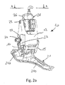
ベース体12は、自転車100のフレーム20に固定されるように意図されている。可動体14は、4バー・リンク機構11においてベース体12の反対側に位置し、チェーンガイド21を保持する。図示の実施形態において、可動体14は、チェーンガイド21との一体品とされる。
The
図示しない他の実施形態において、可動体14およびチェーンガイド21は、それぞれ別体の構成品であり、互いに接続固定されて拘束し合うものとされる。
In another embodiment (not shown), the
チェーンガイド21は、底が開いた凹形ボディ21aで構成される。前記凹形ボディ21aには、チェーンガイド21の第1の端部21cに向かって互いに平行に延びて、その第1の端部21cで互いに結合する2つのアーム21bが設けられている。
The
前記のようにして、歯車33に係合した状態の伝動チェーンは、干渉なく通過することができ、さらに、ギアシフト時には、伝動チェーンを支持すると同時にこれを持ち上げて、別の歯車33に係合させることができる。 As described above, the transmission chain engaged with the gear 33 can pass without interference. Further, at the time of gear shift, the transmission chain is supported and simultaneously lifted to be engaged with another gear 33. be able to.
好ましくは、ベース体12は、直接的に、またはストラップ27(図1)を介して、ねじカップリング(screwed coupling)で自転車100のフレーム20に連結される。前記目的のために、ベース体12は、フレーム20に当接する形状部23を有し、ねじ(threaded screw)22が形状部23から突出しており、適切なナット24で前記ねじ22をフレーム20に留めることができる。
Preferably, the
好ましくは、4バー・リンク機構型の運動機構11に、第1のクリアランス復元ばね34が設けられている。
Preferably, the first
好ましくは、第1のクリアランス復元ばね34は、可動体14と一対のコネクテイングロッド13,15のうちの1つのコネクテイングロッド13,15との間に設けられている。
Preferably, the first
第1のクリアランス復元ばね34は、第1の端部がその1つのコネクテイングロッド13,15に留められており、他方の端部が可動体14に留められている。
The first
第1のクリアランス復元ばね34は、その1つのコネクテイングロッド13,15と可動体14との間のクリアランス、概して言えば、4バー・リンク機構型の運動機構11のクリアランスを復元するように、それら1つのコネクテイングロッド13,15と可動体14との間に力を印加する。
The first
図示の実施形態では、第1のクリアランス復元ばね34が、可動体14と一対のコネクテイングロッド13,15のうちの第2のコネクテイングロッド15(すなわち、内側のコネクテイングロッド)との間に設けられている。
In the illustrated embodiment, the first
さらに、4バー・リンク機構型の運動機構11には、前記4バー・リンク機構型の運動機構11を変形させて、可動体14とベース体12との相対的な変位を決める結果、自転車100のフレーム20に対するチェーンガイド21の変位を決める、変速ギア装置の作動手段28が設けられている。
Furthermore, the 4-bar / link mechanism
前記作動手段28は、モータ式であり、モータケーシング30および前記モータケーシング30から直接突出する出力シャフト29を含む。
The actuating means 28 is of a motor type and includes a
本発明では、作動手段28が、モータケーシング30に対する出力シャフト29の軸方向並進をコマンドし、さらに、4バー・リンク機構型の運動機構11の4つのピン要素16,17,18,19と実質的に平行な第5のピン要素25を中心として傾動するための少なくとも1つの傾動インターフェース26,36を介して、前記4バー・リンク機構型の運動機構11の異なる構成品12,13,14,15間に取り付けられる。
In the present invention, the actuating means 28 commands the axial translation of the
このようにして、出力シャフト29の軸方向並進により、4バー・リンク機構型の運動機構11の構成品12,13,14,15間の相対回転を決めることができる。
In this way, the relative rotation between the
好ましくは、変速ギア装置の作動手段28は、ベース体12と一対のコネクテイングロッド13,15のうちの1つのコネクテイングロッド13,15とを接続するピン要素16,18を中心としてこれら2つの構成品間で相対回転が生じるように、ベース体12とその1つのコネクテイングロッド13,15との間に配置されている。
Preferably, the actuating means 28 of the transmission gear device has two of these centering on
図示の実施形態では、作動手段28が、ベース体12と第1のコネクテイングロッド13(すなわち、外側のコネクテイングロッド13)との間に配置されている。しかしながら、これとまったく等価的な様式で、作動手段28を、ベース体12と内側のコネクテイングロッド15との間に配置することも可能である。
In the illustrated embodiment, the actuating means 28 is disposed between the
また、作動手段28は、出力シャフト29の軸方向並進をコマンドするために、前記出力シャフト29の並進変位を直接作り出すことができるモータ要素(図示せず)を含む。あるいは、作動手段28は、ロータリー型のモータ要素を含む。
Actuating means 28 also includes a motor element (not shown) that can directly produce a translational displacement of the
後者の場合、作動手段28の構成として、様々な構成が考えられる。 In the latter case, various configurations are conceivable as the configuration of the actuation means 28.
作動手段28の第1の実施例(図示せず)では、ロータリー型のモータ要素の一次出力シャフトが、そのモータ要素によって回転されると、出力シャフト29の前記軸方向並進を決めるように、前記一次モータシャフトと出力シャフト29との間に運動学的(kinematically)に設けられたトランスミッションが始動する。前記ロータリー型のモータ要素、前記一次モータシャフトおよび前記トランスミッションは、モータケーシング30内に完全に収容されている。これにより、泥や土や残りカスの侵入を防ぐことができる。
In a first embodiment (not shown) of the actuating means 28, the primary output shaft of the rotary motor element is rotated by the motor element so as to determine the axial translation of the
前記トランスミッションの構成についても、様々なものが考えられる。好ましい一変形例(詳細な構造は図示せず)において、前記トランスミッションは、二次モータシャフト、一次モータシャフトと二次モータシャフトとの間に設けられた回転減速用のギア列、および二次モータシャフトに一体回転可能に取り付けられており且つ出力シャフト29に形成されたラックに係合するピニオンを具備している。
Various configurations of the transmission can be considered. In a preferred modification (the detailed structure is not shown), the transmission includes a secondary motor shaft, a gear train for rotation reduction provided between the primary motor shaft and the secondary motor shaft, and a secondary motor. A pinion is attached to the shaft so as to be integrally rotatable and engages with a rack formed on the
作動手段28の他の実施例(図示せず)では、前記一次モータシャフトが、ねじが切られたものとされて出力シャフト29にカップリングしている。前記実施例における詳細な一構成では、出力シャフト29が、前記一次モータシャフトのねじの対となる雌ねじが切られた中空ブッシュのように形成されている。このようにして、前記一次モータシャフトと出力シャフト29との間の相対回転が、これら2種類のシャフト間の相対的なスライドを決め、前記相対的なスライドにより、モータケーシング30に対する出力シャフト29の純粋な並進が決まる。
In another embodiment (not shown) of actuating means 28, the primary motor shaft is threaded and coupled to the
上記の詳細な一構成では、さらに、前記一次モータシャフトおよび当該一次モータシャフトと出力シャフト29との噛合インターフェース(meshing interface)が、モータケーシング30内に完全に収容されている。これにより、噛合部分に泥や土が蓄積するのを防ぐことができる。
In the detailed configuration described above, the primary motor shaft and the meshing interface between the primary motor shaft and the
作動手段28のさらなる他の実施例(図示せず)では、出力シャフト29が、ねじが切られたものとされてナットねじと噛合カップリング(meshed coupling)しており、前記ロータリー型のモータ要素および前記ナットねじが、モータケーシング30内に完全に収容されている。これにより、出力シャフト29と前記ナットねじとの噛合インターフェースに泥や土や残りカスが侵入するのを防ぐことができる。このようにして、さらに出力シャフト29と前記ナットねじとの間の相対回転により、出力シャフト29の、モータケーシング30外へのスライドが決まる。
In yet another embodiment (not shown) of the actuating means 28, the
図2a、図2b及び図2cに示す第1の実施形態では、出力シャフト29のフリーエンドがループ状の形状をしており、さらに、前記コネクテイングロッド13,15に、前記コネクテイングロッド13,15と出力シャフト29との間でピン要素16,17,18,19と平行な第6のピン要素31を中心とした相対回転が可能となるように直接接続している。これにより、出力シャフト29は、モータケーシング30に対して回転運動せずに済む。
In the first embodiment shown in FIGS. 2 a, 2 b and 2 c, the free end of the
第6のピン要素31は、コネクテイングロッド13,15の作動アーム32に形成されている。前記作動アーム32は、そのコネクテイングロッド13,15に固定的に接続され且つそのコネクテイングロッド13,15から4バー・リンク機構型の運動機構11の内部に向かって突出する一部分のような形状をしている。
The
前記実施形態において、前記傾動インターフェースは、モータケーシング30の支持シェル26の形態に形成されて、ベース体12にヒンジ接続される。前記目的のために、第5のピン要素25は、支持シェル26のうちの互いに反対側に位置する2つの座部25bに自由に回転可能に係合する、2つのハーフピン25aで構成される。
In the embodiment, the tilt interface is formed in the form of the
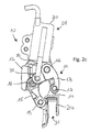
図3a、図3b及び図3cに示す第2の実施形態、ならびに図4に示す第3の実施形態では、出力シャフト29のフリーエンドと前記出力シャフト29が働きかけるコネクテイングロッド13,15との間に設けられる前記傾動インターフェースとして、異なる構成のものを採用している。
In the second embodiment shown in FIGS. 3a, 3b and 3c, and in the third embodiment shown in FIG. 4, there is a gap between the free end of the
これらの実施形態では、前記傾動インターフェースが、介在関節要素36の形態に形成されている。
In these embodiments, the tilting interface is formed in the form of an intervening
前記介在関節要素36は、一方の側が、出力シャフト29のフリーエンドにヒンジ接続されている。これにより、出力シャフト29による押圧/牽引(push/pull)が、介在関節要素36に加わり、前記介在関節要素36に加わる押圧/牽引により、第5のピン要素25を中心とする前記介在関節要素36の回転が決まる。
One side of the interposition
好ましくは、出力シャフト29のフリーエンドは、ループ状の形状をしており、介在関節要素36の第1の端部に配置される第5のピン要素25に係合する。この場合も、出力シャフト29は、モータケーシング30に対して回転運動しない。
Preferably, the free end of the
介在関節要素36の第2の端部は、コネクテイングロッド13,15に、前記コネクテイングロッド13,15と介在関節要素36との間で第6のピン要素31を中心とした相対回転が可能となるようにヒンジ接続している。第1の実施形態の説明で既述したものと同じく、第6のピン要素31は、コネクテイングロッド13,15の作動アーム32に形成されている。
The second end of the interposition
第2の実施形態および第3の実施形態では、モータケーシング30の支持シェル26が、ベース体12に接続固定されている。
In the second embodiment and the third embodiment, the
図4に示す第3の好ましい実施形態について詳細に述べる。前記実施形態では、モータケーシング30の出力シャフト29と介在関節要素36との間に、第2のクリアランス復元ばね35が設けられている。第2のクリアランス復元ばね35は、第1の端部が出力シャフト29に留められており、他方の端部が介在関節要素36に留められている。
The third preferred embodiment shown in FIG. 4 will be described in detail. In the embodiment, the second
第2のクリアランス復元ばね35は、第1のクリアランス復元ばね34と拮抗して動作するように装着・プリロード設定される。
The second
具体的には、4バー・リンク機構型の運動機構11が変形すると、第1のクリアランス復元ばね34の荷重が増加すると共に第2のクリアランス復元ばね35の荷重が減少するか、あるいは、これとは逆に第1のクリアランス復元ばね34の荷重が減少すると共に第2のクリアランス復元ばね35の荷重が増加する。
Specifically, when the 4-bar / link mechanism
以下では、本発明にかかる自転車変速ギア装置10の動作を説明する。
Below, operation | movement of the bicycle
運転者が、変速ギア装置の作動手段28を作動させることにより、出力シャフトの、モータケーシング30から突出する部分の長さの増加/減少が決まる。
When the driver operates the operating means 28 of the transmission gear device, the increase / decrease of the length of the portion of the output shaft that protrudes from the
特定の実施態様に応じて、出力シャフト29の端部がコネクテイングロッド13,15のうちの1つのコネクテイングロッドに、直接又は間接的に働きかけることにより、作動アーム32に押圧/牽引動作が加わり、前記作動アーム32に加わった押圧/牽引動作により、前記作動アーム32が設けられたコネクテイングロッド13,15が回転する。これにより、4バー・リンク機構型の運動機構11が変形する。
Depending on the particular embodiment, the end of the
出力シャフト29の端部が作動アーム32に拘束されずに単に当接しているだけの場合、前記出力シャフト29は、押圧動作しか加えることができない。それゆえ、ばねのような適切な復帰手段(図示せず)により、4バー・リンク機構型の運動機構11を元の配置に戻す。
When the end portion of the
以上の説明から、本発明にかかる自転車変速ギア装置の各種特徴および異なる特徴間での相対的な利点は明らかである。 From the above description, the various advantages of the bicycle transmission gear device according to the present invention and the relative advantages among the different features are apparent.
事実、本発明にかかる自転車変速ギア装置は、泥や土によって摩擦・変化する恐れのある部品が全くないか、あるいは、そのような部品を閉じたケーシング内で収容・保護するので、精度および応答時間の双方に関して優れた指令性能を長期にわたって維持することができる。 In fact, the bicycle transmission gear device according to the present invention has no parts that may be rubbed or changed by mud or dirt, or such parts are housed and protected in a closed casing, so accuracy and response Excellent command performance in both time can be maintained over a long period of time.
前述した実施形態のほかにも、さらなる変形例が想定され得る。そして、そのような変形例は、本発明の教示内容の範囲内に含まれる。 In addition to the embodiments described above, further modifications can be envisaged. Such variations are included within the scope of the teachings of the present invention.
事実、その時々の実施要件に応じて、前記出力シャフトを、並進タイプとしても、回転・並進タイプ(rototranslating type)としてもよい。 In fact, depending on the current implementation requirements, the output shaft may be a translation type or a rototranslating type.
また、前記変速ギア装置の作動手段は、前述した好ましい実施形態と異なる種類のものであってもよいし、4バー・リンク機構型の運動機構のうちの、前述した好ましい実施形態とは異なる構成品間に設けられてもよい。なお、前述した好ましい実施形態は、本発明を限定するものではない。 Further, the operating means of the transmission gear device may be of a type different from that of the above-described preferred embodiment, and a configuration different from the above-described preferred embodiment of the four bar / link mechanism type motion mechanism. It may be provided between goods. The preferred embodiments described above do not limit the present invention.
最後に、上記した想定可能な自転車変速ギア装置には、様々な変更や変形が施されてもよく、かつ、そのような変更及び変形の全てが、本発明に包含されることは明らかである。また、細部を、技術的に等価な構成要素に置き換えることも想定される。事実、使用する材料や寸法等は、その時々の技術的要件に応じてどのように選択されてもよい。 Finally, various changes and modifications may be made to the above-described possible bicycle transmission gear device, and it is clear that all such changes and modifications are included in the present invention. . It is also envisioned that details may be replaced with technically equivalent components. In fact, the materials, dimensions, etc. used may be selected in any way according to the technical requirements at that time.
Claims (11)
4バー・リンク機構型の運動機構(11)を備えており、
前記運動機構(11)は、ベース体(12)および可動体(14)を具備しており、前記ベース体(12)と前記可動体(14)とは、一対のコネクテイングロッド(13,15)を介して互いに接続されており、前記の一対のコネクテイングロッド(13,15)は、4つのピン要素(16,17,18,19)で、前記ベース体(12)および前記可動体(14)にヒンジ接続されており、
前記可動体(14)は、チェーンガイド(21)を保持しており、
前記4バー・リンク機構型の運動機構(11)には、前記4バー・リンク機構型の運動機構(11)を変形させて、前記ベース体(12)に対する前記可動体(14)の変位を決める結果、前記チェーンガイド(21)の変位を決める、変速ギア装置の作動手段(28)が設けられており、
前記変速ギア装置の作動手段(28)は、モータ式であり、モータケーシング(30)および前記モータケーシング(30)から直接突出する出力シャフト(29)を含む、自転車変速ギア装置(10)において、
−前記作動手段(28)は、前記モータケーシング(30)に対する前記出力シャフト(29)の軸方向並進をコマンドし、
−前記ピン要素(16,17,18,19)と実質的に平行な第5のピン要素(25)を中心として傾動するための少なくとも1つの傾動インターフェース(26,36)を介して、前記作動手段(28)は、前記4バー・リンク機構型の運動機構(11)の異なる構成品(12,13,14,15)間に取り付けられていることを特徴とする、自転車変速ギア装置(10)。 A bicycle transmission gear device (10),
It has a 4-bar link mechanism type motion mechanism (11),
The motion mechanism (11) includes a base body (12) and a movable body (14), and the base body (12) and the movable body (14) include a pair of connecting rods (13, 15). ) And the pair of connecting rods (13, 15) are four pin elements (16, 17, 18, 19), and the base body (12) and the movable body ( 14) hinged to
The movable body (14) holds a chain guide (21),
The 4-bar / link mechanism type motion mechanism (11) is deformed to change the displacement of the movable body (14) relative to the base body (12). As a result of determination, an operating means (28) of the transmission gear device for determining the displacement of the chain guide (21) is provided,
In the bicycle transmission gear device (10), the operating means (28) of the transmission gear device is of a motor type and includes a motor casing (30) and an output shaft (29) protruding directly from the motor casing (30).
The actuating means (28) command axial translation of the output shaft (29) relative to the motor casing (30);
- via the front Symbol pin element (16, 17, 18, 19) substantially parallel to the fifth pin element (25) for tilting around the at least one tilting interface (26, 36), wherein actuating means (28), characterized in that pre-Symbol 4 is mounted between bar linkage-kinematic mechanism (11) of different components (12, 13, 14, 15), a bicycle derailleur gear (10).
Applications Claiming Priority (2)
| Application Number | Priority Date | Filing Date | Title |
|---|---|---|---|
| IT000299A ITMI20130299A1 (en) | 2013-02-28 | 2013-02-28 | BICYCLE DERAILLEUR, PARTICULARLY FRONTAL DERAILLEUR, IMPROVED RELIABILITY |
| ITMI2013A000299 | 2013-02-28 |
Publications (3)
| Publication Number | Publication Date |
|---|---|
| JP2014169073A JP2014169073A (en) | 2014-09-18 |
| JP2014169073A5 JP2014169073A5 (en) | 2017-01-05 |
| JP6338886B2 true JP6338886B2 (en) | 2018-06-06 |
Family
ID=48145571
Family Applications (1)
| Application Number | Title | Priority Date | Filing Date |
|---|---|---|---|
| JP2014036355A Active JP6338886B2 (en) | 2013-02-28 | 2014-02-27 | Bicycle transmission gear device with improved reliability, especially front transmission gear device |
Country Status (6)
| Country | Link |
|---|---|
| US (1) | US9676446B2 (en) |
| EP (1) | EP2772424B1 (en) |
| JP (1) | JP6338886B2 (en) |
| CN (1) | CN104015869B (en) |
| IT (1) | ITMI20130299A1 (en) |
| TW (1) | TWI687346B (en) |
Families Citing this family (26)
| Publication number | Priority date | Publication date | Assignee | Title |
|---|---|---|---|---|
| EP1799534B1 (en) | 2004-09-15 | 2014-08-27 | Yeti Cycling LLC | Rear suspension system for a bicycle |
| US9102378B2 (en) | 2010-08-20 | 2015-08-11 | Yeti Cycling, Llc | Link suspension system |
| US9821879B2 (en) | 2010-08-20 | 2017-11-21 | Yeti Cycling, Llc | Reciprocating rail movement suspension system |
| US10766563B2 (en) | 2013-01-16 | 2020-09-08 | Yeti Cyclying, Llc | Rail suspension with integral shock and dampening mechanism |
| US9085340B1 (en) * | 2014-03-14 | 2015-07-21 | Tien Hsin Industries Co., Ltd. | Electronic front derailleur |
| US9555857B2 (en) * | 2014-06-04 | 2017-01-31 | Shimano Inc. | Bicycle front derailleur |
| US9457871B2 (en) * | 2014-09-08 | 2016-10-04 | Shimano Inc. | Bicycle front derailleur |
| US10011325B2 (en) | 2014-12-10 | 2018-07-03 | Yeti Cycling, Llc | Linear derailleur mechanism |
| US10370060B2 (en) * | 2015-10-30 | 2019-08-06 | Shimano Inc. | Bicycle electrical component assembly |
| US9873482B2 (en) * | 2015-10-09 | 2018-01-23 | Shimano Inc. | Bicycle front derailleur |
| US9714067B1 (en) * | 2016-02-29 | 2017-07-25 | Shimano Inc. | Bicycle chain device |
| IT201700015349A1 (en) * | 2017-02-13 | 2018-08-13 | Campagnolo Srl | Device for operating the front derailleur of a bicycle |
| IT201700015324A1 (en) * | 2017-02-13 | 2018-08-13 | Campagnolo Srl | Front derailleur for bicycle |
| EP3595963A4 (en) | 2017-03-17 | 2021-03-10 | Yeti Cycling, LLC | Vehicle suspension linkage |
| WO2019010394A1 (en) | 2017-07-07 | 2019-01-10 | Yeti Cycling, Llc | Vehicle suspension linkage |
| US11560199B2 (en) * | 2018-12-12 | 2023-01-24 | Brandon Rodgers | Gearshifting system comprising a linear actuator |
| TWI723397B (en) * | 2019-03-19 | 2021-04-01 | 彥豪金屬工業股份有限公司 | Bicycle rear derailleur |
| US11608139B2 (en) * | 2019-05-13 | 2023-03-21 | Shimano Inc. | Bicycle rear derailleur |
| US11192607B2 (en) * | 2019-05-30 | 2021-12-07 | Shimano Inc. | Electric front derailleur |
| US11535339B2 (en) * | 2019-08-30 | 2022-12-27 | Shimano Inc. | Bicycle derailleur |
| US11745828B2 (en) * | 2020-06-30 | 2023-09-05 | Shimano Inc. | Front derailleur and chain guide of bicycle derailleur |
| US11565772B2 (en) | 2020-06-30 | 2023-01-31 | Shimano Inc. | Bicycle derailleur, bicycle gear structure, bicycle motor unit, and front derailleur |
| US11697474B2 (en) | 2020-06-30 | 2023-07-11 | Shimano Inc. | Bicycle derailleur and link pin for bicycle derailleur |
| RU2744996C1 (en) * | 2020-08-20 | 2021-03-18 | Игорь Владимирович Логинов | Chain tension controller for two-wheeled bicycles with manual drive |
| US20220081067A1 (en) * | 2020-09-11 | 2022-03-17 | Shimano Inc. | Bicycle derailleur |
| US11787506B2 (en) * | 2021-03-30 | 2023-10-17 | Shimano Inc. | Derailleur for human-powered vehicle |
Family Cites Families (34)
| Publication number | Priority date | Publication date | Assignee | Title |
|---|---|---|---|---|
| FR1319997A (en) * | 1962-04-20 | 1963-03-01 | Shifting by chain derailment, in combined plastic and metal parts for cycles, tandems, mopeds, motorcycles or similar vehicles | |
| DE3502774A1 (en) * | 1985-01-28 | 1986-10-09 | Josef Pradler, Konstruktionsbüro, 7312 Kirchheim | Linear-drive unit |
| US5254044A (en) * | 1991-10-07 | 1993-10-19 | Anderson Paul M | Control system for adjusting bicycle gear ratios |
| IT1261090B (en) * | 1993-07-08 | 1996-05-08 | Antonio Romano | MOTORIZED SPEED CHANGE UNIT FOR BICYCLES. |
| US6676549B1 (en) * | 1998-12-18 | 2004-01-13 | Shimano, Inc. | Motion sensor for use with a bicycle sprocket assembly |
| IT1310731B1 (en) * | 1999-11-23 | 2002-02-22 | Campagnolo Srl | SPEED CHANGE DEVICE FOR BICYCLES. |
| IT1320581B1 (en) * | 2000-08-03 | 2003-12-10 | Campagnolo Srl | FRONT BIKE FRONT DERAILLEUR WITH ELECTRIC CONTROL MOTOR AND GEAR REDUCER. |
| IT1321071B1 (en) * | 2000-11-17 | 2003-12-30 | Campagnolo Srl | ACTUATOR DEVICE FOR A BIKE FRONT DERAILLEUR, WITH CONNECTION JOINT TO THE DRIVEN SHAFT. |
| DE60224503T2 (en) * | 2002-04-26 | 2009-01-08 | Campagnolo S.R.L. | Bicycle transmission |
| JP3770394B2 (en) * | 2003-02-25 | 2006-04-26 | 株式会社シマノ | Bicycle shift control device |
| EP1504989B1 (en) * | 2003-08-05 | 2012-03-21 | Campagnolo S.R.L. | Actuator device and relative nut for a bicycle gearshift, with an elastically yieldind member |
| US7467567B2 (en) * | 2004-02-24 | 2008-12-23 | Shimano, Inc. | Gear reduction apparatus for a bicycle component |
| US6979009B2 (en) * | 2004-02-26 | 2005-12-27 | Shimano Inc. | Motorized bicycle derailleur assembly |
| US7291079B2 (en) * | 2004-02-26 | 2007-11-06 | Shimano Inc. | Motorized front derailleur assembly with saver arrangement |
| US7341532B2 (en) * | 2004-02-27 | 2008-03-11 | Shimano Inc. | Electric derailleur motor unit |
| US7331890B2 (en) * | 2004-02-26 | 2008-02-19 | Shimano Inc. | Motorized front derailleur mounting member |
| DE602004007472T2 (en) * | 2004-02-27 | 2007-10-31 | Campagnolo S.R.L. | Motorized actuator for bicycle transmission, with controlled friction mechanism |
| EP1568595B1 (en) * | 2004-02-27 | 2009-04-15 | Campagnolo S.R.L. | Actuator device for a bicycle gearshift |
| US20050197222A1 (en) * | 2004-03-08 | 2005-09-08 | Shimano Inc. | Front derailleur motor unit assembly |
| US7306531B2 (en) * | 2004-04-23 | 2007-12-11 | Shimano Inc. | Electric bicycle derailleur |
| US7442136B2 (en) * | 2005-02-18 | 2008-10-28 | Shimano Inc. | Motorized bicycle derailleur assembly |
| US7503863B2 (en) * | 2005-02-18 | 2009-03-17 | Shimano Inc. | Bicycle derailleur motor unit assembly |
| JP4065286B2 (en) * | 2005-08-09 | 2008-03-19 | 株式会社シマノ | Bicycle electric derailleur |
| US7704173B2 (en) * | 2006-02-08 | 2010-04-27 | Shimano Inc. | Motorized bicycle derailleur assembly |
| US8066597B2 (en) * | 2007-03-15 | 2011-11-29 | Shimano, Inc. | Electrically operated derailleur with force overload protection |
| US7914407B2 (en) * | 2007-05-29 | 2011-03-29 | Shimano Inc. | Bicycle front derailleur assembly |
| US9776685B2 (en) * | 2011-11-24 | 2017-10-03 | Shimano Inc. | Front derailleur |
| US8979683B2 (en) * | 2012-01-31 | 2015-03-17 | Shimano Inc. | Bicycle electric actuator unit |
| US9890838B2 (en) * | 2012-10-18 | 2018-02-13 | Sram, Llc | Front gear changer |
| JP2014091384A (en) * | 2012-11-01 | 2014-05-19 | Shimano Inc | Motor unit for driving bicycle transmission |
| US9726283B2 (en) * | 2012-11-07 | 2017-08-08 | Shimano Inc. | Electric front derailleur |
| US9127766B2 (en) * | 2012-11-07 | 2015-09-08 | Shimano Inc. | Bicycle derailleur |
| US8864611B2 (en) * | 2012-12-05 | 2014-10-21 | Shimano Inc. | Front derailleur |
| JP2014213705A (en) * | 2013-04-25 | 2014-11-17 | 株式会社シマノ | Derailleur for bicycle |
-
2013
- 2013-02-28 IT IT000299A patent/ITMI20130299A1/en unknown
-
2014
- 2014-02-26 EP EP14156716.4A patent/EP2772424B1/en active Active
- 2014-02-27 TW TW103106797A patent/TWI687346B/en active
- 2014-02-27 JP JP2014036355A patent/JP6338886B2/en active Active
- 2014-02-27 US US14/191,524 patent/US9676446B2/en active Active
- 2014-02-28 CN CN201410073356.8A patent/CN104015869B/en active Active
Also Published As
| Publication number | Publication date |
|---|---|
| US9676446B2 (en) | 2017-06-13 |
| JP2014169073A (en) | 2014-09-18 |
| TWI687346B (en) | 2020-03-11 |
| ITMI20130299A1 (en) | 2014-08-29 |
| TW201441097A (en) | 2014-11-01 |
| US20140243128A1 (en) | 2014-08-28 |
| CN104015869A (en) | 2014-09-03 |
| CN104015869B (en) | 2018-05-15 |
| EP2772424A1 (en) | 2014-09-03 |
| EP2772424B1 (en) | 2016-09-21 |
Similar Documents
| Publication | Publication Date | Title |
|---|---|---|
| JP6338886B2 (en) | Bicycle transmission gear device with improved reliability, especially front transmission gear device | |
| TWI610845B (en) | Motorised bicycle gearshift, with actuation in translation of the drive shaft | |
| JP2016107982A5 (en) | ||
| JP6590468B2 (en) | Bicycle gearshift device controlled by improved precision control | |
| JP6286226B2 (en) | Bicycle gearshift device controlled by improved precision control | |
| JP5161534B2 (en) | Electric tilt steering device | |
| CN203005508U (en) | Vehicle steering device | |
| JP2012121566A (en) | Actuator device for shifting gears of bicycle, and nut used in the actuator | |
| JP2018008683A (en) | Electrically driven derailleur of bicycle | |
| JP2020522432A (en) | Free-side bearings, steering gears and steering systems | |
| CN107416118B (en) | Actuator device for a bicycle gearshift and corresponding bicycle gearshift | |
| JP2524826B2 (en) | Manual transmission gear shifting operation device | |
| US20060185461A1 (en) | Shift lever device for vehicle | |
| EP3246241B1 (en) | Actuator device for a bicycle gearshift and respective bicycle gearshift | |
| TWM452134U (en) | Derailleur | |
| JP2007203829A (en) | Steering column device | |
| JP4996405B2 (en) | Work vehicle | |
| JP6543039B2 (en) | Rack support structure for steering device | |
| JP6540402B2 (en) | Seat adjustment device | |
| JP2009154776A (en) | Electric position adjustment steering device | |
| JP2006231985A (en) | Shift lever device | |
| BE394092A (en) |
Legal Events
| Date | Code | Title | Description |
|---|---|---|---|
| A521 | Request for written amendment filed |
Free format text: JAPANESE INTERMEDIATE CODE: A523 Effective date: 20161118 |
|
| A621 | Written request for application examination |
Free format text: JAPANESE INTERMEDIATE CODE: A621 Effective date: 20161118 |
|
| A977 | Report on retrieval |
Free format text: JAPANESE INTERMEDIATE CODE: A971007 Effective date: 20170810 |
|
| A131 | Notification of reasons for refusal |
Free format text: JAPANESE INTERMEDIATE CODE: A131 Effective date: 20170829 |
|
| A521 | Request for written amendment filed |
Free format text: JAPANESE INTERMEDIATE CODE: A523 Effective date: 20171128 |
|
| TRDD | Decision of grant or rejection written | ||
| A01 | Written decision to grant a patent or to grant a registration (utility model) |
Free format text: JAPANESE INTERMEDIATE CODE: A01 Effective date: 20180424 |
|
| A61 | First payment of annual fees (during grant procedure) |
Free format text: JAPANESE INTERMEDIATE CODE: A61 Effective date: 20180509 |
|
| R150 | Certificate of patent or registration of utility model |
Ref document number: 6338886 Country of ref document: JP Free format text: JAPANESE INTERMEDIATE CODE: R150 |
|
| R250 | Receipt of annual fees |
Free format text: JAPANESE INTERMEDIATE CODE: R250 |
|
| R250 | Receipt of annual fees |
Free format text: JAPANESE INTERMEDIATE CODE: R250 |
|
| R250 | Receipt of annual fees |
Free format text: JAPANESE INTERMEDIATE CODE: R250 |