JP6338385B2 - IMAGING DEVICE, IMAGING SYSTEM, IMAGING DEVICE CONTROL METHOD, AND IMAGING DEVICE HAVING IMAGING DEVICE - Google Patents
IMAGING DEVICE, IMAGING SYSTEM, IMAGING DEVICE CONTROL METHOD, AND IMAGING DEVICE HAVING IMAGING DEVICE Download PDFInfo
- Publication number
- JP6338385B2 JP6338385B2 JP2014017341A JP2014017341A JP6338385B2 JP 6338385 B2 JP6338385 B2 JP 6338385B2 JP 2014017341 A JP2014017341 A JP 2014017341A JP 2014017341 A JP2014017341 A JP 2014017341A JP 6338385 B2 JP6338385 B2 JP 6338385B2
- Authority
- JP
- Japan
- Prior art keywords
- time
- read
- accumulation
- row
- readout
- Prior art date
- Legal status (The legal status is an assumption and is not a legal conclusion. Google has not performed a legal analysis and makes no representation as to the accuracy of the status listed.)
- Active
Links
Images


Classifications
-
- H—ELECTRICITY
- H04—ELECTRIC COMMUNICATION TECHNIQUE
- H04N—PICTORIAL COMMUNICATION, e.g. TELEVISION
- H04N25/00—Circuitry of solid-state image sensors [SSIS]; Control thereof
- H04N25/40—Extracting pixel data from image sensors by controlling scanning circuits, e.g. by modifying the number of pixels sampled or to be sampled
- H04N25/44—Extracting pixel data from image sensors by controlling scanning circuits, e.g. by modifying the number of pixels sampled or to be sampled by partially reading an SSIS array
- H04N25/445—Extracting pixel data from image sensors by controlling scanning circuits, e.g. by modifying the number of pixels sampled or to be sampled by partially reading an SSIS array by skipping some contiguous pixels within the read portion of the array
-
- H—ELECTRICITY
- H04—ELECTRIC COMMUNICATION TECHNIQUE
- H04N—PICTORIAL COMMUNICATION, e.g. TELEVISION
- H04N25/00—Circuitry of solid-state image sensors [SSIS]; Control thereof
- H04N25/50—Control of the SSIS exposure
- H04N25/53—Control of the integration time
- H04N25/531—Control of the integration time by controlling rolling shutters in CMOS SSIS
Description
本発明は、撮像装置に関するものであり、特に部分読出し機能やスキップ読出し機能を有する撮像装置、撮像システム、撮像装置の制御方法および撮像装置を有する撮影装置に関するものである。 The present invention relates to an imaging apparatus, and more particularly, to an imaging apparatus having a partial readout function and a skip readout function, an imaging system, a control method for the imaging apparatus , and an imaging apparatus having the imaging apparatus .
工場の製造ラインで人間の検査者が行う目視検査の代わりに、画像入力用の撮像装置が用いられてきている。これらの撮像装置は、マシンビジョンカメラとも呼ばれ、各種部品や製品をコンピュータやデジタル入出力機器とともに検査するために用いられている。近年では、検査精度を向上させるために、1000万以上の画素を有する撮像装置が使用されるようになってきた。また、民生用のデジタルカメラにおいても同様で、撮影画質を向上させるためにますます多画素化が進んでいる。 An imaging device for image input has been used instead of visual inspection performed by a human inspector on a factory production line. These imaging devices are also called machine vision cameras, and are used to inspect various parts and products together with computers and digital input / output devices. In recent years, in order to improve inspection accuracy, an imaging device having 10 million or more pixels has been used. The same applies to consumer digital cameras, and the number of pixels is increasing in order to improve the image quality.
多画素化、高画質化のニーズが高まってきたことを受け、近年ではカメラに用いられる撮像素子としてはローリングシャッター方式のCMOSセンサが多く用いられている。ローリングシャッター方式では、撮像素子の行ごとに順次露光させる方式である。このため、センサに露光させるための露光時間の設定も行単位で行われる。 In response to the growing demand for higher pixels and higher image quality, rolling shutter type CMOS sensors are often used in recent years as image sensors used in cameras. The rolling shutter method is a method in which exposure is sequentially performed for each row of the image sensor. For this reason, the exposure time for exposing the sensor to the sensor is also set for each row.
このような撮像装置で動画を撮像し、画素配列の全画素から信号を読み出す場合、画素数が多いと読出し時間が長くなる。これにより、動画撮影の場合、1秒あたりの撮像枚数が減少する。また、撮像した映像を外部に出力するデータ量が多くなるため、フレームレートが低下する。例えば、マシンビジョンカメラでは、撮像する画素数に伴って、読出し時間の合計時間が変化するとともに、撮像装置外部に送出する画素数に伴って、フレームレートが変化することとなる。 When a moving image is picked up by such an image pickup device and a signal is read out from all the pixels in the pixel array, the reading time becomes long when the number of pixels is large. As a result, in the case of moving image shooting, the number of images taken per second decreases. In addition, since the amount of data for outputting the captured video to the outside increases, the frame rate decreases. For example, in a machine vision camera, the total readout time changes with the number of pixels to be imaged, and the frame rate changes with the number of pixels sent to the outside of the imaging device.
マシンビジョンカメラが用いられる検査システムでは、検査時間の短縮化も同時に求められている。そこで、カメラで撮像される領域のうち、関心領域のみの画素信号を読み出すことによって読出し画素数を減らし、これによりフレームレートを高速化することが行われる。フレームレートが高速化することができれば、システム全体の検査時間を短縮することができる。 In an inspection system using a machine vision camera, reduction of the inspection time is also required at the same time. Therefore, the number of pixels to be read out is reduced by reading out the pixel signal of only the region of interest out of the region imaged by the camera, thereby increasing the frame rate. If the frame rate can be increased, the inspection time of the entire system can be shortened.
一方、ローリングシャッター方式では、光電変換のための蓄積処理と光電変換された信号の読出し処理とが密接に連携している。例えば、関心領域の選択によって読出し時間の合計時間が短縮化されると、センサの一部の領域における蓄積時間が変化する場合がある。このとき、センサ全域に一様な露光時間とならないため、輝度ムラが発生する可能性がある。 On the other hand, in the rolling shutter system, accumulation processing for photoelectric conversion and readout processing of a signal subjected to photoelectric conversion are closely linked. For example, if the total readout time is shortened by selecting the region of interest, the accumulation time in some regions of the sensor may change. At this time, since the exposure time is not uniform over the entire area of the sensor, uneven brightness may occur.
そこで、特許文献1では、1枚の撮影シーケンスにおいて、行ごとに蓄積時間が異なる場合、その蓄積時間の差による輝度差を補正値により補正している例が開示されている。特許文献1によれば、行をスキップすることにより発生する行間の輝度のギャップを低減させることができるとしている。
Therefore,
また、特許文献2では、スキップ読出し時に、イメージセンサのNULL領域およびOB領域をスキップした際に発生する画質の劣化を課題としている。OB領域の撮像信号に基づいて、撮影画像の黒レベルを決めるため、OB領域をスキップしてしまうと黒レベルの精度が悪化する可能性がある。そこで、特許文献2では撮像信号の読出し時、NULL領域はスキップし、OB領域は読み出すことで、画質の劣化を低減させている。
Japanese Patent Application Laid-Open No. 2004-228561 has a problem of image quality degradation that occurs when the NULL area and the OB area of the image sensor are skipped during skip reading. Since the black level of the captured image is determined based on the imaging signal of the OB area, if the OB area is skipped, the accuracy of the black level may deteriorate. Therefore, in
しかしながら、特定の撮影条件においては、特許文献1で示されているような補正値やオフセット手段による補正が有効であるといえるが、様々な撮影シーンに対応するためには膨大な補正値を保持する必要がある。また、このような補正処理を撮影後に後処理した場合は、画質が低下してしまう可能性がある。
However, under specific shooting conditions, it can be said that correction values such as those disclosed in
特許文献2では、ローリングシャッターの長い露光における撮像では効果が見られるが、高速シャッターを用いた場合は、行間における露光時間の違いが生じ、輝度ムラが発生する可能性がある。
In
一方で、検査用途で用いられるカメラは、様々な露光時間が設定され、スキップ設定値もニーズに応じて様々である。これに加え、検査用途のカメラでは、高画質で高精細な撮影画像が求められる。画質を最適に保つためには、1枚の撮影シーケンスにおいて、あるいは動画撮影時のフレーム間において、イメージセンサの全領域が同じ蓄積時間で露光されることが望ましい。 On the other hand, various exposure times are set for cameras used in inspection applications, and skip setting values vary depending on needs. In addition, cameras for inspection use require high-quality and high-definition captured images. In order to keep the image quality optimal, it is desirable that the entire area of the image sensor is exposed with the same accumulation time in one image capturing sequence or between frames during moving image capturing.
本発明の目的は、ローリングシャッター方式のイメージセンサを備える撮像装置において、様々な露光時間およびスキップ読出しに対応し、かつ輝度ムラを低減させることができる撮像装置、撮像システム、撮像装置の制御方法および撮像装置を有する撮影装置を提供することである。 An object of the present invention is to provide an imaging apparatus , an imaging system, an imaging apparatus control method, and an imaging apparatus that can cope with various exposure times and skip readings and reduce luminance unevenness in an imaging apparatus including a rolling shutter type image sensor. An imaging device having an imaging device is provided.
本発明の撮像装置は、ローリングシャッター方式のイメージセンサと、イメージセンサの読出し単位行あたりの信号読出し時間に基づいて蓄積時間に対応するカウント数を算出するカウント数算出手段と、前記イメージセンサの読出し行及びスキップ行の単位パターンの行数であるスキップ単位を設定する設定手段と、前記スキップ単位に基づき、イメージセンサで蓄積動作または読出し動作の少なくとも一方に関する処理をスキップする行であるスキップ行を設定するスキップ設定手段と、カウント数およびスキップ行に基づき、1フレーム内における前記読出し単位行の蓄積時間が一定と1フレーム内における前記読出し単位行の蓄積時間が一定となるように、イメージセンサの蓄積動作及び読出し動作を制御する制御手段と、を有し、前記カウント数算出手段は、前記蓄積時間と、読出し領域の単位行あたりの読出し時間と、前記読出し領域と、前記スキップ単位と、に基づいて前記カウント数を設定し、前記蓄積時間が全ての読出し対象の画素信号を読み出すための読出し時間以上の場合は、前記蓄積時間と前記スキップ単位とに基づいてカウント数を算出し、前記蓄積時間が前記読出し時間より短い場合は、前記蓄積時間と前記読出し領域の読出し対象の行数とに基づいて前記カウント数を算出することを特徴とする。
本発明の撮像システムは、ローリングシャッター方式のイメージセンサと、前記イメージセンサの読出し単位行あたりの信号読出し時間に基づいて蓄積時間に対応するカウント数を算出するカウント数算出手段と、前記イメージセンサの読出し行及びスキップ行の単位パターンの行数であるスキップ単位を設定する設定手段と、前記スキップ単位に基づき、前記イメージセンサで蓄積動作または読出し動作の少なくとも一方に関する処理をスキップする行であるスキップ行を設定するスキップ設定手段と、前記カウント数および前記スキップ行に基づき、1フレーム内における前記読出し単位行の蓄積時間が一定となるように、前記イメージセンサの蓄積動作及び読出し動作を制御する制御手段と、を有し、前記カウント数算出手段は、前記蓄積時間と、読出し領域の単位行あたりの読出し時間と、前記読出し領域と、前記スキップ単位と、に基づいて前記カウント数を設定し、前記蓄積時間が全ての読出し対象の画素信号を読み出すための読出し時間以上の場合は、前記蓄積時間と前記スキップ単位とに基づいてカウント数を算出し、前記蓄積時間が前記読出し時間より短い場合は、前記蓄積時間と前記読出し領域の読出し対象の行数とに基づいて前記カウント数を算出することを特徴とする。
本発明の撮像装置の制御方法は、ローリングシャッター方式のイメージセンサの読出し単位行あたりの信号読出し時間に基づいて蓄積時間に対応するカウント数を算出するステップと、前記イメージセンサの読出し行及びスキップ行の単位パターンの行数であるスキップ単位を設定するステップと、前記スキップ単位に基づき、前記イメージセンサで蓄積動作または読出し動作の少なくとも一方に関する処理をスキップする行であるスキップ行を設定するステップと、前記カウント数および前記スキップ行に基づき、1フレーム内における前記読出し単位行の蓄積時間が一定となるように、前記イメージセンサの蓄積動作及び読出し動作を制御するステップと、を有し、カウント数を算出する前記ステップは、前記蓄積時間と、読出し領域の単位行あたりの読出し時間と、前記読出し領域と、前記スキップ単位と、に基づいて前記カウント数を設定し、前記蓄積時間が全ての読出し対象の画素信号を読み出すための読出し時間以上の場合は、前記蓄積時間と前記スキップ単位とに基づいてカウント数を算出し、前記蓄積時間が前記読出し時間より短い場合は、前記蓄積時間と前記読出し領域の読出し対象の行数とに基づいて前記カウント数を算出する、ことを特徴とする。
An image pickup apparatus according to the present invention includes a rolling shutter type image sensor, count number calculating means for calculating a count number corresponding to an accumulation time based on a signal reading time per reading unit row of the image sensor, and reading of the image sensor. Setting means for setting a skip unit that is the number of unit patterns of lines and skip lines, and a skip line that is a line for skipping processing related to at least one of the accumulation operation and the read operation by the image sensor based on the skip unit. Based on the skip setting means, the number of counts and skip rows, the accumulation of the image sensor so that the accumulation time of the readout unit row in one frame is constant and the accumulation time of the readout unit row in one frame is constant. possess control means for controlling the operation and read operation, the, The count number calculating means sets the count number based on the accumulation time, the readout time per unit row of the readout area, the readout area, and the skip unit, and the accumulation time is all read out. When the readout time is longer than the readout time for reading out the target pixel signal, the count number is calculated based on the accumulation time and the skip unit, and when the accumulation time is shorter than the readout time, the accumulation time and the readout The count number is calculated based on the number of rows to be read from the area .
An image pickup system according to the present invention includes a rolling shutter type image sensor, a count number calculating unit that calculates a count number corresponding to an accumulation time based on a signal reading time per reading unit row of the image sensor, Setting means for setting a skip unit, which is the number of unit patterns of a read row and a skip row, and a skip row that skips processing related to at least one of an accumulation operation and a read operation in the image sensor based on the skip unit. And a control unit for controlling the accumulation operation and the read operation of the image sensor so that the accumulation time of the read unit row in one frame is constant based on the count number and the skip row. And the count number calculating means includes the The count number is set based on the product time, the readout time per unit row of the readout area, the readout area, and the skip unit, and the accumulation time for reading out all readout target pixel signals If it is equal to or longer than the read time, the count number is calculated based on the accumulation time and the skip unit. If the accumulation time is shorter than the read time, the accumulation time and the number of rows to be read in the read area are calculated. The count number is calculated based on the above.
The method for controlling an imaging apparatus according to the present invention includes a step of calculating a count corresponding to an accumulation time based on a signal readout time per readout unit row of a rolling shutter type image sensor, and readout rows and skip rows of the image sensor. A step of setting a skip unit that is the number of lines of the unit pattern, and a step of setting a skip line that is a line that skips processing related to at least one of an accumulation operation or a read operation in the image sensor based on the skip unit; Controlling the accumulation operation and readout operation of the image sensor so that the accumulation time of the readout unit row in one frame is constant based on the count number and the skip row, and the count number The step of calculating includes the accumulation time and the readout area. The count number is set based on the readout time per rank, the readout area, and the skip unit, and when the accumulation time is equal to or longer than the readout time for reading out all readout target pixel signals, A count number is calculated based on the accumulation time and the skip unit, and when the accumulation time is shorter than the read time, the count number is calculated based on the accumulation time and the number of rows to be read in the read area. It is characterized by calculating.
本発明によれば、関心領域の設定変更があっても露出が維持され、かつ関心領域の設定変更に伴う画質の悪化を低減可能な撮像装置、撮像システム、撮像装置の制御方法および撮像装置を有する撮影装置を提供することができる。 According to the present invention, even when a setting change of the region of interest is maintained exposed, and can reduce the imaging apparatus image deterioration due to the setting change of the region of interest, the imaging system, a control method and an imaging apparatus of the imaging apparatus It is possible to provide a photographing apparatus having the same.
以下に、本発明の好ましい実施の形態を、添付の図面に基づいて詳細に説明する。図1は、本発明の実施形態にかかわる構成図である。 Hereinafter, preferred embodiments of the present invention will be described in detail with reference to the accompanying drawings. FIG. 1 is a configuration diagram according to an embodiment of the present invention.
図1に本発明の第1の実施例の撮像装置の構成図を示す。 FIG. 1 shows a configuration diagram of an image pickup apparatus according to the first embodiment of the present invention.
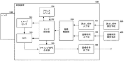
撮像装置100は、イメージセンサ101を含む撮像系を有し、センサ制御部102およびADC(AD変換器)103、アドレスカウンタ104によって撮像処理を行う。レンズ200は、撮像装置100の外部に構成され、撮像装置100とレンズ200で撮影装置を構成する。レンズ200を通った光束は、撮像装置100のイメージセンサ101上に結像する。レンズ200は、不図示の絞り群、変倍レンズ群、フォーカスレンズ群などの要素から構成される。また、レンズ200に構成される変倍レンズ群は、焦点距離が可変でも固定でも良い。センサ制御部102は、イメージセンサ101の蓄積動作や読出し動作の制御を行う。センサ制御部102によってイメージセンサ101の撮像処理を行うと、イメージセンサ101からは撮像信号が出力され、ADC103にてAD変換される。アドレスカウンタ(スキップ設定手段)104は、センサ制御部102が蓄積制御と読出し制御を行うイメージセンサ101の対象行あるいは対象画素となるアドレスを算出する。イメージセンサ101からのスキップ読出しを行う場合は、イメージセンサ101の全画素のうち、読出しを行う画素を対象画素としてアドレス出力し、読出し対象とならないアドレスはスキップする。タイミング信号合成部105は、ADC103からの撮像信号データとアドレスカウンタ104からの信号とを、センサ制御部102を介して入力し、撮像信号データに対し、フレーム同期信号や垂直同期信号、水平同期信号などを合成する。
The
読出し条件設定手段300は、撮像装置100の外部から、前記イメージセンサからの画素データ読出し制御に関する条件である、関心領域(読出し領域)となる領域の座標データやスキップ単位行数等を設定する。スキップ単位行数についての説明は後述する。たとえば、読出し条件設定手段300としてPCを使用する。読出し条件入力部107は、読出し条件設定手段300で入力された設定データを入力し保持する。
The reading condition setting means 300 sets, from the outside of the
蓄積時間設定手段400は、撮像装置100の外部から撮像装置100のシャッター速度としての蓄積時間を設定する。読出し条件設定手段400として、たとえばPCを使用する。蓄積時間入力部108は、イメージセンサ101の全画素を蓄積及び読出しするための範囲設定値を保持している。なお、前述の読出し条件設定手段300と蓄積時間設定手段400とを同一のPC内に構成しても良い。
The accumulation time setting unit 400 sets the accumulation time as the shutter speed of the
蓄積制御部109は、読出し条件入力部107と蓄積時間入力部108からの設定データを入力する。また、蓄積制御部109は、読出し条件入力部107で保持された読出し設定データを、センサ制御部102を介してアドレスカウンタ104へ出力する。
The accumulation control unit 109 inputs setting data from the read
画像信号出力部(画像信号出力手段)106は、タイミング信号合成部105から出力される撮像信号データにおいて、読出し条件入力部107で入力された読出し領域と、撮像信号の各関心領域の座標の対応が取れるように、必要なタイミング信号を加え、出力画像信号を生成する。画像信号出力部106は、タイミング信号合成部105で生成された出力画像信号を撮像装置100の外部へ出力する。
The image signal output unit (image signal output means) 106 corresponds to the correspondence between the readout region input by the readout
図2にイメージセンサ101の構造図を示す。図2のImgは、撮像素子を示している。図2中の11から33までは、撮像素子Imgに構成される画素配列の一部を示している。撮像素子Imgの撮像領域内の各画素には、V1、V2、V3、・・・およびH1、H2、H3を通じて、垂直回路1011および水平回路1012に接続されている。
FIG. 2 shows a structural diagram of the image sensor 101. Img in FIG. 2 indicates an image sensor. Reference numerals 11 to 33 in FIG. 2 indicate a part of the pixel array configured in the image sensor Img. Each pixel in the imaging region of the imaging element Img is connected to the
図2の垂直回路1011へは、3つの制御線ChargeReset、ReadReset、LineShiftが接続されている。これらの制御線は、図1のセンサ制御部102と接続されている。垂直回路1011内部には、不図示の蓄積対象行選択レジスタと読出し対象行選択レジスタが構成されている。各行選択レジスタは、撮像素子Img中の各ラインの蓄積対象行と読出し対象行をそれぞれ選択することができる。制御線ChargeResetは、各行選択レジスタによって選択されている蓄積対象行を先頭行にリセットし、先頭行の蓄積を開始する。制御線ReadResetは、行選択レジスタによって選択されている読出し対象行を先頭行にリセットする。制御線LineShiftは、行選択レジスタが選択している蓄積対象行と読出しし対象行をインクリメントするための制御線である。制御線LineShiftにHi信号を1回入力すると、各行選択レジスタが選択している対象の次の行が参照される。本実施例では、制御線LineShiftが1本の場合の例について説明するが、蓄積対象行選択レジスタと読出し対象行選択レジスタが参照する行を個別にインクリメントするために別々に構成しても良い。
Three control lines ChargeReset, ReadReset, and LineShift are connected to the
図2の水平回路1012へは、2つの制御線TransferH、Hpulseが接続されている。これらの制御線は、上述の垂直回路1011と同様に、図1のセンサ制御部102に接続されている。上述の制御線LineShiftへのワンショットパルス入力後、制御線TransferHは、垂直回路1011の行選択レジスタによって選択されている読出し対象行の画素データを水平回路1012に転送する。例えば、行選択レジスタによって選択されている読出し対象行がV2のとき、制御線TransferHによって、21、22,23の撮像信号が水平回路1012に転送される。制御線Hpulseは、水平回路1012に転送された撮像信号を読み出すための制御線である。制御線Hpulseに読出し制御のためのパルスが入力されると、図2のアンプ1013を通じて、outから撮像信号がアナログ出力される。この撮像信号は、図1のADC103に接続されている。ADC103は制御線Hpulseに同期して、ADC103に入力された撮像信号をAD変換する。制御線Hpulseは、読出しを行う画素数分のクロックを発生している。
Two control lines TransferH and Hpulse are connected to the
ここで、イメージセンサ101の撮像制御の例について図3および図4を用いて説明する。イメージセンサ101はローリングシャッター方式のイメージセンサである。ここでは、イメージセンサ101の読出し対象行数をn行として説明する。後述するが、読出し対象となるn行分の読出し時間と1行あたりの蓄積時間を比較し、その大小関係で2種類の撮像制御方式を切り替える。1行あたりの蓄積時間がn行分の読出し時間以上である場合における撮像制御の例を図3に示す。 Here, an example of imaging control of the image sensor 101 will be described with reference to FIGS. The image sensor 101 is a rolling shutter type image sensor. Here, the number of rows to be read by the image sensor 101 is assumed to be n rows. As will be described later, the readout time for n rows to be read out is compared with the accumulation time per row, and the two types of imaging control methods are switched depending on the magnitude relationship. FIG. 3 shows an example of imaging control when the accumulation time per row is longer than the readout time for n rows.
図3では、前述の垂直回路1011に制御線ChargeResetとReadResetおよびLineShiftが接続された図と、上部にタイミングチャートを示している。図3では横軸が時間方向を示している。また、図3下部の縦軸はイメージセンサ101の行方向の蓄積・読出しイメージを示している。まず、時間p01で制御線ReadResetとLineShiftにパルスを入力することで、イメージセンサ101の第1行目の読出しを開始している。時間p01での制御線LineShiftパルスの入力後、図3では不図示の水平回路1012の制御線TransferH、Hpulseを用いて、第1行目の画素信号の読出しを行っている。画素信号の読出し時には、図1のADC103によって制御線Hpulse に同期したAD変換がなされる。図3で示すTReadlineは、1行分の画素信号の読出しに要する時間である。1行分の読出しが完了した後、時間p02で制御線LineShiftおよびChargeResetにワンショットパルスを入力している。なお、Treadlineは、p01とp02の間隔時間と同等である。また、TReadlineは、時間p01、p02などで入力される制御線LineShiftへのワンショットパルスのHi時間よりも十分長い。ここでは、垂直回路1011の行選択レジスタによって、読出し対象行は第2行が選択され、蓄積対象行として第1行が選択されている。時間p01からp02にかけて第1行の画素信号が読みだされた後、時間p02において第1行の蓄積を開始することとなる。また、時間p02からp03にかけて前述と同様にしてTReadlineの時間で第2行の画素信号が読みだされることとなる。また、図3の「読出し中の領域」「蓄積中の領域」で示されるように、各行間はTReadlineの時間分の時間差で、蓄積および読出しが行われることとなる。以下同様にして、時間p01からp0nまでの時間においてイメージセンサの最終行nまでの蓄積と読出しが行われると、再び時間p11で第一行目からの読出しが行われる。時間p11では、上述の時間p01で行われた水平回路1012への処理と同様の処理が行われる。また、時間p11で読みだされる第一行目の撮像信号は、時間p02からp11までに蓄積されたものである。また、例えば、時間p12で読みだされる第二行目の撮像信号は、時間p03からp12までに蓄積されたものである。時間p01からp0nまでで読みだされる撮像信号は、カメラ起動後の第0フレームであり、ダミーの読出しとしている。図3に示すFrameValid信号は、上記第0フレームにおいて蓄積された撮像信号を読み出す時間p11以降、すなわち第1フレーム以降の毎フレームで有効とし、時間p01からp0nまでに読みだされる第0フレームの撮像信号を無効としている。
FIG. 3 shows a diagram in which control lines ChargeReset, ReadReset, and LineShift are connected to the
このように、図3では、時間p01からp0nまで順次第0フレームの読出しを行いつつ、p02以降は各行で第1フレームとして出力するための蓄積動作を順次開始させている。図3で示すように、第一行から最終行nまでの読出し時間をTread_Aとして図示している。上述のTreadlineに行数nを掛けた時間がTread_Aとなる。Tcharge_Aは、第一行の蓄積時間を示している。図3では第一行から最終行nまでの各行の蓄積時間Tcharge_AはTcharge_A0と等しく、一様である。また、図3に示すTread_AをTread、Tcharge_AをTchargeとすると、図3におけるTchargeとTreadの関係は以下の式(1)の通りである。
Tcharge ≧ Tread ・・・(1)
As described above, in FIG. 3, the 0th frame is sequentially read from time p01 to p0n, while the accumulation operation for outputting as the first frame in each row is sequentially started after p02. As shown in FIG. 3, the read time from the first row to the last row n is shown as Tread_A. The time obtained by multiplying the above Treadline by the number of lines n is Tread_A. Tcharge_A indicates the accumulation time of the first row. In FIG. 3, the accumulation time Tcharge_A of each row from the first row to the last row n is equal to Tcharge_A0 and is uniform. Further, assuming that Tread_A shown in FIG. 3 is Tread and Tcharge_A is Tcharge, the relationship between Tcharge and Tread in FIG. 3 is expressed by the following equation (1).
Tcharge ≧ Tread (1)
上述の式(1)の関係とは異なり、以下の式(2)で示す関係の場合、図4に示すような撮像制御を行う。
Tcharge < Tread ・・・(2)
Unlike the relationship of the above equation (1), in the case of the relationship represented by the following equation (2), imaging control as shown in FIG. 4 is performed.
Tcharge <Tread (2)
図4では図3と同様に、垂直回路1011に制御線ChargeResetとReadResetおよびLineShiftが接続され、上部にタイミングチャートを示している。まず、時間p01で制御線ChargeResetおよびLineShiftにワンショットパルスを入力することで、イメージセンサ101の第1行目の蓄積を開始する。次に、時間p02で制御線LineShiftにワンショットパルスを入力することで、第2行目の蓄積を開始する。時間p01とp02の間隔時間は、図3と同様にTreadlineである。同様にして、Treadline分の時間間隔で、すなわち時間p01, p02, ・・・ p0k, ・・・ で制御線LineShiftにワンショットパルスを入力していく。このように制御線LineShiftにワンショットパルスを入力していくことによって、イメージセンサ101の第1行、第2行、・・・ 第k行、・・・というようにTreadlineの時間ずれを伴って順次蓄積を開始していく。そして、時間p01+Tcで制御線ReadResetおよびLineShiftにワンショットパルスを入力すると、イメージセンサ101の第1行の蓄積を終了させる。時間p01+Tcでのワンショットパルス入力後、前述の図3と同様に、不図示の水平回路1012の制御線TransferH、Hpulseを用いて、第1行目の画素信号の読出しを行う。ここでは、時間p01からp01+Tcまで、すなわち、Tcharge_Bの蓄積時間で蓄積された撮像信号を読み出す。ここで、Tcとは一行あたりの蓄積時間Tcharge_BをTreadlineで割った値である。また、時間p01+Tcでは、第1行の読出しと同時に第Tc行の蓄積を開始している。以降、図3と同様の読出し方法により、時間p01+Tc以降、Treadlineの時間差を伴って、最終行である第n行目まで順次1行ずつ読出しが行われる。このようにイメージセンサ101の全行を読み出す時間はTread_Bで与えられる。読出しライン数が等しければ、Tread_Bは図3で示したTread_Aと等しい。
4, similarly to FIG. 3, control lines ChargeReset, ReadReset, and LineShift are connected to the
このように、式(2)の条件における図4の撮像制御では、読出し時間よりも蓄積時間の方が短い場合に行われる撮像制御の一例であり、第一行の読出しが開始した時刻以降に、第Tc行以降の蓄積が開始されていく。連続的に撮影を行う場合は、読出し対象とする行すべての読出しが終了した後に、次のフレームの蓄積や読出しを行う。 4 is an example of the imaging control performed when the accumulation time is shorter than the readout time in the condition of the expression (2), and after the time when the first row readout is started. The accumulation after the Tc line is started. In the case of continuous shooting, the storage and reading of the next frame is performed after reading of all the rows to be read is completed.
以上の撮像制御の例を踏まえ、本実施例では、撮像信号を4行単位で読出しおよびスキップを行う撮像例について説明する。図5にイメージセンサ101が2000行の撮像素子で構成されている例を示す。本実施例では、斜線部で示すように4k行(kは自然数)を読み出し、かつ4k-1行、4k-2行、4k-3行をスキップする場合において、各行の蓄積時間を同等とする例について説明する。本実施例において撮像装置100が行う処理のフローチャートを図6に示す。撮像装置100に電源が投入されると、図6に示すステップS110から順番に処理を実行していく。
In the present embodiment, based on the above example of imaging control, an imaging example in which an imaging signal is read and skipped in units of four rows will be described. FIG. 5 shows an example in which the image sensor 101 is composed of 2000 rows of image sensors. In the present embodiment, as shown by the hatched portion, when 4k rows (k is a natural number) are read and 4k-1 rows, 4k-2 rows, and 4k-3 rows are skipped, the accumulation time of each row is made equal. An example will be described. FIG. 6 shows a flowchart of processing performed by the
まず、図6のフローチャートのステップS110ではスキップ設定の入力を行う。前述の図1の読出し条件設定手段300によって、読出し条件入力部107を通じて入力される。ここでは、スキップ設定値としてスキップ単位を入力する。本発明において、スキップ単位とは、読出し行とスキップ行の繰り返しの単位パターンの行数を表現するための単位と定義する。上述したように、本実施例では4行を単位として読出しおよびスキップを行うため、スキップ単位としては「4」となる。つまり前述のスキップ単位の定義によれば、1行の読出しと3行のスキップを行うことを意味する。読出設定値は図1の読出設定入力部107で保持され、蓄積制御部109に入力される。図6のステップS110が実行されると、次にステップS120へ進む。
First, in step S110 in the flowchart of FIG. 6, a skip setting is input. The data is input through the read
ステップS120では、所謂シャッター速度(蓄積時間の入力を行う。ここでは、図1の蓄積時間設定手段400によって、蓄積時間入力部108を通じて入力される。蓄積時間は図1の蓄積時間入力部108で保持され、蓄積制御部109に入力される。蓄積時間は一般的には1/250、1/500などで示され、単位として「秒」が用いられることが多いが、「ミリ秒」として実施しても良い。本発明で説明する蓄積時間とは、あくまで実時間としての時間である。図6のステップS120が実行されると、次にステップS130へ進む。 In step S120, the so-called shutter speed (accumulation time is inputted. Here, the accumulation time is input by the accumulation time setting means 400 of FIG. 1 through the accumulation time input unit 108. The accumulation time is inputted by the accumulation time input unit 108 of FIG. It is held and input to the accumulation control unit 109. The accumulation time is generally indicated as 1/250, 1/500, etc., and “second” is often used as the unit, but it is implemented as “millisecond”. The accumulation time described in the present invention is the actual time, and when step S120 in Fig. 6 is executed, the process proceeds to step S130.
ステップS130では、蓄積制御部(カウント数設定手段)109において蓄積行数の変換演算を行う。図6のステップS130のサブルーチンを図7に示す。まず、図7のステップS131では、イメージセンサ101の1行あたりの読出し時間を算出する。図3および図4での説明の通り、TReadlineは1行分の画素信号の読出しに要する時間である。TReadline は、制御線LineShiftへのワンショットパルスから制御線TransferHによる読出し対象行の画素データ転送までの時間と、制御線Hpulseによる読出し時間とを加算した時間である。このうち、制御線TransferHによる読出し対象行の画素データ転送までの時間は、あらかじめ固定値として保持して良い。また、Hpulseによる読出し時間については、1行あたりの読出し画素数に依存するため、読出しパルス周期時間に1行あたりの読出し画素数を乗じた時間に、所定のオーバーヘッド時間を加算した時間を算出する。なお、制御線Hpulse読出しパルス周期は、イメージセンサ101の仕様で定められる固定の時間として良い。これら上述の固定値は、不図示のメモリに保持しておいても良いし、センサ制御部102あるいは蓄積制御部109などで保持しておいても良く、実装手段は限定されない。図7のフローチャートの説明に戻る。ステップS131にて1行あたりの読出し時間が算出されると、ステップS132へと進む。
In step S130, the accumulation control unit (count number setting means) 109 performs conversion calculation of the number of accumulated rows. FIG. 7 shows a subroutine of step S130 in FIG. First, in step S131 of FIG. 7, the readout time per line of the image sensor 101 is calculated. As described with reference to FIGS. 3 and 4, TReadline is the time required to read out pixel signals for one row. TReadline is a time obtained by adding the time from the one-shot pulse to the control line LineShift to the pixel data transfer of the read target line by the control line TransferH and the read time by the control line Hpulse. Among these, the time until the pixel data transfer of the read target row by the control line TransferH may be held as a fixed value in advance. Also, since the readout time by Hpulse depends on the number of readout pixels per row, a time obtained by adding a predetermined overhead time to the time obtained by multiplying the readout pulse cycle time by the number of readout pixels per row is calculated. . The control line Hpulse readout pulse cycle may be a fixed time determined by the specifications of the image sensor 101. These above-mentioned fixed values may be held in a memory (not shown) or may be held by the
図7のステップS132では、蓄積行数の算出を行う。ここで、「蓄積行数」とは、ステップS120で入力された蓄積時間を、ステップS131で算出された1行あたりの読出し時間で割ることによって算出される値である。蓄積時間と1行あたりの読出し時間が与えられると、蓄積時間を蓄積行数という単位に変換することができる。蓄積行数という単位を用いることによって、1行あたりの読出し画素数および読出し時間に依存せずに蓄積時間(シャッター速度、露光時間)を扱う(制御する)ことが可能となる。すなわち、読出し開始或いは蓄積開始(蓄積リセット)を指令するとともに、対象行を次の行に移すために使用される制御パルスをカウントすることにより、読出し開始及び蓄積開始と蓄積時間とをシンクロさせて制御することが可能となる。蓄積行数を制御に使用するため、蓄積行数は整数である必要があり、小数点以下の値については切り捨てても良いし、四捨五入するなどしても良い。本発明においては、このようにして丸められた整数の蓄積行数(カウント数)を蓄積時間設定手段400より入力された蓄積時間に対応する値として用いて制御を行う。しかし、蓄積時間(シャッター速度)及び蓄積時間として通常設定可能な間隔に対し、1行あたりの読出し時間が非常に短いことを考慮すると、上記の丸め処理で得られる蓄積行数と設定された蓄積時間は、制御に対して十分に対応している値であると言える。ステップS132が実行されると、図7のサブルーチンを終了し、図6のステップS140に進む。 In step S132 in FIG. 7, the number of accumulated rows is calculated. Here, the “number of accumulated rows” is a value calculated by dividing the accumulation time input in step S120 by the read time per row calculated in step S131. Given the accumulation time and the read time per line, the accumulation time can be converted into units of accumulated lines. By using the unit of accumulated rows, it is possible to handle (control) the accumulated time (shutter speed, exposure time) without depending on the number of read pixels per row and the read time. That is, by instructing readout start or accumulation start (accumulation reset), and counting the control pulses used to move the target row to the next row, the readout start and accumulation start are synchronized with the accumulation time. It becomes possible to control. Since the number of accumulated rows is used for control, the number of accumulated rows needs to be an integer, and values after the decimal point may be rounded down or rounded off. In the present invention, the control is performed using the integer accumulated row number (count number) rounded in this way as a value corresponding to the accumulated time input from the accumulated time setting means 400. However, considering that the readout time per line is very short compared to the interval that can usually be set as the accumulation time (shutter speed) and the accumulation time, the number of accumulation lines obtained by the above rounding process and the set accumulation It can be said that the time is a value sufficiently corresponding to the control. When step S132 is executed, the subroutine of FIG. 7 is terminated, and the process proceeds to step S140 of FIG.
図6のステップS140では蓄積・読出し方式の設定を行う。ステップS140の蓄積・読出し方式の設定のサブルーチンを図8に示す。図8ではまずステップS141にて、関心領域(読出し対象)の範囲に含まれる行数である読出し行数の算出を行う。本実施例では図5に示した通り、読出し対象は2000行である。そのため、ステップS141において、読出し行数は2000行となる。 In step S140 in FIG. 6, the storage / readout method is set. FIG. 8 shows a subroutine for setting the storage / readout method in step S140. In FIG. 8, first, in step S141, the number of read lines, which is the number of lines included in the region of interest (read target), is calculated. In this embodiment, as shown in FIG. 5, the read target is 2000 lines. Therefore, in step S141, the number of read rows is 2000.
図8のステップS141が実行されると、ステップS142へと進む。ステップS142では、ステップS132で算出された蓄積行数と、ステップS141で算出された読出し行数の大小比較を行う。なお、ステップS142の評価式は、前述で説明した式(1)の両辺を1行あたりの読出し時間Treadlineで割った条件式(1a)と等価である。 When step S141 in FIG. 8 is executed, the process proceeds to step S142. In step S142, the number of accumulated rows calculated in step S132 is compared with the number of read rows calculated in step S141. Note that the evaluation formula in step S142 is equivalent to the conditional formula (1a) obtained by dividing both sides of the formula (1) described above by the read time Treadline per row.
蓄積行数(=Tcharge/Treadline) ≧ 読出し行数(Tread/Treadline) ・・・(1a)
ステップS141において、蓄積行数が読出し行数以上である場合、すなわち前述の式(1)において、蓄積時間が読出し時間よりも長い場合、ステップS142の判定は真となり、ステップS143へと進む。一方、ステップS142にて、蓄積行数が読出し行数未満である場合は、ステップS144へと進む。ステップS142が偽である条件式は、前述の式(2)の両辺をTreadlineで割った条件式(2a)と等価である。
蓄積行数(=Tcharge/Treadline)<読出し行数(Tread/Treadline) ・・・(2a)
Number of accumulated lines (= Tcharge / Treadline) ≥ Number of read lines (Tread / Treadline) (1a)
In step S141, if the number of accumulated rows is equal to or greater than the number of read rows, that is, if the accumulation time is longer than the read time in the above-described equation (1), the determination in step S142 is true and the process proceeds to step S143. On the other hand, when the number of accumulated rows is less than the number of read rows in step S142, the process proceeds to step S144. The conditional expression in which step S142 is false is equivalent to the conditional expression (2a) obtained by dividing both sides of the above-described expression (2) by Treadline.
Number of stored lines (= Tcharge / Treadline) <Number of read lines (Tread / Treadline) (2a)
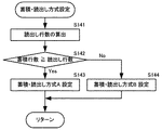
図8のステップS143では、蓄積・読出し方式Aを設定する。蓄積・読出し方式Aとは、図3で説明したような蓄積・読出し方式であり、イメージセンサの読出し対象行からの読出しが終了した後に、該読出し対象行の蓄積を開始するとともに該読出し対象行の次の行の読出しを開始する蓄積読出し方式である。また、ステップS144では、蓄積・読出し方式Bを設定する。蓄積・読出し方式Bとは、図4で説明したような蓄積・読出し方式であり、イメージセンサの読出し対象行の蓄積を開始させた後、該読出し対象行から蓄積行数後の行の蓄積を開始するときから該読出し対象行の読出しを行う蓄積読出し方式である。図8のステップS143あるいはステップS144が実行されると、図8のサブルーチンを終了し、図6のステップS150へと進む。 In step S143 in FIG. 8, the storage / readout method A is set. The storage / readout method A is a storage / readout method as described with reference to FIG. 3. After the reading from the read target row of the image sensor is completed, the storage of the read target row is started and the read target row is started. This is an accumulative read method that starts reading the next row. In step S144, storage / readout method B is set. The accumulation / readout method B is an accumulation / readout method as described with reference to FIG. 4. After the accumulation of the read target row of the image sensor is started, the accumulation of the row after the number of accumulated rows from the read target row is performed. This is an accumulation read system in which the read target row is read from the start. When step S143 or step S144 of FIG. 8 is executed, the subroutine of FIG. 8 is terminated, and the process proceeds to step S150 of FIG.
図6のステップS150では、蓄積行数補正の処理が行われる。ステップS150のサブルーチンを図9に示す。図9では、まずステップS151では、蓄積・読出し方式Aが設定されている場合、ステップS152へと進み、蓄積・読出し方式Bが設定されている場合、ステップS153へと進む。 In step S150 in FIG. 6, processing for correcting the number of accumulated rows is performed. The subroutine of step S150 is shown in FIG. In FIG. 9, first, in step S151, if the accumulation / reading method A is set, the process proceeds to step S152. If the accumulation / reading method B is set, the process proceeds to step S153.
図9のステップS152では、蓄積行数の補正量として、ステップS141で算出された読出し行数にスキップ率を掛けた値が算出される。単位は「行」である。読出し行数は、図5で示した通り2000行である。また、スキップ率は、図6のステップS110で設定されたスキップ単位行数から求めることができる。スキップ率の算出式を以下の式(3)に示す。
スキップ率 = 1 − 1 / スキップ単位行数 ・・・(3)
In step S152 of FIG. 9, a value obtained by multiplying the number of read rows calculated in step S141 by the skip rate is calculated as a correction amount for the number of accumulated rows. The unit is “row”. The number of read lines is 2000 lines as shown in FIG. Further, the skip rate can be obtained from the number of skip unit rows set in step S110 of FIG. The formula for calculating the skip rate is shown in the following formula (3).
Skip rate = 1-1 / number of skip unit lines (3)
前述の通りスキップ単位行数は「4」である。スキップ率は「3/4」となる。よって、ステップS152で設定される補正量は、2000行×(3/4)より、1500行となる。ステップS152が実行された後は、ステップS154へと進む。ステップS154では、蓄積行数に補正量を加算し、蓄積行数を更新する。例えば、図7のステップS132で算出された蓄積行数を2000行とすると、前述の補正量1500行を加算し、得られる補正後の蓄積行数は3500行となる。 As described above, the number of skip unit lines is “4”. The skip rate is “3/4”. Therefore, the correction amount set in step S152 is 1500 lines from 2000 lines × (3/4). After step S152 is executed, the process proceeds to step S154. In step S154, the correction amount is added to the accumulated row number, and the accumulated row number is updated. For example, if the number of accumulated rows calculated in step S132 in FIG. 7 is 2000, the above-described correction amount of 1500 rows is added, and the number of accumulated rows obtained after correction is 3500.
図9のステップS153では、ステップS132で算出された蓄積行数を読出し率で割った値が算出され、補正された蓄積行数として更新される。読出し率は、以下に示す式(4)または式(5)から求めることができる。本実施例の説明で用いてきたスキップ単位行数が「4」であるとき、読出し率は「1/4」となる。
読出し率 = 1 / スキップ単位行数 ・・・(4)
読出し率 = 1 − スキップ率 ・・・(5)
In step S153 in FIG. 9, a value obtained by dividing the number of accumulated rows calculated in step S132 by the read rate is calculated and updated as the corrected number of accumulated rows. The read rate can be obtained from the following formula (4) or formula (5). When the number of skip unit rows used in the description of this embodiment is “4”, the read rate is “1/4”.
Read rate = 1 / number of skip unit lines (4)
Read rate = 1-Skip rate (5)
図9のステップS153で算出される蓄積行数の単位はステップS152と同様の「行」である。蓄積・読出し方式Bとなる条件は、蓄積行数が2000行未満の場合である。これを満たす例として、蓄積行数が300行である場合、読出し率「1/4」で除算すると、補正後の蓄積行数は1200行が得られる。図9のステップS153あるいはS154が実行されると、ステップS155へと進む。 The unit of the number of accumulated rows calculated in step S153 in FIG. 9 is “row” as in step S152. The condition for storage / readout method B is when the number of storage lines is less than 2000 lines. As an example satisfying this, when the number of accumulated rows is 300, and dividing by the read rate “1/4”, the number of accumulated rows after correction is 1200. When step S153 or S154 in FIG. 9 is executed, the process proceeds to step S155.
図9のステップS155では、蓄積行数のマスク処理が行われる。撮影画面で一様な露光時間を得るためには、様々なスキップ設定値に対し、読出し対象行のすべての行において、蓄積時間を同一にする必要がある。すなわち、イメージセンサ101の各行において、蓄積行数が同じでかつ、実時間としての蓄積時間が同じである必要がある。これらを満たすためには、補正後の蓄積行数がスキップ単位行数の整数倍であることが必要となる。補正後の蓄積行数がスキップ単位行数の整数倍ではない場合、イメージセンサ101の特定の行で余計な時間分、蓄積が行われる場合がある。そこで、補正後の蓄積行数をスキップ単位行数の整数倍にマスクする。例えば、図9のステップS153で算出された補正後の蓄積行数1203行の場合、スキップ単位行数「4」の整数倍ではないため、ステップS155でマクス処理を適用すると、補正後の蓄積行数は1200行となる。本実施例ではステップS153で算出された補正後の蓄積行数1200行であるのでもともとスキップ単位行数「4」の整数倍であり、ステップS155の処理を適用した結果は1200行となり変わらない。タイミングチャートを用いた詳細な説明は、図6のステップS160で後述する。 In step S155 in FIG. 9, the number of accumulated rows is masked. In order to obtain a uniform exposure time on the photographing screen, it is necessary to make the accumulation time the same for all the read target rows for various skip setting values. That is, in each row of the image sensor 101, it is necessary that the number of accumulation rows is the same and the accumulation time as the real time is the same. In order to satisfy these requirements, it is necessary that the number of accumulated rows after correction is an integral multiple of the number of skip unit rows. If the number of accumulated rows after correction is not an integral multiple of the number of skip unit rows, accumulation may be performed for an extra time in a specific row of the image sensor 101. Therefore, the corrected number of accumulated rows is masked to an integral multiple of the number of skip unit rows. For example, in the case of 1203 storage rows after correction calculated in step S153 in FIG. 9, it is not an integer multiple of the skip unit row count “4”. The number is 1200 lines. In the present embodiment, the corrected accumulated row number calculated in step S153 is an integer multiple of the skip unit row number “4”, and the result of applying the process in step S155 is 1200 rows, which is unchanged. Detailed description using the timing chart will be described later in step S160 of FIG.
なお、マスクする値は、スキップ単位行数の整数倍が望ましいが、イメージセンサ101を制御するためのオーバーヘッド処理時間を考慮する場合は、例えばマスク値を整数倍+1などとしても良い。本発明を適用する場合に、イメージセンサ101の仕様に合わせて、ステップS155でマスクされる値は任意の値で良い。図9のステップS155が実行されると、図9のサブルーチンを終了し、図6のステップS160へ進む。 The masking value is preferably an integer multiple of the number of skip unit rows. However, when the overhead processing time for controlling the image sensor 101 is taken into consideration, the mask value may be an integer multiple + 1, for example. When the present invention is applied, the value masked in step S155 may be any value according to the specifications of the image sensor 101. When step S155 of FIG. 9 is executed, the subroutine of FIG. 9 is terminated, and the process proceeds to step S160 of FIG.
図6のステップS160では蓄積・読出し処理が行われる。ステップS160のサブルーチンを図10に示す。図10では、ステップS161から順番に処理が実行される。図10のステップS161では、図9のステップS151と同様に、ステップS143あるいはS144で設定された蓄積・読出し方式を評価する。蓄積・読出し方式Aが設定されている場合、ステップS162へと進む。一方、蓄積・読出し方式Bが設定されている場合、ステップS163へと進む。 In step S160 of FIG. 6, accumulation / reading processing is performed. The subroutine of step S160 is shown in FIG. In FIG. 10, the processing is executed in order from step S161. In step S161 in FIG. 10, the storage / readout method set in step S143 or S144 is evaluated in the same manner as in step S151 in FIG. If the storage / readout method A is set, the process proceeds to step S162. On the other hand, if the storage / readout method B is set, the process proceeds to step S163.
図10のステップS162について説明する。ステップS162では、蓄積・読出し方式Aの撮像処理が実行される。蓄積・読出し方式Aの撮像処理について、図11を用いて説明する。 Step S162 in FIG. 10 will be described. In step S162, the storage / readout method A imaging process is executed. The imaging process of the storage / readout method A will be described with reference to FIG.
図11では、図3と同様に、垂直回路1011に制御線ChargeResetとReadResetおよびLineShiftが接続され、上部にタイミングチャートを示している。図10のステップS162すなわち図11では2000行で構成された例のイメージセンサ101の撮像制御の例について説明する。ここでは、図6のステップS110で設定されたスキップ単位行数「4」と、図9のステップS155で算出された蓄積行数3500行という設定内容に基づいて説明する。
In FIG. 11, similarly to FIG. 3, control lines ChargeReset, ReadReset, and LineShift are connected to the
図11では、まず時間p01で制御線ReadResetとLineShiftにワンショットパルスを入力することで、イメージセンサ101の第1行目の読出しを開始している。そして、時間p01における制御線LineShiftワンショットパルスの入力後ただちに、不図示の時間p02、p03、p04において、制御線LineShiftにワンショットパルスを連続的に入力している。時間p02においては、制御線ChargeResetに対してもワンショットパルスが入力されている。 In FIG. 11, reading of the first row of the image sensor 101 is started by first inputting a one-shot pulse to the control lines ReadReset and LineShift at time p01. Immediately after the input of the control line LineShift one-shot pulse at time p01, the one-shot pulse is continuously input to the control line LineShift at times p02, p03, and p04 (not shown). At time p02, a one-shot pulse is also input to the control line ChargeReset.
図3の例では時間p01における制御線LineShiftパルスの入力後、第1行目の画素信号の読出しを行っていることの説明をした。図11の時間p01からp04まででは、第1行目から第3行目の読出しをすることなく、第4行目への読出し選択へ移行していることとなる。すなわち、第1行目から第3行目までのスキップを行っている。p04における制御線LineShiftパルスの入力後、イメージセンサ101の第4行目の読出しを開始している。 In the example of FIG. 3, it has been described that the pixel signal in the first row is read after the input of the control line LineShift pulse at time p01. From time p01 to p04 in FIG. 11, the process shifts to the reading selection to the fourth line without reading from the first line to the third line. That is, skipping from the first line to the third line is performed. After input of the control line LineShift pulse at p04, reading of the fourth row of the image sensor 101 is started.
ここでは、図3と同様に不図示の水平回路1012の制御線TransferH、Hpulseを用いて、第4行目の画素信号の読出しを行っている。図3での説明と同様に、画素信号の読出し時には、図1のADC103によって制御線Hpulse に同期したAD変換がなされる。第4行目の画素信号の読出しが終了すると、次に時間p05にて時間p01と同様に、制御線LineShiftへのワンショットパルスが入力される。その直後に時間p06からp08までにかけて、時間p02からp04と同様に、制御線LineShiftへのワンショットパルス入力が連続的に行われ、第8行目の読出しが行われる。このようにして、図11では、イメージセンサ101の4行単位でのスキップおよび読出しを行っている。
Here, as in FIG. 3, the pixel signals in the fourth row are read using the control lines TransferH and Hpulse of the horizontal circuit 1012 (not shown). Similar to the description in FIG. 3, when the pixel signal is read, the
図11で示すTReadlineは、1行分の画素信号の読出しに要する時間である。図11では、時間p01からp04までの時間は十分短く、上述の4行単位のスキップおよび読出し時間を合わせた時間が図3のTReadlineと等しい。これらを一般化し、n行の読出し行数に対し、時間p0n-3およびp0nまでは、スキップ単位行数-1行(=3行)分のスキップを行い、1行分を読み出している。本実施例の例では、2000行で構成されたイメージセンサ101を用いているため、n = 2000となる。n以降の時間では、図3と同様にTReadlineの間隔で制御線LineShiftにパルスを入力していく。n以降の時間で、一定のTReadlineの間隔で制御線LineShiftにパルスを出力し続けるのは、この間に蓄積を継続している行は制御線LineShiftのパルスのカウント数で時間を管理しているため、一定間隔のパルスを出力し続ける必要があるためである。そして、時間p0endまで制御線LineShiftにパルスを入力すると、時間p11以降で前述と同様に、4行単位でのスキップ処理および読出し処理が行われる。なお、時間p0endのendは蓄積行数であり、例えば、補正後の蓄積行数が3500行である場合、end = 3500 となる。制御線LineShiftへのワンショットパルスをカウントしていき、蓄積行数分カウントすると、イメージセンサ101にその時間分の蓄積がされることとなる。 TReadline shown in FIG. 11 is the time required to read out pixel signals for one row. In FIG. 11, the time from the time p01 to the time p04 is sufficiently short, and the combined time of skipping and reading time in units of four lines is equal to TReadline in FIG. These are generalized, and skipping is performed for the number of skip unit lines minus 1 line (= 3 lines) until time p0n-3 and p0n with respect to the number of read lines of n lines, and one line is read out. In the example of the present embodiment, since the image sensor 101 configured with 2000 rows is used, n = 2000. At time after n, pulses are input to the control line LineShift at intervals of TReadline as in FIG. In the time after n, the pulse is continuously output to the control line LineShift at a constant TReadline interval, because the line that continues to accumulate during this time is managed by the pulse count of the control line LineShift. This is because it is necessary to continue outputting pulses at regular intervals. When a pulse is input to the control line LineShift until time p0end, skip processing and reading processing in units of four lines are performed after time p11, as described above. The end of time p0end is the number of accumulated rows. For example, when the number of accumulated rows after correction is 3500, end = 3500. When one-shot pulses to the control line LineShift are counted and counted for the number of accumulated rows, the image sensor 101 accumulates for that time.
図11において、2000行分の画素信号の読出し時間Tread_A1は、前述の通り、4行単位のスキップおよび読出し処理が行われるため、図3で示したTread_Aの4分の1の時間、すなわち500行分の読出し時間となっている。読出し行数が4分の1となったことによって、各行への蓄積行数が1500行分短くなってしまう。具体的には、図3では、時間p0nにおいて、蓄積行数2000行分(入力された蓄積時間)が確保されていたが、図11では、p0nの時間において、第1行目は500行分の蓄積行数となっている。言い換えると、時間p0nにおいて、制御線LineShiftパルスは全行数の2000回カウントされているが、実時間としてはスキップ読出ししているため、TReadline×500、が経過していることになる。従って、時間p0nから、実時間でTReadline×500の時間さらに蓄積する必要がある。そこで、図9のステップS154で補正されたように、時間p0endまでの残り蓄積行数1500行分の時間を追加で蓄積させる。すなわち、図3の蓄積時間Tcharge_Aと図11の蓄積時間Tcharge_A1とが実時間で同等となるように撮像制御している。すなわち、読出し対象範囲内のスキップ読出しで読み出されるべき行を一定時間間隔で読出すために、スキップする1500行分に対しては無視できる程度の短時間でLineShiftパルスが入力される。従って、同じ制御線LineShiftパルスのカウントで管理する蓄積時間については、スキップされた1500行分に対応する時間(TReadline×1500)だけ蓄積行数(蓄積時間)を補正する必要があり、この補正された蓄積行数をステップS154で演算している。この補正により、スキップ読出しの条件によって、蓄積・読出し方式Aにおける実質的な蓄積時間が影響を受けて変更されることはなくなる。さらに、図9のステップS155で行われた蓄積行数のマスク処理により、イメージセンサ101の全行数の蓄積時間が同等となっている。これは、イメージセンサ101の蓄積開始タイミングと読出しタイミングがすべてスキップ単位による各開始タイミングで対称性を持たせているためである。 In FIG. 11, the pixel signal readout time Tread_A1 for 2000 rows is skipped and read out in units of 4 rows as described above. Therefore, the time is a quarter of Tread_A shown in FIG. The readout time is minutes. When the number of read lines is reduced to a quarter, the number of accumulated lines in each line is shortened by 1500 lines. Specifically, in FIG. 3, the number of accumulated rows of 2000 (input storage time) is secured at time p0n, but in FIG. 11, the first row is worth 500 rows at time p0n. The accumulated number of rows. In other words, at the time p0n, the control line LineShift pulse is counted 2000 times of the total number of rows, but since it is skip-reading in real time, TReadline × 500 has elapsed. Therefore, it is necessary to further accumulate TReadline × 500 time in real time from time p0n. Therefore, as corrected in step S154 in FIG. 9, the time corresponding to 1500 remaining remaining lines until time p0end is additionally accumulated. That is, the imaging control is performed so that the accumulation time Tcharge_A in FIG. 3 and the accumulation time Tcharge_A1 in FIG. 11 are equal in real time. That is, in order to read out rows to be read by skip reading within the read target range at regular time intervals, the LineShift pulse is input in a short time that can be ignored for the 1500 rows to be skipped. Therefore, for the accumulation time managed by the count of the same control line LineShift pulse, it is necessary to correct the number of accumulation lines (accumulation time) by the time corresponding to the skipped 1500 lines (TReadline × 1500). The number of accumulated rows is calculated in step S154. By this correction, the substantial accumulation time in the accumulation / readout method A is not affected and changed by the skip reading condition. Furthermore, the accumulation times of all the lines of the image sensor 101 are equalized by the masking process of the number of accumulated lines performed in step S155 of FIG. This is because the accumulation start timing and read timing of the image sensor 101 are all symmetrical at each start timing in skip units.
このように図11では、図9で示したような蓄積行数に補正量を加え、さらにスキップ単位行数によるマスク処理を適用することで、イメージセンサ101の各行の蓄積時間を同等としている。そのため、イメージセンサ101の行間における蓄積時間の差異を少なくすることができ、露光ムラなどの発生を抑制することが可能となる。 In this way, in FIG. 11, the accumulation time of each row of the image sensor 101 is made equal by adding a correction amount to the number of accumulated rows as shown in FIG. 9 and applying a mask process based on the number of skip unit rows. Therefore, the difference in accumulation time between the rows of the image sensor 101 can be reduced, and the occurrence of uneven exposure can be suppressed.
図10のフローチャートの説明に戻る。ステップS163では、ステップS163では、蓄積・読出し方式Bの撮像処理が実行される。蓄積・読出し方式Bの撮像処理について、図12を用いて説明する。 Returning to the flowchart of FIG. In step S163, in step S163, the image capturing process of the storage / readout method B is executed. The image pickup processing of the storage / readout method B will be described with reference to FIG.
図12では図11と同様に、垂直回路1011に制御線ChargeResetとReadResetおよびLineShiftが接続され、上部にタイミングチャートを示している。図6のステップS110で設定されたスキップ単位行数「4」と、図9のステップS155で算出された蓄積行数1200行という設定内容に基づいて、2000行で構成されたイメージセンサ101の撮像制御の例について説明する。また、図11での蓄積・読出し方式Aでの説明と同様に、4k行(kは自然数)を読み出し、かつ4k-1行、4k-2行、4k-3行をスキップするものとして説明する。
In FIG. 12, similarly to FIG. 11, control lines ChargeReset, ReadReset, and LineShift are connected to the
図12では、まず、時間p01で制御線ChargeResetおよびLineShiftにワンショットパルスを入力することで、イメージセンサ101の第1行目の蓄積を開始している。そして、時間p01における制御線LineShiftにワンショットパルスの入力後、ただちに、不図示の時間p02、p03、p04において、制御線LineShiftに連続的にワンショットパルスを入力している。ここでは、イメージセンサ101の第2行目から第4行目の蓄積を開始している。図11の時間p01からp04までの間隔時間と同様に、Treadlineの時間よりも十分短い。時間p04からTreadlineの時間経過後、すなわち時間p05にて、制御線LineShiftへのワンショットパルス入力が行われる。時間p05の直後は、時間p02からp04と同様に、時間p06からp08までにかけて、制御線LineShiftへのワンショットパルスが連続的に入力される。時間p09以降も同様にして制御線LineShiftへワンショットパルスを入力していく。そして、時間p01+Tcで、制御線ReadResetおよびLineShiftへそれぞれワンショットパルスが入力されると、イメージセンサ101からの画像信号読出しが開始される。Tcは図9のステップS153で算出された蓄積行数を示しており1200行となる。すなわち、イメージセンサの所定の読出し対象行の蓄積を開始させた後、蓄積行数後(カウント数後)の行の蓄積を開始するときから該所定の読出し対象行の読出しを行う。 In FIG. 12, first, accumulation of the first row of the image sensor 101 is started by inputting a one-shot pulse to the control lines ChargeReset and LineShift at time p01. Immediately after the one-shot pulse is input to the control line LineShift at time p01, the one-shot pulse is continuously input to the control line LineShift at times p02, p03, and p04 (not shown). Here, accumulation of the second row to the fourth row of the image sensor 101 is started. Similar to the interval time from time p01 to p04 in FIG. 11, it is sufficiently shorter than the Treadline time. One-shot pulse input to the control line LineShift is performed after the elapse of Treadline from time p04, that is, at time p05. Immediately after time p05, one-shot pulses are continuously input to the control line LineShift from time p06 to p08 in the same manner as time p02 to p04. Similarly, after the time p09, a one-shot pulse is input to the control line LineShift. When a one-shot pulse is input to the control lines ReadReset and LineShift at time p01 + Tc, image signal reading from the image sensor 101 is started. Tc indicates the number of accumulated rows calculated in step S153 in FIG. 9, and is 1200 rows. That is, after the accumulation of a predetermined readout target row of the image sensor is started, the predetermined readout target row is read from the time when the accumulation of the row after the accumulation row number (after the count number) is started.
時間p01+Tcのタイミングでのワンショットパルスの入力後、ただちに不図示の時間p02+Tc、p03+Tc、p04+Tcのタイミングで制御線LineShiftへワンショットパルスが入力される。これにより、第1行目から第3行目の読出しをすることなく、第4行目への選択へ移行していることとなる。この動作は、図11での説明と同様である。すなわち、第1行目から第3行目までのスキップを行い、時間p04+TcにおけるLineShiftパルスの入力後、イメージセンサ101の第4行目の読出しを開始している。ここでは、図3と同様に不図示の水平回路1012の制御線TransferH、Hpulseを用いて、第4行目の画素信号の読出しを行っている。図3での説明と同様に、画素信号の読出し時には、図1のADC103によってHpulse に同期したAD変換がなされる。以下同様にして、画像信号の読出しを行っていく。
Immediately after the one-shot pulse is input at time p01 + Tc, the one-shot pulse is input to the control line LineShift at times p02 + Tc, p03 + Tc, and p04 + Tc (not shown). As a result, the process shifts to selection to the fourth line without reading from the first line to the third line. This operation is the same as described with reference to FIG. That is, skipping from the first line to the third line is performed, and reading of the fourth line of the image sensor 101 is started after inputting the LineShift pulse at time p04 + Tc. Here, as in FIG. 3, the pixel signals in the fourth row are read using the control lines TransferH and Hpulse of the horizontal circuit 1012 (not shown). Similarly to the description in FIG. 3, when the pixel signal is read, the
図12では、図11と同様に、時間p01+Tcからp04+Tcまでの時間は十分短く、上述の4行単位のスキップおよび読出し時間を合わせた時間が図3のTReadlineと等しい。これらを一般化すると、n行の読出し行数に対し、時間p01からp0n-1+Tcおよびp0n+Tcまでは、3行をスキップし、1行を読み出すというサイクルを繰り返すこととなる。本実施例の例では、図11と同様にイメージセンサ101の行数n=2000となる。 In FIG. 12, similarly to FIG. 11, the time from time p01 + Tc to p04 + Tc is sufficiently short, and the combined time of skipping and reading time in units of four rows is equal to TReadline in FIG. When these are generalized, with respect to the number of read rows of n rows, from time p01 to p0n-1 + Tc and p0n + Tc, a cycle of skipping three rows and reading one row is repeated. In the example of this embodiment, the number of rows n of the image sensor 101 is 2000 as in FIG.
図12において、蓄積時間Tcharge_B1は、蓄積行数に換算するとTcであり1200行である。4行単位のスキップおよび読出し処理により、実時間としての蓄積時間は1/4であるTreadline×300行分の時間となるが、実時間としては、図6のステップS110で入力された蓄積時間と同等となる。すなわち、ユーザが入力した所望の露光レベルと同等の撮影画像が得られることとなる。また、4行単位のスキップおよび読出し処理により、図12のTread_B1は、図3および図4で示したTread_AおよびTread_Bの4分の1の時間、すなわち300行分の読出し時間となっている。蓄積・読出し方式Bにおいては、読出し対象範囲すべての行に対する読出しは蓄積時間内では終わらない。そのため、スキップ読出しが設定されている場合には、蓄積時間を制御するための基準となる制御線LineShiftへのパルスは読出し行を読み出すタイミングでのみTReadlineの間隔で出力され、読出しスキップ行をスキップするタイミングでは、無視できる程度の短い間隔で出力される。従って、スキップ読出しの有無に関わらず一定の蓄積時間を維持するために、読出し率で蓄積行数を補正する必要があり、これをステップS153で演算している。この補正により、スキップ読出しの条件によって、蓄積・読出し方式Bにおける実質的な蓄積時間が影響を受けて変更されることはなくなる。 In FIG. 12, the accumulation time Tcharge_B1 is Tc in terms of the number of accumulated rows, which is 1200 rows. By the skip and read processing in units of four lines, the accumulation time as a real time is 1/4, which is a time corresponding to Treadline × 300 lines. The real time is the accumulation time input in step S110 in FIG. It becomes equivalent. That is, a captured image equivalent to the desired exposure level input by the user is obtained. Further, Tread_B1 in FIG. 12 becomes a quarter time of Tread_A and Tread_B shown in FIGS. 3 and 4, that is, a read time for 300 rows, by the skip and read processing in units of four rows. In the storage / readout method B, reading for all rows in the read target range does not end within the storage time. Therefore, when skip reading is set, the pulse to the control line LineShift, which is a reference for controlling the accumulation time, is output at the interval of TReadline only at the timing of reading out the readout row, and the readout skip row is skipped. The timing is output at an interval that can be ignored. Therefore, in order to maintain a constant accumulation time regardless of whether skip reading is performed or not, it is necessary to correct the number of accumulated rows with the read rate, and this is calculated in step S153. By this correction, the substantial accumulation time in the accumulation / readout method B is not affected and changed by the skip reading condition.
なお、図12に示す蓄積・読出しモードBにおける撮像制御では、時間p01+Tcにおいて、Tc+1行目の蓄積が開始されている。すなわち、ある行の読み出し処理を行う場合、同じ蓄積行数分加算した行の蓄積が開始されている。図11で説明したように、イメージセンサ101の全行蓄積時間を同等とするためには、前述の4行単位の制御線LineShiftへのパルス処理を、第1行目の蓄積開始から最終行までにかけて、一貫して行う必要がある。本実施例のスキップ単位を「4」とした例では、図11での説明と同様に、図9のステップS155で行われた蓄積行数のマスク処理により、蓄積行数が4の倍数となっている。このようにマスク処理をすることによって、イメージセンサ101の蓄積開始タイミングと読出しタイミングがすべてスキップ単位による各開始タイミングで対称性を持たせることができる。その結果、図12においても図11と同様に、イメージセンサ101の各行の蓄積時間が同等となっている。 In the imaging control in the accumulation / readout mode B shown in FIG. 12, accumulation of the Tc + 1th row is started at time p01 + Tc. That is, when performing a reading process of a certain line, accumulation of the line added for the same number of accumulated lines is started. As described with reference to FIG. 11, in order to make the accumulation time of all rows of the image sensor 101 equal, the pulse processing to the control line LineShift in units of four rows is performed from the start of accumulation of the first row to the last row. It must be done consistently. In the example in which the skip unit is “4” in the present embodiment, the number of accumulated rows becomes a multiple of 4 by the mask processing of the number of accumulated rows performed in step S155 of FIG. ing. By performing mask processing in this way, the accumulation start timing and the read timing of the image sensor 101 can all be symmetrical at each start timing in skip units. As a result, in FIG. 12, as in FIG. 11, the accumulation time of each row of the image sensor 101 is equal.
このように、本実施例では、イメージセンサ101のおよび1行あたりの読出し時間に基づき、蓄積行数を算出した。そして、図6のステップS110で設定されたスキップ設定に基づき蓄積行数を図6のステップS150で補正した後に、イメージセンサ101 の撮像制御を行う。特に、図9のステップS155で示したマスク処理を加えることで、スキップ処理を行った場合でも、イメージセンサ101の全行において蓄積時間が同等とすることができる。これらは、前述の2種類の撮像制御方式で個別に蓄積行数を補正する必要があり、それぞれにおける撮像制御例について示した。 As described above, in this embodiment, the number of accumulated rows is calculated based on the readout time of the image sensor 101 and per row. Then, after correcting the number of accumulated rows in step S150 in FIG. 6 based on the skip setting set in step S110 in FIG. 6, the imaging control of the image sensor 101 is performed. In particular, by adding the mask processing shown in step S155 of FIG. 9, even when skip processing is performed, the accumulation time can be made equal in all rows of the image sensor 101. In these cases, it is necessary to individually correct the number of accumulated rows in the above-described two types of imaging control methods, and examples of imaging control in each of them are shown.
なお、本実施例で説明したスキップ単位数や蓄積時間、イメージセンサの画素数については限定されず、様々な設定値あるいは画素数に対して、本発明を適用することができる。また、本実施例では、スキップ単位行数に対し、読み出す行数を1行とした例について説明したが、読み出す行数は1行に限定されない。例えば、モノクロカメラあるいは3枚の撮像素子で構成されるカラーカメラの場合は、本実施例での説明を適用するのが望ましい。一方で、撮像素子が単板であるカラーカメラの場合は、ベイヤ配列について考慮する必要がある。すなわち、複数行にまたがって1色が作られるようなベイヤ配列で構成される撮像素子を用いる場合、スキップ単位に対し、読み出す行数を2行以上としても良い。 Note that the number of skip units, the accumulation time, and the number of pixels of the image sensor described in this embodiment are not limited, and the present invention can be applied to various setting values or the number of pixels. In the present embodiment, the example in which the number of rows to be read is one row with respect to the number of skip unit rows has been described, but the number of rows to be read is not limited to one. For example, in the case of a monochrome camera or a color camera composed of three image sensors, it is desirable to apply the description in this embodiment. On the other hand, in the case of a color camera in which the image sensor is a single plate, it is necessary to consider the Bayer arrangement. That is, in the case of using an image pickup device configured with a Bayer array in which one color is created across a plurality of rows, the number of rows to be read may be two or more for a skip unit.
また、一般的なイメージセンサでは、第1行目から数十行分は、光電変換素子の無い領域や、遮光領域が構成されている。これら2種類の領域における画素信号に基づいて、有効画素領域の黒基準レベルを補正することは一般的に一般的行われる。蓄積・読出し方式Bでスキップ処理を行う場合、蓄積開始と読出し開始タイミングの対称性を保つため、第1行目から最終行までにかけて、スキップ単位行数でのスキップおよび読出し処理を行うことが望ましい。一方で、蓄積・読出し方式Aでスキップ処理を行う場合は、上記2領域の読出し時にはスキップせず、有効画素領域のみスキップ処理を行っても良い。 Further, in a general image sensor, an area without photoelectric conversion elements and a light shielding area are configured for several tens of lines from the first line. It is generally performed to correct the black reference level of the effective pixel region based on the pixel signals in these two types of regions. When performing skip processing in the accumulation / read method B, it is desirable to perform skip and read processing in the number of skip unit rows from the first row to the last row in order to maintain the symmetry between the accumulation start and read start timing. . On the other hand, when skip processing is performed in the storage / readout method A, skipping may be performed only on the effective pixel region without skipping when reading the two regions.
以上、本実施例によれば、スキップ処理が伴う撮影において、撮影画像の各行間の露光ムラを低減することが可能である。 As described above, according to the present embodiment, it is possible to reduce the exposure unevenness between the rows of the photographed image in photographing involving the skip process.
実施例1では、イメージセンサ101の全画面に対し、所定のスキップ率で撮像制御を行う例について説明してきた。本実施例では、イメージセンサ101のうち、一部の関心領域を読出しの対象領域として抽出し、それ以外の領域を読み飛ばすような撮像制御について説明する。実施例1の図12で説明したように、蓄積・読出し方式Bでは蓄積時間が読出し時間よりも短い条件であり、読出し行に蓄積行数を加算した行が蓄積開始となる行である。関心領域が複数である場合、関心領域以外の領域をスキップすると、関心領域(読出し領域)の蓄積時間が削減される場合がある。そのため、関心領域の行間で蓄積時間が異なり、関心領域内で輝度ムラが発生する場合がある。本実施例ではこのような撮影条件において、関心領域すなわち読出領域が複数存在する場合でも、各行間の輝度ムラを低減する実施例について説明する。 In the first embodiment, an example in which imaging control is performed with a predetermined skip rate on the entire screen of the image sensor 101 has been described. In the present embodiment, a description will be given of imaging control in which a part of a region of interest in the image sensor 101 is extracted as a reading target region and other regions are skipped. As described with reference to FIG. 12 of the first embodiment, in the accumulation / reading method B, the accumulation time is shorter than the read time, and a line obtained by adding the number of accumulated lines to the read line is a line from which accumulation starts. When there are a plurality of regions of interest, skipping regions other than the region of interest may reduce the accumulation time of the region of interest (readout region). For this reason, the accumulation time differs between the rows of the region of interest, and uneven brightness may occur in the region of interest. In this embodiment, an embodiment will be described in which luminance unevenness between rows is reduced even when there are a plurality of regions of interest, that is, readout regions under such shooting conditions.
本実施例における撮像装置の構成およびイメージセンサ101の構成は図1と図2に示されている。これらの構成は、実施例1と同様であるため、説明を省略する。 The configuration of the imaging apparatus and the configuration of the image sensor 101 in this embodiment are shown in FIGS. Since these configurations are the same as those of the first embodiment, description thereof is omitted.
本実施例では、イメージセンサ101のうち、上下方向に2つの関心領域が設定されるような撮像例について説明する。図13にイメージセンサ101が2000行の撮像素子で構成されている例を示す。本実施例では、図13の斜線部の2つの関心領域AreaAおよびAreaBを選択して読み出す場合において、行間における露光時間を同等とする例について説明する。本実施例において撮像装置100が行う処理のフローチャートを図14に示す。撮像装置100に電源が投入されると、図14に示すステップS210から順番に処理を実行していく。
In the present embodiment, an imaging example in which two regions of interest are set in the vertical direction in the image sensor 101 will be described. FIG. 13 shows an example in which the image sensor 101 is composed of 2000 rows of image sensors. In the present embodiment, an example will be described in which the exposure times between rows are equal when the two regions of interest AreaA and AreaB in the shaded area in FIG. 13 are selected and read. FIG. 14 shows a flowchart of processing performed by the
まず、図14のフローチャートのステップS210では読出し領域設定の入力を行う。ここでは、図1の読出し条件設定手段300によって、読出し条件入力部107を通じて入力される。本実施例では、読出し領域として図13の斜線部分の領域を読み出すため、各読出し領域の座標情報となる開始座標(X, Y)と終了座標(X,Y)を以下のように入力する。
・AreaA:開始座標 (501, 201)、終了座標 (2500 400)
・AreaB:開始座標 (501,1501)、終了座標 (2500, 1700)
First, in step S210 of the flowchart of FIG. 14, a reading area setting is input. Here, it is input through the read
-AreaA: Start coordinate (501, 201), End coordinate (2500 400)
-AreaB: Start coordinate (501,1501), End coordinate (2500, 1700)
読出し設定値は図1の読出し条件入力部107で保持され、蓄積制御部109に入力される。図14のステップS210が実行されると、次にステップS120へ進む。
The read set value is held by the read
図14のステップS120では、実施例1と同様にシャッター速度に対応する蓄積時間を入力する。ステップS120が実行されると、ステップS220へと進む。 In step S120 of FIG. 14, the accumulation time corresponding to the shutter speed is input as in the first embodiment. When step S120 is executed, the process proceeds to step S220.
図14のステップS220では、蓄積時間から蓄積行数への変換演算が行われる。ステップS220のサブルーチンを図15に示す。 In step S220 in FIG. 14, a conversion operation from the accumulation time to the number of accumulated rows is performed. The subroutine of step S220 is shown in FIG.
図15のサブルーチンでは、ステップS221から順番に処理が実行される。まず、ステップS221において、読出し領域の最小・最大座標が算出される。前述のAreaA、AreaBの各座標からXおよびYの最小、最大座標を求める。図16に示すように、AreaA、AreaBを含むAreaCとして1つの領域と見立てると、以下の最小座標および最大座標を得る。本実施例では、AreaAからAreaBにかけて1500行を、スキップを含めた読出し対象領域とする。
・AreaC:最小座標(501,201)、最大座標(2500, 1700)
In the subroutine of FIG. 15, processing is executed in order from step S221. First, in step S221, the minimum and maximum coordinates of the reading area are calculated. Find the minimum and maximum coordinates of X and Y from the above-mentioned coordinates of AreaA and AreaB. As shown in FIG. 16, assuming that AreaC includes AreaA and AreaB as one area, the following minimum and maximum coordinates are obtained. In this embodiment, 1500 rows from Area A to Area B are set as read target areas including skips.
-AreaC: Minimum coordinate (501,201), maximum coordinate (2500, 1700)
次に図15のステップS222へと進み、1行あたりの読出し時間が算出される。まず、前述のAreaCの幅を求めると2000画素となる。この幅画素数を読み出すための時間を1行あたりの読出し時間とする。実施例1と同様に、1画素あたりの読出し時間と前述のAreaCの幅画素数に基づき、1行を読出しのためのオーバーヘッド時間などを考慮して算出する。次にステップS223へと進み、ステップS120で入力された蓄積時間を、ステップS222で算出した1行あたりの読出し時間で除算することにより、蓄積行数を算出する。 Next, the process proceeds to step S222 in FIG. 15, and the read time per line is calculated. First, if the width of the above-mentioned AreaC is obtained, it becomes 2000 pixels. The time for reading out the width pixel number is set as a reading time per line. In the same manner as in the first embodiment, one row is calculated in consideration of the overhead time for reading out and the like based on the reading time per pixel and the above-mentioned AreaC width pixel number. Next, proceeding to step S223, the number of accumulated rows is calculated by dividing the accumulation time input at step S120 by the read time per row calculated at step S222.
なお、実施例1で算出された1行あたりの読出し時間TReadlineは、1行の画素データすべてを読み出すことを前提としている。一方で、本実施例では、図13および図16に示す通り、対象としている領域の横画素数は2000画素としており、1行全体3000画素の2/3の画素数となる。前述の通り、制御線Hpulseによる画素信号の読出し時間は、1行あたりの読出し画素数に依存するため、実施例1と比較し、約2/3の読出し時間となる。そのため、図7のステップS132で算出される蓄積行数は、実施例1と比較し、約1.5倍の蓄積行数が算出されることとなる。このように、ステップS210で入力される読出し領域のサイズにより、1行あたりの画素信号の読出し時間が変化することとなる。 Note that the readout time TReadline per row calculated in the first embodiment is based on the premise that all pixel data in one row is read out. On the other hand, in this embodiment, as shown in FIGS. 13 and 16, the number of horizontal pixels in the target region is 2000 pixels, which is 2/3 of 3000 pixels in the entire row. As described above, the readout time of the pixel signal by the control line Hpulse depends on the number of readout pixels per row, so that the readout time is about 2/3 compared with the first embodiment. Therefore, the number of accumulated rows calculated in step S132 of FIG. 7 is approximately 1.5 times the number of accumulated rows compared to the first embodiment. As described above, the readout time of the pixel signals per row changes depending on the size of the readout region input in step S210.
図15のフローチャートの説明に戻る。ステップS223が実行されると、図15のサブルーチンを終了し、図14のステップS140へと進む。 Returning to the flowchart of FIG. When step S223 is executed, the subroutine of FIG. 15 is terminated, and the process proceeds to step S140 of FIG.
図14のステップS140では、実施例1と同様に蓄積方式が設定される。本実施例における読出し行数は、図16に示す通り1500行である。そのため、ステップS140のサブルーチンである図8のステップS142で行われる判定式では、読出し行数1500行との大小比較結果に基づいて、蓄積・読出し方式AもしくはBが選択されることとなる。ステップS140が実行されると、ステップS300に進む。 In step S140 of FIG. 14, the storage method is set as in the first embodiment. In this embodiment, the number of read rows is 1500 as shown in FIG. Therefore, in the determination formula performed in step S142 of FIG. 8, which is a subroutine of step S140, the storage / readout method A or B is selected based on the size comparison result with the number of read rows of 1500. When step S140 is executed, the process proceeds to step S300.
図14のステップS300では、イメージセンサ101の撮像制御が行われる。ステップS300では、図6のステップS160と同様に蓄積行数と読出し行数の大小比較結果に基づいて、蓄積・読出し方式AもしくはBが実行される。ステップS300のサブルーチンを図17に示す。 In step S300 of FIG. 14, the imaging control of the image sensor 101 is performed. In step S300, the storage / readout method A or B is executed based on the result of comparing the number of stored rows and the number of read rows as in step S160 of FIG. The subroutine of step S300 is shown in FIG.
図17では、まずステップS310にて蓄積・読出し方式を判定する。図10のステップS161と同様に、図14のステップS140で設定された蓄積方式に従い、蓄積・読出し方式AであればステップS320へ、蓄積・読出し方式BであればステップS330へと進む。 In FIG. 17, the storage / readout method is first determined in step S310. Similar to step S161 in FIG. 10, according to the accumulation method set in step S140 in FIG. 14, the process proceeds to step S320 if the accumulation / read method A, and proceeds to step S330 if the accumulation / read method B.
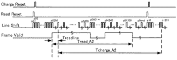
図17のステップS320では、蓄積・読出し方式Aが実行される。ステップS320で実行されるタイミングチャートを図18に示す。 In step S320 of FIG. 17, the storage / readout method A is executed. A timing chart executed in step S320 is shown in FIG.
図18では、p01において制御線LineShiftおよびReadResetへのワンショットパルスが入力され、イメージセンサ101 の第1行目の読出しを開始している。そして、p01の直後にp02において、制御線ChargeResetおよびLineShiftへのワンショットパルスを入力することによって、イメージセンサ101 の第2行目の読出しおよび第1行目の蓄積を開始している。ただし、p01からp0201まで連続的に制御線LineShiftにワンショットパルスを入力していくことで、イメージセンサ101の第1行目から第200行目までをスキップしている。p0201以降、p0400までは、Treadlineの間隔で制御線LineShiftへワンショットパルスを入力していくことでAreaAすなわち第201行目から第400行目までの画素信号が読み出される。ここで、本実施例におけるTreadlineは、図14ステップS220にて説明したように、実施例1におけるTreadlineの間隔時間の2/3の時間となる。
In FIG. 18, one-shot pulses are input to the control lines LineShift and ReadReset at p01, and reading of the first row of the image sensor 101 is started. Immediately after p01, at p02, a one-shot pulse is input to the control lines ChargeReset and LineShift, thereby starting reading of the second row and accumulation of the first row of the image sensor 101. However, the first to 200th rows of the image sensor 101 are skipped by inputting one-shot pulses to the control line LineShift continuously from p01 to p0201. From p0201 to p0400, by inputting one-shot pulses to the control line LineShift at intervals of Treadline, the pixel signals from Area A, that is, from the 201st row to the 400th row are read. Here, Treadline in the present embodiment is 2/3 of the interval time of Treadline in
図18の時間p0401からp01501までは、時間p01からのスキップ処理と同様に、制御線LineShiftへ連続的にワンショットパルスを入力する。時間p01からp0201までのスキップ処理、および時間p401からp01501までのスキップ処理の時間は、Treadlineよりも十分短い。このように第401行目から第1500行目までの読出しをスキップしている。時間p01501以降、p01700までは、Treadlineの間隔で制御線LineShiftへワンショットパルスを入力していくことでAreaBすなわち第1501行目から第1700行目までの画素信号が読み出される。第1700行目までの画素信号が読み出された後は、図14のステップS220で算出された蓄積行数分すなわち時間p0endまでのタイミング時間まで蓄積する。その後、時間p11で制御線ReadResetへのワンショットパルス入力が行われることで蓄積が終了し、時間p11以降、時間p01からの処理と同様の処理が行われることによって画素信号の読出しが行われていく。 From time p0401 to p01501 in FIG. 18, the one-shot pulse is continuously input to the control line LineShift similarly to the skip processing from time p01. The time of the skip process from time p01 to p0201 and the time of the skip process from time p401 to p01501 are sufficiently shorter than Treadline. In this way, reading from the 401st line to the 1500th line is skipped. From time p01501 to time p01700, by inputting one-shot pulses to the control line LineShift at intervals of Treadline, the pixel signals from Area B, that is, the 1501st to 1700th lines are read out. After the pixel signals up to the 1700th row are read out, they are accumulated until the timing time up to the number of accumulated rows calculated in step S220 in FIG. 14, that is, the time p0end. Thereafter, accumulation is completed by inputting a one-shot pulse to the control line ReadReset at time p11, and after time p11, pixel signals are read by performing processing similar to the processing from time p01. Go.
図18のFrameValidがHi状態である期間は、図13および図16のAreaAからAreaBにかけて、すなわちAreaCの画素信号読出し期間である。前述のAreaCの1500行分が読み出される時間を図18のTread_A2で示している。ただし、1500行分の読出し時間がかかるわけではなく、AreaAおよびAreaB以外の領域がスキップされるため、AreaAとAreaBの合計行数400行分の読出し時間となる。 The period in which FrameValid in FIG. 18 is in the Hi state is from Area A to Area B in FIGS. 13 and 16, that is, the area C pixel signal readout period. The time for reading the above-mentioned AreaC for 1500 rows is indicated by Tread_A2 in FIG. However, the reading time for 1500 lines is not required, and areas other than AreaA and AreaB are skipped, so the reading time is 400 lines for the total number of AreaA and AreaB.
図18で示した蓄積・読出し方式Aによるスキップ処理では、制御線ReadResetとChargeResetの差が1行分の差であるため、蓄積開始から読出し開始までの実時間差Tcharg_A2がイメージセンサ101の各行数で同等となっている。すなわち、AreaAやAreaBのように複数の読出し領域を設定し、対象領域以外の領域をスキップしたとしても、イメージセンサ101の各行の蓄積時間は同等とすることができる。これは、対象領域における行間の蓄積開始の時間差をTreadlineとすることで、同領域の読出し開始の行間時間差と同等としているためである。 In the skip processing by the accumulation / readout method A shown in FIG. 18, the difference between the control lines ReadReset and ChargeReset is a difference of one line, so the real time difference Tcharg_A2 from the accumulation start to the read start is the number of lines of the image sensor 101. It is equivalent. That is, even if a plurality of read areas are set like Area A and Area B and areas other than the target area are skipped, the accumulation time of each row of the image sensor 101 can be made equal. This is because the time difference of the accumulation start between the lines in the target area is set to Treadline, which is equivalent to the time difference between the lines at the start of reading in the same area.
図17のフローチャートの説明に戻る。図17のステップS330では、蓄積・読出し方式Bが実行される。蓄積・読出し方式Bによる方式では、制御線ChargeResetによる蓄積開始タイミングと制御線ReadResetによる読出し開始タイミングに蓄積行数分の差がある。また、ローリングシャッターでは、蓄積・読出し方式Bでは読出し中のラインに蓄積行数を加算したラインにおいて蓄積が開始される制約がある。これらを勘案し、蓄積・読出し方式Bでスキップを行う場合、イメージセンサ101の全行数で同等の蓄積時間を保証するために、対象領域に対する蓄積と読出しのスキップ有無を切り替えることが望ましい。 Returning to the flowchart of FIG. In step S330 of FIG. 17, storage / readout method B is executed. In the storage / readout method B, there is a difference corresponding to the number of storage rows between the storage start timing by the control line ChargeReset and the read start timing by the control line ReadReset. In addition, in the rolling shutter, in the accumulation / readout method B, there is a restriction that accumulation is started in a line obtained by adding the number of accumulated rows to the line being read out. Considering these points, when skipping is performed in the storage / readout method B, it is desirable to switch between storage and readout skipping in the target area in order to guarantee the same storage time for all the rows of the image sensor 101.
少なくともAreaAとAreaBで各行の蓄積時間を同等するためには、前述の通り、AreaAとAreaBの読出しと蓄積を行うタイミングでは、制御線LineShiftへのワンショットパルス入力間隔をTreadlineとする必要がある。読出し行と、その時に蓄積が開始される蓄積開始行との関係は、蓄積行数を用いて式(6)のように示すことができる。
・読出し行 = 蓄積開始行 − 蓄積行数 ・・・(6)
In order to at least equalize the storage time of each row in AreaA and AreaB, as described above, the one-shot pulse input interval to the control line LineShift needs to be Treadline at the timing of reading and storing AreaA and AreaB. The relationship between the read line and the accumulation start line at which accumulation starts at that time can be expressed as in equation (6) using the number of accumulation lines.
-Read line = Accumulation start line-Number of accumulation lines ... (6)
また、読出し行と蓄積開始行は、以下の条件式(7)及び(8)を満たす場合はスキップ不可である。
・読出し対象領域開始行 ≦ 読出し行 ≦ 読出し対象領域終了行 ・・・(7)
・読出し対象領域開始行 ≦ 蓄積開始行 ≦ 読出し対象領域終了行 ・・・(8)
Further, the read line and the accumulation start line cannot be skipped if the following conditional expressions (7) and (8) are satisfied.
・ Read target area start line ≤ Read line ≤ Read target area end line ... (7)
・ Read target area start line ≦ Accumulation start line ≦ Read target area end line ・ ・ ・ (8)
(6)、(7)、(8)式を同時に満たすように、スキップ有無を決定することにより、関心領域(読出し領域)内の各行の露出(蓄積時間)は一定に維持され、画質の低下を低減することができる。この具体的な例について、蓄積行数が100行である例について図19のタイミングチャートを用いて説明する。この蓄積行数100行については、図14のステップS220で設定された蓄積行数と仮定する。
By determining whether or not to skip so that expressions (6), (7), and (8) are satisfied at the same time, the exposure (accumulation time) of each line in the region of interest (readout region) is maintained constant, and the image quality deteriorates. Can be reduced. As a specific example, an example in which the number of accumulated rows is 100 will be described with reference to the timing chart of FIG. The number of accumulated
図19ではp01において制御線LineShiftおよびChargeResetへのワンショットパルスが入力され、イメージセンサ101の第1行目の蓄積を開始している。そして、時間p0201すなわち第201行目まで制御線LineShiftへワンショットパルスを連続的に入力することで、第1行目から第200行目までの蓄積を連続的に開始させている。第1行目から第200行目までは、式(8)の観点から蓄積開始のスキップ動作を行って良い。なお、p0101の時間では制御線ReadResetへのワンショットパルス入力が行われているため、第1行目から第100行目までの読出しがスキップされていることとなる。 In FIG. 19, one-shot pulses are input to the control lines LineShift and ChargeReset at p01, and accumulation of the first row of the image sensor 101 is started. Then, the one-shot pulse is continuously input to the control line LineShift until the time p0201, that is, the 201st row, so that the accumulation from the 1st row to the 200th row is started continuously. From the first line to the 200th line, an accumulation start skip operation may be performed from the viewpoint of equation (8). Note that since the one-shot pulse input to the control line ReadReset is performed at the time of p0101, reading from the first row to the 100th row is skipped.
図19の時間p0201からp0501までの間にTreadlineの時間間隔で制御線LineShiftへワンショットパルスを入力する。このとき、第201行目から第501行目までは、各行は制御線LineShiftのパルスの時間差で蓄積が開始されている。また同時に、式(6)より、第101行目から第400行目までがスキップされることなく画素信号が読み出されている。この間AreaAの100行分前から画素信号が読み出されていることとなる。 One-shot pulses are input to the control line LineShift at time intervals of Treadline between times p0201 and p0501 in FIG. At this time, from the 201st line to the 501st line, accumulation of each line is started with a time difference of pulses of the control line LineShift. At the same time, the pixel signal is read out from the 101st row to the 400th row without skipping from the equation (6). During this time, pixel signals are read from 100 lines before AreaA.
図19の時間p0501からp01501までの間は、制御線LineShiftへワンショットパルスを連続的に入力する。これにより、第501行目から第1500行目までの蓄積開始を連続的に行うとともに、第401行目から第1400行目までの読出しがスキップされている。この間、AreaA、AreaB以外の領域の読出しのため、スキップしても影響しない。 During the period from time p0501 to p01501 in FIG. 19, one-shot pulses are continuously input to the control line LineShift. As a result, accumulation from the 501st line to the 1500th line is continuously started, and reading from the 401st line to the 1400th line is skipped. During this time, the area other than AreaA and AreaB is read, so skipping has no effect.
同様にして、図19の時間p1501からp1801までの間にTreadlineの時間間隔で制御線LineShiftへワンショットパルスを入力する。このとき、第1501行目から第1801行目までは、各行は制御線LineShiftのパルスの時間差で蓄積が開始されている。また同時に、式(6)より、第1401行目から第1700行目までがスキップされることなく画素信号が読み出されている。この間AreaBの100行分前から画素信号が読み出されていることとなる。図19の時間p01801では制御線ChargeResetが同時に入力され、次のフレームの蓄積開始としている。 Similarly, a one-shot pulse is input to the control line LineShift at time intervals of Treadline between times p1501 and p1801 in FIG. At this time, from the 1501st line to the 1801st line, accumulation of each line is started at the time difference of the pulse of the control line LineShift. At the same time, from Equation (6), the pixel signals are read without skipping from the 1401st line to the 1700th line. During this time, the pixel signal is read from 100 lines before AreaB. At time p01801 in FIG. 19, the control line ChargeReset is simultaneously input, and accumulation of the next frame is started.
このように、AreaA、AreaBの各行では、蓄積開始から蓄積終了すなわち読出し開始まで、100行分にTreadlineを乗じた長さの蓄積時間となっている。そのため、露光ムラが発生しづらくなっている。 Thus, in each line of AreaA and AreaB, the accumulation time is a length obtained by multiplying 100 lines by Treadline from the accumulation start to the accumulation end, that is, reading start. Therefore, it is difficult for exposure unevenness to occur.
なお、本実施例では、スキップ処理の処理時間は、1行の読出し時間Treadlineよりも十分短い。一方で、読み飛ばす行数が多い場合や、1行あたりの読出し時間Treadlineが短い場合、スキップするための処理時間が無視できない場合がある。その場合は、蓄積行数の算出時に、スキップする処理時間を考慮した上で蓄積行数を算出すると良い。また、本実施例における蓄積・読出し方式Bでは、蓄積行数を100行とする例について説明したが、100行の蓄積行数に限定されない。蓄積・読出し方式Bにおいて、様々な蓄積行数および蓄積時間に対し、式(6)から式(8)を満たす条件でスキップ有無を決定すれば良い。 In this embodiment, the processing time of the skip processing is sufficiently shorter than the read time Treadline for one line. On the other hand, when there are many lines to skip, or when the read time Treadline per line is short, the processing time for skipping may not be ignored. In that case, when calculating the number of accumulated rows, it is preferable to calculate the number of accumulated rows in consideration of the processing time to be skipped. Further, in the storage / readout method B in the present embodiment, an example in which the number of storage rows is 100 has been described, but the number of storage rows is not limited to 100. In the storage / readout method B, the presence / absence of skipping may be determined under conditions satisfying Expressions (6) to (8) for various numbers of storage rows and storage times.
以上、本発明の好ましい実施例について説明したが、本発明はこれらの実施形態に限定されないことはいうまでもなく、その要旨の範囲内で種々の変形及び変更が可能である。また、本稿で述べた実施例を組み合わせて実施しても良い。 As mentioned above, although the preferable Example of this invention was described, it cannot be overemphasized that this invention is not limited to these embodiment, A various deformation | transformation and change are possible within the range of the summary. Further, the embodiments described in this article may be combined.
なお、本発明では、スキップ単位の数として「2」および「4」が設定された例について述べたが、スキップ単位数については任意の数が設定可能である。 In the present invention, an example in which “2” and “4” are set as the number of skip units has been described, but any number of skip units can be set.
また、スキップ単位数に対し、読出し行数は「1」として説明したが、前述の通りカラー撮影を行う場合は、所謂ベイヤ配列を考慮した読出し行数を設定して適用しても良い。また、本発明では最大4つの関心領域が設定された例について述べたが、関心領域の数や座標および領域の大きさについては限定されず、様々な形状や大きさの1以上の関心領域に対して本発明を適用することができる。また、撮影画像に関しては、3000×2000の画素数を例に説明したが、画素数はこれに限定されない。 Further, the number of read rows is described as “1” with respect to the number of skip units, but when performing color imaging as described above, the number of read rows in consideration of a so-called Bayer arrangement may be set and applied. In the present invention, an example in which up to four regions of interest are set has been described. However, the number and coordinates of the regions of interest and the size of the region are not limited, and one or more regions of interest of various shapes and sizes The present invention can be applied to this. Further, regarding the captured image, the number of pixels of 3000 × 2000 has been described as an example, but the number of pixels is not limited to this.
100 撮像装置
101 イメージセンサ
102 センサ制御部(制御手段)
104 アドレスカウンタ(スキップ設定手段)
106 画像信号出力部(画像信号出力手段)
107 読出し条件入力部(読出し条件入力手段)
108 蓄積時間入力部(蓄積時間入力手段)
109 蓄積制御部(制御手段、カウント数設定手段)
300 読出し条件設定手段(読出し条件入力手段)
400 蓄積時間設定手段
100 imaging device
101 Image sensor
102 Sensor control unit (control means)
104 Address counter (skip setting method)
106 Image signal output unit (Image signal output means)
107 Read condition input section (read condition input means)
108 Accumulation time input section (accumulation time input means)
109 Storage control unit (control means, count number setting means)
300 Read condition setting means (read condition input means)
400 Storage time setting method
Claims (12)
前記イメージセンサの読出し単位行あたりの信号読出し時間に基づいて蓄積時間に対応するカウント数を算出するカウント数算出手段と、
前記イメージセンサの読出し行及びスキップ行の単位パターンの行数であるスキップ単位を設定する設定手段と、
前記スキップ単位に基づき、前記イメージセンサで蓄積動作または読出し動作の少なくとも一方に関する処理をスキップする行であるスキップ行を設定するスキップ設定手段と、
前記カウント数および前記スキップ行に基づき、1フレーム内における前記読出し単位行の蓄積時間が一定となるように、前記イメージセンサの蓄積動作及び読出し動作を制御する制御手段と、
を有し、
前記カウント数算出手段は、前記蓄積時間と、読出し領域の単位行あたりの読出し時間と、前記読出し領域と、前記スキップ単位と、に基づいて前記カウント数を設定し、
前記蓄積時間が全ての読出し対象の画素信号を読み出すための読出し時間以上の場合は、前記蓄積時間と前記スキップ単位とに基づいてカウント数を算出し、前記蓄積時間が前記読出し時間より短い場合は、前記蓄積時間と前記読出し領域の読出し対象の行数とに基づいて前記カウント数を算出する、
ことを特徴とする撮像装置。 Rolling shutter type image sensor,
Count number calculating means for calculating a count number corresponding to an accumulation time based on a signal reading time per reading unit row of the image sensor;
Setting means for setting a skip unit that is the number of unit patterns of read lines and skip lines of the image sensor;
Based on the skip unit, skip setting means for setting a skip line that is a line for skipping processing related to at least one of the accumulation operation and the read operation in the image sensor;
Control means for controlling the accumulation operation and readout operation of the image sensor so that the accumulation time of the readout unit row in one frame is constant based on the count number and the skip row;
I have a,
The count number calculating means sets the count number based on the accumulation time, the read time per unit row of the read area, the read area, and the skip unit,
When the accumulation time is equal to or longer than the readout time for reading out all readout target pixel signals, the count number is calculated based on the accumulation time and the skip unit, and when the accumulation time is shorter than the readout time Calculating the number of counts based on the accumulation time and the number of rows to be read in the read area ;
An imaging apparatus characterized by that.
読出し対象領域開始行≦読出し行≦読出し対象領域終了行
読出し対象領域開始行≦蓄積開始行≦読出し対象領域終了行
但し、
読出し行=蓄積開始行−カウント数
を満たす読出し行及び蓄積開始行はスキップ行には設定しない、ことを特徴とする請求項1乃至4のいずれか1項に記載の撮像装置。 The skip setting means, when the accumulation time is shorter than the readout time for reading out all readout target pixel signals,
Read target area start line ≤ Read line ≤ Read target area end line Read target area start line ≤ Accumulation start line ≤ Read target area end line
Read row = accumulation start line - read row and storage start line satisfy the count is not set to the skip line imaging apparatus according to any one of claims 1 to 4, characterized in that.
前記イメージセンサの読出し単位行あたりの信号読出し時間に基づいて蓄積時間に対応するカウント数を算出するカウント数算出手段と、 Count number calculating means for calculating a count number corresponding to an accumulation time based on a signal reading time per reading unit row of the image sensor;
前記イメージセンサの読出し行及びスキップ行の単位パターンの行数であるスキップ単位を設定する設定手段と、 Setting means for setting a skip unit that is the number of unit patterns of read lines and skip lines of the image sensor;
前記スキップ単位に基づき、前記イメージセンサで蓄積動作または読出し動作の少なくとも一方に関する処理をスキップする行であるスキップ行を設定するスキップ設定手段と、 Based on the skip unit, skip setting means for setting a skip line that is a line for skipping processing related to at least one of the accumulation operation and the read operation in the image sensor;
前記カウント数および前記スキップ行に基づき、1フレーム内における前記読出し単位行の蓄積時間が一定となるように、前記イメージセンサの蓄積動作及び読出し動作を制御する制御手段と、を有し、 Control means for controlling the accumulation operation and readout operation of the image sensor so that the accumulation time of the readout unit row in one frame is constant based on the count number and the skip row,
前記カウント数算出手段は、前記蓄積時間と、読出し領域の単位行あたりの読出し時間と、前記読出し領域と、前記スキップ単位と、に基づいて前記カウント数を設定し、 The count number calculating means sets the count number based on the accumulation time, the read time per unit row of the read area, the read area, and the skip unit,
前記蓄積時間が全ての読出し対象の画素信号を読み出すための読出し時間以上の場合は、前記蓄積時間と前記スキップ単位とに基づいてカウント数を算出し、前記蓄積時間が前記読出し時間より短い場合は、前記蓄積時間と前記読出し領域の読出し対象の行数とに基づいて前記カウント数を算出することを特徴とする撮像システム。 When the accumulation time is equal to or longer than the readout time for reading out all readout target pixel signals, the count number is calculated based on the accumulation time and the skip unit, and when the accumulation time is shorter than the readout time The imaging system is characterized in that the count number is calculated based on the accumulation time and the number of rows to be read in the readout area.
読出し対象領域開始行≦読出し行≦読出し対象領域終了行 Read target area start line ≤ Read line ≤ Read target area end line
読出し対象領域開始行≦蓄積開始行≦読出し対象領域終了行 Read target area start line ≤ Accumulation start line ≤ Read target area end line
但し、 However,
読出し行=蓄積開始行−カウント数 Read line = accumulation start line-count number
を満たす読出し行及び蓄積開始行はスキップ行には設定しない、ことを特徴とする請求項7乃至10のいずれか1項に記載の撮像システム。11. The imaging system according to claim 7, wherein a read line and an accumulation start line that satisfy the condition are not set as skip lines.
前記イメージセンサの読出し行及びスキップ行の単位パターンの行数であるスキップ単位を設定するステップと、 Setting a skip unit which is the number of unit patterns of read lines and skip lines of the image sensor;
前記スキップ単位に基づき、前記イメージセンサで蓄積動作または読出し動作の少なくとも一方に関する処理をスキップする行であるスキップ行を設定するステップと、 Based on the skip unit, setting a skip line that is a line for skipping processing related to at least one of an accumulation operation and a read operation in the image sensor;
前記カウント数および前記スキップ行に基づき、1フレーム内における前記読出し単位行の蓄積時間が一定となるように、前記イメージセンサの蓄積動作及び読出し動作を制御するステップと、 Controlling the accumulation operation and readout operation of the image sensor so that the accumulation time of the readout unit row in one frame is constant based on the count number and the skip row;
を有し、Have
カウント数を算出する前記ステップは、前記蓄積時間と、読出し領域の単位行あたりの読出し時間と、前記読出し領域と、前記スキップ単位と、に基づいて前記カウント数を設定し、前記蓄積時間が全ての読出し対象の画素信号を読み出すための読出し時間以上の場合は、前記蓄積時間と前記スキップ単位とに基づいてカウント数を算出し、前記蓄積時間が前記読出し時間より短い場合は、前記蓄積時間と前記読出し領域の読出し対象の行数とに基づいて前記カウント数を算出する、 The step of calculating the count number sets the count number based on the accumulation time, the read time per unit row of the read area, the read area, and the skip unit, and the accumulation time is all When the readout time is equal to or longer than the readout time for reading out the pixel signal to be read, the count number is calculated based on the accumulation time and the skip unit, and when the accumulation time is shorter than the readout time, the accumulation time and Calculating the count based on the number of rows to be read in the read area;
ことを特徴とする撮像装置の制御方法。And a method of controlling the imaging apparatus.
Priority Applications (2)
| Application Number | Priority Date | Filing Date | Title |
|---|---|---|---|
| JP2014017341A JP6338385B2 (en) | 2014-01-31 | 2014-01-31 | IMAGING DEVICE, IMAGING SYSTEM, IMAGING DEVICE CONTROL METHOD, AND IMAGING DEVICE HAVING IMAGING DEVICE |
| US14/608,627 US9826175B2 (en) | 2014-01-31 | 2015-01-29 | Image pickup apparatus and photographing apparatus including the same |
Applications Claiming Priority (1)
| Application Number | Priority Date | Filing Date | Title |
|---|---|---|---|
| JP2014017341A JP6338385B2 (en) | 2014-01-31 | 2014-01-31 | IMAGING DEVICE, IMAGING SYSTEM, IMAGING DEVICE CONTROL METHOD, AND IMAGING DEVICE HAVING IMAGING DEVICE |
Publications (3)
| Publication Number | Publication Date |
|---|---|
| JP2015144386A JP2015144386A (en) | 2015-08-06 |
| JP2015144386A5 JP2015144386A5 (en) | 2017-03-02 |
| JP6338385B2 true JP6338385B2 (en) | 2018-06-06 |
Family
ID=53755887
Family Applications (1)
| Application Number | Title | Priority Date | Filing Date |
|---|---|---|---|
| JP2014017341A Active JP6338385B2 (en) | 2014-01-31 | 2014-01-31 | IMAGING DEVICE, IMAGING SYSTEM, IMAGING DEVICE CONTROL METHOD, AND IMAGING DEVICE HAVING IMAGING DEVICE |
Country Status (2)
| Country | Link |
|---|---|
| US (1) | US9826175B2 (en) |
| JP (1) | JP6338385B2 (en) |
Families Citing this family (7)
| Publication number | Priority date | Publication date | Assignee | Title |
|---|---|---|---|---|
| JP6336286B2 (en) * | 2014-01-31 | 2018-06-06 | キヤノン株式会社 | IMAGING DEVICE, IMAGING SYSTEM, IMAGING DEVICE CONTROL METHOD, AND IMAGING DEVICE HAVING IMAGING DEVICE |
| CN109142354B (en) * | 2018-07-25 | 2020-10-23 | 珠海格力智能装备有限公司 | System, method and device for acquiring product images on production line |
| US11888002B2 (en) * | 2018-12-17 | 2024-01-30 | Meta Platforms Technologies, Llc | Dynamically programmable image sensor |
| US11962928B2 (en) | 2018-12-17 | 2024-04-16 | Meta Platforms Technologies, Llc | Programmable pixel array |
| US11935291B2 (en) | 2019-10-30 | 2024-03-19 | Meta Platforms Technologies, Llc | Distributed sensor system |
| US11948089B2 (en) | 2019-11-07 | 2024-04-02 | Meta Platforms Technologies, Llc | Sparse image sensing and processing |
| US11825228B2 (en) | 2020-05-20 | 2023-11-21 | Meta Platforms Technologies, Llc | Programmable pixel array having multiple power domains |
Family Cites Families (25)
| Publication number | Priority date | Publication date | Assignee | Title |
|---|---|---|---|---|
| JP4030605B2 (en) | 1995-11-10 | 2008-01-09 | オリンパス株式会社 | Electronic imaging device |
| JP3548465B2 (en) | 1999-09-08 | 2004-07-28 | キヤノン株式会社 | Imaging device and imaging method |
| JP2003032453A (en) | 2001-07-12 | 2003-01-31 | Canon Inc | Image processor |
| JP4255345B2 (en) * | 2003-09-12 | 2009-04-15 | 株式会社ルネサステクノロジ | Imaging device |
| JP2005277709A (en) | 2004-03-24 | 2005-10-06 | Renesas Technology Corp | Solid-state image pickup device |
| JP2005283353A (en) | 2004-03-30 | 2005-10-13 | Fuji Photo Film Co Ltd | Photographing system |
| JP4757013B2 (en) | 2005-12-19 | 2011-08-24 | キヤノン株式会社 | Imaging apparatus, control method therefor, computer program, and storage medium |
| JP4850602B2 (en) * | 2006-07-03 | 2012-01-11 | キヤノン株式会社 | Imaging apparatus, control method therefor, and imaging system |
| JP4235660B2 (en) | 2006-09-08 | 2009-03-11 | キヤノン株式会社 | Image processing apparatus and control method thereof |
| JP5063234B2 (en) * | 2007-07-20 | 2012-10-31 | キヤノン株式会社 | IMAGING DEVICE, IMAGING SYSTEM, AND OPERATION METHOD OF IMAGING DEVICE |
| JP5053869B2 (en) | 2008-01-10 | 2012-10-24 | キヤノン株式会社 | Solid-state imaging device, imaging system, and driving method of solid-state imaging device |
| JP5282543B2 (en) | 2008-11-28 | 2013-09-04 | ソニー株式会社 | Solid-state imaging device, driving method of solid-state imaging device, and imaging device |
| JP4868021B2 (en) * | 2009-01-07 | 2012-02-01 | ソニー株式会社 | Solid-state imaging device and drive control method |
| JP5400406B2 (en) | 2009-02-06 | 2014-01-29 | キヤノン株式会社 | Imaging device |
| JP5476736B2 (en) * | 2009-02-23 | 2014-04-23 | 株式会社ニコン | Imaging device |
| JP2010271379A (en) | 2009-05-19 | 2010-12-02 | Canon Inc | Imaging device |
| JP5616105B2 (en) | 2010-04-14 | 2014-10-29 | 浜松ホトニクス株式会社 | Solid-state imaging device |
| JP2011244253A (en) | 2010-05-19 | 2011-12-01 | Nikon Corp | Imaging apparatus |
| JP5645505B2 (en) | 2010-06-29 | 2014-12-24 | キヤノン株式会社 | Imaging apparatus and control method thereof |
| GB2492387B (en) | 2011-06-30 | 2017-07-19 | Cmosis Nv | Pixel array with individual exposure control for a pixel or pixel region |
| JP5794176B2 (en) | 2012-03-02 | 2015-10-14 | カシオ計算機株式会社 | Imaging apparatus, imaging method, and program |
| JP2013223043A (en) | 2012-04-13 | 2013-10-28 | Toshiba Corp | Light-receiving device and transmission system |
| JP2014017551A (en) * | 2012-07-05 | 2014-01-30 | Canon Inc | Imaging device and method for controlling the same |
| JP6369911B2 (en) | 2013-01-25 | 2018-08-08 | テレダイン・イノバシオネス・ミクロエレクトロニカス・ソシエダッド・リミターダ・ユニパーソナルTeledyne Innovaciones Microelectronicas,Slu | Automatic region of interest function for image sensors |
| US9531967B2 (en) | 2013-12-31 | 2016-12-27 | Faro Technologies, Inc. | Dynamic range of a line scanner having a photosensitive array that provides variable exposure |
-
2014
- 2014-01-31 JP JP2014017341A patent/JP6338385B2/en active Active
-
2015
- 2015-01-29 US US14/608,627 patent/US9826175B2/en active Active
Also Published As
| Publication number | Publication date |
|---|---|
| US9826175B2 (en) | 2017-11-21 |
| JP2015144386A (en) | 2015-08-06 |
| US20150222827A1 (en) | 2015-08-06 |
Similar Documents
| Publication | Publication Date | Title |
|---|---|---|
| JP6338385B2 (en) | IMAGING DEVICE, IMAGING SYSTEM, IMAGING DEVICE CONTROL METHOD, AND IMAGING DEVICE HAVING IMAGING DEVICE | |
| JP6336286B2 (en) | IMAGING DEVICE, IMAGING SYSTEM, IMAGING DEVICE CONTROL METHOD, AND IMAGING DEVICE HAVING IMAGING DEVICE | |
| CN101277386B (en) | Fixed pattern noise removal circuit, fixed pattern noise removal method, program, and image pickup apparatus | |
| US20130070128A1 (en) | Image processing device that performs image processing | |
| US8620102B2 (en) | Methods, apparatuses and systems for piecewise generation of pixel correction values for image processing | |
| JP2018207413A (en) | Imaging apparatus | |
| JP2004350103A (en) | Shading correction circuit of electronic camera | |
| JP3914216B2 (en) | Image defect correction apparatus and image defect correction method | |
| JP5581968B2 (en) | Imaging device | |
| US10841522B2 (en) | Image capturing apparatus, control method therefor, and recording medium | |
| JP2007251611A (en) | Imaging apparatus | |
| JP5110289B2 (en) | Noise reduction device and digital camera | |
| JP6887840B2 (en) | Signal processing circuit, image pickup device and signal processing method | |
| JP7332376B2 (en) | IMAGING DEVICE, CONTROL METHOD THEREOF, AND PROGRAM | |
| US9380229B2 (en) | Digital imaging systems including image sensors having logarithmic response ranges and methods of determining motion | |
| JP5351200B2 (en) | Image processing apparatus, image processing system, and image processing method | |
| JP2009105966A (en) | Fixed pattern noise removal circuit, fixed pattern noise removal method, program, and imaging device | |
| CN110958382A (en) | Image processing method, image processing apparatus, imaging apparatus, and storage medium | |
| JP6223166B2 (en) | Image composition device, image composition method, imaging device, program, and storage medium | |
| JP7271131B2 (en) | IMAGING DEVICE AND METHOD OF CONTROLLING IMAGING DEVICE | |
| JP6433276B2 (en) | Imaging apparatus, control method therefor, program, and storage medium | |
| KR100752302B1 (en) | Method and apparatus for processing fixed pattern noise in image sensor | |
| WO2012114390A1 (en) | Imaging device, imaging method and program | |
| JP6818461B2 (en) | Image pickup device, image processing device, image processing method and image processing program | |
| JP2020198557A (en) | Image processing device, image processing method, and program |
Legal Events
| Date | Code | Title | Description |
|---|---|---|---|
| A521 | Request for written amendment filed |
Free format text: JAPANESE INTERMEDIATE CODE: A523 Effective date: 20170126 |
|
| A621 | Written request for application examination |
Free format text: JAPANESE INTERMEDIATE CODE: A621 Effective date: 20170126 |
|
| A977 | Report on retrieval |
Free format text: JAPANESE INTERMEDIATE CODE: A971007 Effective date: 20171025 |
|
| A131 | Notification of reasons for refusal |
Free format text: JAPANESE INTERMEDIATE CODE: A131 Effective date: 20171114 |
|
| RD05 | Notification of revocation of power of attorney |
Free format text: JAPANESE INTERMEDIATE CODE: A7425 Effective date: 20171214 |
|
| A521 | Request for written amendment filed |
Free format text: JAPANESE INTERMEDIATE CODE: A523 Effective date: 20180109 |
|
| RD04 | Notification of resignation of power of attorney |
Free format text: JAPANESE INTERMEDIATE CODE: A7424 Effective date: 20180126 |
|
| TRDD | Decision of grant or rejection written | ||
| A01 | Written decision to grant a patent or to grant a registration (utility model) |
Free format text: JAPANESE INTERMEDIATE CODE: A01 Effective date: 20180410 |
|
| A61 | First payment of annual fees (during grant procedure) |
Free format text: JAPANESE INTERMEDIATE CODE: A61 Effective date: 20180508 |
|
| R151 | Written notification of patent or utility model registration |
Ref document number: 6338385 Country of ref document: JP Free format text: JAPANESE INTERMEDIATE CODE: R151 |