JP6335058B2 - Imaging apparatus and imaging method - Google Patents
Imaging apparatus and imaging method Download PDFInfo
- Publication number
- JP6335058B2 JP6335058B2 JP2014149163A JP2014149163A JP6335058B2 JP 6335058 B2 JP6335058 B2 JP 6335058B2 JP 2014149163 A JP2014149163 A JP 2014149163A JP 2014149163 A JP2014149163 A JP 2014149163A JP 6335058 B2 JP6335058 B2 JP 6335058B2
- Authority
- JP
- Japan
- Prior art keywords
- subject
- imaging
- image blur
- blur correction
- motion vector
- Prior art date
- Legal status (The legal status is an assumption and is not a legal conclusion. Google has not performed a legal analysis and makes no representation as to the accuracy of the status listed.)
- Active
Links
Images


Classifications
-
- H—ELECTRICITY
- H04—ELECTRIC COMMUNICATION TECHNIQUE
- H04N—PICTORIAL COMMUNICATION, e.g. TELEVISION
- H04N23/00—Cameras or camera modules comprising electronic image sensors; Control thereof
- H04N23/60—Control of cameras or camera modules
- H04N23/61—Control of cameras or camera modules based on recognised objects
- H04N23/611—Control of cameras or camera modules based on recognised objects where the recognised objects include parts of the human body
-
- H—ELECTRICITY
- H04—ELECTRIC COMMUNICATION TECHNIQUE
- H04N—PICTORIAL COMMUNICATION, e.g. TELEVISION
- H04N23/00—Cameras or camera modules comprising electronic image sensors; Control thereof
- H04N23/60—Control of cameras or camera modules
- H04N23/667—Camera operation mode switching, e.g. between still and video, sport and normal or high- and low-resolution modes
-
- H—ELECTRICITY
- H04—ELECTRIC COMMUNICATION TECHNIQUE
- H04N—PICTORIAL COMMUNICATION, e.g. TELEVISION
- H04N23/00—Cameras or camera modules comprising electronic image sensors; Control thereof
- H04N23/60—Control of cameras or camera modules
- H04N23/68—Control of cameras or camera modules for stable pick-up of the scene, e.g. compensating for camera body vibrations
- H04N23/681—Motion detection
- H04N23/6811—Motion detection based on the image signal
-
- H—ELECTRICITY
- H04—ELECTRIC COMMUNICATION TECHNIQUE
- H04N—PICTORIAL COMMUNICATION, e.g. TELEVISION
- H04N23/00—Cameras or camera modules comprising electronic image sensors; Control thereof
- H04N23/60—Control of cameras or camera modules
- H04N23/68—Control of cameras or camera modules for stable pick-up of the scene, e.g. compensating for camera body vibrations
- H04N23/682—Vibration or motion blur correction
- H04N23/683—Vibration or motion blur correction performed by a processor, e.g. controlling the readout of an image memory
-
- H—ELECTRICITY
- H04—ELECTRIC COMMUNICATION TECHNIQUE
- H04N—PICTORIAL COMMUNICATION, e.g. TELEVISION
- H04N23/00—Cameras or camera modules comprising electronic image sensors; Control thereof
- H04N23/60—Control of cameras or camera modules
- H04N23/68—Control of cameras or camera modules for stable pick-up of the scene, e.g. compensating for camera body vibrations
- H04N23/682—Vibration or motion blur correction
- H04N23/685—Vibration or motion blur correction performed by mechanical compensation
- H04N23/687—Vibration or motion blur correction performed by mechanical compensation by shifting the lens or sensor position
Description
本発明は、撮像装置及び撮像方法に関する。 The present invention relates to an imaging apparatus and an imaging method.
近年、デジタルビデオカメラなどの撮像装置において、撮影をアシストする機能が様々提案されている。例えば、ブレ補正機能は、多くの撮像装置で搭載されており、補正方式によって光学式ブレ補正と電子式ブレ補正とに分類される。光学式ブレ補正は、撮像装置の振れを検出して、検出した振れに基づいて撮像光学系の一部の補正レンズを変位させることで、振れによる光軸変化を打ち消す方式である。また、電子式ブレ補正は、撮像装置の振れを撮像画像における動きベクトルによって検出し、画像メモリ中の撮像画像から記録用画像を生成する際に、撮像装置の振れによるフレーム間のズレを補正するように画像メモリからの読み出し位置を変える方式である。 In recent years, various functions for assisting photographing have been proposed in an imaging apparatus such as a digital video camera. For example, the blur correction function is installed in many imaging apparatuses, and is classified into optical blur correction and electronic blur correction according to a correction method. The optical blur correction is a method of canceling the optical axis change due to the shake by detecting the shake of the image pickup apparatus and displacing a part of the correction lens of the image pickup optical system based on the detected shake. The electronic blur correction detects a shake of the imaging device based on a motion vector in the captured image, and corrects a shift between frames due to the shake of the imaging device when generating a recording image from the captured image in the image memory. In this way, the reading position from the image memory is changed.
また、撮影のアシスト機能として、動く被写体を画面内に収めるために、光学式ブレ補正で用いた補正レンズを利用して被写体追尾を行う機能も提案されている。特許文献1では、撮影開始前までは主被写体が画角内に収まるようにブレ補正用レンズを被写体追尾に使用し、撮影時にはブレ補正を行うように補正レンズの制御を切り替える技術が開示されている。 In addition, as a shooting assist function, a function of tracking a subject by using a correction lens used in optical blur correction in order to place a moving subject on the screen has been proposed. Patent Document 1 discloses a technique of using a shake correction lens for subject tracking so that a main subject is within an angle of view before the start of shooting, and switching control of the correction lens to perform shake correction at the time of shooting. Yes.
しかしながら、主被写体位置の移動に合わせてブレ補正レンズを移動させると、主被写体以外の被写体(例えば、風景などの静止物体)の画面内における位置が変化するため、この変化が動きベクトルとして検出されてしまう。この動きベクトルに基づく電子式ブレ補正が行われると、被写体追尾が正しく機能しなくなってしまう。以下、図1を例にして詳しく説明する。 However, if the shake correction lens is moved in accordance with the movement of the main subject position, the position of a subject other than the main subject (for example, a stationary object such as a landscape) on the screen changes, and this change is detected as a motion vector. End up. If electronic blur correction based on this motion vector is performed, subject tracking will not function correctly. A detailed description will be given below with reference to FIG.
図1(a)は、撮像装置と被写体の位置関係が図1(b)に示すような状態であるときに撮像される画像を示しており、同様に、図1(c)は、撮像装置と被写体の位置関係が図1(d)に示すような状態にあるときに撮像される画像を示している。また、図1(e)は、図1(a)と図1(c)との画像から算出される動きベクトルを示している。なお、図1(a)の動きベクトル検出範囲内で格子状に分割された領域は、後述のブロックマッチング法におけるブロックを示している。また、図1(e)に示している動きベクトルは、各々のブロックで検出した動きベクトルから算出した、画面全体の動きを示す代表ベクトルである。 FIG. 1A shows an image captured when the positional relationship between the imaging device and the subject is as shown in FIG. 1B, and similarly, FIG. 1C shows the imaging device. 2 shows an image captured when the positional relationship between the subject and the subject is in a state as shown in FIG. FIG. 1E shows a motion vector calculated from the images of FIG. 1A and FIG. In addition, the area | region divided | segmented in the grid | lattice form within the motion vector detection range of Fig.1 (a) has shown the block in the block matching method mentioned later. Also, the motion vector shown in FIG. 1E is a representative vector indicating the motion of the entire screen calculated from the motion vector detected in each block.
図1(a)に示すように、撮像画像中の主被写体である人物が撮像画像の中心に位置している。ここで、図1(b)から図1(d)に示すように人物が移動し、補正レンズが主被写体を追尾するように駆動すると、光軸が傾けられ、図1(c)に示すように人物が撮像画像の中心に位置し続けることになる。この場合、人物以外の風景(図1(c)におけるビルや木)は、図1(a)から図1(c)にかけて撮像画像における位置が変化している。人物の領域(図1(e)中の斜線ブロック)以外の領域が撮像画像の大部分を占めるため、図1(e)に示すような、背景(風景)の位置変化に基づく代表ベクトルが算出される。 As shown in FIG. 1A, the person who is the main subject in the captured image is located at the center of the captured image. Here, when the person moves as shown in FIG. 1B to FIG. 1D and the correction lens is driven to track the main subject, the optical axis is tilted, as shown in FIG. 1C. Therefore, the person continues to be positioned at the center of the captured image. In this case, the position of the landscape other than the person (the building or the tree in FIG. 1C) changes in the captured image from FIG. 1A to FIG. 1C. Since a region other than the human region (the hatched block in FIG. 1E) occupies most of the captured image, a representative vector based on a change in the position of the background (landscape) as shown in FIG. 1E is calculated. Is done.
ここで、電子式ブレ補正機能としては、代表ベクトルによって画像ブレを検出し、画像メモリの読み出し位置を代表ベクトルに基づいて変化させる方式が広く用いられている。このような電子式ブレ補正機能が、前述のように補正レンズで被写体追尾を行ったときの背景位置変化により検出した代表ベクトルに基づいて、画像メモリの読み出し位置を変化させてしまうと、被写体追尾を妨げる可能性がある。 Here, as an electronic blur correction function, a method of detecting an image blur using a representative vector and changing the read position of the image memory based on the representative vector is widely used. If such an electronic blur correction function changes the readout position of the image memory based on the representative vector detected by the background position change when subject tracking is performed with the correction lens as described above, subject tracking is performed. May interfere.
本発明はこのような状況に鑑みてなされたものであり、像ブレ補正機能を有する撮像装置が光学系により被写体追尾を行う際に、像ブレ補正機能が被写体追尾を妨げることを抑制する技術を提供することを目的とする。 The present invention has been made in view of such a situation, and a technique for suppressing the image blur correction function from interfering with the subject tracking when the imaging apparatus having the image blur correction function performs subject tracking by the optical system. The purpose is to provide.
上記課題を解決するために、本発明は、撮像素子で撮像された撮像画像より所定の被写体を検出する被写体検出手段と、前記撮像素子で撮像された2枚の撮像画像より撮像画面内を移動する前記所定の被写体の移動量を取得する移動量取得手段と、前記撮像素子に光束を導く撮像光学系を構成する光学素子を前記撮像光学系の光軸と異なる方向に移動させることで、前記撮像画面内における前記所定の被写体の移動量を抑制する被写体追尾手段と、前記撮像素子で撮像された2枚の撮像画像を比較して像ブレ量を示す動きベクトルを検出する動きベクトル検出手段と、前記動きベクトルに基づいて像ブレを補正する像ブレ補正手段と、ユーザからのマニュアル指示に従って、前記被写体追尾手段による被写体追尾を行うか否かを切り替える切替手段と、を備える撮像装置であって、前記被写体追尾手段は、前記撮像装置が移動しておらず前記所定の被写体が移動している場合であっても、前記撮像画面内における前記所定の被写体の移動量を抑制し、前記像ブレ補正手段は、前記被写体追尾を行う場合の像ブレ補正の効果を、前記被写体追尾を行わない場合の前記像ブレ補正の効果よりも小さくすることを特徴とする撮像装置を提供する。 In order to solve the above problems, the present invention moves within an imaging screen from subject detection means for detecting a predetermined subject from a captured image captured by an image sensor and two captured images captured by the image sensor. Moving amount acquisition means for acquiring the amount of movement of the predetermined subject, and by moving an optical element constituting an imaging optical system that guides a light beam to the imaging element in a direction different from the optical axis of the imaging optical system, Subject tracking means for suppressing the amount of movement of the predetermined subject in the imaging screen; motion vector detection means for detecting a motion vector indicating the amount of image blur by comparing two captured images captured by the image sensor; the image blur correcting means for correcting the image blur based on the motion vector, according to the manual instruction from the user, the switching of switching whether to perform object tracking by the object tracking means And means, an imaging apparatus Ru wherein the subject tracking unit, even when the imaging device is the predetermined object not moving is moving, the predetermined in the imaging screen The movement amount of the subject is suppressed, and the image blur correction unit makes the effect of the image blur correction when the subject tracking is performed smaller than the effect of the image blur correction when the subject tracking is not performed. An imaging apparatus is provided.
なお、その他の本発明の特徴は、添付図面及び以下の発明を実施するための形態における記載によって更に明らかになるものである。 Other features of the present invention will become more apparent from the accompanying drawings and the following description of the preferred embodiments.
本発明によれば、像ブレ補正機能を有する撮像装置が光学系により被写体追尾を行う際に、像ブレ補正機能が被写体追尾を妨げることを抑制することが可能となる。 According to the present invention, it is possible to prevent the image blur correction function from interfering with the subject tracking when the imaging apparatus having the image blur correction function performs subject tracking by the optical system.
以下、添付図面を参照して、本発明の実施形態を説明する。なお、本発明の技術的範囲は、特許請求の範囲によって確定されるのであって、以下の個別の実施形態によって限定されるわけではない。また、実施形態の中で説明されている特徴の組み合わせすべてが、本発明に必須とは限らない。 Embodiments of the present invention will be described below with reference to the accompanying drawings. The technical scope of the present invention is determined by the claims, and is not limited by the following individual embodiments. In addition, not all combinations of features described in the embodiments are essential to the present invention.
最初に、言葉の定義について説明する。本明細書では、撮像装置に加えられる振動を「振れ」と呼び、振れによって発生する撮像画像のフレーム間の被写体位置ずれ、もしくは被写体像のボケを「ブレ」と呼ぶ。 First, the definition of words will be explained. In this specification, vibration applied to the imaging apparatus is referred to as “shake”, and subject position displacement between frames of a captured image caused by shake or blur of the subject image is referred to as “blur”.
[第1の実施形態]
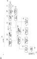
本発明の実施形態について説明する。図2は、第1の実施形態に係る撮像装置100の構成を示すブロック図である。以下、図2の撮像装置100の各構成部とその一例の動作について具体的に説明する。
[First Embodiment]
An embodiment of the present invention will be described. FIG. 2 is a block diagram illustrating a configuration of the
撮像装置100は、撮像光学系の光軸と垂直に移動可能な補正レンズ131と補正レンズ132との2つの補正レンズ(像ブレ補正レンズ)を有し、補正レンズ131を光学式ブレ補正に用いる。また、撮像装置100は、補正レンズ131の制御モードとして、ブレ補正モード又は被写体追尾モードを選択可能である。ブレ補正モードの場合、撮像装置100は、補正レンズ132を光学式ブレ補正制御に用いる。被写体追尾モードの場合、撮像装置100は、補正レンズ132を被写体追尾制御に用いる。
The
まずは、補正レンズ131を用いた光学式ブレ補正の説明を行う。角速度センサ101は、撮像装置100に加わる振れを角速度信号として検出し、その角速度信号をA/D変換器102に供給する。A/D変換器102は、角速度センサ101から供給される角速度信号をデジタル化してμCOM(マイクロコンピュータ)103内部の信号分割部104に供給する。以下では、デジタル化した角速度信号を角速度データと表現する。
First, optical blur correction using the
信号分割部104は、駆動制御切替部115から通知される現在の補正レンズ132の制御モードを示す情報を受け取り、制御モードに応じて出力を切り替える。被写体追尾モードの場合、角速度データに基づく光学式ブレ補正は補正レンズ131のみで行われるため、信号分割部104は、角速度データを分割せずにレンズ駆動量演算部105へ出力する。他方、ブレ補正モードの場合、補正レンズ131と補正レンズ132との2つを使用して光学式ブレ補正が行われるため、信号分割部104は、角速度データを分割してレンズ駆動量演算部105及び駆動制御切替部115に出力する。信号分割部104の詳細は後述する。ブレ補正モード又は被写体追尾モードのいずれの場合であっても、レンズ駆動量演算部105は、信号分割部104が出力する角速度データに基づいて補正レンズ131を駆動するための駆動量を算出し、減算器106に出力する。
The
減算器106は、レンズ駆動量演算部105の出力から後述のレンズ位置データを減算して得られる偏差データを制御フィルタ107に出力する。制御フィルタ107は、入力データを所定のゲインで増幅する増幅器、及び位相補償フィルタを含む。減算器106から供給された偏差データは、制御フィルタ107において増幅器及び位相補償フィルタによる信号処理が行われた後、パルス幅変調部108に出力される。
The
パルス幅変調部108は、制御フィルタ107を通過して供給されたデータを、パルス波のデューティー比を変化させる波形(即ち、PWM波形)に変調して、モータ駆動部109に供給する。モータ110は、補正レンズ131の駆動用のボイス・コイル型モータである。モータ110がモータ駆動部109により駆動されることにより、補正レンズ131が光軸と垂直な方向に移動される。ここで、端子A111と端子A126は、各々が電気的に接続されていることを示している。また、端子B112と端子B127は、各々が電気的に接続されていることを示している。
The pulse
位置検出センサ113は、磁石とそれに対向する位置に備えられたホール・センサとを含み、補正レンズ131の光軸と垂直な方向への移動量を検出し、その検出結果をA/D変換器114に出力する。A/D変換器114は、位置検出センサ113の検出信号をデジタルデータであるレンズ位置データに変換し、上述した減算器106に供給する。これによって、レンズ駆動量演算部105の出力に対して、補正レンズ131の光軸と垂直な方向への移動量を追従させる、フィードバック制御系を構成している。
The
補正レンズ131は、例えばシフトレンズであり、光軸に対し垂直平面上を移動されることにより光軸を偏向する、振れ補正可能な光学系である。補正レンズ131の移動が行われた結果、撮像装置100の振れによって生じる撮像面上の被写体の縦横方向のブレが補正された像が、撮像素子133に結像される。
The
ここで、もう1つの補正レンズ制御系、即ち、レンズ駆動量演算部116からA/D変換器125の処理内容は、基本的には、レンズ駆動量演算部105からA/D変換器114の処理と同じであるため、詳細な説明は省略する。但し、ブレ補正モードの場合と被写体追尾モードの場合とで、駆動制御切替部115からレンズ駆動量演算部116に入力されるデータが異なるため、結果として、補正レンズ132の制御も異なる。制御モードの切り替えに関係する処理については、後に詳細な説明を行う。
Here, the processing contents of the other correction lens control system, that is, the lens driving
以下では、撮像した画像を保存及び表示する処理について説明する。また、撮像した画像から顔位置を検出する処理と、動きベクトルを検出する処理に関しても説明する。 Below, the process which preserve | saves and displays the imaged image is demonstrated. A process for detecting a face position from a captured image and a process for detecting a motion vector will also be described.
撮像素子133は、補正レンズ131と補正レンズ132を含む撮像光学系130によって結像された被写体像を撮像画像信号としての電気信号に変換し、信号処理部134に供給する。信号処理部134は、撮像素子133により得られた信号から、例えばNTSCフォーマットに準拠したビデオ信号(映像信号)を生成して画像メモリ140に供給する。また、信号処理部134は、顔検出部135と動きベクトル検出部137にもそれぞれビデオ信号を供給する。但し、顔検出部135と動きベクトル検出部137に供給するビデオ信号は、画像メモリ140に供給するビデオ信号と同じものでなくてもよい。
The
顔検出部135は、ビデオ信号に対して任意の公知の顔認識処理を施して撮影画面内の人物の顔(所定の被写体)の領域を検出する、被写体検出処理を行う。そして、顔検出部135は、検出結果を被写体移動量演算部136に供給する。被写体移動量演算部136は、顔検出部135で検出した人物の顔領域位置に基づき、前回の撮像画像から今回の撮像画像までの間における人物の移動量を算出する、移動量取得処理を行う。そして、被写体移動量演算部136は、算出結果を被写体移動量データとして駆動制御切替部115に供給する。
The
動きベクトル検出部137は、信号処理部134から出力されるビデオ信号を、1フィールド(又は1フレーム)期間遅延させるため不図示のメモリに保持しておく。そして、動きベクトル検出部137は、今回の撮像により取得したビデオ信号の画像(第1の撮像画像)と前回の撮像により取得した1フィールド(又は1フレーム)前の画像(第2の撮像画像)との2枚の画像の輝度信号に基づき、動きベクトルを検出する。
The motion
具体的な動きベクトルの検出方法は、例えば、従来提案されているブロックマッチング法などを用いる。ブロックマッチング法は、撮像画像をブロックと呼ばれる領域に分割し、例えば1フレーム前の撮像画像と現在の撮像画像との類似箇所をブロック単位で検出する方法である。1フレーム前の撮像画像内の任意の範囲において、現在の撮像画像内の任意ブロックとの相関値が最も大きい場所が類似ブロック位置として検出される。現在の撮像画像内の任意ブロック位置と1フレーム前の撮像画像内の類似ブロック位置との変位量を求めることにより、撮像画像のフレーム間の動き情報、即ち動きベクトルが検出される。 As a specific motion vector detection method, for example, a conventionally proposed block matching method or the like is used. The block matching method is a method in which a captured image is divided into areas called blocks and, for example, a similar portion between the captured image one frame before and the current captured image is detected in units of blocks. A place having the largest correlation value with an arbitrary block in the current captured image in an arbitrary range in the captured image one frame before is detected as a similar block position. By obtaining a displacement amount between an arbitrary block position in the current captured image and a similar block position in the captured image one frame before, motion information between frames of the captured image, that is, a motion vector is detected.
なお、ブロックマッチング法は、動きベクトル検出部137における動きベクトル検出方法の一例であり、動きベクトル検出方法はブロックマッチング法以外の方法を用いてもよい。また、マッチング演算については、尾上守夫等により、情報処理Vol.17,No.7,p.634 〜640 July 1976で詳しく論じられている。
The block matching method is an example of a motion vector detection method in the motion
代表ベクトル決定部138は、動きベクトル検出部137において検出される複数の動きベクトルから画像全体の動きを示す代表ベクトルを算出し、算出した代表ベクトルをメモリ読み出し制御部139に供給する。なお、代表ベクトルの算出方法としては、複数のブロック単位の動きベクトルの中央値又は平均値を代表ベクトルとする方法が挙げられる。ここ以降で動きベクトルと表記しているものは、代表ベクトルを示す場合もある。
The representative
メモリ読み出し制御部139は、代表ベクトル決定部138で検出した動きベクトルに応じて、画像の動きが相殺されるように画像メモリ140の読み出し位置を制御する。これにより、画像メモリ140からブレが補正されたビデオ信号(出力画像)が出力される。このように画像メモリ140の読み出し位置を変更して出力画像取得処理を行うことでブレ補正を行う方法は、電子式ブレ補正と呼ばれる。本実施形態では、撮像装置100は、ブレ補正モードの場合は電子式ブレ補正を行うが、被写体追尾モードの場合は電子式ブレ補正を行わない。そのため、メモリ読み出し制御部139は、駆動制御切替部115で決定される補正レンズ132の制御モードに応じて、処理を変更する。但し、この処理の詳細は後述するものとする。
The memory read
画像メモリ140から出力されるビデオ信号は、記録制御部141及び表示制御部143に供給される。記録制御部141は、記録開始や終了の指示に用いる操作部(不図示)によって映像信号の記録が指示された場合、画像メモリ140から供給されたビデオ信号を記録媒体142に出力し、記録させる。記録媒体142は、半導体メモリ等の情報記録媒体やハードディスク等の磁気記録媒体である。表示制御部143は、画像メモリ140から供給されたビデオ信号を出力して表示デバイス144に画像を表示させる。表示制御部143は表示デバイス144を駆動し、表示デバイス144は液晶表示素子(LCD)等により画像を表示する。
The video signal output from the
以下、図3を参照して、補正レンズ132の制御モードの切り替えに伴って撮像装置100が実行する処理について説明する。ここで、フローチャートの説明に先立ち、いずれの制御モードに切り替えるかを選択する方法の具体例について説明する。1つの例として、撮像装置100は、ブレ補正モードと被写体追尾モードとを選択可能なメニューを備えている。撮影者がメニューからブレ補正モードを選択した場合、駆動制御切替部115は制御モードをブレ補正に切り替える。撮影者が被写体追尾モードを選択した場合、駆動制御切替部115制御モードを被写体追尾に切り替える。別の例として、撮影者がタッチパネルなどの操作で追尾させたい被写体を選択すると、駆動制御切替部115は、制御モードをブレ補正モードから被写体追尾モードに切り替える。更に別の例として、顔検出部135が人物など追尾対象の被写体を検出した場合に、駆動制御切替部115は、制御モードを被写体追尾モードに切り替え、顔検出部135が追尾対象の被写体が検出できなかった場合は、制御モードをブレ補正モードに切り替える。
Hereinafter, with reference to FIG. 3, a process executed by the
駆動制御切替部115が補正レンズ132の制御モードをブレ補正モードと被写体追尾モードとの間で切り替えると、本フローチャートの処理が開始する。S100で、駆動制御切替部115は、補正レンズ132の現在の制御モードを信号分割部104とメモリ読み出し制御部139に通知する。
When the drive
S101において、現在の制御モードがブレ補正モードであるか被写体追尾モードであるかに応じて、処理が分岐する。ブレ補正モードの場合、処理はS102に進み、被写体追尾モードの場合、処理はS105に進む。 In S101, the process branches depending on whether the current control mode is the blur correction mode or the subject tracking mode. In the case of the blur correction mode, the process proceeds to S102, and in the subject tracking mode, the process proceeds to S105.
S102で、信号分割部104は、S100において駆動制御切替部115から通知された制御モードに従った動作を開始する。具体的には、信号分割部104は、角速度データを分割してレンズ駆動量演算部105と駆動制御切替部115へそれぞれ出力する。角速度データの分割方法の一例として、レンズ駆動量演算部105への出力は角速度データに所定の係数n(n<1)を乗じた値であり、駆動制御切替部115への出力は角速度データに係数(1−n)を乗じた値である。また、角速度データの分割方法の別の例として、信号分割部104は、低周波通過フィルタ又は高周波通過フィルタの機能を有し、角速度データを周波数分離して、一方の出力を低周波信号、他方の出力を高周波信号とする。
In S102, the
S103で、駆動制御切替部115は、制御モードに従った動作を開始する。具体的には、駆動制御切替部115は、信号分割部104から供給される分割された角速度データをレンズ駆動量演算部116に出力する。このとき、駆動制御切替部115は、被写体移動量演算部136から供給される被写体移動量データを無効化する。これにより、補正レンズ132は、分割された角速度データのみに基づいて駆動され、補正レンズ132による光学式ブレ補正が行われる。このように、分割された角速度データの一方の出力に基づいて補正レンズ131を駆動し、他方の出力に基づいて補正レンズ132を駆動することで、2つの補正レンズを使用した光学式ブレ補正が実現される。
In S103, the drive
S104で、メモリ読み出し制御部139は、S100において駆動制御切替部115から通知された制御モードに従った動作を開始する。具体的には、メモリ読み出し制御部139は、代表ベクトル決定部138から供給される動きベクトル(代表ベクトル)に基づいて、画像メモリ140からの画像読み出し位置を制御する。これにより、光学式ブレ補正での補正誤差による画像ブレを電子式ブレ補正で更に補正することが可能となる。
In S104, the memory read
他方、被写体追尾モードの場合、S105で、信号分割部104は、S100において駆動制御切替部115から通知された制御モードに従った動作を開始する。具体的には、信号分割部104は、A/D変換器102から供給される角速度データを分割せずにレンズ駆動量演算部105へ出力する。このとき、信号分割部104は、駆動制御切替部115に対しては、0や無効な値などを出力し、駆動制御切替部115が信号分割部104の出力を使用しないようにする。
On the other hand, in the subject tracking mode, in S105, the
S106で、駆動制御切替部115は、制御モードに従った動作を開始する。具体的には、駆動制御切替部115は、信号分割部104から供給されるデータを無効化し、被写体移動量演算部136から出力される被写体移動量データをレンズ駆動量演算部116に出力する。これにより、補正レンズ132が被写体の移動に合わせて駆動して光軸を偏向するため、被写体が移動する場合であっても被写体位置が画像内の略一定位置に収まるようになる。
In S106, the drive
S107で、メモリ読み出し制御部139は、S100において駆動制御切替部115から通知された制御モードに従った動作を開始する。具体的には、メモリ読み出し制御部139は、電子式ブレ補正が行われないようにする。即ち、メモリ読み出し制御部139は、画像メモリ140からの画像読み出し位置が変更されないように、予め決められた固定位置を画像読み出し位置とする。このS107の処理により電子式ブレ補正を止めることで、補正レンズ132の被写体追尾によって生じる背景位置変化を電子式ブレ補正で抑制しようとする誤補正を防ぐことが可能となる。
In S107, the memory read
以上説明したように、第1の実施形態によれば、撮像装置100は、補正レンズ132の制御モードとしてブレ補正モードと被写体追尾モードとの間で切り替え可能である。そして、撮像装置100は、ブレ補正モードの場合は電子式ブレ補正を行うが、被写体追尾モードの場合は電子式ブレ補正を行わない。
As described above, according to the first embodiment, the
これにより、電子式ブレ補正機能を有する撮像装置が補正レンズ132のような光学系により被写体追尾を行う際に、電子式ブレ補正機能が被写体追尾を妨げることを抑制することが可能となる。
Accordingly, when an imaging apparatus having an electronic blur correction function performs subject tracking using an optical system such as the
なお、上記の説明においては、撮像装置100の振れを検出するために角速度センサ101の出力を用いたが、これは種々の変形が可能である。例えば、加速度センサを用いてもよい。また、光学式ブレ補正及び被写体追尾を行うために、補正レンズ132を駆動するものとしたが、これに限定されるものではない。例えば、撮像装置100は、補正レンズ132の代わりに撮像素子133を駆動することにより、光学式ブレ補正及び被写体追尾を行ってもよい。或いは、光学式ブレ補正及び被写体追尾を行うためにプリズムを用いる方法等も利用可能である。撮像光学系130の光軸と撮像素子133との位置関係を変化させる方法であれば、いかなる方法によって光学式ブレ補正及び被写体追尾を行ってもよい。
In the above description, the output of the
また、図3のS107における、メモリ読み出し制御部139の制御は、必ずしも固定値に基づいて画像読み出しを行うようにする制御に限定されない。例えば、メモリ読み出し制御部139は、読み出し位置の変更可能範囲を、被写体追尾時モードの場合はブレ補正モードの場合よりも小さい範囲にした上で、電子式ブレ補正を行ってもよい。換言すると、メモリ読み出し制御部139は、被写体追尾時モードの場合には、動きベクトルに1未満の所定のゲインをかけてブレ補正モードの場合よりもブレ補正効果を小さくすればよく、ブレ補正効果を完全に0にする必要は無い。この場合でも、被写体追尾時の背景移動に基づく動きベクトルが電子式ブレ補正に与える影響が小さくなるため、電子式ブレ補正機能が被写体追尾を妨げることがある程度は抑制される。ここで述べた種々の変形に関しては、以降の実施形態でも当てはまるものである。
In addition, the control of the memory
[第2の実施形態]
図4は、第2の実施形態に係る撮像装置200の構成を示すブロック図である。図4において、図2と同様の構成には同一の符号を付し、説明は省略する。第1の実施形態では、撮像装置100は、被写体追尾モードの場合、電子式ブレ補正の効果を小さくする、または0にしていた。これに対し、第2の実施形態では、撮像装置200は、被写体追尾モードの場合であっても、代表ベクトルを利用した補正処理を行う。但し、詳細は後述するが、この補正処理は、画像メモリ140のメモリ読み出し位置を変更するという点では第1の実施形態の電子式ブレ補正と同様であるが、ブレを補正するのではなく、被写体追尾の精度を向上させる役割を果たす。このような補正処理を、「電子式追尾補正」と呼ぶ。
[Second Embodiment]
FIG. 4 is a block diagram illustrating a configuration of the
図4に示す撮像装置200においては、μCOM201が顔サイズ判定部203を備えており、顔検出部202は、検出した顔領域情報から顔サイズに関する情報を顔サイズ判定部203に通知する。また、メモリ読み出し制御部204は、レンズ駆動量演算部116で算出した補正レンズ132の駆動量を受け取る構成になっている。メモリ読み出し制御部204は、顔サイズ判定部203から通知される判定結果に基づいて処理内容を変更する。
In the
撮像装置200は、補正レンズ132の制御モードがブレ補正モードの場合は第1の実施形態と同様に電子式ブレ補正を行い、補正レンズ132の制御モードが被写体追尾モードの場合は電子式追尾補正を行う。
The
図5は、撮像装置200が実行する電子式追尾補正の処理を示すフローチャートである。本フローチャートは、図3のS107を置き換えるものである。まず、S200で、顔検出部202は、顔サイズ情報、即ち撮像画像内に占める主被写体の顔の大きさを顔サイズ判定部203に通知する。
FIG. 5 is a flowchart illustrating the electronic tracking correction process performed by the
S201で、顔サイズ判定部203は、顔検出部202から通知された顔サイズ情報に基づいて、顔サイズが閾値以上であるか否かを判定する。閾値以上の場合、処理はS202に進み、閾値未満の場合、処理はS203に進む。ここで、閾値は、代表ベクトル決定部138で決定される代表ベクトルに対して、追尾対象の主被写体の移動と背景の位置変化のいずれがより強く寄与するかの境界となる値である。即ち、動きベクトル検出部137で検出された複数の動きベクトルのうち、被写体の動きを表す動きベクトルの数が背景の位置変化を表す動きベクトルの数よりも多くなるような被写体の顔サイズが、閾値となる。従って、主被写体の顔サイズが閾値以上の場合は、代表ベクトルは主に主被写体の移動に基づいて算出され、顔サイズが閾値未満の場合は、代表ベクトルは主に背景の位置変化に基づいて算出されることとなる。
In step S <b> 201, the face
S202で、メモリ読み出し制御部204は、代表ベクトルに基づいて画像メモリ140の読み出し位置を制御する。代表ベクトルは主に主被写体移動に基づいて算出されているので、この制御により、被写体位置のズレ(即ち、補正レンズ132による被写体追尾の誤差)を補正する電子式追尾補正が実現される。
In S202, the memory
他方、S203では、メモリ読み出し制御部204は、レンズ駆動量演算部116で算出される補正レンズ132のレンズ駆動量と代表ベクトルとの差分に基づいて電子式追尾補正を行う。
On the other hand, in S <b> 203, the memory
S203でのメモリ読み出し制御部204の処理について、図6を参照して詳細に説明する。図6(a)は、レンズ駆動量演算部116で算出される補正レンズ132のレンズ駆動量を表す。このレンズ駆動量は、主被写体位置に基づいて算出されたものであり、補正レンズ132の駆動の目標量に対応する。補正レンズ132を図6(a)に基づいて追尾駆動することで、これまで述べてきたように背景にある固定被写体位置が変化し、前述の背景位置変化が図6(b)に示すような代表ベクトルとして検出される。ここで、図6(a)のレンズ駆動量と図6(b)の代表ベクトルとの波形の違いは、補正レンズ132の駆動がレンズ駆動量に対し完全に追従できていないことによる、追従誤差量を表す。即ち、代表ベクトルから、補正レンズ132の駆動の目標量に対応するレンズ駆動量を差し引いた値が、レンズ駆動誤差として図6(c)に示すような波形で表れる。なお、図4には不図示であるが、代表ベクトルからレンズ駆動量を差し引く処理のため、メモリ読み出し制御部204は、レンズ駆動量の単位を代表ベクトルと合わせる処理を行う。
The processing of the memory read
メモリ読み出し制御部204は、図6(c)に示すレンズ駆動誤差に基づいて画像メモリ140の読み出し位置を変更する。これにより、補正レンズ132による被写体追尾を妨げるような電子式ブレ補正は回避しつつ、補正レンズ132の駆動誤差(即ち、被写体追尾の誤差)を補正することが可能となる。
The memory read
以上説明したように、第2の実施形態によれば、撮像装置200は、ブレ補正モードの場合は電子式ブレ補正を行い、被写体追尾モードの場合は電子式追尾補正を行う。これにより、電子式ブレ補正機能が被写体追尾を妨げることを抑制し、更に、被写体追尾の誤差を補正することが可能となる。
As described above, according to the second embodiment, the
[第3の実施形態]
図7は、第3の実施形態に係る撮像装置300の構成を示すブロック図である。図7において、図2と同様の構成には同一の符号を付し、説明は省略する。撮像装置300は、第2の実施形態における撮像装置200とは異なる方法によって、電子式追尾補正を実現する。
[Third Embodiment]
FIG. 7 is a block diagram illustrating a configuration of an
図7に示す撮像装置300においては、μCOM301が動きベクトル検出範囲算出部302を備えている。図8は、撮像装置300が実行する電子式追尾補正の処理を示すフローチャートである。本フローチャートは、図3のS107を置き換えるものである。
In the
S300で、顔検出部135は、顔領域検出を行い、検出した顔領域情報を動きベクトル検出範囲算出部302に通知する。S301で、動きベクトル検出範囲算出部302は、S300において通知された顔領域情報に基づいて動きベクトル検出範囲を算出し、算出した動きベクトル検出範囲を動きベクトル検出部303に通知する。
In step S300, the
動きベクトル検出範囲算出部302で算出される動きベクトル検出範囲の一例は図9に示す通りである。補正レンズ132の制御モードがブレ補正モードの場合、図9(a)に示すように、検出範囲は撮像画像の略全域であるが、補正レンズ132の制御モードが被写体追尾モードの場合は、図9(b)に示すように、検出範囲は顔領域周辺のみである。図9(b)において、「顔領域」と記載された点線枠が顔検出部135で検出された顔領域を示しており、このときの動きベクトル検出範囲は、該顔領域が含まれる6つのブロックのみである。但し、顔領域の配置によっては検出範囲に含まれるブロック数が極めて少数になってしまうため、検出精度が低下する要因となる。そこで、動きベクトル検出数が少なくなり過ぎることを回避するために、顔領域が含まれるブロック及び該ブロックと隣接するブロックまでを検出範囲としてもよい。換言すると、被写体追尾モード時に設定される動きベクトル検出範囲は、主被写体を含みつつ、ブレ補正モード時に設定される動きベクトル検出範囲よりも狭ければ、どのような範囲であっても構わない。
An example of the motion vector detection range calculated by the motion vector detection
また、動きベクトル検出範囲の算出方法別の例として、動きベクトル検出範囲算出部302は、動きベクトルの信頼性を判定し、信頼性に基づいてブロック数やブロックサイズを決定し、動きベクトル検出範囲としてもよい。
As another example of the method for calculating the motion vector detection range, the motion vector detection
S302で、動きベクトル検出部303は、動きベクトル検出範囲算出部302から通知された動きベクトル検出範囲内で、動きベクトルの検出を行う。S303で、代表ベクトル決定部138は、動きベクトル検出部303で検出された動きベクトルに基づいて代表ベクトルを決定する。代表ベクトルの決定方法は、ブレ補正モードの場合と同様である。S304で、メモリ読み出し制御部139は、代表ベクトルに基づいて電子式追尾補正を行う。ここでの処理は、図2のS202と同様である。
In S <b> 302, the motion
以上説明したように、第3の実施形態によれば、撮像装置300は、被写体追尾モードの場合、顔領域に基づいて算出された動きベクトル検出範囲に基づいて動きベクトルを検出し、電子式追尾補正を行う。これにより、電子式ブレ補正機能が被写体追尾を妨げることを抑制し、更に、被写体追尾の誤差を補正することが可能となる。
As described above, according to the third embodiment, in the subject tracking mode, the
[第4の実施形態]
図10は、第4の実施形態に係る撮像装置400の構成を示すブロック図である。図10において、図2と同様の構成には同一の符号を付し、説明は省略する。
[Fourth Embodiment]
FIG. 10 is a block diagram illustrating a configuration of an
撮像装置400は、補正レンズ132の制御モードとして、ブレ補正モード及び被写体追尾モードに加えて、構図変更モードを選択可能である。構図変更モードにおいて、撮像装置400は、補正レンズ132を移動させることで、映像にパンニング、又はチルティング効果を持たせる構図変更制御を実行可能である。
The
補正レンズ132を構図変更のために駆動させる場合は、電子式ブレ補正を行うと構図変更を妨げてしまう。そのため、撮像装置400は、構図変更モードの場合、第1の実施形態における被写体追尾モードの場合と同様に、画像メモリ140のメモリ読み出し位置変更を行わず、更に、補正レンズ131の駆動も停止させる。
In the case where the
図10に示す撮像装置400は、レンズ駆動パラメータ設定部402を備え、μCOM401内の駆動制御切替部403は、レンズ駆動パラメータ設定部402の出力を受ける。また、駆動制御切替部403は、レンズ駆動量演算部404に対し、レンズ駆動量を0に設定するように制御することができる。
An
以下、図11を参照して、補正レンズ132の制御モードの切り替えに伴って撮像装置400が実行する処理について説明する。駆動制御切替部403が補正レンズ132の制御モードをブレ補正モード、被写体追尾モード、及び構図変更モードの間で切り替えると、本フローチャートの処理が開始する。
Hereinafter, with reference to FIG. 11, a process executed by the
S400で、駆動制御切替部403は、補正レンズ132の現在の制御モードを信号分割部104、メモリ読み出し制御部139、及びレンズ駆動量演算部404に通知する。
In step S400, the drive
S401において、現在の制御モードに応じて処理が分岐する。構図変更モードの場合、処理はS402に進み、ブレ補正モード又は被写体追尾モードの場合、処理はS408に進む。S408の処理は、第1の実施形態から第3の実施形態で説明したものと同様である。 In S401, the process branches according to the current control mode. In the composition change mode, the process proceeds to S402, and in the shake correction mode or the subject tracking mode, the process proceeds to S408. The process of S408 is the same as that described in the first to third embodiments.
S402で、信号分割部104は、S400において駆動制御切替部403から通知された制御モードに従った動作を開始する。具体的には、信号分割部104は、A/D変換器102から供給される角速度データを分割せずにレンズ駆動量演算部404へ出力する。このとき、信号分割部104は、駆動制御切替部403に対しては、0や無効な値などを出力し、駆動制御切替部115が信号分割部104の出力を使用しないようにする。
In S402, the
S403で、レンズ駆動パラメータ設定部402は、撮影者が設定したレンズ駆動パラメータを駆動制御切替部403に出力する。ここで、レンズ駆動パラメータの一例として、補正レンズ132の移動開始位置、移動終了位置、及び、移動開始位置から移動終了位置まで移動する速度の組み合わせが挙げられる。別の一例として、補正レンズ132の移動開始位置、移動速度、移動方向、及び移動完了までに要する時間の組み合わせが挙げられる。但し、撮影者が所望する構図変更を満たすためのパラメータは、これらに限定されるものではない。
In step S <b> 403, the lens drive
S404で、駆動制御切替部403は、制御モードに従った動作を開始する。具体的には、駆動制御切替部403は、信号分割部104から供給されるデータを無効化し、レンズ駆動パラメータ設定部402から出力されるレンズ駆動パラメータをレンズ駆動量演算部116に出力する。
In S404, the drive
S405で、レンズ駆動量演算部116は、駆動制御切替部403から出力されるレンズ駆動パラメータに基づいて補正レンズ132のレンズ駆動量を算出し、減算器117へ出力する。このレンズ駆動量に基づいて補正レンズ132を駆動し光軸を偏向することで、撮像装置400が固定状態で撮影が行われても、あたかも撮像装置400をパンニング又はチルティングしたような映像を撮影することが可能となる。
In step S <b> 405, the lens drive
S406で、レンズ駆動量演算部404は、S400において駆動制御切替部403から通知された制御モードに従った動作を開始する。具体的には、レンズ駆動量演算部404は、補正レンズ132による構図変更を妨げないようにするために、信号分割部104から供給される角速度データを無効化し、レンズ駆動量を任意の固定値で減算器106に出力する。但し、S406の処理は、補正レンズ131の駆動を停止させる処理ならば、これに限定されるものではない。例えば、信号分割部104が駆動制御切替部403からの通知を受けて、駆動制御切替部403とレンズ駆動量演算部404とのいずれにも0、任意の固定値、又は無効データなどを出力してもよい。或いは、制御フィルタ107やパルス幅変調部108でレンズ駆動停止処理を行ってもよい。また、補正レンズ131の構造でレンズ固定用部材を備え、構図変更モードの場合は補正レンズ131をレンズ固定用部材で固定させてもよいものとする。
In S406, the lens driving
S407で、メモリ読み出し制御部139は、S400において駆動制御切替部403から通知された制御モードに従った動作を開始する。具体的には、メモリ読み出し制御部139は、電子式ブレ補正が(電子式追尾補正も)行われないようにする。即ち、メモリ読み出し制御部139は、画像メモリ140からの画像読み出し位置が変更されないように、予め決められた固定位置を画像読み出し位置とする。このS407の処理で電子式ブレ補正や電子式追尾補正を止めることで、補正レンズ132による構図変更が妨げられないようにすることが可能となる。なお、図3のS107と同様、メモリ読み出し制御部139は、画像読み出し位置を固定する代わりに、読み出し位置の変更可能範囲がブレ補正モード時よりも小さくなるように代表ベクトルに1未満の所定のゲインをかけて補正効果を小さくした上で、電子式ブレ補正を行ってもよい。
In S407, the memory read
以上説明したように、第4の実施形態によれば、撮像装置400は、補正レンズ132の制御モードとして、ブレ補正モード及び被写体追尾モードに加えて、構図変更モードを選択可能である。そして、撮像装置100は、構図変更モードの場合は電子式ブレ補正を行わない。
As described above, according to the fourth embodiment, the
これにより、電子式ブレ補正機能を有する撮像装置が補正レンズ132のような光学系により構図変更を行う際に、電子式ブレ補正機能が構図変更を妨げることを抑制することが可能となる。
This makes it possible to prevent the electronic shake correction function from interfering with the composition change when the imaging apparatus having the electronic shake correction function changes the composition using the optical system such as the
なお、撮像装置400は、補正レンズ131を停止し、補正レンズ132で構図変更を行う代わりに、補正レンズ132を停止し、補正レンズ131で構図変更を行ってもよい。
Instead of stopping the
[第5の実施形態]
図12は、第5の実施形態に係る撮像装置500の構成を示すブロック図である。
[Fifth Embodiment]
FIG. 12 is a block diagram illustrating a configuration of an
第5の実施形態においては、上述してきた第1から第4の実施形態における撮像装置に対し、代表ベクトルを補正レンズ132の駆動にも使用する構成を追加した。図12では、第5の実施形態の特徴となる部分のみ図示し、前述までの実施形態で説明してきた構成と差異がないブロックは図示を省略、または同一の符号を付し、説明も省略する。
In the fifth embodiment, a configuration in which the representative vector is also used to drive the
撮像装置500におけるμCOM501は、レンズ駆動量換算部504と、加算器505を備え、駆動制御切替部502は、メモリ読み出し制御部139に加えてレンズ駆動量換算部504にも制御モードを通知する。
The
代表ベクトル決定部503は、動きベクトル検出部137で検出される動きベクトルの中から代表ベクトルを決定し、レンズ駆動量換算部504とメモリ読み出し制御部139に代表ベクトルを出力する。
The representative
レンズ駆動量換算部504は、代表ベクトルを補正レンズ132(図2参照)を駆動するための補正量に換算する。ただし、レンズ駆動量換算部504による換算処理は、単純な単位変換処理だけでなく、積分や位相合わせなどのフィルタ演算処理も含むものとする。
The lens drive
レンズ駆動量換算部504の出力を、以下ではベクトルレンズ駆動量と定義する。加算器505をレンズ駆動量演算部116の後段に加えることで、位置検出センサ124からのフィードバック系とは異なるベクトルによるフィードバック制御を実現する。
Hereinafter, the output of the lens driving
ここで、レンズ駆動量換算部504は、駆動制御切替部502から通知された制御モードがブレ補正モードでない場合には、ベクトルによる補正レンズ132の駆動が行われない(或いは、小さくなる)ようにする。即ち、レンズ駆動量換算部504は、ベクトルレンズ駆動量に1未満の所定のゲインをかけて、加算器505への出力を0またはブレ補正モード時の出力よりも小さい値とすることで、補正効果を小さくする。この処理により、被写体追尾モード時に補正レンズ132の被写体追尾によって生じる背景位置変化により生じるベクトルによる、ブレの誤補正を抑制することが可能となる。
Here, when the control mode notified from the drive
第1から第4の実施形態では、主に電子式ブレ補正機能が被写体追尾又は構図変更を妨げることを抑制することを説明してきた。しかしながら、第5の実施形態から明らかな通り、ブレ補正機能は電子式に限定されず、電子式であれ光学式であれ、像ブレ補正機能が被写体追尾又は構図変更を妨げることを抑制することが可能である。 In the first to fourth embodiments, it has been mainly explained that the electronic blur correction function suppresses the object tracking or composition change from being hindered. However, as is apparent from the fifth embodiment, the blur correction function is not limited to the electronic system, and it is possible to suppress the image blur correction function from interfering with subject tracking or composition change, whether electronic or optical. Is possible.
[その他の実施形態]
上記の各実施形態では、補正レンズ131と補正レンズ132の2つの補正レンズを備える撮像装置について説明した。しかしながら、各撮像装置は、補正レンズ131を備えなくても構わない。即ち、各撮像装置は、1つの補正レンズの制御モードを、ブレ補正モード及び被写体追尾モード(第4の実施形態の場合、更に構図変更モード)の間で切り替えても構わない。
[Other Embodiments]
In each of the above-described embodiments, the imaging apparatus including the two correction lenses of the
また、本発明は、以下の処理を実行することによっても実現される。即ち、上述した実施形態の機能を実現するソフトウェア(プログラム)を、ネットワーク又は各種記憶媒体を介してシステム或いは装置に供給し、そのシステム或いは装置のコンピュータ(又はCPUやMPU等)がプログラムを読み出して実行する処理である。 The present invention can also be realized by executing the following processing. That is, software (program) that realizes the functions of the above-described embodiments is supplied to a system or apparatus via a network or various storage media, and a computer (or CPU, MPU, etc.) of the system or apparatus reads the program. It is a process to be executed.
100…撮像装置、103…μCOM、105…レンズ駆動量演算部、115…駆動制御切替部、116…レンズ駆動量演算部、131…補正レンズ、132…補正レンズ、135…顔検出部、136…被写体移動量演算部、137…動きベクトル検出部、138…代表ベクトル決定部
DESCRIPTION OF
Claims (8)
前記撮像素子で撮像された2枚の撮像画像より撮像画面内を移動する前記所定の被写体の移動量を取得する移動量取得手段と、
前記撮像素子に光束を導く撮像光学系を構成する光学素子を前記撮像光学系の光軸と異なる方向に移動させることで、前記撮像画面内における前記所定の被写体の移動量を抑制する被写体追尾手段と、
前記撮像素子で撮像された2枚の撮像画像を比較して像ブレ量を示す動きベクトルを検出する動きベクトル検出手段と、
前記動きベクトルに基づいて像ブレを補正する像ブレ補正手段と、
ユーザからのマニュアル指示に従って、前記被写体追尾手段による被写体追尾を行うか否かを切り替える切替手段と、
を備える撮像装置であって、
前記被写体追尾手段は、前記撮像装置が移動しておらず前記所定の被写体が移動している場合であっても、前記撮像画面内における前記所定の被写体の移動量を抑制し、
前記像ブレ補正手段は、前記被写体追尾を行う場合の像ブレ補正の効果を、前記被写体追尾を行わない場合の前記像ブレ補正の効果よりも小さくする
ことを特徴とする撮像装置。 Subject detection means for detecting a predetermined subject from a captured image captured by the image sensor;
A movement amount acquisition means for acquiring a movement amount of the predetermined subject that moves within the imaging screen from two captured images captured by the imaging element;
Subject tracking means for suppressing the amount of movement of the predetermined subject in the imaging screen by moving an optical element constituting an imaging optical system for guiding a light beam to the imaging element in a direction different from the optical axis of the imaging optical system. When,
A motion vector detection means for detecting a motion vector indicating an image blur amount by comparing two captured images captured by the image sensor;
Image blur correction means for correcting image blur based on the motion vector;
Switching means for switching whether to perform subject tracking by the subject tracking means according to a manual instruction from a user ;
The imaging device as Ru provided with,
The subject tracking means suppresses the amount of movement of the predetermined subject in the imaging screen even when the imaging device is not moving and the predetermined subject is moving,
The image pickup apparatus, wherein the image blur correction unit makes an effect of image blur correction when the subject tracking is performed smaller than an effect of the image blur correction when the subject tracking is not performed.
前記撮像素子で撮像された2枚の撮像画像より撮像画面内を移動する前記所定の被写体の移動量を取得する移動量取得手段と、
前記撮像素子に光束を導く撮像光学系を構成する光学素子を前記撮像光学系の光軸と異なる方向に移動させることで、前記撮像画面内における前記所定の被写体の移動量を抑制する被写体追尾手段と、
前記撮像素子で撮像された2枚の撮像画像を比較して像ブレ量を示す動きベクトルを検出する動きベクトル検出手段と、
前記動きベクトルに基づいて像ブレを補正する像ブレ補正手段と、
前記被写体追尾手段による被写体追尾を行うか否かを切り替える切替手段と、
前記所定の被写体のサイズが閾値以上であるか否かを判定する判定手段と、
を備え、
前記像ブレ補正手段は、前記被写体追尾を行う場合の像ブレ補正の効果を、前記被写体追尾を行わない場合の前記像ブレ補正の効果よりも小さくし、
前記像ブレ補正手段は、前記切替手段にて前記被写体追尾を行う制御が選択された場合でも、前記所定の被写体のサイズが前記閾値以上であるときは、前記像ブレ補正の効果を小さくしない
ことを特徴とする撮像装置。 Subject detection means for detecting a predetermined subject from a captured image captured by the image sensor;
A movement amount acquisition means for acquiring a movement amount of the predetermined subject that moves within the imaging screen from two captured images captured by the imaging element;
Subject tracking means for suppressing the amount of movement of the predetermined subject in the imaging screen by moving an optical element constituting an imaging optical system for guiding a light beam to the imaging element in a direction different from the optical axis of the imaging optical system. When,
A motion vector detection means for detecting a motion vector indicating an image blur amount by comparing two captured images captured by the image sensor;
Image blur correction means for correcting image blur based on the motion vector;
Switching means for switching whether to perform subject tracking by the subject tracking means;
Determination means for determining whether the size of the predetermined subject is equal to or larger than a threshold ;
With
The image blur correction means makes the effect of image blur correction when the subject tracking is smaller than the effect of image blur correction when the subject tracking is not performed,
The image blur correction unit does not reduce the effect of the image blur correction when the size of the predetermined subject is equal to or larger than the threshold even when the subject tracking control is selected by the switching unit.
It shall be the said imaging device.
前記撮像素子で撮像された2枚の撮像画像より撮像画面内を移動する前記所定の被写体の移動量を取得する移動量取得手段と、
前記撮像素子に光束を導く撮像光学系を構成する光学素子を前記撮像光学系の光軸と異なる方向に移動させることで、前記撮像画面内における前記所定の被写体の移動量を抑制する被写体追尾手段と、
前記撮像素子で撮像された2枚の撮像画像を比較して像ブレ量を示す動きベクトルを検出する動きベクトル検出手段と、
前記動きベクトルに基づいて像ブレを補正する像ブレ補正手段と、
前記被写体追尾手段による被写体追尾を行うか否かを切り替える切替手段と、
前記撮像素子で撮像された撮像画像において、前記動きベクトル検出手段により前記動きベクトルを検出する範囲を設定する設定手段と、
を備え、
前記像ブレ補正手段は、前記被写体追尾を行う場合の像ブレ補正の効果を、前記被写体追尾を行わない場合の前記像ブレ補正の効果よりも小さくし、
前記設定手段は、前記被写体追尾を行う場合の前記動きベクトルを検出する範囲を、前記被写体追尾を行わない場合の前記動きベクトルを検出する範囲よりも狭く設定する
ことを特徴とする撮像装置。 Subject detection means for detecting a predetermined subject from a captured image captured by the image sensor;
A movement amount acquisition means for acquiring a movement amount of the predetermined subject that moves within the imaging screen from two captured images captured by the imaging element;
Subject tracking means for suppressing the amount of movement of the predetermined subject in the imaging screen by moving an optical element constituting an imaging optical system for guiding a light beam to the imaging element in a direction different from the optical axis of the imaging optical system. When,
A motion vector detection means for detecting a motion vector indicating an image blur amount by comparing two captured images captured by the image sensor;
Image blur correction means for correcting image blur based on the motion vector;
Switching means for switching whether to perform subject tracking by the subject tracking means;
Setting means for setting a range in which the motion vector is detected by the motion vector detection means in a captured image captured by the image sensor ;
With
The image blur correction means makes the effect of image blur correction when the subject tracking is smaller than the effect of image blur correction when the subject tracking is not performed,
The setting means sets a range for detecting the motion vector when the subject tracking is performed to be narrower than a range for detecting the motion vector when the subject tracking is not performed.
It shall be the said imaging device.
撮像素子で撮像された撮像画像より所定の被写体を検出する被写体検出工程と、
前記撮像素子で撮像された2枚の撮像画像より撮像画面内を移動する前記所定の被写体の移動量を取得する移動量取得工程と、
前記撮像素子に光束を導く撮像光学系を構成する光学素子を前記撮像光学系の光軸と異なる方向に移動させることで、前記撮像画面内における前記所定の被写体の移動量を抑制する被写体追尾工程と、
前記撮像素子で撮像された2枚の撮像画像を比較して像ブレ量を示す動きベクトルを検出する動きベクトル検出工程と、
前記動きベクトルに基づいて像ブレを補正する像ブレ補正工程と、
ユーザからのマニュアル指示に従って、前記被写体追尾工程による被写体追尾を行うか否かを切り替える切替工程と、
を備え、
前記被写体追尾工程では、前記撮像装置が移動しておらず前記所定の被写体が移動している場合であっても、前記撮像画面内における前記所定の被写体の移動量を抑制し、
前記像ブレ補正工程では、前記被写体追尾を行う場合の像ブレ補正の効果を、前記被写体追尾を行わない場合の前記像ブレ補正の効果よりも小さくする
ことを特徴とする撮像方法。 An imaging method executed by an imaging device,
A subject detection step of detecting a predetermined subject from a captured image captured by the image sensor;
A movement amount acquisition step of acquiring a movement amount of the predetermined subject moving in the imaging screen from two captured images captured by the imaging element;
A subject tracking step of suppressing an amount of movement of the predetermined subject in the imaging screen by moving an optical element constituting an imaging optical system that guides a light beam to the imaging element in a direction different from the optical axis of the imaging optical system. When,
A motion vector detection step of detecting a motion vector indicating an image blur amount by comparing two captured images captured by the image sensor;
An image blur correction step of correcting image blur based on the motion vector;
A switching step of switching whether to perform subject tracking by the subject tracking step according to a manual instruction from the user ;
With
In the subject tracking step, even if the imaging device is not moving and the predetermined subject is moving, the movement amount of the predetermined subject in the imaging screen is suppressed,
In the image blur correction step, the image blur correction effect when the subject tracking is performed is made smaller than the image blur correction effect when the subject tracking is not performed.
撮像素子で撮像された撮像画像より所定の被写体を検出する被写体検出工程と、 A subject detection step of detecting a predetermined subject from a captured image captured by the image sensor;
前記撮像素子で撮像された2枚の撮像画像より撮像画面内を移動する前記所定の被写体の移動量を取得する移動量取得工程と、 A movement amount acquisition step of acquiring a movement amount of the predetermined subject moving in the imaging screen from two captured images captured by the imaging element;
前記撮像素子に光束を導く撮像光学系を構成する光学素子を前記撮像光学系の光軸と異なる方向に移動させることで、前記撮像画面内における前記所定の被写体の移動量を抑制する被写体追尾工程と、 A subject tracking step of suppressing an amount of movement of the predetermined subject in the imaging screen by moving an optical element constituting an imaging optical system that guides a light beam to the imaging element in a direction different from the optical axis of the imaging optical system. When,
前記撮像素子で撮像された2枚の撮像画像を比較して像ブレ量を示す動きベクトルを検出する動きベクトル検出工程と、 A motion vector detection step of detecting a motion vector indicating an image blur amount by comparing two captured images captured by the image sensor;
前記動きベクトルに基づいて像ブレを補正する像ブレ補正工程と、 An image blur correction step of correcting image blur based on the motion vector;
前記被写体追尾工程による被写体追尾を行うか否かを切り替える切替工程と、 A switching step of switching whether to perform subject tracking by the subject tracking step;
前記所定の被写体のサイズが閾値以上であるか否かを判定する判定工程と、 A determination step of determining whether the size of the predetermined subject is equal to or greater than a threshold;
を備え、 With
前記像ブレ補正工程では、前記被写体追尾を行う場合の像ブレ補正の効果を、前記被写体追尾を行わない場合の前記像ブレ補正の効果よりも小さくし、 In the image blur correction step, the effect of the image blur correction when the subject tracking is performed is smaller than the effect of the image blur correction when the subject tracking is not performed,
前記像ブレ補正工程では、前記切替工程にて前記被写体追尾を行う制御が選択された場合でも、前記所定の被写体のサイズが前記閾値以上であるときは、前記像ブレ補正の効果を小さくしない In the image blur correction process, even when the subject tracking control is selected in the switching process, the effect of the image blur correction is not reduced when the size of the predetermined subject is equal to or larger than the threshold value.
ことを特徴とする撮像方法。 An imaging method characterized by the above.
撮像素子で撮像された撮像画像より所定の被写体を検出する被写体検出工程と、 A subject detection step of detecting a predetermined subject from a captured image captured by the image sensor;
前記撮像素子で撮像された2枚の撮像画像より撮像画面内を移動する前記所定の被写体の移動量を取得する移動量取得工程と、 A movement amount acquisition step of acquiring a movement amount of the predetermined subject moving in the imaging screen from two captured images captured by the imaging element;
前記撮像素子に光束を導く撮像光学系を構成する光学素子を前記撮像光学系の光軸と異なる方向に移動させることで、前記撮像画面内における前記所定の被写体の移動量を抑制する被写体追尾工程と、 A subject tracking step of suppressing an amount of movement of the predetermined subject in the imaging screen by moving an optical element constituting an imaging optical system that guides a light beam to the imaging element in a direction different from the optical axis of the imaging optical system. When,
前記撮像素子で撮像された2枚の撮像画像を比較して像ブレ量を示す動きベクトルを検出する動きベクトル検出工程と、 A motion vector detection step of detecting a motion vector indicating an image blur amount by comparing two captured images captured by the image sensor;
前記動きベクトルに基づいて像ブレを補正する像ブレ補正工程と、 An image blur correction step of correcting image blur based on the motion vector;
前記被写体追尾工程による被写体追尾を行うか否かを切り替える切替工程と、 A switching step of switching whether to perform subject tracking by the subject tracking step;
前記撮像素子で撮像された撮像画像において、前記動きベクトル検出工程により前記動きベクトルを検出する範囲を設定する設定工程と、 In a captured image captured by the image sensor, a setting step for setting a range in which the motion vector is detected by the motion vector detection step;
を備え、 With
前記像ブレ補正工程では、前記被写体追尾を行う場合の像ブレ補正の効果を、前記被写体追尾を行わない場合の前記像ブレ補正の効果よりも小さくし、 In the image blur correction step, the effect of the image blur correction when the subject tracking is performed is smaller than the effect of the image blur correction when the subject tracking is not performed,
前記設定工程では、前記被写体追尾を行う場合の前記動きベクトルを検出する範囲を、前記被写体追尾を行わない場合の前記動きベクトルを検出する範囲よりも狭く設定する In the setting step, a range for detecting the motion vector when the subject tracking is performed is set narrower than a range for detecting the motion vector when the subject tracking is not performed.
ことを特徴とする撮像方法。 An imaging method characterized by the above.
Priority Applications (3)
| Application Number | Priority Date | Filing Date | Title |
|---|---|---|---|
| JP2014149163A JP6335058B2 (en) | 2013-09-24 | 2014-07-22 | Imaging apparatus and imaging method |
| US14/492,732 US9641756B2 (en) | 2013-09-24 | 2014-09-22 | Image capturing apparatus and image capturing method |
| CN201410493942.8A CN104469139B (en) | 2013-09-24 | 2014-09-24 | Image capture apparatus and image-capturing method |
Applications Claiming Priority (3)
| Application Number | Priority Date | Filing Date | Title |
|---|---|---|---|
| JP2013197506 | 2013-09-24 | ||
| JP2013197506 | 2013-09-24 | ||
| JP2014149163A JP6335058B2 (en) | 2013-09-24 | 2014-07-22 | Imaging apparatus and imaging method |
Publications (3)
| Publication Number | Publication Date |
|---|---|
| JP2015089108A JP2015089108A (en) | 2015-05-07 |
| JP2015089108A5 JP2015089108A5 (en) | 2017-08-10 |
| JP6335058B2 true JP6335058B2 (en) | 2018-05-30 |
Family
ID=52690629
Family Applications (1)
| Application Number | Title | Priority Date | Filing Date |
|---|---|---|---|
| JP2014149163A Active JP6335058B2 (en) | 2013-09-24 | 2014-07-22 | Imaging apparatus and imaging method |
Country Status (3)
| Country | Link |
|---|---|
| US (1) | US9641756B2 (en) |
| JP (1) | JP6335058B2 (en) |
| CN (1) | CN104469139B (en) |
Families Citing this family (17)
| Publication number | Priority date | Publication date | Assignee | Title |
|---|---|---|---|---|
| JP6056774B2 (en) * | 2014-01-17 | 2017-01-11 | ソニー株式会社 | Imaging apparatus, imaging method, and program. |
| JP6604008B2 (en) * | 2015-03-13 | 2019-11-13 | 富士通株式会社 | Image processing apparatus, image processing program, and image processing method |
| JP6539091B2 (en) * | 2015-04-09 | 2019-07-03 | キヤノン株式会社 | Image pickup apparatus and control method thereof |
| JP6727791B2 (en) * | 2015-11-05 | 2020-07-22 | キヤノン株式会社 | Tracking control device, tracking control method, and imaging device |
| JP6600232B2 (en) * | 2015-11-05 | 2019-10-30 | キヤノン株式会社 | Image blur correction apparatus and method |
| JP6581474B2 (en) * | 2015-11-11 | 2019-09-25 | キヤノン株式会社 | Image blur correction apparatus, control method therefor, program, and storage medium |
| US10270973B2 (en) | 2015-12-08 | 2019-04-23 | Canon Kabushiki Kaisha | Control device and imaging apparatus with a subject selectable mode with higher image blur correction |
| JP6833461B2 (en) * | 2015-12-08 | 2021-02-24 | キヤノン株式会社 | Control device and control method, imaging device |
| US10659676B2 (en) | 2015-12-08 | 2020-05-19 | Canon Kabushiki Kaisha | Method and apparatus for tracking a moving subject image based on reliability of the tracking state |
| US10212364B2 (en) | 2015-12-15 | 2019-02-19 | Canon Kabushiki Kaisha | Zoom control apparatus, image capturing apparatus and zoom control method |
| JP6742819B2 (en) * | 2016-05-30 | 2020-08-19 | キヤノン株式会社 | Image blur correction device, optical device, imaging device, and control method |
| US11202011B2 (en) * | 2016-07-25 | 2021-12-14 | Canon Kabushiki Kaisha | Control apparatus, image capturing apparatus, lens apparatus, image capturing system, control method, and storage medium |
| JP6661493B2 (en) * | 2016-08-30 | 2020-03-11 | キヤノン株式会社 | Image blur control device, imaging device, and control method |
| JP6890944B2 (en) * | 2016-10-07 | 2021-06-18 | キヤノン株式会社 | Image blur correction device and its control method, imaging device |
| JP6843600B2 (en) | 2016-11-28 | 2021-03-17 | キヤノン株式会社 | Image acquisition device, image acquisition method and irradiation device using this |
| JP7032871B2 (en) | 2017-05-17 | 2022-03-09 | キヤノン株式会社 | Image processing equipment and image processing methods, programs, storage media |
| CN108540725A (en) * | 2018-05-14 | 2018-09-14 | Oppo广东移动通信有限公司 | Anti-fluttering method, electronic device, imaging system, storage medium and computer equipment |
Family Cites Families (9)
| Publication number | Priority date | Publication date | Assignee | Title |
|---|---|---|---|---|
| EP1094353A3 (en) * | 1999-09-28 | 2004-01-02 | Fuji Photo Optical Co., Ltd. | Image stabilizing apparatus |
| JP4419466B2 (en) | 2003-07-25 | 2010-02-24 | 株式会社ニコン | Photography lens and camera system |
| JPWO2005045516A1 (en) * | 2003-10-20 | 2007-11-29 | 松下電器産業株式会社 | Imaging apparatus and control method thereof |
| JP2006317848A (en) * | 2005-05-16 | 2006-11-24 | Canon Inc | Still picture imaging apparatus |
| KR101041366B1 (en) | 2007-11-02 | 2011-06-14 | 주식회사 코아로직 | Apparatus for digital image stabilizing using object tracking and Method thereof |
| JP2010093362A (en) * | 2008-10-03 | 2010-04-22 | Nikon Corp | Imaging apparatus and optical apparatus |
| JP2010114752A (en) | 2008-11-07 | 2010-05-20 | Canon Inc | Device and method of imaging and program |
| JP5316175B2 (en) * | 2009-04-03 | 2013-10-16 | 株式会社ニコン | Electronic camera |
| JP5572031B2 (en) * | 2010-08-09 | 2014-08-13 | キヤノン株式会社 | Imaging apparatus and control method thereof |
-
2014
- 2014-07-22 JP JP2014149163A patent/JP6335058B2/en active Active
- 2014-09-22 US US14/492,732 patent/US9641756B2/en active Active
- 2014-09-24 CN CN201410493942.8A patent/CN104469139B/en active Active
Also Published As
| Publication number | Publication date |
|---|---|
| US20150085138A1 (en) | 2015-03-26 |
| JP2015089108A (en) | 2015-05-07 |
| CN104469139A (en) | 2015-03-25 |
| CN104469139B (en) | 2017-11-14 |
| US9641756B2 (en) | 2017-05-02 |
Similar Documents
| Publication | Publication Date | Title |
|---|---|---|
| JP6335058B2 (en) | Imaging apparatus and imaging method | |
| JP6124588B2 (en) | Image blur correction apparatus, control method therefor, program, and storage medium | |
| US9538082B2 (en) | Image capture apparatus and control method therefor | |
| JP5259172B2 (en) | Camera shake correction control circuit and imaging apparatus equipped with the same | |
| JP6478504B2 (en) | Imaging apparatus and control method thereof | |
| US9626743B2 (en) | Image stabilization apparatus, method of controlling the same, image capturing apparatus, lens apparatus, and storage medium | |
| JP5409342B2 (en) | Imaging apparatus and control method thereof | |
| US9219863B2 (en) | Image capture apparatus | |
| JP6302341B2 (en) | Imaging apparatus, control method therefor, program, and storage medium | |
| US10778896B2 (en) | Image processing apparatus and image processing method | |
| JP2014126861A (en) | Imaging device and control method of the same, program and storage medium | |
| US10089745B2 (en) | Image processing apparatus that enables easy tracking of a subject if the subject moves to outside a field angle and control method for same | |
| JP6433155B2 (en) | Blur correction apparatus, blur correction method and program, and imaging apparatus | |
| JP2018078582A (en) | Image shake correction device, control method, program, and storage medium | |
| US11956543B2 (en) | Image processing apparatus, image processing method, and storage medium | |
| JP2007208832A (en) | Digital camera | |
| JPH11146260A (en) | Device and method for correcting oscillation and computer readable storage medium | |
| EP3783879B1 (en) | Image stabilization apparatus, method of controlling the same, program and storage medium | |
| JP2014126859A (en) | Imaging apparatus, method of controlling the same, program and storage medium | |
| US8786677B2 (en) | Imaging device | |
| JPH11155096A (en) | Image pickup device, computer readable storage medium and image processor | |
| JP2021097402A (en) | Image processing device and imaging apparatuses | |
| JP5153183B2 (en) | Image shake correction apparatus and imaging apparatus | |
| JP7214424B2 (en) | Imaging device and its control method | |
| JP2015201691A (en) | Imaging apparatus and method for controlling the same |
Legal Events
| Date | Code | Title | Description |
|---|---|---|---|
| A521 | Request for written amendment filed |
Free format text: JAPANESE INTERMEDIATE CODE: A523 Effective date: 20170628 |
|
| A621 | Written request for application examination |
Free format text: JAPANESE INTERMEDIATE CODE: A621 Effective date: 20170628 |
|
| A977 | Report on retrieval |
Free format text: JAPANESE INTERMEDIATE CODE: A971007 Effective date: 20180313 |
|
| TRDD | Decision of grant or rejection written | ||
| A01 | Written decision to grant a patent or to grant a registration (utility model) |
Free format text: JAPANESE INTERMEDIATE CODE: A01 Effective date: 20180330 |
|
| A61 | First payment of annual fees (during grant procedure) |
Free format text: JAPANESE INTERMEDIATE CODE: A61 Effective date: 20180427 |
|
| R151 | Written notification of patent or utility model registration |
Ref document number: 6335058 Country of ref document: JP Free format text: JAPANESE INTERMEDIATE CODE: R151 |