JP2014126859A - Imaging apparatus, method of controlling the same, program and storage medium - Google Patents
Imaging apparatus, method of controlling the same, program and storage medium Download PDFInfo
- Publication number
- JP2014126859A JP2014126859A JP2012286169A JP2012286169A JP2014126859A JP 2014126859 A JP2014126859 A JP 2014126859A JP 2012286169 A JP2012286169 A JP 2012286169A JP 2012286169 A JP2012286169 A JP 2012286169A JP 2014126859 A JP2014126859 A JP 2014126859A
- Authority
- JP
- Japan
- Prior art keywords
- motion vector
- reference value
- shake
- output
- predetermined
- Prior art date
- Legal status (The legal status is an assumption and is not a legal conclusion. Google has not performed a legal analysis and makes no representation as to the accuracy of the status listed.)
- Pending
Links
Images


Landscapes
- Adjustment Of Camera Lenses (AREA)
- Studio Devices (AREA)
Abstract
Description
本発明は、手振れ等による撮像画像の像振れを補正する機能を備えた撮像装置に関するものである。 The present invention relates to an imaging apparatus having a function of correcting image shake of a captured image caused by hand shake or the like.
近年、デジタルカメラ、デジタルビデオカメラなどの撮像装置において、像振れ像振れ補正機能を有することが主流となっている。像振れ像振れ補正機能とは、例えば角速度センサなどを用いて撮像装置の振れを検出し、検出した振れに基づいて補正レンズ等を駆動することで、撮影画像に像振れを生じさせない機能である。しかし、一般的に角速度センサは撮像装置に振れが生じていないときも、出力は0とならず、任意の基準値が定常的に出力される。 2. Description of the Related Art In recent years, an imaging apparatus such as a digital camera or a digital video camera has a mainstream having an image blur image blur correction function. The image shake image shake correction function is a function that does not cause image shake in a captured image by detecting shake of the imaging apparatus using, for example, an angular velocity sensor and driving a correction lens or the like based on the detected shake. . However, in general, the angular velocity sensor does not output 0 even when there is no shake in the imaging apparatus, and an arbitrary reference value is constantly output.
すなわち、角速度センサからは撮像装置の振れに基づいた出力と基準値の出力とが混在して出力されるため、撮像装置の振れだけを正確に検出するためには、角速度センサの基準値の算出が必要となる。しかしながら、角速度センサの基準値は、個々の角速度センサによって値が異なるだけでなく、温度などの要因で変動するため、定期的に角速度センサの基準値算出を行わなければならない。 In other words, since the angular velocity sensor outputs a mixture of the output based on the shake of the imaging device and the output of the reference value, in order to accurately detect only the shake of the imaging device, the calculation of the reference value of the angular velocity sensor Is required. However, the reference value of the angular velocity sensor is not only different depending on the individual angular velocity sensor, but also fluctuates due to factors such as temperature. Therefore, the reference value of the angular velocity sensor must be periodically calculated.
従来行われている基準値算出の方法として、例えば特許文献1に示されるような方法がある。すなわち、角速度データから低周波成分を抽出した角速度センサの基準値から、基準値と同一スケールに変換された動きベクトルを減算して基準値の修正を行う。 As a reference value calculation method conventionally performed, for example, there is a method as disclosed in Patent Document 1. That is, the reference value is corrected by subtracting the motion vector converted to the same scale as the reference value from the reference value of the angular velocity sensor that has extracted the low frequency component from the angular velocity data.
しかしながら、上述の特許文献1に開示された従来の基準値算出方法では、以下のような問題点があった。 However, the conventional reference value calculation method disclosed in Patent Document 1 has the following problems.
すなわち、装置の振れが大きく、角速度センサの出力から抽出した低周波成分と真の基準値との差が大きい場合、動きベクトルによる修正では不十分な可能性がある。また、被写体の動きが大きく、動きベクトル検出部が主被写体の動きを検出した場合、動きベクトルを残存像振れとして扱う従来の方法では正確な基準値算出は困難である。 That is, when the device shake is large and the difference between the low frequency component extracted from the output of the angular velocity sensor and the true reference value is large, the correction by the motion vector may be insufficient. In addition, when the motion of the subject is large and the motion vector detection unit detects the motion of the main subject, it is difficult to accurately calculate the reference value with the conventional method that treats the motion vector as a residual image shake.
しかしながら、動画撮影において、パンニング撮影を行った場合、従来の方法を用いて基準値算出を行うと、パンニング撮影時には算出した基準値に真の基準値からのズレが生じる可能性があった。その結果、像振れ補正精度が低下するといった懸念が考えられる。 However, when panning shooting is performed in moving image shooting, if the reference value is calculated using a conventional method, the calculated reference value may deviate from the true reference value during panning shooting. As a result, there is a concern that the image blur correction accuracy is lowered.
本発明は上述した課題に鑑みてなされたものであり、その目的は、振れ検出センサの基準電圧の変動による画像振れ補正の精度低下を、簡単な構成で抑制することである。 The present invention has been made in view of the above-described problems, and an object thereof is to suppress a reduction in accuracy of image shake correction due to fluctuations in the reference voltage of the shake detection sensor with a simple configuration.
本発明に係わる撮像装置は、被写体像を受光して撮像画像を生成する撮像手段と、撮像装置の振れを検出し、前記検出した振れに基づく値を出力する振れ検出手段と、前記振れ検出手段の出力に対して基準値を演算する基準値演算手段と、前記振れ検出手段の出力と前記基準値演算手段で演算した基準値との差分に基づいて、撮像装置の振れ量を演算し、演算した振れ量を出力する振れ量演算手段と、前記振れ量演算手段の出力に基づいて、撮像画像に発生する像振れを補正する像振れ補正手段と、撮像画像から画面の動きを示す動きベクトルを検出し、検出した動きベクトルを出力する動きベクトル検出手段と、前記振れ検出手段と前記動きベクトル検出手段との出力に基づいて装置の安定状態を判定する判定手段と、前記基準値演算手段は、前記判定手段によって装置が安定状態にあると判定されたときに、前記振れ量演算手段の出力と前記動きベクトル検出手段の出力に基づいて前記基準値を演算することを特徴とする。 An imaging apparatus according to the present invention includes an imaging unit that receives a subject image and generates a captured image, a shake detection unit that detects a shake of the imaging apparatus and outputs a value based on the detected shake, and the shake detection unit And calculating a shake amount of the image pickup device based on a difference between a reference value calculation means for calculating a reference value for the output of the output and a reference value calculated by the output of the shake detection means and the reference value calculation means. A shake amount calculation unit that outputs the shake amount, an image shake correction unit that corrects image shake that occurs in the captured image based on the output of the shake amount calculation unit, and a motion vector that indicates the motion of the screen from the captured image. Motion vector detection means for detecting and outputting the detected motion vector, determination means for determining a stable state of the apparatus based on outputs of the shake detection means and the motion vector detection means, and the reference value calculation means , When the device is determined to be in a stable state by said determining means, characterized by calculating the reference value based on the output of the output and the motion vector detecting means of the shake amount calculation means.
本発明によれば、振れ検出センサの基準電圧の変動による画像振れ補正の精度低下を、簡単な構成で抑制することが可能となる。 According to the present invention, it is possible to suppress a reduction in accuracy of image shake correction due to a change in the reference voltage of the shake detection sensor with a simple configuration.
以下、添付図面を参照して本発明の実施形態について詳細に説明する。まず、本発明の実施形態において使用する言葉の定義について説明する。実施形態の説明においては、撮像装置の振動を「振れ」とし、撮像装置の振れによって発生する撮像画像のフレーム間の被写体位置ずれ、もしくは振れによる被写体像のボケを「像振れ」とする。 Hereinafter, embodiments of the present invention will be described in detail with reference to the accompanying drawings. First, terms used in the embodiment of the present invention will be described. In the description of the embodiment, the vibration of the imaging device is “shake”, and the subject position shift between the frames of the captured image caused by the shake of the imaging device or the blur of the subject image due to the shake is “image shake”.
(第1の実施形態)
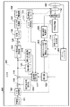
図1は、本発明の第1の実施形態に係る撮像装置の一例として、ビデオカメラの構成を示すブロック図である。なお、撮像装置として、ビデオカメラ以外にも、コンパクトデジタルカメラ、デジタル一眼レフカメラ、監視カメラ、またはカメラユニット付きのタブレットデバイスやゲーム機であっても良い。以下、図1の撮像装置100の各構成部とその動作について具体的に説明する。
(First embodiment)
FIG. 1 is a block diagram showing a configuration of a video camera as an example of an imaging apparatus according to the first embodiment of the present invention. In addition to the video camera, the imaging apparatus may be a compact digital camera, a digital single-lens reflex camera, a surveillance camera, or a tablet device or a game machine with a camera unit. Hereinafter, each component of the
角速度センサ101は、撮像装置100の振れを角速度信号として検出し、その角速度信号をA/D変換器102に供給する。A/D変換器102は、角速度センサ101からの角速度信号をデジタル化してμCOM103内部の減算器118に供給する。減算器118は、A/D変換器102の出力から固定基準値保持部104にあらかじめ保持されている固定基準値を減算して減算器119に供給する。この固定基準値とは、角速度センサの基準値をあらかじめ算出した値であり、例えば、角速度センサ101の仕様に基づいて決定される値、もしくは、撮像装置個々に調整等によって算出した値である。減算器119は、減算器118の出力から後述する基準値演算部117で算出した基準値を減算して、その差分をレンズ駆動量演算部105、振れ安定回数カウント部115および積分器121に供給する。以下では、減算器119の出力を角速度データと定義する。
The
レンズ駆動量演算部105は、上記の角速度データに基づいて、補正光学系109を駆動するための駆動量を算出し、減算器120に供給する。減算器120は、位置データをレンズ駆動量演算部105の出力から減算し、その結果である偏差データを制御フィルタ106に供給する。上記の位置データとは、補正光学系109の位置を検出する位置検出センサ110の出力をA/D変換器111にてA/D変換したデータである。
The lens driving
制御フィルタ106は、入力データを所定のゲインで増幅する増幅器、及び位相補償フィルタで構成されている。減算器120から供給された偏差データは、制御フィルタ106において増幅器及び位相補償フィルタによる信号処理が行われた後、パルス幅変調部107に出力される。
The
パルス幅変調部107は、制御フィルタ106を通過して供給されたデータを、パルス波のデューティー比を変化させる波形(即ちPWM波形)に変調して、モータ駆動部108に供給する。補正光学系109は、不図示の駆動用のボイス・コイル型モータがモータ駆動部108に駆動されることにより、光軸と垂直な方向に移動される。
The pulse
位置検出センサ110は、磁石とそれに対向する位置に備えられたホール・センサとからなり、補正光学系109の光軸と垂直な方向への移動量を検出し、その検出結果をA/D変換器111を介して、上述した減算器120に供給する。A/D変換器111の出力は、後述の基準値演算部117にも供給される。
The
補正光学系109は、例えば補正部材としてのシフトレンズを保持する補正レンズユニットであり、光軸と垂直な方向に移動されることにより光軸を偏向する。像振れ補正可能な光学系である。機器の振れを打ち消すように補正光学系109の移動が行われた結果、撮像装置100の振れによって生じる撮像面上の被写体の並進方向の像振れが補正された像が、撮像素子112に結像される。
The correction
撮像素子112は、補正光学系109を含む撮像光学系によって結像された被写体像を受光して撮像画像信号としての電気信号に変換し、信号処理部113に供給する。信号処理部113は、撮像素子112により得られた信号から、例えばNTSCフォーマットに準拠したビデオ信号(映像信号)を生成して動きベクトル検出部114に供給する。
The
動きベクトル検出部114は、信号処理部113で生成された現在の映像信号の画面に含まれる輝度信号と、不図示の画像メモリに格納された1フィールド前(または1フレーム前)の映像信号に含まれる輝度信号とに基づいて、画像の動きベクトルを検出する。動きベクトルの検出方法は、例えば従来提案されているブロックマッチング法などを用いる。
The motion
ブロックマッチング法は、撮像画像をブロックと呼ばれる領域に分割し、例えば1フレーム前の撮像画像と現在の撮像画像との類似箇所をブロック単位で検出する方法である。1フレーム前の撮像画像内の任意の範囲において、現在の撮像画像内の任意ブロックとの相関値が最も大きい個所を類似ブロック位置とする。現在の撮像画像内の任意ブロック位置と1フレーム前の撮像画像内の類似ブロック位置との変位量を求め、撮像画像のフレーム間の動き情報、すなわち動きベクトルを検出する。このブロック単位で検出した動きベクトルに基づいて、1フレーム単位の動きベクトルを検出する。 The block matching method is a method in which a captured image is divided into areas called blocks and, for example, a similar portion between the captured image one frame before and the current captured image is detected in units of blocks. In an arbitrary range in the captured image one frame before, a portion having the largest correlation value with an arbitrary block in the current captured image is set as a similar block position. A displacement amount between an arbitrary block position in the current captured image and a similar block position in the previous captured image is obtained, and motion information between frames of the captured image, that is, a motion vector is detected. Based on the motion vector detected in units of blocks, a motion vector in units of one frame is detected.
なお、ブロックマッチング法は動きベクトル検出部114における動きベクトル検出方法の一例であり、動きベクトル検出方法はブロックマッチング法以外の方法を用いてもよい。
The block matching method is an example of a motion vector detection method in the motion
また、動きベクトル検出部114は、動きベクトルの検出時に被写体のコントラストが低いか否かを判定する低コントラスト判定機能を有するものとする。コントラストが高い場合は任意範囲内の最大相関値と最小相関値の差が大きく(図2(A)を参照)、コントラストが低い場合は最大相関値と最小相関値の差が小さい(図2(B)参照)。この特徴を利用して、低コントラスト判定方法の一例として、任意の範囲内での相関値の最大値と最小値の差が所定値より小さい場合を低コントラストと判定する方法を用いる。なお、図2におけるブロックマッチング位置とは、任意の範囲内の端から水平方向に1画素単位で位置をずらしながらマッチングしていき、開始位置と逆側の端までのマッチングを行った位置を示す。ただし、実際のブロックマッチングは水平、垂直の両方向で行う。また、前述の低コントラスト判定方法において、被写体が低コントラストと判定された場合は、本実施形態においては、動きベクトルを出力する代わりに被写体が低コントラストであることを示すエラー出力を行うものとする。
The motion
動きベクトル検出部114によって検出された動きベクトルデータは、動きベクトル安定回数カウント部116と積分器122に供給される。積分器122は動きベクトルを積分し、基準値演算部117に供給する。
The motion vector data detected by the motion
振れ安定回数カウント部115は、装置の安定状態を判定する判定手段の一部をなす。振れ安定回数カウント部115は、所定期間にサンプリングした角速度データのうち、値が小さい、すなわち安定している回数をカウントすることができる。振れ安定回数カウント部115は、このカウントした回数に基づいて装置の安定状態を判定し、安定状態か否かの情報を基準値演算部117に供給する。
The shake stabilization
動きベクトル安定回数カウント部116は、装置の安定状態を判定する判定手段の一部をなす。動きベクトル安定回数カウント部116は、所定期間にサンプリングした動きベクトルのうち、値が小さい、すなわち安定している回数をカウントすることができる。動きベクトル安定回数カウント部116は、このカウントした回数に基づいて装置の安定状態を判定し、安定状態か否かの情報を基準値演算部117に供給する。
The motion vector stabilization
基準値演算部117は振れ安定回数カウント部115の出力と動きベクトル安定回数カウント部116の出力に基づいて角速度センサ101の基準値の算出方法を選択する。そして基準値演算部117は、積分器121の出力及び積分器122の出力に基づいて基準値を演算する。
The reference
基準値演算部117における基準値算出方法は、所定期間毎に以下の(i)〜(iii)のいずれかの方法である。
・基準値算出方法(i)
角速度データの積分値と動きベクトルの積分値を用いて、下記(式1)により基準値の算出を行う。
The reference value calculation method in the reference
・ Reference value calculation method (i)
Using the integrated value of the angular velocity data and the integrated value of the motion vector, the reference value is calculated by the following (Equation 1).
ref=d/dt{sensor_int−(correct_blur+remain_blur)} …(式1)
なお、d/dtは微分を示し、refは基準値を示す。また、sensor_int、correct_blur、remain_blurについては、後述する。
・基準値算出方法(ii)
角速度データの低周波成分を抽出する。なお、この低周波成分の抽出には、移動平均値やローパスフィルタなどを用いる。
・基準値算出方法(iii)
基準値算出を行わず、前回算出した基準値をそのまま基準値として減算器119に供給する。
ref = d / dt {sensor_int- (correct_blur + remain_blur)} (Expression 1)
Note that d / dt indicates differentiation, and ref indicates a reference value. Sensor_int, correct_blur, and remain_blur will be described later.
・ Reference value calculation method (ii)
Extract low frequency components of angular velocity data. For the extraction of the low frequency component, a moving average value, a low-pass filter, or the like is used.
・ Reference value calculation method (iii)
Without calculating the reference value, the previously calculated reference value is supplied as it is to the
なお、基準値演算部117において上記基準値算出方法(i)〜(iii)の中から基準値算出方法を選択する方法は、後述の基準値演算部117の一連の動作の説明において説明する。
Note that a method for selecting the reference value calculation method from the reference value calculation methods (i) to (iii) in the reference
ここで、基準値算出方法(i)についてより詳細に説明する。角速度データは、基準値に像振れ信号が重畳された値である。したがって、基準値をref、撮像装置100の振れ角速度をblur、所定期間の角速度データの積分値をsensor_intとすると、sensor_intは、以下の式で表すことができる。
Here, the reference value calculation method (i) will be described in more detail. The angular velocity data is a value obtained by superimposing an image blur signal on a reference value. Therefore, if the reference value is ref, the shake angular velocity of the
sensor_int=∫blur +∫ref …(式2)
ただし、sensor_intに関しては、単純に所定期間の角速度データの積分値であってもよいが、後述の所定の大きさ(第1の閾値)所定の大きさ未満である角速度データの積分値であってもよい。所定の大きさ未満である角速度データのみを積分する処理は、後述の図4のステップS205に該当する。
sensor_int = ∫blur + ∫ref… (Formula 2)
However, sensor_int may simply be an integrated value of angular velocity data for a predetermined period, but it is an integrated value of angular velocity data having a predetermined size (first threshold) described later that is less than a predetermined size. Also good. The process of integrating only angular velocity data that is less than a predetermined size corresponds to step S205 in FIG.
また、所定期間における、位置検出センサ110の出力の変化を、光軸の傾き角度に換算した値をcorrect_blurとする。更に、所定期間における、動きベクトル検出部114の出力の積算値をvector_intとする。Vector_intに関しても、sensor_intと同様に所定の大きさ(第2の閾値)未満の動きベクトルの積分値であってもよい。所定の大きさ未満である動きベクトルのみを積分する処理は、後述の図5のステップS303に該当する。
Further, a value obtained by converting the change in the output of the
vector_intは、所定期間の画像の動き量を示す値である。これを光軸の傾き角度に換算した値をremain_blurとすると、remain_blurは、以下のように算出することができる。撮像装置100の焦点距離をfとすると下の式が成立する。
vector_int is a value indicating the amount of motion of the image during a predetermined period. If the value obtained by converting this into the tilt angle of the optical axis is assumed to be remain_blur, the remaining_blur can be calculated as follows. If the focal length of the
vector_int=f×remain_blur
∴remain_blur=vector_int / f …(式3)
ここでcorrect_blurは、補正光学系109によって像振れ補正を行った角度を示す。そしてremain_blurは、補正光学系109によって補正しきれなかった角度を示す。よって、correct_blurとremain_blurとの和は、撮像装置100の振れ角度を示す。また、(式2)の右辺の∫blurも同様に、撮像装置100の振れ角度を示すため、以下の式が成立する。
vector_int = f × remain_blur
∴remain_blur = vector_int / f (Formula 3)
Here, correct_blur indicates an angle at which image blur correction is performed by the correction
∫blur=correct_blur+remain_blur …(式4)
よって、(式2)と(式4)より、以下の式が導出される。
∫blur = correct_blur + remain_blur (Formula 4)
Therefore, the following formula is derived from (Formula 2) and (Formula 4).
∫ref=sensor_int−(correct_blur+remain_blur) …(式5)
(式5)の両辺を微分すると、(式1)と一致することが分かる。
∫ref = sensor_int− (correct_blur + remain_blur) (Formula 5)
When both sides of (Formula 5) are differentiated, it can be seen that they coincide with (Formula 1).
ここで、(式5)によって基準値を算出する場合は、動きベクトル検出部114の検出周期よりも大きい期間(例えばNTSC方式では1/60秒)であればよい。この時間は基準値の変動周期よりも十分に速い周期であり、基準値の変動に遅延なく追従することが可能となる。 Here, when the reference value is calculated by (Equation 5), it may be a period longer than the detection cycle of the motion vector detection unit 114 (for example, 1/60 second in the NTSC system). This time is a period sufficiently faster than the reference value change period, and can follow the reference value change without delay.
しかし動きベクトル検出部114が補正光学系109によって補正しきれなかった像振れを検出できない場合には、(式4)は成立しなくなり、(式1)も同様に成立しない。このため、基準値算出方法(i)を用いて基準値を算出することができない。このとき、撮像装置100が静止状態あるいは定点撮影のように振れが小さい場合は、基準値算出方法(ii)を用いて基準値を算出する。このような場合には、角速度センサ101の出力から算出した基準値と真の基準値との誤差は無視できるほど小さく、算出した基準値を動きベクトルによる補正なしで用いても十分像振れ補正精度を保てると考えられる。
However, when the motion
基準値算出方法(i)を用いることができず、かつ装置の振れが大きい場合は、基準値算出方法(ii)を用いても算出した基準値に含まれる誤差が大きくなることが予想できる。この場合、基準値の算出を行わず前回算出した基準値をそのまま基準値演算部117の出力とすることで、誤った基準値算出が行われないようにする。
When the reference value calculation method (i) cannot be used and the apparatus shake is large, it can be expected that the error included in the calculated reference value will increase even if the reference value calculation method (ii) is used. In this case, the reference value calculated last time is used as it is as the output of the reference
以下では、基準値演算部117における動作について図3のフローチャートを用いて説明する。
Hereinafter, the operation of the reference
基準値演算部117の処理は所定時間の角速度センサ101の出力、動きベクトル検出部114の出力が安定しているか否かで基準値算出を行う方法を決定する。ステップS100では現在の経過時間が所定の時間(第5の閾値)以上か判定する。基準値演算部117は、不図示のタイマに基づいて時間計測を行う機能を有するものとし、撮像装置が通電された後、基準値演算部117の処理が実行される前に経過時間は0に設定されるものとする。
The process of the reference
ここで、所定の時間(第5の閾値)とは、角速度センサ101の出力、もしくは、動きベクトル検出部114の出力が安定状態か否かを判定するに十分な時間とする。ただし、所定の時間は、角速度センサ101の基準値変動に対して、基準値更新の遅延による像振れ補正精度低下が生じない程度の短い時間であることも同時に満たすものとする。現在の経過時間が所定の時間未満の場合は、ステップS101に処理を移し、時間計測を継続する。
Here, the predetermined time (fifth threshold) is a time sufficient to determine whether the output of the
ステップS100で現在の経過時間が所定の時間以上の場合、処理をステップS102に移行する。ステップS102では、振れ安定回数カウント部115のカウント値が所定の回数(第3の閾値)以上であるか判定し、所定の回数未満の場合は処理をステップS103に移行し、所定の回数以上の場合は処理をステップS104に移行する。ここで、所定の回数(第3の閾値)とは、角速度データが安定している状態が十分に継続していると判断できる値とする。
If the current elapsed time is greater than or equal to the predetermined time in step S100, the process proceeds to step S102. In step S102, it is determined whether the count value of the shake stabilization
ステップS103では、角速度データが安定しておらず、現在の角速度データを用いて基準値算出を行っても誤差を含む可能性があると判断し、基準値の算出を中止し、前回算出した値をそのまま基準値として用いる。このとき、計測時間を0にリセットする。 In step S103, it is determined that the angular velocity data is not stable, and there is a possibility of including an error even if the reference value calculation is performed using the current angular velocity data, the calculation of the reference value is stopped, and the previously calculated value As a reference value. At this time, the measurement time is reset to zero.
ステップS104では、動きベクトル安定回数カウント部116のカウント値が所定の回数(第4の閾値)以上であるか判定し、所定の回数未満の場合は処理をステップS106に移行し、所定の回数以上の場合は処理をステップS105に移行する。ここで、所定の回数(第4の閾値)とは、振れ安定回数カウント部115のカウント値と同じ考えに基づくものであり、動きベクトルが安定している状態が十分に継続していると判断できる値とする。
In step S104, it is determined whether the count value of the motion vector stable
ステップS105では、角速度データ、動きベクトルが十分に安定していると判断できたため、基準値算出方法(i)を採用する。ステップS106では基準値算出方法(ii)を採用する。これは、角速度データが基準値演算に用いるのに十分小さいが、動きベクトルが大きいため、ステップS105で示した基準値算出方法のうち、位置データと動きベクトルを用いた基準値の補正を行わないようにして、誤補正を回避する。 In step S105, since it can be determined that the angular velocity data and the motion vector are sufficiently stable, the reference value calculation method (i) is adopted. In step S106, the reference value calculation method (ii) is adopted. This is because the angular velocity data is sufficiently small to be used for the reference value calculation, but since the motion vector is large, the reference value is not corrected using the position data and the motion vector in the reference value calculation method shown in step S105. In this way, erroneous correction is avoided.
次に、振れ安定回数カウント部115における動作について図4のフローチャートを用いて説明する。
Next, the operation in the shake stabilization
振れ安定回数カウント部115の処理が開始されると、ステップS200では現在の経過時間が所定の時間以上か判定する。ここでの経過時間とは、基準値演算部117で計測している時間と同じものであればよく、必ずしも振れ安定回数カウント部115が時間計測を行う必要はない。例えば所定の時間以上になったタイミングで基準値演算部117から振れ安定回数カウント部115へ通知し、ステップS200は、基準値演算部117からの通知があるか否かを判定する処理であってもよい。
When the process of the shake stabilization
現在の経過時間が所定の時間未満である場合は、処理をステップS201に移行し、現在の経過時間が所定の時間以上である場合は、処理をステップS203に移行する。 If the current elapsed time is less than the predetermined time, the process proceeds to step S201. If the current elapsed time is equal to or longer than the predetermined time, the process proceeds to step S203.
ステップS201以降では、経過時間が所定の時間に達するまで、所定の時間間隔でサンプリングした角速度データが所定値に収まる回数をカウントし続ける。ステップS201では、角速度データが所定の大きさ未満か否かを判定し、所定の大きさ未満である場合は、処理をステップS202に移行し、所定の大きさ以上である場合は処理をステップS205に移行する。ステップS202では、振れ安定回数カウント値を1回加算する。ステップS205では、振れ安定回数カウントを行わない。さらに、現在の角速度データを積分器121での積分対象から外して、基準値演算用のデータとして使用されないようにする。これは、安定していない角速度データを用いて基準値を演算した場合に真の基準値との誤差が大きくなってしまうことを回避するための処理である。ここで、所定の大きさとは、角速度データを用いて基準値演算を行ったときに誤差が生じない程度の値とし、具体的には撮像装置をパンニングさせたときの角速度データが所定の大きさより大きくなる程度の値とする。
After step S201, the number of times that the angular velocity data sampled at a predetermined time interval falls within a predetermined value is continuously counted until the elapsed time reaches a predetermined time. In step S201, it is determined whether or not the angular velocity data is less than a predetermined size. If the angular velocity data is less than the predetermined size, the process proceeds to step S202. If the angular velocity data is greater than the predetermined size, the process proceeds to step S205. Migrate to In step S202, the shake stabilization frequency count value is added once. In step S205, the number of shake stabilization times is not counted. Further, the current angular velocity data is excluded from integration by the
ステップS203では、現在の振れ安定回数カウント値を基準値演算部117に対して出力し、処理をステップS204に移行する。ステップS204では振れ安定回数カウント値を0にリセットする。
In step S203, the current runout stabilization count value is output to the reference
この一連の処理によって、振れ安定回数カウント部115では、所定期間にサンプリングした角速度データのうち、値が小さい、すなわち安定している回数をカウントすることができる。
Through this series of processing, the shake stabilization
次に、動きベクトル安定回数カウント部116における動作について図5のフローチャートを用いて説明する。基本的には振れ安定回数カウント部115の処理と同じ考えに基づく。
Next, the operation in the motion vector stable
動きベクトル安定回数カウント部116の処理が開始されると、ステップS300では現在の経過時間が所定の時間(第5の閾値)以上か判定する。ここでの経過時間とは、基準値演算部117で計測している時間と同じものであればよく、必ずしも動きベクトル安定回数カウント部116が時間計測を行う必要はない。例えば所定の時間以上になったタイミングで基準値演算部117から動きベクトル安定回数カウント部116へ通知し、ステップS300は、基準値演算部117からの通知があるか否かを判定する処理であってもよい。
When the process of the motion vector stabilization
現在の経過時間が所定の時間未満である場合は、処理をステップS301に移行し、現在の経過時間が所定の時間以上である場合は、処理をステップS305に移行する。 If the current elapsed time is less than the predetermined time, the process proceeds to step S301. If the current elapsed time is equal to or longer than the predetermined time, the process proceeds to step S305.
ステップS301以降では、経過時間が所定の時間に達するまで、所定の時間間隔でサンプリングした動きベクトルが所定値に収まる回数をカウントし続ける。ただし、前述ように被写体が低コントラストの場合(動きベクトル検出部114の出力が動きベクトルでなく低コントラストを示すエラー出力の場合)、処理をステップS303に移行する。被写体が低コントラストでない場合は、処理をステップS302に移行し動きベクトルの大きさ判定を行う。ステップS302では、動きベクトルが所定の大きさ未満か否かを判定し、所定の大きさ未満である場合は、処理をステップS304に移行し、所定の大きさ以上である場合は処理をステップS303に移行する。ステップS303では、動きベクトル安定回数カウントを行わない。さらに、現在の動きベクトルを積分器122での積分対象から外して、基準値演算用のデータとして使用されないようにする。安定していない動きベクトルを用いて基準値を演算した場合に真の基準値との誤差が大きくなってしまうことを回避するための処理である。
After step S301, the number of times that the motion vector sampled at a predetermined time interval falls within a predetermined value is continuously counted until the elapsed time reaches a predetermined time. However, as described above, when the subject has low contrast (when the output of the motion
ステップS304では、動きベクトル安定回数カウント値を1回加算する。ここで、所定の大きさとは、角速度データが所定値に収まる回数と同じ考えに基づくものであり、動きベクトルを用いて基準値演算を行ったときに誤差が生じない程度の値とする。具体的には、補正光学系109による像振れ補正を行わず撮像装置をパンニングさせたときの動きベクトルが所定の大きさより大きくなる程度の値とする。
In step S304, the motion vector stability count value is added once. Here, the predetermined magnitude is based on the same idea as the number of times the angular velocity data falls within the predetermined value, and is a value that does not cause an error when the reference value calculation is performed using the motion vector. Specifically, the value is set such that the motion vector when the image pickup apparatus is panned without performing image blur correction by the correction
ステップS305では、現在の動きベクトル安定回数カウント値を基準値演算部117に対して出力し、処理をステップS306に移行する。ステップS306では動きベクトル安定回数カウント値を0にリセットする。
In step S305, the current motion vector stability count value is output to the reference
この一連の処理によって、動きベクトル安定回数カウント部116では、所定期間にサンプリングした動きベクトルのうち、値が小さい、すなわち安定している回数をカウントすることができる。
By this series of processing, the motion vector stable
以上説明してきたように、本発明の第1の実施形態においては、角速度センサ101の出力と動きベクトル検出部117の出力とが所定時間安定しているか否か判定し、その判定結果に基づいて適切な基準値算出方法を選択する。特に、角速度センサ101、動きベクトル検出部116の出力がともに安定している場合は、角速度センサ101の出力から算出した基準値に対し、位置検出センサ110の出力と動きベクトル検出部114の出力とによって誤差を修正する基準値演算を行う。これによって、角速度センサ101の出力のみを用いた場合よりも精度よく基準値算出ができ、像振れ補正精度低下を最小限に抑えることができる。
As described above, in the first embodiment of the present invention, it is determined whether or not the output of the
なお、この第1の実施形態においては、撮像装置の振れ検出に、角速度センサ101の出力を用いたが、これは種々の変形が可能である。例えば、加速度センサを用いてもよい。また、光学的な像振れ補正手段として、補正光学系109を例にとって説明したが、これに限定されるものではない。例えば、撮像素子1112を駆動する方法や、プリズムを用いる方法等、種々の像振れ補正手段を用いることができる。
In the first embodiment, the output of the
(第2の実施形態)
図6は、本発明の第2の実施形態に係る撮像装置の一例として、ビデオカメラの構成を示すブロック図である。なお、図6において、図1と同様の構成には、同じ符号を付し、説明を省略する。
(Second Embodiment)
FIG. 6 is a block diagram showing a configuration of a video camera as an example of an imaging apparatus according to the second embodiment of the present invention. In FIG. 6, the same components as those in FIG.
図6に示す撮像装置200は、図1に示す撮像装置100の構成に対し、焦点距離を変更可能な、ズーミング及びフォーカシング動作を行う撮像光学系203(ズームレンズ)、ズーム位置を検出するズームエンコーダ204を追加している。また、撮像素子112の露光時間の制御を行う露光時間制御部205(露光時間変更手段)がμCOM201に追加された構成となっている。なお、本実施形態において露光時間制御部205は現在の設定露光時間を動きベクトル安定回数カウント部202に供給する機能も備えるものとする。
An
動きベクトル安定回数カウント部202における動作について図7のフローチャートを用いて説明する。ただし、図7のフローチャートにおけるS400およびS402〜S404は図5におけるS300およびS302〜S304と同じ処理であるため、説明は省略する。
The operation in the motion vector stable
ステップS400で、現在の経過時間が所定の時間未満であると判定した場合は、処理をステップS401に移行する。ステップS401では、現在の撮影条件下で動きベクトル検出が可能か否かを判定し、動きベクトル検出が可能である条件を満たす場合のみ、処理をステップS402に移行する。前述した動きベクトルの検出可能である条件とは、少なくとも以下の3つを満たすものとする。 If it is determined in step S400 that the current elapsed time is less than the predetermined time, the process proceeds to step S401. In step S401, it is determined whether or not motion vector detection is possible under the current shooting conditions, and the process proceeds to step S402 only when the condition that motion vector detection is possible is satisfied. It is assumed that the above-described conditions for detecting a motion vector satisfy at least the following three conditions.
1つ目の条件は、第1の実施形態で示したように、動きベクトル検出部114が低コントラスト状態であることを検出していないことである。2つめの条件は、ズーム駆動中(焦点距離が変化している状態)でないことである。本実施形態では、ズームエンコーダ204により検出したズーム位置からズーム中か否かを判断する。ただし、ズーム中か否かの判定に関してはこれに限定するものでなく、例えばズームキーが操作されているか否かをハードウェアで検出し、これを動きベクトル安定回数カウント部202に通知するものであってもよい。ズーム中は動きベクトルが放射状に出力されるため、検出した動きベクトルから撮像画像の残存像振れを正確に算出することは困難であり、基準値算出に誤差を生じる恐れがある。3つめの条件は、露光時間が動きベクトル検出精度を確保できる時間未満(所定値未満)であることである。露光時間が動きベクトル検出精度を確保できる時間(所定時間)より長いと、被写体の動き、または撮像装置200の像振れによって、撮像画像内の被写体のエッジがぼやけてしまい、動きベクトル検出精度低下を招く恐れがある。この場合にも、上記2つの条件と同じく、検出した動きベクトルを撮像画像の残存像振れとして基準値演算に用いると誤差を生じる可能性がある。
The first condition is that, as shown in the first embodiment, the motion
上記3つのうち、1つでも満たしていなければ、検出した動きベクトルを基準値算出に用いないようにする。 If at least one of the three is not satisfied, the detected motion vector is not used for calculating the reference value.
以上のように、本発明の第2の実施形態においては、第1の実施形態の構成に加えて、ズームエンコーダ204、露光時間制御部205を追加し、動きベクトルが検出可能な撮影条件にあるか否かの判定も行う構成とした。これによって、単純に動きベクトルの大きさで基準値演算を行うことが可能か否かを判定する場合と比べ、更に基準値の誤算出を回避することが可能となる。なお、この第2の実施形態においては、動きベクトルの検出可能条件に3つの条件を示したが、動きベクトルの誤検出を回避する条件は、これに限定されるものではない。
As described above, in the second embodiment of the present invention, in addition to the configuration of the first embodiment, the
以上、本発明をその好適な実施形態に基づいて詳述してきたが、本発明はこれら特定の実施形態に限られるものではなく、この発明の要旨を逸脱しない範囲の様々な形態も本発明に含まれる。上述の実施形態の一部を適宜組み合わせてもよい。 Although the present invention has been described in detail based on preferred embodiments thereof, the present invention is not limited to these specific embodiments, and various forms within the scope of the present invention are also included in the present invention. included. A part of the above-described embodiments may be appropriately combined.
(他の実施形態)
また、本発明は、以下の処理を実行することによっても実現される。即ち、上述した実施形態の機能を実現するソフトウェア(プログラム)を、ネットワーク又は各種記憶媒体を介してシステム或いは装置に供給し、そのシステム或いは装置のコンピュータ(またはCPUやMPU等)がプログラムを読み出して実行する処理である。
(Other embodiments)
The present invention can also be realized by executing the following processing. That is, software (program) that realizes the functions of the above-described embodiments is supplied to a system or apparatus via a network or various storage media, and a computer (or CPU, MPU, etc.) of the system or apparatus reads the program. It is a process to be executed.
Claims (9)
撮像装置の振れを検出し、前記検出した振れに基づく値を出力する振れ検出手段と、
前記振れ検出手段の出力に対して基準値を演算する基準値演算手段と、
前記振れ検出手段の出力と前記基準値演算手段で演算した基準値との差分に基づいて、撮像装置の振れ量を演算し、演算した振れ量を出力する振れ量演算手段と、
前記振れ量演算手段の出力に基づいて、撮像画像に発生する像振れを補正する像振れ補正手段と、
撮像画像から画面の動きを示す動きベクトルを検出し、検出した動きベクトルを出力する動きベクトル検出手段と、
前記振れ検出手段と前記動きベクトル検出手段との出力に基づいて装置の安定状態を判定する判定手段と、
前記基準値演算手段は、前記判定手段によって装置が安定状態にあると判定されたときに、前記振れ量演算手段の出力と前記動きベクトル検出手段の出力に基づいて前記基準値を演算することを特徴とする撮像装置。 Imaging means for receiving a subject image and generating a captured image;
A shake detection unit that detects a shake of the imaging apparatus and outputs a value based on the detected shake;
Reference value calculation means for calculating a reference value for the output of the shake detection means;
Based on the difference between the output of the shake detection means and the reference value calculated by the reference value calculation means, the shake amount calculation means for calculating the shake amount of the imaging device and outputting the calculated shake amount;
An image blur correction unit that corrects an image blur generated in the captured image based on an output of the blur amount calculation unit;
Motion vector detection means for detecting a motion vector indicating the motion of the screen from the captured image and outputting the detected motion vector;
A determination unit that determines a stable state of the apparatus based on outputs of the shake detection unit and the motion vector detection unit;
The reference value calculation means calculates the reference value based on the output of the shake amount calculation means and the output of the motion vector detection means when the determination means determines that the apparatus is in a stable state. An imaging device that is characterized.
前記動きベクトル検出手段の出力を前記所定の時間間隔でサンプリングし、サンプリングした動きベクトルの大きさが所定の大きさ未満である場合のみカウントする動きベクトル安定回数カウント手段と、を備え、
前記基準値演算手段は、所定の期間における前記振れ安定回数カウント手段でのカウント値が所定の回数以上であり、かつ、前記所定の期間における前記動きベクトル安定回数カウント手段でのカウント値が所定の回数以上である場合に、前記振れ量演算手段の出力と前記動きベクトル検出手段の出力に基づいて前記基準値を演算することを特徴とする請求項1に記載の撮像装置。 The determination means samples the output of the shake amount calculation means at a predetermined time interval, and counts only when the sampled shake amount is less than a predetermined magnitude.
Sampling the output of the motion vector detection means at the predetermined time interval and counting only when the sampled motion vector is less than a predetermined size, a motion vector stable frequency counting means,
The reference value calculating means has a count value in the shake stabilization frequency counting means in a predetermined period equal to or greater than a predetermined number, and a count value in the motion vector stable frequency count means in the predetermined period is a predetermined value. 2. The imaging apparatus according to claim 1, wherein the reference value is calculated based on an output of the shake amount calculation unit and an output of the motion vector detection unit when the number is equal to or greater than the number of times.
前記振れ検出手段の出力に対して基準値を演算する基準値演算工程と、
前記振れ検出手段の出力と前記基準値演算工程で演算した基準値との差分に基づいて、撮像装置の振れ量を演算し、演算した振れ量を出力する振れ量演算工程と、
前記振れ量演算工程での出力に基づいて、撮像画像に発生する像振れを補正する像振れ補正工程と、
撮像画像から画面の動きを示す動きベクトルを検出し、検出した動きベクトルを出力する動きベクトル検出工程と、
前記振れ検出工程と前記動きベクトル検出工程からの出力に基づいて装置の安定状態を判定する判定工程と、を有し、
前記基準値演算工程は、前記判定工程によって装置が安定状態にあると判定されたときに、前記振れ量演算工程からの出力と前記動きベクトル検出工程からの出力に基づいて前記基準値を演算することを特徴とする撮像装置の制御方法。 A method of controlling an imaging apparatus comprising: an imaging unit that receives a subject image and generates a captured image; and a shake detection unit that detects a shake of the imaging apparatus and outputs a value based on the detected shake.
A reference value calculation step of calculating a reference value for the output of the shake detection means;
Based on the difference between the output of the shake detection means and the reference value calculated in the reference value calculation step, the shake amount calculation step of calculating the shake amount of the imaging device and outputting the calculated shake amount;
Based on the output in the shake amount calculation step, an image shake correction step for correcting image shake that occurs in the captured image;
A motion vector detection step of detecting a motion vector indicating the motion of the screen from the captured image and outputting the detected motion vector;
A determination step of determining a stable state of the apparatus based on outputs from the shake detection step and the motion vector detection step,
The reference value calculation step calculates the reference value based on an output from the shake amount calculation step and an output from the motion vector detection step when the determination step determines that the apparatus is in a stable state. And a method of controlling the imaging apparatus.
前記動きベクトル検出工程での出力を前記所定の時間間隔でサンプリングし、サンプリングした動きベクトルの大きさが所定の大きさ未満である場合のみカウントする動きベクトル安定回数カウント工程と、を備え、
前記基準値演算工程は、所定の期間における前記振れ安定回数カウント工程でのカウント値が所定の回数以上であり、かつ、前記所定の期間における前記動きベクトル安定回数カウント工程でのカウント値が所定の回数以上である場合に、前記振れ量演算工程での出力と前記動きベクトル検出工程での出力に基づいて前記基準値を演算することを特徴とする撮像装置の制御方法。 The determination step samples the output in the shake amount calculation step at a predetermined time interval, and counts only when the sampled shake amount is less than a predetermined size.
Sampling the output of the motion vector detection step at the predetermined time interval, and counting only when the sampled motion vector is less than a predetermined size, a motion vector stable frequency counting step,
In the reference value calculating step, a count value in the shake stabilization frequency counting step in a predetermined period is equal to or greater than a predetermined number, and a count value in the motion vector stable frequency counting step in the predetermined period is a predetermined value. A control method for an image pickup apparatus, wherein the reference value is calculated based on an output in the shake amount calculation step and an output in the motion vector detection step when the number is equal to or greater than the number of times.
Priority Applications (1)
| Application Number | Priority Date | Filing Date | Title |
|---|---|---|---|
| JP2012286169A JP2014126859A (en) | 2012-12-27 | 2012-12-27 | Imaging apparatus, method of controlling the same, program and storage medium |
Applications Claiming Priority (1)
| Application Number | Priority Date | Filing Date | Title |
|---|---|---|---|
| JP2012286169A JP2014126859A (en) | 2012-12-27 | 2012-12-27 | Imaging apparatus, method of controlling the same, program and storage medium |
Publications (1)
| Publication Number | Publication Date |
|---|---|
| JP2014126859A true JP2014126859A (en) | 2014-07-07 |
Family
ID=51406346
Family Applications (1)
| Application Number | Title | Priority Date | Filing Date |
|---|---|---|---|
| JP2012286169A Pending JP2014126859A (en) | 2012-12-27 | 2012-12-27 | Imaging apparatus, method of controlling the same, program and storage medium |
Country Status (1)
| Country | Link |
|---|---|
| JP (1) | JP2014126859A (en) |
Cited By (3)
| Publication number | Priority date | Publication date | Assignee | Title |
|---|---|---|---|---|
| CN107277312A (en) * | 2016-03-31 | 2017-10-20 | 佳能株式会社 | Fittings equipment, picture pick-up device, control device, lens apparatus and control method |
| CN109791342A (en) * | 2016-09-15 | 2019-05-21 | 富士胶片株式会社 | Shaking detection device, shake correction device, photographic device and the blur detecting method of photographic device |
| JP2019086800A (en) * | 2019-02-21 | 2019-06-06 | 株式会社ニコン | Tremor correction device and image capturing device |
-
2012
- 2012-12-27 JP JP2012286169A patent/JP2014126859A/en active Pending
Cited By (8)
| Publication number | Priority date | Publication date | Assignee | Title |
|---|---|---|---|---|
| CN107277312A (en) * | 2016-03-31 | 2017-10-20 | 佳能株式会社 | Fittings equipment, picture pick-up device, control device, lens apparatus and control method |
| GB2567943A (en) * | 2016-03-31 | 2019-05-01 | Canon Kk | Image-capturing apparatus, control apparatus, lens apparatus, control method, computer program and storage medium storing computer program |
| GB2567943B (en) * | 2016-03-31 | 2020-11-04 | Canon Kk | Image-capturing apparatus, control apparatus, lens apparatus, control method, computer program and storage medium storing computer program |
| US10944895B2 (en) | 2016-03-31 | 2021-03-09 | Canon Kabushiki Kaisha | Accessory apparatus, image-capturing apparatus, control apparatus, lens apparatus, control method, computer program and storage medium storing computer program |
| CN107277312B (en) * | 2016-03-31 | 2021-05-18 | 佳能株式会社 | Accessory apparatus, control method thereof, image pickup apparatus, and control method thereof |
| CN109791342A (en) * | 2016-09-15 | 2019-05-21 | 富士胶片株式会社 | Shaking detection device, shake correction device, photographic device and the blur detecting method of photographic device |
| CN109791342B (en) * | 2016-09-15 | 2021-02-02 | 富士胶片株式会社 | Image pickup apparatus, and shake detection apparatus, shake correction apparatus, and shake detection method therefor |
| JP2019086800A (en) * | 2019-02-21 | 2019-06-06 | 株式会社ニコン | Tremor correction device and image capturing device |
Similar Documents
| Publication | Publication Date | Title |
|---|---|---|
| JP5501119B2 (en) | Imaging apparatus and control method thereof | |
| US9626743B2 (en) | Image stabilization apparatus, method of controlling the same, image capturing apparatus, lens apparatus, and storage medium | |
| US9170429B2 (en) | Optical apparatus and image capturing apparatus, and method of controlling the same and storage medium | |
| US10101593B2 (en) | Optical apparatus, control method thereof and storage medium | |
| JP6674264B2 (en) | Image blur detection apparatus and method, and imaging apparatus | |
| US10230897B2 (en) | Control apparatus, image capturing apparatus, lens apparatus, control method, and non-transitory computer-readable storage medium | |
| JP2015031780A (en) | Image shake correction device and control method for the same, lens barrel, optical device and imaging device | |
| JP6518452B2 (en) | Imaging apparatus and imaging method | |
| JP2015089108A (en) | Imaging device and imaging method | |
| US10250808B2 (en) | Imaging apparatus and control method therefor | |
| JP6995561B2 (en) | Image stabilization device and its control method, image pickup device | |
| JP2011139169A (en) | Imaging apparatus | |
| JP2015233248A (en) | Imaging apparatus and imaging method | |
| JP2012058545A (en) | Imaging device | |
| JP2014216864A (en) | Imaging device and control method, program and storage medium therefor | |
| JP6543946B2 (en) | Shake correction device, camera and electronic device | |
| US9811891B2 (en) | Image shake correction device, optical apparatus, imaging apparatus, and control method | |
| JP4869579B2 (en) | Blur correction device and camera system | |
| US11570361B2 (en) | Lens unit, imaging device, control methods thereof, and storage medium | |
| JP6824710B2 (en) | Zoom control device and zoom control method, imaging device | |
| JP6039212B2 (en) | Image blur correction apparatus, imaging apparatus, and image blur correction apparatus control method | |
| JP2014126859A (en) | Imaging apparatus, method of controlling the same, program and storage medium | |
| JP2010271379A (en) | Imaging device | |
| JP5699806B2 (en) | Imaging device | |
| JP2005141207A (en) | Blurring correcting apparatus and camera system |