JP6039212B2 - Image blur correction apparatus, imaging apparatus, and image blur correction apparatus control method - Google Patents
Image blur correction apparatus, imaging apparatus, and image blur correction apparatus control method Download PDFInfo
- Publication number
- JP6039212B2 JP6039212B2 JP2012076404A JP2012076404A JP6039212B2 JP 6039212 B2 JP6039212 B2 JP 6039212B2 JP 2012076404 A JP2012076404 A JP 2012076404A JP 2012076404 A JP2012076404 A JP 2012076404A JP 6039212 B2 JP6039212 B2 JP 6039212B2
- Authority
- JP
- Japan
- Prior art keywords
- reference value
- image blur
- shake
- correction
- amount
- Prior art date
- Legal status (The legal status is an assumption and is not a legal conclusion. Google has not performed a legal analysis and makes no representation as to the accuracy of the status listed.)
- Active
Links
Images


Description
本発明は、装置の振れを検出して撮影画像の像ブレを補正する像ブレ補正技術に関するものである。 The present invention relates to an image blur correction technique for detecting a shake of an apparatus and correcting an image blur of a captured image.
従来、カメラ等の撮像装置に搭載されている手振れ補正システムにおいては、加速度、角加速度、角速度、角変位等を検出するセンサによって装置の振動を検出し、振れ量に応じて光学的または電子的に像ブレを補正する。振動検出には角速度を検出するジャイロセンサが一般的に使用される。ジャイロセンサは、温度変化等によって生じるDCオフセットやドリフトの影響が大きいため、それらの成分を検出信号から除去する必要がある。オフセット成分の除去方法として、ジャイロセンサ出力の平均値を算出して基準値とする方法がある。また、画像動きベクトルを別途に検出して基準値の算出にフィードバックすることで、パンニング等によるカメラの動きの影響を受け難くする方法が提案されている(特許文献1参照)。 Conventionally, in a camera shake correction system mounted on an imaging device such as a camera, the vibration of the device is detected by a sensor that detects acceleration, angular acceleration, angular velocity, angular displacement, and the like, and optical or electronic depending on the amount of shake. Correct image blur. A gyro sensor that detects angular velocity is generally used for vibration detection. Since the gyro sensor is greatly affected by DC offset and drift caused by temperature changes and the like, it is necessary to remove these components from the detection signal. As a method for removing the offset component, there is a method of calculating an average value of the gyro sensor output as a reference value. In addition, a method has been proposed in which an image motion vector is separately detected and fed back to the calculation of a reference value so as to be less affected by camera motion due to panning or the like (see Patent Document 1).
従来の像ブレ補正装置では、ジャイロセンサの出力変動の影響に対する敏感度について考慮されていないため、以下の問題が生じ得る。
手振れ補正における前記基準値の精度は、焦点距離や撮影状況等によって変化する。基準値の精度を常に一定した制御の場合、撮影状況によっては必要以上の精度で補正が行われる場合があり、処理効率の面で冗長な状況が生じる。例えば、ユーザが歩き撮り等を行う状況のように、大きな揺れや振れが生じる場合には基準値の正確な算出が困難である。このような状況では、基準値の精度を過度に要求しなくても像ブレ補正に対する影響は少ない。他方、ユーザがテレ側(望遠側)の設定で固定の被写体を撮影する状況等では、基準値の精度が厳しく要求され、基準値の算出精度が像ブレ補正の性能に与える影響が大きい。
本発明の目的は、像ブレ補正において振れ検出信号に係る基準値の算出及び更新が必要以上の頻度で行われないように防止することである。
In the conventional image blur correction apparatus, the sensitivity to the influence of the output fluctuation of the gyro sensor is not taken into consideration, so the following problem may occur.
The accuracy of the reference value in camera shake correction varies depending on the focal length, shooting conditions, and the like. In the case of control in which the accuracy of the reference value is always constant, correction may be performed with an accuracy higher than necessary depending on the shooting situation, and a redundant situation occurs in terms of processing efficiency. For example, it is difficult to accurately calculate the reference value when a large shake or shake occurs, such as a situation where a user takes a walk. In such a situation, there is little influence on the image blur correction even if the accuracy of the reference value is not excessively required. On the other hand, in a situation where the user is shooting a fixed subject with the setting on the telephoto side (telephoto side), the accuracy of the reference value is strictly required, and the calculation accuracy of the reference value greatly affects the image blur correction performance.
An object of the present invention is to prevent the calculation and update of a reference value relating to a shake detection signal from being performed more frequently than necessary in image blur correction.
本発明の一実施形態の像ブレ補正装置は、振れ検出信号から補正量を算出して像ブレを補正する像ブレ補正装置であって、撮像装置の振れ状態を検出する振れ検出手段の出力及び動きベクトル検出手段の出力の少なくとも1つを用いて前記撮像装置の振れの振幅量を判別する判別手段と、前記振れ検出信号に係る基準値をオフセット成分から算出して更新する処理を行う基準値算出手段と、前記振れ検出信号から前記基準値を減算した信号を取得して像ブレの補正量を算出する補正量算出手段と、前記補正量算出手段が算出する補正量に従って像ブレを補正する制御手段を備える。前記基準値算出手段は、前記振幅量に基いて前記基準値を更新する際の敏感度を設定し、新たに算出した基準値と既に設定されている基準値との比率を算出し、新たに算出した前記比率が前記敏感度より大きく、且つ、前記振幅量が所定の閾値以下であると判別された場合、前記既に設定されている基準値を更新する。前記基準値算出手段は、前記判別手段によって前記振幅量が前記所定の閾値より大きいと判別された場合、前記振幅量が前記所定の閾値以下であると判別された場合に比べて、前記敏感度を大きくする。
An image blur correction apparatus according to an embodiment of the present invention is an image blur correction apparatus that corrects an image blur by calculating a correction amount from a shake detection signal, and includes an output of a shake detection unit that detects a shake state of the imaging apparatus, and A discriminating unit that discriminates an amplitude amount of shake of the imaging apparatus using at least one of outputs of the motion vector detecting unit; and a reference value that performs processing of calculating and updating a reference value related to the shake detection signal from an offset component A calculation unit, a correction amount calculation unit that obtains a signal obtained by subtracting the reference value from the shake detection signal and calculates a correction amount of the image blur, and corrects the image blur according to the correction amount calculated by the correction amount calculation unit. Ru and a control means. The reference value calculation means sets the sensitivity at the time of updating the reference value based on the amplitude amount, calculates the ratio between the newly calculated reference value and the already set reference value, and newly When it is determined that the calculated ratio is greater than the sensitivity and the amplitude amount is equal to or less than a predetermined threshold, the already set reference value is updated. The reference value calculating means is more sensitive when the determining means determines that the amplitude amount is greater than the predetermined threshold than when determining that the amplitude amount is less than or equal to the predetermined threshold. Increase
本発明によれば、像ブレ補正において振れ検出信号に係る基準値の算出及び更新が必要以上の頻度で行われないように防止できる。 According to the present invention, it is possible to prevent the calculation and update of the reference value related to the shake detection signal from being performed more frequently than necessary in the image blur correction.
以下、本発明の各実施形態に係る像ブレ補正装置及びこれを備えた撮像装置について、添付図面を参照して詳細に説明する。本発明は、デジタルビデオカメラ、レンズ交換可能なデジタル一眼レフカメラ、携帯電話等に搭載される撮像装置に幅広く適用可能である。 Hereinafter, an image blur correction apparatus and an imaging apparatus including the same according to each embodiment of the present invention will be described in detail with reference to the accompanying drawings. The present invention can be widely applied to imaging devices mounted on digital video cameras, digital SLR cameras with interchangeable lenses, mobile phones, and the like.
[第1実施形態]
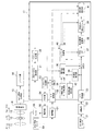
図1は、撮像装置のシステム構成例を示すブロック図であり、像ブレ補正に関係する構成要素を示す。図1の撮像光学系にて、変倍レンズ群(以下、ズームレンズという)11は焦点距離の変更により変倍動作を行う。ブレ補正光学系を構成するレンズ群(以下、シフトレンズという)12は光軸に対して垂直な方向に移動可能であり、補正用光学部材の駆動により像ブレを補正する。レンズ群(以下、フォーカスレンズという)13は、焦点調節機能と、変倍動作による焦点面の移動を補正するいわゆるコンペンセーション機能を兼ね備える。
[First Embodiment]
FIG. 1 is a block diagram illustrating a system configuration example of an imaging apparatus, and illustrates components related to image blur correction. In the imaging optical system of FIG. 1, a variable power lens group (hereinafter referred to as a zoom lens) 11 performs a variable power operation by changing the focal length. A lens group (hereinafter referred to as a shift lens) 12 constituting the blur correction optical system is movable in a direction perpendicular to the optical axis, and corrects image blur by driving a correction optical member. The lens group (hereinafter referred to as a focus lens) 13 has both a focus adjustment function and a so-called compensation function for correcting the movement of the focal plane due to the zooming operation.
撮像素子14はレンズ群11,12,13を通して結像した光を光電変換する。撮像素子14には、例えばCCD(電荷結合素子)やCMOS(相補型金属酸化膜半導体)等を用いたイメージセンサが使用される。カメラ信号処理部15は、CDS(Co-related Double Sampling:相関二重サンプリング)回路、AGC(Automatic Gain Control)回路、デジタル信号処理回路等から構成される。このデジタル信号処理回路は、A(Analog)/D(Digital)変換器によりアナログ撮像信号をデジタル信号に変換し、ガンマ補正、ホワイトバランス調整等、所定の信号処理を施したデジタル映像信号を生成する。レコーダ部16は、メモリカードなどの記録媒体に映像信号を記録する処理及び制御を行う。この他、図示は省略するが、映像信号に従って画像を表示する表示装置(液晶表示パネルや電子ビューファインダ等)、及びその制御回路等が設けられている。
The
システム制御部17は撮像装置のシステム全体を制御し、演算部を備える。動きベクトル検出部21は、カメラ信号処理部15で信号処理された画像信号を取得して1フレームごと、または1フィールドごとの動きベクトルを検出する。動きベクトルの検出方法は、ブロックマッチング法や特徴点を使用する方法など、公知の方法を使用する。ベクトル積分部22は、動きベクトル検出部21が検出した1フレーム間または1フィールド間の動きベクトルを積算して画像の動き量を算出する。
The
振れ検出センサ31は手振れや体の揺れ等によって生じる撮像装置の振れを検出して検出信号を出力する。振れ検出センサ31は、例えば角速度センサであり、振動検出用のジャイロセンサ等が使用される。増幅器32は、振れ検出センサ31が出力する角速度検出信号を増幅する。A/D変換器33は増幅器32のアナログ出力信号を、システム制御部17内で処理可能なデジタル信号に変換する。角速度積分部34は、A/D変換器33の出力、つまり、振れ検出センサ31の増幅信号に係るA/D変換値を積算して振れ角度情報を算出する。
The
手振れ補正モード判別部35は、手振れ補正モードの判別処理を行う。本実施形態では、例えば、ユーザが移動せずにその場で通常の撮影を行う場合の第1モード(以下、通常モードという)と、撮影する時に生じるような大きな像ブレを補正する第2モード(以下、歩き撮りモードという)を、少なくとも有する。手振れ補正モード判別部35は、判別した手振れ補正モードの情報を基準値算出部36に出力する。なお、手振れ補正モードの設定や切り替えについては、撮像装置に設けたモード設定手段(不図示)を使ってユーザが手動操作で行ってもよく、または、撮像装置が動きベクトルや角速度信号等の検出情報に基づいて自動的に行ってもよい。例えば、手振れ補正モード判別部35は、振れ検出センサ31の出力に基づく信号の変化が、予め定めた周波数や振幅に相当する閾値より大きいと判定しときに、撮影者が移動していると判定し、第2モード(歩き撮りモード)であると判定する。また、別の例として、焦点距離によって判断してもよい。焦点距離(ズーム位置)がワイド側である場合は、撮影画角が広いため、移動しながらの撮影に適している。よって、焦点距離(ズーム位置)がワイド側である場合に第2モードと判定したり、焦点距離(ズーム位置)がワイド側である場合であって、かつ振れ検出センサ31の出力に基づいた信号の変化が大きい場合に第2モードと判定することができる。
The camera shake correction
基準値算出部36は、振れ検出センサ31のオフセット電圧分となる基準値(安定状態時のセンサ出力に相当する)を算出する。基準値算出部36は、角速度積分部34で算出される振れ角度情報及びベクトル積分部22で算出した画像の動き量に基づいて、撮像装置本体の安定度を判定して振れ検出センサ31の基準値を更新する。その際、基準値算出部36は手振れ補正モード判別部35による手振れ補正モードの判別結果に応じて、基準値更新の敏感度を変更する。ここで敏感度(Sと記す)とは、振れ検出センサ31の出力変動に伴う基準値の変動に対して基準値更新の応答性を制御するための値である。敏感度Sの値が小さく設定されると、基準値の算出及び更新処理の精度を高めることができ、敏感度Sの値が大きく設定されると、基準値の更新精度を高めるよりも、誤判定による影響を受け難くすることができる。更新処理の詳細については後述する。
The reference
A/D変換器33のデジタル出力信号は第1減算部DEC1に送られて、基準値算出部36で算出された基準値が減算される。減算結果を示す信号はハイパスフィルタ(以下、HPFと略記する)37及びパンニング判定部40に送られる。HPF37は、周波数特性を可変し得る機能を有しており、第1減算部DEC1からの角速度信号が入力され、所定周波数以下の低周波成分を遮断した信号を出力する。焦点距離演算部38は、HPF37を通過した角速度信号が入力され、該信号から焦点距離に応じた光軸偏心角の変化量に変換する。周波数特性を可変し得るローパスフィルタ(以下、LPFと略記する)を用いた積分器39は、焦点距離演算部38の出力を積分して角変位量を算出する。パンニング判定部40は、第1減算部DEC1にてオフセット成分を除去された角速度信号、ベクトル積分部22が出力する画像の動き量、及び積分器39が出力する角変位量に基づいて撮像装置本体のパンニング操作について判定する。パンニング操作が行われていると判定された場合、パンニング判定部40はHPF37及び積分器39のLPFの周波数特性を変更することによりパンニング制御を行う。なお、パンニング判定部40に加えて、チルティング判定部を設ける形態も可能であり、チルティング操作に応じた像ブレ補正制御が行われる。補正量算出部41は、パンニング判定部40の判定結果と、積分器39の出力する角変位量の情報に基づいて像ブレ補正量(補正目標値)を算出して、第2減算部DEC2に出力する。
The digital output signal of the A /
位置検出センサ50(例えばホールセンサ)はシフトレンズ12の位置を検出する。増幅器51は、位置検出センサ50の検出信号を増幅し、A/D変換器52は、増幅器51からのアナログ信号をデジタル信号に変換して、システム制御部17内で処理可能な信号とする。A/D変換器52の出力は第2減算部DECに送られる。第2減算部DEC2は、補正量算出部41が算出した像ブレの補正目標値から、A/D変換器52の出力する現在の位置データを減算し、差分情報をシフトレンズ制御部53に出力する。シフトレンズ制御部53は、差分情報からシフトレンズ12の駆動制御量を算出して、制御信号をPWM(パルス幅変調)部54に出力する。PWM部54は、シフトレンズ制御部53からの制御信号に従ってパルス幅を可変制御してアナログ信号を出力する。駆動部55は、PWM部54の出力信号に従ってモータ56を駆動し、シフトレンズ12を移動させる。駆動用のモータ56は、例えばVCM(ボイスコイルモータ)等である。
なお、図1に示す焦点距離判別部42については後述の第3実施形態にて説明し、第1実施形態ではないものとする。
A position detection sensor 50 (for example, a hall sensor) detects the position of the shift lens 12. The
The focal
次に、本実施形態で行う振れ検出センサ31の基準値算出及び更新処理について説明する。
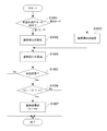
図2は処理例を示すフローチャートである。本処理は、像ブレ補正装置の手振れ補正の設定がON状態である場合に、所定の周期(例えば画像データの取り込み周期等)で基準値算出部36が繰り返し実行する。なお、このことは以下に説明する他の実施形態でも同様である。
Next, reference value calculation and update processing of the
FIG. 2 is a flowchart showing a processing example. This process is repeatedly executed by the reference
まずS1001は、設定された手振れ補正モードが第1モード(通常モード)であるか、または第2モード(歩き撮りモード)であるかの判別処理である。例えば、手振れ補正モード判別部35は、振れ検出センサ31の出力に基づく信号の変化が、予め定めた周波数や振幅に相当する閾値より大きいと判定したときに、撮影者の移動などにより大きな振れ加わっていると判定し、第2モードと判定する。ユーザが移動せずにその場で通常の撮影を行う場合の第1モード(通常モード)であると、手振れ補正モード判別部35が判断した場合、基準値算出部36は第1モードの判別結果を得てS1002に処理を進める。また、手振れ補正モード判別部35が、歩行撮影時に生じるような大きな像ブレを補正する第2モード(歩き撮りモード)であると判断した場合、基準値算出部36は第2モードの判別結果を得てS1003に処理を進める。S1002では、基準値を更新する際の敏感度Sとして、第1モード時の敏感度Saが設定される。一方、S1003では、基準値更新の敏感度Sとして、第2モード時の敏感度Sbが設定される。Sb値はSa値より大きい。よって、第2モード時の敏感度をSbとすることで、第1モード時よりも、基準値の更新精度の敏感度を制限して、より誤判定による影響を受け難くすることができる。この敏感度の設定については図3を用いて後述する。
First, S1001 is a process of determining whether the set camera shake correction mode is the first mode (normal mode) or the second mode (walking mode). For example, when the camera shake correction
次にS1004では振れ検出センサ31の基準値Vnが算出される。S1005は、撮像装置本体の状態判定処理である。撮像装置本体が安定状態であるか否かについて判定され、安定状態であればS1006に処理を進め、安定状態でなければ、そのまま処理を終了する。安定状態の判定処理では、例えば角速度積分部34から得られる振れ角度情報と、ベクトル積分部22から得られる画像の動き量について、それぞれの単位時間当りの変化量(振幅量)が所定の閾値と比較される。これらの変化量が閾値以下である場合に安定状態と判定される。次にS1006では、S1004で算出した基準値Vnと、現時点で設定されている基準値(Vと記す)との比率(Vn/V)が算出される。この比率は基準値の変動量を表しており、敏感度Sと比較される。つまり、Vn/Vの値は、第1モードの場合に敏感度Saと比較され、また、第2モードの場合に敏感度Sbと比較される。Vn/Vの値がSa値またはSb値より大きい場合、S1007に進み、S1004で算出した基準値Vnが新たに基準値Vとして更新される。一方、S1006でVn/Vの値がSa値以下、またはSb値以下の場合、基準値Vは変更されずに処理が終了する。
Next, in S1004, a reference value Vn for the
図3は、ユーザが撮像装置を手持ちの状態で撮影する場合に手振れの検出信号(振れ検出センサ31の出力信号)を例示した概念図である。図3(A)は、固定の被写体を狙った通常撮影における角速度検出信号の時間的変化を示し、振れ検出センサ31の出力信号は比較的小さい振幅の信号である。これに対して図3(B)は、ユーザが歩行しながら撮影した、いわゆる歩き撮りなどの大きな振れにおける角速度検出信号の時間的変化を示す。この場合、撮像装置には大きな振れが生じるため、振れ検出センサ31の出力信号は、通常の撮影時に比べて数倍から10倍程度の大きな振幅の信号となる。すなわち、歩き撮りなどの大きな振れの場合、振れ検出センサ31の出力信号は変動幅が大きいため、基準値の算出が難しい。
FIG. 3 is a conceptual diagram exemplifying a shake detection signal (an output signal of the shake detection sensor 31) when the user takes a picture of the imaging apparatus while holding the image pickup apparatus. FIG. 3A shows a temporal change of the angular velocity detection signal in normal photographing aimed at a fixed subject, and the output signal of the
一方、固定の被写体を狙った通常撮影では、基準値のズレがそのまま手振れ補正の残量として画像ブレに反映されるため、ユーザの目についてしまう。従って、通常撮影では、できるだけ高い精度で基準値を更新する必要がある。それに対して歩き撮影では、手振れ補正の残量が、ユーザが歩きながら撮影しているという臨場感として表れるため、ある程度の揺れ残りは許容される。よって、基準値のズレが許容範囲内で生じていたとしても、これが撮影結果に顕著な影響を及ぼすことはない。このように、歩き撮影では、基準値の更新において高い精度を必要としないが、大きな揺れによる基準値の誤判定については防止すべきである。 On the other hand, in normal shooting aiming at a fixed subject, the deviation of the reference value is directly reflected in the image blur as the remaining amount of camera shake correction. Therefore, in normal shooting, it is necessary to update the reference value with as high accuracy as possible. On the other hand, in walking shooting, the remaining amount of camera shake correction appears as a sense of presence that the user is shooting while walking, so that a certain amount of shaking is allowed. Therefore, even if the deviation of the reference value occurs within the allowable range, this does not significantly affect the photographing result. As described above, in walking shooting, high accuracy is not required in updating the reference value, but erroneous determination of the reference value due to a large shake should be prevented.
上記事項を考慮し、第1モード(通常モード)では敏感度Saの値を比較的小さく設定することにより、基準値の算出及び更新処理の精度を高めている。他方、振れの振幅や周波数が比較的大きいと判断されたときの第2モード(歩き撮りモード)では、第1モードに比べて敏感度Sbの値が大きい値に設定される。これにより、基準値の更新精度を高めるよりも、誤判定による影響を受け難くすることができる。すなわち、「Sa<Sb」の関係式が成り立つように設定され、各モードにおける振れ検出センサ31の信号出力状態に応じて基準値の更新処理が行われる。なお、第2モードにおいて、Sb値を大きく設定すればするほど基準値の更新が行われないようにすることができる。また、第1モードにおいて基準値の更新が常に行われるようにするにはSa値をゼロに設定すればよい。本実施形態では、敏感度Sの設定値を撮影モードに応じて変更することにより、基準値の更新頻度を制御することができる。但し、敏感度Sの値については各モードのもつ性質や目的等に応じて適宜に決定すればよく、「Sa<Sb」の関係式は1つの基準例である。
Considering the above matters, in the first mode (normal mode), the accuracy Sa is calculated and updated by setting the value of the sensitivity Sa to be relatively small. On the other hand, in the second mode (walking mode) when it is determined that the amplitude and frequency of the shake are relatively large, the sensitivity Sb is set to a value larger than that in the first mode. As a result, it is possible to make it less susceptible to erroneous determination than to increase the accuracy of updating the reference value. That is, the relational expression “Sa <Sb” is set to be satisfied, and the reference value updating process is performed according to the signal output state of the
以上のように、第1実施形態では、装置が大きな振れ状態である場合、更新頻度を低減させるか、または更新を停止させる制御が行われる。装置の振れが大きく基準値の算出が困難な第2モードの場合、基準値更新に係る敏感度の値を相対的に大きくすることで、基準値が更新され難くなり、基準値の誤判定の問題が解決される。一方、装置の振れが比較的小さい第1モードの場合には、基準値更新に係る敏感度の値を相対的に小さくすることで、基準値が更新され易くなり、基準値の算出精度が高まる。これにより、撮影状況に応じた精度で像ブレ補正を制御でき、処理効率の面で冗長な基準値の更新を防止できる。したがって、固定の被写体を狙った通常撮影や、歩きながらの撮影にて適切な手振れ補正が実現される。 As described above, in the first embodiment, when the apparatus is in a large shake state, control for reducing the update frequency or stopping the update is performed. In the case of the second mode in which the fluctuation of the apparatus is large and the calculation of the reference value is difficult, the reference value becomes difficult to update by relatively increasing the sensitivity value related to the reference value update. The problem is solved. On the other hand, in the first mode in which the shake of the apparatus is relatively small, the reference value is easily updated by relatively reducing the sensitivity value related to the reference value update, and the calculation accuracy of the reference value is increased. . As a result, image blur correction can be controlled with accuracy according to the shooting situation, and updating of a redundant reference value in terms of processing efficiency can be prevented. Therefore, appropriate camera shake correction is realized in normal shooting aiming at a fixed subject or shooting while walking.
[第2実施形態]
次に、本発明の第2実施形態を説明する。第2実施形態では、手振れ補正モードの判別結果に応じて安定性判定条件の閾値を変更することによって、第1実施形態の場合と同等の効果を得ることができる。なお、第2実施形態に係る撮像装置の構成は、図1に示す構成(焦点距離判別部42を除外した構成)と同様である。よって、第1実施形態の場合と同様の構成要素については既に使用した符号を用いることによって、それらの詳細な説明を省略し、主として相違点を説明する。
[Second Embodiment]
Next, a second embodiment of the present invention will be described. In the second embodiment, an effect equivalent to that in the first embodiment can be obtained by changing the threshold value of the stability determination condition according to the determination result of the camera shake correction mode. Note that the configuration of the imaging apparatus according to the second embodiment is the same as the configuration shown in FIG. 1 (the configuration excluding the focal length determination unit 42). Therefore, by using the same reference numerals as those used in the first embodiment, detailed descriptions thereof will be omitted, and differences will be mainly described.
図4に示すフローチャートを参照して、第2実施形態における振れ検出センサ31の基準値算出及び更新処理について説明する。図4のS2001、S2006、S2007の処理は、図2のS1001、S1004、S1007に示す処理とそれぞれ同様であるため、以下では、主にS2002からS2005を説明する。
S2001で第1モード(通常モード)が判別された場合、S2002に進み、また第2モード(歩き撮りモード)が判別された場合、S2003に進む。S2002では、安定性判定条件の閾値Tとして閾値Taが設定され、またS2003では、安定性判定条件の閾値Tとして閾値Tbが設定される。Tb値はTa値よりも大きい。S2004では、角速度積分部34から得られる振れ角度情報及びベクトル積分部22から得られる画像の動き量の単位時間当りの振幅量(変化量)が算出される。次にS2005では、撮像装置本体に大きな振れが生じていない安定状態であるか否かについて判定される。S2004で算出した振幅量が安定性判定条件の閾値Tと比較され、この振幅量がS2002またはS2003でそれぞれ設定した閾値Ta以上または閾値Tb以上であるか否かが判定される。振幅量が閾値Taまたは閾値Tbよりも小さい場合、S2006に処理を進める。また振幅値が閾値Ta以上または閾値Tb以上である場合、装置の状態が安定状態でないと判断されて、そのまま処理が終了する。S2006で振れ検出センサ31の基準値Vnが算出され、S2007では基準値Vが更新される。
With reference to the flowchart shown in FIG. 4, the reference value calculation and update processing of the
When the first mode (normal mode) is determined in S2001, the process proceeds to S2002, and when the second mode (walking mode) is determined, the process proceeds to S2003. In S2002, the threshold value Ta is set as the threshold value T for the stability determination condition, and in S2003, the threshold value Tb is set as the threshold value T for the stability determination condition. The Tb value is larger than the Ta value. In S2004, the shake angle information obtained from the angular
安定度の判定処理については、第1実施形態の場合と同様に、例えば振れ角度情報や動き量の単位時間当りの振幅量(変化量)を算出し、振幅量が所定の閾値以下であれば安定状態と判断することができる。安定性判定条件となる所定の閾値Tは、手振れ補正モード判別部35におけるモード判別結果に応じて変更される。すなわち、第1判別信号の示す第1モードの場合、相対的に小さい値Taが設定され、第2判別信号の示す第2モードの場合には相対的に大きい値Tbに設定される。但し、第2モードにおける閾値Tbを第1モードの場合と同様に小さい値に設定することも可能である。この場合、図3に示したように歩き撮り時の振幅量は大きいので、振幅量が閾値より小さくなることは殆どなくなり、基準値の更新が停止される。
As for the stability determination processing, as in the case of the first embodiment, for example, the amplitude amount (change amount) per unit time of the shake angle information and the motion amount is calculated, and if the amplitude amount is equal to or less than a predetermined threshold value. It can be determined that the state is stable. The predetermined threshold T serving as the stability determination condition is changed according to the mode determination result in the camera shake correction
第2実施形態では、基準値の算出が困難な第2モードにおける安定性判定用の閾値に比べて、第1モードにおける安定性判定用の閾値を小さく設定することで安定状態の判断がされ易くなり、基準値の更新頻度が増加することで精度が高まる。 In the second embodiment, it is easy to determine the stable state by setting the threshold value for stability determination in the first mode to be smaller than the threshold value for stability determination in the second mode in which it is difficult to calculate the reference value. Therefore, the accuracy is improved by increasing the update frequency of the reference value.
[第3実施形態]
次に本発明の第3実施形態を説明する。本実施形態では、基準値更新の敏感度や安定性判定条件の閾値の変更が焦点距離に応じて行われる。第3実施形態に係る撮像装置の基本的な構成は前記実施形態と同様であるが、図1に示すブロック図において手振れ補正モード判別部35に代えて焦点距離判別部42を備える。よって、以下では前記実施形態との相違点を主として説明し、前記実施形態の場合と同様の構成要素については既に使用した符号を用いることにより、それらの詳細な説明を省略する。
[Third Embodiment]
Next, a third embodiment of the present invention will be described. In the present embodiment, the sensitivity of the reference value update and the threshold value of the stability determination condition are changed according to the focal length. The basic configuration of the imaging apparatus according to the third embodiment is the same as that of the above embodiment, but includes a focal
焦点距離判別部42は、不図示の位置検出手段からズームレンズ11の位置情報を取得して、焦点距離(ズーム位置)がワイド側(広角側)かテレ側(望遠側)かを判別する。例えば、ズームレンズ位置についての閾値を予め設定しておき、現時点でのズームレンズ位置を閾値と比較することにより、ワイド側かテレ側かを判別できる。焦点距離判別部42は判別結果を示す判別信号を基準値算出部36に出力する。
The focal
次に、焦点距離に応じて基準値更新の敏感度を変更する制御を行う場合において、振れ検出センサ31の基準値算出及び更新処理を説明する。
図5は処理例を示すフローチャートである。図5のS3004からS3007は図2のS1004からS1007の処理と同様であるので、以下では図2と相違するS3001からS3003の処理を説明する。
Next, reference value calculation and update processing of the
FIG. 5 is a flowchart showing an example of processing. Since S3004 to S3007 of FIG. 5 are the same as the processes of S1004 to S1007 of FIG. 2, the processes of S3001 to S3003 that are different from FIG. 2 will be described below.
S3001で焦点距離判別部42は現時点の焦点距離が閾値よりもテレ側であるか、またはワイド側であるかを判定する。テレ側と判定された場合、S3002に進み、またワイド側と判定された場合、S3003に進む。S3002では、基準値更新に用いる敏感度Sとして敏感度Scが設定される。また、S3003では、基準値更新の敏感度Sとして敏感度Sdが設定される。Sd値はSc値よりも大きい。S3002やS3003の次にS3004に進む。
In step S3001, the focal
この例では、基準値の算出が困難なワイド側において、基準値更新の敏感度Sdを相対的に大きく設定することで基準値の更新が行われ難くなるので、基準値の誤判定を防止できる。一方、テレ側においては、基準値更新の敏感度Scを相対的に小さく設定することで基準値の更新が行われ易くなって基準値の算出頻度が増加して精度が高まる。 In this example, on the wide side where it is difficult to calculate the reference value, it is difficult to update the reference value by setting the sensitivity Sd of the reference value update to be relatively large, so that erroneous determination of the reference value can be prevented. . On the other hand, on the tele side, by setting the sensitivity Sc of the reference value update to be relatively small, the reference value is easily updated, and the frequency of calculating the reference value is increased, thereby improving the accuracy.
次に、焦点距離に応じて安定性判定条件の閾値を変更する制御を行う場合において、振れ検出センサ31の基準値算出及び更新処理を説明する。
図6は処理例を示すフローチャートである。図6のS4004からS4007は図4のS2004からS2007の処理と同様であるので、以下では図4と相違するS4001からS4003の処理を説明する。
Next, reference value calculation and update processing of the
FIG. 6 is a flowchart showing an example of processing. Since S4004 to S4007 of FIG. 6 are the same as the processes of S2004 to S2007 of FIG. 4, the processes of S4001 to S4003 different from FIG. 4 will be described below.
S4001で焦点距離判別部42は現時点の焦点距離が閾値よりもテレ側であるか、またはワイド側であるかを判定する。テレ側と判定された場合、S4002に進み、ワイド側と判定された場合、S4003に進む。S4002では、安定性判定条件の閾値Tとして閾値Tcが設定される。またS4003では、安定性判定条件の閾値Tとして閾値Tdが設定される。Td値はTc値よりも大きい。S4002やS4003の次にS4004に進む。
In step S4001, the focal
この例では、基準値算出が困難なワイド側において、安定性判定用の閾値Tdを相対的に大きく設定することで、基準値の誤判定を防止できる。一方、テレ側においては、安定性判定の閾値Tcを相対的に小さく設定することで、基準値の算出頻度が増加して精度が高まる。よって適切な手振れ補正を実現できる。 In this example, erroneous determination of the reference value can be prevented by setting the stability determination threshold value Td relatively large on the wide side where it is difficult to calculate the reference value. On the other hand, on the tele side, by setting the threshold value Tc for stability determination to be relatively small, the calculation frequency of the reference value increases and the accuracy increases. Therefore, appropriate camera shake correction can be realized.
第3実施形態では、焦点距離に応じた精度で像ブレ補正を制御することにより、手振れ補正効果を高めることができる。 In the third embodiment, the camera shake correction effect can be enhanced by controlling the image blur correction with accuracy according to the focal length.
なお、前記実施形態では撮影状況や焦点距離に応じて敏感度Sの値や安定性判定用の閾値Tを2通りに切り替える例を説明した。これに限らず、撮影状況や焦点距離に応じて3通り以上の値を設定する方法や、焦点距離等に応じて連続的に設定値を変化させる方法を採用しても構わない。また、像ブレ補正手段については補正用光学部材とその駆動手段を備えた構成に限らず、撮影した画像データを電子的に処理することで像ブレ補正を行う形態でもよい。 In the embodiment, the example in which the value of the sensitivity S and the threshold value T for stability determination are switched in two ways according to the shooting situation and the focal length has been described. However, the present invention is not limited to this, and a method of setting three or more values according to the shooting situation and the focal length, or a method of changing the set value continuously according to the focal length or the like may be adopted. Further, the image blur correction unit is not limited to the configuration including the correction optical member and the driving unit thereof, and may be a mode in which image blur correction is performed by electronically processing captured image data.
[その他の実施形態]
本実施形態では、像ブレ補正装置を備えたビデオカメラについて説明した。その他、像ブレ補正機能を備えたレンズ鏡筒や交換レンズといった光学機器であっても本実施形態は実現可能である。また、本実施形態に係る像ブレ補正装置を備えた、撮像ユニットを備えた携帯電話やゲーム機などの電子機器であってもよい。また、本発明は、以下の処理を実行することによっても実現される。即ち、上述した実施形態の機能を実現するソフトウェア(プログラム)を、ネットワーク又は各種記憶媒体を介してシステム或いは装置に供給し、そのシステム或いは装置のコンピュータ(またはCPUやMPU等)がプログラムを読み出して実行する処理である。
[Other Embodiments]
In the present embodiment, a video camera provided with an image blur correction device has been described. In addition, this embodiment can be realized even with an optical device such as a lens barrel or an interchangeable lens having an image blur correction function. In addition, an electronic device such as a mobile phone or a game machine including the image pickup unit including the image blur correction device according to the present embodiment may be used. The present invention can also be realized by executing the following processing. That is, software (program) that realizes the functions of the above-described embodiments is supplied to a system or apparatus via a network or various storage media, and a computer (or CPU, MPU, or the like) of the system or apparatus reads the program. It is a process to be executed.
12 シフトレンズ
21 動きベクトル検出部
22 ベクトル積分部
31 振れ検出センサ
35 手振れ補正モード判別部
36 基準値算出部
41 補正量算出部
42 焦点距離判別部
53 シフトレンズ制御部
DESCRIPTION OF SYMBOLS 12
Claims (3)
撮像装置の振れ状態を検出する振れ検出手段の出力及び動きベクトル検出手段の出力の少なくとも1つを用いて前記撮像装置の振れの振幅量を判別する判別手段と、
前記振れ検出信号に係る基準値をオフセット成分から算出して更新する処理を行う基準値算出手段と、
前記振れ検出信号から前記基準値を減算した信号を取得して像ブレの補正量を算出する補正量算出手段と、
前記補正量算出手段が算出する補正量に従って像ブレを補正する制御手段を備え、
前記基準値算出手段は、前記振幅量に基いて前記基準値を更新する際の敏感度を設定し、新たに算出した基準値と既に設定されている基準値との比率を算出し、新たに算出した前記比率が前記敏感度より大きく、且つ、前記振幅量が所定の閾値以下であると判別された場合、前記既に設定されている基準値を更新し、
前記基準値算出手段は、前記判別手段によって前記振幅量が前記所定の閾値より大きいと判別された場合、前記振幅量が前記所定の閾値以下であると判別された場合に比べて、前記敏感度を大きくすることを特徴とする像ブレ補正装置。 An image blur correction apparatus that corrects image blur by calculating a correction amount from a shake detection signal,
Discriminating means for discriminating the amplitude of shake of the imaging apparatus using at least one of the output of the shake detecting means for detecting the shake state of the imaging apparatus and the output of the motion vector detecting means;
A reference value calculation means for performing processing for calculating and updating a reference value related to the shake detection signal from an offset component;
Correction amount calculating means for obtaining a signal obtained by subtracting the reference value from the shake detection signal and calculating a correction amount of image blur;
Control means for correcting image blur according to the correction amount calculated by the correction amount calculation means;
The reference value calculation means sets the sensitivity at the time of updating the reference value based on the amplitude amount, calculates the ratio between the newly calculated reference value and the already set reference value, and newly If it is determined that the calculated ratio is greater than the sensitivity and the amplitude amount is equal to or less than a predetermined threshold, the already set reference value is updated,
The reference value calculating means is more sensitive when the determining means determines that the amplitude amount is greater than the predetermined threshold than when determining that the amplitude amount is less than or equal to the predetermined threshold. An image blur correction device characterized by increasing the size of the image blur.
撮像装置の振れ状態を検出する振れ検出手段の出力及び動きベクトル検出手段の出力の少なくとも1つを用いて前記撮像装置の振れの振幅量を判別する判別ステップと、
前記振れ検出信号に係る基準値をオフセット成分から算出して更新する処理を行う基準値算出ステップと、
前記振れ検出信号から前記基準値を減算した信号を取得して像ブレの補正量を算出する補正量算出ステップと、
前記補正量算出ステップにて算出した補正量に従って像ブレを補正する補正ステップを有し、
前記基準値算出ステップでは、前記振幅量に基いて前記基準値を更新する際の敏感度を設定し、新たに算出した基準値と既に設定されている基準値との比率を算出し、新たに算出した前記比率が前記敏感度より大きく、且つ、前記振幅量が所定の閾値以下であると判別された場合、前記既に設定されている基準値を更新し、
前記基準値算出ステップにて、前記判別ステップによって前記振幅量が前記所定の閾値より大きいと判別された場合、前記振幅量が前記所定の閾値以下であると判別された場合に比べて、前記敏感度を大きくすることを特徴とする像ブレ補正装置の制御方法。
A control method executed by an image blur correction apparatus that calculates a correction amount from a shake detection signal and corrects an image blur,
A discriminating step for discriminating the amplitude of the shake of the image pickup device using at least one of the output of the shake detection means for detecting the shake state of the image pickup device and the output of the motion vector detection means ;
A reference value calculation step for performing processing for calculating and updating a reference value related to the shake detection signal from an offset component;
A correction amount calculating step of obtaining a signal obtained by subtracting the reference value from the shake detection signal and calculating a correction amount of image blur; and
Have a correction step of correcting the image blur in accordance with the correction amount calculated in the correction amount calculating step,
In the reference value calculating step, the sensitivity at the time of updating the reference value is set based on the amplitude amount, the ratio between the newly calculated reference value and the already set reference value is calculated, If it is determined that the calculated ratio is greater than the sensitivity and the amplitude amount is equal to or less than a predetermined threshold, the already set reference value is updated,
In the reference value calculation step, when the determination step determines that the amplitude amount is greater than the predetermined threshold value, the sensitivity value is more sensitive than when the amplitude amount is determined to be less than or equal to the predetermined threshold value. A method of controlling an image blur correction apparatus, characterized by increasing the degree .
Priority Applications (1)
| Application Number | Priority Date | Filing Date | Title |
|---|---|---|---|
| JP2012076404A JP6039212B2 (en) | 2012-03-29 | 2012-03-29 | Image blur correction apparatus, imaging apparatus, and image blur correction apparatus control method |
Applications Claiming Priority (1)
| Application Number | Priority Date | Filing Date | Title |
|---|---|---|---|
| JP2012076404A JP6039212B2 (en) | 2012-03-29 | 2012-03-29 | Image blur correction apparatus, imaging apparatus, and image blur correction apparatus control method |
Publications (3)
| Publication Number | Publication Date |
|---|---|
| JP2013205723A JP2013205723A (en) | 2013-10-07 |
| JP2013205723A5 JP2013205723A5 (en) | 2015-05-07 |
| JP6039212B2 true JP6039212B2 (en) | 2016-12-07 |
Family
ID=49524842
Family Applications (1)
| Application Number | Title | Priority Date | Filing Date |
|---|---|---|---|
| JP2012076404A Active JP6039212B2 (en) | 2012-03-29 | 2012-03-29 | Image blur correction apparatus, imaging apparatus, and image blur correction apparatus control method |
Country Status (1)
| Country | Link |
|---|---|
| JP (1) | JP6039212B2 (en) |
Families Citing this family (5)
| Publication number | Priority date | Publication date | Assignee | Title |
|---|---|---|---|---|
| JP6268981B2 (en) * | 2013-11-26 | 2018-01-31 | 株式会社ニコン | Blur correction device, interchangeable lens and camera |
| JP2015106086A (en) * | 2013-11-29 | 2015-06-08 | 株式会社ニコン | Tremor correction device and optical device |
| JP6543946B2 (en) * | 2015-02-06 | 2019-07-17 | 株式会社ニコン | Shake correction device, camera and electronic device |
| JP6468343B2 (en) * | 2017-12-28 | 2019-02-13 | 株式会社ニコン | Interchangeable lenses and optical equipment |
| JP2019091063A (en) * | 2019-01-17 | 2019-06-13 | 株式会社ニコン | Shake correction device, electronic apparatus and camera |
Family Cites Families (2)
| Publication number | Priority date | Publication date | Assignee | Title |
|---|---|---|---|---|
| JPH07159839A (en) * | 1993-12-03 | 1995-06-23 | Nikon Corp | Photographing device with image blur preventing function |
| JP2009300784A (en) * | 2008-06-13 | 2009-12-24 | Olympus Imaging Corp | Camera shake correction device and camera shake correction method, and imaging device |
-
2012
- 2012-03-29 JP JP2012076404A patent/JP6039212B2/en active Active
Also Published As
| Publication number | Publication date |
|---|---|
| JP2013205723A (en) | 2013-10-07 |
Similar Documents
| Publication | Publication Date | Title |
|---|---|---|
| JP5409342B2 (en) | Imaging apparatus and control method thereof | |
| US9635258B2 (en) | Image pickup apparatus, method of controlling image pickup apparatus, image processing apparatus, and image processing method | |
| US9253403B2 (en) | Image stabilization apparatus, control method therefor, storage medium storing control program therefor, and image pickup apparatus equipped with image stabilization apparatus | |
| US10321058B2 (en) | Image pickup apparatus and motion vector detection method | |
| JP6101074B2 (en) | Optical apparatus, image blur correction apparatus, imaging apparatus, control method therefor, program, and storage medium | |
| US9641758B2 (en) | Image blur correction apparatus, lens apparatus, image pickup apparatus, method of controlling image blur correction apparatus, and non-transitory computer-readable storage medium | |
| KR101728590B1 (en) | An image pickup apparatus and control method | |
| US9626743B2 (en) | Image stabilization apparatus, method of controlling the same, image capturing apparatus, lens apparatus, and storage medium | |
| US10101593B2 (en) | Optical apparatus, control method thereof and storage medium | |
| US10250808B2 (en) | Imaging apparatus and control method therefor | |
| JP6995561B2 (en) | Image stabilization device and its control method, image pickup device | |
| JP6039212B2 (en) | Image blur correction apparatus, imaging apparatus, and image blur correction apparatus control method | |
| JP2014216864A (en) | Imaging device and control method, program and storage medium therefor | |
| JP2012058545A (en) | Imaging device | |
| US8369697B2 (en) | Optical device | |
| US10554891B2 (en) | Image stabilization apparatus, image stabilization method, image capturing apparatus, image capturing system and non-transitory storage medium | |
| JP2016170285A (en) | Image blur correction device, optical equipment, imaging apparatus, and control method | |
| JP5426952B2 (en) | Image shake correction apparatus, control method therefor, optical apparatus, and imaging apparatus | |
| JP2013054264A (en) | Lens barrel and image pickup device | |
| US20110157382A1 (en) | Image capturing apparatus and method of controlling image capturing apparatus | |
| JP6395401B2 (en) | Image shake correction apparatus, control method therefor, optical apparatus, and imaging apparatus | |
| JP2014126859A (en) | Imaging apparatus, method of controlling the same, program and storage medium | |
| JP2012249071A (en) | Imaging apparatus | |
| JP7073078B2 (en) | Image pickup device and its control method | |
| WO2020012960A1 (en) | Imaging device |
Legal Events
| Date | Code | Title | Description |
|---|---|---|---|
| A521 | Request for written amendment filed |
Free format text: JAPANESE INTERMEDIATE CODE: A523 Effective date: 20150318 |
|
| A621 | Written request for application examination |
Free format text: JAPANESE INTERMEDIATE CODE: A621 Effective date: 20150318 |
|
| A977 | Report on retrieval |
Free format text: JAPANESE INTERMEDIATE CODE: A971007 Effective date: 20160225 |
|
| A131 | Notification of reasons for refusal |
Free format text: JAPANESE INTERMEDIATE CODE: A131 Effective date: 20160301 |
|
| A521 | Request for written amendment filed |
Free format text: JAPANESE INTERMEDIATE CODE: A523 Effective date: 20160502 |
|
| TRDD | Decision of grant or rejection written | ||
| A01 | Written decision to grant a patent or to grant a registration (utility model) |
Free format text: JAPANESE INTERMEDIATE CODE: A01 Effective date: 20161004 |
|
| A61 | First payment of annual fees (during grant procedure) |
Free format text: JAPANESE INTERMEDIATE CODE: A61 Effective date: 20161104 |
|
| R151 | Written notification of patent or utility model registration |
Ref document number: 6039212 Country of ref document: JP Free format text: JAPANESE INTERMEDIATE CODE: R151 |