JP6334986B2 - Ball spline - Google Patents
Ball spline Download PDFInfo
- Publication number
- JP6334986B2 JP6334986B2 JP2014068025A JP2014068025A JP6334986B2 JP 6334986 B2 JP6334986 B2 JP 6334986B2 JP 2014068025 A JP2014068025 A JP 2014068025A JP 2014068025 A JP2014068025 A JP 2014068025A JP 6334986 B2 JP6334986 B2 JP 6334986B2
- Authority
- JP
- Japan
- Prior art keywords
- end cap
- casing
- groove
- path
- ball spline
- Prior art date
- Legal status (The legal status is an assumption and is not a legal conclusion. Google has not performed a legal analysis and makes no representation as to the accuracy of the status listed.)
- Active
Links
Images
Description
この発明は,スプライン軸と該スプライン軸上を相対直線移動するスライダとから成るボールスプラインに関する。 The present invention relates to a ball spline comprising a spline shaft and a slider that moves relative to the spline shaft in a straight line.
従来,ボールスプライン装置として,多数のボールを介してスプライン軸とナット部材とが相対的に直線運動自在に組み合わされたものが知られている。該ボールスプライン装置は,スプライン軸径に対してナット部材の小形化を狙った構造であり,スプライン軸のボール転走溝にボール誘導面を形成し,エンドキャップのボール偏向溝でボールをボール転走溝から持ち上げるためのボール掬い上げ部が不要に構成されている。また,無負荷直線溝とボール偏向溝がスプライン軸の外周面に向けて開放され,ナット部材の外径を小径化できる構造に構成されている。該ボールスプライン装置は,軌道溝がサーキュラアーク形状に適用される構造に構成されている(例えば,特許文献1参照)。 2. Description of the Related Art Conventionally, as a ball spline device, a device in which a spline shaft and a nut member are combined relatively linearly through a large number of balls is known. The ball spline device has a structure that aims to reduce the size of the nut member relative to the spline shaft diameter, forms a ball guide surface in the ball rolling groove of the spline shaft, and rolls the ball in the ball deflection groove of the end cap. A ball scooping part for lifting from the running groove is unnecessary. Further, the no-load linear groove and the ball deflection groove are opened toward the outer peripheral surface of the spline shaft, and the outer diameter of the nut member can be reduced. The ball spline device has a structure in which the raceway groove is applied to a circular arc shape (see, for example, Patent Document 1).
また,直動案内装置として,無限循環する多数のボールを介してスライド部材が案内軸に組み合わされ,スライド部材に固定された被搭載物を案内軸に沿って自在に往復運動させることができるものが知られている。該直動案内装置は,トラック溝の開口幅がボールの直径よりも小さく設定されて,スライド部材と案内軸を分離してもボールが脱落しない構造に構成されている。エンドプレートの方向転換通路部は,スプライン軸の外周面に向けて開放され,ナット部材の外径を小径化できる構造に構成されている。エンドプレートをボルト固定するので,ナット本体はねじ孔の分だけ肉厚になっている(例えば,特許文献2参照)。 Also, as a linear motion guide device, a slide member is combined with a guide shaft through a number of balls that circulate indefinitely, and the mounted object fixed to the slide member can freely reciprocate along the guide shaft. It has been known. The linear motion guide device has a structure in which the opening width of the track groove is set smaller than the diameter of the ball, and the ball does not fall off even if the slide member and the guide shaft are separated. The direction changing passage portion of the end plate is opened toward the outer peripheral surface of the spline shaft, and is configured to be able to reduce the outer diameter of the nut member. Since the end plate is bolted, the nut body is thicker than the screw hole (see, for example, Patent Document 2).
本出願人は,回転機構付きボールスプラインを開発して先に特許出願した。該回転機構付きボールスプラインは,可能な限り小形化し,高精度化し,軽量化して装置そのものへの高機能化に貢献するものであり,スプライン軸,スプライン軸にボールを介して摺動自在なスライダ,及びスライダの両端部にホルダを介して機台に対して回転用のベアリングが配設されている。ホルダには,端部に一対の突起部が突出して設けられている。突起部は,スライダを構成するエンドキャップ本体に形成された凹溝,スペーサに形成された凹溝及びスライダ本体に形成された凹溝に順次挿通して,突起部に設けたねじ孔にホルダ固定ねじを螺入してスライダの両端にホルダをそれぞれ固定するものである(例えば,特許文献3参照)。 The applicant developed a ball spline with a rotating mechanism and applied for a patent earlier. The ball spline with a rotating mechanism is as small as possible, highly accurate, and lightweight, contributing to the high functionality of the device itself. The slider is slidable through the ball on the spline shaft and the spline shaft. , And both ends of the slider are provided with bearings for rotation with respect to the machine base via holders. The holder is provided with a pair of protrusions protruding from the end. The protrusion is inserted into the groove formed in the end cap body that constitutes the slider, the groove formed in the spacer, and the groove formed in the slider body in order, and fixed to the screw hole provided in the protrusion. Screws are screwed in to fix the holders to both ends of the slider (see, for example, Patent Document 3).
従来のボールスプラインは,スプライン軸径がφ4で,スライダ外径がφ6. 5というサイズのものであった。また,スライダを組み立て構成するのに,ケーシングの両端面に取付け用ねじ穴を形成して,エンドキャップに取付け用孔を形成し,ケーシングにエンドキャップを接して配設してボルトを取付け用孔に通して取付け用ねじ穴にねじ込んで,ケーシングの両端面にエンドキャップをそれぞれ固定していた。そこで,ケーシングを薄型に構成して,ケーシングに取付け用ねじ孔を形成したり,エンドキャップに取付け用孔を形成することなく,ケーシングの両端面にエンドキャップを固定することができないかの課題があった。 Conventional ball splines have a spline shaft diameter of φ4 and a slider outer diameter of φ6.5. Also, when assembling and constructing the slider, mounting screw holes are formed on both end faces of the casing, mounting holes are formed on the end caps, and the end caps are placed in contact with the casing, and bolts are mounted on the mounting holes. The end caps were fixed to both end faces of the casing. Therefore, there is a problem of whether the end cap can be fixed to both end faces of the casing without forming the casing thin and forming a mounting screw hole in the casing or forming a mounting hole in the end cap. there were.
この発明の目的は,上記の課題を解決することであり,2条列のゴシックアーチ形状の軌道溝を備えたボールスプラインであって,スプライン軸に嵌挿するスライダを構成するのに,スライダを構成するケーシングを薄肉に形成し,ケーシングに取付け用ねじ穴を形成することなく,ケーシングの両端面にエンドキャップをボルトを使わずに固定することであり,エンドキャップに設けた一対の腕部をケーシングの長手方向に延びる凹溝に挿通して,腕部の先端部に鉤状のフック部を形成し,ケーシングの凹溝に両側から腕部を挿通してフック部を互いに係合させてエンドキャップをケーシングに軸方向と周方向に位置決め固定し,ケーシングを,例えば,φ6mmの小さい外径に形成し,ケーシングの肉厚を薄肉に形成してスライダを小型化し,スライダを構成する部品点数を低減して加工コストを低減することを特徴とするボールスプラインを提供することである。 SUMMARY OF THE INVENTION An object of the present invention is to solve the above-mentioned problems, and is a ball spline having two rows of gothic arch-shaped raceway grooves. The slider is configured to be inserted into the spline shaft. The casing is made thin and the end caps are fixed to both end faces of the casing without using bolts without forming mounting screw holes in the casing. A hook-shaped hook is formed at the tip of the arm part through the groove extending in the longitudinal direction of the casing, and the hook part is engaged with each other by inserting the arm part from both sides into the casing groove. The cap is positioned and fixed to the casing in the axial and circumferential directions, the casing is formed with a small outer diameter of, for example, φ6 mm, and the thickness of the casing is reduced to make the slider smaller. And to provide a ball spline, characterized in that by reducing the number of components constituting the slider to reduce the processing cost.
この発明は,外周面の両側に長手方向に沿って第1軌道溝が形成された長尺状のスプライン軸,及び前記スプライン軸に嵌挿して前記スプライン軸に沿って多数の転動体であるボールを介して相対摺動自在な筒状のスライダから成り,前記スライダは,前記第1軌道溝に対向して第2軌道溝と前記第2軌道溝に平行に伸びるリターン路がそれぞれ形成されたケーシング,前記ケーシングの両端面に取り付けられ且つ前記第1軌道溝と前記第2軌道溝とで形成される軌道路と前記リターン路とを連通する方向転換路が形成されたエンドキャップ,及び前記軌道路と一対の前記方向転換路と前記リターン路から成る循環路を循環転走する前記ボールから構成されていることから成るボールスプラインにおいて,
前記ケーシングの内周面の対向位置には,前記エンドキャップを周方向に位置決めするため前記長手方向の全長に渡って伸びる凹溝がそれぞれ形成されており,
前記エンドキャップは,円環状の本体部からそれぞれ突出して前記ケーシングの前記凹溝に嵌挿する一対の腕部を備えており,前記腕部の先端部にはフック部が形成され,前記ケーシングの前記凹溝内で対向する前記腕部の前記フック部同士が互いに噛み合って係合し,前記エンドキャップが前記ケーシングの前記端面に周方向と軸方向に位置決めしてそれぞれ固定されることを特徴とするボールスプラインに関する。
The present invention relates to a long spline shaft in which first raceway grooves are formed along the longitudinal direction on both sides of an outer peripheral surface, and a ball that is fitted into the spline shaft and is a large number of rolling elements along the spline shaft. A casing having a second track groove and a return path extending in parallel with the second track groove so as to face the first track groove. , End caps that are attached to both end faces of the casing and that are formed with direction change paths that connect the track path formed by the first track groove and the second track groove and the return path, and the track path And a ball spline comprising the ball that circulates and circulates in a circulation path composed of a pair of the direction change path and the return path,
Concave grooves extending over the entire length in the longitudinal direction are formed at positions facing the inner peripheral surface of the casing in order to position the end cap in the circumferential direction.
The end cap includes a pair of arm portions that protrude from the annular main body portion and fit into the concave groove of the casing, and a hook portion is formed at a tip portion of the arm portion. The hook portions of the arm portions opposed to each other in the concave groove are engaged with each other, and the end cap is positioned and fixed to the end surface of the casing in the circumferential direction and the axial direction, respectively. Related to the ball spline.
このボールスプラインにおいて,前記エンドキャップは,前記ケーシング側に位置して前記方向転換路の内周壁を形成するスペーサと,前記スペーサに密接して前記方向転換路の外周壁を形成するエンドキャップ本体から構成されており,前記腕部は,前記エンドキャップ本体の円環状の前記本体部から延びて,前記スペーサに形成された凹溝と前記ケーシングの前記凹溝とに嵌挿するように構成されている。 In this ball spline, the end cap includes a spacer that is located on the casing side and forms an inner peripheral wall of the direction change path, and an end cap body that is in close contact with the spacer and forms an outer peripheral wall of the direction change path. The arm portion extends from the annular main body portion of the end cap body, and is configured to be fitted into a concave groove formed in the spacer and the concave groove of the casing. Yes.
また,前記フック部を備えた前記腕部は,前記エンドキャップ本体の中心を通る平面に対して鏡像に形成されて前記本体部から伸びているものである。また,前記腕部は,板厚より大きい幅を持つ幅広の板状部で形成されており,前記腕部の先端の前記フック部は,前記腕部の一方側から前記腕部の全幅の半分以上の幅で先端部が山形凸形状の係止突起部と前記係止突起部に隣接して前記腕部の他方側から前記腕部の前記半分以上の幅で対向する前記係止突起部と相補的形状の山形凹形状の嵌合凹部とから形成されている。 The arm portion having the hook portion is formed in a mirror image with respect to a plane passing through the center of the end cap body and extends from the body portion. The arm portion is formed of a wide plate-like portion having a width greater than the plate thickness, and the hook portion at the tip of the arm portion is half the full width of the arm portion from one side of the arm portion. A locking projection having a convex shape with a front end portion having a width as described above, and the locking projection adjacent to the locking projection and facing from the other side of the arm with a width of more than half of the arm. It is formed from a complementary concave-shaped chevron concave fitting recess.
更に,前記フック部を構成する前記係止突起部は,先尖り傾斜面と平らなガイド傾斜面とから形成された前記山形凸形状の先端傾斜面と,前記嵌合凹部の先端側の壁面となって前記先尖り傾斜面と同方向に傾斜する係止傾斜面とから形成されている。 Further, the locking projections constituting the hook portion include an angled tip end inclined surface formed of a pointed inclined surface and a flat guide inclined surface, and a wall surface on the distal end side of the fitting recess. is formed from the engaging inclined surface which is inclined to the destination sharpened inclined surface in the same direction Tei Ru.
前記ケーシングの一対の前記凹溝は対向する前記第2軌道溝間を結ぶ面に対して直交した位置に形成されており,前記ケーシングの一対の前記リターン路は一対の前記第2軌道溝から一方の前記凹溝側へ予め決められた所定位置に偏倚して形成されている。 The pair of concave grooves of the casing are formed at positions orthogonal to the plane connecting the opposing second raceway grooves, and the pair of return paths of the casing is one from the pair of second raceway grooves. It is biased to a predetermined position determined in advance toward the concave groove side.
このボールスプラインは,前記ケーシングに形成された前記リターン路には,前記ケーシングの前記内周面に開口した開口部が形成されており,前記開口部は前記ボールの直径より小さいスリット幅で前記長手方向に沿って延びており,前記開口部の両端に続く前記エンドキャップにおける前記方向転換路を形成する壁部分は前記円環状の前記エンドキャップの内周面から前記スプライン軸側へ突出した膨出部に形成されている。 In this ball spline, the return path formed in the casing is formed with an opening that is open on the inner peripheral surface of the casing, and the opening has a slit width smaller than the diameter of the ball and the longitudinal direction. A wall portion that extends along the direction and forms the direction change path in the end cap following the both ends of the opening is a bulge protruding from the inner peripheral surface of the annular end cap toward the spline shaft. It is formed in the part.
また,前記エンドキャップに形成された前記膨出部は,前記スプライン軸の前記第1軌道溝に隣接して長手方向に形成された凹溝内に配設される。 The bulging portion formed on the end cap is disposed in a concave groove formed in the longitudinal direction adjacent to the first raceway groove of the spline shaft.
また,このボールスプラインにおいて,前記エンドキャップ本体の前記方向転換路を形成する前記外周壁の近傍に形成された係止部は,前記スペーサの前記方向転換路を形成する前記内周壁の近傍に形成された嵌合部に嵌合係止されて,前記スペーサは前記エンドキャップ本体に対して周方向に位置決め固定されているものである。 Further, in this ball spline, the locking portion formed in the vicinity of the outer peripheral wall forming the direction changing path of the end cap body is formed in the vicinity of the inner peripheral wall forming the direction changing path of the spacer. The spacer is positioned and fixed in the circumferential direction with respect to the end cap body by being fitted and locked to the fitted portion.
この発明によるボールスプラインは,上記のように,エンドキャップに一対の腕部を形成して,該腕部をケーシングに形成した一対の凹溝に嵌挿し,ケーシングを介して対向する腕部の先端部に形成したフック部同士が互いに噛み合って係合して,エンドキャップがケーシングのそれぞれの端面に周方向及び軸方向に位置決めして固定されるので,エンドキャップをケーシングに固定するためのボルトやエンドキャップをケーシングの両端面に固定するための取付け用ねじ穴等の加工が不要になり,ねじ穴を配設するスペースも不要になっている。従って,スライダを構成するケーシングの肉厚を薄く形成でき,従来構造の固定にボルトを用いるボールスプラインに比較して,同一のスプライン軸径に対してスライダの外径をより小さく構成することが可能になり,より一層コンパクトなボールスプラインが形成可能に成っている。即ち,ケーシングにエンドキャップを固定するのに,ボルトを使わずに互いに対向するエンドキャップに設けたフック部を互いに係合させてエンドキャップをケーシングに固定でき,ケーシングに取付け用のねじ孔等を設けない分だけ,ケーシングの肉厚を薄く構成できる。また,ケーシングのリターン路がスプライン軸側に開口しているので,その分だけリターン路位置をケーシング内径側に寄せて,ケーシング外径を小さく構成でき,小型化に貢献できる。更に,このボールスプラインは,スライダを構成する部品点数が減り,加工コストを削減でき,組立工数も削減できる。また,ケーシングに加工形成する軌道溝とリターン路とを同時にワイヤーカット加工でき,従来構造のリターン路の孔加工コストを低減することができる。このボールスプラインは,ケーシングの凹溝に,エンドキャップの腕部の固定用突起を挿入することによって,ケーシングに対するエンドキャップの回転方向及び軸方向に正確に位置決めして固定され,軌道路及びリターン路と方向転換路の接続部には,段差が発生し難くい構造に形成されているので,転動体であるボールが循環路で引っ掛かり難い形状になっており,スライダの滑らかな摺動を実現することができる。更に,エンドキャップ本体の係止部がスペーサの嵌合部に嵌合係止して,スペーサがエンドキャップ本体に対して周方向に位置決め固定されているので,エンドキャップ本体とスペーサとの間にガタが発生せずに外周壁と内周壁との境界に段差が発生せず,しかも,方向転換路の外周壁をエンドキャップ本体にのみに形成したので,転動体のボールが方向転換路内をスムーズに転走でき,スライダがスプライン軸を滑らかに摺動することができる。 In the ball spline according to the present invention, as described above, a pair of arm portions are formed on the end cap, the arm portions are fitted into a pair of concave grooves formed in the casing, and the tips of the arm portions facing each other through the casing are inserted. The hooks formed on the hooks are engaged with each other and engaged, and the end caps are positioned and fixed to the respective end faces of the casing in the circumferential direction and the axial direction, so bolts for fixing the end caps to the casing, Processing such as mounting screw holes for fixing the end caps to both end faces of the casing is not required, and the space for installing the screw holes is also unnecessary. Therefore, the thickness of the casing constituting the slider can be reduced, and the outer diameter of the slider can be made smaller with respect to the same spline shaft diameter than the ball spline that uses bolts for fixing the conventional structure. Thus, a more compact ball spline can be formed. That is, to fix the end cap to the casing, the hooks provided on the opposite end caps can be engaged with each other without using bolts, and the end cap can be fixed to the casing. The thickness of the casing can be reduced by the amount not provided. In addition, since the return path of the casing is open to the spline shaft side, the return path position is moved closer to the inner diameter side of the casing, and the outer diameter of the casing can be reduced, contributing to downsizing. Furthermore, this ball spline can reduce the number of parts constituting the slider, reduce the processing cost, and reduce the number of assembly steps. In addition, the track groove and return path processed and formed in the casing can be wire cut at the same time, so that the cost of drilling the return path of the conventional structure can be reduced. This ball spline is fixed by accurately positioning the end cap in the rotation direction and the axial direction of the end cap relative to the casing by inserting the fixing protrusion of the arm portion of the end cap into the concave groove of the casing. The connection part of the direction change path is formed in a structure that is unlikely to generate a step, so that the ball that is a rolling element is not easily caught in the circulation path, and the slider slides smoothly. be able to. Furthermore, since the locking portion of the end cap body is fitted and locked to the fitting portion of the spacer, and the spacer is positioned and fixed in the circumferential direction with respect to the end cap body, There is no backlash, no step is formed at the boundary between the outer and inner walls, and the outer wall of the direction change path is formed only on the end cap body. Rolls smoothly and the slider can slide on the spline shaft smoothly.
以下,図面を参照して,この発明によるボールスプラインの実施例を説明する。
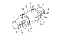
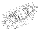
このボールスプラインは,長尺状の外周面48の対向する両側に長手方向に沿って軌道溝15(第1軌道溝)が形成された長尺状のスプライン軸1,及びスプライン軸1に嵌挿してスプライン軸1に沿って多数の転動体で成るボール7を介して摺動自在な筒状のスライダ2から構成されている。スライダ2は,それぞれの軌道溝15に対向して軌道溝16(第2軌道溝)及びそれぞれの軌道溝16に平行に伸びるリターン路49を構成するリターン路用溝17が形成された外筒となるケーシング3,ケーシング3の両端面28に取り付けられ且つ軌道溝15と軌道溝16とで形成される軌道路25とリターン路49とを連通する方向転換路20が形成されたエンドキャップ4,並びに軌道路25と一対の方向転換路20とリターン通路49とで形成される循環路50を循環転走するボール7から構成されている。ケーシング3は外周面23が円筒形に形成されている。また,エンドキャップ4は,ケーシング3の端面28側に配設されるスペーサ6とスペーサ6の外端面44に配設されるエンドキャップ本体5とから構成されている。エンドキャップ本体5は,概して内周面33と外周面34から成る円環状に形成されており,また,スペーサ6は,概して内周面41と外周面42から成る円環状に形成されている。エンドキャップ本体5には,半円弧状の外周壁21が形成され,スペーサ6には半円弧状の内周壁22が形成され,外周壁21と内周壁22とが整合して方向転換路20が形成される。
Embodiments of a ball spline according to the present invention will be described below with reference to the drawings.
The ball spline,
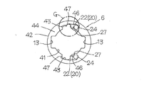
また,エンドキャップ本体5には,外周壁21の近傍に係止部となる凸部19が形成されており,スペーサ6には,内周壁22の近傍に嵌合部となる凹溝43が形成されている。即ち,エンドキャップ本体5に係止部を形成し,スペーサ6に嵌合部を形成することによって,エンドキャップ本体5の凸部19をスペーサ6の凹溝43に嵌合して,スペーサ6がエンドキャップ本体5に対して周方向に位置決め固定されて,エンドキャップ4として一体的に構成されている。エンドキャップ本体5には,外周壁21の近傍に係止部となる凸部19が形成されており,スペーサ6には,内周壁22の近傍に嵌合部となるの凹溝43が形成されており,凸部19即ち係止部が凹溝43即ち嵌合部に嵌合係止されて,スペーサ6がエンドキャップ本体5に対して周方向に位置決め固定されている。また,エンドキャップ本体5は,方向転換路20の外周壁21の領域において,膨出部39が形成され,膨出部39における凸部19に隣接して段部38が形成されている。スペーサ6は,方向転換路20の内周壁22の領域において,膨出部27における凸部46が形成されており,凸部46はエンドキャップ本体5の段部38に係合するように構成されている。また,エンドキャップ本体5の凸部19は,スペーサ6の凹溝43の一部の凹部47に係止している。スペーサ6は,エンドキャップ本体5の端面31に一方の端面44が接し且つケーシング3の端面28に他方の端面45が接している。
Further, the
この実施例では,スライダ2は,ケーシング3の一対の凹溝12が軌道溝16間に直交した位置に形成され,ケーシング3の一対のリターン路49が一方の凹溝12側に形成されている。また,一対のエンドキャップ4は,同一の構造にそれぞれ構成され,ケーシング3を挟んで両側に対向して配設されている。即ち,ケーシング3の両端面28に配設されるエンドキャップ4を構成するエンドキャップ本体5とスペーサ6は,同一の構造にそれぞれ形成されている。また,スペーサ6には,凹溝13,43が形成されている。エンドキャップ本体5の腕部10は,エンドキャップ本体5の本体部30の端面31からスペーサ6の凹溝13を通ってケーシング3の凹溝12へと延びて嵌挿されている。また,エンドキャップ本体5には,ケーシング3の軌道溝16に対向してすくい部18が形成されており,すくい部18はスペーサ6の凹溝43に位置するように配設されている。ケーシング3の軌道溝16の縁部には,軌道路25を転走するボール7を保持するため,爪部29が長手方向に形成されている。スペーサ6には,ケーシング3に形成されたリターン路用溝17に対向して貫通孔24が形成されている。スペーサ6の貫通孔24は,エンドキャップ本体5側の端面44に形成された内周壁22へと連通している。また,エンドキャップ本体5には,ケーシング3に形成された軌道溝16に対向してすくい部18が形成されており,すくい部18は軌道路25からのボール7の転走をスムーズにする。
In this embodiment, in the
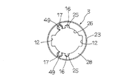
この発明によるボールスプラインは,特に,ケーシング3の円筒形の内周面26の対向位置には,エンドキャップ4を周方向に位置決めするため,長手方向の対向する全長に渡って凹溝12がそれぞれ形成されており,エンドキャップ4は,ケーシング3の凹溝12に対向する円環状の本体部30から突出してケーシング3のそれぞれの凹溝12に嵌挿する一対の腕部10が形成されており,腕部10の先端が引っ掛け鉤状部即ちフック部8に形成されて,ケーシング3の凹溝12内で対向する腕部10のフック部8同士が互いに噛み合って係合して,エンドキャップ4がケーシング3のそれぞれの端面28に周方向と軸方向に位置決めして固着されることを特徴としている。また,エンドキャップ4の腕部10は,その板厚tより大きい幅wを持つ幅広の板状部で形成され,腕部10の先端のフック部8は,腕部10の一方側から腕部10の全幅の半分以上(例えば,略2/3程度)の幅に形成された先端傾斜面40が略V字形の山形凸形状の係止突起部9と,係止突起部9に隣接して腕部10の他方側から腕部10の半分以上(例えば,略2/3程度)の幅で対向する係止突起部9と嵌合し合う相補的形状に形成された山形凹形状の嵌合凹部11とから形成されている。更に,フック部8を構成する係止突起部9は,先尖り傾斜面32と平らなガイド傾斜面53とから形成された山形凸形状の先端傾斜面40と,嵌合凹部11の先端側の壁面となって先尖り傾斜面32と同方向に傾斜する係止傾斜面35とから形成されている。具体的には,係止傾斜面35の傾斜角度θ1 は,先尖り傾斜面32の傾斜角度θ2 より大きくなっている(θ1 >θ2 )。従って,フック部8の係止突起9は,腕部10より狭くなった幅であって,しかも先尖りにテーパ状に傾斜しているので,係止突起9が嵌合凹溝11内に弾性変形して,対向する係止突起9同士が嵌合凹溝11内に嵌合し易くなり,フック部8同士が容易に互いに噛み合うようになっている。また,この実施例では,嵌合凹部11の後端側傾斜面51は,係止突起部9の先端傾斜面40に同形に形成されている。フック部8は,対向する部分が互いに弾性変形して,係止傾斜面35が互いに係合して,エンドキャップ本体5がケーシング3の端面28を押圧してエンドキャップ4がケーシング3に軸方向と周方向に位置決めして固定される。
In the ball spline according to the present invention, in particular, in order to position the
また,このボールスプラインでは,ケーシング3の一対の凹溝12は,対向する軌道溝16間を結ぶ面に対して直交した位置に形成されており,ケーシング3の一対のリターン路49は一対の軌道溝16から一方の凹溝12側へ所定位置に偏倚して形成されている。また,ケーシング3に形成されたリターン路49には,ケーシング3の内周面26に開口した開口部52が形成されており,開口部52は,ボール7の直径より小さいスリット幅で,長手方向に沿って延びており,開口部52に対向するエンドキャップ4の方向転換路20を形成する壁部分は,円環状の内周からスプライン軸1側へ突出した膨出部27,39に形成されている。更に,スプライン軸1の軌道溝15に沿って形成された凹溝14は,エンドキャップ4に形成された膨出部27,39を逃がすために形成されている。
Further, in this ball spline, the pair of
また,エンドキャップ4は,ケーシング3側に位置して方向転換路20の内周壁22を形成するスペーサ6と,スペーサ6に隣接して方向転換路20の外周壁21を形成するエンドキャップ本体5から構成されており,フック部8を備えた腕部10は,エンドキャップ本体5の中心O−O(図12)を通る平面に対して鏡像に形成されている。エンドキャップ4には,ケーシング3の凹溝12に対向する円環状の部分から突出してケーシング3のそれぞれの凹溝12内に延びて凹溝12に嵌挿する一対の腕部10が形成されている。エンドキャップ本体5の腕部10は,その両側面がケーシング3の凹溝12の壁面に嵌入する傾斜面37に形成されて固定用突起36が形成されている。このボールスプラインは,ケーシング3とエンドキャップ4とを上記のように形成することによって,スライダ2は,ケーシング3の凹溝12にエンドキャップ4の腕部10を嵌挿して対向するエンドキャップ本体5のフック部8を互いに係合させ,エンドキャップ4をケーシング3の端面28にそれぞれ固着して組み立てられる。また,ケーシング3の内周面26に形成された凹溝12は,エンドキャップ本体5に設けた腕部10の周方向両側に形成された固定用突起36を挿入できるサイズに形成されている。ケーシング3の凹溝12にエンドキャップ本体5の腕部10が嵌挿されると,固定用突起36が凹溝12の壁面に接して安定して係止状態になり,更に,腕部10に設けたフック部8が互いに噛み合って嵌合係止されるように構成されている。従って,このボールスプラインでは,従来のようにケーシング3にねじ穴を形成したり,該ねじ穴にボルトを螺入してケーシング3にエンドキャップ4を固定する必要がないものである。
The
また,エンドキャップ本体5に形成された腕部10は,エンドキャップ本体5の内周面33と同一面でスペーサ6の凹溝13とケーシング3の凹溝12に挿通できる厚みに形成されている。ケーシング3の内周面26には,エンドキャップ4の固定用突起36を挿入可能な凹溝12が形成されており,また,スペーサ6の内周面41には,エンドキャップ本体5の固定用突起36を挿入可能な凹溝13が形成されている。スペーサ6は,円環状であって,方向転換路20の位置がスプライン軸1側に突出した形状に形成されている。
The
スプライン軸1については,2条の軌道溝15が円周方向180°の位置に形成され,,軌道溝15の一方側に凹溝14がそれぞれ形成されている。それぞれの凹溝14は,エンドキャップ本体5とスペーサ6の方向転換路部20に形成された膨出部27,39を逃がす役割を果たすものである。即ち,スプライン軸1には,スペーサ6の方向転換路20の位置の突出部である膨出部39を逃がす2条の凹溝14が形成されている。また,スプライン軸1の軌道溝15は,スプライン軸1の外周面48の円周方向180°の位置に形成されており,凹溝12,13は,2条の軌道溝16で分けられた一方側のスプライン軸1の外周面48に形成されている。この実施例では,エンドキャップ本体5の方向転換路20を形成する外周壁21に設けた膨出部39と,スペーサ6の方向転換路20を形成する内周壁22に設けた膨出部27は,方向転換路20の壁部の強度を確保するために周壁を肉厚に形成するため設けられている。膨出部27,39によって,循環路50の方向転換路20は,スプライン軸1側を開口する必要がなく,ボール7は方向転換路20をスムーズに転走できるようになる。
As for the
この実施例では,スプライン軸1は,例えば,スプライン軸径がφ4mmであり,また,スライダ2は,スライダ外径即ちケーシング3の外径がφ6mmに構成され,また,スライダ2の長さが9.7mmの2条列のゴシックアーチ軌道溝タイプの極めて小形なボールスプラインに形成することができ,スライダ2を小型化することができる。また,転動体のボール7は,その直径が0.6mmに形成でき,ケーシング3の肉厚は1mmに形成することができる。ケーシング3(外筒)は金属製で,両端部にエンドキャップ4を固定する。エンドキャップ本体5とスペーサ6からなるエンドキャップ4は,合成樹脂製であって弾性変形可能に形成されている。腕部10には,エンドキャップ本体5のスペーサ6側の端面31から突き出す腕のように形成された一対の固定用突起36が形成されている。例えば,腕部10に形成した固定用突起36の幅は1.7mmであり,固定用突起36の厚みは0.4mmに形成されている。また,スライダ2を,例えば,ハウジング等の相手部材の中央孔(図示せず)に取り付ける時に,スライダ2の回転止め用として,ケーシング3の外周面23に断面形状の角度120°の皿ザグリ(図示せず)を形成してもよいものである。このような皿ざぐりは,ケーシング3の長手中央で,軌道溝16やリターン路用溝17と干渉せず,ケーシング3が変形等の悪影響を受けない任意の位置に形成してもよいものである。
In this embodiment, for example, the
ケーシング3のリターン路49は,ボール7の直径より小さい開口幅で長手方向に沿ってケーシング3の内周面26に開口した開口部52が形成されている。開口部52に対向するエンドキャップ4の方向転換路20の対向壁部分は,円環状の内周からスプライン軸1へ突出した膨出部27に形成され,リターン路49が方向転換路20へと連通している。エンドキャップ本体5とスペーサ6は,方向転換路20の壁面を肉厚にするため,スプライン軸1側に膨出した形状の膨出部27に形成されている。即ち,ケーシング3に形成されたリターン路49は,ケーシング3の内径面側がスプライン軸1側に開口部52のスリットによって開口した状態であり,ボール7がリターン路49を転走する時には,ボール7はスプライン軸1の外周面48に接触しない状態になっており,ケーシング3を可及的に薄肉に形成できるようになっている。このボールスプラインでは,金属製のケーシング3に形成される軌道溝16とリターン路49を構成するリターン路用溝17とは,例えば,ワイヤーカット放電加工で同時に加工することができる。
The
この発明によるボールスプラインは,半導体製造装置,精密機械,測定・検査装置,医療機器,各種ロボット,各種組立装置,搬送機械,工作機械,マイクロマシーン等の各種装置に組み込んで利用して好ましいものである。 The ball spline according to the present invention is preferably used by being incorporated in various devices such as semiconductor manufacturing equipment, precision machinery, measuring / inspecting equipment, medical equipment, various robots, various assembling equipment, transporting machines, machine tools, and micromachines. is there.
1 スプライン軸
2 スライダ
3 ケーシング
4 エンドキャップ
5 エンドキャップ本体
6 スペーサ
7 ボール(転動体)
8 フック部
9 係止突起部
10 腕部
11 嵌合凹部
12,13 凹溝
15 軌道溝(第1軌道溝)
16 軌道溝(第2軌道溝)
17 リターン路用溝
19 凸部(係止部)
20 方向転換路
21 外周壁
22 内周壁
25 軌道路
26 内周面
27,39 膨出部
28 端面
30 本体部
35 係止傾斜面
40 先端傾斜面
43 凹溝(嵌合部)
48 外周面
49 リターン路
50 循環路
52 開口部
O エンドキャップの中心
1
8
16 Track groove (second track groove)
17 Groove for
20
48 outer
Claims (9)
前記ケーシングの内周面の対向位置には,前記エンドキャップを周方向に位置決めするため前記長手方向の全長に渡って伸びる凹溝がそれぞれ形成されており,
前記エンドキャップは,円環状の本体部からそれぞれ突出して前記ケーシングの前記凹溝に嵌挿する一対の腕部を備えており,前記腕部の先端部にはフック部が形成され,前記ケーシングの前記凹溝内で対向する前記腕部の前記フック部同士が互いに噛み合って係合し,前記エンドキャップが前記ケーシングの前記端面に周方向と軸方向に位置決めしてそれぞれ固定されることを特徴とするボールスプライン。 A long spline shaft in which a first raceway groove is formed along the longitudinal direction on both sides of the outer peripheral surface, and is inserted into the spline shaft and relative to the spline shaft via balls as a number of rolling elements. The slider is formed of a slidable cylindrical slider, and the slider has a second raceway groove facing the first raceway groove and a casing formed in parallel with the second raceway groove. An end cap attached to both end faces and formed with a direction change path that connects the track path formed by the first track groove and the second track groove and the return path, and the track path and the pair of the above-mentioned In the ball spline consisting of the ball that circulates and circulates in the circulation path composed of the direction change path and the return path,
Concave grooves extending over the entire length in the longitudinal direction are formed at positions facing the inner peripheral surface of the casing in order to position the end cap in the circumferential direction.
The end cap includes a pair of arm portions that protrude from the annular main body portion and fit into the concave groove of the casing, and a hook portion is formed at a tip portion of the arm portion. The hook portions of the arm portions opposed to each other in the concave groove are engaged with each other, and the end cap is positioned and fixed to the end surface of the casing in the circumferential direction and the axial direction, respectively. Ball spline to do.
Priority Applications (1)
| Application Number | Priority Date | Filing Date | Title |
|---|---|---|---|
| JP2014068025A JP6334986B2 (en) | 2014-03-28 | 2014-03-28 | Ball spline |
Applications Claiming Priority (1)
| Application Number | Priority Date | Filing Date | Title |
|---|---|---|---|
| JP2014068025A JP6334986B2 (en) | 2014-03-28 | 2014-03-28 | Ball spline |
Publications (3)
| Publication Number | Publication Date |
|---|---|
| JP2015190560A JP2015190560A (en) | 2015-11-02 |
| JP2015190560A5 JP2015190560A5 (en) | 2017-04-13 |
| JP6334986B2 true JP6334986B2 (en) | 2018-05-30 |
Family
ID=54425219
Family Applications (1)
| Application Number | Title | Priority Date | Filing Date |
|---|---|---|---|
| JP2014068025A Active JP6334986B2 (en) | 2014-03-28 | 2014-03-28 | Ball spline |
Country Status (1)
| Country | Link |
|---|---|
| JP (1) | JP6334986B2 (en) |
Families Citing this family (9)
| Publication number | Priority date | Publication date | Assignee | Title |
|---|---|---|---|---|
| US11635782B2 (en) | 2017-02-17 | 2023-04-25 | Lg Electronics Inc. | Knob assembly for cook top |
| KR101913927B1 (en) | 2017-02-17 | 2018-10-31 | 엘지전자 주식회사 | Knob assembly for cook top |
| US10732666B2 (en) | 2017-02-17 | 2020-08-04 | Lg Electronics Inc. | Knob assembly for cook top |
| EP3783264B1 (en) * | 2017-02-17 | 2024-04-03 | LG Electronics Inc. | Cooking apparatus having knob assembly |
| KR102174849B1 (en) | 2017-07-26 | 2020-11-05 | 엘지전자 주식회사 | Universal joint and knob assembly and appliance therewith |
| KR102101415B1 (en) | 2017-07-24 | 2020-04-16 | 엘지전자 주식회사 | Knob assembly and appliance therewith |
| KR101912932B1 (en) | 2017-02-22 | 2018-10-29 | 엘지전자 주식회사 | Knob assembly having display device for cook top |
| KR102103016B1 (en) | 2017-02-17 | 2020-04-21 | 엘지전자 주식회사 | Knob assembly for cook top |
| JP2023127821A (en) * | 2022-03-02 | 2023-09-14 | 日本トムソン株式会社 | Linear motion guide unit |
Family Cites Families (3)
| Publication number | Priority date | Publication date | Assignee | Title |
|---|---|---|---|---|
| JPS5928773B2 (en) * | 1982-02-12 | 1984-07-16 | 博 寺町 | Ball spline bearing for infinite sliding |
| JP2002364645A (en) * | 2001-06-11 | 2002-12-18 | Nsk Ltd | Linear guide bearing device |
| JP2010242950A (en) * | 2009-04-10 | 2010-10-28 | Jtekt Corp | Ball spline |
-
2014
- 2014-03-28 JP JP2014068025A patent/JP6334986B2/en active Active
Also Published As
| Publication number | Publication date |
|---|---|
| JP2015190560A (en) | 2015-11-02 |
Similar Documents
| Publication | Publication Date | Title |
|---|---|---|
| JP6334986B2 (en) | Ball spline | |
| JP4965362B2 (en) | Roller type linear motion guide unit | |
| JP6475533B2 (en) | Linear motion guidance unit | |
| JP2015190560A5 (en) | ||
| JP2021188687A (en) | Ball screw device | |
| JP2006220215A (en) | Piece-type ball screw | |
| US10221543B2 (en) | Attachment pin assembly | |
| JP6122636B2 (en) | Linear motion guide unit with plug on track rail | |
| JP6383553B2 (en) | Ball spline | |
| JP4916873B2 (en) | Ball screw / ball nut mechanism | |
| JP2009281534A (en) | Ball screw device | |
| JP2006234032A (en) | Linear guide bearing device | |
| JP6349084B2 (en) | Ball spline | |
| JP2016169819A (en) | Attachment component of return tube and ball screw | |
| JP6294664B2 (en) | Ball spline | |
| WO2019130385A1 (en) | Ball screw | |
| JP2007155036A (en) | Linear bush, and its manufacturing method | |
| CN113260805B (en) | Ball screw device | |
| JP4717758B2 (en) | Exercise guidance device | |
| JP2014119036A (en) | Installation structure of linear guide device | |
| TWI717681B (en) | Rolling body screw device | |
| JP2019065882A (en) | Needle roller with cage | |
| TWM606371U (en) | Dustproof element and ball screw rod using dustproof element | |
| JP2006183821A (en) | Sliding device | |
| JP2007271041A (en) | Linear motion guide |
Legal Events
| Date | Code | Title | Description |
|---|---|---|---|
| A521 | Written amendment |
Free format text: JAPANESE INTERMEDIATE CODE: A523 Effective date: 20170308 |
|
| A621 | Written request for application examination |
Free format text: JAPANESE INTERMEDIATE CODE: A621 Effective date: 20170308 |
|
| A977 | Report on retrieval |
Free format text: JAPANESE INTERMEDIATE CODE: A971007 Effective date: 20171211 |
|
| A131 | Notification of reasons for refusal |
Free format text: JAPANESE INTERMEDIATE CODE: A131 Effective date: 20180123 |
|
| A521 | Written amendment |
Free format text: JAPANESE INTERMEDIATE CODE: A523 Effective date: 20180216 |
|
| TRDD | Decision of grant or rejection written | ||
| A01 | Written decision to grant a patent or to grant a registration (utility model) |
Free format text: JAPANESE INTERMEDIATE CODE: A01 Effective date: 20180424 |
|
| A61 | First payment of annual fees (during grant procedure) |
Free format text: JAPANESE INTERMEDIATE CODE: A61 Effective date: 20180427 |
|
| R150 | Certificate of patent or registration of utility model |
Ref document number: 6334986 Country of ref document: JP Free format text: JAPANESE INTERMEDIATE CODE: R150 |
|
| R250 | Receipt of annual fees |
Free format text: JAPANESE INTERMEDIATE CODE: R250 |


