JP6334177B2 - Operation plan creation device, control device, operation plan creation method, and program - Google Patents
Operation plan creation device, control device, operation plan creation method, and program Download PDFInfo
- Publication number
- JP6334177B2 JP6334177B2 JP2014006158A JP2014006158A JP6334177B2 JP 6334177 B2 JP6334177 B2 JP 6334177B2 JP 2014006158 A JP2014006158 A JP 2014006158A JP 2014006158 A JP2014006158 A JP 2014006158A JP 6334177 B2 JP6334177 B2 JP 6334177B2
- Authority
- JP
- Japan
- Prior art keywords
- energy
- operation plan
- unit
- plan creation
- consumption
- Prior art date
- Legal status (The legal status is an assumption and is not a legal conclusion. Google has not performed a legal analysis and makes no representation as to the accuracy of the status listed.)
- Active
Links
Images


Classifications
-
- G—PHYSICS
- G05—CONTROLLING; REGULATING
- G05F—SYSTEMS FOR REGULATING ELECTRIC OR MAGNETIC VARIABLES
- G05F1/00—Automatic systems in which deviations of an electric quantity from one or more predetermined values are detected at the output of the system and fed back to a device within the system to restore the detected quantity to its predetermined value or values, i.e. retroactive systems
- G05F1/66—Regulating electric power
-
- G—PHYSICS
- G05—CONTROLLING; REGULATING
- G05B—CONTROL OR REGULATING SYSTEMS IN GENERAL; FUNCTIONAL ELEMENTS OF SUCH SYSTEMS; MONITORING OR TESTING ARRANGEMENTS FOR SUCH SYSTEMS OR ELEMENTS
- G05B11/00—Automatic controllers
- G05B11/01—Automatic controllers electric
-
- G—PHYSICS
- G05—CONTROLLING; REGULATING
- G05B—CONTROL OR REGULATING SYSTEMS IN GENERAL; FUNCTIONAL ELEMENTS OF SUCH SYSTEMS; MONITORING OR TESTING ARRANGEMENTS FOR SUCH SYSTEMS OR ELEMENTS
- G05B13/00—Adaptive control systems, i.e. systems automatically adjusting themselves to have a performance which is optimum according to some preassigned criterion
- G05B13/02—Adaptive control systems, i.e. systems automatically adjusting themselves to have a performance which is optimum according to some preassigned criterion electric
- G05B13/0205—Adaptive control systems, i.e. systems automatically adjusting themselves to have a performance which is optimum according to some preassigned criterion electric not using a model or a simulator of the controlled system
- G05B13/021—Adaptive control systems, i.e. systems automatically adjusting themselves to have a performance which is optimum according to some preassigned criterion electric not using a model or a simulator of the controlled system in which a variable is automatically adjusted to optimise the performance
-
- G—PHYSICS
- G06—COMPUTING; CALCULATING OR COUNTING
- G06Q—INFORMATION AND COMMUNICATION TECHNOLOGY [ICT] SPECIALLY ADAPTED FOR ADMINISTRATIVE, COMMERCIAL, FINANCIAL, MANAGERIAL OR SUPERVISORY PURPOSES; SYSTEMS OR METHODS SPECIALLY ADAPTED FOR ADMINISTRATIVE, COMMERCIAL, FINANCIAL, MANAGERIAL OR SUPERVISORY PURPOSES, NOT OTHERWISE PROVIDED FOR
- G06Q10/00—Administration; Management
- G06Q10/06—Resources, workflows, human or project management; Enterprise or organisation planning; Enterprise or organisation modelling
-
- G—PHYSICS
- G06—COMPUTING; CALCULATING OR COUNTING
- G06Q—INFORMATION AND COMMUNICATION TECHNOLOGY [ICT] SPECIALLY ADAPTED FOR ADMINISTRATIVE, COMMERCIAL, FINANCIAL, MANAGERIAL OR SUPERVISORY PURPOSES; SYSTEMS OR METHODS SPECIALLY ADAPTED FOR ADMINISTRATIVE, COMMERCIAL, FINANCIAL, MANAGERIAL OR SUPERVISORY PURPOSES, NOT OTHERWISE PROVIDED FOR
- G06Q50/00—Systems or methods specially adapted for specific business sectors, e.g. utilities or tourism
- G06Q50/06—Electricity, gas or water supply
-
- G—PHYSICS
- G05—CONTROLLING; REGULATING
- G05B—CONTROL OR REGULATING SYSTEMS IN GENERAL; FUNCTIONAL ELEMENTS OF SUCH SYSTEMS; MONITORING OR TESTING ARRANGEMENTS FOR SUCH SYSTEMS OR ELEMENTS
- G05B2219/00—Program-control systems
- G05B2219/30—Nc systems
- G05B2219/49—Nc machine tool, till multiple
- G05B2219/49068—Minimum cost adaptive
Description
本発明の実施形態は、運転計画作成装置、制御装置、運転計画作成方法、およびプログラムに関する。 Embodiments described herein relate generally to an operation plan creation device, a control device, an operation plan creation method, and a program.
近年、環境への配慮から、建築物のゼロ・エネルギー・ビル(ZEB)化が推進されている。経済産業省の定義によると、ZEBとは、「建築物における一次エネルギー消費量を、建築物・設備の省エネ性能の向上、エネルギーの面的利用、オンサイトでの再生可能エネルギーの活用等により削減し、年間での一次エネルギー消費量が正味(ネット)でゼロ又は概ねゼロとなる建築物」である。また、実際の建築物においては、一次エネルギー消費量に加え、エネルギーコストも考慮されることが望ましい。 In recent years, building a zero energy building (ZEB) has been promoted in consideration of the environment. According to the Ministry of Economy, Trade and Industry's definition, ZEB is “reducing primary energy consumption in buildings by improving the energy-saving performance of buildings and equipment, using energy more and using renewable energy on-site. And the building where the annual primary energy consumption is zero or almost zero on the net (net). In an actual building, it is desirable to consider energy cost in addition to primary energy consumption.
本発明が解決しようとする課題は、エネルギー供給装置の一次エネルギー消費量を小さくしつつ、エネルギーコストを小さくすることができる運転計画作成装置、制御装置、運転計画作成方法、およびプログラムを提供することである。 The problem to be solved by the present invention is to provide an operation plan creation device, a control device, an operation plan creation method, and a program capable of reducing the energy cost while reducing the primary energy consumption of the energy supply device. It is.
実施形態の運転計画作成装置は、消費量算出部と、コスト算出部と、運転計画作成部と、を持つ。消費量算出部は、負荷に対してエネルギーを供給する複数のエネルギー供給装置による一次エネルギー消費量を算出する。コスト算出部は、前記複数のエネルギー供給装置がエネルギーの生成に要するエネルギーコストを算出する。運転計画作成部は、前記消費量算出部が算出する前記一次エネルギー消費量と前記コスト算出部が算出する前記エネルギーコストとに基づいて、前記一次エネルギー消費量がゼロまたは負の値となることである前記一次エネルギー消費量に対する目標を達成した上で、前記エネルギーコストを最小化する前記エネルギーコストに対する目標を夫々達成するように、前記複数のエネルギー供給装置の運転計画を作成する。 The operation plan creation apparatus according to the embodiment includes a consumption calculation unit, a cost calculation unit, and an operation plan creation unit. The consumption calculation unit calculates primary energy consumption by a plurality of energy supply devices that supply energy to the load. The cost calculation unit calculates an energy cost required for generating energy by the plurality of energy supply devices. The operation plan creation unit is configured such that the primary energy consumption becomes zero or a negative value based on the primary energy consumption calculated by the consumption calculation unit and the energy cost calculated by the cost calculation unit. After achieving a target for the primary energy consumption, an operation plan for the plurality of energy supply apparatuses is created so as to achieve the target for the energy cost that minimizes the energy cost .
以下、実施形態の運転計画作成装置および制御装置を図面を参照して説明する。
(第1の実施形態)
まず、第1の実施形態の運転計画作成装置とその周辺装置との接続の態様の一例について説明する。
図1は、第1の実施形態の運転計画作成装置とその周辺装置の全体構成の一例を示す図である。
Hereinafter, an operation plan creation device and a control device according to an embodiment will be described with reference to the drawings.
(First embodiment)
First, an example of a connection mode between the operation plan creation device of the first embodiment and its peripheral devices will be described.
FIG. 1 is a diagram illustrating an example of the overall configuration of an operation plan creation device and its peripheral devices according to the first embodiment.
第1の実施形態に係る運転計画作成装置1は、ビルや住宅などの建物2の負荷に対して電力、冷熱、温熱などのエネルギーを供給するエネルギー供給プラント3の運転計画を作成する装置である。ここで、建物は、エネルギーを受容する建築物、建造物、施設、および設備などを含む。また、本明細書において、エネルギー供給プラント3は、複数のエネルギー供給装置を備え、当該複数のエネルギー供給装置全体を指して、エネルギー供給プラント3と称することがある。例えば、エネルギー供給プラント3の運転計画とは、エネルギー供給プラント3が備えるエネルギー供給装置の運転計画を示す。
The operation
また、運転計画作成装置1は、一次エネルギー消費量とエネルギーコストとに基づいて運転計画を作成する。一次エネルギーとは、石炭、石油、天然ガス、薪、水力、原子力、風力、潮流、地熱、太陽エネルギーなど自然から直接採取されるエネルギーのことである。本明細書において、一次エネルギーの消費量は、電力、ガス、およびバイオマス燃料の消費量に一次エネルギー換算値を乗じて算出される。なお、太陽光発電やバイオマスコジェネ等のいわゆる再生可能エネルギーによる創エネルギー量は、一次エネルギー消費量から削減して考えるものとする。
The operation
運転計画作成装置1とエネルギー供給プラント3とは、内部ネットワーク4により接続されている。内部ネットワーク4は、さらに制御装置5と、外部通信サーバ6と、が接続され、運転計画作成装置1、エネルギー供給プラント3、制御装置5、および外部通信サーバ6は、互いに通信を行うことができる。
The operation
制御装置5は、運転計画作成装置1が作成する運転計画に基づいて、エネルギー供給プラント3が備えるエネルギー供給装置を制御する。具体的には、制御装置5は、運転計画作成装置1から受信したエネルギー供給装置の起動、出力レベルなどの作動状態、および停止などを示す制御設定値に基づいて、エネルギー供給装置を制御する。また、制御装置5は、エネルギー供給プラント3の運用データを保存するとともに、エネルギー供給プラント3が正常に動作しているか否かなどの運転状態を監視する。制御装置5は、時々刻々と変化する建物2のエネルギー需要に応じたエネルギー量を供給できるように、運転計画に基づいて、エネルギー供給プラント3を制御する。制御装置5は、例えば、公知のサーバ機能を備えるサーバ装置であり、装置の内部にCPU(Central Processing Unit)や記憶装置を備える。
The
外部通信サーバ6は、外部ネットワーク7と接続されている。外部通信サーバ6は、外部ネットワーク7を介して、気象情報サーバ8と通信を行う。気象情報サーバ8は、過去の気象についての気象データとみらいの気象についての気象予測データとを有している。外部通信サーバ6は、気象情報サーバ8から過去の気象データおよび未来の気象予測データを取得する。外部ネットワーク7は、内部ネットワーク4を介して、取得した気象データを運転計画作成装置1に送信する。
The
内部ネットワーク4および外部ネットワーク7は、例えば、携帯電話網、PHS(Personal Handy-phone System)網、VPN(Virtual Private Network)網、専用通信回線網、WAN(Wide Area Network)、LAN(Local Area Network)、PSTN(Public Switched Telephone Network;公衆交換電話網)などによって構成される情報通信ネットワークであり、また、これらの組み合わせであってもよい。
The
次に、エネルギー供給プラント3が備える各種エネルギー供給装置からのエネルギーの流れの一例について説明する。建物2は、電力、温熱、および冷熱のエネルギーを受容する。図1において、建物2による電力、温熱、および冷熱のエネルギー需要は、それぞれ電力負荷21、温熱負荷22、および冷熱負荷23として示されている。温熱や冷熱のエネルギーは、例えば、水を媒体として供給される。
Next, an example of the flow of energy from various energy supply devices provided in the
エネルギー供給プラント3は、受電設備311と、PV(PhotoVoltaics、太陽光発電設備)312と、蓄電池313と、CGS(Co-Generation System、コジェネ)321と、ボイラ322と、温熱槽323と、空冷冷凍機331と、水冷冷凍機332と、冷熱槽333と、吸収式冷凍機334と、を備える。
The
受電設備311は、電力会社から電力を受電し、施設に適した電圧に変換する。
PV312は、太陽光のエネルギーを電気エネルギーに変換する太陽光パネルを備えた発電設備である。PV312が供給する電気エネルギーの量は、天候などの気象条件により変化する。
蓄電池313は、充電および放電の双方を行うことが可能な二次電池を利用した設備である。
The
The PV 312 is a power generation facility provided with a solar panel that converts sunlight energy into electrical energy. The amount of electrical energy supplied by the
The
CGS321は、内燃機関や外燃機関によって発電を行うとともに、その排熱を温熱として利用可能なシステムである。本実施形態においてCGS321は、バイオマス燃料をエネルギー源とするが、例えば、ガスをエネルギー源として用いてもよい。
ボイラ322は、ガスをエネルギー源として温熱を供給する。
温熱槽323は、貯留した熱媒により蓄熱を行う。温熱槽323は、例えば、水蓄熱槽である。
The CGS 321 is a system capable of generating electric power with an internal combustion engine or an external combustion engine and using the exhaust heat as heat. In the present embodiment, the CGS 321 uses biomass fuel as an energy source, but may use gas as an energy source, for example.
The
The
空冷冷凍機331は、空気を熱源として冷媒の相変化により冷水を供給する機器である。
水冷冷凍機332は、水を熱源として冷媒の相変化により冷水を供給する機器である。
冷熱槽333は、貯留した熱媒により蓄熱を行う。冷熱槽333は、例えば、水蓄熱槽や氷蓄熱槽である。
吸収式冷凍機334は、冷媒の凝縮器と蒸発器との間に、水蒸気の吸収と熱源による再生プロセスとを介在させて、冷水を供給する機器である。
The air-cooled
The water-cooled
The
The
上述したように、エネルギー供給装置のうち、空冷冷凍機331、水冷冷凍機332、冷熱槽333、および吸収式冷凍機334が冷熱の供給を行う冷熱供給装置である。このうち、空冷冷凍機331および水冷冷凍機332は、冷熱の生成に電力を要するため、受電設備311、PV312、および蓄電池313は、建物2に加え、空冷冷凍機331および水冷冷凍機332に電力を供給する。また、吸収式冷凍機334は、冷熱の生成に温熱を要するため、CGS321、ボイラ322、および温熱槽323は、建物2に加え、吸収式冷凍機334に温熱を供給する。CGS321およびボイラ322は、温熱を生成する温熱供給装置である。また、CGS321は、電力を供給する電力供給装置でもある。
As described above, among the energy supply devices, the air-cooled
蓄電池313、温熱槽323、および冷熱槽333は、エネルギーを貯蔵することができる。蓄電池313は、PV312およびCGS321により生成された電力を、例えば、電力の生成に要するエネルギーコストが低いときに蓄え、当該エネルギーコストが高いときに電力負荷21に供給する。また、温熱槽323は、CGS321およびボイラ322により生成された温熱を、例えば、温熱の生成に要するエネルギーコストが低いときに蓄え、当該エネルギーコストが高いときに温熱負荷22に供給する。同様に、冷熱槽333は、空冷冷凍機331、水冷冷凍機332、および吸収式冷凍機334により生成された冷熱を、例えば、冷熱の生成に要するエネルギーコストが低いときに蓄え、当該エネルギーコストが高いときに冷熱負荷23に供給する。
The
次に、運転計画作成装置1の構成について説明する。
図2は、運転計画作成装置1の全体構成の一例を示す図である。
運転計画作成装置1は、例えば、公知のサーバ機能を備えるサーバ装置であり、装置の内部にCPUや記憶装置を備える。運転計画作成装置1が備える記憶装置は、例えば、HDD(Hard Disc Drive)、フラッシュメモリ、EEPROM(Electrically Erasable Programmable Read Only Memory)、ROM(Read Only Memory)、またはRAM(Random Access Memory)などを備え、ファームウェアやアプリケーションプログラムなど、CPUが実行するための各種プログラムやCPUが実行した処理の結果などを記憶する。
Next, the configuration of the operation
FIG. 2 is a diagram illustrating an example of the overall configuration of the operation
The operation
運転計画作成装置1は、通信部10と、モデル入力部11と、表示部12と、プロセスデータ記憶部13と、気象データ記憶部14と、プラントモデル記憶部15と、演算結果記憶部16と、演算処理部17と、プロセスデータ取得部101と、気象データ取得部102と、運転計画送信制御部103と、モデル入力制御部111と、表示制御部121と、を備える。
The operation
通信部10は、内部ネットワーク4と接続され、制御装置5および外部通信サーバ6と通信を行う。
モデル入力部11は、エネルギー供給プラント3が備えるエネルギー供給装置のプラントモデルとモデルパラメータとの入力を受け付ける。プラントモデルとモデルパラメータについては後述する。モデル入力部11は、例えば、タッチパネルやマウス、キーボードなどの入力装置を備える。また、モデル入力部11は、プラントモデルデータとモデルパラメータデータとを記憶する外部記憶装置と接続し、当該データを取得するための通信用インターフェースを備えてもよい。
表示部12は、運転計画作成装置1が作成した運転計画を表示する。表示部12は、例えば、液晶ディスプレイや有機EL(Electro-Luminescence)ディスプレイなどの表示装置を備える。
The
The
The
プロセスデータ記憶部13は、プロセスデータ131を記憶する。プロセスデータ131は、エネルギー供給プラント3の運用記録、建物2のエネルギー需要の記録などの情報を含む。これらの情報は、日時と対応付けられて記憶され、その時間間隔は、例えば、1時間単位である。
The process
気象データ記憶部14は、気象データ141を記憶する。気象データ141は、天候や日照量、日照時間、気温、湿度など、建物2のエネルギー需要、またはエネルギー供給プラント3のエネルギー生成に係る気象情報を含む。これらの情報は日時と対応付けられて記憶され、その時間間隔は、例えば、1時間単位である。また、気象データ141は、過去の気象情報の記録の他、天気予報などの気象予測情報を含む。
The weather
プラントモデル記憶部15は、プラントモデルデータ151と、モデルパラメータデータ152と、を記憶する。
プラントモデルデータ151は、エネルギー供給プラント3の態様を示すデータである。プラントモデルデータ151は、例えば、エネルギー供給プラント3が備えるエネルギー供給装置の種類とその接続態様とを示す。
The plant
The
モデルパラメータデータ152は、エネルギー供給プラント3が備えるエネルギー供給装置の詳細を示すデータである。モデルパラメータデータ152は、例えば、各エネルギー供給装置が供給するエネルギーの最大出力や、各エネルギー供給装置の入力エネルギーに対する出力エネルギーの変換効率などのデータを含む。また、モデルパラメータデータ152は、気象条件によってエネルギー生成効率の変化するPV312などについて、気象条件に応じたエネルギー出力を示すデータを含む。また、モデルパラメータデータ152は、蓄電池313、温熱槽323、冷熱槽333が蓄積可能なエネルギー量のデータを含む。また、モデルパラメータデータ152は、受電設備311が受電する電力、CGS321が消費するバイオマス燃料、およびボイラ322が消費するガスのエネルギー単価の日時毎のデータを含む。また、プラントモデルデータ151は、電力、ガス、およびバイオマス燃料の一次エネルギー換算係数などのデータを含む。
The
演算結果記憶部16は、演算処理部17による演算処理の結果を記憶し、年間計画データ161と、日間計画データ162と、ZEB化乗数データ163と、を記憶する。
年間計画データ161は、エネルギー供給プラント3が備えるエネルギー供給装置の年間の運転計画を示す。
The calculation
The
日間計画データ162は、エネルギー供給プラント3が備えるエネルギー供給装置の1日間の運転計画を示す。日間計画データ162は、例えば、エネルギー供給装置の起動、停止、および運転時の出力レベルなどを示す制御設定値を1時間単位で示す。
ZEB化乗数データ163は、ZEB化乗数の設定値を示す。ZEB化乗数の詳細については後述する。
The daily plan data 162 indicates a one-day operation plan of the energy supply device provided in the
The
プロセスデータ取得部101、気象データ取得部102、運転計画送信制御部103、モデル入力制御部111、表示制御部121、および演算処理部17は、例えば、運転計画作成装置1が記憶装置に記憶するプログラムを、CPUが実行することによって機能する。
For example, the operation
プロセスデータ取得部101は、通信部10を介して、制御装置5からエネルギー供給プラント3のプロセスデータを取得する。ここで、プロセスデータ取得部101は、エネルギー供給プラント3から直接プロセスデータを取得してもよい。プロセスデータ取得部101は、取得したプロセスデータをプロセスデータ記憶部13に記憶させる。
気象データ取得部102は、通信部10を介して外部通信サーバ6と通信を行い、外部通信サーバ6が気象情報サーバ8から取得した気象データおよび気象予測データを取得する。気象データ取得部102は、取得した気象データおよび気象予測データを気象データ記憶部14に記憶させる。
The process
The meteorological
運転計画送信制御部103は、演算結果記憶部16から日間計画データ162を読み出し、読み出したデータを通信部10を介して制御装置5に送信する。
モデル入力制御部111は、モデル入力部11が受け付けたプラントモデルデータおよびモデルパラメータデータを、それぞれ、プラントモデルデータ151およびモデルパラメータデータ152としてプラントモデル記憶部15に記憶させる。
The operation plan
The model
表示制御部121は、演算結果記憶部16から年間計画データ161および日間計画データ162を読み出し、表示部12にエネルギー供給プラント3の運転計画を表示させる。表示制御部121は、例えば、エネルギー供給プラント3が備えるエネルギー供給装置の時刻毎の運転状態を表形式、グラフ形式など様々な表示態様で表示させてよい。
The
演算処理部17は、建物2によるエネルギー需要の予測を行い、当該予測した需要量に応じたエネルギー量を供給するためのエネルギー供給プラント3の運転計画を作成する。演算処理部17は、需要予測部18と、運転計画作成部19と、を備える。
需要予測部18は、プロセスデータ131と気象データ141とに基づいて、建物2によるエネルギーの需要量の予測を行う。需要予測部18は、年間需要予測部181と、日間需要予測部182と、を備える。
The
The
年間需要予測部181は、建物2による1年間のエネルギー需要の時間変化を予測する。年間需要予測部181は、プロセスデータ記憶部13からプロセスデータ131を取得する。また、年間需要予測部181は、気象データ記憶部14から気象データ141を取得する。年間需要予測部181は、取得したプロセスデータと取得した気象データ141とに基づいて、1年間のエネルギー需要の時間変化を予測する。
The annual
年間需要予測部181は、例えば、過去数年間のエネルギー需要の平均値を時刻毎に算出し、1年間の平均的な1日のエネルギー需要の時間変化を算出する。このように算出した1日間におけるエネルギー需要の時間変化が365日続くと考えることで、1年間のエネルギー需要の時間変化が予測されうる。
The annual
また、年間需要予測部181は、例えば、過去1年間について、月間のエネルギー需要の平均値を時刻毎に算出し、1か月間の平均的な1日のエネルギー需要の時間変化を算出する。そして、この計算を各月について行い、年間需要予測部181は、12の月各々の平均的な1日について、エネルギー需要の時間変化を算出してもよい。このように算出した1日間のエネルギー需要の時間変化が各月毎に続くと考えることで、1年間のエネルギー需要の時間変化が予測されうる。年間需要予測部181は、予測した1年間のエネルギー需要の時間変化を示す年間需要予測データを運転計画作成部19に出力する。
For example, for the past year, the annual
日間需要予測部182は、建物2による1日間のエネルギー需要の時間変化を予測する。日間需要予測部182は、プロセスデータ記憶部13からプロセスデータ131を取得する。また、日間需要予測部182は、気象データ記憶部14から気象データ141を取得する。日間需要予測部182は、取得したプロセスデータ131と取得した気象データ141とに基づいて、1日間のエネルギー需要の時間変化を予測する。日間需要予測部182は、例えば、エネルギー需要を予測する1日間の気象予報に基づいて、気温とエネルギー需要の回帰モデルなどにより、1日間のエネルギー需要の時間変化を予測する。日間需要予測部182は、予測した1日間のエネルギー需要の時間変化を示す日間需要予測データを運転計画作成部19に出力する。
The daily
運転計画作成部19は、年間運転計画作成部191は、年間需要予測部181から取得した年間需要予測データと、プラントモデル記憶部15から取得したプラントモデルデータ151と、モデルパラメータデータ152とに基づいて、エネルギー供給プラント3の1年間の運転計画を作成する。以下に、運転計画作成部19による運転計画の作成方法の原理に係る数式について説明する。
The operation

ここで、変数dは日にちを示す。変数tは、1日を0時から23時で示した場合の時刻を示す。pe(t)は、時刻tにおける電力の単価[円/kWh]を示す。pgおよびpoは、それぞれ、ガスおよびバイオマス燃料の単価[円/kWh]を示す。eu(t)は、時刻tにおける受電設備311の受電電力量[kWh]示す。gu(t)は、時刻tにおけるボイラ322のガス消費量[kWh]。ou(t)は、時刻tにおけるCGS321の燃料消費量[kWh]を示す。すなわち、上記の式(1)の左辺は1年間の総エネルギーコストを示している。従って、上記の式(1)の解は、エネルギーコストを最小化する。
Here, the variable d indicates the date. The variable t indicates the time when the day is indicated from 0:00 to 23:00. p e (t) represents the unit price [yen / kWh] of power at time t. p g and p o, respectively, indicating the price of gas and biomass fuels Circle / kWh]. e u (t) indicates the amount of received power [kWh] of the
ここで、αe、αg、およびαoは、それぞれ電力、ガス、およびバイオマス燃料の1次エネルギー換算係数を示す。また、ed(t)は、時刻tにおける建物2による需要電力量[kWh]を示す。また、eR(t)は、時刻tにおける空冷冷凍機331および水冷冷凍機332の消費電力量の合計[kWh]を示す。また、eCGS(t)およびePV(t)は、それぞれ、時刻tにおけるCGS321およびPV312による発電電力量[kWh]を示す。
Here, α e , α g , and α o indicate primary energy conversion factors of electric power, gas, and biomass fuel, respectively. Moreover, e d (t) indicates the amount of power demand [kWh] by the
すなわち、上記の式(2)の左辺は、消費したエネルギーの一次エネルギー換算量を示し、右辺は、生成した再生可能エネルギーの一次エネルギー換算量を示す。従って、式(2)は、ZEBを達成するための条件を示している。
その他、目的関数式(1)の制約条件として、以下の式(3)〜(20)がある。
That is, the left side of the above equation (2) indicates the primary energy conversion amount of the consumed energy, and the right side indicates the primary energy conversion amount of the generated renewable energy. Therefore, Formula (2) shows the conditions for achieving ZEB.
In addition, there are the following formulas (3) to (20) as constraints of the objective function formula (1).
ここで、eST(t)は、時刻tにおける蓄電池313の放電電力量[kWh]を示す。また、eST(t)が負の値の場合には、eST(t)は、蓄電池313に充電される蓄電電力量[kWh]を示す。従って、式(3)は、電力の需要と供給とのバランスを示す。
Here, e ST (t) represents the amount of discharge power [kWh] of the
ここで、cR(t)は、時刻tにおける空冷冷凍機331および水冷冷凍機332の出力熱量の合計[kWh]を示す。cABR(t)およびcST(t)は、それぞれ、時刻tにおける吸収式冷凍機334および冷熱槽333の出力熱量[kWh]を示す。また、cd(t)は、時刻tにおける建物2による冷熱需要量[kWh]を示す。また、cST(t)が負の値の場合には、cST(t)は、冷熱槽333に貯蔵される冷熱量[kWh]を示す。従って、式(4)は、冷熱の需要と供給とのバランスを示す。
Here, c R (t) represents the total output power [kWh] of the air-cooled
ここで、hCGS(t)、hB(t)、およびhST(t)は、それぞれ、時刻tにおけるCGS321、ボイラ322、および温熱槽323の出力熱量[kWh]を示す。hABR(t)は、時刻tにおける吸収式冷凍機334の入力熱量[kWh]を示す。hd(t)は、時刻tにおける建物2による温熱需要量[kWh]を示す。また、hST(t)が負の値の場合には、hST(t)は、温熱槽323に貯蔵される温熱量[kWh]を示す。従って、式(5)は、温熱の需要と供給とのバランスを示す。
Here, h CGS (t), h B (t), and h ST (t) indicate output calories [kWh] of the
ここで、WST(t)は、時刻tにおける蓄電池313の蓄電量[kWh]を示す。
Here, W ST (t) indicates the amount [kWh] of power stored in the
ここで、Qc(t)は、時刻tにおける冷熱槽333の蓄熱量[kWh]を示す。
Here, Q c (t) indicates the amount of heat stored [kWh] in the
ここで、Qh(t)は、時刻tにおける温熱槽323の蓄熱量[kWh]を示す。
Here, Q h (t) indicates the heat storage amount [kWh] of the
式(9)〜(13)において、fは関数を示し、式(9)から(13)は、それぞれ、hCGS(t)、eCGS(t)、hB(t)、CR(t)、CABR(t)の算出式を示す。 In Expressions (9) to (13), f represents a function, and Expressions (9) to (13) represent h CGS (t), e CGS (t), h B (t), and C R (t, respectively. ) And C ABR (t) are calculated.
式(14)〜(16)は、それぞれ、蓄電池313による蓄電、冷熱槽333による蓄熱、温熱槽323による蓄熱の容量についての制約を示す。
Expressions (14) to (16) indicate restrictions on the capacities of power storage by the
式(17)および式(18)は、それぞれ、CGS321の出力熱量および出力電力についての制約を示す。
Equations (17) and (18) show constraints on the output heat amount and output power of the
式(19)は、空冷冷凍機331および水冷冷凍機332による出力熱量の合計についての制約を示す。
Expression (19) shows a restriction on the total amount of output heat by the air-cooled
式(20)は、吸収式冷凍機334による出力熱量についての制約を示す。
建物2のZEB化を達成しつつ、エネルギーコストを最小化するには、上述の式(2)〜(20)に示す制約条件の下で式(1)の最適解を取得すればよい。以下ではこの問題を、年間運転計画問題と称することがある。制約条件式(2)〜(20)のうち、式(3)〜(20)は、各時刻における制約条件、または、前後の時刻間にまたがる制約条件であるため、時間経過に従って順に解くことにより、1日毎の制約条件として扱うことが可能である。
Expression (20) shows a restriction on the amount of heat output by the
In order to minimize the energy cost while achieving the ZEB conversion of the
これに対し、制約条件式(2)は、1年間にまたがる制約条件であり、これをそのまま解こうとすると、計算量が膨大になる。そこで、制約条件式(2)をラグランジュ緩和し、目的関数式(1)に組み込むことで、以下の式(21)が得られる。 On the other hand, the constraint condition expression (2) is a constraint condition that extends over one year, and if this is solved as it is, the amount of calculation becomes enormous. Therefore, the following equation (21) is obtained by relaxing the Lagrangian constraint equation (2) and incorporating it into the objective function equation (1).
ここでγは、ラグランジュ乗数を示し、ゼロより大きい値である。また、ラグランジュ乗数γは、ZEBの達成条件の重みを示し、以下ではγをZEB化乗数と称する。式(20)を式(3)に基づいて整理すると、以下の式(22)が得られる。 Here, γ represents a Lagrange multiplier and is a value larger than zero. The Lagrange multiplier γ indicates the weight of the ZEB achievement condition, and γ is hereinafter referred to as a ZEB multiplier. When formula (20) is arranged based on formula (3), the following formula (22) is obtained.
また、式(22)において、蓄電池313の放電電力量eST(t)の1年間の総和は、充放電の繰り返しによりゼロと近似できる。従って、以下の式(23)が得られる。
Moreover, in Formula (22), the sum total for one year of discharge electric energy eST (t) of the
このラグランジュ緩和により、当初の問題の制約条件式(2)〜(20)のうち、1年間にまたがる制約条件であった式(2)を除いて目的関数式(23)を考えることができる。また、この目的関数式(23)は、当初の目的関数式(1)のpe(t)、pg、およびpoをそれぞれ(pe(t)+γαe)、(pg(t)+γαg)、および(po(t)+γαo)に置き換えた式である。すなわち、この目的関数式(23)は、ZEB化の達成のための制約条件のないエネルギーコスト最小化の問題とみなすことができる。この目的関数式(23)は、1年間についての式である。この目的関数式(23)を制約条件式(3)〜(20)の下で解くことを、以下では年間運転計画緩和問題と称することがある。また、年間運転計画緩和問題を解くことは、1日間についての以下の式(24)を、制約条件式(3)〜(20)の下で、365日分解くことに相当する。以下では、当該1日毎の問題を日間運転計画緩和問題と称することがある。 By this Lagrangian relaxation, the objective function equation (23) can be considered by excluding the equation (2) that was the constraint condition over one year among the constraint equation (2) to (20) of the original problem. Further, this objective function equation (23) is obtained by changing p e (t), p g , and p o of the original objective function equation (1) to (p e (t) + γα e ) and (p g (t), respectively. + Γα g ), and (p o (t) + γα o ). That is, this objective function equation (23) can be regarded as a problem of energy cost minimization without constraints for achieving ZEB. This objective function formula (23) is a formula for one year. Solving this objective function equation (23) under the constraint equation (3) to (20) may be referred to as an annual operation plan relaxation problem below. Solving the annual operation plan relaxation problem is equivalent to decomposing the following equation (24) for one day for 365 days under the constraint equation (3) to (20). Hereinafter, the daily problem may be referred to as a daily operation plan relaxation problem.
次に、ZEB化乗数γについて説明する。
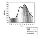
図3は、エネルギー供給プラント3の一次エネルギー消費量とエネルギーコストとの関係の一例を示す図である。
グラフG1は、1次エネルギー消費量のZEB化乗数γに応じた変化を示す。グラフG2は、エネルギーコストのZEB化乗数γに応じた変化を示す。上述のように、ZEB化乗数γは、ZEB化を達成するための制約条件の重みを示す。そのため、図3に示すように、ZEB化乗数γが大きくなるのに従い、ZEB化の達成に関する一次エネルギー消費量は、小さくなる。これに対し、ZEB化乗数γが大きくなるのに従い、エネルギーコストは大きくなる。
Next, the ZEB multiplier γ will be described.
FIG. 3 is a diagram illustrating an example of the relationship between the primary energy consumption of the
Graph G1 shows the change according to the ZEB multiplier γ of the primary energy consumption. The graph G2 shows a change according to the ZEB multiplier γ of the energy cost. As described above, the ZEB multiplier γ indicates the weight of a constraint condition for achieving ZEB conversion. Therefore, as shown in FIG. 3, as the ZEB multiplier γ increases, the primary energy consumption related to the achievement of ZEB decreases. On the other hand, the energy cost increases as the ZEB multiplier γ increases.
例えば、ZEB化乗数γが0のときの年間運転計画緩和問題は、ZEB制約を考慮しないエネルギーコストのみを最小化する問題である。従って、このときの解は、エネルギーコストを最小化するが、1次エネルギー消費量はプラスとなり、ZEBが達成されない。これに対し、ZEB化乗数γを十分大きくしたときの年間運転計画緩和問題は、ZEBの達成条件を満足することを重視した問題である。従って、このときの解は、エネルギーコストを上昇させるものの、1次エネルギー消費量は小さくなり、場合によってはマイナスとなる。従って、1次エネルギー消費量がゼロまたは負になる範囲で最小のZEB化乗数γであるγoptを算出することにより、ZEBを達成しつつ、エネルギーコストを最小化することができる。 For example, the annual operation plan relaxation problem when the ZEB multiplier γ is 0 is a problem of minimizing only the energy cost without considering the ZEB constraint. Thus, the solution at this time minimizes energy costs, but the primary energy consumption is positive and ZEB is not achieved. On the other hand, the annual operation plan relaxation problem when the ZEB multiplier γ is sufficiently large is an issue that places importance on satisfying the ZEB achievement condition. Therefore, although the solution at this time increases the energy cost, the primary energy consumption is reduced and may be negative in some cases. Therefore, by calculating γ opt which is the minimum ZEB multiplier γ within a range where the primary energy consumption becomes zero or negative, the energy cost can be minimized while achieving ZEB.
運転計画作成装置1の構成についての説明に戻る。
図4は、年間運転計画作成部191の構成の一例を示す図である。
年間運転計画作成部191は、ZEB化乗数初期化部1911と、収束判定部1912と、ZEB化乗数更新部1913と、を備える。
Returning to the description of the configuration of the operation
FIG. 4 is a diagram illustrating an example of the configuration of the annual operation
The annual operation
ZEB化乗数初期化部1911は、運転計画の作成に当り、ZEB化乗数γを初期化する。ZEB化乗数初期化部1911は、所定の初期値を演算結果記憶部16のZEB化乗数データ163に記憶させる。ZEB化乗数初期化部1911は、例えば、ZEB化乗数γの初期値を0に設定する。
The
収束判定部1912は、演算結果記憶部16からZEB化乗数データ163が示すZEB化乗数γにおいて、年間需要予測部181から取得した年間需要予測データが示す年間需要予測の条件において、式(23)の解が収束しているか否かを判定する。より具体的には、収束判定部1912は、年間需要予測データの1日毎のデータを日間運転計画作成部192に出力することにより、日間運転計画作成部192に式(24)を365日分解かせ、式(23)の解が収束しているか否かを判定する。式(23)の解が収束していないと判定した場合、収束判定部1912は、解が収束していないことをZEB化乗数更新部1913に通知する。収束していると判定した場合、算出した解に基づいた1年間の運転計画を作成する。収束判定部1912は、作成した1年間の運転計画を演算結果記憶部16に年間計画データ161として記憶させる。
The
ZEB化乗数更新部1913は、収束判定部1912から解が収束していないことを通知されると、演算結果記憶部16に記憶されているZEB化乗数データ163が示すZEB化乗数γを更新し、演算結果記憶部16に記憶させる。ZEB化乗数更新部1913は、例えば、二分法などのアルゴリズムを用いてZEB化乗数γを更新する。
When notified by the
図5は、日間運転計画作成部192の構成の一例を示す図である。
日間運転計画作成部192は、日間需要予測部182から取得した日間需要予測データ、または、年間運転計画作成部191から取得した年間需要データの1日毎のデータに基づいて、1日間の運転計画を作成する。また、日間運転計画作成部192は、制約条件式(3)〜(20)式を参照し、当該式を満たすように運転計画を作成する。日間運転計画作成部192は、ZEB化乗数反映部1921と、算出部1922と、冷熱供給装置運転計画作成部1926と、コジェネ・ボイラ運転計画作成部1927と、蓄熱槽・蓄電池運転計画作成部1928と、を備える。
FIG. 5 is a diagram illustrating an example of the configuration of the daily operation
The daily operation
ZEB化乗数反映部1921は、演算結果記憶部16からZEB化乗数データ163を取得し、取得したZEB化乗数データ163が示すZEB化乗数γを式(24)のZEB化乗数γに反映させる。
The
算出部1922は、ZEB化乗数反映部1921が設定したZEB化乗数γに基づいて、式(3)〜(20)の制約条件の下で目的関数式(24)の最適解を算出する。算出部1922は、消費量算出部1923と、コスト算出部1924と、最適化問題計算部1925と、を備える。
The
消費量算出部1923は、エネルギー供給プラント3によるエネルギーの消費量に係る値を算出する。消費量算出部1923は、例えば、冷熱供給装置運転計画作成部1926、コジェネ・ボイラ運転計画作成部1927、および蓄熱槽・蓄電池運転計画作成部1928が作成したエネルギー供給プラント3の運転計画に基づくエネルギーの消費量を算出する。そして、消費量算出部1923は、当該消費量の一次エネルギー換算量、すなわち一次エネルギー消費量を算出する。
The
コスト算出部1924は、エネルギー供給プラント3が消費するエネルギーのエネルギーコストに係る値を算出する。コスト算出部1924は、例えば、冷熱供給装置運転計画作成部1926、コジェネ・ボイラ運転計画作成部1927、および蓄熱槽・蓄電池運転計画作成部1928が作成したエネルギー供給プラント3の運転計画に基づく、エネルギーコストを算出する。
The
最適化問題計算部1925は、消費量算出部1923およびコスト算出部1924が算出する一次エネルギー消費量およびエネルギーコストに基づいて、例えば、式(24)の左辺の値を算出する。最適化問題計算部1925は、年間需要データの1日毎のデータに基づいて算出した式(24)の左辺の値を、1日分の日間運転計画緩和問題の解として、年間運転計画作成部191に出力する。
The optimization
冷熱供給装置運転計画作成部1926は、日間需要予測部182から取得した日間需要予測データ、または、年間運転計画作成部191から取得した年間需要データの1日毎のデータから1日間の時刻毎の冷熱需要を取得する。冷熱供給装置運転計画作成部1926は、取得した時刻毎の冷熱需要に応じた冷熱を建物2に供給するための冷熱供給装置の運転計画を作成する。冷熱供給装置運転計画作成部1926は、作成した運転計画に基づいて冷熱供給装置を運転したときに必要となる電力および温熱を、算出部1922に算出させる。
The cooling / heating device operation
冷熱供給装置運転計画作成部1926は、日間需要予測部182から取得した日間需要予測データに基づいて作成した運転計画を、演算結果記憶部16に日間計画データ162として記憶させる。また、冷熱供給装置運転計画作成部1926は、年間運転計画作成部191から取得した年間需要データの1日毎のデータに基づいて作成した運転計画を、日にちと対応付けて、演算結果記憶部16に年間計画データ161として記憶させる。
The cold energy supply apparatus operation
コジェネ・ボイラ運転計画作成部1927は、CGS321およびボイラ322の運転計画を作成する。日間需要予測部182から取得した日間需要予測データ、または、年間運転計画作成部191から取得した年間需要データの1日毎のデータから1日間の時刻毎の温熱需要および電力需要を取得する。コジェネ・ボイラ運転計画作成部1927は、取得した時刻毎の電力需要および温熱需要に応じた電力および温熱を建物2に供給するための電力供給装置および温熱供給装置の運転計画を作成する。コジェネ・ボイラ運転計画作成部1927は、作成した運転計画に基づいて温熱供給装置および電力供給装置を運転したときに必要となる受電電力、バイオマス燃料、およびガスの量を、算出部1922に算出させる。
The cogeneration boiler operation
コジェネ・ボイラ運転計画作成部1927は、日間需要予測部182から取得した日間需要予測データに基づいて作成した運転計画を、演算結果記憶部16に日間計画データ162として記憶させる。また、コジェネ・ボイラ運転計画作成部1927は、年間運転計画作成部191から取得した年間需要データの1日毎のデータに基づいて作成した運転計画を日にちと対応付けて、演算結果記憶部16に年間計画データ161として記憶させる。
The cogeneration boiler operation
蓄熱槽・蓄電池運転計画作成部1928は、温熱槽323および冷熱槽333の蓄熱放熱計画と蓄電池313の蓄電放電計画とを作成する。蓄熱槽・蓄電池運転計画作成部1928は、エネルギーコストの時間変化を鑑みて、エネルギーコストが高いときに放熱および放電を行い、エネルギーコストが安いときに蓄熱および蓄電が行われるように、蓄熱計画および蓄電計画を作成する。蓄熱槽・蓄電池運転計画作成部1928は、作成した運転計画に基づいてエネルギー供給プラント3を運転した時のエネルギーコストを、算出部1922に算出させる。
The heat storage tank / battery operation
蓄熱槽・蓄電池運転計画作成部1928は、日間需要予測部182から取得した日間需要予測データに基づいて作成した運転計画を、演算結果記憶部16に日間計画データ162として記憶させる。また、蓄熱槽・蓄電池運転計画作成部1928は、年間運転計画作成部191から取得した年間需要データの1日毎のデータに基づいて作成した運転計画を日にちと対応付けて、演算結果記憶部16に年間計画データ161として記憶させる。
The heat storage tank / battery operation
次に、運転計画作成装置1の動作について説明する。
図6は、年間運転計画作成時における運転計画作成装置1の動作の一例を示すフローチャートである。
まず、運転計画作成装置1は、エネルギー供給プラント3の過去のプロセスデータおよび過去の気象データに基づいて、建物2による年間のエネルギー需要を予測する(ステップS101)。次に、運転計画作成装置1は、予測された年間のエネルギー需要に基づいて、ZEB化乗数γの算出と年間運転計画の作成とを行う(ステップS102)。そして、運転計画作成装置1は、作成した年間運転計画を表示部に表示し(ステップS103)、処理を終了する。
Next, the operation of the operation
FIG. 6 is a flowchart showing an example of the operation of the operation
First, the operation
図7は、図6のステップS102における、運転計画作成装置1の動作の一例を示すフローチャートである。
まず、運転計画作成装置1は、ZEB化乗数γを初期化する(ステップS201)。次に、運転計画作成装置1は、ZEB化乗数γの設定値に基づいて、日間運転計画緩和問題を365日分解き、その総和を解として算出する最適化計算を行う(ステップS202)。次に、運転計画作成装置1は、ステップS202における最適化計算の解が収束しているか否かを判定する(ステップS203)。ここで、運転計画作成装置1は、例えば、年間運転計画緩和問題の解が、一定の反復回数の間、所定の閾値以上に改善されない場合、最適化計算の解が収束していると判定する。
FIG. 7 is a flowchart showing an example of the operation of the operation
First, the operation
最適化計算の解が収束していると判定した場合(ステップS203;YES)、運転計画作成装置1は、処理を終了する。また、最適化計算の解が収束していないと判定した場合(ステップS203;NO)、運転計画作成装置1は、ZEB化乗数γを更新する(ステップS204)。そして、運転計画作成装置1は、ステップS202の処理に戻り、更新されたZEB化乗数γに基づいて、最適化計算を行う。
When it determines with the solution of optimization calculation having converged (step S203; YES), the driving
図8は、図7のステップS202における、運転計画作成装置1の動作の一例を示すフローチャートである。
まず、運転計画作成装置1は、ZEB化乗数γを取得する(ステップS301)次に、運転計画作成装置1は、1日間の時刻毎に、以下のステップS302〜S304の処理を行う。運転計画作成装置1は、図6のステップS101において予測した、時刻毎の冷熱需要を取得する(ステップS302)。次に、運転計画作成装置1は、取得した冷熱需要に応じた冷熱を供給するための冷熱供給装置の運転計画を作成する(ステップS303)。
FIG. 8 is a flowchart showing an example of the operation of the operation
First, the operation
冷熱供給装置の運転計画は、冷熱供給装置各々の起動優先順位に従って決定する。起動優先順位は、例えば、冷熱生成単価表を用いて、冷熱生成単価の安い冷熱供給装置から順に決定する。
図9は、エネルギー供給プラント3が備える冷熱供給装置の冷熱生成単価の一例を示す表である。
The operation plan of the cold energy supply apparatus is determined according to the activation priority of each of the cold energy supply apparatuses. For example, the activation priority order is determined in order from the cold energy supply device having a low cold energy generation unit price using a cold energy generation unit price table.
FIG. 9 is a table showing an example of the cold heat generation unit price of the cold heat supply device included in the
図9に示す冷熱生成単価表は、各冷熱供給装置が定格で運転された場合に、冷熱の単位熱量[kWh]を生成するために必要な燃料あるいは電力の価格を示す表である。図9に示す表において、行L1は時刻を示す。また、行L2は、空冷冷凍機331が1[kWh]の冷熱を生成するために必要とする燃料の単価を示す。また、行L3は、水冷冷凍機332が1[kWh]の冷熱を生成するために必要とする燃料の単価を示す。また、行L4は、吸収式冷凍機334が1[kWh]の冷熱を生成するために必要とする燃料の単価を示す。ここで、本実施形態において、空冷冷凍機331および水冷冷凍機332は電動式であるため、行L2およびL3は、単位冷熱量を生成するために必要な電力価格を示す。また、吸収式冷凍機334は温熱式であるため、行L4は、単位冷熱量を生成するために必要な温熱量を生成するために必要なガス価格を示す。
The cold heat generation unit price table shown in FIG. 9 is a table showing the price of fuel or electric power necessary for generating a unit heat quantity [kWh] of cold heat when each cold heat supply apparatus is operated at a rating. In the table shown in FIG. 9, row L1 indicates time. The row L2 indicates the unit price of fuel that is required for the air-cooled
図9の例において、例えば、0時から7時までと、22時と、23時との時間帯において、1[kWh]の冷熱を生成するために必要とする燃料の単価は、水冷冷凍機332、空冷冷凍機331、吸収式冷凍機334の順に低い。これに対し、8時から21時までの時間帯において、1[kWh]の冷熱を生成するために必要とする燃料の単価は、吸収式冷凍機334、水冷冷凍機332、空冷冷凍機331の順に低い。そのため、0時から7時までと、22時と、23時との時間帯において、水冷冷凍機332の起動優先順位が1、空冷冷凍機331の起動優先順位が2、吸収式冷凍機334の起動優先順位が3であり、8時から21時までの時間帯において、吸収式冷凍機334の起動優先順位が1、水冷冷凍機332の起動優先順位が2、空冷冷凍機331の起動優先順位が3である。
In the example of FIG. 9, for example, in the time zone from 0:00 to 7:00, 22:00, and 23:00, the unit price of fuel required to generate 1 [kWh] cold is the water-cooled
図10は、運転計画作成装置1による運転計画の作成方法の一例を説明するための図である。
図10に示すグラフにおいて、縦軸は冷熱(冷水)のエネルギー量を示し、横軸は時刻を示す。また、折れ線グラフは、冷熱需要の時間変化を示す。また、2つの棒グラフは、それぞれ、水冷冷凍機332による出力冷熱と、吸収式冷凍機334による出力冷熱とを示す。なお、本実施形態において、一例として、空冷冷凍機331の最大出力は300[kWh]、水冷冷凍機332の最大出力は600[kWh]であり、吸収式冷凍機334の最大出力は300[kWh]であるとする。
FIG. 10 is a diagram for explaining an example of an operation plan creation method by the operation
In the graph shown in FIG. 10, the vertical axis indicates the amount of cold energy (cold water), and the horizontal axis indicates time. Moreover, a line graph shows the time change of a cold demand. Moreover, two bar graphs respectively show the output cold heat by the water-cooled
図9を用いて説明した時刻毎の起動優先順位に従うと、運転計画作成装置1は、0時から7時までと、22時と、23時との時間帯において、起動優先順位が1である水冷冷凍機332が、冷熱需要に応じた冷熱を供給するように運転計画を作成する。この時間帯において、冷熱需要は、水冷冷凍機332の最大出力以下であるため、水冷冷凍機332の運転のみで冷熱需要に対応する。また、8時から21時までの時間帯において、運転計画作成装置1は、起動優先順位が1である吸収式冷凍機334がその最大出力の300[kWh]までの冷熱を供給し、300[kWh]を超える場合は、起動優先順位が2である水冷冷凍機332が冷熱需要に対する不足分を供給するように運転計画を作成する。また、運転計画作成装置1は、冷熱供給装置の運転計画の作成において、冷熱槽333の運用を考慮してよい。例えば、水冷冷凍機332のエネルギーコストが高い時間帯において、冷熱槽333が放熱を行い、冷熱負荷を持ち替えるようにする。そして、運転計画作成装置1は、水冷冷凍機332のエネルギーコストが低い時間帯に、持ち替えた冷熱を予め生成し、冷熱槽333に蓄熱するように、運転計画を作成する。
According to the activation priority for each time described with reference to FIG. 9, the operation
図8の説明に戻る。ステップS303の処理を終えると、運転計画作成装置1は、作成した運転計画に基づいて、冷熱供給装置の運転に必要な温熱および電力を算出する(ステップS304)。次に、運転計画作成装置1は、例えば、1日間の時刻毎に、以下のステップS305〜S307の処理を行う。運転計画作成装置1は、図6のステップS101において予測した時刻毎の温熱需要および電力需要とを取得する。また、運転計画作成装置1は、ステップS304において算出した冷熱供給装置の運転に必要な温熱および電力を、予測した温熱需要および電力需要に加算する(ステップS305)。次に、運転計画作成装置1は、取得した温熱需要および電力需要に応じた温熱および電力を建物2に供給するためのCGS321およびボイラ322の運転計画を作成する(ステップS306)。
Returning to the description of FIG. When the process of step S303 is completed, the operation
ここで、運転計画作成装置1は、CGS321およびボイラ322について、冷熱供給装置のときと同様に、起動優先順位を決定し、運転計画を作成する。また、運転計画作成装置1は、単位温熱量を生成するために必要な燃料価格を示す温熱生成単価に基づいて起動優先順位を決定する。また、CGS321の場合は、温熱と電力とを同時に生成・供給するものとして計算する。また、CGS321およびボイラ322の運転計画の作成において、運転計画作成装置1は、気象条件に基づいてPV312による発電量を推定し、推定した発電量を電力需要から差し引いて、運転計画を作成してもよい。
Here, the operation
また、運転計画作成装置1は、温熱槽323について、冷熱槽333の運用と同様に、温熱槽323からの放熱により、CGS321あるいはボイラ322の温熱負荷を持ち替えることによりエネルギーコストを削減できる場合に、持ち替えを実施させるように運転計画を作成する。また、蓄電池313は、受電電力が負になり逆潮流を生じている時間帯に逆潮流分の電力量を充電する。そして、運転計画作成装置1は、受電電力量が正であり、電力単価の最も高い時間帯に、逆潮流を起こさないように蓄電池313を放電させる。
運転計画作成装置1は、ステップS306において作成した運転計画に基づいて、CGS321およびボイラ322の運転に必要な燃料および電力を算出し(ステップS307)、処理を終了する。
In addition, the operation
The operation
図11は、年間運転計画の修正時における運転計画作成装置1の動作の一例を示すフローチャートである。
まず、運転計画作成装置1は、例えば、1ヶ月毎に、必要に応じて建物2の1年間のエネルギー需要の予測修正を行う(ステップS401)。ただし、過去の日にちに対しては、エネルギー需要の予測修正は行わない。また、予測の前提となるデータが変わらない場合には、予測修正を行う必要はない。
FIG. 11 is a flowchart showing an example of the operation of the operation
First, for example, the operation
そして、運転計画作成装置1は、エネルギー供給プラント3の運転実績と修正した年間需要予測とに基づいて、ZEB化乗数γを再計算し、年間運転計画を修正し(ステップS402)、処理を終了する。ここで、ZEB化乗数γの再計算および年間運転計画の作成において、過去の日にちに対しては、エネルギー供給プラント3の1次エネルギー消費量の実績値を用いる。
Then, the operation
図12は、実際のエネルギー供給プラント3の運用時における日間運手計画の作成時における運転計画作成装置1の動作の一例を示すフローチャートである。
まず、運転計画作成装置1は、例えば、毎日の所定の時間に、プロセスデータと、過去の気象データおよび未来の気象予測データに基づいて、1日間のエネルギー需要の予測を行う(ステップS501)。そして、運転計画作成装置1は、作成した日間需要予測データに基づき、エネルギー供給プラント3が備えるエネルギー供給装置の1日間の運転計画を作成する(ステップS502)。このとき、ZEB化乗数γには、例えば、図6のステップS102において算出した値、または、図11のステップS402において再計算した値を用いる。運転計画作成装置1は、作成した1日間の運転計画を制御装置5に送信し、処理を終了する(ステップS503)。
FIG. 12 is a flowchart illustrating an example of the operation of the operation
First, the operation
以上のように、運転計画作成装置1は、消費量算出部1923と、コスト算出部1924と、運転計画作成部19と、を備える。消費量算出部1923は、建物2に対してエネルギーを供給するエネルギー供給プラント3による一次エネルギー消費量を算出する。コスト算出部1924は、エネルギー供給プラント3がエネルギーの生成に要するエネルギーコストを算出する。運転計画作成部19は、消費量算出部1923が算出する一次エネルギー消費量とコスト算出部1924が算出するエネルギーコストとに基づいて、一次エネルギー消費量またはエネルギーコストに関する所定の目標を達成するように、複数のエネルギー供給装置の運転計画を作成する。
As described above, the operation
これにより、運転計画作成装置1は、例えば、エネルギー供給プラント3の運転計画の作成時において、一次エネルギー消費量とエネルギーコストとを鑑みて運転計画を作成するため、エネルギー供給プラント3が備えるエネルギー供給装置の一次エネルギー消費量を小さくしつつ、エネルギーコストを小さくすることができる。従って、運転計画作成装置1は、例えば、建物2のZEB化を達成しつつ、低いエネルギーコストでエネルギー供給プラント3を運転することができる。
Thereby, for example, when the operation
また、運転計画作成部19は、消費量算出部1923が算出する一次エネルギー消費量を示す値にZEB化乗数γを乗算し、当該乗算した値をコスト算出部1924が算出するエネルギーコストを示す値に加算した値に基づいて、エネルギー供給プラント3の運転計画を作成する。これにより、運転計画作成装置1は、年間運転計画問題を少ない計算量で解くことができる。従って、運転計画作成装置1は、エネルギー供給プラント3が備えるエネルギー供給装置の一次エネルギー消費量を小さくしつつ、エネルギーコストを小さくするための運転計画を短時間で作成することができる。
Further, the operation
また、運転計画作成装置1は、所定の目標として、消費量算出部1923が算出する一次エネルギー消費量がゼロまたは負の値とする。これにより、運転計画作成装置1は、例えば、さらに確実に建物2のZEB化を達成することができる。
Further, the operation
また、消費量算出部1923は、所定の期間における一次エネルギー消費量を算出し、コスト算出部1924は、所定の期間におけるエネルギーコストを算出する。これにより、運転計画作成装置1は、例えば1年間などの所定の期間における一次エネルギー消費量とエネルギーコストとに基づいて運転計画を作成する。従って、例えば、所定の期間において、一次エネルギーをゼロまたは負の値にするなどの目標を、さらに確実に達成することができる。
Further, the
また、消費量算出部1923は、所定の期間における第1の一次エネルギー消費量と、上述した所定の期間に比して短い期間における第2の一次エネルギー消費量とを算出し、コスト算出部1924は、上述した所定の期間における第1のエネルギーコストと、上述した所定の期間に比して短い期間における第2のエネルギーコストとを算出し、運転計画作成部19は、第1の一次エネルギー消費量と第1のエネルギーコストとに基づいて作成した運転計画を、第2の一次エネルギー消費量と第2のエネルギーコストとに基づいて修正する。
Further, the
これにより、運転計画作成装置1は、例えば、1年間の一次エネルギー消費量とエネルギーコストとに基づいて作成した運転計画を、1年間よりも短い1ヶ月間または1日間の一次エネルギー消費量とエネルギーコストとに基づいて修正する。従って、運転計画作成装置1は、例えば、1年間における長期的な目標に対して作成した運転計画と、エネルギー供給プラント3の実際の運転状態とのずれを、1日単位で修正することができるため、建物2のZEB化の達成などの長期的な目標を、さらに確実に達成することができる。
As a result, the operation
(第2の実施形態)
図13は、第2の実施形態の運転計画作成装置の全体構成の一例を示す図である。
第2の実施形態に係る運転計画作成装置1aは、ビルや住宅などの建物に電力、冷熱、温熱などのエネルギーを供給するエネルギー供給プラントの仮想モデルに対して運転計画を作成することにより、建物のZEB化の達成時におけるエネルギーコストをシミュレーションするシミュレーターである。運転計画作成装置1aは、例えば、サーバ装置、パーソナルコンピュータ、タブレット端末装置、スマートフォンなどである。
(Second Embodiment)
FIG. 13 is a diagram illustrating an example of the overall configuration of the operation plan creation apparatus according to the second embodiment.
The operation
また、運転計画作成装置1aは、例えば、装置の内部にCPUや記憶装置を備える。運転計画作成装置1aが備える記憶装置は、例えば、HDD、フラッシュメモリ、EEPROM、ROM、またはRAMなどを備え、ファームウェアやアプリケーションプログラムなど、CPUが実行するための各種プログラムやCPUが実行した処理の結果などを記憶する。以下、本実施形態の説明では、第1の実施形態と同一の機能を有する構成については、同一の符号を使用し、説明を省略する。
The operation
運転計画作成装置1aは、ネットワーク9に接続され、ネットワーク9を介して、気象情報サーバ8と通信を行う。ネットワーク9は、例えば、携帯電話網、PHS網、VPN網、専用通信回線網、WAN、LAN、PSTNなどによって構成される情報通信ネットワークであり、また、これらの組み合わせであってもよい。
The operation
運転計画作成装置1aは、通信部10と、モデル入力部11と、表示部12と、プロセスデータ記憶部13aと、気象データ記憶部14と、プラントモデル記憶部15と、演算結果記憶部16aと、演算処理部17aと、気象データ取得部102と、モデル入力制御部111と、表示制御部121と、プロセスデータ入力部132と、プロセスデータ入力制御部133と、を備える。
The operation
プロセスデータ記憶部13aは、プロセスデータ131aを記憶する。プロセスデータ131aは、例えば、プラントモデル記憶部15aが記憶するプラントモデルデータ151aおよびモデルパラメータデータ152aが示すシミュレーション対象のエネルギー供給プラントに構成が類似したエネルギー供給プラントの運用記録の情報を含む。また、プロセスデータ131aは、シミュレーション対象の建物のエネルギー需要の記録の情報などを含む。これらの情報は日時と対応付けられて記憶され、その時間間隔は、例えば、1時間単位である。
The process
プラントモデル記憶部15aは、プラントモデルデータ151aと、モデルパラメータデータ152aと、を記憶する。
プラントモデルデータ151aは、シミュレーション対象のエネルギー供給プラントの態様を示すデータである。プラントモデルデータ151aは、例えば、シミュレーション対象のエネルギー供給プラントが備えるエネルギー供給装置の種類とその接続態様とを示す。また、プラントモデルデータ151aは、受電設備が受電する電力、エネルギー供給プラントが消費するバイオマス燃料、およびガスのエネルギー単価の日時毎のデータを含む。また、プラントモデルデータ151aは、電力、ガス、バイオマス燃料の一次エネルギー換算係数のデータを含む。
The plant
The
モデルパラメータデータ152aは、シミュレーション対象のエネルギー供給プラントが備えるエネルギー供給装置の詳細を示すデータである。モデルパラメータデータ152aは、例えば、各エネルギー供給装置が供給するエネルギーの最大出力や、各エネルギー供給装置の入力エネルギーに対する出力エネルギーの変換効率などのデータを含む。また、モデルパラメータデータ152aは、気象条件によってエネルギー生成効率の変化するPVなどについて、気象条件に応じたエネルギーの出力などのデータを含む。また、モデルパラメータデータ152aは、蓄電池、温熱槽、および冷熱槽が蓄積可能なエネルギー量のデータを含む。
The
演算結果記憶部16aは、年間計画データ161と、ZEB化乗数データ163と、を備える。
プロセスデータ入力部132は、プロセスデータの入力を受け付ける。プロセスデータ入力部132は、例えば、タッチパネルやマウス、キーボードなどの入力装置を備える。また、プロセスデータ入力部132は、プロセスデータを記憶する外部記憶装置と接続し、当該プロセスデータを取得するための通信用インターフェースを備えてもよい。
The calculation
The process
プロセスデータ入力制御部133、気象データ取得部102、運転計画送信制御部103、モデル入力制御部111、表示制御部121、および演算処理部17aは、例えば、運転計画作成装置1aが記憶装置に記憶するプログラムを、CPUが実行することによって機能する。
The process data
プロセスデータ入力制御部133は、プロセスデータ入力部132が取得したプロセスデータをプロセスデータ記憶部13aに記憶させる。
演算処理部17aは、年間需要予測部181aと、運転計画作成部19aと、を備える。年間需要予測部181aは、第1の実施形態の運転計画作成装置1が備える年間需要予測部181と同様の処理を行う。ただし、プロセスデータ131の代わりにプロセスデータ131aに基づいて、シミュレーション対象の建物が必要とするエネルギーの年間需要予測を行う。
The process data
The
運転計画作成部19aは、第1の実施形態の運転計画作成部19と同様の処理を行う。ただし、プラントモデルデータ151の代わりにプラントモデルデータ151aに基づき、また、モデルパラメータデータ152の代わりにモデルパラメータデータ152aに基づき、シミュレーション対象のエネルギー供給プラントの運転計画を作成する。
The operation
以上のように、運転計画作成装置1aは、消費量算出部1923と、コスト算出部1924と、運転計画作成部19と、を備える。消費量算出部1923は、建物2に対してエネルギーを供給する複数のエネルギー供給装置による一次エネルギー消費量を算出する。コスト算出部1924は、複数のエネルギー供給装置がエネルギーの生成に要するエネルギーコストを算出する。運転計画作成部19は、消費量算出部1923が算出する一次エネルギー消費量とコスト算出部1924が算出するエネルギーコストとに基づいて、一次エネルギー消費量またはエネルギーコストに関する所定の目標を達成するように、複数のエネルギー供給装置の運転計画を作成する。
As described above, the operation
これにより、運転計画作成装置1aは、例えば、エネルギー供給プラントと建物とについてシミュレーションを行い、建物がZEB化を達成できるか否かを判定したり、ZEBを達成する場合に要するエネルギーコストを算出したりすることができる。従って、例えば、エネルギー供給プラントとエネルギー供給先の建物の着工前に、ZEB化の実現可能性を判断することができる。
Thereby, the operation
なお、図1に示した構成は一例であり、例えば、いずれのエネルギー供給装置を採用するか、或いは採用しないかについて、特に制限はない。また、エネルギー供給装置の接続態様も図1に示したものに限らない。また、エネルギー供給プラントは、例示されていないエネルギー供給装置を備えてもよい。 The configuration illustrated in FIG. 1 is an example, and for example, there is no particular limitation on which energy supply device is used or not. Further, the connection mode of the energy supply apparatus is not limited to that shown in FIG. The energy supply plant may include an energy supply device that is not illustrated.
なお、上述の実施形態では、プロセスデータや気象データが1時間単位で記録されていることとしたが、例えば30分単位や15分単位、2時間単位などで記録されていてもよい。また、同様に、運転計画作成装置は、1時間ではなく、例えば30分単位や15分単位、2時間単位などで、運転計画を作成してよく、これらの時間間隔に特に制限はない。 In the above-described embodiment, process data and weather data are recorded in units of one hour, but may be recorded in units of 30 minutes, units of 15 minutes, units of 2 hours, or the like. Similarly, the operation plan creation device may create an operation plan not in one hour but in units of 30 minutes, 15 minutes, 2 hours, etc., and these time intervals are not particularly limited.
なお、年間運転計画緩和問題および日間運転計画緩和問題についての各式の情報は、例えば、プラントモデル記憶部15、15aのプラントモデルデータ151、151aやモデルパラメータデータ152、152aとして記憶されてよい。
In addition, the information of each type | formula about an annual operation plan relaxation problem and a daily operation plan relaxation problem may be memorize | stored as the
以上説明した少なくともひとつの実施形態によれば、一次エネルギーとエネルギーコストとに基づいて運転計画を作成するという技術的特徴を持つことにより、建物の正味の1次エネルギー消費量をゼロまたは負にし、いわゆるZEB化を達成する中で、エネルギーコストを最小化して、エネルギー供給プラントを運転することができる。 According to at least one embodiment described above, by having the technical feature of creating an operation plan based on primary energy and energy cost, the net primary energy consumption of the building is made zero or negative, In achieving so-called ZEB conversion, the energy supply plant can be operated with the energy cost minimized.
本発明のいくつかの実施形態を説明したが、これらの実施形態は、例として提示したものであり、発明の範囲を限定することは意図していない。これら実施形態は、その他の様々な形態で実施されることが可能であり、発明の要旨を逸脱しない範囲で、種々の省略、置き換え、変更を行うことができる。これら実施形態やその変形は、発明の範囲や要旨に含まれると同様に、特許請求の範囲に記載された発明とその均等の範囲に含まれるものである。 Although several embodiments of the present invention have been described, these embodiments are presented by way of example and are not intended to limit the scope of the invention. These embodiments can be implemented in various other forms, and various omissions, replacements, and changes can be made without departing from the spirit of the invention. These embodiments and their modifications are included in the scope and gist of the invention, and are also included in the invention described in the claims and the equivalents thereof.
なお、上述した各実施形態における運転計画作成装置1、1aおよび制御装置5の一部、例えば、プロセスデータ取得部101、気象データ取得部102、運転計画送信制御部103、モデル入力制御部111、表示制御部121、演算処理部17、需要予測部18、年間需要予測部181、日間需要予測部182、運転計画作成部19、年間運転計画作成部191、日間運転計画作成部192、ZEB化乗数初期化部1911、収束判定部1912、ZEB化乗数更新部1913、ZEB化乗数反映部1921、算出部1922、消費量算出部1923、コスト算出部1924、最適化問題計算部1925、冷熱供給装置運転計画作成部1926、コジェネ・ボイラ運転計画作成部1927、および蓄熱槽・蓄電池運転計画作成部1928などをコンピュータで実現するようにしてもよい。その場合、この機能を実現するためのプログラムをコンピュータ読み取り可能な記録媒体に記録して、この記録媒体に記録されたプログラムをコンピュータシステムに読み込ませ、実行することによって実現してもよい。なお、ここでいう「コンピュータシステム」とは、運転計画作成装置1、1aおよび制御装置5に内蔵されたコンピュータシステムであって、OS(Operating System)や周辺機器等のハードウェアを含むものとする。
In addition, a part of the operation
また、「コンピュータ読み取り可能な記録媒体」とは、フレキシブルディスク、光磁気ディスク、ROM、CD−ROM等の可搬媒体、コンピュータシステムに内蔵されるハードディスク等の記憶装置のことをいう。さらに「コンピュータ読み取り可能な記録媒体」とは、インターネット等のネットワークや電話回線等の通信回線を介してプログラムを送信する場合の通信線のように、短時間、動的にプログラムを保持するもの、その場合のサーバやクライアントとなるコンピュータシステム内部の揮発性メモリのように、一定時間プログラムを保持しているものも含んでもよい。また上記プログラムは、前述した機能の一部を実現するためのものであってもよく、さらに前述した機能をコンピュータシステムにすでに記録されているプログラムとの組み合わせで実現できるものであってもよい。 The “computer-readable recording medium” refers to a storage device such as a flexible medium, a magneto-optical disk, a portable medium such as a ROM and a CD-ROM, and a hard disk incorporated in a computer system. Furthermore, the “computer-readable recording medium” is a medium that dynamically holds a program for a short time, such as a communication line when transmitting a program via a network such as the Internet or a communication line such as a telephone line, In this case, a volatile memory inside a computer system that serves as a server or a client may be included that holds a program for a certain period of time. The program may be a program for realizing a part of the functions described above, and may be a program capable of realizing the functions described above in combination with a program already recorded in a computer system.
また、上述した実施形態における運転計画作成装置1、1aおよび制御装置5の一部、または全部を、LSI(Large Scale Integration)等の集積回路として実現してもよい。運転計画作成装置1、1aおよび制御装置5の各機能部は個別にプロセッサ化してもよいし、一部、または全部を集積してプロセッサ化してもよい。また、集積回路化の手法はLSIに限らず専用回路、または汎用プロセッサで実現してもよい。また、半導体技術の進歩によりLSIに代替する集積回路化の技術が出現した場合、当該技術による集積回路を用いてもよい。
Moreover, you may implement | achieve part or all of the operation
1…運転計画作成装置、2…建物、3…エネルギー供給プラント、4…内部ネットワーク4…制御装置、6…外部通信サーバ、7…外部ネットワーク、8…気象情報サーバ、10…通信部、11…モデル入力部、12…表示部、13…プロセスデータ記憶部、14…気象データ記憶部、15…プラントモデル記憶部、16…演算結果記憶部、17…演算処理部、18…需要予測部、19…運転計画作成部、101…プロセスデータ取得部、102…気象データ取得部、103…運転計画送信制御部、111…モデル入力制御部、121…表示制御部、181…年間需要予測部、182…日間需要予測部、191…年間運転計画作成部、192…日間運転計画作成部、1911…ZEB化乗数初期化部、1912…収束判定部、1913…ZEB化乗数更新部、1921…ZEB化乗数反映部、1922…算出部、1923…消費量算出部、1924…コスト算出部、1925…最適化問題計算部、1926…冷凍供給装置運転計画作成部、1927…コジェネ・ボイラ運転計画作成部、1928…蓄熱槽・蓄電池運転計画作成部
DESCRIPTION OF
Claims (7)
前記複数のエネルギー供給装置がエネルギーの生成に要するエネルギーコストを算出するコスト算出部と、
前記消費量算出部が算出する前記一次エネルギー消費量と前記コスト算出部が算出する前記エネルギーコストとに基づいて、前記一次エネルギー消費量がゼロまたは負の値となることである前記一次エネルギー消費量に対する目標を達成した上で、前記エネルギーコストを最小化する前記エネルギーコストに対する目標を夫々達成するように、前記複数のエネルギー供給装置の運転計画を作成する運転計画作成部と、
を備える運転計画作成装置。 A consumption calculator that calculates primary energy consumption by a plurality of energy supply devices that supply energy to the load; and
A cost calculator that calculates an energy cost required for generating energy by the plurality of energy supply devices;
The primary energy consumption is that the primary energy consumption is zero or a negative value based on the primary energy consumption calculated by the consumption calculation unit and the energy cost calculated by the cost calculation unit. An operation plan creation unit that creates an operation plan for the plurality of energy supply devices so as to achieve each of the targets for the energy cost that minimizes the energy cost .
An operation plan creation device comprising:
請求項1に記載の運転計画作成装置。 The operation plan creation unit multiplies the value indicating the primary energy consumption calculated by the consumption calculation unit by a coefficient, and adds the multiplied value to the value indicating the energy cost calculated by the cost calculation unit. The operation plan creation device according to claim 1, wherein an operation plan for the plurality of energy supply devices is created based on the value.
前記コスト算出部は、前記所定の期間における前記エネルギーコストを算出する
請求項1又は2に記載の運転計画作成装置。 The consumption calculation unit calculates the primary energy consumption in a predetermined period,
The cost calculation unit, the operation planning device according to claim 1 or 2 for calculating the energy cost in the predetermined time period.
前記コスト算出部は、前記所定の期間における第1のエネルギーコストと、前記所定の期間に比して短い期間における第2のエネルギーコストとを算出し、
前記運転計画作成部は、前記第1の一次エネルギー消費量と前記第1のエネルギーコストとに基づいて作成した運転計画を、前記第2の一次エネルギー消費量と前記第2のエネルギーコストとに基づいて修正する
請求項3に記載の運転計画作成装置。 The consumption calculation unit calculates a first primary energy consumption in the predetermined period and a second primary energy consumption in a period shorter than the predetermined period,
The cost calculation unit calculates a first energy cost in the predetermined period and a second energy cost in a period shorter than the predetermined period,
The operation plan creation unit creates an operation plan created based on the first primary energy consumption amount and the first energy cost based on the second primary energy consumption amount and the second energy cost. The operation plan creation device according to claim 3 .
運転計画作成装置が、前記複数のエネルギー供給装置がエネルギーの生成に要するエネルギーコストを算出するエネルギーコスト算出過程と、
運転計画作成装置が、前記消費量算出過程において算出した前記一次エネルギー消費量と前記エネルギーコスト算出過程において算出した前記エネルギーコストとに基づいて、前記一次エネルギー消費量がゼロまたは負の値となることである前記一次エネルギー消費量に対する目標を達成した上で、前記エネルギーコストを最小化する前記エネルギーコストに対する目標を夫々達成するように、前記複数のエネルギー供給装置の運転計画を作成する運転計画作成過程と、
を有する運転計画作成方法。 A consumption calculation process in which an operation plan creation device calculates primary energy consumption by a plurality of energy supply devices that supply energy to a load;
An energy cost calculation process in which the operation plan creation device calculates an energy cost required for generating energy by the plurality of energy supply devices;
The primary energy consumption is zero or a negative value based on the primary energy consumption calculated in the consumption calculation process and the energy cost calculated in the energy cost calculation process by the operation plan creation device. An operation plan creation process for creating an operation plan for the plurality of energy supply devices so as to achieve the target for the energy cost that minimizes the energy cost after achieving the target for the primary energy consumption of When,
An operation plan creation method comprising:
負荷に対してエネルギーを供給する複数のエネルギー供給装置による一次エネルギー消費量を算出する消費量算出手順、
前記複数のエネルギー供給装置がエネルギーの生成に要するエネルギーコストを算出するエネルギーコスト算出手順、
前記消費量算出手順において算出された前記一次エネルギー消費量と前記エネルギーコスト算出手順において算出された前記エネルギーコストとに基づいて、前記一次エネルギー消費量がゼロまたは負の値となることである前記一次エネルギー消費量に対する目標を達成した上で、前記エネルギーコストを最小化する前記エネルギーコストに対する目標を夫々達成するように、前記複数のエネルギー供給装置の運転計画を作成する運転計画作成手順、
を実行させるためのプログラム。 On the computer,
A consumption calculation procedure for calculating primary energy consumption by a plurality of energy supply devices that supply energy to a load,
An energy cost calculation procedure for calculating an energy cost required for generating energy by the plurality of energy supply devices;
The primary energy consumption is zero or a negative value based on the primary energy consumption calculated in the consumption calculation procedure and the energy cost calculated in the energy cost calculation procedure. An operation plan creation procedure for creating an operation plan for the plurality of energy supply devices so as to achieve each of the targets for the energy cost that minimizes the energy cost after achieving the target for energy consumption .
A program for running
Priority Applications (5)
| Application Number | Priority Date | Filing Date | Title |
|---|---|---|---|
| JP2014006158A JP6334177B2 (en) | 2014-01-16 | 2014-01-16 | Operation plan creation device, control device, operation plan creation method, and program |
| US15/111,335 US20160349780A1 (en) | 2014-01-16 | 2014-12-11 | Operation plan generation device, control device, operation plan generation method, and program |
| PCT/JP2014/082809 WO2015107809A1 (en) | 2014-01-16 | 2014-12-11 | Operating plan creation device, control device, operating plan creation method, and program |
| EP14878489.5A EP3096285A4 (en) | 2014-01-16 | 2014-12-11 | Operating plan creation device, control device, operating plan creation method, and program |
| SG11201605765YA SG11201605765YA (en) | 2014-01-16 | 2014-12-11 | Operation plan generation device, control device, operation plan generation method, and program |
Applications Claiming Priority (1)
| Application Number | Priority Date | Filing Date | Title |
|---|---|---|---|
| JP2014006158A JP6334177B2 (en) | 2014-01-16 | 2014-01-16 | Operation plan creation device, control device, operation plan creation method, and program |
Related Child Applications (1)
| Application Number | Title | Priority Date | Filing Date |
|---|---|---|---|
| JP2018084585A Division JP6542426B2 (en) | 2018-04-25 | 2018-04-25 | Operation plan creation device, operation plan creation method, and program |
Publications (2)
| Publication Number | Publication Date |
|---|---|
| JP2015135571A JP2015135571A (en) | 2015-07-27 |
| JP6334177B2 true JP6334177B2 (en) | 2018-05-30 |
Family
ID=53542712
Family Applications (1)
| Application Number | Title | Priority Date | Filing Date |
|---|---|---|---|
| JP2014006158A Active JP6334177B2 (en) | 2014-01-16 | 2014-01-16 | Operation plan creation device, control device, operation plan creation method, and program |
Country Status (5)
| Country | Link |
|---|---|
| US (1) | US20160349780A1 (en) |
| EP (1) | EP3096285A4 (en) |
| JP (1) | JP6334177B2 (en) |
| SG (1) | SG11201605765YA (en) |
| WO (1) | WO2015107809A1 (en) |
Families Citing this family (10)
| Publication number | Priority date | Publication date | Assignee | Title |
|---|---|---|---|---|
| JP6720562B2 (en) * | 2016-02-10 | 2020-07-08 | 富士電機株式会社 | Control device, control system, control program, and control method |
| JP2018025962A (en) * | 2016-08-10 | 2018-02-15 | 東京瓦斯株式会社 | Operation plan planning method, operation plan planning device, and program |
| JP6812169B2 (en) * | 2016-08-29 | 2021-01-13 | 川崎重工業株式会社 | Planning equipment and planning method for operation of energy demand equipment |
| JP6735219B2 (en) * | 2016-12-05 | 2020-08-05 | 株式会社日立製作所 | Prediction system and prediction method |
| JP6810597B2 (en) * | 2016-12-19 | 2021-01-06 | アズビル株式会社 | Heat source operation plan calculation device and method |
| JP7075194B2 (en) * | 2017-09-29 | 2022-05-25 | 川崎重工業株式会社 | Waste treatment plan calculation method and waste treatment plan calculation device |
| JP7053299B2 (en) * | 2018-02-15 | 2022-04-12 | 株式会社日立製作所 | Operation plan generation device and operation plan generation method |
| JP7189748B2 (en) * | 2018-11-30 | 2022-12-14 | 東京瓦斯株式会社 | OPERATION CONTROL DEVICE, OPERATION CONTROL METHOD, AND OPERATION CONTROL PROGRAM FOR HEAT SUPPLY FACILITY |
| CN111027750B (en) * | 2019-11-18 | 2022-06-03 | 新奥数能科技有限公司 | Method and device for predicting maintenance time of evaporator |
| JP2022169825A (en) * | 2021-04-28 | 2022-11-10 | 横河電機株式会社 | Evaluation apparatus, evaluation method, evaluation program, control apparatus, and control program |
Family Cites Families (9)
| Publication number | Priority date | Publication date | Assignee | Title |
|---|---|---|---|---|
| JPH0926804A (en) * | 1995-07-11 | 1997-01-28 | Daidan Kk | Heat source operation management device |
| JP2005086953A (en) * | 2003-09-10 | 2005-03-31 | Nippon Telegr & Teleph Corp <Ntt> | Energy supply and demand control method and device |
| US8310094B2 (en) * | 2006-01-27 | 2012-11-13 | Sharp Kabushiki Kaisha | Power supply system |
| JP5179423B2 (en) * | 2009-03-30 | 2013-04-10 | 東京瓦斯株式会社 | Energy system optimization method, energy system optimization apparatus and program |
| JP2011002929A (en) * | 2009-06-17 | 2011-01-06 | Nippon Telegr & Teleph Corp <Ntt> | Distributed power supply system and method of controlling the same |
| CN102414951A (en) * | 2010-02-25 | 2012-04-11 | 松下电器产业株式会社 | Demand and supply control apparatus, demand and supply control method, and program |
| JP5106708B1 (en) * | 2011-12-06 | 2012-12-26 | 中国電力株式会社 | Electricity demand plan adjustment apparatus, method and program |
| JP5908302B2 (en) * | 2012-02-27 | 2016-04-26 | 株式会社東芝 | Storage energy storage optimization device, optimization method and optimization program |
| US9607343B2 (en) * | 2013-08-30 | 2017-03-28 | Hewlett Packard Enterprise Development Lp | Generating a demand response for an energy-consuming facility |
-
2014
- 2014-01-16 JP JP2014006158A patent/JP6334177B2/en active Active
- 2014-12-11 WO PCT/JP2014/082809 patent/WO2015107809A1/en active Application Filing
- 2014-12-11 SG SG11201605765YA patent/SG11201605765YA/en unknown
- 2014-12-11 US US15/111,335 patent/US20160349780A1/en not_active Abandoned
- 2014-12-11 EP EP14878489.5A patent/EP3096285A4/en not_active Withdrawn
Also Published As
| Publication number | Publication date |
|---|---|
| JP2015135571A (en) | 2015-07-27 |
| WO2015107809A1 (en) | 2015-07-23 |
| US20160349780A1 (en) | 2016-12-01 |
| EP3096285A1 (en) | 2016-11-23 |
| EP3096285A4 (en) | 2017-07-12 |
| SG11201605765YA (en) | 2016-09-29 |
Similar Documents
| Publication | Publication Date | Title |
|---|---|---|
| JP6334177B2 (en) | Operation plan creation device, control device, operation plan creation method, and program | |
| CN110417006B (en) | Multi-time scale energy scheduling method for comprehensive energy system | |
| Khatib et al. | A review on sizing methodologies of photovoltaic array and storage battery in a standalone photovoltaic system | |
| Zahboune et al. | Optimal hybrid renewable energy design in autonomous system using Modified Electric System Cascade Analysis and Homer software | |
| Bhayo et al. | Assessment of standalone solar PV-Battery system for electricity generation and utilization of excess power for water pumping | |
| JP5789792B2 (en) | Supply and demand control device, supply and demand control method, and supply and demand control system | |
| Khatib et al. | A review of photovoltaic systems size optimization techniques | |
| JP6385984B2 (en) | Energy management apparatus, energy management method, and energy management program | |
| Menapace et al. | The design of 100% renewable smart urb an energy systems: the case of Bozen-Bolzano | |
| JP2012034444A (en) | Power supply-demand planning device and method thereof | |
| Karami et al. | Optimal scheduling of residential energy system including combined heat and power system and storage device | |
| JP6471011B2 (en) | Storage battery operation plan creation device, storage battery operation plan creation method, and computer program | |
| Afzal et al. | Optimal hybrid renewable energy systems for energy security: a comparative study | |
| Liu et al. | Optimal operation of photovoltaic/diesel generator/pumped water reservoir power system using modified manta ray optimization | |
| Yazdanpanah‐Jahromi et al. | An efficient sizing method with suitable energy management strategy for hybrid renewable energy systems | |
| Schüwer et al. | The potential of grid-orientated distributed cogeneration on the minutes reserve market and how changing the operating mode impacts on CO2 emissions | |
| WO2016006549A1 (en) | Information processing device, information processing method, and storage medium | |
| Li et al. | Two-time-scale coordinated optimal control of building energy systems for demand response considering forecast uncertainties | |
| Papaefthimiou et al. | Grid parity of solar energy: imminent fact or future’s fiction? | |
| Voisin et al. | Climate impact analysis on the optimal sizing of a stand-alone hybrid building | |
| JP6567302B2 (en) | Energy management apparatus, energy management method and program | |
| JP6542426B2 (en) | Operation plan creation device, operation plan creation method, and program | |
| Cai et al. | Economic model-based control of sustainable buildings with photovoltaic (PV) and battery systems considering battery degradation costs | |
| Ran et al. | Coordinated optimization design of buildings and regional integrated energy systems based on load prediction in future climate conditions | |
| Sahoo et al. | Impact of electric vehicles on optimal power dispatch of a micro-grid in competitive electric market |
Legal Events
| Date | Code | Title | Description |
|---|---|---|---|
| A621 | Written request for application examination |
Free format text: JAPANESE INTERMEDIATE CODE: A621 Effective date: 20160307 |
|
| A131 | Notification of reasons for refusal |
Free format text: JAPANESE INTERMEDIATE CODE: A131 Effective date: 20170509 |
|
| A521 | Written amendment |
Free format text: JAPANESE INTERMEDIATE CODE: A523 Effective date: 20170710 |
|
| A711 | Notification of change in applicant |
Free format text: JAPANESE INTERMEDIATE CODE: A712 Effective date: 20170911 Free format text: JAPANESE INTERMEDIATE CODE: A711 Effective date: 20170911 |
|
| A131 | Notification of reasons for refusal |
Free format text: JAPANESE INTERMEDIATE CODE: A131 Effective date: 20171031 |
|
| A521 | Written amendment |
Free format text: JAPANESE INTERMEDIATE CODE: A523 Effective date: 20180104 |
|
| TRDD | Decision of grant or rejection written | ||
| A01 | Written decision to grant a patent or to grant a registration (utility model) |
Free format text: JAPANESE INTERMEDIATE CODE: A01 Effective date: 20180327 |
|
| A61 | First payment of annual fees (during grant procedure) |
Free format text: JAPANESE INTERMEDIATE CODE: A61 Effective date: 20180426 |
|
| R150 | Certificate of patent or registration of utility model |
Ref document number: 6334177 Country of ref document: JP Free format text: JAPANESE INTERMEDIATE CODE: R150 |